ANSI / TIA -568-C - Hubbell Premise Wiring
ANSI / TIA -568-C - Hubbell Premise Wiring
ANSI / TIA -568-C - Hubbell Premise Wiring

Create successful ePaper yourself
Turn your PDF publications into a flip-book with our unique Google optimized e-Paper software.
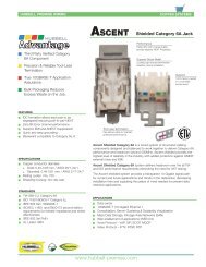
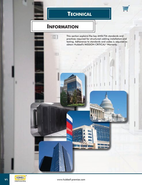
technIcal<br />
InformatIon<br />
This section explains the key <strong>ANSI</strong>/<strong>TIA</strong> standards and<br />
practices required for structured cabling installation and<br />
testing. Adherence to standards and codes is required to<br />
obtain <strong>Hubbell</strong>'s MISSION CRITICAL ® Warranty.<br />
V1<br />
www.hubbell-premise.com
technIcal InformatIon<br />
Subject<br />
Page<br />
Web based Technical ResouRces .......................... V3<br />
inTRoducTion: sTRucTuRed cabling sTandaRds eVoluTion ......... V5<br />
T echnical i nformaT ion<br />
ansi/Tia-<strong>568</strong>-c . .................................... V6<br />
ansi/Tia-<strong>568</strong>-c: hoRizonTal cabling . ..................... V7<br />
FibeR disTances chaRT . ................................. V8<br />
ansi/Tia-<strong>568</strong>-c.1: backbone cabling . .................... V9<br />
ansi/Tia-<strong>568</strong>-c.1: backbone and hoRizonTal cabling sTRucTuRe ....V10<br />
ansi/Tia-<strong>568</strong>-c.1: WoRk aRea . .......................... V11<br />
ansi/Tia-<strong>568</strong>-c.1 . ................................... V12<br />
ansi/Tia-<strong>568</strong>-c.2: balanced TWisTed PaiR cabling comPonenTs .....V13<br />
ansi/Tia-<strong>568</strong>-c.2: balanced TWisTed PaiR PeRmanenT link and<br />
channel Field TesTing ....................................V14<br />
ansi/Tia-<strong>568</strong>-c.0 & c.3: oPTical FibeR cabling and comPonenTs ...V15<br />
Recommended balanced TWisTed PaiR insTallaTion PRacTices . ...... V17<br />
ansi/Tia-569-c: TelecommunicaTions PaThWays and sPaces . ..... V18<br />
ansi/Tia-570-b: ResidenTial TelecommunicaTions<br />
cabling sTandaRd . .................................... V19<br />
ansi/Tia-606-b: adminisTRaTion sTandaRd FoR<br />
commeRcial TelecommunicaTions inFRasTRucTuRe . .............. V20<br />
ansi/Tia-607-b: commeRcial building gRounding and<br />
bonding RequiRemenTs FoR TelecommunicaTions . .............. V21<br />
ansi/Tia-862a: building auTomaTion sysTems cabling<br />
sTandaRd FoR commeRcial buildings . ...................... V21<br />
ansi/Tia-942a: TelecommunicaTions inFRasTRucTuRe<br />
sTandaRds FoR daTa cenTeRs . ............................ V22<br />
ansi/Tia-1005-a: indusTRial TelecommunicaTion inFRasTRucTuRe . .. V23<br />
sTandaRd uTP WiRing conVenTions . ....................... V24<br />
audio Video cabling . ................................. V27<br />
aPPlicaTion guides: cabling channel soluTions . .............. V28<br />
PRoducT coloR chaRTs . ............................... V30<br />
www.hubbell-premise.com<br />
V2
Web baSed technIcal reSourceS<br />
Online Videos<br />
• Product<br />
• Applications<br />
• Instructional<br />
• Continuing Education<br />
Detailed Specifications<br />
• BIM Models<br />
• Visual Stencils<br />
• Customer Drawings<br />
• Specification Text<br />
Literature Library<br />
• Datasheets<br />
• Brochures<br />
• White Papers<br />
• Application Guides<br />
V3<br />
www.hubbell-premise.com
Web baSed technIcal reSourceS<br />
UL/ETL Certified Laboratory<br />
• Component Testing<br />
• Link/Channel Testing<br />
• Active Network Testing<br />
• Mechanical Testing<br />
T echnical i nformaT ion<br />
MISSION CRITICAL ® Training<br />
• Shielded and Unshielded Cabling<br />
• Fiber Optic<br />
• Audio/Video<br />
• Standards<br />
Partnerships<br />
• Cisco ® Developer Network<br />
• Extreme Networks ®<br />
• Mohawk ®<br />
• Hitachi Cable Manchester ® (HCM)<br />
Cisco ® is a registered trademark of Cisco Systems, Inc. Extreme Networks ® is a registered trademark of Extreme Networks. Mohawk ® is a registered<br />
trademark of Belden, Inc. HCM ® is a registered trademark of Hitachi Cable Manchester, Inc.<br />
www.hubbell-premise.com<br />
V4
Introduction: Structured Cabling Standards Evolution<br />
Industry standards are published design and performance requirements that are approved by industry ballot among cable and<br />
component manufacturers. The objective of cabling standards is to promote global inter-connectivity of equipment from diverse<br />
manufacturers. Since the release of IEEE 802.3an 10-Gigabit Ethernet (10GbE) standard in 2006, evolution of <strong>ANSI</strong>/<strong>TIA</strong>-<strong>568</strong><br />
structured cabling standards has achieved a new level of performance, defined as Category 6A, or Augmented Category 6. The<br />
Category 6A cabling performance requirements of Addendum <strong>ANSI</strong>/<strong>TIA</strong>-EIA-<strong>568</strong>-B.2-10 were officially ratified in February 2008.<br />
In addition to the release of Category 6A requirements, the <strong>ANSI</strong>/<strong>TIA</strong>-<strong>568</strong>-B series of standards have been superseded by <strong>ANSI</strong>/<strong>TIA</strong>-<br />
<strong>568</strong>-C series. The new <strong>568</strong>-C series incorporates all previously published addenda, plus a new section of generic cabling guidelines.<br />
<strong>568</strong>C.0. These new developments are also presented in this section.<br />
As an active contributor to and leader in cabling standards organizations such as <strong>TIA</strong> and IEEE, <strong>Hubbell</strong> manufactures products that<br />
exceed all applicable standards. Compliance to industry standards is a long-term commitment by <strong>Hubbell</strong> <strong>Premise</strong> <strong>Wiring</strong>.<br />
Global industry standards offer the following advantages:<br />
• Interoperability of connecting hardware components<br />
• Backward compatibility<br />
• Open systems architecture<br />
• Ease of migration to new performance levels<br />
• Multi-vendor choice to the end-user<br />
Compliance to standards also applies to MISSION CRITICAL ® objectives. MISSION CRITICAL ® is defined as the delivery of<br />
long-term, uninterrupted service at stated performance levels.<br />
This is the philosophy of <strong>Hubbell</strong>'s 25-year MISSION CRITICAL ® warranty. For more information about the <strong>Hubbell</strong> MISSION<br />
CRITICAL ® training and installer certification, go to: www.hubbell-premise.com<br />
V5<br />
www.hubbell-premise.com
anSI/tIa-<strong>568</strong>-c<br />
The <strong>ANSI</strong>/<strong>TIA</strong>-<strong>568</strong>-C series of standards is a family of our individual documents.<br />
• <strong>ANSI</strong>/<strong>TIA</strong>-<strong>568</strong>-C.0: "Generic Telecommunications Cabling for Customer <strong>Premise</strong>s".<br />
• <strong>ANSI</strong>/<strong>TIA</strong>-<strong>568</strong>-C.1: “Commercial Building Telecommunications Cabling Systems Standard”.<br />
• <strong>ANSI</strong>/<strong>TIA</strong>-<strong>568</strong>-C.2: “Balanced Twisted Pair Telecommunications Cabling Systems Standard”.<br />
• <strong>ANSI</strong>/<strong>TIA</strong>-<strong>568</strong>-C.3: “Optical Fiber Telecommunications Cabling Systems Standard”.<br />
<strong>ANSI</strong>/<strong>TIA</strong>-<strong>568</strong>-C.0 defines the overall premises infrastructure for copper and fiber<br />
cabling. Detailed requirements for cabling installation and field-testing are also included.<br />
<strong>TIA</strong>-<strong>568</strong>-C.1 provides detailed design requirements for horizontal and backbone<br />
cabling infrastructure and distribution facilities. <strong>TIA</strong>-<strong>568</strong>-C.2 and C.3 establish<br />
component level testing and performance requirements for copper and fiber connecting<br />
hardware respectively.<br />
Unshielded cable<br />
Shielded cable<br />
Multimode fiber cable<br />
T echnical i nformaT ion<br />
<strong>ANSI</strong>/<strong>TIA</strong>-<strong>568</strong>-C.0 and C.1: Horizontal Cabling (previously <strong>568</strong>-B.1)<br />
The horizontal cabling in a building is a single floor cable distribution from the<br />
horizontal cross connect (HC) in the telecommunications room (TR or TE) to<br />
the work area (WA) outlet.<br />
Recognized Horizontal Cables<br />
• 4-pair 100W unshielded or shielded balanced twisted pair,<br />
Category 3, 5e, 6, and 6A<br />
• Multimode optical fiber cabling: 850mm, laser optimized<br />
50/125mm recommended<br />
• Singlemode optical fiber cabling<br />
Horizontal Cable Minimum Bend Radius and Pull Force<br />
• 4-Pair balanced twisted pair: 4 times cable diameter<br />
- Maximum pull force: 25lb<br />
• Fiber cable: 10 times cable diameter<br />
Recognized Connectors<br />
• 8-position RJ45 modular jack and plug<br />
- Pin/pair assignments configured T<strong>568</strong>A or T<strong>568</strong>B<br />
• <strong>568</strong>SC and ST-style fiber connectors<br />
• SFF fiber connectors: LC and MT-RJ<br />
Horizontal Cabling Topology and Design Notes<br />
Each outlet connection in the work area has an individual cable run<br />
(link) from the TR. This represents a star topology shown in the diagram.<br />
This arrangement is most convenient for moves, adds and changes<br />
(MACs). Any horizontal cable link is limited to 90 meters in length.<br />
Locate the TR centrally on each floor to equalize cable run lengths.<br />
As a rule, use 40% max fill for cable pathways. Allow one work area<br />
per 100 square foot of floor space for design purposes.<br />
www.hubbell-premise.com<br />
V6
<strong>ANSI</strong>/<strong>TIA</strong>-<strong>568</strong>-C: Horizontal Cabling<br />
Consolidation Point<br />
The consolidation point is an optional interconnection that is allowed in the horizontal cabling between the TR and the work area.<br />
• The consolidation point must be mounted to a permanent building structure in an area free from obstructions or furniture.<br />
• Cross connections are not allowed in the consolidation enclosure.<br />
• Due to the effect of NEXT on multiple connections in close proximity, this standard recommends locating all consolidation points<br />
at least 15m (49ft) away from the TR. Most <strong>Hubbell</strong> systems do not have this restriction.<br />
• Consolidation points and transition points cannot be combined in any single horizontal link.<br />
• Each consolidation point should serve a maximum of 12 work areas, with consideration for future growth.<br />
• Administration should follow the guidelines of <strong>ANSI</strong>/<strong>TIA</strong>-606-B.<br />
The Multi-User Telecommunications Outlet Assembly (MUTOA)<br />
The MUTOA contains multiple telecommunications outlet connectors to service a cluster of individual work areas.<br />
• A combination of solid conductor 4-pair UTP cables and fiber optic cables may be run from the TR to the MUTOA.<br />
• The MUTOA is permanently mounted to a building structure that is in close proximity to a cluster of work areas.<br />
• A MUTOA allows horizontal cabling to remain intact when the open-office layout plan is changed.<br />
• Work area cables are either fiber patch cords or stranded conductor copper cords with a modular plug on each end.<br />
• Length of all work area cables from the MUTOA must be labeled on both ends. Maximum length is 20 meters for horizontal<br />
runs less than 70 meters.<br />
• Each MUTOA should serve a maximum of 12 work areas.<br />
• Administration should follow the guidelines of <strong>ANSI</strong>/<strong>TIA</strong>-606-B.<br />
V7<br />
www.hubbell-premise.com
Fiber Distances Chart<br />
Ethernet<br />
Application<br />
Wave<br />
length<br />
(nm)<br />
Maximum Supportable Distance (m)<br />
Multimode<br />
62.5/125<br />
OM1<br />
50/125<br />
OM2<br />
50/125<br />
OM3<br />
50/125<br />
OM4<br />
Singlemode<br />
OS2<br />
Maximum Channel Attenuation (dB)<br />
Multimode<br />
62.5/125<br />
OM1<br />
50/125<br />
OM2<br />
50/125<br />
OM3<br />
50/125<br />
OM4<br />
10/100BASE-SX 850 300 300 300 300 NST 4.0 4.0 4.0 4.0 NST<br />
1000BASE-SX 850 220 550 1000 1100 NST 2.6 3.6 4.5 4.8 N/A<br />
1000BASE-LX 1300 550 550 550 550 5000 2.3 2.3 2.3 2.3 4.7<br />
10GBASE-S 850 26 82 300 550 NST 2.6 2.3 2.6 3.1 NST<br />
10GBASE-L 1310 NST NST NST NST 10000 NST NST NST NST 6.0<br />
10GBASE-E 1550 NST NST NST NST 40000 NST NST NST NST 11.0<br />
10GBASE-LX4 1300 300 300 300 550 NST 2.5 2.0 2.0 2.0 NST<br />
10GBASE-LX4 1310 N/A N/A N/A N/A 10000 N/A N/A N/A N/A 6.6<br />
40GBASE-SR4 850 N/A N/A 100 150 NST N/A N/A 1.9 1.5 NST<br />
100GBASE-SR10 850 N/A N/A 100 150 NST N/A N/A 1.9 1.5 NST<br />
40GBASE-LR4 1310 NST NST NST NST 10000 N/A N/A N/A N/A 6.7<br />
100GBASE-LR4 1310 NST NST NST NST 10000 N/A N/A N/A N/A 6.3<br />
Note: S = Short wavelength, L = Long wavelength, E = Extended wavelength<br />
NST = Non-standard, N/A = Not applicable<br />
LX4 = Multiplex (4) Wavelengths<br />
SR4 = Short Range, 4-Channels (4 X 10G pairs)<br />
SR10 = Short Range, 10-Channels (10 X 10G pairs)<br />
LR4 = Multiplex (4) Wavelengths<br />
Singlemode<br />
OS2<br />
T e c h n i c a l I n f o r m a t i o n<br />
www.hubbell-premise.com<br />
V8
anSI/tIa-<strong>568</strong>-c.1: backbone cablIng<br />
A backbone distribution system is the part of a premises distribution system that provides connection between equipment rooms (ERs),<br />
telecommunication rooms (TRs), telecommunication enclosures (TEs), and telecommunication services entrance facilities (EFs).<br />
UTP cable<br />
Recognized Backbone Cables<br />
Twisted Pair Copper Cable<br />
• Data: 100W solid conductor 24AWG UTP, FTP or Screened Twisted Pair (ScTP)<br />
(Cat 6A, Cat 6 or Cat 5e)<br />
• Voice: 100W solid conductor 24AWG UTP (Cat 3 or Cat 5e)<br />
• Multi-pair cable (25-pair, 50-pair)<br />
FTP cable<br />
Multimode fiber cable<br />
Singlemode fiber cable<br />
Multimode Fiber Optic Cable<br />
• 62.5/125mm fiber<br />
• 50/125mm fiber<br />
• 50/125mm fiber (laser optimized)<br />
Singlemode Fiber Optic Cable<br />
• 9/125mm fiber<br />
Backbone Cable Minimum Bend Radius<br />
• 4-pair 100W UTP: 4x cable diameter<br />
• Multi-pair (25-50 pair): 10X cable diameter<br />
• Fiber cable: 15x cable diameter (with load)/10X (no load)<br />
• OSP fiber cable: 20x cable diameter (with load)/10X (no load)<br />
Backbone Cabling Topology and Design Notes<br />
For the simplest design, the HC on each floor receives a<br />
home run backbone cable from the MC in the ER. This represents<br />
a star topology. Multiple buildings in a campus form a<br />
Hierarchical star topology from the central MC facility. Codes<br />
require non-fire rated OSP backbone cable to extend no longer<br />
than 50 ft into the building without conduit. Firestopping is<br />
required for wall or floor penetrations of backbone sleeves or<br />
slots. Properly support vertical cables, and do not exceed manufacturer’s<br />
vertical rise limits. Consider diverse and redundant<br />
cable paths for disaster recovery. If possible, vertically align TRs<br />
on multiple floors to simplify the backbone pathways.<br />
V9<br />
www.hubbell-premise.com
<strong>ANSI</strong>/<strong>TIA</strong>-<strong>568</strong>-C.1: Backbone and Horizontal<br />
Cabling Structure<br />
A backbone cabling structure shall have no more than two levels of cross-connections. A two-level backbone and the relationship<br />
with horizontal cabling is shown below.<br />
Application Notes<br />
• Backbone distances are application dependent. Maximum distances for balanced twisted pair are based on data<br />
transmission. A 90-meter maximum distance applies to balanced twisted pair data transmission at a bandwidth of 5-16 MHz<br />
for Category 3, 100 MHz for Category 5e, 1-250 MHz for Category 6 and 1-500 MHz for Category 6A.<br />
T e c h n i c a l I n f o r m a t i o n<br />
Note: Fiber distances are based on data transmission.<br />
See table on page V8 for data applications.<br />
www.hubbell-premise.com<br />
V10
<strong>ANSI</strong>/<strong>TIA</strong>-<strong>568</strong>-C.1: Work Area<br />
The work area is the terminal end of the structured cabling network. This is the space for interaction of people with computers,<br />
phones and other IP devices on a local area network (LAN).<br />
• A minimum of two telecommunications outlet connectors are required at each work area:<br />
- First outlet (mandatory): 4-pair 100W UTP or FTP cable and connector (Category 5e minimum recommended)<br />
- Second Outlet:<br />
· 4-pair 100W UTP cable and connector (minimum Category 5e; Category 6 is recommended)<br />
· 2-fiber 62.5/125mm or 50/125mm optical fiber cable and connectors: SC, ST-style, or SFF recommended<br />
• One horizontal transition point or consolidation point is permitted.<br />
• Bridges, taps, or splices are not allowed in category rated copper wiring.<br />
• Additional outlets are recommended. Double gang box is best for service loop storage.<br />
• Maximum length for work area cords is 5 meters.<br />
• Splitters are not allowed in optical fibers.<br />
• Separation from electrical wiring and pathways shall be according to <strong>ANSI</strong>/<strong>TIA</strong>-569-C.<br />
• Work area telecommunications outlet boxes should be located near an electrical outlet (within 3 feet) and installed at the same<br />
height, if appropriate.<br />
• For cable count and pathway capacity, use 1 work area per 100 square feet of floor space as a general rule. Always factor in<br />
future growth for all pathways.<br />
V11<br />
www.hubbell-premise.com
<strong>ANSI</strong>/<strong>TIA</strong>-<strong>568</strong>-C.1<br />
Telecommunications Room (TR)<br />
The Telecommunications Room (TR) is an enclosed space for management and<br />
termination of backbone and horizontal cross connections. The TR typically<br />
provides the horizontal cabling to all of the work areas on a single floor of a<br />
building. The TR is centrally located, and isolated from EMI (electromagnetic<br />
interference), with proper grounding and lighting. The TR may also contain other<br />
active equipment, power, or security devices. Backbone cabling feeds each TR in<br />
a building from the main cross-connect (MC) in the Equipment Room (ER).<br />
Basic requirements:<br />
• Minimum (1) TR per floor<br />
• No carpet or suspended ceilings<br />
• Minimum (2) walls covered with ¾" A/C plywood<br />
• Dedicated, unswitched electrical power<br />
• (1) TR serves up to 10,000 square feet of floor space<br />
• Temperature and humidity control<br />
T e c h n i c a l I n f o r m a t i o n<br />
Equipment Room (ER)<br />
The Equipment Room (ER) is a centralized space for housing the core electronic<br />
equipment, such as computer servers, routers, switches, etc. The backbone<br />
cabling originates from the ER, which serves the entire building or campus. The<br />
ER may function as a TR, and also may contain an entrance facility. Stringent<br />
electrical and environmental requirements apply to the design of an ER to provide<br />
a suitable operating environment for active network equipment. ERs should be<br />
supplied with non-switched, conditioned power with back-up. ERs should not be<br />
located near mechanical rooms, electrical distribution panels, or wet/dirty areas.<br />
Basic requirements:<br />
• Minimum (1) ER per building<br />
• No carpet, suspended ceiling permitted<br />
• Dedicated, unswitched electrical power; back-up and surge protection<br />
• (1) ER serves up to 20,000 square feet of floor space<br />
• Temperature and humidity control<br />
• Double doors for entrance<br />
Entrance Facility (EF)<br />
The Entrance Facility (EF) is located where the access provider and interbuilding<br />
network cables enter the building. Outside plant cables, typically from<br />
underground, are terminated inside the entrance facility. This location is known<br />
as the demarcation point – the transition from access provider to customerowned<br />
cable. A combination of electrical, fire, building, municipal, and FCC<br />
codes apply to the EF. The EF may share other functions, including fire and<br />
security alarms, CCTV, CATV, PBX, etc.<br />
Basic requirements:<br />
• Dry environment<br />
• Proper back-boarding for equipment<br />
• Secure location<br />
• Access to building electrical service ground<br />
• Circuit protection<br />
www.hubbell-premise.com<br />
V12
<strong>ANSI</strong>/<strong>TIA</strong>-<strong>568</strong>-C.2: Balanced Twisted Pair<br />
Cabling Components<br />
This standard specifies electrical performance requirements for installed UTP cable and connecting hardware for each recognized category. Category 6A<br />
with extended frequency and additional parameters (ANEXT) is included. Performance categories, bandwidth, and field test parameters are listed in the<br />
table below.<br />
Table 1: Categories of Transmission Performance and Field Test Parameters<br />
Insertion Wire Delay Return<br />
Category Loss NEXT Length Map Skew ELFEXT Loss PSACR PSELFEXT PSNEXT ANEXT<br />
Cat 3 (16 MHz) 3 3 3 3<br />
Cat 5e (100 MHz) 3 3 3 3 3 3 3 3 3 3<br />
Cat 6 (250 MHz) 3 3 3 3 3 3 3 3 3 3<br />
Cat 6A (500 MHz) 3 3 3 3 3 3 3 3 3 3 3<br />
<strong>ANSI</strong>/<strong>TIA</strong>-<strong>568</strong>-C.2: Balanced Twisted Pair Cabling and Components<br />
The tables below incorporate enhanced performance requirements for UTP cables and connecting hardware: Category 3, 5e, 6, and 6A.<br />
Permanent Link Performance<br />
Insertion Loss<br />
Frequency Cat 5e Cat 6 Cat 6A<br />
(MHz) (dB) (dB) (dB)<br />
1.0 2.1 1.9 1.9<br />
4.0 3.9 3.5 3.5<br />
8.0 5.5 5.0 5.0<br />
10.0 6.2 5.5 5.5<br />
16.0 7.9 7.0 7.0<br />
20.0 8.9 7.9 7.8<br />
25.0 10.0 8.9 8.8<br />
31.25 11.2 10.0 9.8<br />
62.5 16.2 14.4 14.1<br />
100.0 21.0 18.6 18.0<br />
200.0 - 27.4 26.1<br />
250.0 - 31.1 29.5<br />
300.0 - - 32.7<br />
400.0 - - 38.5<br />
500.0 - - 43.8<br />
Channel Performance<br />
Insertion Loss<br />
Frequency Cat 5e Cat 6 Cat 6A<br />
(MHz) (dB) (dB) (dB)<br />
1.0 2.2 2.1 2.3<br />
4.0 4.5 4.0 4.2<br />
8.0 6.3 5.7 5.8<br />
10.0 7.1 6.3 6.5<br />
16.0 9.1 8.0 8.2<br />
20.0 10.2 9.0 9.2<br />
25.0 11.4 10.1 10.2<br />
31.25 12.9 11.4 11.5<br />
62.5 18.6 16.5 16.4<br />
100.0 24.0 21.3 20.9<br />
200.0 - 31.5 30.1<br />
250.0 - 35.9 33.9<br />
300.0 - - 37.4<br />
400.0 - - 43.7<br />
500.0 - - 49.3<br />
Patch Cord Performance<br />
Return Loss<br />
Frequency Cat 5e Cat 6 Cat 6A<br />
(MHz) (dB) (dB) (dB)<br />
1.0 25.0 25.0 20.0<br />
4.0 25.0 25.0 23.0<br />
8.0 25.0 25.0 24.5<br />
10.0 25.0 25.0 25.0<br />
16.0 25.0 25.0 25.0<br />
20.0 24.0 25.0 25.0<br />
31.25 23.1 23.1 23.3<br />
62.5 20.1 20.1 20.7<br />
100.0 18.0 18.0 19.0<br />
200.0 - 15.0 16.4<br />
250.0 - 14.0 15.6<br />
300.0 - - 14.9<br />
400.0 - - 13.8<br />
500.0 - - 13.0<br />
Return Loss<br />
Frequency Cat 5e Cat 6 Cat 6A<br />
(MHz) (dB) (dB) (dB)<br />
1.0 19.0 19.1 19.1<br />
4.0 19.0 21.0 21.0<br />
8.0 19.0 21.0 21.0<br />
10.0 19.0 21.0 21.0<br />
16.0 19.0 20.0 20.0<br />
20.0 19.0 19.5 19.5<br />
25.0 18.0 19.0 19.0<br />
31.25 17.1 18.5 18.5<br />
62.5 14.1 16.0 16.0<br />
100.0 12.0 14.0 14.0<br />
200.0 - 11.0 11.0<br />
250.0 - 10.0 10.0<br />
300.0 - - 9.2<br />
400.0 - - 8.0<br />
500.0 - - 8.0<br />
Return Loss<br />
Frequency Cat 5e Cat 6 Cat 6A<br />
(MHz) (dB) (dB) (dB)<br />
1.0 17.0 19.0 19.0<br />
4.0 17.0 19.0 19.0<br />
8.0 17.0 19.0 19.0<br />
10.0 17.0 19.0 19.0<br />
16.0 17.0 18.0 18.0<br />
20.0 17.0 17.5 17.5<br />
25.0 16.0 17.0 17.0<br />
31.25 15.1 16.5 16.5<br />
62.5 12.1 14.0 14.0<br />
100.0 10.0 12.0 12.0<br />
200.0 - 9.0 9.0<br />
250.0 - 8.0 8.0<br />
300.0 - - 7.2<br />
400.0 - - 6.0<br />
500.0 - - 6.0<br />
NEXT Loss - Category 6<br />
Frequency Cord Limit (dB)<br />
(MHz) 2m 5m 10m<br />
1.0 65.0 65.0 65.0<br />
4.0 65.0 65.0 65.0<br />
8.0 65.0 65.0 64.8<br />
10.0 65.0 64.5 62.9<br />
16.0 62.0 60.5 59.0<br />
20.0 60.1 58.6 57.2<br />
25.0 58.1 56.8 55.4<br />
31.25 56.2 54.9 53.6<br />
62.5 50.4 49.2 48.1<br />
100.0 46.4 45.3 44.4<br />
125 44.5 43.5 42.7<br />
150 43.0 42.1 41.4<br />
175 41.8 40.9 40.2<br />
200 40.6 39.8 39.3<br />
225 39.7 38.9 38.4<br />
250 38.8 38.1 37.6<br />
NEXT Loss<br />
Frequency Cat 5e Cat 6 Cat 6A<br />
(MHz) (dB) (dB) (dB)<br />
1.0 60.0 65.0 65.0<br />
4.0 54.8 64.1 64.1<br />
8.0 50.0 59.4 59.4<br />
10.0 48.5 57.8 57.8<br />
16.0 45.2 54.6 54.6<br />
20.0 43.7 53.1 53.1<br />
25.0 42.1 51.5 51.5<br />
31.25 40.5 50.0 50.0<br />
62.5 35.7 45.1 45.1<br />
100.0 32.3 41.8 41.8<br />
200.0 - 36.9 36.9<br />
250.0 - 35.3 35.3<br />
300.0 - - 34.0<br />
400.0 - - 29.9<br />
500.0 - - 26.7<br />
NEXT Loss<br />
Frequency Cat 5e Cat 6 Cat 6A<br />
(MHz) (dB) (dB) (dB)<br />
1.0 60.0 65.0 65.0<br />
4.0 53.5 63.0 63.0<br />
8.0 48.6 58.2 58.2<br />
10.0 47.0 56.6 56.6<br />
16.0 43.6 53.2 53.2<br />
20.0 42.0 51.6 51.6<br />
25.0 40.3 50.0 50.0<br />
31.25 38.7 48.4 48.4<br />
62.5 33.6 43.4 43.4<br />
100.0 30.1 39.9 39.9<br />
200.0 - 34.8 34.8<br />
250.0 - 33.1 33.1<br />
300.0 - - 31.7<br />
400.0 - - 28.7<br />
500.0 - - 26.1<br />
NEXT Loss - Category 6A<br />
Frequency Cord Limit (dB)<br />
(MHz) 1m 2m 5m 10m<br />
1.0 65.0 65.0 65.0 65.0<br />
4.0 65.0 65.0 65.0 65.0<br />
8.0 65.0 65.0 65.0 64.8<br />
10.0 65.0 65.0 64.5 62.9<br />
16.0 62.6 62.0 60.5 59.1<br />
20.0 60.7 60.1 58.6 57.2<br />
25.0 58.8 58.2 56.8 55.4<br />
31.25 56.9 56.3 54.9 53.6<br />
62.5 51.0 50.4 49.2 48.1<br />
100.0 47.0 46.4 45.4 44.5<br />
200 41.1 40.7 39.9 39.3<br />
250 39.3 38.9 38.1 37.7<br />
300 36.4 36.2 35.9 35.8<br />
400 31.8 31.9 32.1 32.5<br />
500 28.2 28.4 29.0 29.8<br />
V13<br />
www.hubbell-premise.com
<strong>ANSI</strong>/<strong>TIA</strong>-<strong>568</strong>-C.2: Balanced Twisted Pair<br />
Permanent Link and Channel Field Testing<br />
Permanent Link<br />
The permanent link test configuration includes<br />
a length of horizontal cable and one connector<br />
attached to each end (see diagram). One<br />
optional consolidation point connection is<br />
also permitted. The permanent link runs from<br />
the cross-connect panel in the TR to the work<br />
station outlet. The permanent link overall length<br />
must not exceed 90m (295ft).<br />
T e c h n i c a l I n f o r m a t i o n<br />
Channel<br />
The channel test configuration includes a<br />
length of horizontal cable up to 90 meters,<br />
a work area cord, and two patch cord cross<br />
connections (see diagram). One optional<br />
consolidation point connection is also<br />
permitted in the channel. The channel overall<br />
length must not exceed 100m (328ft).<br />
<strong>Hubbell</strong> Approved Field Testers for UTP and Optical Fiber Cabling<br />
The <strong>Hubbell</strong> MISSION CRITICAL ® warranty program recognizes the field testers and associated test adapters below. These<br />
testers function in a bidirectional mode, with automatic data acquisition and storage.<br />
Field Tester Model<br />
Permanent<br />
Link Adapter<br />
Channel<br />
Adapter<br />
110 Block<br />
T<strong>568</strong>A <strong>Wiring</strong><br />
110 Block<br />
T<strong>568</strong>B <strong>Wiring</strong><br />
Cat 6A<br />
AXT Test Kit<br />
Fluke DTX Series<br />
1800 and 1200<br />
Cat 5e/<br />
Cat 6<br />
DTX-PLA001<br />
w/DSP-PM06<br />
DTX-CHA001<br />
DTX-PLA001<br />
w/DSP-PM13A<br />
DTX-PLA001<br />
w/DSP-PM13B<br />
PLA002<br />
Cat 6A DTX-PLA0025 DTXCHAOO1AS N/A N/A DTX-10GKIT<br />
Fluke DSP Series<br />
4000, 4100 and 4300<br />
Cat 5e/<br />
Cat 6<br />
DSP-LIA101S<br />
w/DSP-PM06<br />
DSP-LIA012S DSP-PM13A DSP-PM13B<br />
Cat 6A N/A N/A N/A N/A N/A<br />
Fluke OMNIScanner<br />
and OMNIScanner 2<br />
Cat 5e/<br />
Cat 6<br />
OMNI-LIA101S<br />
w/DSP-PM06<br />
8262-42 OMNI-LIA101S<br />
w/DSP-PM13A<br />
OMNI-LIA101S<br />
w/DSP-PM13B<br />
Cat 6A N/A N/A N/A N/A N/A<br />
Agilent Wirescope 350<br />
and FrameScope 350<br />
Cat 5e/<br />
Cat 6<br />
N2604A-101 N2604A-100 N2604A-065 N2604A-066<br />
Wirescope Pro Cat 6A N2644A-101 N2644A-100 N/A N/A N2648A-100<br />
Ideal Lantek 6 and<br />
Lantek 7<br />
Cat 5e/<br />
Cat 6<br />
HPW PCX6<br />
Patch Cord<br />
0012-00-0629 1019-00-1112<br />
(Kit)<br />
1019-00-1112<br />
(Kit)<br />
Lantek 6A-7G Cat 6A HPW PS6 Series<br />
Patch Cord<br />
Supplied in unit N/A N/A LANTEK<br />
10GBKIT<br />
www.hubbell-premise.com<br />
V14
<strong>ANSI</strong>/<strong>TIA</strong>-<strong>568</strong>-C.0 and C.3: Optical Fiber Cabling<br />
and Components<br />
This standard incorporates optical, mechanical, and<br />
environmental performance requirements for installed fiber<br />
optic cables and connectors.<br />
• The optical fiber cable construction shall consist of<br />
50/125µm, 62.5/125µm multimode fibers, or 9/125µm<br />
singlemode optical fibers.<br />
• Installed optical fiber cabling and connection hardware shall<br />
meet the requirements of <strong>ANSI</strong>/<strong>TIA</strong>-<strong>568</strong>-C.3, and applicable<br />
sections of <strong>ANSI</strong>/<strong>TIA</strong>-<strong>568</strong>-C.1.<br />
Performance Specifications for Multimode and<br />
Singlemode Fiber Optic Connectors<br />
• Maximum insertion loss is 0.75dB for mated pair connectors<br />
of all types. Maximum splice loss is 0.3dB.<br />
• Maximum return loss is 20dB for multimode and 26dB for<br />
singlemode fiber.<br />
• All fiber links are tested individually.<br />
<strong>568</strong>SC Standard Fiber Connector<br />
• Most widely recognized connector for multimode and<br />
singlemode applications.<br />
• Each channel in a duplex SC interconnect are referred to as<br />
Position "A" and Position "B".<br />
• A 62.5/125 multimode SC connector housing or adapter<br />
shall be beige.<br />
• A 50/125 multimode SC connector housing or adapter<br />
shall all be aqua.<br />
• A singlemode SC connector or adapter shall be blue.<br />
Small Form Factor Connectors (SFF)<br />
• Approved for use in main cross connects, horizontal and<br />
backbone cabling, consolidation points, and the work area.<br />
Use for high-density applications.<br />
• SFF connector type "LC" is recommended most.<br />
Minimum Bend Radius and Maximum<br />
Pulling Tension<br />
• 2 and 4 fiber cables for horizontal cabling shall not exceed<br />
a minimum of 25mm (1”) bend radius with no applied load.<br />
• 2 and 4 fiber cables for horizontal cabling shall not exceed<br />
a minimum of 50mm (2”) bend radius with a maximum<br />
applied load of 222N (50lbf).<br />
• All other indoor fiber cables shall not exceed a minimum<br />
bend radius of 10 times the cable outside diameter (O.D.)<br />
with no applied load, and 15 times the cable O.D. with the<br />
rated load applied.<br />
• Outside plant fiber cables shall not exceed a minimum bend<br />
radius of 10 times the cable O.D. with no applied load, and<br />
20 times the cable O.D. with the rated load applied.<br />
• Outside plant cables shall have a minimum pull strength of<br />
2670N (600lbf).<br />
• Drop cables shall have a minimum pull strength of<br />
1335N (300 lbf).<br />
• Workstation (patch cord) cables shall have a minimum pull<br />
strength of 50N (11lbf).<br />
Fiber Cable Transmission Performance<br />
Parameters<br />
Optical fiber Wavelength Max. Attenuation Bandwidth<br />
cable type (nm) (dB/km) (MHz-Km)<br />
50/125µm 850 3.5 500<br />
Multimode 1300 1.5 500<br />
50/125µm 850 3.5 2000<br />
Laser Optimized 1300 1.5 500<br />
62.5/125µm 850 3.5 160<br />
Multimode 1300 1.5 500<br />
Singlemode 1310 1 N/A<br />
Inside Plant 1550 1 N/A<br />
Singlemode 1310 0.5 N/A<br />
Outside Plant 1550 0.5 N/A<br />
Backbone and Horizontal Fiber Cabling Structure<br />
V15<br />
www.hubbell-premise.com
<strong>ANSI</strong>/<strong>TIA</strong>-<strong>568</strong>-C.0 and C.3: Optical Fiber Cabling<br />
and Components<br />
Fiber Link Testing<br />
An optical fiber link test configuration includes a length of passive horizontal or backbone cable with a connector attached to<br />
each end. Consolidation point connections are permitted within the system loss budget. Each individual link segment in a fiber<br />
backbone or horizontal run must be tested. The total link insertion loss is the sum of the individual link segment losses.<br />
T e c h n i c a l I n f o r m a t i o n<br />
Recommended Optical Fiber Installation Practices<br />
Cable Runs<br />
• Use inner duct through conduit and sleeves to protect cables from abrasion.<br />
• Conduit fill rules apply: 40% maximum fill and no more than (2) 90° bends in a single run.<br />
A 50% conduit fill is permitted for a single cable.<br />
• Maintain proper bend radius in all locations. Use a bend radius drum for strain relief<br />
and support.<br />
• Vertical cables must be supported by the internal strength member.<br />
• Do not use clamps or staples to support cables.<br />
• Use the proper pulling method, and do not exceed the cable tensile load rating.<br />
Consult the cable manufacturer.<br />
Stripping and Cable Prep<br />
• Use the proper cable strip tools to avoid damage to fibers.<br />
• Use the ripcord to remove cable jacket.<br />
• Never use a utility knife for scoring the cable or sheath.<br />
• Establish all break-out locations before connectorization.<br />
Connectorization<br />
• Use a VFL when terminating pre-polish connectors.<br />
• Terminate and test in small batches.<br />
• Relieve all cable weight from the installed connectors.<br />
• Always clean and inspect connector end face before mating into the adapter.<br />
• Check several channels with an OTDR to verify cable installation is free of micro-bends.<br />
Service Loops<br />
• Leave several large coils of main run cable at each end of the run.<br />
• Leave approximately 2-3 meters of buffered fiber coiled in fiber enclosures.<br />
• Leave 1 meter of buffered fiber coiled behind wall outlets.<br />
www.hubbell-premise.com<br />
V16
Recommended Balanced Twisted Pair Installation Practices<br />
• Use the proper strip tool for the cable jacket. Do not cut into the conductor pairs.<br />
• For best results, use the zip cord and peel away the cable jacket.<br />
• Position the stripped cable jacket as close as possible to the termination point to<br />
minimize exposure of the twisted pairs.<br />
• Maintain the natural twist of all conductor pairs as close as possible to the<br />
termination point. For Category 5e, 6 and 6A wiring, the maximum length of untwisted<br />
pairs is 0.5”. Minimum untwisting optimizes return loss performance.<br />
• Never uncoil UTP cable from a stationary spool. Permanent kinks will result from<br />
straightening, and NEXT failures may occur. Unwind the cable by rotating the spool<br />
with steady speed and tension. Also avoid scraping and kinking when feeding into<br />
conduit or raceway.<br />
• Store cable slack for wall outlets above the ceiling for future re-termination.<br />
• Use proper supports and spacing to minimize sag in horizontal runs. Long runs<br />
should use cable trays. Do not overload cable supports and trays.<br />
• Do not exceed 40% cable fill ratio in any pathway.<br />
• Avoid EMI by maximizing the separation distance from high voltage circuits,<br />
transformers, motors, etc. For shared pathways, use partitioned<br />
raceway with 2” minimum separation from power wiring.<br />
• Do not run UTP cables over heater ducts or hot water<br />
ducts. High temperatures may degrade performance<br />
and deteriorate the cable jacket.<br />
• Centralize TRs to equalize the horizontal cable runs on<br />
each floor. Maximum horizontal distance is 90 meters.<br />
• Never use staples to position and manage cables.<br />
• Use good cable management practices to maintain<br />
proper bend radius.<br />
• For Category 6 and 6A cabling, store service loops in<br />
a figure-8 pattern to minimize cross-talk and EMI noise<br />
pick-up.<br />
• All grounding and bonding shall be according to<br />
<strong>ANSI</strong>/<strong>TIA</strong>-607-B.<br />
Category 6A Installation Practices<br />
Refer to <strong>Hubbell</strong> 10GbE cabling guidelines online.<br />
Do’s Don’ts <br />
Maintain a<br />
maximum bend<br />
radius of 4x the<br />
cable diameter<br />
(4-pair cables).<br />
Apply cable ties<br />
loosely and at<br />
random intervals.<br />
VELCRO ® is<br />
recommended.<br />
Never exceed a<br />
90 degree bend.<br />
Do not over-tighten<br />
cable ties.<br />
Note: Larger cable diameters will have an impact on design,<br />
pathway fill capacity, and cable deployment.<br />
Try to minimize<br />
the amount of<br />
jacket twisting.<br />
Do not over-twist<br />
cable; it can lead to<br />
torn jackets.<br />
Avoid stretching<br />
the cable.<br />
Do not exceed 25lb<br />
of pulling tension.<br />
VELCRO ® is a registered trademark of Velcro Industries B.V.<br />
V17<br />
www.hubbell-premise.com
<strong>ANSI</strong>/<strong>TIA</strong>-569-C: Telecommunications Pathways<br />
and Spaces<br />
The applications below are supported by this standard.<br />
569C: Surface (Perimeter) Raceway Systems<br />
• May contain work area outlets at desired locations.<br />
• Include the base channel, cover, fittings and outlet accessories.<br />
• May be either single channel or multi-channel with dividers.<br />
• Are designed to maintain 25mm (1in) minimum cable bend radius.<br />
• Can be installed as baseboard, chair rail, or ceiling runs with vertical feeders.<br />
• Support single or multiple room distribution.<br />
• Should be sized at 40% max cable fill to accommodate future expansion.<br />
Note: Metallic raceway systems shall be properly bonded to ground per J-STD-607-A.<br />
Never combine power and data cabling within a single raceway channel.<br />
569C: Furniture Pathways and Spaces<br />
• Separation requirements apply for power and data cabling.<br />
• Furniture pathways shall have a minimum cross section area of 9.5 cm 2 (1.5 in 2 ).<br />
• This specification is based on a work area cluster serving four persons with three<br />
outlet connections each.<br />
Note: The usable cross sectional area may be reduced by bend radius limits of the installed cables..<br />
T e c h n i c a l I n f o r m a t i o n<br />
569C: Access Floor Pathways and Spaces<br />
• Standard access floors shall have a minimum of 150mm (6in) finished floor height.<br />
• A floor height of 200mm (8in) is the recommended clearance for cable trays.<br />
• The free space above any cable tray or raceway under an access floor must allow<br />
for easy removal of covers.<br />
• Connecting hardware is prohibited below the access floor, however a consolidation<br />
point is permitted as an exception.<br />
• Locate penetration points and floor outlets away from office traffic.<br />
• All standards apply for separation of power and data cables.<br />
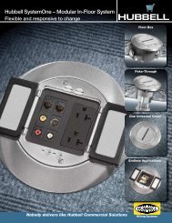
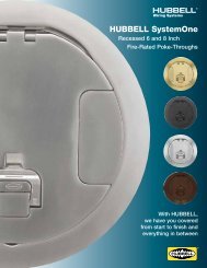
569C: Poke-Through Fittings<br />
• A poke-through device is used for penetration of building cabling through<br />
above-grade structural floors. Typically available in flush or raised configurations.<br />
• Maintain fire rating of the floor after installation.<br />
• Provide power and/or data service ports in limited capacity.<br />
Note: Consult a structural engineer before penetrating load-bearing floors.<br />
<strong>Hubbell</strong> SystemOne<br />
AV FRPT<br />
Large Capacity,<br />
FRPT<br />
Flush, FRPT<br />
569C: In-Floor Systems<br />
• Typically specifies embedded ducting in concrete or cellular floor configurations.<br />
• Design of these systems applies to new building constructions.<br />
569C: Multi-Tenant Pathways and Spaces<br />
• Specifies common equipment and telecommunications rooms.<br />
• Also includes provisions for shared access and service provider spaces.<br />
569C: Cable Trays and Wireways<br />
• Describes various pre-fabricated structures for supporting and routing cables.<br />
www.hubbell-premise.com<br />
V18
<strong>ANSI</strong>/<strong>TIA</strong>-570-B: Residential Telecommunications<br />
Cabling Standard<br />
This standard specifies cabling infrastructure for distribution of telecommunications services in single or multi-tenant dwellings.<br />
Residential cabling begins at the interface with the access provider, known as the Demarcation Point. The in-house cable distribution<br />
follows a star topology. Cabling for audio, security, and home controls have been added to this standard in the addenda listed below.<br />
There are two grades of residential cabling:<br />
• Grade 1: Minimum requirement<br />
- One 4-pair UTP Category 5e minimum cable and connecting hardware<br />
- One 75W series 6 coaxial cable and connecting hardware<br />
• Grade 2: Advanced multimedia (recommended)<br />
- Two 4-pair UTP Category 5e minimum cable and connecting hardware<br />
- Two 75W coaxial cables and connecting hardware<br />
- One pair of cabled multimode optical fibers (optional)<br />
V19<br />
www.hubbell-premise.com
<strong>ANSI</strong>/<strong>TIA</strong>-606-B: Administration Standard for<br />
Commercial Telecommunications Infrastructure<br />
This standard establishes basic guidelines for identification, labeling, and record keeping. These practices are essential for<br />
continued operation and maintenance of a cabled network. The advantages of identifying and documenting all elements of<br />
the cabling infrastructure are:<br />
• Improved traceability of the network connections, paths, and locations<br />
• Moves, adds and changes (MACs) are easily implemented<br />
• Maintenance and troubleshooting is simplified<br />
Key Elements of the Network that Require<br />
Identifier Labels and Records:<br />
• Connecting hardware and splices<br />
• Cables<br />
• Telecommunications pathways (conduit, firestops, etc.)<br />
• Telecommunications spaces (EF, ER, TR, WA)<br />
• Grounding and bonding locations (TMGB, TGB, TBB)<br />
• Equipment<br />
• Building<br />
• Outside plant (OSP) cables and pathways<br />
Four Classes of System Administration:<br />
• Class 1: single building, 1 TR<br />
• Class 2: single building, multiple TRs<br />
• Class 3: campus with OSP<br />
• Class 4: multi-campus/multi OSP<br />
Requirements for Identifiers<br />
• Identifiers should have a logical alphanumeric code.<br />
• The code number should link to detailed permanent records.<br />
• Standard 606-B color codes should be used for all crossconnect<br />
fields.<br />
606-B Color Coding<br />
Orange<br />
Green<br />
Purple<br />
White<br />
Gray<br />
Demarcation point (Pantone 150C) – Central Office<br />
Network connections on customer’s side (Pantone 353C)<br />
Common equipment (Pantone 246C) - PVBX, LANs<br />
1st level backbone – Main to Intermediate<br />
2nd level backbone (Pantone 422C) – Intermediate to Telecom<br />
T e c h n i c a l I n f o r m a t i o n<br />
Requirements for Records<br />
• Drawings and documents must be backed up and<br />
secured by the building administration.<br />
• Moves, adds and changes (MACs) must be<br />
documented with a change order.<br />
• MACs must be updated in the permanent records.<br />
• All identifier information must be cross-referenced in<br />
the permanent records.<br />
Blue<br />
Brown<br />
Yellow<br />
Red<br />
Horizontal cabling (closet end only) (Pantone 291C) – Work Area<br />
Inter-building backbone (Pantone 465C) – Campus Environment<br />
Auxiliary circuits (Pantone 101C) – Alarm, Security, etc.<br />
Key telephone systems (Pantone 184C)<br />
Requirements for Labels<br />
• All labels must use a traceable, permanent identifier.<br />
• Each cable and pathway must be labeled on both ends.<br />
• All labels shall meet UL969 legibility, defacement and<br />
adhesion requirements.<br />
• Station connections may be labeled on the face plate.<br />
• All jack, connector and block hardware can be labeled<br />
on the outlet or panel.<br />
www.hubbell-premise.com<br />
V20
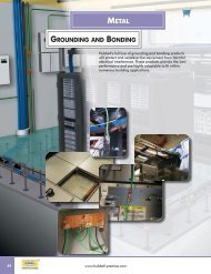
<strong>ANSI</strong>/<strong>TIA</strong>-607-B: Commercial Building Grounding and<br />
Bonding Requirements for Telecommunications<br />
Grounding Bar<br />
Cat No. MCCGBAR<br />
This standard specifies grounding and bonding design and distribution methods for commercial<br />
buildings. Proper earth grounding of the building structure and wiring is a requirement of the<br />
National Electric Code (NEC). Bonding all electrical and telecommunications equipment to the<br />
primary grounding electrode conductor (GEC) is essential for maximizing performance and safety.<br />
Note: Bonding to water pipes is now a code violation.<br />
Bonding telecommunications equipment, facilities, and cabling to the primary grounding electrode<br />
is accomplished using the following major elements:<br />
TBB<br />
TGB #3<br />
TGB #2<br />
TGB #1<br />
3rd Floor<br />
2nd Floor<br />
1st Floor<br />
• Grounding Electrode Conductor (GEC)<br />
• Bonding Conductor (BC)<br />
• Telecommunications Main Grounding Busbar (TMGB)<br />
• Telecommunications Bonding Backbone (TBB)<br />
• Telecommunications Grounding Busbar (TGB)<br />
BCT<br />
TMGB<br />
J-STD-607-A specifies the TMGB and TGB as a pre-drilled solid copper bar that extends the<br />
GEC for connecting the TBB. The TBB is typically a 6AWG stranded copper conductor that<br />
joins the copper TGBs on each floor of the building. A TGB is located in every TR and ER in the<br />
building. J-STD-607A also recommends surge protection devices for active telecommunications<br />
equipment.<br />
Note: The GEC is the largest grounding conductor and extends into the earth to a specified depth.<br />
GEC<br />
• The TBB should be continuous with no splices.<br />
• Connections to the TBB must use listed compression fittings.<br />
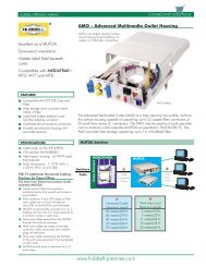
<strong>ANSI</strong>/<strong>TIA</strong>-862A: Building Automation Systems Cabling<br />
Standard for Commercial Buildings<br />
This standard establishes guidelines for structured cabling of low-voltage building automation systems (BAS). BAS wiring and control<br />
systems are converging with telecommunications infrastructures. NEC allows power-limited BAS systems to share the<br />
pathways and spaces with telecommunications infrastructure. LAN cabling is therefore not limited to voice and data transmission, and<br />
BAS applications present a new opportunity. Converging BAS with telecommunications are driving new industry standards. Designers<br />
must consider BAS cabling when sizing pathways and spaces in a building.<br />
Key Advantages of Converging BAS and Telecom Cabling<br />
• Project responsibility is reduced to a single team.<br />
• The building design and system administration is simplified.<br />
• Consolidation of service, equipment, and cabling facilities is achieved.<br />
• Common pathways and bonding points create a centralized infrastructure.<br />
• Cabling installation and practices of <strong>ANSI</strong>/<strong>TIA</strong>-<strong>568</strong>-C can be utilized.<br />
Basic Cabling Requirements for BAS<br />
• The horizontal cabling, installation, and BAS outlet connector shall meet <strong>ANSI</strong>/<strong>TIA</strong>-<strong>568</strong>-C.1.<br />
• A distributed or centralized star topology should be used.<br />
• Recognized cables for BAS horizontal and backbone:<br />
- 100 Ohm balanced twisted pair cable (<strong>ANSI</strong>/<strong>TIA</strong>-<strong>568</strong>-C.2)<br />
- Multimode or singlemode optical fiber (<strong>ANSI</strong>/<strong>TIA</strong>-<strong>568</strong>-C.3)<br />
• The BAS outlet may be connected from an HC or an optional CP.<br />
• Shared pathways of BAS/telecom cables must be code and capacity compliant.<br />
• For use with balanced twisted pair cable, the BAS device operating voltage and current are limited per <strong>ANSI</strong>/<strong>TIA</strong>-862A, Annex "A".<br />
• Separation of services is recommended in <strong>ANSI</strong>/<strong>TIA</strong>-862A, Annex "B". Shared cable sheath of BAS and telecommunications<br />
wiring is not recommended.<br />
V21<br />
www.hubbell-premise.com
<strong>ANSI</strong>/<strong>TIA</strong>-942A: Telecommunications Infrastructure<br />
Standards for Data Centers<br />
<strong>TIA</strong>-942A defines a data center as a building or portion of a building dedicated to housing large scale computer rooms and<br />
support facilities. Data centers are highly protected facilities that typically serve large private institutions or public service providers.<br />
Engineering design considerations for data centers include: architectural layout, space allocation, power, cooling, security, floor<br />
loading, telecommunications cabling distribution, and disaster avoidance/recovery.<br />
Data centers have a high level of fault tolerance, with (4) tiers of redundancy for all critical systems and support functions.<br />
Higher tiers are inclusive of lower tiers of redundancy, and provide increased levels of protection from service interruptions<br />
caused by specific events, such as fire or earthquakes. A Tier 4 facility provides maximum service availability, and is also the most<br />
costly construction.<br />
T e c h n i c a l I n f o r m a t i o n<br />
www.hubbell-premise.com<br />
V22
<strong>ANSI</strong>/<strong>TIA</strong>-1005-A: Industrial<br />
Telecommunication Infrastructure<br />
The official standard is developed by the <strong>TIA</strong>/TR-4.9 Industrial Telecommunications<br />
Infrastructure Subcommittee. This standard defines the requirements for cabling, connectors,<br />
pathways, and spaces designed to operate in harsh environments.<br />
For the Industrial Ethernet application, the basic performance and reliability sections of<br />
<strong>ANSI</strong>/<strong>TIA</strong>-<strong>568</strong>-C apply. Additional requirements are defined in <strong>TIA</strong>-1005A to incorporate<br />
harsh environments.<br />
TR-42.9 has established four conditions (MICE) <strong>TIA</strong>-<strong>568</strong>-C.0 that define the industrial<br />
environment:<br />
• Mechanical (shock, vibration, impact, etc.)<br />
• Ingress (contamination influx)<br />
• Climate (temperature, humidity, UV exposure, etc.)<br />
• Electromagnetic (conducted and radiated interference):<br />
Industrial Ethernet components are rated to withstand these conditions under specific levels<br />
of severity. The level of severity is determined by the application.<br />
• Ingress Protection (IP) codes are a two-digit code with the following criteria:<br />
- First digit: degree of protection from human contact with hazardous elements inside<br />
an enclosure, or from influx of foreign matter.<br />
- Second digit: degree of protection of equipment inside enclosures from the influx of water.<br />
Example: IP67 (6 = first digit, 7 = second digit)<br />
Note: The higher the number, the higher the degree of protection from human contact and influx of water.<br />
V23<br />
www.hubbell-premise.com
Standard UTP <strong>Wiring</strong> Conventions<br />
Horizontal UTP Cable and Patch Cords<br />
• Solid copper 4-pair 24 AWG UTP is specified for distribution cabling. Stranded UTP<br />
is specified for patch cords for flexibility. Shielded cable is not commonly used in the<br />
U.S. Splices bridge taps are not permitted.<br />
• Cable, connectors and patch cords shall be marked with the performance category.<br />
Always match performance categories of cables and components throughout the<br />
infrastructure.<br />
• All cable, cords and connecting hardware shall meet performance requirements<br />
of <strong>ANSI</strong>/<strong>TIA</strong>-<strong>568</strong>-C.2. <strong>Hubbell</strong> assures this compliance with all products and<br />
cable partners.<br />
COLOR CODING:<br />
white-blue/blue<br />
white-orange/orange<br />
white-green/green<br />
white-brown/brown<br />
Backbone UTP Cable<br />
• Solid copper 4-pair and 25-pair UTP is specified. An overall shield is optional.<br />
• Performance category markings and compliance to <strong>ANSI</strong>/<strong>TIA</strong>-<strong>568</strong>-C.1 and <strong>568</strong>-C.2 is required.<br />
• Circuits with incompatible signals should be partitioned in separate binder groups. Prior to making shared sheath circuit<br />
assignments, consult the equipment manufacturer for signal characteristics (i.e., frequency, amplitude, voltage, etc.).<br />
• Tip conductor insulation colors are matched to the binder group. Ring conductor insulation colors correspond the pair.<br />
T e c h n i c a l I n f o r m a t i o n<br />
Recognized Connector and <strong>Wiring</strong> Configurations<br />
• 8-position modular jack/plug<br />
• 8-position modular panel/plug<br />
• T<strong>568</strong>A wiring or T<strong>568</strong>B wiring options<br />
• Cat 5e, Cat 6 or Cat 6A recommended<br />
RJ-45 <strong>ANSI</strong>/<strong>TIA</strong>-<strong>568</strong> <strong>Wiring</strong> Conventions<br />
Two wiring standards were adopted. Both configurations are based on maximum transmission performance.<br />
T<strong>568</strong>A<br />
1: Green/White<br />
2: Green<br />
3: Orange/White<br />
4: Blue<br />
5: Blue/White<br />
6: Orange<br />
7: Brown/White<br />
8: Brown<br />
• Preferred method<br />
• Directly compatible with<br />
2-pair voice and token<br />
ring systems utilizing<br />
6-position connectors<br />
T<strong>568</strong>B<br />
1: Orange/White<br />
2: Orange<br />
3: Green/White<br />
4: Blue<br />
5: Blue/White<br />
6: Green<br />
7: Brown/White<br />
8: Brown<br />
• Optional method<br />
• AT&T ® standard<br />
• Directly compatible with<br />
AT&T phone systems<br />
AT&T ® is a registered trademark of AT&T Inc.<br />
www.hubbell-premise.com<br />
V24
Standard UTP <strong>Wiring</strong> Conventions<br />
USOC Conventions<br />
Universal Service Ordering Codes (USOC) are a series of Registered Jack (RJ) wiring configurations developed by the Bell System ®<br />
for connection of customer premises equipment to the network. FCC regulations govern these configurations.<br />
Color Coding<br />
Pair 1<br />
Pair 2<br />
Pair 3<br />
Pair 4<br />
TIP<br />
T1 – White/Blue<br />
T2 – White/Orange<br />
T3 – White/Green<br />
T4 – White/Brown<br />
Pair 1<br />
Pair 2<br />
Pair 3<br />
Pair 4<br />
RING<br />
R1 – Blue<br />
R2 – Orange<br />
R3 – Green<br />
R4 – Brown<br />
LAN <strong>Wiring</strong> Conventions<br />
Local area network (LAN) standards designed to operate over UTP specify pin/pair assignments on modular connectors for various<br />
signal transmission protocols. While <strong>ANSI</strong>/<strong>TIA</strong>-<strong>568</strong>A and <strong>568</strong>B conventions support all these designations, there are some cases<br />
where the user chooses to cable only the number of pairs required to support these applications.<br />
• 10 Mbps Ethernet<br />
over UTP<br />
• Uses only two pairs<br />
• 100 Mbps Ethernet<br />
• 4/16 Mbps token<br />
ring over copper<br />
• Uses only two pairs<br />
• 100 Mbps FDDI<br />
over copper<br />
• Uses only two pairs<br />
• 1000 Mbps<br />
Ethernet over UTP<br />
• Uses all four pairs<br />
V25<br />
www.hubbell-premise.com
Standard UTP <strong>Wiring</strong> Conventions<br />
Block <strong>Wiring</strong><br />
Standard color codes for 25-pair UTP cable are specified in the chart below.<br />
Wire/Color Code<br />
white/blue<br />
blue/white<br />
white/orange<br />
orange/white<br />
white/green<br />
green/white<br />
white/brown<br />
brown/white<br />
white/slate<br />
slate/white<br />
red/blue<br />
blue/red<br />
red/orange<br />
orange/red<br />
red/green<br />
green/red<br />
red/brown<br />
brown/red<br />
red/slate<br />
slate/red<br />
black/blue<br />
blue/black<br />
black/orange<br />
orange/black<br />
black/green<br />
green/black<br />
black/brown<br />
brown/black<br />
black/slate<br />
slate/black<br />
yellow/blue<br />
blue/yellow<br />
yellow/orange<br />
orange/yellow<br />
yellow/green<br />
green/yellow<br />
yellow/brown<br />
brown/yellow<br />
yellow/slate<br />
slate/yellow<br />
violet/blue<br />
blue/violet<br />
violet/orange<br />
orange/violet<br />
violet/green<br />
green/violet<br />
violet/brown<br />
brown/violet<br />
violet/slate<br />
slate/violet<br />
Tip and<br />
Ring<br />
Tip 1<br />
Ring 1<br />
Tip 2<br />
Ring 2<br />
Tip 3<br />
Ring 3<br />
Tip 4<br />
Ring 4<br />
Tip 5<br />
Ring 5<br />
Tip 6<br />
Ring 6<br />
Tip 7<br />
Ring 7<br />
Tip 8<br />
Ring 8<br />
Tip 9<br />
Ring 9<br />
Tip 10<br />
Ring 10<br />
Tip 11<br />
Ring 11<br />
Tip 12<br />
Ring 12<br />
Tip 13<br />
Ring 13<br />
Tip 14<br />
Ring 14<br />
Tip 15<br />
Ring 15<br />
Tip 16<br />
Ring 16<br />
Tip 17<br />
Ring 17<br />
Tip 18<br />
Ring 18<br />
Tip 19<br />
Ring 19<br />
Tip 20<br />
Ring 20<br />
Tip 21<br />
Ring 21<br />
Tip 22<br />
Ring 22<br />
Tip 23<br />
Ring 23<br />
Tip 24<br />
Ring 24<br />
Tip 25<br />
Ring 25<br />
Pair<br />
Number<br />
Pair 1<br />
Pair 2<br />
Pair 3<br />
Pair 4<br />
Pair 5<br />
Pair 6<br />
Pair 7<br />
Pair 8<br />
Pair 9<br />
Pair 10<br />
Pair 11<br />
Pair 12<br />
Pair 13<br />
Pair 14<br />
Pair 15<br />
Pair 16<br />
Pair 17<br />
Pair 18<br />
Pair 19<br />
Pair 20<br />
Pair 21<br />
Pair 22<br />
Pair 23<br />
Pair 24<br />
Pair 25<br />
50 Pin<br />
Positions<br />
26<br />
1<br />
27<br />
2<br />
28<br />
3<br />
29<br />
4<br />
30<br />
5<br />
31<br />
6<br />
32<br />
7<br />
33<br />
8<br />
34<br />
9<br />
35<br />
10<br />
36<br />
11<br />
37<br />
12<br />
38<br />
13<br />
39<br />
14<br />
40<br />
15<br />
41<br />
16<br />
42<br />
17<br />
43<br />
18<br />
44<br />
19<br />
45<br />
20<br />
46<br />
21<br />
47<br />
22<br />
48<br />
23<br />
49<br />
24<br />
50<br />
25<br />
66 or 110 Block<br />
Positions<br />
1<br />
2<br />
3<br />
4<br />
5<br />
6<br />
7<br />
8<br />
9<br />
10<br />
11<br />
12<br />
13<br />
14<br />
15<br />
16<br />
17<br />
18<br />
19<br />
20<br />
21<br />
22<br />
23<br />
24<br />
25<br />
26<br />
27<br />
28<br />
29<br />
30<br />
31<br />
32<br />
33<br />
34<br />
35<br />
36<br />
37<br />
38<br />
39<br />
40<br />
41<br />
42<br />
43<br />
44<br />
45<br />
46<br />
47<br />
48<br />
49<br />
50<br />
T e c h n i c a l I n f o r m a t i o n<br />
www.hubbell-premise.com<br />
V26
Audio Video Cabling<br />
AV line signal-level cabling and connectors are an integral part of structured horizontal cabling. Low voltage AV cabling may share<br />
the same pathways and wall outlet boxes with twisted pair or fiber data cabling. However, according to NEC 2005 Article 725.56(F),<br />
Class 1 audio power cables are prohibited from sharing the same pathway with any other Class 2 or Class 3 low voltage control<br />
wiring or network cables.<br />
Common AV Media Interface Connectors<br />
VGA 15-pin<br />
HDMI 15-pin<br />
RJ-45<br />
USB<br />
F-type<br />
RCA Composite<br />
RCA Component<br />
XLR<br />
RCA feed-through<br />
S-Video<br />
3.5mm Stereo Jack<br />
Types of AV Cable Media<br />
• Co-axial: RG6, RG59<br />
• DVI<br />
• 15-wire: VGA/HDMI<br />
• 2-wire audio: 26 to 14 AWG<br />
• 4-pair balanced UTP or FTP<br />
• USB<br />
• HDMI<br />
• Display port<br />
AV Cable Distance Limits and Other<br />
Considerations<br />
Total channel distances are limited for specific applications.<br />
USB channel lengths should not exceed 5.0 meters. Fire wire<br />
channel lengths should not exceed 4.5 meters. Horizontal<br />
cabling installations should allow for proper bend radius inside<br />
outlet boxes and behind walls.<br />
Shared pathways with other communications or low voltage<br />
cabling should be analyzed for any potential signal<br />
interference issues.<br />
Installation Tips<br />
• Do not exceed cable minimum bend radius when installing<br />
connectors. Contact cable manufacturer for bend radius<br />
specifications.<br />
• Soldering: Use the proper wire and solder temperature.<br />
Note: A "cold solder" will cause termination failures.<br />
• Screw terminal: Strip wire insulation to proper length.<br />
Capture all strands neatly during insertion.<br />
Two Basic Forms of Audio Signal<br />
• Analog audio: sound waves are modulated into a continuous<br />
electrical signal.<br />
• Digital audio: analog audio signal is encoded into digital bits.<br />
Two Basic Forms of Video Signal<br />
• Composite Video (low resolution)<br />
- Three color components delivered by one single cable;<br />
no audio content<br />
- Max resolution: 480i<br />
• Component Video (high resolution)<br />
- Red/Green/Blue (RGB) color components delivered by<br />
three separate cables, with audio content<br />
- Resolution up to 1080i<br />
HPW Product Compatibility Chart<br />
Port Configurations<br />
Product 1 2 3 4 6 9 12<br />
<strong>Hubbell</strong> iSTATION Module, 1U Flat 3 3 – – – – –<br />
<strong>Hubbell</strong> iSTATION Module, 1.5U Angled 3 3 – – – – –<br />
<strong>Hubbell</strong> iSTATION Module, 1.5U Recessed, Angled 3 3 – – – – –<br />
IFP Plates, 1-Gang 3 3 3 3 3 – –<br />
IFP Plates, 2-Gang – – – – 3 3 3<br />
Tamper-Proof Plates – – – 3 – – –<br />
Stainless Steel Plates, 1-Gang 3 3 3 3 3 – –<br />
Stainless Steel Plates, 2-Gang – – – – 3 3 3<br />
ISM Surface Mount Housings 3 3 – 3 3 – 3<br />
ISF Outlet Frames – 3 3 3 3 – –<br />
Quad 106 Outlet Frames – 3 – 3 – – –<br />
Furniture Plates – 3 – 3 – – –<br />
OFPPL Multimedia Plate – – – 3 – – –<br />
AMO Multimedia Housing 3 3 3 3 3 3 3<br />
UDX Jack Panels, 1U, 24-port 3 3 3 3 3 3 3<br />
UDX Jack Panels, 1U, 36-port 3 3 3 3 3 3 3<br />
V27<br />
www.hubbell-premise.com
Application Guides: Cabling Channel solutions<br />
Category 5e/6/6A Solution (without Consolidation Point)<br />
Applications Supported<br />
<br />
<br />
<br />
<br />
10BASE-T<br />
100BASE-T<br />
1000BASE-T<br />
10GBASE-T<br />
ISDN<br />
Token Ring<br />
ATM 155<br />
TP PMD<br />
VoIP<br />
<strong>Hubbell</strong> Solutions<br />
Product Cat 6A Solution Cat 6 Solution Cat 5e Solution<br />
Patch Cord PC6A Series PCX6 Series PCX5E Series<br />
Patch Panel HP6A Series P6E or PXJ Series P5E Series<br />
Plates IFP or IMF Series IFP or IMF Series IFP or IMF Series<br />
Jack(s) HJ6A HXJ6 HXJ5E<br />
Cable C6A Series C6 Series C5E Series<br />
T e c h n i c a l I n f o r m a t i o n<br />
Category 5e/6 Solution (with Consolidation Point)<br />
Applications Supported<br />
<br />
<br />
<br />
10BASE-T<br />
100BASE-T<br />
1000BASE-T<br />
ISDN<br />
Token Ring<br />
ATM 155<br />
TP PMD<br />
VoIP<br />
<strong>Hubbell</strong> Solutions<br />
Product Cat 6 Solution Cat 5e Solution<br />
Patch Cord PCX6 Series PCX5E Series<br />
Patch Panel P6E or PXJ Series P5E Series<br />
Plates IFP or IMF Series IFP or IMF Series<br />
Jack(s) HXJ6 HXJ5E<br />
or 110 Block 6110 Series 110BLK Series<br />
Cable C6 Series C5E Series<br />
www.hubbell-premise.com<br />
V28
Application Guides: Cabling Channel solutions<br />
25-Pair UTP<br />
Applications Supported<br />
10BASE-T<br />
100BASE-T<br />
<strong>Hubbell</strong> Solutions<br />
Product 100BASE-T 10BASE-T<br />
25-Pair Cable Assembly 525PS Series Customer Supplied<br />
Patch Panel<br />
MCCxx100BT19*<br />
Patch Cord PCX6 Series PCX5E Series<br />
Plate IFP or IMF Series IFP or IMF Series<br />
Jack(s) HXJ6 Series HXJ5E Series<br />
*xx changes with port capacity, length or style, depending on the product.<br />
Fiber Solutions<br />
Applications Supported<br />
1000BASE-SX/LX<br />
ATM (Fiber)<br />
10GBASE-SX/LX<br />
<strong>Hubbell</strong> Multimode Solutions<br />
Product<br />
Fiber Solution<br />
Patch Cord DFPSC Series<br />
Patch Panel FPR/FCR Series<br />
Plates IFP, IMF or AFP Series<br />
Fiber connector <strong>Hubbell</strong> OptiChannel or 2CLICK ® Series<br />
V29<br />
www.hubbell-premise.com
Product color chartS<br />
Jack Colors<br />
AL=Almond BK=Black B=Blue BN=Brown<br />
EI=Electric Ivory GL=Gold GY=Gray GN=Green<br />
LA=Light Almond OW=Office White OR=Orange P=Purple<br />
R=Red TI=Telco Ivory W=White Y=Yellow<br />
Plates, Frames, Modules, Snapfits and Surface Mount Box Colors<br />
AL=Almond BK=Black EI=Electric Ivory GY=Gray<br />
LA=Light Almond OW=Office White W=White<br />
T echnical i nformaT ion<br />
Fiber Adapter Colors for AMO Box<br />
AQ=Aqua BE=Beige BK=Black EI=Electric Ivory GN=Green<br />
OR=Orange R=Red Y=Yellow<br />
Patch Cord Colors<br />
BK=Black B=Blue GY=Gray GN=Green OR=Orange<br />
P=Purple R=Red W=White Y=Yellow<br />
Residential Flush Floor Box Covers<br />
Solid Brass Brass Plated Chrome Plated Copper Plated Nickel Plated Stainless Finish Almond Black Chestnut Brown<br />
<strong>Hubbell</strong> SystemOne Universal Covers<br />
Aluminum<br />
Finish<br />
Brass<br />
Finish<br />
Black<br />
Gray<br />
Ivory<br />
www.hubbell-premise.com<br />
V30