Operator's Maintenance Manual - BlueMoment
Operator's Maintenance Manual - BlueMoment
Operator's Maintenance Manual - BlueMoment
- No tags were found...

You also want an ePaper? Increase the reach of your titles
YUMPU automatically turns print PDFs into web optimized ePapers that Google loves.
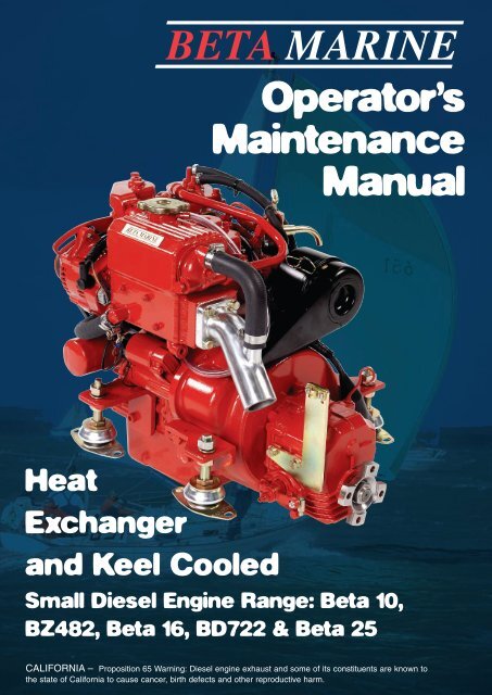
Operator’s<br />
<strong>Maintenance</strong><br />
<strong>Manual</strong><br />
Heat<br />
Exchanger<br />
and Keel Cooled<br />
Small Diesel Engine Range: Beta 10,<br />
BZ482, Beta 16, BD722 & Beta 25<br />
CALIFORNIA – Proposition 65 Warning: Diesel engine exhaust and some of its constituents are known to<br />
the state of California to cause cancer, birth defects and other reproductive harm.
Engine Details<br />
IMPORTANT – Please fill in details at moment of purchase – it really will<br />
help you! (and it will really help us specify the correct spare parts for you).<br />
Engine Type: Power: bhp Speed: rpm<br />
BETA WOC NO: K Engine Serial No:<br />
Gearbox Type: Serial No: Ratio :1<br />
Purchased from:<br />
Invoice No:<br />
Date:<br />
Date Commissioned:<br />
Specification / Special Details
Contents<br />
INTRODUCTION 2<br />
Engine Identification 2<br />
Initial Receipt of the engine 2<br />
Engine Storage 2<br />
SAFETY PRECAUTIONS 3<br />
TECHNICAL SPECIFICATIONS 4<br />
SECTION 1: GUIDELINES FOR OPERATION OF ENGINE<br />
Important checks prior to initial use 5<br />
Initial Start-up and Bleeding The Fuel System 5<br />
Starting/Stopping 6<br />
SECTION 2: MAINTENANCE AND SERVICE GUIDELINES<br />
<strong>Maintenance</strong> Schedule: 7<br />
Lubrication – Checking and changing oil 8<br />
Fuel System - Pumps, Filter, fuel/water separator 9<br />
Cooling - Fresh water system, Keel Cooling, Heat Exchanger 10<br />
Sea Water Pump, Heat Exchanger 12<br />
Belt Tensioning 13<br />
Air Filter 13<br />
Electrical 14<br />
Laying up - Winterising 14<br />
Troubleshooting 15<br />
Torque Settings 26<br />
SECTION 3: INSTALLATION GUIDELINES<br />
Engine Mounting 27<br />
Alignment - Drives, Flanges, Flexible Drives 27<br />
Exhausts & Bends 28<br />
Mounting Exhausts 28<br />
Fuel Supply 29<br />
Cooling 30<br />
Calorifier System 31<br />
Electrical installations 32<br />
Appendices –wiring diagrams and general arrangements 32<br />
Component identification at rear of manual. 63<br />
<strong>Maintenance</strong> Record 65<br />
1
OPERATION AND MAINTENANCE MANUAL FOR THE FOLLOWING<br />
BETA MARINE ENGINES BASED ON KUBOTA MINI SERIES<br />
Beta 10, BZ482, Beta 16 (BZ602),<br />
BD722 & Beta 25 (BD902)<br />
This manual has been compiled to<br />
provide the user with important<br />
information and recommendations<br />
to ensure a trouble free and<br />
economical operation of the<br />
engine.<br />
For further advice or technical<br />
assistance, application should be<br />
made to BETA MARINE LIMITED<br />
or its distributors.<br />
All information and<br />
recommendations given in this<br />
publication are based on the latest<br />
information available at the time of<br />
publication, and are subject to<br />
alteration at any time. The<br />
information given is subject to the<br />
company’s current conditions of<br />
Tender and Sale, is for the<br />
assistance of users, and is based<br />
upon results obtained from tests<br />
carried out at the place of<br />
manufacture and in vessels used<br />
for development purposes. We do<br />
not guarantee the same results will<br />
be obtained elsewhere under<br />
different conditions.<br />
ENGINE IDENTIFICATION<br />
NOTE: In all communications with<br />
the distributor or Beta Marine, the<br />
engine number, type, and W.O.C.<br />
number must be quoted.<br />
SAMPLE<br />
BETA 10, BZ482, BETA 16,<br />
BD722 & BETA 25<br />
The engine serial number is stamped<br />
above the fuel lift pump on the<br />
starboard side of the engine, and is<br />
shown on the rocker cover label.<br />
INITIAL RECEIPT<br />
OF THE ENGINE<br />
A full inspection of the engine must<br />
be made immediately on delivery to<br />
confirm that there is no damage. If<br />
there is any damage then write this<br />
clearly on the delivery note and<br />
inform your dealer or Beta Marine<br />
within 24 hours.<br />
ENGINE STORAGE<br />
The engine must be stored in a dry,<br />
frost free area and this is best done in<br />
its packing case. If storage is to be<br />
more than six months then the<br />
engine must be inhibited (contact<br />
your dealer or Beta Marine). Failure<br />
to inhibit the engine may result in the<br />
formation of rust in the injection<br />
system and the engine bores, this<br />
could invalidate the warranty.<br />
2
SAFETY PRECAUTIONS!<br />
A Keep the engine, gearbox<br />
and surrounding area clean,<br />
including the area immediately<br />
below the engine<br />
B DRIVES - Power Take Off<br />
Areas<br />
i) Gearbox Output Flange<br />
ii)<br />
The purpose of a marine diesel<br />
propulsion engine is to provide<br />
motive power to propel a vessel.<br />
Accordingly the gearbox output<br />
shaft rotates at between 300 and<br />
2400 rev/min. This flange is<br />
designed to be coupled to a<br />
propeller shaft by the installer and<br />
steps must be taken to ensure<br />
adequate guarding.<br />
Forward End Drive<br />
Engines are supplied with<br />
unguarded vee belt drives to<br />
power the fresh water pump and<br />
battery charging alternator. The<br />
installer must ensure that it is not<br />
possible for injury to occur by<br />
allowing accessibility to this area<br />
of the engine. The three pulleys<br />
run at high speed and can cause<br />
injury if personnel or clothing<br />
come in contact with the belts or<br />
pulleys, when the engine is<br />
running.<br />
iii) Power Take Off Shaft<br />
(Engine Mounted Option)<br />
C<br />
Shaft extensions are available as<br />
an option and rotate at between<br />
850 and 3600 rev/min. If<br />
contact is made with this shaft<br />
when the engine is running, injury<br />
can occur.<br />
EXHAUST OUTLET<br />
Diesel marine propulsion engines<br />
emit exhaust gases at very high<br />
temperatures - around 400-<br />
500°C. Engines are supplied with<br />
either wet exhaust outlet (water<br />
injection bend) or dry outlet (dry<br />
exhaust stub) - see option list. At<br />
D<br />
the outlet next to the heat<br />
exchanger/header tank, the<br />
exhaust outlet can become very<br />
hot and if touched, can injure.<br />
This must be lagged or avoided by<br />
ensuring adequate guarding. It is<br />
the responsibility of the installer to<br />
lag the exhaust system if a dry<br />
system is used. Exhaust gases<br />
are harmful if ingested, the<br />
installer must therefore ensure that<br />
exhaust lines are lead overboard<br />
and that leakage in the vessel<br />
does not occur.<br />
FUEL<br />
i) Fuel Lines<br />
ii)<br />
E<br />
F<br />
Diesel engines are equipped with<br />
high pressure fuel injection<br />
pumps, if leakages occur, or if<br />
pipes fracture, fuel at a high<br />
pressure can harm personnel.<br />
Skin must be thoroughly cleaned<br />
in the event of contact with diesel<br />
fuel.<br />
Fuel Supply Connections<br />
Engines are supplied with 8 mm<br />
compression fittings. The installer<br />
must ensure that when<br />
connections are made, they are<br />
clean and free of leaks.<br />
OIL<br />
The Beta propulsion is supplied<br />
with 2 dipsticks, one for the<br />
engine and one for the gearbox.<br />
Ensure dipsticks are returned and<br />
secure after checking, if not oil<br />
leaks can cause infection when<br />
touched. All oil must be removed<br />
from the skin to prevent infection.<br />
SCALDING<br />
An engine running under load will<br />
have a closed circuit fresh water<br />
temperature of 85° to 95°C. The<br />
pressure cap on the top of the<br />
heat exchanger must not be<br />
removed when the engine is<br />
running. It can only be removed<br />
when the engine is stopped and<br />
has cooled down.<br />
G<br />
TRANSPORTATION/LIFTING<br />
Engines are supplied on<br />
transportable pallets. Lifting eyes<br />
on engines are used for lifting<br />
engine and gearbox assembly<br />
only, not the pallet and<br />
associated kit.<br />
GENERAL DECLARATION<br />
This machinery is not intended to<br />
be put into<br />
service until it has been<br />
incorporated into or with other<br />
machinery. It is the responsibility of<br />
the purchaser/installer/owner, to<br />
ensure that the machinery is<br />
properly guarded and that all<br />
necessary health and safety<br />
requirements, in accordance with<br />
the laws of the relevant country, are<br />
met before it is put into service.<br />
Signed:<br />
J A Growcoot, C.E.O,<br />
Beta Marine Limited<br />
NOTE: Recreational Craft<br />
Where applicable, the<br />
purchaser/installer/owner and operator<br />
must be responsible for making sure<br />
that the Recreational Craft Directive<br />
94/25/EC is complied with.<br />
3
TECHNICAL SPECIFICATIONS<br />
MINI SERIES – STANDARD ENGINES<br />
BETA 10 BZ482 Beta 16 BD722 Beta 25<br />
Cylinder 2 2 2 3 3<br />
Bore (mm) 67 67 72 67 72<br />
Stroke (mm) 68 68 73.6 68 73.6<br />
Displacement (cc) 479 479 599 719 898<br />
Combustion 3 Vortex E-TVCS<br />
Cooling Water<br />
Starter voltage (V) 12<br />
Starter output (kW) 0.8<br />
Starter alternator output (Amps) 40 (standard)<br />
Glow plug resistance (each) 1Ω<br />
Engine speed (RPM) 3,000 3,600<br />
Power output to ISO3046 (BHP) 10.0 13.3 16.7 20.0 24.8<br />
Declared power ISO8665 (kW) 7.4 8.7 11.0 13.1 16.3<br />
Fuel timing BTDC 21°<br />
Capacity of standard sump approx (litres) 2.0 - 2.5 2.4 - 2.9 3.1 - 3.8 3.7 – 4.5<br />
Capacity of shallow sump approx (litres) 2.2 2.6 3.4 3.8<br />
Nett dry weight with gearbox (kg) 87.2 94.1 101.7 110.6<br />
Fuel Diesel oil class A1 / A2<br />
Coolant 33%-50% maximum antifreeze / water<br />
Coolant capacity approx (H/E litres) 2.25 3.00 3.25<br />
Min. recommended battery capacity 12V, 40Ah 12V, 75Ah<br />
Maximum Angle of Installation: Trim 15°, Roll 30° (intermittent)<br />
Rotation: ANTI CLOCK ON FLYWHEEL, CLOCKWISE ON OUTPUT GEARBOX FLANGE FOR USE WITH RIGHT HAND PROP IN AHEAD<br />
Diesel fuel must conform to BS2869-1970 class A1 or A2. The fuel must be a distillate, and not a residual oil or blend.<br />
Lubricant: Engine - Engine oil must meet MIL-L-2104C (see section 2 for details)<br />
Gearbox - see operator’s manual for the gearbox oil type and capacity<br />
Oil pressure – minimum (tickover) 0.5 bar<br />
Power outputs: These comply with BS EN ISO 8665:1996 crankshaft power<br />
Note: Declared Powers to ISO8665:1995<br />
1. The declared powers are at the same engine speed as the ISO 3046 figures. This speed is the speed related to the outputs / powers shown.<br />
2. Declared powers are at the gearbox coupling (coupling to the propeller shaft) as per clause 3.2.1 with standard specifications as per our current price lists.<br />
Additional accessories or alternative gearboxes may affect the declared powers.<br />
3. Operation at parameters outside the test parameters may affect the outputs / powers which in any case are subject to the ISO tolerance bands.<br />
4
SECTION 1<br />
GUIDELINES FOR OPERATION OF ENGINE<br />
IMPORTANT CHECKS PRIOR<br />
TO INITIAL USE<br />
1. Generally, a new engine has the<br />
oil and anti-freeze removed after<br />
the works test. Fill the engine<br />
with the correct oil and antifreeze<br />
(see sections on ENGINE<br />
OIL and COOLING). Check<br />
gearbox oil level - see separate<br />
operator’s hand book.<br />
2. Ensure the engine is free to turn<br />
without obstructions.<br />
3. Ensure battery is fully charged<br />
and connected (the isolator is in<br />
the ‘ON’ position).<br />
4. Ensure Morse speed and gearbox<br />
cables are fitted correctly and that<br />
cable travel lengths are correct.<br />
Gear selection lever –all<br />
mechanical gearboxes: care must<br />
be taken to ensure that the<br />
remote control cable is adjusted<br />
so that the selector lever on the<br />
gearbox moves FULL travel and<br />
brought “hard up” against its end<br />
stop in both directions. Failure to<br />
achieve the correct adjustment<br />
will reduce efficiency of the<br />
clutch and may cause slippage at<br />
low revs. Warranty will not be<br />
accepted on gearboxes returned<br />
in the warranty period for failure<br />
due to incorrect adjustment.<br />
5. Ensure engine is out of gear with<br />
1/3 throttle - see single lever<br />
control instruction manual.<br />
6. Open the fuel stopcock and bleed<br />
the fuel water separator of air as<br />
shown in manufacturers<br />
literature.<br />
7. Fuel should now be at the fuel lift<br />
pump, see diagram 1a.<br />
8. Open the sea cock.<br />
INITIAL STARTUP AND<br />
BLEEDING THE SYSTEM<br />
(a) Open fuel bleed screw on<br />
injection pump by 1 1 /2 turns. See<br />
diagram 1a.<br />
(b) Move hand priming lever on fuel<br />
lift pump up and down until fuel<br />
with no bubbles comes out of the<br />
bleed screw.<br />
(c) Shut/tighten the bleed screw.<br />
Clean area thoroughly with tissue<br />
paper.<br />
(d) Continue to hand prime for 30<br />
seconds to push fuel through the<br />
fuel pump.<br />
(e) Start engine (see normal starting).<br />
Note the engine may have to be<br />
turned over with the starter for a<br />
few seconds before it fires. Do<br />
not run the starter for more than<br />
20 seconds. If the engine has not<br />
started after 20 seconds then<br />
disengage the starter and<br />
continue to hand prime for a<br />
further 30 seconds, then repeat.<br />
(f) If engine does not start after 3<br />
attempts then allow 5 minutes for<br />
the starter to cool down before<br />
repeating (a) to (e).<br />
Note: The starter windings can<br />
be burnt out with continuous<br />
cranking<br />
CAUTION<br />
To avoid personal injury:<br />
• Do not bleed a hot engine as this<br />
could cause fuel to spill onto a hot<br />
exhaust manifold creating a danger<br />
of fire.<br />
• Do not mix gasoline or alcohol<br />
with diesel fuel. This mixture can<br />
cause an explosion.<br />
• Do not get diesel on the flexible<br />
mounts – they will deteriorate<br />
rapidly if soaked in diesel.<br />
• All fuel must be removed from skin<br />
to prevent infection.<br />
Diagram 1a<br />
5
NORMAL STARTING (ALL BETA<br />
PANELS WITH SILVER KEYSWITCH)<br />
With the engine out of gear, set speed<br />
control lever to 1/3 throttle. Turn key<br />
anti-clockwise to HEAT* (A) position<br />
and hold for ten seconds, turn key<br />
clockwise to RUN (C) position. At this<br />
stage the instrument panel should<br />
illuminate, an alarm buzzer will sound<br />
and two (or three*) red warning lights<br />
will illuminate:<br />
STARTER BATTERY CHARGE<br />
DOMESTIC BATTERY CHARGE* (D<br />
in battery symbol - AB & C PANELS<br />
ONLY)<br />
*(Note: this will only illuminate if 2nd<br />
alternator is fitted)<br />
OIL PRESSURE and green POWER<br />
ON / RUN LIGHT (this will stay on)<br />
Turn to START<br />
(D) position and<br />
engine will<br />
motor, hold in<br />
position until<br />
engine fires (see<br />
initial start-up<br />
A<br />
HEAT<br />
B<br />
OFF<br />
C<br />
RUN<br />
section for maximum time starter can<br />
be used).<br />
D<br />
START<br />
Release key (when engine has started)<br />
to RUN position. Ensure alarm buzzer<br />
is not sounding and that warning<br />
lights are extinguished. If one or both<br />
of the alternator warning lights are still<br />
on, then increase engine speed to<br />
excite the alternator - then return to<br />
idle. The battery charge lights should<br />
then go out. The run light will remain<br />
on (green LED).<br />
Note: for panels without keyswitches<br />
see seperate instruction sheet<br />
(page 24).<br />
STOPPING<br />
Every propulsion engine is fitted with a<br />
stop solenoid which is energised to<br />
stop. To stop engine simply press stop<br />
push button, hold in until engine<br />
stops, then turn key from ‘RUN’ to<br />
‘OFF’ position.<br />
When leaving the boat for an extended<br />
period,<br />
• Turn off sea-cock (heat exchanger<br />
cooled engines).<br />
• Turn off battery isolator.<br />
Do not turn the key to the off<br />
position when the engine is running.<br />
This will not allow the alternator to<br />
charge.<br />
*WARNING<br />
Do not leave the key in ‘HEAT’ position<br />
for more than 15 seconds - this will<br />
damage the heater plugs and eventually<br />
lead to poor starting.<br />
Do not depress stop button for more<br />
than 10 seconds as this will lead to<br />
overheating and failure of the solenoid.<br />
NOTES FOR ALL PANEL TYPES:<br />
Do not depress the stop button for<br />
more than ten seconds as this will<br />
lead to overheating and failure of the<br />
solenoid.<br />
Stop lever<br />
The Mini range of engines are<br />
equipped with a mechanical stop lever<br />
in the event of electrical system failure.<br />
This lever is located on the starboard<br />
side of the engine above the speed<br />
control lever. See illustration below:<br />
Speed lever<br />
6
SECTION 2<br />
MAINTENANCE SCHEDULE<br />
DAILY OR EVERY 8 HOURS<br />
RUNNING<br />
• Check engine oil level.<br />
• Check gearbox oil level.<br />
• Check coolant level.<br />
• Check battery fluid.<br />
• Check drive belt tension<br />
• Ensure raw water inlet strainer is<br />
clear.<br />
• Check stern gland lubrication.<br />
• Drain off any water in fuel water<br />
separator.<br />
AFTER THE FIRST 25 HOURS<br />
RUNNING<br />
• Change gearbox lubricant (See<br />
separate gearbox manual).<br />
• Check that all external nuts, bolts<br />
and fastenings are tight. See table<br />
for torque values. Special attention<br />
should be paid to the flexible<br />
mount lock nuts, these should be<br />
checked for tightness, starting<br />
with lower nut first in each case.<br />
If the lower nuts are found to be<br />
very loose, then the alignment of<br />
the shaft to the gearbox half<br />
coupling should be re-checked.<br />
Poor alignment due to loose<br />
flexible mount nuts will cause<br />
excessive vibration and knocking.<br />
• Check the belt tension on any<br />
second alternators fitted and<br />
adjust –see page 11<br />
• Check ball joint nyloc nuts for<br />
tightness on both gearbox and<br />
speed control levers. Grease both<br />
fittings all over.<br />
AFTER FIRST 50 HOURS<br />
• Change engine lubricating oil.<br />
• Change oil filter.<br />
• Check for leaks on header tank<br />
tubestack. Tighten end cap bolt if<br />
required.<br />
• Drain off any water in fuel/water<br />
separator.<br />
EVERY 150 HOURS<br />
• If shallow sump (option) is fitted,<br />
change engine lubricating oil and<br />
filter.<br />
EVERY YEAR -OR EVERY 250<br />
HOURS IF SOONER<br />
• Change engine lubricating oil<br />
(standard sump)<br />
• Change lubricating oil filter<br />
• Check air cleaner element<br />
• Check sea water pump impeller<br />
and change if worn.<br />
• Check wasting anode condition,<br />
replace when necessary. In some<br />
environments this may be 6<br />
montly or less.<br />
• Remove heat exchanger tube<br />
stack, by undoing the bolt each<br />
end of the tube stack. Remove<br />
end cover, pull out tube stack and<br />
clean. Replace rubber ‘O’ rings<br />
and re-assemble. Immediately<br />
engine is started check for leaks.<br />
• Spray the key switch with WD40<br />
or equivalent to lubricate the<br />
barrel.<br />
• Check that all external nuts, bolts<br />
and fastenings are tight. See table<br />
for torque values.<br />
• Check ball joint nyloc nuts for<br />
tightness on both gearbox and<br />
speed control levers. Grease both<br />
fittings all over.<br />
EVERY 750 HOURS<br />
• As every 250 hours plus the<br />
following:-<br />
• Change air cleaner element.<br />
• Change fuel filter.<br />
• Change antifreeze.<br />
• Change gearbox oil.<br />
• Check electrical equipment,<br />
condition of hoses and belts,<br />
replace as necessary.<br />
7
LUBRICATION<br />
Engine oil: Engine oil should be MIL-<br />
L-2104C or have properties of API<br />
classification CC/CD/CE grades. The<br />
following table gives grades of oil<br />
required for various ambient<br />
temperatures.<br />
Note: A good quality 15W/40<br />
mineral or multigrade oil as used in<br />
most diesel car engines will meet<br />
these requirements. Do not use<br />
‘Turbo Diesel Oil’ or additives.<br />
CHECKING ENGINE OIL<br />
LEVEL<br />
For quantities of oil required see<br />
section marked ‘Technical<br />
Specification’, Page 4<br />
When checking the engine oil level,<br />
do so before starting, or more than<br />
five minutes after stopping.<br />
1. To check the oil level, draw out<br />
the dipstick, wipe it clean, reinsert<br />
it, and draw it out again.<br />
Check to see that the oil level lies<br />
between the two notches.<br />
2. If the level is too low, add new oil<br />
to the specified level - Do not<br />
overfill,<br />
IMPORTANT<br />
When using an oil of different make<br />
or viscosity from the previous one,<br />
drain old oil. Never mix two different<br />
types of oil. Engine oil should be<br />
changed after first 50 hours running<br />
time and then every year or every<br />
250 hours if sooner. Oil filter is a<br />
cartridge type mounted on the port<br />
side of the engine.<br />
AMBIENT TEMP SINGLE GRADE MULTI GRADE<br />
-30°C TO 0°C SAE 10W S AE 10W/30<br />
-15°C TO +15°C SAE 20W SAE 15W/40<br />
0°C TO +30°C SAE 30 SAE 15W/40<br />
25°C AND ABOVE SAE 30 SAE 15W/40<br />
CHANGING ENGINE OIL<br />
(1) Run the engine for 10 minutes to<br />
warm up the oil.<br />
(2) Your engine is provided with a<br />
sump drain pump (option on<br />
Beta Ten, see note below).<br />
Unscrew the end cap on the<br />
end of the pump (if fitted),<br />
turn the tap to ‘on’. Use the<br />
hand pump as shown to<br />
pump out the oil into a<br />
bucket. Turn the tap to off<br />
position and replace end<br />
cap. See diagram 2c.<br />
(3) Unscrew the oil filter and<br />
replace with a new one. See<br />
diagram 2d.<br />
Note: It is best to have a<br />
plastic bag wrapped round<br />
the filter to catch any oil left<br />
in the system. (Always keep<br />
your bilges clean!) Before<br />
screwing in the new filter<br />
spread a thin film of oil<br />
round the rubber gasket to<br />
ensure a good seal and<br />
screw in – hand tight.<br />
Note: On the Beta Ten not fitted with<br />
a sump drain pump the engine oil<br />
must be drained off by unscrewing<br />
the sump drain plug (see diagram<br />
100-00030 at rear of book). This is<br />
Fig. 2a<br />
Oil goes in here<br />
best done with the oil filler cap<br />
removed. Replace the plug and<br />
tighten firmly.<br />
(4) Fill the engine with new oil as<br />
described above.<br />
Sump pump<br />
End Cap<br />
Fig. 2c<br />
Tap<br />
Fig. 2b. Dip stick<br />
Fig. 2d<br />
Oil filter<br />
8
CHECKING GEARBOX OIL LEVEL<br />
(1) The gearbox is fitted with a<br />
dipstick and oil filler plug, see fig<br />
2e.<br />
(2) Each engine is supplied with a<br />
gearbox operators manual which<br />
specifies the type of lubricating<br />
oil to be used, the capacity and<br />
frequency of changing of the oil.<br />
(3) New engines are normally<br />
supplied with the gearbox<br />
topped up with lubricant but<br />
Check the level before<br />
starting the engine for the first<br />
time.<br />
(4) The oil can be changed via the<br />
drain plug at the bottom of the<br />
box or sucked out with a hand<br />
pump via the filler plug.<br />
(5) A guide to the type of oil to be<br />
used is as follows:<br />
Gearbox Lubricant Capacity (approx)<br />
TMC40 Use ATF Oil 0.2 litres<br />
PRM 80/ 120 Use Engine Oil 15W40 0.6 / 0.8 litres<br />
ZF5M / ZF10M Use ATF Oil 0.3 / 0.35 litres<br />
TTMC 35A-2 Use Engine Oil SAE 30 (HD) 0.65 litres<br />
Note: ATF is Automatic Transmission Fluid<br />
Dip<br />
stick<br />
Oil<br />
filler<br />
plug<br />
Oil drain<br />
plug<br />
Fig 2e<br />
FUEL SYSTEM<br />
(see page 29 for a typical installation)<br />
IMPORTANT<br />
• Always fit a fuel/water separator<br />
in the fuel supply system. Water<br />
in the fuel can seriously damage<br />
the injection system.<br />
• If a fuel supply shutoff valve is<br />
fitted do not use a taper tap, only<br />
use a ball valve tap. The ball<br />
valve type are more reliable and<br />
less likely to let air into the fuel<br />
system.<br />
• Be sure to use a strainer when<br />
filling the fuel tank. Dirt or sand<br />
in the fuel may cause trouble in<br />
the fuel injection pump.<br />
• Always use diesel fuel.<br />
• Do not use kerosene which is<br />
very low in cetane rating, and<br />
adversely affects the engine.<br />
• Be careful not to let the fuel tank<br />
become empty, or air can enter<br />
the fuel system, necessitating<br />
bleeding before next engine start.<br />
• The fuel lift pump will only lift<br />
fuel through 0.25 metres. If this<br />
is insufficient then an electric fuel<br />
lift pump must be fitted.<br />
FUEL FILTER REPLACEMENT<br />
1. The fuel filter is a spin on type.<br />
Remove by turning anti-clockwise<br />
when viewed from below.<br />
2. Replace the fuel filter cartridge<br />
every 750 hours. See fig. 2g.<br />
Fig. 2g<br />
3. Apply fuel oil thinly over the<br />
gasket and tighten into position -<br />
hand tight.<br />
4. Bleed as detailed - see initial start up.<br />
5. Check for leaks.<br />
6. Do not get fuel on the flexible<br />
mounts.<br />
Filter bleed screw<br />
Fuel filter<br />
9
COOLING<br />
The Mini Series range of engines are<br />
normally fresh water cooled. This<br />
water circulates through the engine<br />
and on to a heat exchanger where it<br />
is cooled by sea water which is<br />
pumped through the cooling tubes.<br />
The sea water is then injected into<br />
the exhaust system (see diagram<br />
‘heat exchanger cooled’ below).<br />
KEEL COOLING is an option. In this<br />
system the freshwater is pumped<br />
through the engine and then through<br />
a cooler built into the side of the boat<br />
where it is cooled by heat transfer<br />
before returning to the engine .<br />
The ideal keel cooling tank should<br />
have:<br />
a. Baffle continuously welded to<br />
outer skin and close fitting on<br />
inner skin<br />
b. Be thin in section to allow good<br />
mixing of the water over the cool<br />
outer surface.<br />
c. Air bleed valves should be fitted<br />
on both ends. (See page 30).<br />
Heat Exchanger Cooled<br />
Keel Cooled -Note efficient cooling tanks are side<br />
mounted, see page 31<br />
FILLING THE FRESHWATER SYSTEM<br />
New engines are supplied with the<br />
freshwater drained off. The following<br />
instructions must be followed to fill<br />
the system.<br />
(a) Mix up in a clean bucket a 30 to<br />
50% antifreeze to freshwater<br />
solution. For the volume required<br />
see technical specification page 4.<br />
(b) Check that the drain tap or plug<br />
is turned off. (see fig 2l) (Note<br />
BZ482 and B10 engines with<br />
sump drain pump are fitted with<br />
a plug).<br />
(c) Fill engine with freshwater/anti<br />
freeze solution through the top of<br />
the heat exchanger or header<br />
tank with the filler cap removed.<br />
(see fig 2m).<br />
(d) Fill header tank to the top of the<br />
filler neck and replace cap. Press<br />
down firmly on filler cap and<br />
hand tighten in a clockwise<br />
direction.<br />
Note: For keel cooled engines a<br />
much larger quantity of<br />
freshwater/anti-freeze solution is<br />
required depending on the size of the<br />
keel cooling tank – refer to the<br />
builder.<br />
(e) Run the engine for 5 minutes on<br />
no load (out of gear) and check<br />
coolant level. Top up as<br />
necessary.<br />
(f) Check system for leaks.<br />
Note: For keel cooled engines it<br />
is very important to bleed all the<br />
air out of the system before the<br />
engine is run on load (check with<br />
builder’s instructions).<br />
(g) If a calorifier is fitted care must<br />
be taken to see that this is also<br />
full of coolant and all the air is<br />
expelled. (See calorifier fitting<br />
notes under Section 3).<br />
(h) Run the engine on one third load<br />
for 15 minutes, preferably with<br />
the boat tied up. As the system<br />
warms up coolant may be<br />
expelled from the overflow pipe<br />
into the bilge. Stop the engine<br />
and allow the engine to cool<br />
down before removing the<br />
pressure cap and top up the<br />
coolant to 1” below the filler<br />
neck.<br />
10
Fig. 2l<br />
IMPORTANT<br />
Removal of the pressure cap when<br />
the engine is hot can cause severe<br />
injury from scalding hot water under<br />
pressure. Always allow the engine to<br />
cool and then use a large cloth when<br />
turning the cap anti-clockwise to the<br />
stop. This allows the pressure to be<br />
released. Press firmly down on the<br />
cap and continue to turn<br />
anticlockwise to release the cap.<br />
(i) Repeat (h) if<br />
coolant level is more than 1 inch<br />
below the base of the filler neck<br />
when the engine has cooled<br />
down.<br />
(j) Run engine on 2/3 full load for<br />
20 minutes, check for leaks and<br />
repeat (i).<br />
(k) Anti-freeze solutions should be<br />
drained off every 2 years and<br />
replaced with a new solution.<br />
Fig. 2m<br />
Note: When draining fresh water<br />
system, ensure the engine has cooled<br />
sufficiently to prevent scalding from<br />
hot pressurised water. Prior to<br />
draining a cold engine, remove the<br />
filler cap from the header tank and<br />
then open the water drain tap. This<br />
allows the water to drain freely from<br />
the system.<br />
YACHTS AND LAUNCHES<br />
WITH HEAT EXCHANGER<br />
COOLING<br />
It is essential that a 33% to 50%<br />
anti-freeze/water mixture is used.<br />
This not only stops freezing up in<br />
winter, but it prevents overheating<br />
and corrosion.<br />
The warranty is invalid unless the<br />
correct ratio is used.<br />
CANAL BOATS WITH KEEL<br />
COOLER<br />
A 33% anti-freeze to water mixture is<br />
recommended to give protection<br />
against very cold winter temperature of<br />
minus 15°C. This anti-freeze will also<br />
give the engine internal protection<br />
against corrosion. For keel cooled<br />
engines the total system capacity must<br />
be taken into consideration, ie engine<br />
volume plus skin tank/keel cooler<br />
volume.<br />
Concentration of ethylene should not<br />
exceed 50%.<br />
The anti-freeze in the fresh water<br />
system enables the boiling point of<br />
water to rise to 124°C with a 13 psi<br />
pressure cap fitted. The water<br />
temperature alarm switch will however<br />
be activated at 95° to 100°C. If no<br />
anti-freeze or a very weak solution is<br />
used, then the water temperature<br />
switch may not be activated before<br />
coolant is lost.<br />
11
SEA WATER PUMP AND COOLING SYSTEM - (Heat exchanger-cooled engines)<br />
CAUTION<br />
Before working on the sea water<br />
system ensure that the sea cock is<br />
in the off position.<br />
(1) It is very important that the<br />
correct sea water flow is<br />
maintained to cool the closed<br />
circuit system of the engine. The<br />
key component in this system is<br />
the sea water pump impeller.<br />
This should be checked every<br />
year by removing the circular<br />
plate (see fig. 2h)<br />
(2) Withdraw the rubber impeller<br />
from its drive shaft as shown.<br />
See diagram 2i.<br />
(3) Check impeller for cracks in the<br />
rubber, excessive wear or lost<br />
vanes. Replace with a new<br />
impeller as necessary.<br />
Note: If any pieces of rubber<br />
impeller are missing then they must<br />
be found as they are most likely to be<br />
trapped in the entrance to the heat<br />
exchanger cooling stack. See<br />
‘Cleaning Tube Stack’.<br />
Fig. 2h<br />
Fig. 2i<br />
CLEANING THE HEAT EXCHANGER TUBE STACK AND REPLACING WASTING ZINC ANODE<br />
(1) The wasting zinc anode should<br />
be checked every six months and<br />
replaced every year or as<br />
necessary. The anode is attached<br />
to the bolt inserted in the aft end<br />
cap of the heat exchanger. See<br />
fig. 2j.<br />
(2) Unscrew the bolt and replace the<br />
complete unit with a new one.<br />
(3) Check for leaks.<br />
(4) It is possible for fine sea weed<br />
and other debris to get past the<br />
inlet filter and into the tube stack.<br />
This should be removed and<br />
cleaned. See fig. 2k.<br />
(5) Drain off coolant into a bucket.<br />
(6) Unscrew the 2 end cap retaining<br />
bolts (one each end of the tube<br />
stack). Remove the ‘O’ rings and<br />
pull out tube stack. Clean tube<br />
stack and end caps.<br />
(7) Re-assemble using new ‘O’ rings.<br />
Do not overtighten end cap bolts<br />
and make sure the tube stack is<br />
the right way round.<br />
(8) Re-fill engine with water/antifreeze<br />
solution and run engine up<br />
to temperature to check for leaks.<br />
Zinc<br />
Anode<br />
Fig. 2j<br />
Fig. 2k<br />
12
BELT TENSION<br />
40 AMP ALTERNATOR<br />
WARNING<br />
Belt tension must only be checked<br />
with the engine switched off.<br />
(1) The Mini Series range of engines<br />
are normally fitted with a single<br />
belt to drive the 40 amp battery<br />
charging alternator and the fresh<br />
water circulating pump.<br />
(2) The belt tension is adjusted by<br />
swinging the alternator outboard<br />
as it pivots on its power support<br />
bolt.<br />
(3) With the engine stopped, loosen<br />
the support bolts and the link<br />
adjusting bolt.<br />
(4) Push alternator outboard to<br />
tension and tighten link bolt.<br />
Check that the depression of the<br />
belt at position shown is<br />
approximately 1 /2” or 12 mm<br />
when pushed down firmly by<br />
thumb. Tighten support bolts.<br />
(5) Belt tension should be regularly<br />
checked especially during the first<br />
20 hours of running in a new<br />
belt, as stretching occurs.<br />
65 AMP ALTERNATOR (OPTION)<br />
Link adjust bolt<br />
The same method, as outlined above<br />
applies, but final tensioning must be<br />
by hand only. Over tensioning will<br />
cause premature failure of<br />
components<br />
Support bolt<br />
AIR INTAKE FILTER<br />
These engines are fitted with an air intake filter which should be checked every season and changed every 2 years or<br />
sooner if badly clogged.<br />
1 2<br />
3<br />
13
MAINTENANCE - ELECTRICAL<br />
WARNING<br />
Under NO circumstances should the<br />
battery be disconnected or switched<br />
off when the engine is running. This<br />
will seriously damage the alternator<br />
PANELS AND WIRING<br />
See installation notes, page 32.<br />
GENERAL MAINTENANCE<br />
(1) The panel must be protected<br />
from rain and sea water, see<br />
installation. Sea water entering<br />
the key switch will eventually<br />
cause corrosion and could result<br />
in the starter motor being<br />
permanently energised and<br />
burning out. Spray key switch<br />
every month with WD 40 or<br />
equivalent.<br />
(2) Check batteries for acid level and<br />
top up if required. For low<br />
maintenance and ‘gel’ batteries<br />
see manufacturers instructions.<br />
(3) Loose spade terminal<br />
connections are the most<br />
common cause for electrical<br />
faults - check on a regular bases<br />
(see maintenance instructions).<br />
WINTERISING AND LAYING UP<br />
HEAT EXCHANGER COOLED<br />
ENGINES LEFT AFLOAT AND<br />
ASHORE<br />
(a) The engine oil and oil filter<br />
should be changed at the end of<br />
the season rather than in the<br />
spring. See section 2.<br />
(b) The closed circuit system should<br />
contain a 50/50 solution of antifreeze<br />
(this also applies to warm<br />
and tropical climates). Antifreeze<br />
should be Ethylene Glycl based<br />
conforming to BS6580:1992.<br />
(c) For cold climates where the air<br />
or water temperatures can fall<br />
below 3°C, the sea water circuit<br />
must be protected in addition to<br />
the fresh water system. This is<br />
best achieved as follows:<br />
(i) Close the inlet seacock to the<br />
engine (engine stopped).<br />
(ii) Disconnect the sea water<br />
inlet pipe and dip it into a small<br />
bucket containing 50/50 antifreeze<br />
solution.<br />
(iii) Start the engine (out of gear)<br />
and run for 5 to 10 seconds until<br />
the anti-freeze is used up and<br />
can be seen coming out of the<br />
exhaust outlet.<br />
(iv) Shut engine off and<br />
reconnect the inlet pipe to the<br />
seacock.<br />
The sea water or raw water<br />
circuit is now protected by antifreeze.<br />
(d) Ensure instrument panel is well<br />
protected and give the key switch<br />
a spray of WD 40 or equivalent.<br />
(e) With the engine stopped,<br />
disconnect the battery (always<br />
disconnect the negative cable first<br />
and re-connect the negative<br />
cable last) and take it ashore for<br />
trickle charging and top up as<br />
necessary. If AC power is<br />
available then this can be done<br />
on the boat.<br />
(f) Fuel tanks should be kept full<br />
during the lay up period to<br />
eliminate water condensation in<br />
the tank. Water entering the fuel<br />
injection system can cause<br />
considerable damage.<br />
LAYING UP ASHORE<br />
(a) Change the engine oil before the<br />
boat is taken out of the water.<br />
Warm engine oil is much easier<br />
to pump than cold!<br />
(b) to (f) should be followed as<br />
above.<br />
LAYING UP CANAL BOATS WITH KEEL COOLING<br />
Follow items a, b, d, e and f. Item<br />
(c) does not apply. Special care<br />
must be taken to ensure that the<br />
whole cooling system has a 30%<br />
anti-freeze solution and this includes<br />
the calorifier circuit.<br />
If the system has been topped up or<br />
refilled then run the engine for 10 to<br />
15 minutes on load (if possible) to<br />
get the solution circulated throughout<br />
the cooler and calorifier.<br />
14
TROUBLE SHOOTING<br />
Beta diesels are very reliable if installed and serviced correctly, but problems can occur and the following list gives the<br />
most common ones and their solution.<br />
PROBLEM ENGINE DOES NOT START BUT STARTER MOTOR TURNS OVER OK<br />
Possible Cause<br />
No fuel:<br />
Air in fuel system:<br />
Water in fuel:<br />
Blocked fuel pipe:<br />
Fuel filter clogged:<br />
Fuel lift pump blocked:<br />
Blocked injector:<br />
Fuel return not fed back to the tank:<br />
Heater plugs not working:<br />
Stop solenoid stuck in off position.<br />
Solution<br />
Turn fuel cock on and fill tank.<br />
Vent air (see initial start-up)<br />
Change fuel filter and bleed system.<br />
Clean out and bleed system.<br />
Change filter and bleed system.<br />
Remove and replace.<br />
Remove and clean.<br />
Re-route fuel return pipe.<br />
Check wiring to the plugs, and replace plugs if they are burnt out.<br />
Check solenoid is free to return to run position.<br />
PROBLEM: STARTER MOTOR WILL NOT TURN OR TURNS OVER VERY SLOWLY<br />
Possible Cause<br />
Battery discharged:<br />
Starter motor flooded with sea water:<br />
Wiring disconnected or loose:<br />
Water in cylinders:<br />
Engine harness fuse blown:<br />
Solution<br />
Charge battery or replace. Check alternator belt tension.<br />
Remove and clean or replace.<br />
Check circuit for loose connections.<br />
Incorrect installation. This is serious - check engine oil for signs of water<br />
(creamy-coloured oil). Ring your dealer.<br />
Replace fuse (located by starter motor or above flywheel housing) and check for<br />
wiring faults<br />
FUSE<br />
Note: For convenience, some engines are supplied with a spare<br />
fuse and holder attached onto the main engine fuse holder.<br />
15
PROBLEM: ERRATIC RUNNING<br />
Possible Cause<br />
Air in fuel supply:<br />
Fuel lift pump faulty:<br />
Clogged fuel filter:<br />
Fuel return not fed back to the fuel<br />
tank, or blocked pipe:<br />
Air filter blocked:<br />
Worn or blocked injector:<br />
Engine rpm in gear is too low, this<br />
must be 850 min:<br />
Faulty stop solenoid:<br />
Broken fuel injection pump spring:<br />
Solution<br />
Check supply system for leaks and fix.<br />
Replace.<br />
Replace.<br />
Re-route pipe or clean.<br />
Replace.<br />
Service injectors.<br />
Increase engine tick over speed.<br />
Disconnect wiring to solenoid. If running improves check for a wiring fault.<br />
Replace.<br />
PROBLEM: WHITE OR BLUE EXHAUST GAS<br />
Possible Cause<br />
Engine oil level too high:<br />
Blocked injector:<br />
Piston ring and bore worn, giving a<br />
low compression:<br />
Check that the breather pipe is clear<br />
and not obstructed:<br />
Solution<br />
Reduce the level.<br />
Service injectors.<br />
Get compression checked by your dealer or Kubota service agent. He will<br />
advise action to be taken.<br />
Remove and clean out.<br />
PROBLEM: BLACK EXHAUST GAS<br />
Possible Cause<br />
Solution<br />
Blocked air filter element<br />
Over pitched propeller - engine will<br />
not reach its full rpm:<br />
Inspect and replace<br />
Check that the engine will reach full rpm in neutral; if it does get the propeller<br />
checked / re-pitched if necessary.<br />
Accumulated debris on hull<br />
Inspect and clean if required<br />
PROBLEM: LOW POWER OUTPUT<br />
Possible Cause<br />
Propeller is too big:<br />
Check gearbox reduction ratio relative<br />
to propeller size:<br />
Solution<br />
Change or depitch.<br />
Change.<br />
16
PROBLEM: LOW POWER OUTPUT<br />
Possible Cause<br />
Solution<br />
Blocked fuel filter:<br />
Blocked air filter:<br />
Air in fuel system:<br />
Governor spring incorrectly mounted:<br />
Single lever control not operating<br />
correctly:<br />
The electrical load is too large on start<br />
up.<br />
Replace.<br />
Replace.<br />
Check system.<br />
Dealer to adjust.<br />
Disconnect speed control cable and move the lever by hand. Adjust cable.<br />
Disconnect or reduce the load.<br />
PROBLEM: HIGH OIL CONSUMPTION<br />
Possible Cause<br />
Solution<br />
Oil leaks:<br />
Piston rings worn:<br />
Valve stem and guide worn:<br />
Piston rings gap facing the same<br />
direction:<br />
Check for leaks.<br />
Overhaul required.<br />
Overhaul required.<br />
Shift ring gap position.<br />
PROBLEM: WATER IN LUBRICATING OIL - (Heat exchanger cooled)<br />
Possible Cause<br />
Oil goes “milky” due to sea water<br />
entering exhaust manifold and then<br />
into the sump:<br />
Solution<br />
Check installation - has anti-siphon valve been fitted Change engine oil and run<br />
engine for 10 minutes each time to eliminate any water. Get fuel injection pump<br />
and compression checked by Service Agent.<br />
PROBLEM: WATER IN LUBRICATING OIL - (General)<br />
Possible Cause<br />
Core plug pushed out due to frozen<br />
block:<br />
Water pump seal damaged<br />
Solution<br />
Service Agent to check and replace.<br />
Service Agent to check and replace.<br />
PROBLEM: WATER IN LUBRICATING OIL - (Keel cooled)<br />
Possible Cause<br />
Oil goes “milky” due to water entering<br />
exhaust manifold and then into the<br />
sump:<br />
Solution<br />
Check installation – has dry exhaust system been fitted correctly, ensuring rain<br />
water cannot enter the exhaust port and run back (See DRY EXHAUST SYSTEM)<br />
Change engine oil and run engine for 10 minutes each time to eliminate any<br />
water. Get fuel injection pump checked by Service Agent.<br />
17
PROBLEM: LOW OIL PRESSURE WARNING LIGHT comes on when engine speed reduced to tick over:<br />
Possible Cause<br />
Faulty switch sender:<br />
Engine running too hot:<br />
Oil relief valve stuck partially open<br />
with dirt:<br />
Blocked oil filter:<br />
Wiring fault:<br />
Insufficient oil:<br />
Solution<br />
Replace.<br />
Check cooling water flow (see section 2 Cooling).<br />
Remove and clean.<br />
Change.<br />
Check circuit.<br />
Top up and check for leaks.<br />
PROBLEM: PANEL REV COUNTER NOT WORKING (WHEN FITTED<br />
Possible Cause<br />
No W connection to alternator.<br />
Wiring fault:<br />
Solution<br />
Check power output from ‘W’ connection. Should be about 9V AC.<br />
Check circuit.<br />
PROBLEM: ENGINE OVERHEATS<br />
Possible Cause<br />
Check coolant level:<br />
Insufficient sea water flow:<br />
Damaged or worn pump impeller:<br />
Blocked tube stack in heat<br />
exchanger:<br />
Zinc anode flakes blocking tube stack:<br />
Pressure cap loose:<br />
Switch sender faulty:<br />
Inlet sea cock is too small:<br />
High exhaust back pressure:<br />
Air locks in cooling pipe work to keel<br />
cooler:<br />
Keel cooler of insufficient size:<br />
Solution<br />
Top up.<br />
Clear blocked intake or filter.<br />
Replace.<br />
Remove tube stack and clean - replace ‘O’ rings.<br />
Remove and clean tube stack as above.<br />
Replace.<br />
Replace.<br />
Replace (see heat exchanger cooled seawater inlet system in section 3).<br />
Must not exceed 3.1” of Hg.<br />
Vent the system and top up coolant.<br />
Contact boat builder.<br />
18
GENERAL -HEAT EXCHANGE ONLY:<br />
The most common cause of<br />
overheating is insufficient seawater<br />
flow due to a blocked intake (weed<br />
or a plastic bag!). If this happens<br />
then clear the blockage. If the<br />
problem is not cured then check the<br />
system for sea water flow which<br />
should be 6.5 litres / minute<br />
minimum at 1,000 rpm as follows:<br />
(a) With the boat tied up and out of<br />
gear run the engine up to 1000 rpm.<br />
*Hold a plastic bucket over the<br />
exhaust outlet for 10 seconds and<br />
measure the amount of water<br />
collected. Multiply this value by 6 to<br />
give the flow in litres/min. Repeat<br />
twice and take an average. If the flow<br />
rate is noticably less than the 6.5<br />
litre per minute minimum, then:<br />
(b) Check impeller in sea water<br />
pump - if worn replace.<br />
(c) If impeller has a vane missing<br />
then this will be lodged either in the<br />
pipe to the heat exchanger or in the<br />
end of the exchanger. This must be<br />
removed.<br />
(d) Check flow again as in (a).<br />
*Note: This operation must only be<br />
done in safe conditions, in port and<br />
with two assistants.<br />
Working from a rubber dinghy is<br />
best. The person holding the bucket<br />
should take precautions against<br />
breathing in the exhaust gasses.<br />
PROBLEM: KNOCKING NOISE<br />
Possible Cause<br />
Propshaft touching gearbox output<br />
coupling through split boss or Type<br />
16 coupling:<br />
Flexible mount stud touching engine<br />
bed:<br />
Drive plate broken:<br />
Engine touching engine bed:<br />
Solution<br />
Adjust, giving correct clearance (10mm) between gearbox and propeller shaft.<br />
Adjust stud to clear.<br />
Replace / repair.<br />
Re-align engine / modify bed.<br />
PROBLEM: BATTERY QUICKLY DISCHARGES<br />
Possible Cause<br />
High load and insufficient running:<br />
Low electrolyte level:<br />
Solution<br />
Reduce load or increase charging time. Large domestic battery banks subject<br />
to high electrical loads will take a considerable time to recharge from a single<br />
alternator.<br />
Top up.<br />
Fan belt slipping - black dust in<br />
engine compartment: Engine<br />
compartment temperature too high.<br />
Alternator defective:<br />
Battery defective:<br />
Poor wiring connection:<br />
Adjust tension / replace belt with a high temperature and/or improve engine<br />
box ventilation.<br />
Check with Agent.<br />
Replace.<br />
Check wiring system.<br />
19
PROBLEM: TRANSMISSION NOISE<br />
Possible Cause<br />
Check gearbox oil level:<br />
“Singing” propeller:<br />
Drive plate rattle at tickover:<br />
Worn drive plate:<br />
Propellor shaft hitting the gearbox<br />
half coupling<br />
Solution<br />
Top up.<br />
Check with supplier.<br />
Check engine rpm (must be 850 rpm minimum in gear).<br />
Change.<br />
Move shaft back to give at least 5mm clearance (type 12/16 couplings only)<br />
PROBLEM: VIBRATION<br />
Possible Cause<br />
Poor alignment to shaft:<br />
Flexible mounts not adjusted<br />
correctly to take even weight:<br />
Flexible mount rubber perished:<br />
Loose securing nut on flexible<br />
mount:<br />
Insufficient clearance between the<br />
propeller tip and the bottom of the<br />
boat:<br />
Loose zinc anode on the shaft:<br />
Worn cutless bearing or shaft:<br />
Weak engine support/bearers:<br />
Solution<br />
The alignment must be accurate even if a flexible coupling is used (see section<br />
3 ALIGNMENT).<br />
Check relative compression of each mount.<br />
Replace. (Diesel or oil will eventually perish most rubbers.)<br />
Check alignment and then tighten the nuts.<br />
There must be at least 10% tip clearance between propeller and bottom of the<br />
boat (ie 10% of the propeller diameter as clearance). Refer to boatbuilder.<br />
Tighten or replace.<br />
Replace.<br />
Check for cracked or broken feet.<br />
PROBLEM: MORSE CONTROL CABLE WILL NOT FIT<br />
Possible Cause<br />
Fitting incorrectly<br />
Solution<br />
Cables are being fitted the wrong way around, switch over and fit the opposite way.<br />
20
ELECTRICAL FAULT FINDING & TROUBLE SHOOTING –<br />
ENGINES BUILT AFTER JULY 2005 ONLY<br />
The following chart is compiled to aid<br />
diagnosis of electrical faults, based on<br />
the Beta 10-90hp range of engines. If<br />
your engine was built before July<br />
2005, contact Beta Marine for the<br />
relevant electrical trouble shooting<br />
guide.<br />
Standard sea specification engines<br />
(heat exchanger cooled) are supplied<br />
with a single alternator, mounted port<br />
side, supplying power to starter battery<br />
and control panel.<br />
Standard canal specification engines<br />
(keel cooled) are supplied with twin<br />
alternators:<br />
• 1st alternator, mounted port side,<br />
supplying power to starter battery<br />
and control panel<br />
• 2nd alternator, the standard<br />
mounting position for this is above<br />
the engine on the starboard side<br />
(or below 1st alternator on 75 &<br />
90hp), supplying power to the<br />
domestic battery system.<br />
Both of these alternators work<br />
independently, if the domestic battery<br />
system is disconnected, the engine<br />
will still run correctly but:<br />
• Domestic charge warning lamp<br />
will not function<br />
• Warning buzzer will remain on at<br />
all times<br />
Standard control panels are supplied<br />
with four or five lamps:<br />
Four lamp panels:<br />
A, ABV, ABVW, B these panels utilise<br />
bulbs inside sealed lamp holders<br />
Five lamp panels:<br />
AB and C, these panels also utilise<br />
bulbs inside sealed lamp holders,<br />
having an additional lamp for<br />
domestic battery charge<br />
With keyswitch* in run position &<br />
engine off:<br />
• Red lamp for no starter battery<br />
charge should function<br />
• Red lamp for no domestic battery<br />
charge should function (Note: this<br />
will only function if a second<br />
alternator is fitted to the engine<br />
and connected to a charged<br />
battery)<br />
All Beta panels have the following warning lamps:<br />
Starter battery charge warning lamp<br />
• Red lamp for high engine<br />
temperature should not function<br />
(when engine is cold / cool /<br />
warm). This lamp will only ever<br />
function if the engine is over<br />
temperature.<br />
• Red lamp for low oil pressure<br />
should function<br />
• Green lamp for panel power on<br />
should function<br />
• Buzzer should sound<br />
* For operation of engines controlled<br />
with keyless panels refer to ‘correct<br />
operation of keyless panels’ later in<br />
this section<br />
When the engine is started, all the red<br />
warning lamps should switch off<br />
leaving just the green power on<br />
indication lamp illuminated. The oil<br />
pressure lamp may take a few<br />
seconds to switch off and the charge<br />
fail lamp may remain on until engine<br />
rpm is increased to approximately<br />
1,000rpm if the engine was started at<br />
tickover).<br />
Before investigating any specific<br />
electrical problem, always check:<br />
• Connection between panel<br />
harness and panel loom. It must<br />
be clean, dry and secured with a<br />
cable tie.<br />
• Check the start battery is<br />
connected to the correct terminal<br />
on the starter motor.<br />
21<br />
(A, AB, ABV, ABVW,<br />
B and C Deluxe)<br />
Red<br />
• High engine temperature warning lamp Red<br />
• Low engine oil pressure warning lamp Red<br />
All panels also have:<br />
• Panel power on (this is not a warning lamp) Green<br />
In addition to above the domestic AB, C Deluxe panels also have a:<br />
• Domestic battery charge warning lamp Red<br />
• Check the domestic battery is<br />
switched on and connected to the<br />
correct terminals for the 2nd<br />
alternator.<br />
• Battery connections, inspecting<br />
condition of cables from battery to<br />
engine. If in doubt measure the<br />
voltage at the engine.<br />
• If alternator charge problem,<br />
measure battery voltage with<br />
engine off and again with engine<br />
running, if there is an increase<br />
alternator is functioning correctly, if<br />
not refer to check list.<br />
Note: The two way plug on panel<br />
loom will only have a corresponding<br />
socket to connect into from the engine<br />
if a 2nd alternator is fitted which<br />
requires this connection. Engines with<br />
only one alternator do not utilise this<br />
connection.<br />
Typical start battery positive<br />
Typical start battery negative
ELECTRICAL FAULT FINDING –LED PANELS<br />
PROBLEM<br />
No warning lamps or buzzer functioning,<br />
engine will not start or stop<br />
Non function of warning lamp<br />
THE WATER TEMPERATURE LAMP<br />
WILL NOT FUNCTION UNLESS ENGINE<br />
IS OVERHEATING OR THERE IS A<br />
WIRING FAULT<br />
Water temperature warning Lamp on when<br />
engine is not over temperature<br />
(Not B or C deluxe panel see table on<br />
following page)<br />
Buzzer not functioning<br />
THE BUZZER WILL NOT SOUND FOR<br />
GREEN POWER ON LAMP<br />
POSSIBLE CAUSE & SOLUTION<br />
• Battery isolation switch in off position –switch on<br />
• Starter battery discharged – charge<br />
• Engine fuse blown –check fuse (above starter motor or flywheel housing) & replace<br />
if necessary.<br />
• Check for wiring faults.<br />
• Disconnect switch wire to non-functioning lamp: green/blue –water temperature,<br />
white/brown –oil pressure, brown/yellow –alternator charge. Reconnect wire<br />
temporarily to another warning lamp that is functioning; if wire switches lamp on<br />
replace faulty lamp.<br />
• Disconnect positive feed to non-functioning lamp. Reconnect temporarily with wire<br />
from another warning lamp that is functioning, if wire switches lamp on rewire with<br />
new connection.<br />
• If none of the above, check continuity of connections from panel to engine.<br />
If engine is cold:<br />
• Faulty wiring, check connection & continuity (small green / blue) from switch to<br />
panel lamp. Ensure this connection is not shorting to earth (ground).<br />
• Faulty temperature switch –if lamp switches off on removal of connection to switch<br />
unit, replace.<br />
If engine is warm:<br />
• Switch wire connected to large sender terminal of switch / sender unit. Remove<br />
and refit to smaller (switch) terminal<br />
• - If lamp is functioning but buzzer not sounding, check connection & continuity from<br />
illuminated warning lamp (red not green) to buzzer board.<br />
• - Faulty warning panel buzzer board –replace.<br />
Starter battery charge lamp not functioning<br />
Tacho not functioning<br />
Domestic charge lamp not functioning,<br />
buzzer remains on with engine running<br />
• If tacho not functioning:<br />
• Alternator not connected properly, check continuity of small brown wire from rear of<br />
alternator to ‘AC’ position on keyswitch.<br />
• alternator connected properly, faulty alternator –replace<br />
• If tacho functioning correctly:<br />
• Check continuity of small brown/yellow wire from rear of alternator to no charge<br />
warning lamp on rear of panel.<br />
• If alternator connected properly, faulty panel warning lamp –replace<br />
• -Check connections on rear of tacho, especially black/blue wire, terminal ‘4’<br />
• -Check connection of black/blue wire on rear of 1st alternator (W connection,<br />
usually a bullet on flying lead, or lowest connection on alternators with 3 pin<br />
coupler)<br />
• -Check continuity of black/blue wire from alternator to tacho<br />
• -Measure voltage from alternator W connection to earth (ground), should be<br />
approx. 7.5 – 9.0 volts AC<br />
• Domestic battery not connected<br />
• Domestic battery not connected correctly:<br />
B+ to domestic isolation block on starboard rail (port on 75 & 95hp)<br />
B- to engine earth (ground)<br />
• Domestic battery flat<br />
• Panel relay faulty / incorrectly wired:<br />
Check voltage at relay terminal 86, white wire is positive feed for warning lamp from<br />
AC position of keyswitch.<br />
Domestic charge lamp not functioning,<br />
buzzer switching off with engine running<br />
THIS LAMP WILL NOT FUNCTION IF A SINGLE<br />
ALTERNATOR IS FITTED TO THE ENGINE<br />
• No second alternator fitted to engine, domestic lamp not used<br />
• D+ (charge indication) lamp connection at rear of alternator not connected<br />
• Two way plug & socket disconnected between engine harness & panel loom<br />
22
ELECTRICAL FAULT FINDING – C DELUXE & WATER TEMPERATURE FUNCTION<br />
ON B PANELS<br />
In addition to the fault finding detailed on the previous table, the following is specific for the C Deluxe type deluxe panel (Also<br />
applicable for the B panel with Murphy water temperature gauge)<br />
PROBLEM<br />
POSSIBLE CAUSE & SOLUTION<br />
Oil pressure warning lamp not functioning, oil<br />
• Faulty wiring –check wire connection & continuity (small white/brown) from sender<br />
pressure gauge showing maximum deflection.<br />
to panel lamp. Ensure this connection is not shorting to earth (ground).<br />
Engine off and keyswitch in run position<br />
Oil pressure gauge showing no movement -<br />
even when engine is started. Warning lamp<br />
functioning correctly<br />
Oil pressure showing no movement, Warning<br />
lamp not functioning correctly<br />
• Faulty wiring –check oil pressure sender wire (small white / brown) is connected.<br />
• Check connection to oil pressure gauge, if plug is not connected to socket on rear of<br />
gauge reconnect.<br />
• If all connections are correctly made, possible faulty sender unit –check resistance to<br />
earth (ground) approx. 50W. Replace if no reading or short-circuited.<br />
• If adjusted correctly & buzzer still sounding, possible faulty switch gauge unit – replace.<br />
Oil pressure showing normal operating<br />
pressure (0.75–5 bar). Buzzer sounding &<br />
lamp illuminated.<br />
Engine warm:<br />
• Incorrectly calibrated switching point for warning lamp, adjust on rear of gauge to<br />
0.5 bar (minimum adjustment on gauge).<br />
• If adjusted correctly & buzzer still sounding, faulty switch gauge unit – replace.<br />
Water temperature gauge showing<br />
120°C / 250°F<br />
THIS ALSO APPLIES TO THE B PANEL<br />
WITH MURPHY GAUGE<br />
Water temperature gauge showing normal<br />
operating temperature (85°C). Buzzer<br />
sounding & lamp illuminated.<br />
THIS ALSO APPLIES TO THE B PANEL<br />
WITH MURPHY GAUGE<br />
Water temperature gauge showing no<br />
movement, LED not illuminated, engine<br />
warm.<br />
Engine cold / cool:<br />
• Faulty wiring, check water temperature sender wire is not shorting to earth<br />
• Faulty sender unit, –check resistance to earth, approx. 3.5kΩ (cold) – 0.5kΩ<br />
(warm). Replace if notably less.<br />
Engine warm:<br />
• Incorrectly calibrated switching point for warning lamp, adjust on rear of gauge to<br />
100°C.<br />
• If adjusted correctly & buzzer still sounding, faulty switch gauge unit – replace.<br />
• Check connection to sender, if disconnected gauge will not function.<br />
• Check connection to temperature gauge, if plug is not connected to socket on rear<br />
of gauge reconnect.<br />
• If all connections are correctly made, faulty sender unit –check resistance to earth,<br />
approx. 3.5kΩ (cold) – 0.5kΩ (warm). Replace if no reading.<br />
23
ELECTRICAL – CORRECT OPERATION OF KEYLESS PANELS<br />
These panels control the engine with<br />
three water resistant push buttons<br />
instead of a keyswitch, which are less<br />
prone to damage and corrosion from<br />
sea water spray than a keyswitch.<br />
To operate the engine:<br />
1. Press and hold ‘HEAT’ button for<br />
ten seconds maximum<br />
• Red lamp for no starter battery<br />
charge should function<br />
• Red lamp for high engine<br />
temperature should not function<br />
(when engine is cold / cool /<br />
warm). This lamp will only ever<br />
function if the engine is over<br />
temperature.<br />
• Red lamp for low oil pressure<br />
should function<br />
• Green lamp for panel power on<br />
should function<br />
• Buzzer should sound<br />
2. Press ‘START’ button and hold in<br />
position until engine fires (see<br />
initial start-up section for<br />
maximum time starter can be<br />
operated). Release button (when<br />
engine has started)<br />
• All red warning lamps should<br />
extinguish and buzzer should stop<br />
sounding. The oil pressure lamp<br />
may take a few seconds to switch<br />
off and the charge fail lamp may<br />
remain on until engine rpm is<br />
increased to approximately<br />
1,000rpm if the engine was<br />
started at tickover.<br />
• Green lamp for panel power on<br />
should still function<br />
3. To stop the engine press the<br />
‘STOP’ push button, hold in until<br />
engine stops. This button also<br />
switches the power off to the<br />
gauges, engine and power on<br />
lamp.<br />
4. To re-start the engine, simply<br />
repeat steps from ‘1’ above, there<br />
is not need to switch battery<br />
isolators off whilst remaining on<br />
board.<br />
5. If leaving the boat, isolate start<br />
battery from engine and panel, to<br />
prevent accidental start up of<br />
engine.<br />
ELECTRICAL FAULT FINDING –NON BETA PANELS<br />
Engines can be supplied wired up to<br />
suit VDO switch senders, usually<br />
fitted to a non-Beta control panel.<br />
If so refer to our wiring diagram 200-<br />
60971/01 (also part number for<br />
replacement harness)<br />
• Loom is configured differently in<br />
the 11-way plug to<br />
accommodate the extra wiring.<br />
• Small brown wire (battery sensed<br />
alternator feed) fitted with bullet<br />
connection beside harness plug.<br />
• Oil pressure & water temperature<br />
switch / senders fitted to engine,<br />
requiring individual connections<br />
for driving gauges & warning<br />
lamps.<br />
Note: Water temperature switch / sender (Part number 200-01133)<br />
• large spade is sender connection<br />
(green / blue)<br />
• small spade is switch connection<br />
(blue / yellow)<br />
Oil pressure switch / sender (Part number 200-62680)<br />
• G Gauge wire (white / brown)<br />
• M Earth (black)<br />
• WK Warning lamp (green / yellow)<br />
ELECTRICAL FAULT FINDING –EXTENSION HARNESSES<br />
Some installations require one of the<br />
panel extensions 11 way connectors<br />
to be removed to allow the cable to<br />
be passed through bulkheads etc. If<br />
any panel problems are experienced<br />
after this may have been carried out,<br />
visually check all 11 way<br />
connections on engine harness to<br />
panel extension (and panel extension<br />
to panel on C deluxe) to ensure wire<br />
colours to each terminal match up to<br />
the correct colour in its corresponding<br />
terminal. Extra attention must be<br />
given to black (ground) and<br />
black/blue (tacho), also brown<br />
(switched positive to alternator) and<br />
brown/yellow (charge fail) as these<br />
connections are harder to distinguish<br />
between in poorly lit areas. Whilst<br />
doing this check integrity of each<br />
connection to ensure terminals have<br />
not become damaged. Once<br />
checked, re-fit cable tie around each<br />
connection to keep them secure.<br />
24
BETA PART NUMBERS FOR REPLACEMENT ITEMS:<br />
Description<br />
Part number<br />
40 amp blade fuse (all panels) 200-00959<br />
Alarm board –all panels from June 05 200-04655<br />
Oil pressure switch 1 /8”BSP (not C panels) 600-62670<br />
Oil pressure sender (C panels only) 200-94350<br />
Oil pressure switch gauge (C panels only) 200-96190<br />
Temperature switch with single terminal (on some Beta 16 & Beta 25) 600-62820<br />
Temperature switch / sender 1/8”BSP (not B or C panels) 200-01133<br />
Temperature sender (B & C panels only) 200-94360<br />
Water temperature switch gauge (B & C panels only) 200-96200<br />
Voltmeter (C panels only) 200-96210<br />
28Ra relay 12V 40A (fitted to rear of domestic panels) 200-87020<br />
Keyswitch, silver bezel 600-00057<br />
Panel stop button (all panels) –Also heat and start on ABVW 200-00072<br />
Tacho, 0-4000rpm with digital hour counter (all panels but A) 200-02373<br />
Standard engine harness Mini Series 200-98380/01<br />
Standard engine harness S5 Series 200-60973/05<br />
Standard engine harness S3 series 200-05267<br />
Iskra 65 amp sub loom 200-01196<br />
1m panel extension loom 200-04588/01<br />
2m panel extension loom 200-04588/02<br />
3m panel extension loom 200-04588/03<br />
4m panel extension loom 200-04588/04<br />
Domestic charge engine sub loom (top mounted alternators) 200-01197<br />
Green power on indicator lamp & retaining clip 200-04656<br />
Red warning indicator lamp & retaining clip 200-04657<br />
Note: the above part numbers are<br />
suitable for earth return installations<br />
only (where battery negative cable is<br />
connected directly to engine ground).<br />
For insulated earth (where battery<br />
negative cable is isolated from engine<br />
ground) different harnesses,<br />
alternators, switches for oil pressure<br />
and engine temperature will be<br />
required. If your application is wired<br />
as insulated earth return and the<br />
engine will not operate correctly,<br />
always check starter battery negative<br />
is connected to the correct terminal on<br />
the isolating solenoid. It should be<br />
connected to the terminal which is<br />
also used for all the small black wires,<br />
NOT the terminal with the single<br />
black wire connected directly to<br />
engine ground.<br />
25
Spanner torque settings<br />
Tightening Torques for general use bolts and nuts<br />
ITEM Size x Pitch kgf . m ft . lbs N . m<br />
M6 (7T) : 6mm (0.24in) – 1.0~1.15 7.2~8.3 9.8~11.3<br />
M8 (7T) : 8mm (0.31) – 2.4~2.8 17.4~20.3 23.5~27.5<br />
M10 (7T) : 10mm (0.39in) _ 5.0~5.7 36.2~41.2 49.0~55.9<br />
M12 (7T) : 12mm (0.47in) _ 7.9~9.2 57.1~66.5 77.5~90.5<br />
Tightening Torques for special use bolts and nuts<br />
Head Bolts M8 x 1.25 3.8 ~4.3 27.5~31.1 37.3~42.2<br />
Bolts, Connecting Bolts M7 x 0.75 2.7~3.1 19.5~22.4 26.5~30.4<br />
Bolts, Flywheel M10 x 1.25 5.5~6.0 39.8~43.4 53.9~58.8<br />
Bolts 1, Bearing Case M6 x 1.0 1.3~1.6 9.4~11.6 12.7~15.7<br />
Bolts 2, Bearing Case M7 x 1.0 2.7~3.1 19.5~22.4 26.5~30.4<br />
Nozzle Holder Assembly M20 x 1.5 5.0~7.0 36.2~50.6 49.0~68.6<br />
Caps Nuts, Head Cover M6 x 1.0 0.4~0.6 2.9~4.3 3.9~5.9<br />
Glow Plugs M8~1.0 0.8~1.5 5.8~10.8 7.8~14.7<br />
Oil Switch PT 1/8 1.5~2.0 10.8~14.5 14.7~19.6<br />
Nuts, Rocker Arm Bracket M6 x 1.0 1.0~1.15 7.2~8.3 9.8~11.3<br />
Bolts, Idle Gear Shaft M6 x 1.0 1.0~1.15 7.2~8.3 9.8~11.3<br />
26
Section 3<br />
INSTALLATION RECOMMENDATIONS<br />
The installation details contained herewith are basic guidelines to assist installation, due to great diversity of marine craft it is<br />
impossible to give definitive instructions. Therefore Beta Marine can accept no responsibility for any damage or injury incurred<br />
during the installation of a Beta Marine Engine whilst following these guidelines.<br />
• All engines shall be placed within<br />
an enclosure separated from living<br />
quarters and installed so as to<br />
minimise the risk of fires or spread<br />
of fires as well as hazards from<br />
toxic fumes, heat, noise or<br />
vibrations in the living quarters.<br />
• Unless the engine is protected by a<br />
cover or its own enclosure, exposed<br />
moving or hot parts of the engine<br />
that could cause personal injury<br />
shall be effectively shielded.<br />
• Engine parts and accessories that<br />
require frequent inspection and / or<br />
servicing must be readily<br />
accessible.<br />
• The insulating materials inside<br />
engine spaces shall be not<br />
combustible.<br />
ENGINE MOUNTING<br />
Flexible Mount<br />
To ensure vibration free operation, the<br />
engine must be installed on substantial<br />
beds, extending as far forward and aft<br />
as possible and well braced to form an<br />
integral part of the hull.<br />
The engine must be installed as low as<br />
possible on the flexible mount pillar<br />
stud. This will limit vibration and<br />
extend the life of the flexible mount. If<br />
necessary, fit spacer blocks below the<br />
mounts.<br />
A flexible coupling should be fitted.<br />
Flexible couplings do not accommodate<br />
bad alignment. The mating faces of the<br />
gearbox and tailshaft must be checked<br />
for alignment, they must be parallel<br />
and concentric to within 0.005”<br />
(0.127mm).<br />
ALIGNMENT<br />
Alignment must be checked for<br />
parallel (A) and concentric (B)<br />
misalignment using a set of feeler<br />
gauges. To obtain accurate alignment<br />
the flexible mountings must be<br />
adjusted until alignment is attained,<br />
and the mountings must be locked in<br />
position. Once mounts are tightened,<br />
alignment must be re-checked.<br />
Coupling can now be fitted in<br />
accordance with instructions supplied<br />
with coupling.<br />
WARNING<br />
1. Do not set the engine feet high up<br />
the flexible mount pillar stud. This<br />
will cause excessive engine<br />
movement and vibration. Pack<br />
under the flexible mount with steel<br />
shims securely bolted into the<br />
engine bearer.<br />
27<br />
A<br />
B<br />
C<br />
2. The pillar stud on the flexible<br />
mount is secured into position by<br />
the lower locknut, do not forget to<br />
tighten this. Also ensure that the<br />
stud is not screwed too far through<br />
the mounting body so that it can<br />
touch the bearer. This will cause<br />
vibration and knocking noises<br />
which are very hard to find!!
EXHAUSTS<br />
Exhausts Beta 10 BZ482 / Beta 16 BD722 / Beta 25<br />
(a) A correctly installed engine as<br />
described in this handbook will meet<br />
the exhaust emission requirements of<br />
Directive 2003/44/EC amending the<br />
Recreational Craft Directive 94/25/EC.<br />
(b) For compliance with exhaust<br />
emissions requirements, engines must<br />
have correctly installed exhaust<br />
systems. To ensure exhaust emissions<br />
are kept within permissible limits it is<br />
most important to reduce exhaust<br />
back pressure to a minimum, whilst<br />
ensuring exhaust is adequately<br />
muffled. Back pressure increases as<br />
exhaust length increases and from<br />
Standard 50mm 50mm 50mm<br />
Option 1 5 /8” is available in SS 1 5 /8” 1 5 /8” 1 5 /8”<br />
High rise water injection bend SS 50mm 50mm 50mm<br />
Cross over injection bend SS 50mm 50mm 50mm<br />
to suit Volvo replacement engines.<br />
bends in the exhaust system. The<br />
exhaust back pressure, measured with<br />
the exhaust system connected and the<br />
engine running at full speed, must not<br />
exceed 80mmHg (3.1 inches Hg / 42<br />
inches WG). The correct measuring<br />
point is at the<br />
position where the exhaust connects<br />
to the exhaust manifold. That is before<br />
the water injection elbow or dry<br />
exhaust bellows.<br />
Wet Exhaust hose should be matched<br />
to the injection bend sizes detailed<br />
above.<br />
TYPICAL YACHT INSTALLATION<br />
Maximum sea water level when heeled<br />
(on the centre line of the boat)<br />
Anti syphon valve<br />
or T piece fitted here<br />
Normal sea<br />
water level<br />
300mm<br />
minimum<br />
X<br />
a<br />
Allow at least<br />
10% of propeller<br />
diameter for tip<br />
clearance to hull<br />
Waterlock<br />
Silencer<br />
If a rope cutter is fitted, allow<br />
approximately 1 /2” for movement of engine, see<br />
manufacturer’s literature<br />
WARNING:<br />
(1) One of the most common<br />
problems with engine installation is<br />
water entering the exhaust manifold<br />
from the exhaust system by<br />
syphoning. This can occur when the<br />
point of water injection (X) on the<br />
engine is close to or below the water<br />
line. Water entering the pistons can<br />
cause bent con rods, emulsified<br />
engine oil and a wrecked fuel pump!<br />
Its best avoided!<br />
(2) The diagram shows a typical<br />
installation. It is essential that the<br />
small black rubber hose connecting<br />
the heat exchanger with the injection<br />
bend is removed and replaced by a<br />
hose marked ‘a’. This must be of<br />
sufficient length to<br />
supply either a T piece or an anti<br />
syphon valve sited at least 300mm<br />
(12 inches) above the water line and<br />
on the centre line of the boat. The<br />
pipe then returns to the injection bend<br />
and the sea water is pumped down<br />
the exhaust pipe.<br />
(3) The exhaust back pressure should<br />
not exceed 3.1 inches of Hg.<br />
28
DRY EXHAUST SYSTEM<br />
The exhaust system installed in a<br />
canal boat or work boat with a dry<br />
exhaust should be 1 1 /2” minimum ID.<br />
The engine is fitted with a 1 1 /2” BSP male<br />
connector when a dry exhaust system is<br />
specified. A flexible exhaust bellows and<br />
dry exhaust silencer should be used. It is<br />
up to the installer to work out his own<br />
pipe run but care should be taken as<br />
follows:<br />
(1) Ensure that rain water cannot<br />
enter the exhaust port and run<br />
back down the system, flooding<br />
the silencer and eventually the<br />
engine.<br />
(2) The system should be lagged if<br />
there is any danger of the crew<br />
getting near it.<br />
(3) A dry exhaust system will give off<br />
considerable heat and suitable<br />
ventilation must be provided.<br />
(4) The exhaust back pressure should<br />
not exceed 3.1 inches of Hg.<br />
✓<br />
✗<br />
Ensure exhaust raises then falls to outlet<br />
FUEL SUPPLY & LEAK OFF - A typical system is shown below<br />
1<br />
12<br />
8 4<br />
3<br />
2<br />
6<br />
10<br />
9<br />
11<br />
7<br />
5<br />
(1) Fuel tank<br />
(4) Injection pipe<br />
(7) Fuel water separator<br />
(10) Air vent<br />
(2) Injection pump<br />
(3) Injection nozzle<br />
(5) Mechanical fuel feed<br />
pump with priming lever<br />
(6) Fuel filter<br />
(8) Overflow/leak off<br />
(9) Drain plug<br />
(11) Stop cock<br />
(12) Fuel pipe loop<br />
29
Notes:<br />
1. The mechanical fuel lift pump is<br />
fitted to all engines as standard,<br />
but if a suction head of 0.25m is<br />
required then an electric fuel lift<br />
pump must be fitted (ask your<br />
dealer or Beta Marine).<br />
2. It is very important that the<br />
excess fuel from the injectors is<br />
fed back to the fuel tank and not<br />
back to any point on the supply<br />
line. This will help prevent air<br />
getting into the system.<br />
4. Any fuel leaks in the system are<br />
likely to cause poor starting and<br />
erratic running and must be<br />
corrected immediately.<br />
5. A fuel/water separator must be<br />
installed.<br />
6. The fuel return (leak off) pipe<br />
must loop down to be level with<br />
3. Fuel pipe sizes are: Supply (mm) Leak off (mm)<br />
Beta 10 8 8<br />
BZ482 / Beta 16 8 8<br />
BD722 / Beta 25 8 8<br />
the bottom of the tank before it<br />
enters the top of the tank - see<br />
12. This prevents fuel ‘drain<br />
down’.<br />
7. Fuel lines and hoses must be<br />
secured and separated or<br />
protected from any source of<br />
significant heat. The filling,<br />
storage, venting and fuel supply<br />
arrangements and installations<br />
must be designed and installed so<br />
as to minimise the risk of fire and<br />
explosion. Flexible fuel hoses<br />
connecting the engine to fuel tank<br />
supply and return lines must meet<br />
the requirements set in standard<br />
ISO 7840:1995/A1:2000 and as<br />
required by your surveyor /<br />
authority.<br />
SEAWATER INLET SYSTEM (HEAT EXCHANGER COOLED ENGINES)<br />
Your engine is fitted with a gear<br />
driven sea water pump which sucks<br />
in seawater or raw water to cool the<br />
closed circuit system via the heat<br />
exchanger.<br />
1. It is very important that the<br />
seawater inlet should have a<br />
strainer system either built into<br />
the sea cock or a high level<br />
system with visual inspection<br />
glass, as shown, mounted just<br />
above the water line.<br />
Water Level<br />
2. The inlet sea cock and pipe work<br />
to the sea water pump should be<br />
22mm ID or 3/4” minimum.<br />
3. Good access to the inlet seacock<br />
is essential so that plastic bags or<br />
sea weed trapped in the intake<br />
can be poked out!<br />
4. All pipe work should have<br />
approved marine grade stainless<br />
steel hose clips. Any loose<br />
clamps or bad connections can<br />
cause flooding and sinking of the<br />
vessel.<br />
5. If water is required for stern tube<br />
lubrication then this should be<br />
taken from a ‘T’ piece in the pipe<br />
going from the heat exchanger<br />
outlet to the water injection bend.<br />
6. Scoop type water pickups should<br />
never be used, as water will be<br />
forced through the pump and<br />
into the exhaust system whilst<br />
the vessel is in motion. This is<br />
very dangerous as the exhaust<br />
will eventually fill and raw water<br />
will back up into the engine<br />
through the exhaust valve.<br />
Catastrophic failure will result as<br />
soon as the engine is restarted.<br />
Note: The maximum lift of the sea<br />
water pump is 2m<br />
30
KEEL COOLED<br />
1. The supply pipe to the keel<br />
cooler should be 22mm bore<br />
and the return 22mm bore.<br />
2. The tank size should have a<br />
surface area (x) exposed to the<br />
sea water or canal water of (0.25<br />
x the bhp of the engine) = sq ft<br />
of cooling area required. For<br />
canal boats this should be<br />
adequately baffled and a vent<br />
provided to expel any air. The<br />
supply (hot water) goes in at the<br />
top of the tank and the return<br />
comes out of the bottom. Also<br />
refer to cooling tank notes on<br />
page 10.<br />
IDEAL KEEL COOLING TANK<br />
Air bleed valves<br />
(1)<br />
Baffle continuously welded to<br />
outer skin and close fitting on<br />
inner skin.<br />
(2) The tank should be thin in<br />
section to allow good mixing of<br />
the water over the cool outer surface.<br />
(3) Air bleed valves should be fitted<br />
both ends.<br />
CALORIFIER SYSTEM<br />
All Beta engines can be fitted with<br />
the engine tappings to allow the hot<br />
water from the closed fresh<br />
water/antifreeze system to circulate<br />
through a calorifier tank which in<br />
turn heats up domestic water.<br />
Calorifier tappings on this range of<br />
engine are shown below.<br />
1. The big problem with a calorifier<br />
is to remove all the air from the<br />
system. If this is not achieved<br />
then they don’t work!<br />
2. Try and keep the supply and<br />
return pipes a and b either<br />
horizontal or sloping down in a<br />
continuous fall. This avoids air<br />
pockets being created.<br />
3. Extra care must be taken when<br />
first filling the calorifier circuit<br />
system with 50% antifreeze to<br />
water solution as the engine may<br />
appear to be full but it soon<br />
disappears into the calorifier pipe<br />
work. Run the engine off load for<br />
10 minutes then check the level<br />
as described in ‘Filling The Fresh<br />
Water System’.<br />
Heat Exchanger Version<br />
Keel Cooled Version<br />
a<br />
a<br />
b<br />
b<br />
Also check to see if the pipe<br />
going to the calorifier is getting<br />
warm after 15 minutes.Top up<br />
the water level as required and<br />
run for another 10 minutes then<br />
repeat.<br />
4. If the water level is steady but no<br />
warm water is getting to the<br />
calorifier then very carefully open<br />
the calorifier bleed valve (see<br />
manufacturers instructions) or if<br />
none is provided then very<br />
carefully loosen the jubilee clip<br />
securing the supply pipe to the<br />
calorifier . Air should escape.<br />
Refasten securely when no<br />
further bubbles are seen.<br />
CAUTION<br />
Do not do this when the engine is<br />
hot as scalding hot water may be<br />
forced out of the pipe under pressure.<br />
31
ELECTRICAL INSTALLATIONS<br />
Beta has 4 panels: A -standard<br />
AB or ABV<br />
or ABVW<br />
B<br />
C<br />
The engine harness is common to<br />
all.<br />
1. These panels must not be<br />
installed where sea water spray<br />
can get at them. A suitable flap<br />
or cover must be fitted.<br />
2. Panels must be fitted in a<br />
location where the helmsman<br />
can either see or hear the alarm<br />
system.<br />
3. For standard wiring diagrams see<br />
following pages.<br />
4. Extension looms longer than 3m<br />
(10 feet): As an option, Beta can<br />
provide various lengths of<br />
extension looms for runs of over<br />
3m, but this kit includes a start<br />
relay to overcome the voltage<br />
drop. (See drawing 300-58520)<br />
5. All electrical equipment must be<br />
protected from sea water. Sea<br />
water or rust in the starter will<br />
invalidate the warranty.<br />
Care must be taken when<br />
pushing the two halves of the<br />
plug together to ensure that<br />
individual pins do not fall out. To<br />
prevent corrosion and assist in<br />
assembly we recommend that<br />
the plug is packed with<br />
petroleum jelly (Vaseline) and<br />
then carefully pushed together.<br />
The plastic boots should cover<br />
both halves and overlap. A cable<br />
tie is then put around to hold the<br />
two halves in position and help<br />
prevent any ingression of water.<br />
6. All cables must be adequately<br />
clipped and protected from<br />
abrasion.<br />
7. Electrical systems shall be<br />
designed and installed so as to<br />
ensure proper operation of the<br />
craft under normal conditions of<br />
use and shall be such as to<br />
minimise risk of fire and electric<br />
shock.<br />
8. Attention shall be paid to the<br />
provision of overload and shortcircuit<br />
protection of all circuits,<br />
except engine starting circuits,<br />
supplied from batteries.<br />
9. Ventilation shall be provided to<br />
prevent the accumulation of<br />
gases, which might be emitted<br />
from batteries. Batteries shall be<br />
firmly secured and protected from<br />
ingress of water<br />
APPENDICES –WIRING DIAGRAMS & GENERAL ARRANGEMENTS<br />
1. Keyswitch terminations Page 33<br />
2. Standard harness 200-05444 Page 34<br />
3. 65 amp harness 200-05495 Page 35<br />
4. Diagram of A panel & cut-out 200-06516 Page 36 & 37<br />
5. Diagram of AB panel & cut-out 200-06517 Page 38 & 39<br />
6. Diagram of ABV panel & cut-out 200-06519 Page 40 & 41<br />
7. Diagram of ABVW panel & cut-out 100-06333 Page 42 & 43<br />
8. Diagram of C panel & cut-out 200-06520 Page 44 & 45<br />
9. Diagram of C Deluxe panel & cut-out 200-06518 Page 46 & 47<br />
10. Blocking diode diagram –40A alt 300-62220 Page 48<br />
11. Split charge diagram –65A alt 300-62210 Page 49<br />
12. Starter booster relay 300-58520 Page 50<br />
13. GA of B10 H/E -TMC40 100-00030 Page 51<br />
14. GA of BZ482 H/E -TMC40 100-06019 Page 52<br />
15. GA of Beta 16 (BZ602) H/E -TMC40 100-06496 Page 53<br />
16. GA of BD722 H/E -TMC40 100-99610 Page 54<br />
17. GA of BD722 H/E -PRM80 100-01048 Page 55<br />
18. GA of BD722 K/C -PRM80 100-05749 Page 56<br />
19. GA of Beta 25 (BD902) H/E –TMC40 100-06495 Page 57<br />
20. GA of Beta 25 (BD902) H/E –PRM120 100-06509 Page 58<br />
21. GA of Beta 25 (BD902) H/E –TTMC35 100-06494 Page 59<br />
22. Declaration of Conformity for Recreational Craft Page 60<br />
23. <strong>Maintenance</strong> record and service items Page 64 & 65<br />
NOTE: for dual battery charging on Beta 16 and Beta 25 models fitted with the optional 60 Amp alternator, a blocking diode<br />
arrangement be utilised, refer to 300-62220. This is a battery sensed machine, incompatible with our standard split charge<br />
relay.<br />
32
TYPICAL STARTER MOTOR RATINGS:-<br />
Starters used in Kubota engines have the following standard capacities<br />
Engine<br />
Starter capacity (kW)<br />
Less than 700cc 0.8 to 1.0<br />
700 to 1500cc 1.0 to 1.4<br />
SUGGESTED MINIMUM ENGINE STARTER BATTERY SIZE:<br />
Engine (cc) Typical Battery Capacity Typical C.C.A. (A)<br />
(AH) at a 20hr Rate Cold Cranking Amperage<br />
Beta 10/BZ482/Beta 16 35~ 40 350~ 405<br />
BD722/Beta 25 65~ 75 450~ 540<br />
KEYSWITCH TERMINATIONS<br />
The standard panel keyswitch can be<br />
used to tap off a switched positive<br />
ignition feed to power additional<br />
gauges. In this way these gauges will<br />
only be live whilst the engine is<br />
running, the engine is starting or the<br />
heaters are being used.<br />
For silver keyswitches, the terminal to<br />
achieve this ignition switched positive<br />
is marked ‘AC’.<br />
For black keyswitches, the terminal to<br />
achieve this ignition switched positive<br />
is marked ‘15/54’.<br />
For panels without any keyswitch,<br />
gauges can be driven from the 1mm 2<br />
brown wire which teriminates at 11<br />
way connector terminal 4. This is a<br />
lower power switched positive, any<br />
additional power required from this<br />
connection must be feed through a<br />
relay, as noted below.<br />
Note: these keyswitch terminals are<br />
rated at 10 amps maximum, since<br />
they are already utilised for panel and<br />
alternator feeds Beta Marine<br />
recommend any additional<br />
requirements from these terminals<br />
must be fed through a relay. This<br />
relay should then be connected to it’s<br />
own fused positive supply directly from<br />
the engine battery.<br />
Beta drawing 202-06421 illustrating<br />
the wiring of a typical electric fuel lift<br />
pump with ignition switched relay can<br />
be supplied upon request.<br />
33
5.00<br />
150.00<br />
10.00 10.00<br />
80.00<br />
140.00<br />
REV DESCRIPTION DATE APP'D DRAWN NOTES<br />
01<br />
DIMENSIONS IN MM (INCH)<br />
DO NOT SCALE<br />
BETA MARINE<br />
TEL: (01453) 835282 FAX: (01453) 835284<br />
MATL:<br />
10.00<br />
90.00<br />
10.00<br />
5.00<br />
50.32 ADD 30mm FOR WIRES<br />
20.12<br />
36.68<br />
TITLE<br />
2A PANEL<br />
BETA MARINE LTD,<br />
MERRETTS MILLS,<br />
BATH ROAD,<br />
SOUTH WOODCHESTER,<br />
STROUD, GLOS. GL5 5EU<br />
DRAWN BY:-<br />
CHECKED BY:-<br />
TW<br />
LT<br />
SIZE<br />
A4<br />
DWG NO.<br />
NTS<br />
SCALE PAGE<br />
200-06305<br />
2 of 2<br />
DATE<br />
REV<br />
00<br />
15/11/2004<br />
37
195.00<br />
10.00 10.00<br />
170.00<br />
5.00<br />
5.00 185.00<br />
REV DESCRIPTION DATE APP'D DRAWN NOTES<br />
01<br />
DIMENSIONS IN MM (INCH)<br />
DO NOT SCALE<br />
BETA MARINE<br />
TEL: (01453) 835282 FAX: (01453) 835284<br />
MATL:<br />
10.00<br />
180.00<br />
10.00<br />
O 5.00 THRU<br />
BETA MARINE LTD,<br />
MERRETTS MILLS,<br />
BATH ROAD,<br />
SOUTH WOODCHESTER,<br />
STROUD, GLOS. GL5 5EU<br />
50.32 ADD 30mm FOR WIRES<br />
22.62<br />
36.68<br />
TITLE<br />
2AB PANEL<br />
DRAWN BY:-<br />
CHECKED BY:-<br />
TW<br />
LT<br />
SIZE<br />
A4<br />
DWG NO.<br />
NTS<br />
SCALE PAGE<br />
200-06304<br />
2 of 2<br />
DATE<br />
REV<br />
01<br />
15/11/2004<br />
39
180.0<br />
5.0<br />
10.0<br />
10.0<br />
130.0<br />
20.0<br />
20.0<br />
5.0 170.0<br />
REV DESCRIPTION DATE APP'D DRAWN NOTES<br />
01<br />
DIMENSIONS IN MM (INCH)<br />
DO NOT SCALE<br />
BETA MARINE<br />
TEL: (01453) 835282 FAX: (01453) 835284<br />
MATL:<br />
140.0<br />
10.0<br />
O 5.0 THRU<br />
22.6<br />
50.3 ALLOW 30mm FOR WIRES<br />
36.7<br />
TITLE<br />
ABV PANEL<br />
BETA MARINE LTD,<br />
MERRETTS MILLS,<br />
BATH ROAD,<br />
SOUTH WOODCHESTER,<br />
STROUD, GLOS. GL5 5EU<br />
DRAWN BY:-<br />
CHECKED BY:-<br />
TW<br />
LT<br />
SIZE<br />
A4<br />
DWG NO.<br />
NTS<br />
SCALE PAGE<br />
200-06320/01<br />
2 of 2<br />
DATE<br />
REV<br />
00<br />
23/11/2004<br />
41
5.00<br />
O 5.00 THRU<br />
140.00<br />
120.00<br />
5.00<br />
5.00<br />
20.00<br />
5.00 20.00<br />
10.00<br />
160.00<br />
10.00<br />
180.00<br />
50.50 ALLOW 30mm FOR WIRES<br />
REV DESCRIPTION DATE APP'D DRAWN NOTES<br />
01<br />
AS USED ON K14744<br />
DIMENSIONS IN MM (INCH)<br />
DO NOT SCALE<br />
BETA MARINE<br />
TEL: (01453) 835282 FAX: (01453) 835284<br />
MATL:<br />
BETA MARINE LTD,<br />
MERRETTS MILLS,<br />
BATH ROAD,<br />
SOUTH WOODCHESTER,<br />
STROUD, GLOS. GL5 5EU<br />
22.62<br />
TITLE<br />
DRAWN BY:-<br />
CHECKED BY:-<br />
TW<br />
LT<br />
ABVW WATER PROOF PANEL<br />
SIZE<br />
A4<br />
DWG NO.<br />
NTS<br />
SCALE PAGE<br />
200-06331<br />
2 of 2<br />
DATE<br />
REV<br />
00<br />
01/12/2004<br />
43
210.00<br />
5.00<br />
10.00 10.00<br />
155.00<br />
5.00 200.00<br />
REV DESCRIPTION DATE APP'D DRAWN NOTES<br />
01<br />
DIMENSIONS IN MM (INCH)<br />
DO NOT SCALE<br />
BETA MARINE<br />
TEL: (01453) 835282 FAX: (01453) 835284<br />
MATL:<br />
165.00<br />
10.00<br />
BETA MARINE LTD,<br />
MERRETTS MILLS,<br />
BATH ROAD,<br />
SOUTH WOODCHESTER,<br />
STROUD, GLOS. GL5 5EU<br />
50.32 ALLOW 30mm FOR WIRES<br />
22.62<br />
36.68<br />
TITLE<br />
2B PANEL<br />
DRAWN BY:-<br />
CHECKED BY:-<br />
TW<br />
LT<br />
SIZE<br />
A4<br />
DWG NO.<br />
NTS<br />
SCALE PAGE<br />
200-06303<br />
2 of 2<br />
DATE<br />
REV<br />
00<br />
15/11/2004<br />
45
298.00<br />
10.00 10.00<br />
5.00<br />
10.00<br />
156.00<br />
166.00<br />
10.00<br />
288.00<br />
5.00<br />
50.32 ADD 30mm FOR WIRES<br />
22.62<br />
36.68<br />
REV DESCRIPTION DATE APP'D DRAWN NOTES<br />
01<br />
TITLE<br />
2C PANEL<br />
DELUXE<br />
DIMENSIONS IN MM (INCH)<br />
DO NOT SCALE<br />
BETA MARINE<br />
TEL: (01453) 835282 FAX: (01453) 835284<br />
MATL:<br />
BETA MARINE LTD,<br />
MERRETTS MILLS,<br />
BATH ROAD,<br />
SOUTH WOODCHESTER,<br />
STROUD, GLOS. GL5 5EU<br />
DRAWN BY:-<br />
CHECKED BY:-<br />
TW<br />
LT<br />
SIZE<br />
A4<br />
DWG NO.<br />
NTS<br />
SCALE PAGE<br />
200-06306<br />
2 of 2<br />
DATE<br />
REV<br />
00<br />
15/11/2004<br />
47
REV DESCRIPTION DATE APP'D DRAWN NOTES<br />
01<br />
DIMENSIONS IN MM (INCH)<br />
DO NOT SCALE<br />
BETA MARINE<br />
TEL: (01453) 835282 FAX: (01453) 835284<br />
BETA MARINE LTD,<br />
MERRETTS MILLS,<br />
BATH ROAD,<br />
SOUTH WOODCHESTER,<br />
STROUD, GLOS. GL5 5EU<br />
582<br />
244<br />
159<br />
67.5<br />
TITLE<br />
BETA 10 HEAT EXCHANGE<br />
TMC40 GEARBOX<br />
DRAWN BY:-<br />
TW<br />
SIZE<br />
A4<br />
DWG NO.<br />
CHECKED BY:-<br />
SCALE NTS PAGE<br />
100-00030<br />
1 of 1<br />
DATE<br />
REV<br />
02<br />
20/12/2005<br />
340<br />
185 185<br />
O<br />
50<br />
FUEL BLEED SCREW<br />
OIL FILLER CAP<br />
LUBE OIL<br />
DIPSTICK<br />
TO CALORIFIER<br />
5/8" BSP BORE HOSE<br />
222<br />
F.W FILLER CAP<br />
FUEL FILTER<br />
OIL FILTER<br />
FUEL INTAKE<br />
8mm HOSE TAIL<br />
SEA WATER PUMP<br />
INLET O22mm MALE STUB<br />
137<br />
185 185<br />
FUEL RETURN<br />
8mm HOSE TAIL<br />
AIR FILTER<br />
GEARBOX<br />
OIL DIPSTICK<br />
GEARBOX<br />
OIL FILLER<br />
FROM CALORIFIER<br />
5/8" BSP BORE HOSE<br />
SACRIFICIAL ANODE<br />
O 82.5<br />
GEARBOX OUTPUT<br />
O 63.5 H8<br />
FLEXIBLE MOUNT DETAILS<br />
120<br />
100<br />
294<br />
BATTERY NEGATIVE<br />
4 HOLES<br />
O10.5 THRU<br />
63<br />
65 MIN<br />
90.0 MAX<br />
45 Amp 12V<br />
ALTERNATOR<br />
3<br />
63<br />
212<br />
182<br />
WITH SHALLOW SUMP<br />
BATTERY POSITIVE<br />
NEW TITLE BLOCK 15-01-04 LT TW<br />
02 UPDATED TO MATCH TIER2 AND FUEL FILTER SYSTEM 20-12-05 TW<br />
12<br />
SUMP DRAIN PLUG<br />
222<br />
51
REV DESCRIPTION DATE APP'D DRAWN NOTES<br />
01<br />
DIMENSIONS IN MM (INCH)<br />
DO NOT SCALE<br />
BETA MARINE<br />
TEL: (01453) 835282 FAX: (01453) 835284<br />
BETA MARINE LTD,<br />
MERRETTS MILLS,<br />
BATH ROAD,<br />
SOUTH WOODCHESTER,<br />
STROUD, GLOS. GL5 5EU<br />
159<br />
67.5<br />
TITLE<br />
BZ482 HEAT EXCHANGE<br />
TMC40 GEARBOX<br />
DRAWN BY:-<br />
CHECKED BY:-<br />
TW<br />
SIZE<br />
A4<br />
DWG NO.<br />
SCALE NTS PAGE<br />
100-06019<br />
1 of 1<br />
DATE<br />
REV<br />
04<br />
20/12/2005<br />
251 ±3 340<br />
185 185<br />
O<br />
50<br />
FUEL BLEED SCREW<br />
SUMP PUMP<br />
582<br />
244<br />
OIL FILLER CAP<br />
LUBE OIL<br />
DIPSTICK<br />
TO CALORIFIER<br />
5/8" BSP BORE HOSE<br />
218 222<br />
F.W FILLER CAP<br />
FUEL FILTER<br />
FUEL INTAKE<br />
8mm HOSE TAIL<br />
SEA WATER PUMP<br />
INLET O22mm MALE STUB<br />
OIL FILTER<br />
137<br />
185 185<br />
FUEL RETURN<br />
8mm HOSE TAIL<br />
AIR FILTER<br />
GEARBOX<br />
OIL DIPSTICK<br />
GEARBOX<br />
OIL FILLER<br />
FROM CALORIFIER<br />
5/8" BSP BORE HOSE<br />
SACRIFICIAL ANODE<br />
O 82.5<br />
GEARBOX OUTPUT<br />
O 63.5 H8<br />
FLEXIBLE COULPING DETAILS<br />
32<br />
FLEXIBLE MOUNT DETAILS<br />
120<br />
100<br />
294<br />
BATTERY NEGATIVE<br />
4 HOLES<br />
O10.5 THRU<br />
O 82.5<br />
63<br />
8 M10 X 50 BOLTS<br />
EQUI-SPACED ON<br />
AN 82.5mm PCD<br />
65 MIN<br />
90.0 MAX<br />
45 Amp 12V<br />
ALTERNATOR<br />
182<br />
WITH SHALLOW SUMP<br />
BATTERY POSITIVE<br />
NEW TITLE BLOCK 15-01-04 LT TW<br />
02 BATTERY CONNECTIONS ANS WASTING ANODE 11-10-04<br />
03 FUEL FILTER, H/E TANK AND AIR FILTER 25-07-05<br />
04 CALORIFIERS AND TIER2 CLOSED BREATHER 20/12/05<br />
LT TW<br />
LT TW<br />
TW<br />
SUMP PICK UP ON<br />
SHALLOW SUMP ONLY<br />
3<br />
63<br />
12<br />
52
FLEXIBLE COULPING DETAILS<br />
32<br />
FLEXIBLE MOUNT DETAILS<br />
120<br />
100<br />
8 M10 X 50 BOLTS<br />
EQUI-SPACED ON<br />
AN 82.5mm PCD<br />
REV DESCRIPTION DATE APP'D DRAWN NOTES<br />
01<br />
DIMENSIONS IN MM (INCH)<br />
DO NOT SCALE<br />
BETA MARINE<br />
TEL: (01453) 835282 FAX: (01453) 835284<br />
BETA MARINE LTD,<br />
MERRETTS MILLS,<br />
BATH ROAD,<br />
SOUTH WOODCHESTER,<br />
STROUD, GLOS. GL5 5EU<br />
TITLE<br />
BETA 16 (BZ602) HEAT EXCHANGE<br />
TMC40 GEARBOX<br />
DRAWN BY:-<br />
CHECKED BY:-<br />
TW<br />
SIZE<br />
A4<br />
DWG NO.<br />
SCALE PAGE<br />
100-06496<br />
1 of 1<br />
DATE<br />
REV<br />
00<br />
18/01/2006<br />
63<br />
65 MIN<br />
90.0 MAX<br />
TO CALORIFIER<br />
5/8" BSP BORE HOSE<br />
F.W FILLER CAP<br />
LUBE OIL<br />
DIPSTICK<br />
45 Amp 12V<br />
ALTERNATOR<br />
FUEL FILTER<br />
OIL FILTER<br />
FUEL INTAKE<br />
8mm HOSE TAIL<br />
SEA WATER PUMP<br />
INLET O22mm MALE STUB<br />
GEARBOX OUTPUT<br />
O 63.5 H8<br />
FUEL BLEED SCREW<br />
OIL FILLER CAP<br />
SUMP PUMP<br />
BATTERY POSITIVE<br />
FUEL RETURN<br />
8mm HOSE TAIL<br />
AIR FILTER<br />
GEARBOX<br />
OIL DIPSTICK<br />
GEARBOX<br />
OIL FILLER<br />
FROM CALORIFIER<br />
5/8" BSP BORE HOSE<br />
SACRIFICIAL ANODE<br />
SUMP PICK UP ON<br />
SHALLOW SUMP ONLY<br />
BATTERY NEGATIVE<br />
4 HOLES<br />
O10.5 THRU<br />
63<br />
67.5<br />
223<br />
182<br />
WITH SHALLOW SUMP<br />
294<br />
12<br />
223 ±3<br />
3<br />
340<br />
185<br />
185<br />
137<br />
159<br />
185 185<br />
O<br />
50<br />
O 82.5<br />
212<br />
258<br />
597<br />
O 82.5<br />
53
FLEXIBLE COULPING DETAILS<br />
32<br />
FLEXIBLE MOUNT DETAILS<br />
120<br />
100<br />
8 M10 X 50 BOLTS<br />
EQUI-SPACED ON<br />
AN 82.5mm PCD<br />
REV DESCRIPTION DATE APP'D DRAWN NOTES<br />
01<br />
DIMENSIONS IN MM (INCH)<br />
DO NOT SCALE<br />
BETA MARINE<br />
TEL: (01453) 835282 FAX: (01453) 835284<br />
BETA MARINE LTD,<br />
MERRETTS MILLS,<br />
BATH ROAD,<br />
SOUTH WOODCHESTER,<br />
STROUD, GLOS. GL5 5EU<br />
TITLE<br />
BD722 HEAT EXCHANGE<br />
TMC40 GEARBOX<br />
DRAWN BY:-<br />
TW<br />
SIZE<br />
A4<br />
DWG NO.<br />
CHECKED BY:-<br />
SCALE PAGE<br />
100-99610<br />
1 of 1<br />
DATE<br />
REV<br />
03<br />
20/12/2005<br />
63<br />
65 MIN<br />
90.0 MAX<br />
GEARBOX OUTPUT<br />
O 63.5 H8<br />
FUEL BLEED SCREW<br />
SUMP PUMP<br />
OIL FILLER CAP<br />
LUBE OIL<br />
DIPSTICK<br />
TO CALORIFIER<br />
5/8" BSP BORE HOSE<br />
F.W FILLER CAP<br />
45 Amp 12V<br />
ALTERNATOR<br />
FUEL INTAKE<br />
8mm HOSE TAIL<br />
FUEL FILTER<br />
SEA WATER PUMP<br />
INLET O22mm MALE STUB<br />
OIL FILTER<br />
BATTERY POSITIVE<br />
FUEL RETURN<br />
8mm HOSE TAIL<br />
AIR FILTER<br />
GEARBOX<br />
OIL DIPSTICK<br />
GEARBOX<br />
OIL FILLER<br />
FROM CALORIFIER<br />
5/8" BSP BORE HOSE<br />
SACRIFICIAL ANODE<br />
O<br />
50<br />
63<br />
67.5<br />
218 223<br />
182<br />
WITH SHALLOW SUMP<br />
12<br />
294<br />
BATTERY NEGATIVE<br />
4 HOLES<br />
O10.5 THRU<br />
SUMP PICK UP ON<br />
SHALLOW SUMP ONLY<br />
250 ±3 340<br />
3<br />
137<br />
185 185<br />
159<br />
185<br />
185<br />
O 82.5<br />
NEW TITLE BLOCK 18-05-04<br />
02 FUEL FILTER, H/E TANK AND AIR FILTER 25-07-05<br />
03 CALORIFIERS AND TIER2 CLOSED BREATHER 20/12/05<br />
LT TW<br />
LT TW<br />
TW<br />
655<br />
316<br />
O 82.5<br />
54
FLEXIBLE COULPING DETAILS<br />
32<br />
FLEXIBLE MOUNT DETAILS<br />
120<br />
100<br />
8 M10 X 50 BOLTS<br />
EQUI-SPACED ON<br />
AN 82.5mm PCD<br />
REV DESCRIPTION DATE APP'D DRAWN NOTES<br />
01<br />
02<br />
03<br />
DIMENSIONS IN MM (INCH)<br />
DO NOT SCALE<br />
BETA MARINE<br />
TEL: (01453) 835282 FAX: (01453) 835284<br />
BETA MARINE LTD,<br />
MERRETTS MILLS,<br />
BATH ROAD,<br />
SOUTH WOODCHESTER,<br />
STROUD, GLOS. GL5 5EU<br />
TITLE<br />
BD722 HEAT EXCHANGE<br />
PRM80 GEARBOX<br />
DRAWN BY:-<br />
TW<br />
SIZE<br />
A4<br />
DWG NO.<br />
CHECKED BY:-<br />
SCALE PAGE<br />
100-01048<br />
1 of 1<br />
DATE<br />
REV<br />
03<br />
20/12/2005<br />
63<br />
65 MIN<br />
90.0 MAX<br />
LUBE OIL<br />
DIPSTICK<br />
218<br />
TO CALORIFIER<br />
5/8" BSP BORE HOSE<br />
223<br />
F.W FILLER CAP<br />
45 Amp 12V<br />
ALTERNATOR<br />
FUEL FILTER<br />
FUEL INTAKE<br />
8mm HOSE TAIL<br />
SEA WATER PUMP<br />
INLET O22mm MALE STUB<br />
OIL FILTER<br />
3<br />
185<br />
185<br />
BATTERY POSITIVE<br />
SACRIFICIAL ANODE<br />
O<br />
50<br />
92 72<br />
FUEL BLEED SCREW<br />
SUMP PUMP<br />
OIL FILLER CAP<br />
182<br />
WITH SHALLOW SUMP<br />
691<br />
316<br />
FUEL RETURN<br />
8mm HOSE TAIL<br />
195<br />
AIR FILTER<br />
GEARBOX OIL FILLER<br />
& DIPSTICK<br />
FROM CALORIFIER<br />
5/8" BSP BORE HOSE<br />
329<br />
BATTERY NEGATIVE<br />
SUMP PICK UP ON<br />
SHALLOW SUMP ONLY<br />
GEARBOX OUTPUT<br />
O 82.5<br />
O 63.55<br />
63.50<br />
4 HOLES<br />
O10.5 THRU<br />
O 82.5<br />
250 ±3 340<br />
137<br />
BATTERY CONNECTIONS AND WASTING ANODE 08-12-05 LT TW<br />
FUEL FILTER, TANK AND AIR FILTER 25/07/05 LT TW<br />
CALORIFIERS AND TIER2 CLOSED BREATHER 20/12/05 TW<br />
55
O 82.5<br />
FLEXIBLE COULPING DETAILS<br />
32<br />
FLEXIBLE MOUNT DETAILS<br />
120<br />
100<br />
8 M10 X 50 BOLTS<br />
EQUI-SPACED ON<br />
AN 82.5mm PCD<br />
REV DESCRIPTION DATE APP'D DRAWN NOTES<br />
01<br />
02<br />
03<br />
DIMENSIONS IN MM (INCH)<br />
DO NOT SCALE<br />
BETA MARINE<br />
TEL: (01453) 835282 FAX: (01453) 835284<br />
BETA MARINE LTD,<br />
MERRETTS MILLS,<br />
BATH ROAD,<br />
SOUTH WOODCHESTER,<br />
STROUD, GLOS. GL5 5EU<br />
TITLE<br />
BD722 KEEL COOLED<br />
PRM80 GEARBOX<br />
DRAWN BY:-<br />
CHECKED BY:-<br />
TW<br />
SIZE<br />
A4<br />
DWG NO.<br />
SCALE PAGE<br />
100-05749<br />
1 of 1<br />
DATE<br />
REV<br />
03<br />
20/12/2005<br />
63<br />
65 MIN<br />
90.0 MAX<br />
GEARBOX OUTPUT<br />
O 63.55<br />
63.50<br />
FUEL BLEED SREW<br />
OIL FILLER CAP<br />
LUBE OIL<br />
DIPSTICK<br />
TO CALORIFIER<br />
5/8" BSP BORE HOSE<br />
F.W FILLER CAP<br />
45 Amp 12V<br />
ALTERNATOR<br />
FROM CALORIFIER<br />
5/8" BSP BORE HOSE<br />
FUEL FILTER<br />
FUEL INTAKE<br />
8mm HOSE TAIL<br />
FROM KEEL COOLER<br />
(WATER RETURN)<br />
22 ID HOSE REQUIRED<br />
OIL FILTER<br />
182<br />
WITH SHALLOW SUMP<br />
SUMP PUMP<br />
BATTERY POSITIVE<br />
691<br />
316<br />
FUEL RETURN<br />
8mm HOSE TAIL<br />
195<br />
AIR FILTER<br />
GEARBOX OIL FILLER<br />
& DIPSTICK<br />
TO KEEL COOLER<br />
(WATER FLOW)<br />
22 ID HOSE REQUIRED<br />
330<br />
BATTERY NEGATIVE<br />
SUMP PICK UP ON<br />
SHALLOW SUMP ONLY<br />
4 HOLES<br />
O10.5 THRU<br />
250 ±3 340<br />
92 72<br />
O 82.5<br />
216 235<br />
185<br />
185<br />
137<br />
ADDED NOTES 08-12-05 DM TW<br />
FUEL FILTER, TANK AND AIR FILTER 25/10/05 LT TW<br />
CALORIFIERS AND TIER2 CLOSED BREATHER 21/12/05 TW<br />
1 1/2 BSP EXHAUST<br />
56
FLEXIBLE COULPING DETAILS<br />
32<br />
FLEXIBLE MOUNT DETAILS<br />
120<br />
100<br />
FUEL BLEED SCREW<br />
SUMP PUMP<br />
338<br />
677<br />
FUEL RETURN<br />
8mm HOSE TAIL<br />
159<br />
AIR FILTER<br />
GEARBOX<br />
OIL DIPSTICK<br />
O 82.5<br />
63<br />
OIL FILLER CAP<br />
8 M10 X 50 BOLTS<br />
EQUI-SPACED ON<br />
AN 82.5mm PCD<br />
65 MIN<br />
90.0 MAX<br />
GEARBOX<br />
OIL FILLER<br />
LUBE OIL<br />
DIPSTICK<br />
TO CALORIFIER<br />
5/8" BSP BORE HOSE<br />
FROM CALORIFIER<br />
5/8" BSP BORE HOSE<br />
216 223 F.W FILLER CAP<br />
SACRIFICIAL ANODE<br />
O<br />
50<br />
GEARBOX OUTPUT<br />
O 63.5 H8<br />
FUEL INTAKE<br />
8mm HOSE TAIL<br />
FUEL FILTER<br />
45 Amp 12V<br />
ALTERNATOR<br />
OIL FILTER<br />
3<br />
68<br />
182<br />
WITH SHALLOW SUMP<br />
63<br />
223 ±3<br />
340<br />
O 82.5<br />
SEA WATER PUMP<br />
INLET O22mm MALE STUB<br />
185<br />
185<br />
137<br />
BATTERY POSITIVE<br />
294<br />
BATTERY NEGATIVE<br />
SUMP PICK UP ON<br />
SHALLOW SUMP ONLY<br />
4 HOLES<br />
O10.5 THRU<br />
REV DESCRIPTION DATE APP'D DRAWN NOTES<br />
01<br />
CALORIFIERS AND SHALLOW SUMP 19/01/06 TW<br />
TITLE<br />
BETA 25 (BD902) HEAT EXCHNAGE<br />
TMC40 GEARBOX<br />
DIMENSIONS IN MM (INCH)<br />
DO NOT SCALE<br />
BETA MARINE<br />
TEL: (01453) 835282 FAX: (01453) 835284<br />
BETA MARINE LTD,<br />
MERRETTS MILLS,<br />
BATH ROAD,<br />
SOUTH WOODCHESTER,<br />
STROUD, GLOS. GL5 5EU<br />
DRAWN BY:-<br />
CHECKED BY:-<br />
TW<br />
SIZE<br />
A4<br />
DWG NO.<br />
SCALE PAGE<br />
100-06495<br />
1 of 1<br />
DATE<br />
REV<br />
01<br />
19/01/2006<br />
57
FLEXIBLE COULPING DETAILS<br />
32<br />
FLEXIBLE MOUNT DETAILS<br />
120<br />
100<br />
8 M10 X 50 BOLTS<br />
EQUI-SPACED ON<br />
AN 82.5mm PCD<br />
REV DESCRIPTION DATE APP'D DRAWN NOTES<br />
01<br />
DIMENSIONS IN MM (INCH)<br />
DO NOT SCALE<br />
BETA MARINE<br />
TEL: (01453) 835282 FAX: (01453) 835284<br />
BETA MARINE LTD,<br />
MERRETTS MILLS,<br />
BATH ROAD,<br />
SOUTH WOODCHESTER,<br />
STROUD, GLOS. GL5 5EU<br />
TITLE<br />
BETA 25 (BD902) HEAT EXCHANGE<br />
PRM120 GEARBOX<br />
DRAWN BY:-<br />
TW<br />
SIZE<br />
A4<br />
DWG NO.<br />
CHECKED BY:-<br />
SCALE PAGE<br />
100-06509<br />
1 of 1<br />
DATE<br />
REV<br />
01<br />
23/01/2006<br />
63<br />
65 MIN<br />
90.0 MAX<br />
GEARBOX OUTPUT<br />
O<br />
50<br />
O 82.5<br />
O 63.5 H8<br />
4 HOLES<br />
O10.5 THRU<br />
O 82.5<br />
LUBE OIL<br />
DIPSTICK<br />
TO CALORIFIER<br />
5/8" BSP BORE HOSE<br />
216 223<br />
F.W FILLER CAP<br />
FUEL FILTER<br />
45 Amp 12V<br />
ALTERNATOR<br />
OIL FILTER<br />
FUEL INTAKE<br />
8mm HOSE TAIL<br />
223 ±3<br />
340<br />
92<br />
72<br />
FUEL BLEED SCREW<br />
OIL FILLER CAP<br />
SEA WATER PUMP<br />
INLET O22mm MALE STUB<br />
182<br />
WITH SHALLOW SUMP<br />
185 185<br />
137<br />
CALORIFIERS, SHALLOW SUMP AND COUPLING DETAILS 23/01/06 TW<br />
SUMP PUMP<br />
734<br />
338<br />
BATTERY POSITIVE<br />
FUEL RETURN<br />
8mm HOSE TAIL<br />
216<br />
AIR FILTER<br />
GEARBOX<br />
OIL FILLER<br />
AND DIPSTICK<br />
FROM CALORIFIER<br />
5/8" BSP BORE HOSE<br />
350<br />
BATTERY NEGATIVE<br />
SUMP PICK UP ON<br />
SHALLOW SUMP ONLY<br />
58
FLEXIBLE COULPING DETAILS<br />
FLEXIBLE MOUNT DETAILS<br />
120<br />
100<br />
FUEL BLEED SCREW<br />
8 M10 X 50 BOLTS<br />
EQUI-SPACED ON<br />
AN 78 PCD<br />
REV DESCRIPTION DATE APP'D DRAWN NOTES<br />
01<br />
DIMENSIONS IN MM (INCH)<br />
DO NOT SCALE<br />
BETA MARINE<br />
TEL: (01453) 835282 FAX: (01453) 835284<br />
BETA MARINE LTD,<br />
MERRETTS MILLS,<br />
BATH ROAD,<br />
SOUTH WOODCHESTER,<br />
STROUD, GLOS. GL5 5EU<br />
TITLE<br />
BETA 25 (BD902) HEAT EXCHANGE<br />
KANZAKI TTMC35A GEARBOX<br />
DRAWN BY:-<br />
CHECKED BY:-<br />
TW<br />
SIZE<br />
A4<br />
DWG NO.<br />
SCALE PAGE<br />
100-06494<br />
1 of 1<br />
DATE<br />
REV<br />
01<br />
23/01/2006<br />
63<br />
OIL FILLER CAP<br />
65 MIN<br />
90.0 MAX<br />
TO CALORIFIER<br />
5/8" BSP BORE HOSE<br />
LUBE OIL<br />
DIPSTICK<br />
F.W FILLER CAP<br />
FUEL FILTER<br />
45 Amp 12V<br />
ALTERNATOR<br />
OIL FILTER<br />
FUEL INTAKE<br />
8mm HOSE TAIL<br />
SEA WATER PUMP<br />
INLET O22mm MALE STUB<br />
SUMP PUMP<br />
BATTERY POSITIVE<br />
FUEL RETURN<br />
8mm HOSE TAIL<br />
AIR FILTER<br />
FROM CALORIFIER<br />
5/8" BSP BORE HOSE<br />
GEARBOX<br />
OIL FILLER<br />
AND DIPSTICK<br />
SACRIFICIAL ANODE<br />
O<br />
50<br />
CALORIFIERS, SHALLOW SUMP AND COUPLING DETAILS 23/01/06 TW<br />
GEARBOX OUTPUT<br />
O 50<br />
79.5<br />
7°<br />
O 78.0<br />
32<br />
352<br />
BATTERY NEGATIVE<br />
SUMP PICK UP ON<br />
SHALLOW SUMP ONLY<br />
4 HOLES<br />
O10.5 THRU<br />
O 78.0<br />
216 223<br />
182<br />
WITH SHALLOW SUMP<br />
223 ±3<br />
340<br />
185<br />
185<br />
137<br />
735<br />
338<br />
217<br />
65<br />
59
Emission durability.<br />
IN RESPECT TO THE RECREATIONAL CRAFT DIRECTIVE 94/25/EC AND AMENDMENT<br />
2003/44/EC ANNEX 1, B3.<br />
The engine must be installed, maintained and operated within the parameters detailed in the<br />
Operator’s <strong>Maintenance</strong> <strong>Manual</strong>. <strong>Maintenance</strong> must use approved materials, parts and<br />
consumables. Should the engine lie unused for a period in excess of 6 months it must be<br />
inhibited otherwise it will deteriorate with resulting decrease in performance. See also the<br />
Winterising and Laying Up procedures in the Operator’s <strong>Maintenance</strong> <strong>Manual</strong>.<br />
The fuel settings of the diesel injection system must not be tampered with otherwise the<br />
guarantee will be invalid and the performance may fall outside prescribed limit. Such<br />
adjustment cannot be allowed under the terms of the emission certification.<br />
Performance of the engine depends upon the use of correct fuels, lubricants and inhibitors.<br />
These are fully detailed in the Operator’s <strong>Maintenance</strong> <strong>Manual</strong>.<br />
Particular attention must be paid to the installation with respect to the exhaust system. The<br />
system must be designed so that water cannot back feed into the engine. The run must be<br />
such that the back pressure at the engine manifold does not exceed the level detailed in the<br />
Operator’s <strong>Maintenance</strong> <strong>Manual</strong>. Wet, water injected, exhaust systems must be at least the<br />
bore mentioned in the Operator’s <strong>Maintenance</strong> <strong>Manual</strong> and should the run be excessive this<br />
bore must be increased accordingly. Back pressure is measured at the outlet of the engine<br />
manifold before the water injection bend or dry bellows.<br />
Our experience over 14 years has shown that properly installed and maintained engines hold<br />
their performance without major mishap even when running hours exceed those mentioned in<br />
the Recreational Craft Directive. It is the owners / users responsibility to ensure that the engine<br />
continues to function properly and any malfunction must be immediately investigated. The<br />
Trouble Shooting section as detailed in the Operator’s <strong>Maintenance</strong> <strong>Manual</strong> is particularly<br />
helpful in this respect. Engine performance, especially with respect to erratic running, exhaust<br />
condition, low power output and high oil consumption are indications of engine conditions<br />
that may result in emissions outside the prescribed limits and must therefore be investigated<br />
and rectified immediately.<br />
62
QUICK REFERENCE PARTS LISTING<br />
Heat Exchanger & Keel Cooled Beta 10, BZ482, Beta 16, BD722, & Beta 25<br />
In all cases please quote Beta Marine WOC “K” number and Engine Type<br />
Description Part Number Qty per Engine<br />
Alarm board 200-04655 1<br />
Relay 12 Volt 40A (28Ra) fitted to rear of panels 200-87020 1<br />
Stop Solenoid (energised to stop fuel) 600-81950 1<br />
Fuse (Blade) 40 Amp 200-00959 1<br />
Standard Engine Harness 200-98380/01 1<br />
65 Amp Alternator Sub Loom (external fan) 200-01196<br />
1m Panel Extension Loom 200-04588/01<br />
2m Panel Extension Loom 200-04588/02<br />
1<br />
3m Panel Extension Loom 200-04588/03<br />
4m Panel Extension Loom 200-04588/04<br />
Water Temperature Switch (Panel A, ABV & ABVW) NOT Beta 16 or 25 200-01133<br />
Water Temperature Switch with single terminal Beta 16 & Beta 25) 600-62820<br />
1<br />
Water Temperature Sender (Panel C & B) 200-94360<br />
Oil Pressure Switch (Panel A, ABV, ABVW, & B) 600-62670<br />
Oil Pressure Sender (Panel C) 200-94350<br />
1<br />
Standard 50mm Water Injection Exhaust Bend 202-02458<br />
5” High Rise 50mm Water Injection Exhaust Bend 202-92400/22<br />
1<br />
Exhaust Bend Gasket 600-62620 1<br />
Drive Plate 22-B-60 - PRM / ZF 206-91950<br />
Drive Plate 22-B-4 - TMC / ZF 206-97041<br />
1<br />
Flexible Mountings (Trelleborg RA60) 213-93440 4<br />
Rocker Cover Gasket BZ482 600-01055<br />
Rocker Cover Gasket Beta 16 600-05467<br />
Rocker Cover Gasket BD722 600-00607<br />
1<br />
Rocker Cover Gasket Beta 25 600-05468<br />
Head Gasket Beta 10, BZ482 600-00409<br />
Head Gasket Beta 16 600-05469<br />
Head Gasket BD722 600-01562<br />
1<br />
Head Gasket Beta 25 600-05470<br />
Top Gasket Set BZ482 600-00383<br />
Top Gasket Set Beta 16 600-05471<br />
Top Gasket Set BD722 600-00395<br />
1<br />
Top Gasket Set Beta 25 600-05472<br />
Lower Gasket Set BZ482 600-01056<br />
Lower Gasket Set Beta 16 600-05473<br />
Lower Gasket Set BD722 600-00394<br />
1<br />
Lower Gasket Set Beta 25 600-05474<br />
<strong>Manual</strong>s<br />
Operators <strong>Maintenance</strong> <strong>Manual</strong> 221-02887 1<br />
Kubota Workshop <strong>Manual</strong>, Beta 10 / BZ482, BD722 600-00756<br />
Kubota Workshop <strong>Manual</strong>, Beta 16 & Beta 25 600-05475<br />
1<br />
Kubota Spare Parts <strong>Manual</strong> - Beta 10 & BZ482 600-02437<br />
Kubota Spare Parts <strong>Manual</strong> – Beta 16 600-05476<br />
Kubota Spare Parts <strong>Manual</strong> – BD722 600-02438<br />
1<br />
Kubota Spare Parts <strong>Manual</strong> - Beta 25 600-05477<br />
63
QUICK REFERENCE PARTS LISTING<br />
Heat Exchanger & Keel Cooled Beta 10, BZ482, Beta 16, BD722, & Beta 25<br />
In all cases please quote Beta Marine WOC “K” number and Engine Type<br />
Description Part Number Qty per Engine<br />
Wasting Zinc Anode 209-61840 1<br />
Heat Exchanger “O” Ring 209-80110 2<br />
Pressure Cap 95kPa 209-80130 1<br />
Thermostat 600-59290 1<br />
Thermostat (Beta 16 & 25 only) 600-72450<br />
Thermostat Gasket 600-62590 1<br />
Thermostat Gasket (Beta 16 & 25 only) 600-80490<br />
Fuel Filter 211-60210 1<br />
Air Filter Element 211-62950 1<br />
Lubricating Oil Filter 211-63760 1<br />
Sump Pump 201-80061 1<br />
Sump Pump Clamp 212-00793 2<br />
Dip Stick (only) - Extended 600-96280 1<br />
Sea Water Pump Johnson (6 Screw) 207-61500/01<br />
Sea Water Pump Impeller Kit Johnson 6 Screw (includes gasket etc.) 207-05355 1<br />
Sea Water Pump Cover plate Johnson 6 Screw 207-05478 1<br />
Sea Water Pump cover plate Bolt Johnson 6 Screw 207-05479 6<br />
Fuel Lift Pump 600-65470 1<br />
Fuel Lift Pump – Beta 16 & 25<br />
AK/MINI/9&6/F0I<br />
Fuel Lift Pump Gasket 600-00065 1<br />
Belt – Standard “Vee” – 40 Amp 600-63080<br />
Belt – PolyVee 40 Amp 4PK900 (NOT Beta 25) 214-04360<br />
Correctly<br />
Belt – PolyVee 40 Amp 4PK913 Beta 25 214-05074<br />
Select<br />
Belt – 65 Amp Alternator BZ482/BD722 - 4PK950 – External fan 214-03235<br />
a<br />
Belt – 65 Amp Alternator Beta 16 - 4PK900 – Internal fan 212-04360<br />
Belt<br />
Belt – 65 Amp Alternator Beta 25 4PK913 Internal fan 214-05074<br />
Alternator 40 Amp 600-80010<br />
Alternator 55 Amp - (A127) 200-69190<br />
Alternator 65 Amp – External Fan 200-01155<br />
1<br />
Alternator 65 Amp – Internal Fan 200-04989<br />
Panel A - standard<br />
AK/2AS/KS01<br />
Panel ABV with tachometer<br />
AK/2ABV/KS01<br />
Panel ABVW with tachometer<br />
AK/2ABVW/KS01<br />
1<br />
Panel B – with tachometer and gauge<br />
AK/2BT/KS01<br />
Panel C – with tachometer and three gauges<br />
AK/2CD/KS01<br />
Control Panel standard Key 600-00058 1<br />
Control Panel Key Switch 600-00057 1<br />
Control Panel Stop Button (and heat & start on ABVW) 200-00072 1<br />
Tachometer 0-4000rpm with digital hour counter 200-02373 1<br />
Water temperature switch Gauge (B & C panels) 200-96200 1<br />
Oil pressure switch Gauge (C panels only) 200-96190 1<br />
Voltmeter (C panels only) 200-96210 1<br />
Green power on indicator lamp & retaining clip 200-04656 1<br />
Red warning indicator lamp & retaining clip 200-04657 3 or 4<br />
64
Service Record<br />
Service Date Responsible<br />
1 Commissioned<br />
2 First 25 hours<br />
3 First 50 hours<br />
4 Every 150 hours with Shallow sump<br />
5 Every Year / Every 250 hours if sooner<br />
6<br />
7<br />
8<br />
9 Every 750 hours<br />
10<br />
11<br />
12<br />
13<br />
14<br />
15<br />
65
Sail Drives 13.5 to 50bhp<br />
Heat Exchanger Cooled 10 to 90bhp<br />
Keel Cooled 10 to 90bhp<br />
Beta Marine Generating Sets<br />
3.7 to 40kVA<br />
www.mono-studio.co.uk<br />
Beta Marine Limited<br />
Davy Way, Waterwells,<br />
Quedgeley, Gloucester<br />
GL2 2AD, U.K.<br />
Tel: 01452 723492<br />
Fax: 01452 883742<br />
Beta Marine Generating Sets<br />
30 to 900kVA<br />
www.betamarine.co.uk<br />
Technical Spares email: spares@betamarine.co.uk<br />
Technical Warranty email: adrian@betamarine.co.uk<br />
Ref: 1590