Hands Free Mobile Instructions.pdf - Emdrc.com
Hands Free Mobile Instructions.pdf - Emdrc.com
Hands Free Mobile Instructions.pdf - Emdrc.com
- No tags were found...

You also want an ePaper? Increase the reach of your titles
YUMPU automatically turns print PDFs into web optimized ePapers that Google loves.
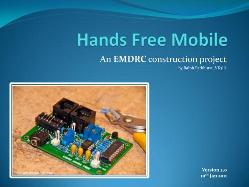
An EMDRC construction project<br />
by Ralph Parkhurst, VK3LL<br />
Prototype version PCB shown<br />
Version 2.0<br />
10 th Jan 2011
Why hands free<br />
• Safety – keep both hands on the<br />
steering wheel whilst operating your<br />
radio transceiver<br />
• Improved TX audio – the electret<br />
microphone is at a constant distance<br />
from the user’s mouth and tailored for<br />
optimum frequency response within<br />
your particular vehicle<br />
• No more curly cord – a tiny (8mm x<br />
15mm) microphone can be discreetly<br />
installed to provide a neat and tidy<br />
installation – XYL approved!
From humble<br />
beginnings...<br />
This is an updated design<br />
from an earlier construction<br />
project described in<br />
Amateur Radio Action<br />
magazine in the early ’90s<br />
and now features a PIC<br />
microcontroller, so it is now<br />
even easier to build.
Features<br />
• Adjustable microphone gain control<br />
• Adjustable bass and treble audio equalisation<br />
• All adjustments are made using 25-turn trim-pots for<br />
fine ‘tweaking’<br />
• 8 choices of on-board timeout duration (0.5min, 1min,<br />
2min, 2.5min, 3min, 4,min, 5min, 10min)<br />
• Two RJ45 connectors - one to the radio’s mic socket<br />
and the other for microphone loop-through<br />
• Momentary pushbutton PTT switch used to provide<br />
greatest versatility
Features (continued)<br />
• Flashing LED provides “on-air” indication<br />
• Visual indication 10 seconds before imminent timeout<br />
• Low cost of parts<br />
• Easy construction on a single, high quality PCB<br />
• All ‘thru-hole’ parts, no SMD soldering required<br />
• Uses a low cost electret microphone (supplied in the kit)<br />
• Complete kits readily available from EMDRC<br />
• No adjustments or mods inside your radio are required<br />
• Designed to work with just about every radio transceiver,<br />
using jumper pins on a 16-pin header...
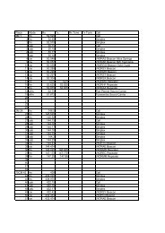
Header Jumpering: Examples for <strong>com</strong>mon radios*<br />
*IMPORTANT: Constructors are reminded<br />
that they must verify the strapping to suit<br />
their own specific radio transceiver.
Power connection<br />
• Many modern radios provide +8v or +9v at the mic connector – this will<br />
power the hands-free-board directly from the mic socket with a single<br />
cable to suit your radio (e.g. RJ45 to RJ45, or RJ45 to 8-pin round etc.).<br />
• Radios without +DC power at the mic socket can still be used - in these<br />
cases 13.8V is applied separately to the board’s “EXTERNAL POWER”<br />
connector (note that off-board 13.8v DC power filtering and suitable<br />
fusing is re<strong>com</strong>mended).<br />
• The PTT to the radio is an “open collector” output that is driven logic<br />
low (i.e. to ground) as required by most amateur transceivers. In the<br />
rare instance you need to invert the sense of the PTT line, you can<br />
solder a wire jumper on the PCB at position OPT1 which will invert the<br />
PTT line to the radio.
Schematic<br />
Low parts count for easy construction - just two ICs, one transistor, one<br />
regulator, and a handful of resistors and capacitors
Quality PCB provided in the kit<br />
Double sided, silkscreened with soldermask (50mm x 75mm)
Component Layout<br />
All parts mount on the double sided PCB using “through hole” <strong>com</strong>ponents<br />
for easy assembly*<br />
IMPORTANT: This<br />
resistor (R4) is marked<br />
on the silkscreen overlay<br />
of some Printed Circuit<br />
Boards as a 33k resistor.<br />
This is incorrect - it<br />
should be a 3k3 resistor,<br />
as shown here.<br />
*SKILL LEVEL: Constructors are advised that this is relatively densely populated board,<br />
so the skill required to solder this project should be considered “Intermediate Level”.
Parts List<br />
The following parts are supplied as part of the FULL EMDRC KIT:<br />
RESISTORS (all metal film, 2% or 5%)<br />
5 x 10k ¼ Watt (R1, R2, R14, R15, R16)<br />
4 x 3k3 ¼ Watt (R3, R4, R8, R11)<br />
1 x 4k7 ¼ Watt (R9)<br />
1 x 2k2 ¼ Watt (R7)<br />
1 x 6k8 ¼ Watt (R10)<br />
1 x 100R ¼ Watt (R12)<br />
1 x 470R ¼ Watt (R13)<br />
TRIMPOTS (all vertical multi-turn sealed)<br />
50k TRIMPOT 25-turn (GAIN)<br />
10K TRIMPOT 25-turn (LO)<br />
100K TRIMPOT 25-turn (HI)<br />
CAPACITORS<br />
1 x 1.0uF 50volt Multilayer Ceramic (C1)<br />
4 x 0.022uF 100volt Polyester Film (C2, C3, C4, C5)<br />
3 x 22uF 10volt Tantalum (C6, C7, C8)<br />
2 x 0.1uF 25volt Multilayer Ceramic (C9, C10)<br />
2 x 470pF 50volt Multilayer Ceramic (C11, C12)<br />
SEMICONDUCTORS and ICs<br />
1 x TL072 Dual OpAmp 8pin PDIP (IC1)<br />
1 x PIC18F1220-I/P pre-programmed MCU 18pin PDIP (IC2)<br />
1 x 1N5819 Schottky Diode (D1)<br />
1 x 1N4148 Diode (D2)<br />
1 x LM78L05 5volt Regulator (IC5)<br />
1 x BC548 NPN Transistor (Q2)<br />
1 x 5mm BLUE LED with mounting clip (“ON AIR”)<br />
OTHER<br />
3 x IC Sockets (one each of 8pin, 16pin, 18pin)<br />
2 x RJ45 PCB Sockets side entry (8/8pin)<br />
2 x 2-pin polarised headers (PTT and EXT POWER)<br />
2 x 2-Pin polarised plugs and pins<br />
1 x ‘SERPAC’ plastic case, model 131-BLACK<br />
1 x Electret Microphone and cable with 3.5mm stereo plug<br />
1 x Pushbutton Switch, momentary contact (PTT)<br />
1 x 3.5mm Stereo PCB socket (MIC INPUT)<br />
1 x 16pin IDC DIP plug (JUMPER)<br />
1 x 6-hole ferrite bead RF Choke (RFC)<br />
1 x PCB coded "EMDRC HANDS FREE“<br />
YOU WILL NEED TO PROVIDE: Solder, short lengths of hookup wire, a suitable cable from the <strong>Hands</strong>-<strong>Free</strong> Adapter to your radio, and<br />
optionally any additional cabling if you’d like your radio’s existing microphone to be connected to the ‘loop-through’ microphone socket.
Construction<br />
Assembly and Testing:<br />
ASSEMBLY<br />
1. Insert and solder all resistors, capacitors and diodes. Note carefully the polarity of the three 22uF Tantalum capacitors<br />
(C6, C7, C8) and the polarity of the two diodes (D1 and D2). On some PCBs, R4 is shown on the PCB overlay as 33k. This<br />
is incorrect, it should be 3k3 as per the schematic and parts list.<br />
2. Insert and solder the three IC sockets used by the PIC processor (18pin), the OpAmp (8pin) and the Jumper (16pin).<br />
3. Insert and solder the LED, the LM7805 voltage regulator and the BC548 transistor, taking care to orient the “flat” edge<br />
of these parts as per the silkscreened <strong>com</strong>ponent overlay on the PCB. Leave the LED lead length as long as possible to<br />
allow it to be aligned into a hole in the case later –a piece of spaghetti insulation over one lead is a wise idea to keep<br />
them from shorting out.<br />
4. Insert the RJ45 connectors by snapping them into the PCB, then solder.<br />
5. Insert the 3.5mm mic socket ensuring that it is properly seated on the PCB, then solder.<br />
6. Insert the TL072 and the PIC18F1220 into their respective sockets, noting carefully the orientation of these to<br />
<strong>com</strong>ponents to ensure they are aligned correctly as per the <strong>com</strong>ponent overlay (there is a tiny white dot identifying pin<br />
1 on the PCB).<br />
7. Do not solder anything to the OPT2 pins – this has a special purpose (discussed later).<br />
TESTING<br />
1. Wire and connect the PTT switch to the header on the PCB.<br />
2. Wire and connect to the Microphone socket on your radio (user supplied cabling – refer to separate EMDRC document<br />
titled “Jumper Diagram v2.<strong>pdf</strong>” for further assistance. DO NOT INSERT YOUR CUSTOM WIRED HEADER PLUG YET!<br />
3. Plug into the radio and turn on. Confirm that the expected DC voltage appears on the relevant pins of the 16pin<br />
JUMPER socket – this step is important as you do not want to short your +8v or +9v to ground as doing so may ‘fry’ the<br />
radio’s internal voltage regulator!<br />
4. Insert the 16pin Jumper (wired for your radio) and assemble into the case.
Construction (continued)<br />
Alignment and Use:<br />
ALIGNMENT<br />
1. Initially, rotate all trimpots anticlockwise for at least 25 turns - this will ensure that they are all at their minimum value.<br />
2. Now, wind the GAIN trimpot clockwise by 4 turns.<br />
3. Next. wind the LO trimpot clockwise by 12½ turns – this is half way or ‘centre’ for the 25-turn trimpot.<br />
4. Wind the HI trimpot clockwise by 12½ turns – this is half way or ‘centre’ for the 25-turn trimpot.<br />
5. This will get the hands free adapter set to the point where you can try it on-air or into a dummy load and make finer<br />
adjustments. Rotating the GAIN pot clockwise will increase the audio level. The LO and HI tripots are just like the Bass<br />
and Treble controls on a HiFi amplifier, that is clockwise rotation from centre will BOOST the HIghs or the LOws, whilst<br />
anticlockwise rotation from the centre with CUT the HIghs and LOws.<br />
6. Adjusting the HI and LO equalisation trimpots will effect the overall gain, so you will find a degree of interaction is<br />
needed with the GAIN trimpot to <strong>com</strong>pensate. Up to 12dB BOOST and CUT is provided by the two equalisation<br />
trimpots.<br />
USE IN THE VEHICLE<br />
1. Proper adjustment of the GAIN control is vital and don’t be surprised if it takes you several attempts to get it just right.<br />
There is a fine line between effective microphone placement, GAIN trimpot setting and background road noise<br />
transmitted, and you need to find the best balance between all three and what works for you.<br />
2. With care you should be able to achieve great results with only a minimal increase in road noise – please note that<br />
depending on how far your microphone is placed from your mouth and how “loud” your vehicle is, some increased<br />
degree of background road noise is inevitable – the trick is to make these adjustments carefully to prevent background<br />
road noise from be<strong>com</strong>ing objectionable. Adjust the gain control carefully – even a ½ turn can make a lot of difference!<br />
3. To assist further, a video is being produced which demonstrates how this hands-free mobile kit should sound when<br />
setup correctly.
LET’S GET MOBILE!<br />
To transmit using the <strong>Hands</strong> <strong>Free</strong> Adapter, just briefly press the PTT button (the one on the hands free adapter, not on your<br />
microphone!) The LED will begin flashing to warn you are now “ON THE AIR” and your radio will <strong>com</strong>mence transmitting.<br />
Initially your hands free adapter will have a timeout period set for 2½ minutes – this means that after 2.5 minutes of<br />
continuous transmission, the PTT line to the Tx will be disabled. Ten seconds before this timeout is invoked, the LED will<br />
begin to flash at very fast rate giving you a visual cue that timeout is imminent.<br />
If you’d like to change this timeout period, proceed as follows:<br />
a) Turn your radio off (which also turns the <strong>Hands</strong> <strong>Free</strong> Adapter off)<br />
b) Whilst holding down the PTT button (again, the one on the hands free adapter, not on your microphone) power on the<br />
radio – this enters a configuration mode where you can adjust the timeout value. You can now release the PTT.<br />
c) Each time you now briefly press the PTT button, the LED will flash a number of times to indicate the timeout setting:<br />
1 flash = 30 seconds<br />
2 flashes = 1 minute<br />
3 flashes = 2 minutes<br />
4 flashes = 2.5 minutes (default)<br />
5 flashes = 3 minutes<br />
6 flashes = 4 minutes<br />
7 flashes = 5 minutes<br />
8 flashes = 10 minutes<br />
(after this, the configuration program rolls over, starting from 1 flash again)<br />
d) After you count the number of flashes appropriate to the timeout period you desire, turn off the radio (and the <strong>Hands</strong><br />
<strong>Free</strong> Adapter), pause, and turn it back on again. The new timeout value is now stored permanently.<br />
e) If for some reason you don’t wish to use the timeout at all, it can be disabled by soldering a wire jumper on the PCB in<br />
position OPT2, but only do this if you have a genuinely valid reason for doing so!
FAQ<br />
Q. Are there any circumstances where the <strong>Hands</strong> <strong>Free</strong> Adapter should not be used<br />
A. In my opinion yes, there are two; if you have a very noisy vehicle (truck etc.) or you like to drive with the window<br />
down, you are probably better to use the regular microphone rather than hands free - unless you can position the<br />
microphone reasonably close to your mouth.<br />
Q. Can the <strong>Hands</strong> <strong>Free</strong> Adapter be used on HF/SSB<br />
A. Yes, it has been used with radios like the IC7000 (at 100 watts) and it works exceptionally well. You are re<strong>com</strong>mended<br />
not to use high levels of audio <strong>com</strong>pression when driving hands free - at high roads speeds, excessive road noise can<br />
lead to a resultant loss of intelligibility at the receiving end if the audio processing (<strong>com</strong>pression) within the radio is set<br />
higher than about 15%.<br />
Q. Can the <strong>Hands</strong> <strong>Free</strong> Adapter be used with DSTAR<br />
A. Yes, it has been used with radios like the ID800 and it works perfectly. Very <strong>com</strong>plimentary audio reports have been<br />
received.<br />
Q. What is considered the best placement for the electret microphone<br />
A. As close as possible to your mouth – typically within 30cm – for example mounted above the drivers door, on the sun<br />
visor, in the roof headlining – anywhere that gets the microphone as close to your mouth as possible.<br />
Q. My FM radio’s transmit audio is too soft – will this kit improve it<br />
A. Possibly. In principle, it’s best to get your radio set up correctly first with the standard microphone – making sure that<br />
radio’s FM deviation and mic gain are correctly adjusted first (this kit will NOT correct an under deviating FM signal –<br />
that MUST be set within the radio). However you will have much wider control over microphone gain and hence how<br />
“loud” your signal sounds on a correctly set FM rig. Further, you’ll be able to <strong>com</strong>pensate for the often poor sounding<br />
audio that some of the ‘standard’ supplied mics exhibit these days. For example, users of the IC7000 will be delighted<br />
with the improved top end crispness and tailored low frequency rolloff that can be achieved with this kit after it is<br />
properly setup.