flow controls
flow controls
flow controls

Create successful ePaper yourself
Turn your PDF publications into a flip-book with our unique Google optimized e-Paper software.
D<br />
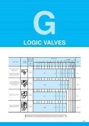
FLOW CONTROLS<br />
Valve Type<br />
Graphic<br />
Symbols<br />
Maximum<br />
Operating<br />
Pressure<br />
MPa<br />
(PSI)<br />
1<br />
2<br />
3<br />
Maximum Flow<br />
U.S.GPM<br />
1 5 10 50 100 500 1000<br />
5<br />
10<br />
20 30<br />
50<br />
100<br />
200 300<br />
500<br />
1000 2000 3000 5000<br />
L/min<br />
Page<br />
Flow Control Valves<br />
21<br />
(3050)<br />
FG<br />
01 02 03 06<br />
10<br />
277<br />
Flow Control and<br />
Check Valves<br />
21<br />
(3050)<br />
FCG 01<br />
02<br />
03<br />
06<br />
10<br />
277<br />
Pilot Operated<br />
Flow Control Valves<br />
21<br />
(3050)<br />
FHG<br />
02<br />
03<br />
06<br />
10<br />
289<br />
Pilot Operated<br />
Flow Control and<br />
Check Valves<br />
21<br />
(3050)<br />
FHCG 02<br />
03<br />
06<br />
10<br />
289<br />
Restrictors<br />
25<br />
(3630)<br />
SRT/SRG<br />
03<br />
06<br />
10<br />
SRF-<br />
16<br />
(Rated Flow)<br />
299<br />
One Way Restrictors<br />
25<br />
(3630)<br />
SRCT/SRCG<br />
03<br />
06<br />
10<br />
SRCF-<br />
16<br />
(Rated Flow)<br />
299<br />
Throttle Modules<br />
<br />
25<br />
(3630)<br />
TC1G<br />
01<br />
03<br />
305<br />
Throttle & Check<br />
Modules<br />
<br />
25<br />
(3630)<br />
TC2G<br />
01<br />
03<br />
305<br />
Deceleration Valves<br />
21<br />
(3050)<br />
ZT/ZG<br />
03<br />
06 10<br />
310<br />
Deceleration &<br />
Check Valves<br />
21<br />
(3050)<br />
ZCT/ZCG<br />
03<br />
06 10<br />
310<br />
Feed Control Valves<br />
<br />
<br />
14<br />
(2030)<br />
UCF1G/UCF2G<br />
01<br />
03<br />
04<br />
318<br />
Needle Valves<br />
35<br />
(5080)<br />
GCT/<br />
GCTR<br />
02<br />
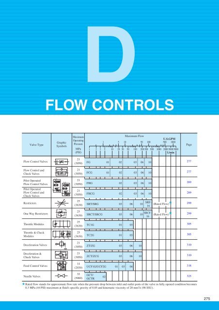
Rated <strong>flow</strong> stands for approximate <strong>flow</strong> rate when the pressure drop between inlet and outlet ports of the valve in fully opened condition becomes<br />
0.3 MPa (44 PSI) maximum at fluid's specific gravity of 0.85 and kinematic viscosity of 20 mm 2 /s (98 SSU).<br />
325<br />
275
Hydraulic Fluids<br />
Fluid Types<br />
Any type of hydraulic fluids listed in the table below can be used.<br />
Petroleum base oils<br />
Synthetic fluids<br />
Water containing fluids<br />
Use fluids equivalent to ISO VG 32 or VG 46.<br />
Use phosphate ester or polyol ester fluid. When phosphate ester fluid is used, prefix "F-" to<br />
the model number because the special seals (fluororubber) are required to be used.<br />
Use water-glycol fluid.<br />
Note: For use with hydraulic fluids other than those listed above, please consult your Yuken representatives in advance.<br />
Recommended Viscosity and Oil Temperatures<br />
Use hydraulic fluids which satisfy the recommended viscosity and oil temperatures given below.<br />
Name<br />
Viscosity<br />
Temperature<br />
Flow Control Valves<br />
Flow Control and Check Valves<br />
Pilot Operated Flow Control Valves<br />
Pilot Operated Flow Control and Check Valves<br />
Feed Control Valves<br />
Restrictors<br />
One Way Restrictors<br />
Throttle Modules<br />
Throttle and Check Modules<br />
Deceleration Valves<br />
Deceleration and Check Valves<br />
Needle Valves<br />
20 - 200 mm 2 /s<br />
(98 - 900 SSU)<br />
15 - 400 mm 2 /s<br />
(77 - 1800 SSU)<br />
-15 - +70°C<br />
(5 - 158°F)<br />
Control of Contamination<br />
Due caution must be paid to maintaining control over contamination of the hydraulic fluids which may otherwise lead to<br />
breakdowns and shorten the life of the valves. Please maintain the degree of contamination within NAS 1638-Grade 12.<br />
Use 25 µm or finer line filter.<br />
276<br />
Flow Controls
FLOW CONTROLS<br />
Flow Control Valves / Flow Control and Check Valves<br />
These valves are pressure and temperature compensating type valves and<br />
maintain a constant <strong>flow</strong> rate independent of change in system pressure<br />
(load) and temperature (viscosity of the fluid). They control <strong>flow</strong> rate of the<br />
hydraulic circuit and eventually control speed of the actuator precisely.<br />
Valves with an integral check valve allow a controlled <strong>flow</strong> and reverse free<br />
<strong>flow</strong>. Repeated resetting can be made easily with a digital readout.<br />
Specifications<br />
Model Numbers<br />
FG<br />
FCG -01- 4<br />
8<br />
- * -11 *<br />
FG<br />
FCG<br />
FG<br />
FCG<br />
FG<br />
FCG<br />
FG<br />
FCG<br />
-02-30- * -30 *<br />
-03-125- * -30 *<br />
-06-250- * -30 *<br />
-10-500- * -30 *<br />
Model Number Designation<br />
FC<br />
Series Number<br />
F:<br />
Flow Control<br />
Valves<br />
FC:<br />
Flow Control and<br />
Check Valves<br />
Max. Metred<br />
Flow Capacity<br />
L/min (U.S.GPM)<br />
4(1.06)<br />
8(2.1)<br />
30(7.9)<br />
125(33)<br />
250(66)<br />
500(132)<br />
G -01 -8<br />
-N -11<br />
Type of<br />
Mounting<br />
G:<br />
Sub-plate<br />
Mounting<br />
Min. Metred<br />
Flow Capacity<br />
L/min (U.S.GPM)<br />
0.02(.005)<br />
{0.04 (.011)}<br />
0.05 (.013)<br />
0.2 (.053)<br />
2 (.53)<br />
4 (1.06)<br />
The figures in the brace are for pressures above 7 MPa (1020 PSI).<br />
F-<br />
Special Seals<br />
F:<br />
Special Seals<br />
for Phosphate<br />
Ester Type<br />
Fluids<br />
(Omit if not<br />
required)<br />
Valve<br />
Size<br />
01<br />
02<br />
03<br />
06<br />
10<br />
Max.<br />
Operating Pressure<br />
MPa (PSI)<br />
14 (2030 )<br />
21 (3050)<br />
Max. Metred Flow Capacity<br />
L/min (U.S.GPM)<br />
4 : 4 (1.06)<br />
8 : 8 (2.1)<br />
30 : 30 (7.9)<br />
125 : 125 (33)<br />
250 : 250 (66)<br />
500 : 500 (132)<br />
Design Standards: None...........Japanese Standard "JIS" and European Design Standard<br />
90................N. American Design Standard<br />
Approx. Mass<br />
kg (lbs.)<br />
1.3 (2.9)<br />
3.8 (8.4)<br />
7.9 (17.4)<br />
23 (50.7)<br />
52 (115)<br />
Pres. Compensator<br />
Stroke Adjustment<br />
N:<br />
Applicable only for<br />
Pres. Compensator<br />
Stroke Adjustment<br />
(Option - Omit if<br />
not required)<br />
Design<br />
Number<br />
11<br />
30<br />
30<br />
30<br />
30<br />
*<br />
Design<br />
Standards<br />
Refer to<br />
D<br />
Flow Control Valves<br />
Flow Control and Check Valves<br />
Attachment<br />
Mounting Bolts<br />
Valve Model<br />
Numbers<br />
FG/FCG-01<br />
Japanese Std. "JIS" &<br />
European Design Std.<br />
M5<br />
55 Lg.<br />
Socket Head Cap Screw<br />
N. American Design Std.<br />
No.10-24 UNC<br />
2-1/4 Lg.<br />
Qty.<br />
4<br />
Graphic Symbols<br />
FG<br />
FG/FCG-02<br />
M8<br />
50 Lg.<br />
5/16-18 UNC 2 Lg.<br />
4<br />
FG/FCG-03<br />
M10<br />
75 Lg.<br />
3/8-16 UNC 3 Lg.<br />
4<br />
FG/FCG-06<br />
M16<br />
130 Lg.<br />
5/8-11 UNC 5 Lg.<br />
4<br />
FG/FCG-10<br />
M20<br />
160 Lg.<br />
3/4-10 UNC 6-1/2 Lg.<br />
4<br />
FCG<br />
Option<br />
Pres. compensator stroke adjustment<br />
Can reduce jumping at the start of the actuator.<br />
Flow Control Valves / Flow Control and Check Valves<br />
277
Sub-plate<br />
Valve<br />
Model<br />
Numbers<br />
FG<br />
FCG<br />
-01<br />
FG<br />
FCG<br />
-02<br />
FG<br />
FCG<br />
-03<br />
FG<br />
FCG<br />
-06<br />
FG<br />
FCG<br />
-10<br />
Japanese Standard "JIS"<br />
Sub-plate<br />
Model No.<br />
FGM-01X-10<br />
FGM-02-20<br />
FGM-02X-20<br />
FGM-02Y-20<br />
FGM-03-20<br />
FGM-03X-20<br />
FGM-03Y-20<br />
FGM-03Z-20<br />
FGM-06X-20<br />
FGM-06Y-20<br />
FGM-06Z-20<br />
FGM-10Y-20<br />
Thread<br />
Size<br />
Rc 1/4<br />
Rc 1/4<br />
Rc 3/8<br />
Rc 1/2<br />
Rc 3/8<br />
Rc 1/2<br />
Rc 3/4<br />
Rc 1<br />
Rc 1<br />
Rc 1-1/4<br />
Rc 1-1/2<br />
1-1/2, 2<br />
European Design Std.<br />
Sub-plate<br />
Model No.<br />
FGM-01X-1080<br />
FGM-02-2080<br />
FGM-02X-2080<br />
FGM-02Y-2080<br />
FGM-03-2080<br />
FGM-03X-2080<br />
FGM-03Y-2080<br />
FGM-03Z-2080<br />
FGM-06X-2080<br />
FGM-06Y-2080<br />
FGM-06Z-2080<br />
FGM-10Y-20<br />
Thread<br />
Size<br />
1/4 BSP.F<br />
1/4 BSP.F<br />
3/8 BSP.F<br />
1/2 BSP.F<br />
3/8 BSP.F<br />
1/2 BSP.F<br />
3/4 BSP.F<br />
1 BSP.F<br />
1 BSP.F<br />
1-1/4 BSP.F<br />
1-1/2 BSP.F<br />
1-1/2, 2<br />
N. American Design Std. Approx.<br />
Sub-plate Thread<br />
Mass<br />
Model No. Size kg (lbs.)<br />
FGM-01X-1090<br />
FGM-02-2090<br />
FGM-02X-2090<br />
FGM-02Y-2090<br />
FGM-03-2090<br />
FGM-03X-2090<br />
FGM-03Y-2090<br />
FGM-03Z-2090<br />
FGM-06X-2090<br />
FGM-06Y-2090<br />
FGM-06Z-2090<br />
FGM-10Y-2090<br />
1/4 NPT<br />
1/4 NPT<br />
3/8 NPT<br />
1/2 NPT<br />
3/8 NPT<br />
1/2 NPT<br />
3/4 NPT<br />
1 NPT<br />
1 NPT<br />
1-1/4 NPT<br />
1-1/2 NPT<br />
1-1/2, 2<br />
0.8 (1.8)<br />
2.3 (5.1)<br />
2.3 (5.1)<br />
3.1 (6.8)<br />
3.9 (8.6)<br />
3.9 (8.6)<br />
5.7 (12.6)<br />
5.7 (12.6)<br />
12.5 (27.6)<br />
16 (35.3)<br />
16 (35.3)<br />
37 (81.6)<br />
Sub-plates are available. Specify the sub-plate model number from<br />
the table above. When sub-plates are not used, the mounting surface<br />
should have a good machined finish.<br />
FGM-10Y is special type sub-plate to be used with pipe flange. When<br />
ordering FGM-10Y, specify pipe flange kit in addition to FGM-10Y<br />
referring to F3 pipe flanges show on page 821.<br />
Instructions<br />
Min. required pressure difference<br />
The minimum differential pressure between inlet and outlet port is required to obtain the optimum pressure<br />
compensation. It varies according to the <strong>flow</strong> rate to be set. For details, please refer to the performance curves.<br />
Free <strong>flow</strong><br />
Check valve pressure drops vary with <strong>flow</strong> rates. If models with check valves are used, see free <strong>flow</strong> pressure drop<br />
characteristics.<br />
Flow adjustment<br />
[F * G-01]<br />
Loosen the locking screw and turn the <strong>flow</strong> adjustment dial clockwise for increase, and anti-clockwise for decrease. The<br />
dial makes about 4 revolutions from zero to full <strong>flow</strong> and the valve opening is indicated on the revolution indicator.<br />
(Refer to characteristics of "Metred Flow vs. Dial Position").<br />
After <strong>flow</strong> adjustments, tighten the locking screw.<br />
[F * G-02, 03, 06, 10]<br />
Loosen the locking screw and turn the <strong>flow</strong> adjustment handle clockwise for increase, and anti-clockwise for decrease.<br />
Open condition is indicated in digital-scale in built-in revolution indicator (Refer to the characteristics of "Metred Flow<br />
vs. Dial Position").<br />
After <strong>flow</strong> adjustments, tighten the locking screw.<br />
Line filter<br />
To carry out <strong>flow</strong> adjustments by as small degree as 2 L/min (.53 U.S.GPM) or less, be sure to use a line filter of 10 µm<br />
or finer and install it near the valve inlet.<br />
278<br />
Flow Control Valves / Flow Control and Check Valves
FLOW CONTROLS<br />
FG/FCG-01-* - * -11/1190<br />
Revolution Indicator<br />
4 3<br />
2<br />
2 1 0 9 8<br />
Locking Screw<br />
2.5(.10) Hex. Soc.<br />
Tightening Torque:<br />
0.25 - 0.3 Nm<br />
(2.2 - 2.7 IN. lbs.)<br />
5.5(.22) Dia. Through<br />
9(.35) Dia. Spotface<br />
4 Places<br />
7.5<br />
(.30)<br />
Controlled Flow<br />
Outlet or<br />
Reversed Free Flow<br />
Inlet Port<br />
INC.<br />
Flow Adjustment Dial<br />
22.5<br />
(.89)<br />
Dia.<br />
Fully Extended<br />
81.5(3.21)<br />
66<br />
(2.60)<br />
51<br />
(2.01)<br />
25.5<br />
(1.00)<br />
FG/FCG-02-30-* -30/3090<br />
FG/FCG-03-125-* -30/3090<br />
Pressure Compensator<br />
Stroke Adjustment<br />
(Only for FG<br />
FCG<br />
-01- -N )<br />
13(.51)<br />
Dia.<br />
16.5<br />
(.65)<br />
31<br />
(1.22)<br />
43<br />
(1.69)<br />
58<br />
(2.28)<br />
Controlled Flow Inlet or<br />
Reversed Free Flow Outlet Port<br />
7.5<br />
(.30)<br />
3(.12)<br />
5.5(.22)<br />
Dia.<br />
1<br />
8 7 6<br />
DIMENSIONS IN<br />
MILLIMETRES (INCHES)<br />
Fully Extended<br />
84(3.31)<br />
53.5<br />
(2.11)<br />
45<br />
(1.77)<br />
44<br />
(1.73)<br />
17<br />
(.67)<br />
5<br />
(.20)<br />
Locating Pin<br />
4(.16) Dia.<br />
Mounting Surface<br />
(O-Rings Furnished)<br />
Mounting surface:<br />
F G-02: ISO 6263-AB-06-4-B<br />
F G-03: ISO 6263-AK-07-2-A<br />
D<br />
Flow Control Valves<br />
Flow Control and Check Valves<br />
Locking Screw<br />
2(.08) Hex. Soc.<br />
H<br />
46<br />
(1.81) Dia.<br />
Fully Extended "C"<br />
D<br />
E<br />
F<br />
Controlled Flow Inlet or<br />
Reversed Free Flow Outlet Port<br />
Pressure Compensator<br />
Stroke Adjustment<br />
(Only for FG<br />
FCG - - -N )<br />
Q<br />
S<br />
T<br />
X<br />
U<br />
"V" Dia. Through<br />
"W" Dia. Spotface<br />
4 Places<br />
Revolution Indicator<br />
234<br />
14(.55)<br />
Dia.<br />
N<br />
L<br />
K P<br />
J<br />
6<br />
(.24)<br />
Locating Pin<br />
6(.24) Dia.<br />
"Y" Places<br />
Controlled Flow Outlet or<br />
Reversed Free Flow Inlet Port<br />
Model<br />
No.<br />
C<br />
FG<br />
FCG -02 116<br />
(4.57)<br />
FG<br />
FCG -03 145<br />
(5.71)<br />
D<br />
96<br />
(3.78)<br />
125<br />
(4.92)<br />
E<br />
76.2<br />
(3.00)<br />
101.6<br />
(4.00)<br />
F<br />
38.1<br />
(1.50)<br />
50.8<br />
(2.00)<br />
H<br />
9.9<br />
(.39)<br />
11.7<br />
(.46)<br />
Flow Adjustment Handle<br />
J<br />
104.5<br />
(4.11)<br />
125<br />
(4.92)<br />
K<br />
82.6<br />
(3.25)<br />
101.6<br />
(4.00)<br />
INC.<br />
Dimensions mm (Inches)<br />
L<br />
44.3<br />
(1.74)<br />
61.8<br />
(2.43)<br />
N<br />
24<br />
(.94)<br />
29.8<br />
(1.17)<br />
P<br />
9.9<br />
(.39)<br />
11.7<br />
(.46)<br />
Q<br />
123<br />
(4.84)<br />
152<br />
(5.98)<br />
S<br />
69<br />
(2.72)<br />
98<br />
(3.86)<br />
T<br />
40<br />
(1.57)<br />
64<br />
(2.52)<br />
U<br />
23<br />
(.91)<br />
41<br />
(1.61)<br />
V<br />
8.8<br />
(.35)<br />
11<br />
(.43)<br />
Mounting Surface<br />
(O-Rings Furnished)<br />
W<br />
14<br />
(.55)<br />
17.5<br />
(.69)<br />
X<br />
39<br />
(1.54)<br />
63<br />
(2.48)<br />
Y<br />
1<br />
2<br />
Flow Control Valves / Flow Control and Check Valves<br />
279
FG/FCG-06-250-* -30/3090<br />
FG/FCG-10-500-* -30/3090<br />
Mounting surface:<br />
F G-06: ISO 6263-AP-08-2-A<br />
DIMENSIONS IN<br />
MILLIMETRES (INCHES)<br />
Locking Screw<br />
2(.08) Hex. Soc.<br />
"X" Dia. Through<br />
"Y" Dia. Spotface<br />
4 Places<br />
Flow Adjustment Handle<br />
H<br />
46<br />
(1.81)<br />
Dia.<br />
Fully Extended "C"<br />
D<br />
E<br />
F<br />
N<br />
P<br />
Controlled Flow Inlet or<br />
Reversed Free Flow Outlet Port<br />
Pressure Compensator<br />
Stroke Adjustment<br />
(Only for FG<br />
FCG - - -N )<br />
S<br />
T<br />
a<br />
U<br />
W<br />
INC.<br />
Locating Pin<br />
"V" Dia.<br />
2 Places<br />
Controlled Flow Outlet or<br />
Reversed Free Flow Inlet Port<br />
Z<br />
Revolution Indicator<br />
L<br />
Q<br />
121<br />
K<br />
J<br />
Only for Flow Control and Check Valves<br />
( FCG- - -N)<br />
Mounting Surface<br />
(O-Rings Furnished)<br />
Model<br />
No.<br />
C<br />
FG<br />
FCG -06 198<br />
(7.80)<br />
FG<br />
FCG -10 267<br />
(10.51)<br />
D<br />
180<br />
(7.09)<br />
244<br />
(9.61)<br />
E<br />
146.1<br />
(5.75)<br />
196.9<br />
(7.75)<br />
F<br />
73<br />
(2.87)<br />
98.5<br />
(3.88)<br />
H<br />
17<br />
(.67)<br />
23.5<br />
(.93)<br />
J<br />
174<br />
(6.85)<br />
228<br />
(8.98)<br />
K<br />
133.4<br />
(5.25)<br />
177.8<br />
(7.00)<br />
L<br />
99<br />
(3.90)<br />
144.5<br />
(5.69)<br />
Dimensions mm (Inches)<br />
N<br />
44<br />
(1.73)<br />
61<br />
(2.40)<br />
P<br />
20.3<br />
(.80)<br />
25<br />
(.98)<br />
Q<br />
184<br />
(7.24)<br />
214<br />
(8.43)<br />
S<br />
130<br />
(5.12)<br />
160<br />
(6.30)<br />
T<br />
105<br />
(4.13)<br />
137<br />
(5.39)<br />
U<br />
65<br />
(2.56)<br />
85<br />
(3.35)<br />
V<br />
16<br />
(.63)<br />
18<br />
(.71)<br />
W<br />
7<br />
(.28)<br />
10<br />
(.39)<br />
X<br />
17.5<br />
(.69)<br />
21.5<br />
(.85)<br />
Y<br />
26<br />
(1.02)<br />
32<br />
(1.26)<br />
Z<br />
10<br />
(.39)<br />
7.5<br />
(.30)<br />
a<br />
103<br />
(4.06)<br />
135<br />
(5.31)<br />
280<br />
Flow Control Valves / Flow Control and Check Valves
FLOW CONTROLS<br />
FGM-01X-10/1080/1090<br />
5.5(.22) Dia. Through<br />
9(.35) Dia. Spotface<br />
4 Places<br />
18.5<br />
(.73)<br />
51<br />
(2.01)<br />
36<br />
(1.42)<br />
9<br />
(.35)<br />
"A" Thd. (From Rear)<br />
2 Places<br />
"B" Thd. "C" Deep<br />
4 Places<br />
5(.20) Dia. 8(.31) Deep<br />
6<br />
(.24)<br />
22<br />
(.87)<br />
17<br />
(.67)<br />
16<br />
(.63)<br />
16.5<br />
(.65)<br />
34.5<br />
(1.36)<br />
D<br />
43<br />
(1.69)<br />
14<br />
(.55)<br />
55<br />
(2.17)<br />
D<br />
12.5<br />
(.49)<br />
6<br />
(.24)<br />
63<br />
(2.48)<br />
76<br />
(2.99)<br />
88<br />
(3.46)<br />
6(.24) Dia.<br />
2 Places<br />
FGM-02* -20/2080/2090<br />
Sub-plate<br />
Model Numbers<br />
FGM-01X-10<br />
FGM-01X-1080<br />
FGM-01X-1090<br />
8.8(.35) Dia. Through<br />
14(.55) Dia. Spotface<br />
4 Places<br />
23.8<br />
(.94)<br />
11.5<br />
(.45)<br />
"A" Thd.<br />
Rc 1/4<br />
1/4 BSP.F<br />
1/4 NPT<br />
31.9<br />
(1.26)<br />
79.4<br />
(3.13)<br />
76.2<br />
(3.00)<br />
54<br />
(2.13)<br />
E<br />
9.5<br />
(.37)<br />
"B" Thd. C D<br />
M5<br />
M5<br />
No.10-24 UNC<br />
14 (.55)<br />
14 (.55)<br />
15 (.59)<br />
14<br />
(.55)<br />
34.5 (1.36)<br />
30.0 (1.18)<br />
34.5 (1.36)<br />
"D" Dia. 2 Places<br />
"B" Thd. "C" Deep<br />
4 Places<br />
7(.28) Dia. 10(.39) Deep<br />
DIMENSIONS IN<br />
MILLIMETRES (INCHES)<br />
H<br />
16<br />
(.63)<br />
15<br />
(.59)<br />
Flow Control Valves<br />
Flow Control and Check Valves<br />
82.6<br />
(3.25)<br />
52.4<br />
(2.06)<br />
F<br />
11.1<br />
(.44)<br />
78<br />
(3.07)<br />
106<br />
(4.17)<br />
22<br />
(.87)<br />
10<br />
(.39)<br />
96<br />
(3.78)<br />
120<br />
(4.72)<br />
140<br />
(5.51)<br />
"A" Thd. (From Rear)<br />
2 Places<br />
Sub-plate<br />
Model Numbers<br />
"A" Thd.<br />
"B" Thd. C D<br />
E F H<br />
FGM-02-20<br />
FGM-02-2080<br />
FGM-02-2090<br />
FGM-02X-20<br />
FGM-02X-2080<br />
FGM-02X-2090<br />
FGM-02Y-20<br />
FGM-02Y-2080<br />
FGM-02Y-2090<br />
Rc 1/4<br />
1/4 BSP.F<br />
1/4 NPT<br />
Rc 3/8<br />
3/8 BSP.F<br />
3/8 NPT<br />
Rc 1/2<br />
1/2 BSP.F<br />
1/2 NPT<br />
M8<br />
5/16-18 UNC<br />
M8<br />
5/16-18 UNC<br />
M8<br />
5/16-18 UNC<br />
14 (.55)<br />
18 (.71)<br />
14 (.55)<br />
18 (.71)<br />
14 (.55)<br />
18 (.71)<br />
11.0 (.43)<br />
11.7 (.46)<br />
11.0 (.43)<br />
14.0 (.55)<br />
15.2 (.60)<br />
14.0 (.55)<br />
14.0 (.55)<br />
15.0 (.59)<br />
14.0 (.55)<br />
54<br />
(2.13)<br />
51<br />
(2.01)<br />
11.1<br />
(.44)<br />
14<br />
(.55)<br />
25<br />
(.98)<br />
35<br />
(1.38)<br />
Flow Control Valves / Flow Control and Check Valves<br />
281
FGM-03* -20/2080/2090<br />
"A" Thd. (From Rear)<br />
2 Places<br />
33.2<br />
(1.31)<br />
0.8<br />
(.03)<br />
102.4(4.03)<br />
101.6(4.00)<br />
75(2.95)<br />
F<br />
E<br />
20.6<br />
(.81)<br />
14.2<br />
(.56)<br />
"D" Dia. 2 Places<br />
"B" Thd. "C" Deep<br />
4 Places<br />
20(.79) Dia. 15(.59) Deep 2 Places<br />
K<br />
20(.79)<br />
19(.75)<br />
86.5<br />
(3.41)<br />
J<br />
28.6<br />
(1.13)<br />
11.1<br />
(.44)<br />
101.6<br />
(4.00)<br />
130<br />
(5.12)<br />
H<br />
21.5(.85)<br />
11(.43)<br />
125(4.92)<br />
146(5.75)<br />
168(6.61)<br />
11(.43) Dia. Through<br />
17.5(.69) Dia. Spotface<br />
4 Places<br />
Sub-plate Model Numbers "A" Thd. "B" Thd. C D<br />
E F H<br />
J<br />
K<br />
FGM-03-20<br />
FGM-03-2080<br />
FGM-03-2090<br />
FGM-03X-20<br />
FGM-03X-2080<br />
FGM-03X-2090<br />
FGM-03Y-20<br />
FGM-03Y-2080<br />
FGM-03Y-2090<br />
FGM-03Z-20<br />
FGM-03Z-2080<br />
FGM-03Z-2090<br />
Rc 3/8<br />
3/8 BSP.F<br />
3/8 NPT<br />
Rc 1/2<br />
1/2 BSP.F<br />
1/2 NPT<br />
Rc 3/4<br />
3/4 BSP.F<br />
3/4 NPT<br />
Rc 1<br />
1 BSP.F<br />
1 NPT<br />
M10<br />
3/8-16 UNC<br />
M10<br />
3/8-16 UNC<br />
M10<br />
3/8-16 UNC<br />
M10<br />
3/8-16 UNC<br />
18 (.71)<br />
21 (.83)<br />
18 (.71)<br />
21 (.83)<br />
18 (.71)<br />
21 (.83)<br />
18 (.71)<br />
21 (.83)<br />
14.0 (.55)<br />
15.0 (.59)<br />
14.0 (.55)<br />
17.5 (.69)<br />
19.0 (.75)<br />
17.5 (.69)<br />
23.0 (.91)<br />
75<br />
(2.95)<br />
70<br />
(2.76)<br />
20.6<br />
(.81)<br />
25.6<br />
(1.01)<br />
11.1<br />
(.44)<br />
16.1<br />
(.63)<br />
86.5<br />
(3.41)<br />
81.5<br />
(3.21)<br />
25<br />
(.98)<br />
40<br />
(1.57)<br />
FGM-06* -20/2080/2090<br />
17.5(.69) Dia. Through<br />
26(1.02) Dia. Spotface<br />
4 Places<br />
20.3<br />
(.80)<br />
52<br />
(2.05)<br />
1.6<br />
(.06)<br />
146.1(5.75)<br />
144.4(5.69)<br />
104.8(4.13)<br />
E<br />
D<br />
22.2<br />
(.87)<br />
29(1.14) Dia.<br />
2 Places<br />
"B" Thd. "C" Deep<br />
4 Places<br />
17(.67) Dia. 10(.39) Deep<br />
2 Places<br />
24<br />
(.94)<br />
DIMENSIONS IN<br />
MILLIMETRES (INCHES)<br />
J<br />
K<br />
L<br />
133.4<br />
(5.25)<br />
104.8<br />
(4.13)<br />
F<br />
41.3<br />
(1.63)<br />
12.7<br />
(.50)<br />
126<br />
(4.96)<br />
174<br />
(6.85)<br />
H<br />
35(1.38)<br />
19(.75)<br />
180(7.09)<br />
212(8.35)<br />
250(9.84)<br />
"A" Thd. (From Rear)<br />
2 Places<br />
Sub-plate Model Numbers "A" Thd. "B" Thd. C D<br />
E F H<br />
J<br />
K<br />
L<br />
FGM-06X-20<br />
FGM-06X-2080<br />
FGM-06X-2090<br />
FGM-06Y-20<br />
FGM-06Y-2080<br />
FGM-06Y-2090<br />
FGM-06Z-20<br />
FGM-06Z-2080<br />
FGM-06Z-2090<br />
Rc 1<br />
1 BSP.F<br />
1 NPT<br />
Rc 1-1/4<br />
1-1/4 BSP.F<br />
1-1/4 NPT<br />
Rc 1-1/2<br />
1-1/2 BSP.F<br />
1-1/2 NPT<br />
M16<br />
5/8-11 UNC<br />
M16<br />
5/8-11 UNC<br />
M16<br />
5/8-11 UNC<br />
30 (1.18)<br />
35 (1.38)<br />
30 (1.18)<br />
35 (1.38)<br />
30 (1.18)<br />
35 (1.38)<br />
104.8<br />
(4.13)<br />
99<br />
(3.90)<br />
22.2<br />
(.87)<br />
34<br />
(1.34)<br />
104.8<br />
(4.13)<br />
99<br />
(3.90)<br />
18<br />
(.71)<br />
23<br />
(.91)<br />
45<br />
(1.77)<br />
60<br />
(2.36)<br />
35<br />
(1.38)<br />
40<br />
(1.57)<br />
34<br />
(1.34)<br />
39<br />
(1.54)<br />
282<br />
Flow Control Valves / Flow Control and Check Valves
FLOW CONTROLS<br />
FGM-10Y-20/2090<br />
"A" Thd. 32(1.26) Deep<br />
4 Places<br />
177.8<br />
(7.00)<br />
144.5<br />
(5.69)<br />
36<br />
(1.42)<br />
55. 5<br />
(2.19)<br />
29<br />
(1.14)<br />
17.3<br />
(.68)<br />
68.5<br />
(2.70)<br />
1.6<br />
(.06)<br />
198.4<br />
(7.81)<br />
196.9<br />
(7.75)<br />
144.5<br />
(5.69)<br />
140<br />
(5.51)<br />
34.9<br />
(1.37)<br />
73<br />
(2.87)<br />
73<br />
(2.87)<br />
11<br />
(.43)<br />
DIMENSIONS IN<br />
MILLIMETRES (INCHES)<br />
D<br />
73<br />
(2.87)<br />
228<br />
(8.98)<br />
43.5(1.71) Dia.<br />
2 Places<br />
"B" Thd. "C" Deep<br />
8 Places (From Rear)<br />
20(.79) Dia. 15(.59) Deep<br />
2 Places<br />
250<br />
(9.84)<br />
80<br />
(3.15)<br />
50<br />
(1.97)<br />
48<br />
(1.89)<br />
100<br />
(3.94) SQ.<br />
Pipe Flange<br />
21.5(.85) Dia. Through<br />
32(1.26) Dia. Spotface<br />
4 Places<br />
45<br />
(1.77)<br />
25<br />
(.98)<br />
73<br />
(2.87)<br />
244<br />
(9.61)<br />
284<br />
(11.18)<br />
334<br />
(13.15)<br />
Sub-plate<br />
Model Numbers<br />
FGM-10Y-20<br />
FGM-10Y-2090<br />
"A" Thd.<br />
M20<br />
3/4-10 UNC<br />
48(1.89) Dia.<br />
2 Places<br />
"B" Thd.<br />
M16<br />
5/8-11 UNC<br />
C<br />
32 (1.26)<br />
34 (1.34)<br />
Flow Control Valves<br />
Flow Control and Check Valves<br />
Flow Control Valves / Flow Control and Check Valves<br />
283
Metred Flow vs. Differential Pressure<br />
Flow Rate<br />
U.S.GPM L/min<br />
2.15 8.2<br />
2.10 8.0<br />
2.05 7.8<br />
1.10 4.2<br />
1.05 4.0<br />
1.00 3.8<br />
0.022<br />
.0055 0.020<br />
.0050 0.018<br />
0 2 4 6 8 10 12 14 MPa<br />
Metred Flow vs. Viscosity<br />
FG<br />
-01<br />
FG<br />
FCG FCG<br />
-01<br />
Flow Rate<br />
U.S.GPM L/min<br />
2.2 8.4<br />
2.1 8.0<br />
2.0 7.6<br />
1.10 4.2<br />
1.05 4.0<br />
1.00 3.8<br />
.0060 0.022<br />
.0055 0.020<br />
.0050 0.018<br />
0 20 40 60 80 100 120 140 160 mm 2 /s<br />
U.S.GPM L/min<br />
8.5 32<br />
8.0 30<br />
7.5 28<br />
2.15 8.2<br />
2.10 8.0<br />
2.05 7.8<br />
0.52<br />
.135<br />
.130 0.50<br />
0.48<br />
Flow Rate<br />
0 500 1000 1500 2000 PSI<br />
Differential Pressure<br />
FG<br />
FCG<br />
-02<br />
0 5 10 15 20 21 MPa<br />
Flow Rate<br />
U.S.GPM L/min<br />
31.5<br />
8.00 30.0<br />
7.50 28.5<br />
2.2 8.4<br />
2.1 8.0<br />
2.0 7.6<br />
.0140 0.053<br />
.0135<br />
.0130 0.050<br />
.0125 0.047<br />
0 100 300 500 700 SSU<br />
Viscosity<br />
FG<br />
FCG<br />
-02<br />
0 20 40 60 80 100 120 140<br />
160 mm 2 /s<br />
U.S.GPM L/min<br />
130<br />
33 125<br />
31<br />
120<br />
14 55<br />
13 50<br />
12 45<br />
.9 3.5<br />
.8 3.0<br />
.7 2.5<br />
Flow Rate<br />
0 1000 2000 3000 PSI<br />
Differential Pressure<br />
FG<br />
FCG<br />
-03<br />
0 5 10 15 20 21<br />
MPa<br />
Flow Rate<br />
U.S.GPM<br />
34<br />
33<br />
32<br />
13.5<br />
13.0<br />
12.5<br />
.95<br />
.90<br />
0<br />
L/min<br />
131<br />
125<br />
119<br />
52.5<br />
50.0<br />
47.5<br />
3.7<br />
3.5<br />
3.3<br />
100 300 500 700SSU<br />
Viscosity<br />
FG<br />
FCG<br />
-03<br />
0 20 40 60 80 100 120 140 160 mm 2 /s<br />
0 1000 2000 3000 PSI<br />
Differential Pressure<br />
0<br />
100 300 500 700 SSU<br />
Viscosity<br />
Flow Rate<br />
Flow Rate<br />
U.S.GPM L/min<br />
66 250<br />
65 245<br />
64 240<br />
40<br />
38<br />
2.75<br />
2.50<br />
155<br />
150<br />
145<br />
11<br />
10<br />
9<br />
U.S.GPM L/min<br />
132<br />
128<br />
67<br />
66<br />
65<br />
13.5<br />
13.0<br />
510<br />
500<br />
490<br />
255<br />
250<br />
245<br />
52<br />
50<br />
48<br />
FG<br />
FCG<br />
-06<br />
0 5 10 15 20 21<br />
MPa<br />
0 1000 2000 3000 PSI<br />
Differential Pressure<br />
FG<br />
-10<br />
FCG<br />
0 5 10 15 20 21<br />
MPa<br />
Flow Rate<br />
Flow Rate<br />
U.S.GPM<br />
68<br />
66<br />
64<br />
42<br />
40<br />
38<br />
2.8<br />
2.6<br />
2.4<br />
U.S.GPM<br />
134<br />
132<br />
130<br />
54<br />
53<br />
52<br />
13.5<br />
13.0<br />
L/min<br />
260<br />
250<br />
240<br />
160<br />
150<br />
140<br />
11<br />
10<br />
9<br />
0<br />
L/min<br />
510<br />
500<br />
490<br />
205<br />
200<br />
195<br />
52<br />
50<br />
48<br />
FG<br />
FCG<br />
-06<br />
0 20 40 60 80 100 120 140<br />
160 mm 2 /s<br />
100 300 500 700 SSU<br />
Viscosity<br />
FG<br />
-10<br />
FCG<br />
0 20 40 60 80 100 120 140<br />
160 mm 2 /s<br />
0 1000 2000 3000 PSI<br />
Differential Pressure<br />
0<br />
100 300 500 700 SSU<br />
Viscosity<br />
284<br />
Flow Control Valves / Flow Control and Check Valves
FLOW CONTROLS<br />
Metred Flow vs. Dial Position<br />
U.S.GPM<br />
2.25<br />
2.0<br />
1.5<br />
Flow Rate<br />
1.0<br />
0.5<br />
0<br />
L/min<br />
8<br />
6<br />
4<br />
2<br />
0<br />
0 1<br />
FG<br />
FCG<br />
-01<br />
FG<br />
FCG<br />
-01-8<br />
FG<br />
FCG<br />
-01-4<br />
U.S.GPM<br />
Flow Rate<br />
L/min<br />
2<br />
10<br />
5<br />
0<br />
0<br />
2 3 4 0 100<br />
Dial Position<br />
8<br />
6<br />
4<br />
30<br />
25<br />
20<br />
15<br />
FG<br />
FCG<br />
-02<br />
U.S.GPM<br />
140<br />
35<br />
30 120<br />
100<br />
20 80<br />
60<br />
10 40<br />
20<br />
0<br />
0<br />
200 300 400 500 0 100<br />
Handle Position<br />
Flow Rate<br />
L/min<br />
FG<br />
FCG<br />
-03<br />
200 300 400 500<br />
Handle Position<br />
D<br />
U.S.GPM<br />
70<br />
Flow Rate<br />
60<br />
50<br />
40<br />
30<br />
20<br />
10<br />
0<br />
L/min<br />
250<br />
200<br />
150<br />
100<br />
50<br />
0<br />
0 100<br />
FG<br />
-06<br />
FCG<br />
U.S.GPM L/min<br />
140<br />
120<br />
500<br />
100 400<br />
80 300<br />
60<br />
40<br />
200<br />
20<br />
100<br />
0<br />
0<br />
200 300 400 500 600 0 100<br />
Handle Position<br />
Min. Required Pressure Difference<br />
Flow Rate<br />
FG<br />
-10<br />
FCG<br />
200 300 400 500 600<br />
Handle Position<br />
Flow Control Valves<br />
Flow Control and Check Valves<br />
Differential Pressure<br />
PSI<br />
100<br />
80<br />
60<br />
40<br />
20<br />
0<br />
FG<br />
FCG<br />
-01<br />
MPa<br />
0.7<br />
0.6<br />
0.4<br />
0.2<br />
0<br />
0 1 2 3 4 5 6 7 8<br />
L/min<br />
0 0.5 1.0 1.5 2.02.5<br />
U.S.GPM<br />
Flow Rate<br />
Differential Pressure<br />
PSI<br />
80<br />
60<br />
40<br />
20<br />
0<br />
MPa<br />
0.6<br />
0.4<br />
0.2<br />
0<br />
0<br />
FG<br />
FCG<br />
-02<br />
5 10 15 20 25 30<br />
L/min<br />
0 1 2 3 4 5 6 7 8<br />
Flow Rate<br />
U.S.GPM<br />
Differential Pressure<br />
PSI<br />
200<br />
150<br />
100<br />
50<br />
0<br />
MPa<br />
1.5<br />
1.2<br />
0.9<br />
0.6<br />
0.3<br />
0<br />
0<br />
FG<br />
FCG<br />
-03<br />
25 50 75 100 125<br />
L/min<br />
0 5 10 15 20 25 30 35<br />
Flow Rate<br />
U.S.GPM<br />
Differential Pressure<br />
PSI<br />
150<br />
125<br />
100<br />
75<br />
50<br />
25<br />
0<br />
MPa<br />
1.0<br />
0.8<br />
0.6<br />
0.4<br />
0.2<br />
0<br />
0<br />
FG<br />
-06<br />
FCG<br />
50 100 150 200 250<br />
L/min<br />
0 10 20 30 40 50 60 70<br />
Flow Rate<br />
U.S.GPM<br />
Differential Pressure<br />
PSI<br />
200<br />
150<br />
100<br />
50<br />
0<br />
MPa<br />
1.4<br />
1.2<br />
FG<br />
-10<br />
FCG<br />
0.8<br />
0.4<br />
0<br />
0 100 200 300 400 500<br />
L/min<br />
0 20 40 60 80 100 120 140<br />
Flow Rate<br />
U.S.GPM<br />
Flow Control Valves / Flow Control and Check Valves<br />
285
Pressure Drop for Reversed Free Flow<br />
Hydraulic Fluid: Viscosity 35 mm 2 /s (164 SSU), Specific Gravity 0.850<br />
Pressure Drop P Pressure Drop P<br />
PSI<br />
80<br />
60<br />
40<br />
20<br />
0<br />
PSI<br />
100<br />
75<br />
50<br />
25<br />
0<br />
MPa<br />
0.5<br />
0.4<br />
0.3<br />
0.2<br />
0.1<br />
0<br />
MPa<br />
0.6<br />
0.4<br />
0.2<br />
0 2 4 6 8 10 12 14L/min<br />
0 1. 0 2. 0 3. 0 4.0 U.S.GPM<br />
Free Flow<br />
0<br />
FCG-01<br />
Throttle Closed<br />
Throttle Fully Open<br />
(FCG-01-4)<br />
FCG-03<br />
Throttle Closed<br />
Throttle Fully Open<br />
Throttle Fully Open<br />
(FCG-01-8)<br />
0 50 100 150 200 L/min<br />
Pressure Drop P<br />
Pressure Drop P<br />
PSI<br />
80<br />
60<br />
40<br />
20<br />
0<br />
PSI<br />
150<br />
125<br />
100<br />
75<br />
50<br />
25<br />
0<br />
MPa<br />
0.5<br />
0.4<br />
0.3<br />
0.2<br />
0.1<br />
0<br />
MPa<br />
1.0<br />
0.8<br />
0.6<br />
0.4<br />
0.2<br />
0<br />
FCG-02<br />
Throttle Closed<br />
Throttle Fully Open<br />
0 10 20 30 40 50 L/min<br />
0 2 4 6 8 10 12 14 U.S.GPM<br />
Free Flow<br />
FCG-06<br />
Throttle Closed<br />
Throttle Fully Open<br />
0 100 200 300 400 L/min<br />
0 10 20 30 40 50 U.S.GPM<br />
Free Flow<br />
0 20 40 60 80 100 U.S.GPM<br />
Free Flow<br />
Pressure Drop P<br />
PSI<br />
150<br />
125<br />
100<br />
75<br />
50<br />
25<br />
0<br />
MPa<br />
1.0<br />
0.8<br />
0.6<br />
0.4<br />
0.2<br />
0<br />
FCG-10<br />
Throttle Closed<br />
Throttle Fully Open<br />
0 200 400 600 800 L/min<br />
0 50 100 150 200 U.S.GPM<br />
Free Flow<br />
For any other viscosity, multiply the factors<br />
in the table below.<br />
Viscosity mm2 /s<br />
SSU<br />
Factor<br />
20<br />
98<br />
0.87<br />
40<br />
186<br />
1.03<br />
60<br />
278<br />
1.14<br />
80<br />
371<br />
1.23<br />
100<br />
464<br />
1.30<br />
For any other specific gravity (G'), the pressure<br />
drop ( P') may be obtained from the formula<br />
below.<br />
P'= P (G'/0.850)<br />
286<br />
Flow Control Valves / Flow Control and Check Valves
FLOW CONTROLS<br />
List of seals<br />
FG<br />
FCG<br />
-01-* - * -11/1190<br />
9<br />
8<br />
26<br />
1<br />
6<br />
22<br />
2<br />
27<br />
10<br />
20<br />
35 38 36 37 33 34<br />
29 27 32 20 28 30 31<br />
12 18 21 15<br />
Section X-X<br />
(FG-01 Type)<br />
14 19 13 11 16 23 3 4 5 25 7 24 17<br />
Y X<br />
FG/FCG-02-30-* -30/3090<br />
FG/FCG-03-125-* -30/3090<br />
Y<br />
X<br />
Section Y-Y<br />
(FCG-01 Type)<br />
(FG/FCG-01- Section X-X<br />
*-N Type)<br />
List of Seals<br />
Item Name of Parts Part Numbers Qty.<br />
23 O-Ring SO-NA-P4 1<br />
24 O-Ring SO-NB-P9 2<br />
25 O-Ring SO-NB-P10 1<br />
26 O-Ring SO-NB-P16 1<br />
27 O-Ring SO-NB-P14 1<br />
32 O-Ring SO-NA-P5 1<br />
38 O-Ring SO-NB-P7 1<br />
Note: When ordering the seals, please specify the<br />
seal kit number from the table below.<br />
List of Seal Kits<br />
Valve Model Numbers Seal Kit Numbers<br />
FG-01<br />
FCG-01<br />
KS-FG-01-11<br />
KS-FCG-01-11<br />
D<br />
Flow Control Valves<br />
Flow Control and Check Valves<br />
11 27 26 10 29 28 4 5 32 3 9 22<br />
8 23 35 6 7 2 24 34 1 33 12 25<br />
X<br />
33<br />
(FCG- Type)<br />
14 30 13 16 15<br />
X<br />
(FG- Type)<br />
Section X-X<br />
17 19 31 20 21<br />
(FG/FCG- - -N Type)<br />
List of Seals<br />
Item<br />
28<br />
29<br />
30<br />
31<br />
32<br />
33<br />
34<br />
35<br />
Name of Parts<br />
O-Ring<br />
Back Up Ring<br />
O-Ring<br />
O-Ring<br />
O-Ring<br />
O-Ring<br />
O-Ring<br />
O-Ring<br />
FG<br />
FCG -02<br />
SO-NA-P4<br />
SO-BB-P4<br />
SO-NB-P5<br />
SO-NB-P10A<br />
SO-NB-P12<br />
SO-NB-P14<br />
SO-NB-P18<br />
SO-NB-G25<br />
Part Numbers<br />
FG<br />
FCG<br />
-03<br />
SO-NA-P4<br />
SO-BB-P4<br />
SO-NB-P5<br />
SO-NB-P16<br />
SO-NB-P18<br />
SO-NB-P14<br />
SO-NB-P28<br />
SO-NB-G35<br />
Note:When ordering the seals, please specify the seal kit number from the table right.<br />
Qty.<br />
1<br />
1<br />
1<br />
1<br />
1<br />
1<br />
2<br />
1<br />
List of Seal Kits<br />
Valve Model Numbers<br />
FG-02<br />
FCG-02<br />
FG-03<br />
FCG-03<br />
Seal Kit Numbers<br />
KS-FG-02-30<br />
KS-FCG-02-30<br />
KS-FG-03-30<br />
KS-FCG-03-30<br />
Flow Control Valves / Flow Control and Check Valves<br />
287
FG/FCG-06-250- * -30/3090<br />
FG/FCG-10-500- * -30/3090<br />
8 40 6 4 2 40 9 36 10 42 41<br />
14 30 15 37 27<br />
X<br />
26 1<br />
Section X-X<br />
(FG-06/10 Type)<br />
11 35 34 5 17 7 39 3 23<br />
X<br />
1 48 43 45 47 46 48 43 45 47 46 49<br />
Section X-X<br />
(FCG-10 Type)<br />
Section X-X<br />
(FCG-06 Type)<br />
List of Seals<br />
Item<br />
34<br />
35<br />
36<br />
37<br />
39<br />
40<br />
47<br />
Name of Parts<br />
O-Ring<br />
Back Up Ring<br />
O-Ring<br />
O-Ring<br />
O-Ring<br />
O-Ring<br />
O-Ring<br />
FG<br />
FCG -06<br />
SO-NA-P4<br />
SO-BB-P4<br />
SO-NB-P21<br />
SO-NB-P32<br />
SO-NB-P34<br />
SO-NB-P50<br />
SO-NB-A020<br />
Part Numbers<br />
FG<br />
-10 FCG<br />
SO-NA-P4<br />
SO-BB-P4<br />
SO-NB-P34<br />
SO-NB-P48<br />
SO-NB-P50<br />
SO-NB-G75<br />
SO-NB-P32<br />
Note: When ordering the seals, please specify the seal kit number<br />
from the table right.<br />
Qty.<br />
1<br />
1<br />
1<br />
2<br />
1<br />
3<br />
1<br />
List of Seal Kits<br />
Valve Model Numbers<br />
FG-06<br />
FCG-06<br />
FG-10<br />
FCG-10<br />
Seal Kit Numbers<br />
KS-FG-06-30<br />
KS-FCG-06-30<br />
KS-FG-10-30<br />
KS-FCG-10-30<br />
288<br />
Flow Control Valves / Flow Control and Check Valves
FLOW CONTROLS<br />
Pilot Operated Flow Control Valves / Pilot Operated Flow Control and Check Valves<br />
Flow control of these valves is continuously<br />
made by a hydraulically operated pilot<br />
piston mechanism which <strong>controls</strong> opening<br />
area of the orifice of the valve. With the use<br />
of these valves, shockless operation either in<br />
acceleratio or deceleration can be obtained.<br />
With the compensator for the pressure and<br />
temperature, stable <strong>flow</strong> control can be<br />
obtained regardless of the changes in the<br />
pressure (load) and temperature (oil<br />
viscosity).<br />
D<br />
<br />
<br />
Specifications<br />
Model Numbers<br />
FHG/FHCG-02-30- -13<br />
FHG/FHCG-03-125- -13<br />
FHG/FHCG-06-250- -13<br />
FHG/FHCG-10-500- -13<br />
F- FHC<br />
Special<br />
Seals<br />
F:<br />
Special<br />
Seals<br />
for<br />
Phosphate<br />
Ester<br />
Type<br />
Fluids<br />
(Omit<br />
if not<br />
required)<br />
Series<br />
Number<br />
FH:<br />
Pilot<br />
Operated<br />
Flow<br />
Control<br />
Valves<br />
FHC:<br />
Pilot<br />
Operated<br />
Flow<br />
Cont. &<br />
Check<br />
Valves<br />
G<br />
Type of<br />
Mounting<br />
G:<br />
Sub-plate<br />
Mounting<br />
Max.<br />
Metred Flow<br />
Capacity<br />
L/min (U.S.GPM)<br />
30 (7.9)<br />
125 (33)<br />
250 (66)<br />
500 (132)<br />
Min.<br />
Metred Flow<br />
Capacity<br />
L/min (U.S.GPM)<br />
0.05 (.013)<br />
0.2 (.053)<br />
2 (.53)<br />
4 (1.06)<br />
-02 -30<br />
Valve<br />
Size<br />
02<br />
03<br />
06<br />
10<br />
Max.<br />
Metred Flow<br />
L/min<br />
(U.S.GPM)<br />
30 : 30 (7.9)<br />
125: 125 (33)<br />
250: 250 (66)<br />
500: 500 (132)<br />
Max.<br />
Operating<br />
Pressure<br />
MPa (PSI)<br />
21<br />
(3050)<br />
-N<br />
Min.<br />
Pilot<br />
Pressure<br />
MPa (PSI)<br />
1.5<br />
(220)<br />
Approx.<br />
Mass<br />
kg (lbs.)<br />
13 (28.7)<br />
17 (37.5)<br />
32 (70.6)<br />
61 (135)<br />
With<br />
Pressure 3 No Coil<br />
2<br />
Compensator<br />
Pilot Type<br />
Stroke Adj.<br />
Valve 1<br />
N:<br />
Applicable<br />
only for Pres.<br />
Compensator<br />
Stroke<br />
Adjustment<br />
(Option -<br />
Omit if not<br />
required)<br />
-O<br />
O:<br />
Applicable<br />
only for<br />
Without<br />
Pilot<br />
Valve<br />
-A100<br />
AC:<br />
A100<br />
A120<br />
A200<br />
A240<br />
DC:<br />
D12<br />
D24<br />
D48<br />
AC<br />
DC:<br />
R100<br />
R200<br />
A<br />
T<br />
P<br />
FHG<br />
-N<br />
Type of<br />
Electrical<br />
Connections<br />
None:<br />
Terminal Box<br />
Type<br />
N:<br />
With Plug-in<br />
Connector (Din)<br />
N:<br />
With Plug-in<br />
Connector (Din)<br />
Graphic Symbols<br />
O M<br />
B<br />
-13<br />
Design<br />
Number<br />
13<br />
13<br />
13<br />
13<br />
A<br />
T<br />
P<br />
O M<br />
FHCG<br />
Design<br />
Standards<br />
None:<br />
Japanese Std.<br />
"JIS"<br />
90:<br />
N.American<br />
Design Std.<br />
80:<br />
European<br />
Design Std.<br />
B<br />
<br />
<br />
<br />
Pilot Operated Flow Control Valves<br />
Pilot Operated Flow Control and Check Valves<br />
1. Both solenoid operated directional valve (DSG-01) and modular valve (MSW-01) can be used as a pilot valve.<br />
If no pilot valve is required, there is no needs to specify the coil type and the electrical connection type of solenoid operated directional valve.<br />
2. The coil types are same as those for DSG-01 Series solenoid operated directional valves. See solenoid ratings on page 345.<br />
3. Pres. compensator stroke adjustment: Can reduce jumping at the start of the actuator.<br />
In the table above, the symbols or numbers highlighted with shade represent the optional extras.<br />
The valves with model number having such optional extras are handles as options, therefore,<br />
please confirm the time of delivery with us before ordering.<br />
Attachment<br />
Mounting Bolts<br />
Valve Model Numbers<br />
FHG/FHCG-02<br />
FHG/FHCG-03<br />
FHG/FHCG-06<br />
FHG/FHCG-10<br />
Socket Head Cap Screw<br />
Japanese Std. "JIS" & European Design Std. N. American Design Std.<br />
M8 50 Lg.<br />
5/16-18 UNC 2 Lg.<br />
M10 75 Lg.<br />
3/8-16 UNC 3 Lg.<br />
M16 130 Lg.<br />
5/8-11 UNC 5 Lg.<br />
M20 160 Lg.<br />
3/4-10 UNC 6-1/2 Lg.<br />
Qty.<br />
4<br />
4<br />
4<br />
4<br />
Pilot Operated Flow Control Valves / Pilot Operated Flow Control and Check Valves<br />
289
Sub-plate<br />
Valve<br />
Model<br />
Numbers<br />
Japanese Standard "JIS"<br />
Sub-plate<br />
Model No.<br />
Thread Size<br />
European Design Std.<br />
Sub-plate<br />
Model No.<br />
FGM-02-2080<br />
FGM-02X-2080<br />
FGM-02Y-2080<br />
FGM-03-2080<br />
FGM-03X-2080<br />
FGM-03Y-2080<br />
FGM-03Z-2080<br />
FGM-06X-2080<br />
FGM-06Y-2080<br />
FGM-06Z-2080<br />
FGM-02-20 Rc 1/4<br />
FHG<br />
FHCG<br />
-02 FGM-02X-20 Rc 3/8<br />
FGM-02Y-20 Rc 1/2<br />
FGM-03-20 Rc 3/8<br />
FHG<br />
FGM-03X-20 Rc 1/2<br />
FHCG<br />
-03<br />
FGM-03Y-20 Rc 3/4<br />
FGM-03Z-20 Rc 1<br />
FGM-06X-20 Rc 1<br />
FHG<br />
FHCG<br />
-06 FGM-06Y-20<br />
FGM-06Z-20<br />
Rc 1-1/4<br />
Rc 1-1/2<br />
FHG<br />
FHCG<br />
-10 FGM-10Y-20 1-1/2, 2 FGM-10Y-20<br />
Sub-plates are available. Specify the sub-plate model number from<br />
the table above. When sub-plates are not used, the mounting surface<br />
should have a good machined finish.<br />
FGM-10Y is special type sub-plates to be used with pipe flange.<br />
When ordering FGM-10Y, specify the pipe flange kit in addition to<br />
FGM-10Y referring to F3 pipe flanges shown on page 821.<br />
Thread Size<br />
1/4 BSP.F<br />
3/8 BSP.F<br />
1/2 BSP.F<br />
3/8 BSP.F<br />
1/2 BSP.F<br />
3/4 BSP.F<br />
1 BSP.F<br />
1 BSP.F<br />
1-1/4 BSP.F<br />
1-1/2 BSP.F<br />
1-1/2, 2<br />
N. American Design Std. Approx.<br />
Mass<br />
Thread Size kg (lbs.)<br />
Sub-plate<br />
Model No.<br />
FGM-02-2090<br />
FGM-02X-2090<br />
FGM-02Y-2090<br />
FGM-03-2090<br />
FGM-03X-2090<br />
FGM-03Y-2090<br />
FGM-03Z-2090<br />
FGM-06X-2090<br />
FGM-06Y-2090<br />
FGM-06Z-2090<br />
FGM-10Y-2090<br />
1/4 NPT<br />
3/8 NPT<br />
1/2 NPT<br />
3/8 NPT<br />
1/2 NPT<br />
3/4 NPT<br />
1 NPT<br />
1 NPT<br />
1-1/4 NPT<br />
1-1/2 NPT<br />
2.3 (5.1)<br />
2.3 (5.1)<br />
3.1 (6.8)<br />
3.9 (8.6)<br />
3.9 (8.6)<br />
5.7 (12.6)<br />
5.7 (12.6)<br />
12.5 (27.6)<br />
16 (35.3)<br />
16 (35.3)<br />
1-1/2, 2 37 (81.6)<br />
Sub-plates are common with <strong>flow</strong> control valves. For dimensions, see<br />
pages 281 to 283.<br />
Instructions<br />
Control patterns and <strong>flow</strong> rate adjustment<br />
Flow Rate<br />
Solenoid<br />
Signal<br />
4<br />
1 Set by the pilot <strong>flow</strong> adj. dial for "A" line.<br />
OFF<br />
T1<br />
Time<br />
ON<br />
2 Set by the max. <strong>flow</strong> adj. screw.<br />
T2<br />
OFF<br />
3<br />
Dec.<br />
Dec.<br />
Set by the pilot <strong>flow</strong> adj. dial<br />
for "B" line.<br />
4 Set by the min. adj. screw.<br />
Dec.<br />
Inc.<br />
While the solenoid operated directional valve off ( 4<br />
shown left)<br />
The <strong>flow</strong> rate is set by the minimum <strong>flow</strong> adjustment<br />
screw and the actuator operates at the minimum<br />
speed setting.<br />
When the solenoid operated directional valve is<br />
turned on ( 1 shown left)<br />
The <strong>flow</strong> rate is shifted from minimum to maximum<br />
and the actuator speed is also shifted likewise. The<br />
switching time can be set by the pilot <strong>flow</strong> adjustment<br />
dial 1 .<br />
When the solenoid operated directional valve is<br />
turned off ( 3 shown left)<br />
The <strong>flow</strong> rate is shifted from maximum to minimum<br />
and the actuator speed is also shifted likewise. The<br />
switching time can be set by the pilot <strong>flow</strong> adjustment<br />
dial 3 .<br />
Tightening of <strong>flow</strong> adjustment screws and dials<br />
To adjust <strong>flow</strong> rates, slacken the lock nut or the dial<br />
setting screw. After adjustments, tighten the lock nut<br />
or the dial.<br />
Min. required pressure difference<br />
The minimum differential pressure between inlet and<br />
outlet port is required to obtain the optimum pressure<br />
compensation. It varies according to the <strong>flow</strong> rate to<br />
be set. For details, please refer to the performance<br />
curves.<br />
Free <strong>flow</strong><br />
Check valve pressure drops vary with <strong>flow</strong> rates. If<br />
models with check valves are used, see free <strong>flow</strong><br />
pressure drop characteristics.<br />
Line filter<br />
To carry out <strong>flow</strong> adjustments by as small degree as 2<br />
L/min (.53 U.S.GPM) or less, be sure to use a line filter<br />
of 10 µm or finer and install it near the valve inlet.<br />
290<br />
Pilot Operated Flow Control Valves / Pilot Operated Flow Control and Check Valves
FLOW CONTROLS<br />
Metred Flow vs. Cylinders Stroke<br />
U.S.GPM L/min<br />
9 35<br />
8<br />
30<br />
7<br />
6<br />
25<br />
5 20<br />
Min. Metred<br />
4 15 Flow Range<br />
3<br />
10<br />
2<br />
Max. Metred<br />
5<br />
Flow Range<br />
1<br />
0<br />
0<br />
0 5 10 15 20 25 30 35 40 45 mm<br />
Flow Rate<br />
FHG<br />
FHCG -02<br />
Flow Rate<br />
U.S.GPM L/min<br />
140<br />
35<br />
120<br />
30<br />
100<br />
20<br />
10<br />
0<br />
80<br />
60<br />
40<br />
20<br />
0<br />
Min. Metred<br />
Flow Range<br />
FHG<br />
FHCG -03<br />
Max. Metred<br />
Flow Range<br />
0 5 10 15 20 25 30 35 40 45 mm<br />
D<br />
<br />
<br />
0 0. 5 1. 0 1.5 1.75 IN.<br />
Cylinders Stroke<br />
0 0.5<br />
1. 0 1.5 1.75 IN.<br />
Cylinders Stroke<br />
<br />
<br />
<br />
U.S.GPM<br />
80<br />
70<br />
60<br />
Flow Rate<br />
50<br />
40<br />
30<br />
20<br />
10<br />
0<br />
L/min<br />
300<br />
250<br />
200<br />
150<br />
100<br />
50<br />
Min. Metred<br />
Flow Range<br />
FHG<br />
FHCG -06<br />
Max. Metred<br />
Flow Range<br />
0<br />
0 5 10 15 20 25 30 35 40 45 mm<br />
0 0. 5 1. 0 1.5 1.75 IN.<br />
Cylinders Stroke<br />
Flow Rate<br />
U.S.GPM<br />
150<br />
125<br />
100<br />
75<br />
50<br />
25<br />
0<br />
L/min<br />
600<br />
500<br />
400<br />
300<br />
200<br />
100<br />
0<br />
Min. Metred<br />
Flow Range<br />
FHG<br />
FHCG -10<br />
Max. Metred<br />
Flow Range<br />
0 5 10 15 20 25 30 35 40 45<br />
mm<br />
0 0. 5 1. 0 1.5 1.75 IN.<br />
Cylinders Stroke<br />
Pilot Operated Flow Control Valves<br />
Pilot Operated Flow Control and Check Valves<br />
Other Characteristics<br />
The following characteristics are the same as for <strong>flow</strong><br />
control valves;<br />
Metred Flow vs. Differential Pressure<br />
Metred Flow vs. Viscosity<br />
Min. Required Pressure Difference<br />
Pressure Drop for Reversed Free Flow (only for<br />
models with check valves)<br />
See pages 284 to 286. For reference, the corresponding<br />
model No. of the <strong>flow</strong> control valves are shown below.<br />
Valve Model No.<br />
FHG<br />
FHCG<br />
FHG<br />
FHCG<br />
FHG<br />
FHCG<br />
FHG<br />
FHCG<br />
-02<br />
-03<br />
-06<br />
-10<br />
Model No.<br />
FG<br />
FCG<br />
FG<br />
FCG<br />
FG<br />
FCG<br />
FG<br />
FCG<br />
-02<br />
-03<br />
-06<br />
-10<br />
Pilot Operated Flow Control Valves / Pilot Operated Flow Control and Check Valves<br />
291
3<br />
A<br />
5<br />
Terminal Box Type<br />
FHG/FHCG-02-30-* - * -13/1390<br />
FHG/FHCG-03-125-* - * -13/1390<br />
H<br />
L<br />
J<br />
K<br />
60<br />
(2.36)<br />
"e" Dia. Through<br />
"f" Dia. Spotface<br />
4 Places<br />
Fully Extended<br />
C<br />
9 0 1<br />
Fully Extended 331(13.03)<br />
d<br />
Controlled Flow Inlet or<br />
Reversed Free Flow<br />
Outlet Port<br />
Model Numbers<br />
FHG/FHCG-02-30- - -13<br />
FHG/FHCG-02-30- - -1390<br />
FHG/FHCG-03-125- - -13<br />
FHG/FHCG-03-125- - -1390<br />
Mounting surface:<br />
FH G-02: ISO 6263-AK-06-2-A<br />
FH G-03: ISO 6263-AM-07-2-A<br />
DIMENSIONS IN<br />
MILLIMETRES (INCHES)<br />
n<br />
Rc 1/4<br />
1/4 NPT<br />
Rc 1/4<br />
1/4 NPT<br />
t<br />
G 1/2<br />
1/2 NPT<br />
G 1/2<br />
1/2 NPT<br />
Note: For dimensions of the valve mounting surface, see the<br />
installation drawing (P.281 and 282) of the sub-plate used<br />
together.<br />
Controlled Flow Outlet or<br />
Reversed Free Flow Inlet Port<br />
F<br />
E<br />
D<br />
Pilot Line Tank Port "T" "n" Thd.<br />
(Rear) Pilot Line Pressure Port "P"<br />
"n" Thd.<br />
47.5 DC/R:102.2(4.02)<br />
(1.87) AC :98.2(3.87)<br />
47.5<br />
(1.87)<br />
Space Needed to Remove<br />
Solenoid-Each End<br />
DC/R:50(1.97)<br />
AC :45.5(1.79)<br />
Electrical Conduit Connection<br />
"t" Thd. (Both End)<br />
88.8<br />
(3.50)<br />
Pilot Flow Adj. Dial<br />
(For "B" line)<br />
(S)<br />
40<br />
(1.57)<br />
75<br />
(2.95)<br />
32<br />
(1.26)<br />
INC.<br />
Dia.<br />
1 2 3 4<br />
SOL b<br />
6 7 8 9<br />
Manual Actuator<br />
6(.24) Dia.<br />
Lock Nut<br />
19(.75) Hex.<br />
X<br />
V<br />
A100<br />
Pilot Flow Adj. Dial<br />
(For "A" line)<br />
INC.<br />
Max. Flow Adjustment Screw<br />
19(.75) Hex.<br />
INC.<br />
Fully Extended<br />
20(.79)<br />
a<br />
Q<br />
Z<br />
N<br />
h<br />
U<br />
Y<br />
Min. Flow<br />
Adjustment Screw<br />
19(.75) Hex.<br />
INC.<br />
6<br />
(.24)<br />
Mounting Surface<br />
(O-Rings Furnished)<br />
Pressure Compensator<br />
Stroke Adjustment<br />
(Only for FH G- - -N )<br />
Locating Pin 6(.24) Dia.<br />
"j" Places<br />
Model<br />
Numbers<br />
FHG<br />
FHCG<br />
-02<br />
FHG<br />
FHCG<br />
-03<br />
C<br />
127.4<br />
(5.02)<br />
114.7<br />
(4.52)<br />
D<br />
96<br />
(3.78)<br />
125<br />
(4.92)<br />
E<br />
76.2<br />
(3.00)<br />
101.6<br />
(4.00)<br />
F<br />
9.9<br />
(.39)<br />
11.7<br />
(.46)<br />
H<br />
100.6<br />
(3.96)<br />
125<br />
(4.92)<br />
J<br />
82.6<br />
(3.25)<br />
101.6<br />
(4.00)<br />
K<br />
44.3<br />
(1.74)<br />
61.8<br />
(2.43)<br />
Dimensions<br />
L<br />
9<br />
(.35)<br />
11.7<br />
(.46)<br />
mm (Inches)<br />
N<br />
40<br />
(1.57)<br />
64<br />
(2.52)<br />
Q<br />
23<br />
(.91)<br />
41<br />
(1.61)<br />
S<br />
272.8<br />
(10.74)<br />
301.8<br />
(11.88)<br />
U<br />
69<br />
(2.72)<br />
98<br />
(3.86)<br />
V<br />
254.5<br />
(10.02)<br />
283.5<br />
(11.16)<br />
X<br />
207.5<br />
(8.17)<br />
236.5<br />
(9.31)<br />
Y<br />
166<br />
(6.54)<br />
195<br />
(7.68)<br />
Z<br />
129<br />
(5.08)<br />
158<br />
(6.22)<br />
Model<br />
Numbers<br />
FHG<br />
FHCG<br />
-02<br />
FHG<br />
FHCG<br />
-03<br />
a<br />
104<br />
(4.09)<br />
133<br />
(5.24)<br />
Dimensions<br />
d<br />
38.1<br />
(1.50)<br />
50.8<br />
(2.00)<br />
e<br />
8.8<br />
(.35)<br />
11<br />
(.43)<br />
mm (Inches)<br />
f<br />
14<br />
(.55)<br />
17.5<br />
(.69)<br />
h<br />
39<br />
(1.54)<br />
63<br />
(2.48)<br />
j<br />
1<br />
2<br />
292<br />
Pilot Operated Flow Control Valves / Pilot Operated Flow Control and Check Valves
1<br />
2<br />
3<br />
4<br />
3<br />
A<br />
5<br />
FLOW CONTROLS<br />
Models with Plug-in Connector<br />
FHG/FHCG-02-30-* - * -N-13/1380/1390<br />
FHG/FHCG-03-125-* - * -N-13/1380/1390<br />
DIMENSIONS IN<br />
MILLIMETRES (INCHES)<br />
Pilot Line<br />
Tank Port "T"<br />
"n" Thd.<br />
(Rear) Pilot Line<br />
Pressure Port "P"<br />
"n" Thd.<br />
DC/R:146.2(5.76)<br />
AC :142.2(5.60)<br />
51<br />
(2.01)<br />
q<br />
SOL b<br />
DC/R:102.2(4.02)<br />
AC :98.2(3.87)<br />
Cable Departure<br />
Cable Applicable:<br />
Outside Dia.<br />
...... 8-10 mm (.31 - .39 IN.)<br />
Conductor Area<br />
2<br />
...... Not Exceeding 1.5 mm<br />
(.0023 SQ. IN.)<br />
Three positions of cable departure are<br />
available by loosening "Lock Nut" as shown.<br />
After location, tighten "Lock Nut" with torque<br />
in the range 10.3 to 11.3 Nm (91 - 100 IN.lbs.).<br />
D<br />
<br />
<br />
<br />
Model Numbers<br />
FHG/FHCG-02-30- -A -N<br />
FHG/FHCG-03-125- -A -N<br />
FHG/FHCG-02-30- -D -N<br />
FHG/FHCG-03-125- -D -N<br />
FHG/FHCG-02-30- -R -N<br />
FHG/FHCG-03-125- -R -N<br />
6 7 8 9<br />
Lock Nut<br />
Dimensions<br />
mm (Inches)<br />
SS VV XX q<br />
272.5<br />
(10.73)<br />
301.5<br />
(11.87)<br />
283.5<br />
(11.16)<br />
312.5<br />
(12.30)<br />
286.5<br />
(11.28)<br />
315.5<br />
(12.42)<br />
260.5<br />
(10.26)<br />
289.5<br />
(11.40)<br />
271.5<br />
(10.69)<br />
300.5<br />
(11.83)<br />
264.7<br />
(10.42)<br />
293.7<br />
(11.56)<br />
207.5<br />
(8.17)<br />
236.5<br />
(9.31)<br />
207.5<br />
(8.17)<br />
236.5<br />
(9.31)<br />
207.5<br />
(8.17)<br />
236.5<br />
(9.31)<br />
39<br />
(1.54)<br />
39<br />
(1.54)<br />
53<br />
(2.09)<br />
XX<br />
VV<br />
Remarks<br />
with AC Solenoid<br />
with DC Solenoid<br />
with AC DC<br />
Solenoid<br />
(SS)<br />
<br />
<br />
Pilot Operated Flow Control Valves<br />
Pilot Operated Flow Control and Check Valves<br />
Model Numbers<br />
FHG/FHCG-02-30- - -N<br />
FHG/FHCG-03-125- - -N<br />
Japanese Std. "JIS"<br />
Design 13<br />
"n" Thd.<br />
Rc 1/4<br />
For other dimensions, refer to "Terminal Box Type".<br />
Thread Size<br />
European Design Std.<br />
Design 1380<br />
"n" Thd.<br />
1/4 BSP.F<br />
N.American Design Std.<br />
Design 1390<br />
"n" Thd.<br />
1/4 NPT<br />
Pilot Operated Flow Control Valves / Pilot Operated Flow Control and Check Valves<br />
293
1<br />
2<br />
3<br />
4<br />
3<br />
A<br />
5<br />
Terminal Box Type<br />
FHG/FHCG-06-250-* - * -13/1390<br />
FHG/FHCG-10-500-* - * -13/1390<br />
Controlled Flow Outlet or<br />
Reversed Free Flow Inlet Port<br />
K<br />
60<br />
(2.36)<br />
9 0 1<br />
Fully Extended 331(13.03)<br />
Fully<br />
Extended<br />
C<br />
F<br />
E<br />
D<br />
Model Numbers<br />
FHG/FHCG-06-250- - -13<br />
FHG/FHCG-06-250- - -1390<br />
FHG/FHCG-10-500- - -13<br />
FHG/FHCG-10-500- - -1390<br />
Mounting surface:<br />
FH G-06: ISO 6263-AP-08-2-A<br />
DIMENSIONS IN<br />
MILLIMETRES (INCHES)<br />
q<br />
Rc 1/4<br />
1/4 NPT<br />
Rc 1/4<br />
1/4 NPT<br />
G 1/2<br />
1/2 NPT<br />
G 1/2<br />
1/2 NPT<br />
Note: For dimensions of the valve mounting surface, see the<br />
installation drawing (P.282 and 283) of the sub-plate used<br />
together.<br />
r<br />
Pressure Compensator<br />
Stroke Adjustment<br />
(Only for FH G- - -N )<br />
J<br />
H<br />
S<br />
n<br />
L<br />
Controlled Flow Inlet or<br />
Reversed Free Flow<br />
Outlet Port<br />
"h" Dia. Through<br />
"m" Dia. Spotface<br />
4 Places<br />
Pilot Line<br />
Tank Port "T"<br />
"q" Thd.<br />
(Rear) Pilot Line<br />
Pressure Port "P"<br />
"q" Thd.<br />
47.5 DC/R:102.2(4.02)<br />
(1.87) AC :98.2(3.87)<br />
47.5<br />
(1.87)<br />
Space Needed to Remove<br />
Solenoid-Each End<br />
DC/R:50(1.97)<br />
AC :45.5(1.79)<br />
Electrical Conduit Connection<br />
"r" Thd. (Both End)<br />
88.8<br />
(3.50)<br />
Pilot Flow Adj. Dial<br />
(For "B" line)<br />
(U)<br />
40<br />
(1.57)<br />
75<br />
(2.95)<br />
32<br />
(1.26)<br />
INC.<br />
Dia.<br />
SOL b<br />
6 7 8 9<br />
Manual Actuator<br />
6(.24) Dia.<br />
Lock Nut<br />
19(.75) Hex.<br />
X<br />
A100<br />
Pilot Flow Adj. Dial<br />
(For "A" line)<br />
INC.<br />
Max. Flow Adjustment Screw<br />
19(.75) Hex.<br />
INC.<br />
Q<br />
Y<br />
Min. Flow<br />
Adjustment Screw<br />
19(.75) Hex.<br />
INC.<br />
V<br />
t<br />
N<br />
d<br />
a<br />
Z<br />
Mounting Surface<br />
(O-Rings Furnished)<br />
e<br />
aa<br />
Locating Pin<br />
"f" Dia. 2 Places<br />
Model<br />
Numbers<br />
FHG<br />
FHCG<br />
-06<br />
FHG<br />
FHCG<br />
-10<br />
C<br />
66.5<br />
(2.62)<br />
21<br />
(.83)<br />
D<br />
180<br />
(7.09)<br />
244<br />
(9.61)<br />
E<br />
146.1<br />
(5.75)<br />
196.9<br />
(7.75)<br />
F<br />
17<br />
(.67)<br />
23.5<br />
(.93)<br />
H<br />
174<br />
(6.85)<br />
228<br />
(8.98)<br />
J<br />
133.4<br />
(5.25)<br />
177.8<br />
(7.00)<br />
K<br />
73.1<br />
(2.88)<br />
98.5<br />
(3.88)<br />
Dimensions<br />
L<br />
20.3<br />
(.80)<br />
25.1<br />
(.99)<br />
mm (Inches)<br />
N<br />
105<br />
(4.13)<br />
137<br />
(5.39)<br />
Q<br />
65<br />
(2.56)<br />
85<br />
(3.35)<br />
S<br />
18<br />
(.71)<br />
23<br />
(.91)<br />
U<br />
333.8<br />
(13.14)<br />
363.8<br />
(14.32)<br />
V<br />
130<br />
(5.12)<br />
160<br />
(6.30)<br />
X<br />
315.5<br />
(12.42)<br />
345.5<br />
(13.60)<br />
Y<br />
268.5<br />
(10.57)<br />
298.5<br />
(11.75)<br />
Z<br />
227<br />
(8.94)<br />
257<br />
(10.12)<br />
Model<br />
Numbers<br />
FHG<br />
FHCG<br />
-06<br />
FHG<br />
FHCG<br />
-10<br />
a<br />
190<br />
(7.48)<br />
220<br />
(8.66)<br />
d<br />
165<br />
(6.50)<br />
195<br />
(7.68)<br />
e<br />
7<br />
(.28)<br />
10<br />
(.39)<br />
Dimensions<br />
f<br />
16<br />
(.63)<br />
18<br />
(.71)<br />
h<br />
17.5<br />
(.69)<br />
21.5<br />
(.85)<br />
mm (Inches)<br />
m<br />
26<br />
(1.02)<br />
32<br />
(1.26)<br />
n<br />
44<br />
(1.73)<br />
61<br />
(2.40)<br />
t<br />
103<br />
(4.06)<br />
135<br />
(5.31)<br />
aa<br />
99<br />
(3.90)<br />
144.5<br />
(5.69)<br />
294<br />
Pilot Operated Flow Control Valves / Pilot Operated Flow Control and Check Valves
FLOW CONTROLS<br />
Models with Plug-in Connector<br />
FHG/FHCG-06-250-* - * -N-13/1380/1390<br />
FHG/FHCG-10-500-* - * -N-13/1380/1390<br />
DIMENSIONS IN<br />
MILLIMETRES (INCHES)<br />
Pilot Line<br />
Tank Port "T"<br />
"q" Thd.<br />
(Rear) Pilot Line<br />
Pressure Port "P"<br />
"q" Thd.<br />
DC/R:146.2(5.76)<br />
AC :142.2(5.60)<br />
51<br />
(2.01)<br />
m<br />
DC/R:102.2(4.02)<br />
AC :98.2(3.87)<br />
Cable Departure<br />
Cable Applicable:<br />
Outside Dia.<br />
...... 8-10 mm (.31 - .39 IN.)<br />
Conductor Area<br />
2<br />
...... Not Exceeding 1.5 mm<br />
(.0023 SQ. IN.)<br />
Three positions of cable departure are<br />
available by loosening "Lock Nut" as shown.<br />
After location, tighten "Lock Nut" with torque<br />
in the range 10.3 to 11.3 Nm (91 - 100 IN.lbs.).<br />
D<br />
<br />
<br />
Lock Nut<br />
<br />
<br />
<br />
Model Numbers<br />
FHG/FHCG-06-250- -A -N<br />
FHG/FHCG-10-500- -A -N<br />
FHG/FHCG-06-250- -D -N<br />
FHG/FHCG-10-500- -D -N<br />
FHG/FHCG-06-250- -R -N<br />
FHG/FHCG-10-500- -R -N<br />
Dimensions<br />
mm (Inches)<br />
UU XX YY m<br />
333.5<br />
(13.13)<br />
363.5<br />
(14.31)<br />
344.5<br />
(13.56)<br />
374.5<br />
(14.74)<br />
347.5<br />
(13.68)<br />
377.5<br />
(14.86)<br />
321.5<br />
(12.66)<br />
351.5<br />
(13.84)<br />
332.5<br />
(13.09)<br />
362.5<br />
(14.27)<br />
325.7<br />
(12.82)<br />
355.7<br />
(14.00)<br />
268.5<br />
(10.57)<br />
298.5<br />
(11.75)<br />
268.5<br />
(10.57)<br />
298.5<br />
(11.75)<br />
268.5<br />
(10.57)<br />
298.5<br />
(11.75)<br />
39<br />
(1.54)<br />
39<br />
(1.54)<br />
53<br />
(2.09)<br />
YY<br />
Remarks<br />
with AC Solenoid<br />
with DC Solenoid<br />
with AC DC<br />
Solenoid<br />
XX<br />
(UU)<br />
Pilot Operated Flow Control Valves<br />
Pilot Operated Flow Control and Check Valves<br />
Model Numbers<br />
FHG/FHCG-06-250- - -N<br />
FHG/FHCG-10-500- - -N<br />
Japanese Std. "JIS"<br />
Design 13<br />
"q" Thd.<br />
Rc 1/4<br />
For other dimensions, refer to "Terminal Box Type".<br />
Thread Size<br />
European Design Std.<br />
Design 1380<br />
"q" Thd.<br />
1/4 BSP.F<br />
N.American Design Std.<br />
Design 1390<br />
"q" Thd.<br />
1/4 NPT<br />
Pilot Operated Flow Control Valves / Pilot Operated Flow Control and Check Valves<br />
295
8<br />
9<br />
1<br />
2<br />
3<br />
4<br />
List of seals<br />
Terminal Box Type<br />
FHG/FHCG-02-30-* - * -13/1390<br />
FHG/FHCG-03-125-* - * -13/1390<br />
Models with Plug-in Connector<br />
FHG/FHCG-02-30-* - * -N-13/1380/1390<br />
FHG/FHCG-03-125-* - * -N-13/1380/1390<br />
49<br />
57<br />
55<br />
59<br />
60<br />
51<br />
1 2 3 4<br />
SOL b<br />
6 7<br />
63<br />
62<br />
50<br />
52<br />
58<br />
54<br />
63<br />
SOL b<br />
6 7 8 9<br />
61<br />
53<br />
56<br />
11<br />
X<br />
X<br />
5<br />
3<br />
29<br />
32<br />
10<br />
9<br />
4<br />
22<br />
34 23 35 8 7 6 24 1 2 33 12 25<br />
14 33 30<br />
13<br />
16<br />
15<br />
(FHCG- Type)<br />
FHG<br />
FHCG<br />
- - -N Type<br />
(FHG- Type)<br />
1 17 19 31 21 20<br />
Section X-X<br />
List of Seals<br />
Item<br />
29<br />
30<br />
31<br />
32<br />
33<br />
34<br />
35<br />
57<br />
58<br />
59<br />
60<br />
61<br />
Name of Parts<br />
O-Ring<br />
O-Ring<br />
O-Ring<br />
O-Ring<br />
O-Ring<br />
O-Ring<br />
O-Ring<br />
O-Ring<br />
O-Ring<br />
O-Ring<br />
Back Up Ring<br />
O-Ring<br />
FHG<br />
FHCG -02<br />
SO-NB-P20<br />
SO-NB-P5<br />
SO-NB-P10A<br />
SO-NB-P12<br />
SO-NB-P14<br />
SO-NB-P18<br />
SO-NB-G25<br />
SO-NB-P9<br />
SO-NB-P10A<br />
SO-NA-P26<br />
SO-BB-P26<br />
SO-NB-P38<br />
Part Numbers<br />
FHG<br />
FHCG -03<br />
SO-NB-P20<br />
SO-NB-P5<br />
SO-NB-P16<br />
SO-NB-P18<br />
SO-NB-P14<br />
SO-NB-P28<br />
SO-NB-G35<br />
SO-NB-P9<br />
SO-NB-P10A<br />
SO-NA-P26<br />
SO-BB-P26<br />
SO-NB-P38<br />
Qty.<br />
Note: When ordering the seals, please specify the seal kit number from the<br />
table right. In addition to the above seals, seals for pilot valves are<br />
included in the seal kit.<br />
1<br />
1<br />
1<br />
1<br />
1<br />
2<br />
1<br />
2<br />
2<br />
2<br />
4<br />
2<br />
Pilot Valves<br />
See page 298 for the pilot valve model numbers to<br />
be used.<br />
List of Seal Kits<br />
Valve Model Numbers<br />
FHG-02<br />
FHCG-02<br />
FHG-03<br />
FHCG-03<br />
Seal Kit Numbers<br />
KS-FHG-02-13<br />
KS-FHCG-02-13<br />
KS-FHG-03-13<br />
KS-FHCG-03-13<br />
296<br />
Pilot Operated Flow Control Valves / Pilot Operated Flow Control and Check Valves
8<br />
9<br />
1<br />
2<br />
3<br />
4<br />
FLOW CONTROLS<br />
Terminal Box Type<br />
FHG/FHCG-06-250-* - * -13/1390<br />
FHG/FHCG-10-500-* - * -13/1390<br />
Models with Plug-in Connector<br />
FHG/FHCG-06-250-* - *<br />
FHG/FHCG-10-500-* - -N-13/1380/1390<br />
* -N-13/1380/1390<br />
List of Seals<br />
Item<br />
35<br />
36<br />
37<br />
39<br />
40<br />
47<br />
57<br />
58<br />
59<br />
60<br />
61<br />
62<br />
49<br />
57<br />
55<br />
61<br />
51<br />
59<br />
60<br />
56<br />
35<br />
7<br />
39<br />
23<br />
26<br />
1<br />
8<br />
40<br />
6<br />
4<br />
2<br />
1 2 3 4<br />
X<br />
Name of Parts<br />
O-Ring<br />
O-Ring<br />
O-Ring<br />
O-Ring<br />
O-Ring<br />
O-Ring<br />
O-Ring<br />
O-Ring<br />
O-Ring<br />
Back Up Ring<br />
O-Ring<br />
SOL b<br />
(FHG- Type)<br />
Section X-X<br />
FHG<br />
FHCG -06<br />
SO-NB-P20<br />
SO-NB-P21<br />
SO-NB-P32<br />
SO-NB-P34<br />
SO-NB-P50<br />
SO-NB-A020<br />
SO-NB-P9<br />
SO-NB-P10A<br />
SO-NA-P26<br />
SO-BB-P26<br />
SO-NB-P38<br />
6 7<br />
Part Numbers<br />
X<br />
63<br />
50<br />
52<br />
58<br />
54<br />
53<br />
9<br />
40<br />
36<br />
10<br />
42<br />
41<br />
FHG<br />
FHCG -10<br />
SO-NB-P20<br />
SO-NB-P34<br />
SO-NB-P48<br />
SO-NB-P50<br />
SO-NB-G75<br />
SO-NB-P32<br />
SO-NB-P9<br />
SO-NB-P10A<br />
SO-NA-P26<br />
SO-BB-P26<br />
SO-NB-P38<br />
14<br />
11<br />
3<br />
5<br />
17<br />
37<br />
27<br />
Qty.<br />
Note: When ordering the seals, please specify the seal kit number from the<br />
table right. In addition to the above seals, seals for pilot valves are<br />
included in the seal kit.<br />
1<br />
1<br />
2<br />
1<br />
3<br />
1<br />
2<br />
2<br />
2<br />
4<br />
2<br />
(FHCG-06 Type)<br />
Pilot Valves<br />
See page 298 for the pilot valve model numbers to<br />
be used.<br />
List of Seal Kits<br />
Valve Model Numbers<br />
FHG-06<br />
FHCG-06<br />
FHG-10<br />
FHCG-10<br />
48<br />
43<br />
45<br />
47<br />
46<br />
49<br />
63<br />
Section X-X<br />
SOL b<br />
(FHCG-10 Type)<br />
Seal Kit Numbers<br />
KS-FHG-06-13<br />
KS-FHCG-06-13<br />
KS-FHG-10-13<br />
KS-FHCG-10-13<br />
6 7 8 9<br />
1<br />
48<br />
43<br />
45<br />
47<br />
46<br />
<br />
D<br />
<br />
<br />
<br />
<br />
Pilot Operated Flow Control Valves<br />
Pilot Operated Flow Control and Check Valves<br />
Pilot Operated Flow Control Valves / Pilot Operated Flow Control and Check Valves<br />
297
List of Pilot Valves<br />
List of Pilot Valves<br />
Type of<br />
Electrical<br />
Conduit<br />
Connections<br />
Valve Model Numbers<br />
Item No.62<br />
Throttle and Check<br />
Modular Valves<br />
Pilot Valve Model Numbers<br />
Item No.63<br />
Solenoid Operated<br />
Directional Valves<br />
Remarks<br />
Terminal<br />
Box<br />
Type<br />
FHG/FHCG-02- 30- -<br />
FHG/FHCG-03-125- -<br />
FHG/FHCG-06-250- -<br />
FHG/FHCG-10-500- -<br />
-13<br />
-13<br />
-13<br />
-13<br />
FHG/FHCG-02- 30- - -1390<br />
FHG/FHCG-03-125- - -1390<br />
FHG/FHCG-06-250- - -1390<br />
FHG/FHCG-10-500- - -1390<br />
MSW-01-X-50<br />
MSW-01-X-50<br />
DSG-01-2B2- -70<br />
DSG-01-2B2- -7090<br />
Japanese Std. "JIS"<br />
N. American Design Std.<br />
FHG/FHCG-02- 30- - -N-13<br />
FHG/FHCG-03-125- - -N-13<br />
FHG/FHCG-06-250- - -N-13<br />
FHG/FHCG-10-500- - -N-13<br />
MSW-01-X-50<br />
DSG-01-2B2-<br />
-N-70<br />
Japanese Std. "JIS"<br />
Plug-in<br />
Connector<br />
Type<br />
FHG/FHCG-02- 30- - -N-1380<br />
FHG/FHCG-03-125- - -N-1380<br />
FHG/FHCG-06-250- - -N-1380<br />
FHG/FHCG-10-500- - -N-1380<br />
MSW-01-X-50<br />
DSG-01-2B2-<br />
-N-70<br />
European Design Std.<br />
FHG/FHCG-02- 30- - -N-1390<br />
FHG/FHCG-03-125- - -N-1390<br />
FHG/FHCG-06-250- - -N-1390<br />
FHG/FHCG-10-500- - -N-1390<br />
MSW-01-X-50<br />
DSG-01-2B2-<br />
-N-7090<br />
N. American Design Std.<br />
Note: 1. Fill a coil type (a symbol representing current/voltage) in section marked .<br />
2. For the detail of the MSW-01 valve O-rings, see Page 566.<br />
3. For the detail of the DSG-01 valve O-rings, see Page 359.<br />
298<br />
Pilot Operated Flow Control Valves / Pilot Operated Flow Control and Check Valves
FLOW CONTROLS<br />
Restrictors / One Way Restrictors<br />
This valve is used to regulate an actuator speed in a circuit where line pressure is almost steady and small fluctuation<br />
of oil <strong>flow</strong> due to pressure changes is permitted. Integrated check valve allows reversed free <strong>flow</strong> from outlet to inlet<br />
port. Pressure balanced construction provides less effort in adjustment at high pressure.<br />
Graphic Symbols<br />
D<br />
SRT/SRG<br />
SRCT/SRCG<br />
SRT/SRG<br />
SRCT/SRCG<br />
Specifications<br />
Valve Name<br />
Restrictor<br />
Model Numbers<br />
Threaded Connection Sub-plate Mounting<br />
SRT-03-50/5080/5090 SRG-03-50/5090<br />
SRT-06-50/5080/5090 SRG-06-50/5090<br />
SRT-10-50/5080/5090 SRG-10-50/5090<br />
Rated Flow<br />
L/min<br />
(U.S.GPM)<br />
30 (7.9)<br />
85 (22.4)<br />
230 (60.7)<br />
Max.<br />
Operating<br />
Pres.<br />
MPa (PSI)<br />
25 (3630)<br />
Threaded<br />
Connection<br />
1.5 (3.3)<br />
3.8 (8.4)<br />
9.1 (20.1)<br />
Approx. Mass<br />
kg (lbs.)<br />
Sub-plate<br />
Mounting<br />
2.5 (5.5)<br />
3.9 (8.6)<br />
7.5 (16.5)<br />
Restrictors<br />
One Way Restrictors<br />
SRCT-03-50/5080/5090<br />
SRCG-03-50/5090<br />
30 (7.9)<br />
1.5 (3.3)<br />
2.5 (5.5)<br />
One Way Restrictor<br />
SRCT-06-50/5080/5090<br />
SRCG-06-50/5090<br />
85 (22.4)<br />
25 (3630)<br />
3.8 (8.4)<br />
3.9 (8.6)<br />
SRCT-10-50/5080/5090<br />
SRCG-10-50/5090<br />
230 (60.7)<br />
9.1 (20.1)<br />
7.5 (16.5)<br />
Rated <strong>flow</strong> stands for approximate <strong>flow</strong> rate when the pressure<br />
drop between inlet and outlet ports of the valve in fully opened<br />
condition becomes 0.3 MPa (44 PSI) maximum at fluid's specific<br />
gravity of 0.85 and kinematic viscosity of 20 mm 2 /s (98 SSU).<br />
Yuken can offer flanged connection valves described below.<br />
For details, contact us.<br />
Model Numbers<br />
SRF/SRCF-10-50<br />
SRF/SRCF-10-5090<br />
SRF/SRCF-16-50<br />
SRF/SRCF-16-5090<br />
Rated Flow<br />
L/min<br />
(U.S.GPM)<br />
230 (60.7)<br />
500 (132)<br />
Max. Operating<br />
Pressure<br />
MPa (PSI)<br />
25 (3630)<br />
Model Number Designation<br />
F- SR<br />
T<br />
-03<br />
-50<br />
Special Seals<br />
Series Number<br />
Type of Mounting<br />
Valve Size<br />
Design Number<br />
Design Standards<br />
F:<br />
Special Seals<br />
for Phosphate<br />
Ester Type<br />
Fluids<br />
(Omit if not<br />
required)<br />
SR:<br />
Restrictor<br />
SRC:<br />
One Way<br />
Restrictor<br />
T: Threaded Connection<br />
G: Sub-plate Mounting<br />
T: Threaded Connection<br />
G: Sub-plate Mounting<br />
03<br />
06<br />
10<br />
03<br />
06<br />
10<br />
03<br />
06<br />
10<br />
03<br />
06<br />
10<br />
50<br />
50<br />
50<br />
50<br />
50<br />
50<br />
50<br />
50<br />
50<br />
50<br />
50<br />
50<br />
None: Japanese Std. "JIS"<br />
80: European Design Std.<br />
90: N.American Design Std.<br />
None: Japanese Std. "JIS" &<br />
European Design Std.<br />
90: N.American Design Std.<br />
None: Japanese Std. "JIS"<br />
80: European Design Std.<br />
90: N.American Design Std.<br />
None: Japanese Std. "JIS" &<br />
European Design Std.<br />
90: N.American Design Std.<br />
Restrictors / One Way Restrictors<br />
299
Attachment<br />
Mounting Bolts<br />
Valve Model<br />
Numbers<br />
SRG/SRCG-03<br />
SRG/SRCG-06<br />
SRG/SRCG-10<br />
Sub-plate<br />
Socket Head Cap Screw<br />
Japanese Std. "JIS" and<br />
European Design Std.<br />
N. American Design Std.<br />
M10 45 Lg. 3/8-16 UNC 1-3/4 Lg.<br />
M10 50 Lg. 3/8-16 UNC 2 Lg.<br />
M10 55 Lg. 3/8-16 UNC 2-1/4 Lg.<br />
Qty.<br />
4<br />
4<br />
6<br />
Instructions<br />
Flow Adjustment<br />
Slacken the lock nut and turn the <strong>flow</strong> adjustment<br />
handle anti-clockwise to throttle <strong>flow</strong>. After achieving<br />
satisfactory performance tighten the lock nut.<br />
Valve<br />
Model<br />
Numbers<br />
SRG<br />
SRCG<br />
-03<br />
SRG<br />
SRCG<br />
-06<br />
SRG<br />
SRCG<br />
-10<br />
Japanese Standard "JIS"<br />
Sub-plate<br />
Model Numbers<br />
CRGM-03-50<br />
CRGM-03X-50<br />
CRGM-06-50<br />
CRGM-06X-50<br />
CRGM-10-50<br />
CRGM-10X-50<br />
Thread<br />
Size<br />
Rc 3/8<br />
Rc 1/2<br />
Rc 3/4<br />
Rc 1<br />
Rc 1-1/4<br />
Rc 1-1/2<br />
European Design Standard<br />
Sub-plate<br />
Model Numbers<br />
CRGM-03-5080<br />
CRGM-03X-5080<br />
CRGM-06-5080<br />
CRGM-06X-5080<br />
CRGM-10-5080<br />
CRGM-10X-5080<br />
Thread<br />
Size<br />
3/8 BSP.F<br />
1/2 BSP.F<br />
3/4 BSP.F<br />
1 BSP.F<br />
1-1/4 BSP.F<br />
1-1/2 BSP.F<br />
N. American Design Standard<br />
Sub-plate<br />
Model Numbers<br />
CRGM-03-5090<br />
CRGM-03X-5090<br />
CRGM-06-5090<br />
CRGM-06X-5090<br />
CRGM-10-5090<br />
CRGM-10X-5090<br />
Thread<br />
Size<br />
3/8 NPT<br />
1/2 NPT<br />
3/4 NPT<br />
1 NPT<br />
1-1/4 NPT<br />
1-1/2 NPT<br />
Approx. Mass<br />
kg (lbs.)<br />
1.6 (3.5)<br />
1.6 (3.5)<br />
2.4 (5.3)<br />
3.0 (6.6)<br />
4.8 (10.6)<br />
5.7 (12.6)<br />
Sub-plates are available. Specify the sub-plate model number from the table above. When sub-plates are not used, the mounting surface<br />
should have a good machined finish.<br />
Sub-plates are common with right angle check valves. For dimensions, see page 502.<br />
SRT/SRCT-03-50/5080/5090<br />
SRT/SRCT-06-50/5080/5090<br />
SRT/SRCT-10-50/5080/5090<br />
DIMENSIONS IN<br />
MILLIMETRES (INCHES)<br />
Flow Adjustment Handle<br />
INC.<br />
C<br />
D<br />
K<br />
56<br />
(2.20) Dia.<br />
L<br />
Lock Nut<br />
19(.75) Hex.<br />
Controlled Flow Inlet or<br />
Reversed Free Flow Outlet Port<br />
"N" Thd.<br />
H<br />
Fully Extended F<br />
J<br />
"E" Dia.<br />
Controlled Flow Outlet or<br />
Reversed Free Flow Inlet Port<br />
"N" Thd.<br />
Model Numbers<br />
SRT/SRCT-03-50<br />
SRT/SRCT-03-5080<br />
SRT/SRCT-03-5090<br />
SRT/SRCT-06-50<br />
SRT/SRCT-06-5080<br />
SRT/SRCT-06-5090<br />
SRT/SRCT-10-50<br />
SRT/SRCT-10-5080<br />
SRT/SRCT-10-5090<br />
Dimensions mm (Inches)<br />
C D E F H J K L<br />
72<br />
(2.83)<br />
100<br />
(3.94)<br />
138<br />
(5.43)<br />
36<br />
(1.42)<br />
50<br />
(1.97)<br />
69<br />
(2.72)<br />
44<br />
(1.73)<br />
58<br />
(2.28)<br />
80<br />
(3.15)<br />
150.5<br />
(5.93)<br />
180<br />
(7.09)<br />
227<br />
(8.94)<br />
53.5<br />
(2.11)<br />
66.5<br />
(2.62)<br />
86<br />
(3.39)<br />
38<br />
Dia.<br />
(1.50)<br />
62<br />
Sq.<br />
(2.44)<br />
80<br />
Sq.<br />
(3.15)<br />
46<br />
(1.81)<br />
64<br />
(2.52)<br />
82<br />
(3.23)<br />
22<br />
(.87)<br />
31<br />
(1.22)<br />
40<br />
(1.57)<br />
Thd. Size<br />
"N" Thd.<br />
Rc 3/8<br />
3/8 BSP.F<br />
3/8 NPT<br />
Rc 3/4<br />
3/4 BSP.F<br />
3/4 NPT<br />
Rc 1-1/4<br />
1-1/4 BSP.F<br />
1-1/4 NPT<br />
300<br />
Restrictors / One Way Restrictors
FLOW CONTROLS<br />
SRG/SRCG-03-50/5090<br />
Mounting surface: ISO5781-AG-06-2-A<br />
Flow Adjustment Handle<br />
Lock Nut<br />
19(.75) Hex.<br />
Fully Extended<br />
150.5(5.93)<br />
INC.<br />
42.9<br />
(1.69)<br />
56<br />
(2.20) Dia.<br />
Controlled Flow Outlet or<br />
Reversed Free Flow Inlet Port<br />
31<br />
(1.22)<br />
Locating Pin<br />
6(.24) Dia.<br />
D<br />
32<br />
(1.26)<br />
11(.43) Dia. Through<br />
17.5(.69) Dia. Spotface<br />
4 Places 11.7<br />
(.46)<br />
33.3<br />
(1.31)<br />
66.7<br />
(2.63)<br />
90<br />
(3.54)<br />
Controlled Flow Inlet or<br />
Reversed Free Flow Outlet Port<br />
30<br />
(1.18)<br />
64<br />
(2.52)<br />
6<br />
(.24)<br />
Mounting Surface<br />
(O-Rings Furnished)<br />
Note: For dimensions of the valve mounting surface, see the dimensional drawing (P.502) of the sub-plate used together.<br />
Restrictors<br />
One Way Restrictors<br />
SRG/SRCG-06-50/5090<br />
DIMENSIONS IN<br />
MILLIMETRES (INCHES)<br />
Mounting surface: ISO5781-AH-08-2-A<br />
Flow Adjustment Handle<br />
INC.<br />
Lock Nut<br />
19(.75) Hex.<br />
56<br />
(2.20) Dia.<br />
Controlled Flow Outlet or<br />
Reversed Free Flow Inlet Port<br />
37<br />
(1.46)<br />
Locating Pin<br />
6(.24) Dia.<br />
36.5<br />
(1.44)<br />
Fully Extended<br />
180(7.09)<br />
60.3<br />
(2.37)<br />
11(.43) Dia. Through<br />
17.5(.69) Dia. Spotface<br />
4 Places 11.3<br />
(.44)<br />
39.7<br />
(1.56)<br />
79.4<br />
(3.13)<br />
102<br />
(4.02)<br />
Controlled Flow Inlet or<br />
Reversed Free Flow Outlet Port<br />
35<br />
(1.38)<br />
36<br />
(1.42)<br />
79<br />
(3.11)<br />
6<br />
(.24)<br />
Mounting Surface<br />
(O-Rings Furnished)<br />
Note: For dimensions of the valve mounting surface, see the dimensional drawing (P.502) of the sub-plate used together.<br />
Restrictors / One Way Restrictors<br />
301
SRG/SRCG-10-50/5090<br />
Mounting surface: ISO 5781-AJ-10-2-A<br />
DIMENSIONS IN<br />
MILLIMETRES (INCHES)<br />
Flow Adjustment Handle<br />
Lock Nut<br />
19(.75) Hex.<br />
INC. 56<br />
42<br />
(2.20) Dia.<br />
(1.65)<br />
Controlled Flow Outlet or<br />
Reversed Free Flow Inlet Port<br />
Locating Pin<br />
6(.24) Dia.<br />
44<br />
(1.73)<br />
42.1<br />
(1.66)<br />
Fully Extended<br />
227(8.94)<br />
84.1<br />
(3.31)<br />
11(.43) Dia. Through<br />
17.5(.69) Dia. Spotface<br />
6 Places 11.1<br />
(.44)<br />
48.4<br />
(1.91)<br />
96.8<br />
(3.81)<br />
119<br />
(4.69)<br />
Controlled Flow Inlet or<br />
Reversed Free Flow Outlet Port<br />
40<br />
(1.57)<br />
41<br />
(1.61)<br />
90<br />
(3.54)<br />
6<br />
(.24)<br />
Mounting Surface<br />
(O-Rings Furnished)<br />
Note: For dimensions of the valve mounting surface, see the dimensional drawing (P.502) of the sub-plate used together.<br />
302<br />
Restrictors / One Way Restrictors
FLOW CONTROLS<br />
Metred Flow vs Adjustment Handle Revolutions<br />
Hydraulic Fluid: Viscosity 30 mm 2 /s (141 SSU), Specific Gravity 0.850<br />
P: Differential Pressure MPa (PSI)<br />
SRT SRCT<br />
SRG<br />
-03,<br />
SRCG<br />
-03<br />
P=25 (3630)<br />
P=20 (2900)<br />
P=16 (2320)<br />
U.S.GPM L/min<br />
45<br />
11 40<br />
10<br />
8 30<br />
6<br />
20<br />
4<br />
10<br />
2<br />
0<br />
0<br />
Flow Rate<br />
P=10 (1450)<br />
P=7 (1020)<br />
P=4 (580)<br />
P=2 (290)<br />
P=1 (145)<br />
P=0.5 (70)<br />
0 1 2 3 4 5 6 7<br />
Fully Open<br />
Adj. Handle Position (Number of turns)<br />
SRT SRCT<br />
SRG<br />
-06,<br />
SRCG<br />
-06<br />
P=16 (2320) P=20 (2900)<br />
P=10 (1450) P=25 (3630)<br />
P=7 (1020)<br />
U.S.GPM<br />
L/min<br />
120<br />
30<br />
25<br />
100<br />
20<br />
80<br />
P=4 (580)<br />
15 60<br />
P=2 (290)<br />
10 40<br />
P=1 (145)<br />
P=0.5 (70)<br />
5 20<br />
0<br />
0<br />
0 1 2 3 4 5 6 7 8 9 10<br />
Fully Open<br />
Adj. Handle Position (Number of turns)<br />
Flow Rate<br />
D<br />
SRT SRCT<br />
SRG<br />
-10,<br />
SRCG<br />
-10<br />
U.S.GPM<br />
90<br />
80<br />
70<br />
60<br />
50<br />
40<br />
30<br />
20<br />
10<br />
0<br />
Flow Rate<br />
P=16 (2320) P=20 (2900)<br />
P=10 (1450) P=25 (3630)<br />
L/min<br />
350<br />
300<br />
250<br />
P=7 (1020)<br />
200<br />
P=4 (580)<br />
150<br />
P=2 (290)<br />
100<br />
P=1 (145)<br />
P=0.5 (70)<br />
50<br />
0<br />
0 2 4 6 8 10 12 14<br />
Fully Open<br />
Adj. Handle Position (Number of turns)<br />
Restrictors<br />
One Way Restrictors<br />
Pressure Drop<br />
Hydraulic Fluid: Viscosity 30 mm 2 /s (141 SSU), Specific Gravity 0.850<br />
SRT SRCT<br />
SRG<br />
-03,<br />
SRCG<br />
-03<br />
Pressure Drop<br />
MPa<br />
PSI 0.4<br />
50<br />
40 0.3<br />
30 0.2<br />
20<br />
0.1<br />
10<br />
0<br />
0<br />
Free Flow<br />
Spool Closed<br />
Controlled Flow<br />
Spool Fully Open<br />
0 10 20 30 40 45<br />
L/min<br />
SRT SRCT<br />
SRG<br />
-06,<br />
SRCG<br />
-06<br />
Pressure Drop<br />
PSI<br />
50<br />
40<br />
30<br />
20<br />
10<br />
0<br />
MPa<br />
0.4<br />
0.3<br />
0.2<br />
0.1<br />
Free Flow<br />
Spool Closed<br />
Controlled Flow<br />
Spool Fully Open<br />
0<br />
0 20 40 60 80 100 120 L/min<br />
Pressure Drop<br />
PSI MPa<br />
70 0.5<br />
60 0.4<br />
50<br />
40 0.3<br />
30 0.2<br />
20<br />
10 0.1<br />
0<br />
0<br />
0<br />
0 2 4 6 8 10 12<br />
Flow Rate<br />
SRT SRCT<br />
SRG<br />
-10,<br />
SRCG<br />
-10<br />
0<br />
Free Flow<br />
Spool Closed<br />
U.S.GPM<br />
Controlled Flow<br />
Spool Fully Open<br />
100 200 300 350 L/min<br />
20 40 60 80 90 U.S.GPM<br />
Flow Rate<br />
Applicable only for one way restrictor (Model No. SRC* )<br />
0 5 10 15 20 25 30<br />
Flow Rate<br />
U.S.GPM<br />
Restrictors / One Way Restrictors<br />
303
List of seals<br />
SRT/SRCT-03-50/5080/5090<br />
SRT/SRCT-06-50/5080/5090<br />
SRT/SRCT-10-50/5080/5090<br />
17 16 10 9<br />
4<br />
15<br />
5<br />
For SRCT<br />
3<br />
2<br />
14<br />
12<br />
11<br />
18<br />
6<br />
7<br />
1<br />
13<br />
8<br />
List of Seals<br />
List of Seal Kits<br />
Item<br />
12<br />
13<br />
14<br />
Name of Parts<br />
O-Ring<br />
O-Ring<br />
O-Ring<br />
SRT<br />
SRCT -03<br />
SO-NB-P7<br />
SO-NB-P15<br />
SO-NB-P20<br />
Part Numbers<br />
SRT<br />
SRCT -06<br />
SO-NB-P7<br />
SO-NB-P21<br />
SO-NB-P22.4<br />
SRT<br />
SRCT -10<br />
SO-NB-P7<br />
SO-NB-P29<br />
SO-NB-P36<br />
Qty.<br />
1<br />
1<br />
1<br />
Valve Model Numbers<br />
SRT/SRCT-03<br />
SRT/SRCT-06<br />
SRT/SRCT-10<br />
Seal Kit Numbers<br />
KS-SRT-03-50<br />
KS-SRT-06-50<br />
KS-SRT-10-50<br />
Note: When ordering the seals, please specify the seal kit number from the table<br />
right.<br />
SRG/SRCG-03-50/5090<br />
SRG/SRCG-06-50/5090<br />
SRG/SRCG-10-50/5090<br />
10 17 18<br />
9<br />
4<br />
16<br />
For SRCG<br />
3<br />
12<br />
15<br />
19<br />
5<br />
1<br />
2<br />
14<br />
6<br />
11<br />
20<br />
7<br />
13<br />
8<br />
List of Seals<br />
List of Seal Kits<br />
Item<br />
12<br />
13<br />
14<br />
15<br />
Name of Parts<br />
O-Ring<br />
O-Ring<br />
O-Ring<br />
O-Ring<br />
SRG<br />
SRCG -03<br />
SO-NB-P7<br />
SO-NB-P15<br />
SO-NB-P20<br />
SO-NB-P18<br />
Part Numbers<br />
SRG<br />
SRCG -06<br />
SO-NB-P7<br />
SO-NB-P21<br />
SO-NB-P22.4<br />
SO-NB-P28<br />
SRG<br />
SRCG -10<br />
SO-NB-P7<br />
SO-NB-P29<br />
SO-NB-P36<br />
SO-NB-P32<br />
Qty.<br />
1<br />
1<br />
1<br />
2<br />
Valve Model Numbers<br />
SRG/SRCG-03<br />
SRG/SRCG-06<br />
SRG/SRCG-10<br />
Seal Kit Numbers<br />
KS-SRG-03-50<br />
KS-SRG-06-50<br />
KS-SRG-10-50<br />
Note: When ordering the seals, please specify the seal kit number from the table<br />
right.<br />
304<br />
Restrictors / One Way Restrictors
Throttle Modules / Throttle and Check Modules<br />
FLOW CONTROLS<br />
Used as pilot choke valves for solenoid controlled pilot operated directional valves and pilot operated directional<br />
valves.<br />
D<br />
Graphic Symbols<br />
Valve Size<br />
01<br />
03<br />
Standard Type<br />
Solenoid Operated<br />
Directional Valve<br />
P AB T<br />
TC1G-01<br />
Solenoid Operated<br />
Directional Valve<br />
P A B T<br />
TC2G-01<br />
P AB T P AB T P A B T<br />
TC1G-03<br />
Throttle Modules<br />
With Check Standard (Metre-out) Type Metre-in Type<br />
Solenoid Operated<br />
Directional Valve<br />
TC1G-03-C<br />
Throttle and Check Modules<br />
Solenoid Operated<br />
Directional Valve<br />
Solenoid Operated<br />
Directional Valve<br />
TC2G-03<br />
Solenoid Operated<br />
Directional Valve<br />
P A B T<br />
TC2G-03-A<br />
Throttle Modules<br />
Throttle and Check Modules<br />
Specifications<br />
Model Numbers<br />
Nominal Flow<br />
L/min (U.S.GPM)<br />
Max. Operating<br />
Pressure<br />
MPa (PSI)<br />
Approx.<br />
Mass<br />
kg (lbs.)<br />
TC1G-01-40/4090<br />
TC2G-01-40/4090<br />
TC1G-03- -40/4090<br />
TC2G-03- -40/4090<br />
30 (7.9)<br />
80 (21.1)<br />
25 (3630)<br />
0.6 (1.3)<br />
0.65 (1.4)<br />
1.6 (3.5)<br />
1.8 (4.0)<br />
Model Number Designation<br />
F- TC1<br />
Special Seals<br />
Series Number<br />
G<br />
Type of<br />
Mounting<br />
-03<br />
Valve<br />
Size<br />
-C<br />
Valve Type<br />
-40<br />
Design<br />
Number<br />
Design<br />
Standards<br />
F: Special Seals for<br />
Phosphate Ester<br />
Type Fluids (Omit<br />
if not required)<br />
TC1: Throttle Module<br />
TC2: Throttle and<br />
Check Module<br />
TC1: Throttle Module<br />
TC2: Throttle and<br />
Check Module<br />
G:Gasket<br />
Mounting<br />
G:Gasket<br />
Mounting<br />
01<br />
03<br />
None: Std. Type<br />
None: Std. (Metre-Out)<br />
Type<br />
None: Std. Type<br />
C: With Check Valve<br />
None: Std. (Metre-Out)<br />
Type<br />
A: Metre-in Type<br />
40<br />
40<br />
None: Japanese Std.<br />
"JIS" and<br />
European<br />
Design Std.<br />
90: N. American<br />
Design Std.<br />
Throttle Modules / Throttle and Check Modules<br />
305
Attachment<br />
Mounting Bolts<br />
If mounting bolts are necessary, order suitable ones selected from the table below. If<br />
mounting bolts from other companies are used, their strength must be 8.8 or up ISO<br />
standards.<br />
Solenoid Operated<br />
Directional Valve<br />
Valve<br />
Model<br />
Numbers<br />
Socket Head Cap Screw<br />
Japanese Std. "JIS" &<br />
European Design Std.<br />
N. American<br />
Design Std.<br />
Qty.<br />
Solenoid<br />
Operated<br />
Directional valve<br />
Throttle module<br />
or Throttle and<br />
check module<br />
Mounting bolt<br />
TC G-01<br />
TC G-03<br />
M5 70 Lg.<br />
M6 70 Lg.<br />
No. 10-24 UNC<br />
2-3/4 Lg.<br />
1/4-20 UNC<br />
2-3/4 Lg.<br />
4<br />
4<br />
Solenoid<br />
Operated<br />
Directional valve<br />
Throttle module<br />
or Throttle and<br />
check module<br />
Mounting bolt<br />
TC G-01<br />
TC G-03<br />
M5 95 Lg.<br />
M6 100 Lg.<br />
No. 10-24 UNC<br />
3-3/4 Lg.<br />
1/4-20 UNC<br />
4 Lg.<br />
4<br />
4<br />
Instructions<br />
Flow adjustment<br />
Slacken the lock nut and turn the <strong>flow</strong> adjustment screw clockwise caused the <strong>flow</strong> rate to decrease<br />
After adjustment, be sure to tighten the lock nut.<br />
TC2G-01-40/4090<br />
5<br />
(.20)<br />
Cylinder Port "A"<br />
7<br />
(.28)<br />
54<br />
(2.13)<br />
40.5<br />
(1.59)<br />
30.2<br />
(1.19)<br />
21.5<br />
(.85)<br />
12.7<br />
(.50)<br />
Tank Port "T"<br />
Cylinder Port "B"<br />
5.5(.22) Dia. Through<br />
4 Places<br />
TC1G-01-40/4090<br />
Mounting surface: ISO 4401-AB-03-4-A<br />
5.2<br />
(.20)<br />
96.5<br />
(3.80)<br />
25.8<br />
(1.02)<br />
15.5<br />
(.61)<br />
70<br />
(2.76)<br />
31<br />
(1.22)<br />
0.75<br />
(.03)<br />
32.5<br />
(1.28)<br />
17<br />
(.67)<br />
Pressure Port "P"<br />
11<br />
(.43)<br />
30.7<br />
(1.21)<br />
Lock Nut<br />
12(.47) Hex.<br />
Flow Adjustment Screw<br />
6(.24) Hex.<br />
INC.<br />
15<br />
(.59)<br />
25<br />
(.98)<br />
Fully Extended<br />
Fully Extended<br />
91.5<br />
(3.60)<br />
17<br />
(.67)<br />
21.5<br />
(.85)<br />
Flow Adjustment Screw<br />
6(.24) Hex.<br />
INC.<br />
Mounting Surface<br />
(O-Rings Furnished)<br />
DIMENSIONS IN<br />
MILLIMETRES (INCHES)<br />
Note: For other dimensions, see the figures shown TC2G-01.<br />
306<br />
Throttle Modules / Throttle and Check Modules
FLOW CONTROLS<br />
TC2G-03-40/4090<br />
TC2G-03-A-40/4090<br />
Mounting surface: ISO 4401-AC-05-4-A<br />
5<br />
(.20)<br />
Cylinder Port "A"<br />
17<br />
(.67)<br />
6.4<br />
(.25)<br />
92<br />
(3.62)<br />
19 54<br />
(.75) (2.13)<br />
50.8<br />
(2.00)<br />
37.3<br />
(1.47)<br />
27<br />
(1.06)<br />
16.7<br />
(.66)<br />
3.2<br />
(.13)<br />
Pressure Port "P"<br />
Cylinder Port "B"<br />
D<br />
Fully Extended<br />
120<br />
(4.72)<br />
89.5<br />
(3.52)<br />
46<br />
(1.81)<br />
32.5<br />
(1.28)<br />
21.4<br />
(.84)<br />
7(.28) Dia. Through<br />
4 Places<br />
TC2G-03 ........... 11(.43)<br />
TC2G-03-A ....... 21(.83)<br />
32<br />
(1.26)<br />
14.7<br />
(.58)<br />
39.3<br />
(1.55)<br />
Tank Port "T"<br />
Lock Nut<br />
14(.55) Hex.<br />
Flow Adjustment Screw<br />
7(.28) Hex.<br />
INC.<br />
Mounting Surface<br />
(O-Rings Furnished)<br />
With standard sub-plates, the left one of the two tank ports "T" is used but either one may be used.<br />
Throttle Modules<br />
Throttle and Check Modules<br />
TC1G-03-40/4090<br />
TC1G-03-C-40/4090<br />
DIMENSIONS IN<br />
MILLIMETRES (INCHES)<br />
Fully Extended<br />
110<br />
(4.33)<br />
79.5<br />
(3.13)<br />
17<br />
(.67)<br />
5<br />
(.20)<br />
27<br />
(1.06) Flow Adjustment Screw<br />
7(.28) Hex.<br />
INC.<br />
Note: For other dimensions, see the figures shown TC2G-03.<br />
Throttle Modules / Throttle and Check Modules<br />
307
Hydraulic Fluid: Viscosity 35 mm 2 /s (164 SSU) , Specific Gravity 0.850<br />
Metred Flow vs. Adjustment Revolutions<br />
Pressure Drop<br />
Flow Rate<br />
U.S.GPM<br />
8<br />
7<br />
6<br />
5<br />
4<br />
3<br />
2<br />
1<br />
0<br />
L/min<br />
30<br />
25<br />
20<br />
15<br />
10<br />
5<br />
0<br />
TC1G-01<br />
TC2G-01<br />
Differential Pressure<br />
25 MPa<br />
(3630 PSI)<br />
16 MPa<br />
(2320 PSI)<br />
6.3 MPa<br />
(910 PSI)<br />
2.5 MPa<br />
(360 PSI)<br />
1.0 MPa<br />
(145 PSI)<br />
0.4 MPa<br />
(60 PSI)<br />
0 1 2 3 4 5 6 6.5<br />
Closed<br />
Fully Open<br />
Adjustment Screw Revolutions<br />
Pressure Drop P<br />
PSI<br />
300<br />
250<br />
200<br />
150<br />
100<br />
50<br />
0<br />
MPa<br />
2.0<br />
1.5<br />
1.0<br />
0.5<br />
0<br />
P 2<br />
TC1G-01<br />
TC2G-01<br />
A 2 B 2<br />
P 1 A 1 B 1<br />
Throttle Fully Open<br />
P 1 P 2<br />
A 1 A 2<br />
B 1 B 2<br />
0 5 10 15 20 25<br />
0 1 2 3 4 5 6<br />
Flow Rate<br />
Throttle Fully Closed<br />
A 2 A 1<br />
B 2 B 1<br />
Throttle Fully Open<br />
A 2 A 1<br />
B 2 B 1<br />
30<br />
L/min<br />
7 8<br />
U.S.GPM<br />
Flow Rate<br />
Flow Rate<br />
U.S.GPM L/min<br />
22.5<br />
20<br />
15<br />
10<br />
5<br />
0<br />
U.S.GPM L/min<br />
22.5<br />
80<br />
20<br />
70<br />
15<br />
10<br />
5<br />
0<br />
80<br />
70<br />
60<br />
50<br />
40<br />
30<br />
20<br />
10<br />
0<br />
0 2 4 6 8 10 11.5<br />
Closed<br />
Fully Open<br />
Adjustment Screw Revolutions<br />
60<br />
50<br />
40<br />
30<br />
20<br />
10<br />
0<br />
Differential Pressure<br />
25 MPa<br />
(3630 PSI)<br />
16 MPa<br />
(2320 PSI)<br />
6.3 MPa<br />
(910 PSI)<br />
2.5 MPa<br />
(360 PSI)<br />
1.0 MPa<br />
(145 PSI)<br />
0.4 MPa<br />
(60 PSI)<br />
Differential Pressure<br />
25 MPa<br />
(3630 PSI)<br />
16 MPa<br />
(2320 PSI)<br />
6.3 MPa<br />
(910 PSI)<br />
2.5 MPa<br />
(360 PSI)<br />
1.0 MPa<br />
(145 PSI)<br />
0.4 MPa<br />
(60 PSI)<br />
TC1G-03<br />
TC2G-03<br />
TC1G-03-C<br />
0 2 4 6 8 10 11.5<br />
Closed<br />
Fully Open<br />
Adjustment Screw Revolutions<br />
Pressure Drop P<br />
PSI<br />
1200<br />
1000<br />
800<br />
600<br />
400<br />
200<br />
0<br />
MPa<br />
8<br />
7<br />
6<br />
5<br />
4<br />
3<br />
2<br />
1<br />
0<br />
P 2<br />
P 1<br />
P' 2<br />
A 2 B 2<br />
A 1 B 1<br />
A' 2B' 2<br />
P' 1 A' 1B' 1<br />
Throttle Fully Open<br />
P 1<br />
P 2<br />
A 2<br />
B 2<br />
A 1 A' 2 A' 1<br />
B 1 B' 2 B' 1<br />
Viscosity mm2 /s 15<br />
SSU 77<br />
Factor 0.81<br />
TC1G-03-<br />
TC2G-03-<br />
0 20 40 60 80<br />
0 5 10 15 20<br />
Flow Rate<br />
Throttle Fully Open<br />
P' 1 P' 2<br />
Throttle Fully Closed<br />
A 2 A 1 A' 1 A' 2<br />
B 2 B 1 B' 1 B' 2<br />
Throttle Fully Open<br />
A 2 A 1 A' 1 A' 2<br />
B 2 B 1 B' 1 B' 2<br />
100<br />
L/min<br />
25 27.5<br />
U.S.GPM<br />
For any other viscosity, multiply the factors in the table<br />
below.<br />
20<br />
98<br />
30<br />
141<br />
40<br />
186<br />
50<br />
232<br />
60<br />
278<br />
70<br />
324<br />
80<br />
371<br />
90<br />
417<br />
100<br />
464<br />
0.87 0.96 1.03 1.09 1.14 1.19 1.23 1.27 1.30<br />
For any other specific gravity (G'), the pressure drop ( P')<br />
may be obtained from the formula below.<br />
P'= P (G'/0.850)<br />
308<br />
Throttle Modules / Throttle and Check Modules
FLOW CONTROLS<br />
List of Seals<br />
TC1G-01-40/4090<br />
TC1G-03-* -40/4090<br />
7 1 2 9 10 12 5 3 11 4 8 7 2 6 9 10 1 12 5 3 11<br />
D<br />
TC1G-01<br />
TC1G-03<br />
List of Seals<br />
Item<br />
7<br />
8<br />
9<br />
10<br />
Name of Parts<br />
O-Ring<br />
O-Ring<br />
O-Ring<br />
Back Up Ring<br />
Part Numbers<br />
TC1G-01 TC1G-03<br />
SO-NB-P9 SO-NB-A014<br />
SO-NB-P10<br />
SO-NA-P7 SO-NA-P9<br />
SO-BB-P7 SO-BB-P9<br />
With TC1G-01, four O-Rings, Item 7 , are used.<br />
Note: When ordering the seals, please specify the seal kit number from the table right<br />
Qty.<br />
5<br />
1<br />
1<br />
1<br />
List of Seal Kits<br />
Valve Model Numbers<br />
TC1G-01<br />
TC1G-03<br />
TC1G-03-C<br />
Seal Kit Numbers<br />
KS-TC1G-01-40<br />
KS-TC1G-03-40<br />
Throttle Modules<br />
Throttle and Check Modules<br />
TC2G-01-40/4090<br />
TC2G-03-* -40/4090<br />
18 23 17 16 13 22 14 24 25 27 19 15 26 18 23 17 16 20 22 13 21 14 24 25 27<br />
19<br />
15<br />
26<br />
TC2G-01<br />
TC2G-03<br />
List of Seals<br />
Item<br />
22<br />
23<br />
24<br />
25<br />
Name of Parts<br />
O-Ring<br />
O-Ring<br />
O-Ring<br />
Back Up Ring<br />
Part Numbers<br />
TC2G-01 TC2G-03<br />
SO-NB-P9 SO-NB-A014<br />
SO-NB-P10 SO-NB-P10<br />
SO-NA-P7 SO-NA-P9<br />
SO-BB-P7 SO-BB-P9<br />
Qty.<br />
5<br />
2<br />
2<br />
2<br />
List of Seal Kits<br />
Valve Model Numbers<br />
TC2G-01<br />
TC2G-03<br />
TC2G-03-A<br />
Seal Kit Numbers<br />
KS-TC2G-01-40<br />
KS-TC2G-03-40<br />
With TC2G-01, four O-Rings, Item 22 , are used.<br />
Note:When ordering the seals, please specify the seal kit number from the table right<br />
Throttle Modules / Throttle and Check Modules<br />
309
Deceleration Valves / Deceleration and Check Valves<br />
These valves are available either with or without an integral check valve which allows free reverse <strong>flow</strong>. Flow rate<br />
through the valve is regulated by the movement of the spool, which is operated by a cam. When the spool is<br />
depressed, the <strong>flow</strong> is decreased in Normally Open type valves and increased in Normally Closed type valves. Their<br />
principal use is to control the speed of actuators in machine tools and similar applications.<br />
Normally Open Type<br />
Normally Closed Type<br />
Specifications<br />
Model Numbers<br />
Threaded Connection<br />
Sub-plate Mounting<br />
Max. Flow<br />
L/min (U.S.GPM)<br />
Max. Operating<br />
Pressure<br />
MPa (PSI)<br />
Approx. Mass kg (lbs.)<br />
Z T Z G<br />
ZT/ZCT-03- - -22/2280/2290<br />
ZT/ZCT-06- - -22/2280/2290<br />
ZT/ZCT-10- - -22/2280/2290<br />
ZG/ZCG-03- - -22/2290<br />
ZG/ZCG-06- - -22/2290<br />
ZG/ZCG-10- - -22/2290<br />
30 (7.9)<br />
80 (21.1)<br />
200 (52.8)<br />
21 (3050)<br />
4.3 (9.5)<br />
8.7 (19.2)<br />
17 (37.5)<br />
4.3 (9.5)<br />
8.7 (19.2)<br />
17 (37.5)<br />
Model Number Designation<br />
F- ZC T -03<br />
Special Seals<br />
F:<br />
Special Seals<br />
for Phosphate<br />
Ester Type<br />
Fluids<br />
(Omit if not<br />
required)<br />
Series Number<br />
Z:<br />
Deceleration<br />
Valve<br />
ZC:<br />
Deceleration<br />
and<br />
Check Valve<br />
Type of<br />
Mounting<br />
T:<br />
Threaded<br />
Connection<br />
G:<br />
Sub-plate<br />
Mounting<br />
T:<br />
Threaded<br />
Connection<br />
G:<br />
Sub-plate<br />
Mounting<br />
Valve<br />
Size<br />
03<br />
06<br />
10<br />
03<br />
06<br />
10<br />
03<br />
06<br />
10<br />
03<br />
06<br />
10<br />
-T<br />
With Adjustable<br />
Needle Valve for<br />
By-Pass Line<br />
T:<br />
With Adjustable<br />
Needle Valve<br />
(Omit if not<br />
required)<br />
T:<br />
With Adjustable<br />
Needle Valve<br />
(Omit if not<br />
required)<br />
-C<br />
Spool Type<br />
None:<br />
Normally<br />
Open Type<br />
C:<br />
Normally<br />
Closed<br />
Type<br />
None:<br />
Normally<br />
Open Type<br />
C:<br />
Normally<br />
Closed<br />
Type<br />
-22<br />
Design<br />
Number<br />
22<br />
22<br />
22<br />
22<br />
22<br />
22<br />
22<br />
22<br />
22<br />
22<br />
22<br />
22<br />
Design Standards<br />
None: Japanese Std. "JIS"<br />
80: European Design Std.<br />
90: N. American Design Std.<br />
None: Japanese Std. "JIS" &<br />
European Design Std.<br />
90: N. American Design Std.<br />
None: Japanese Std. "JIS"<br />
80: European Design Std.<br />
90: N. American Design Std.<br />
None: Japanese Std. "JIS" &<br />
European Design Std.<br />
90: N. American Design Std.<br />
Graphic Symbols<br />
ZT<br />
ZG -<br />
ZT<br />
ZG - -T<br />
ZT<br />
ZG - -C<br />
ZT<br />
ZG - -T-C<br />
ZCT<br />
ZCT<br />
ZCG - ZCG - -T ZCT<br />
- -C ZCT<br />
ZCG<br />
ZCG - -T-C<br />
310<br />
Deceleration Valves / Deceleration and Check Valves
FLOW CONTROLS<br />
Instructions<br />
Force to Depress Spool<br />
Model Numbers<br />
Force N (lbs.)<br />
ZT/ZG<br />
ZCT/ZCG -03 150 (337)<br />
ZT/ZG<br />
ZCT/ZCG -06 270 (607)<br />
ZT/ZG<br />
ZCT/ZCG -10 400 (899)<br />
Total Leakage at Spool Fully Closed<br />
[Viscosity:20 mm 2 /s (98 SSU)]<br />
Total Leakage cm<br />
3/min<br />
(cu.in./min)<br />
Model Numbers<br />
Pressure MPa (PSI)<br />
1 (145) 2 (290) 5 (730) 10 (1450) 21 (3050)<br />
ZT/ZG<br />
ZCT/ZCG -03 9 (.55)<br />
ZT/ZG<br />
ZCT/ZCG -06 9 (.55)<br />
ZT/ZG<br />
ZCT/ZCG -10 10 (.61)<br />
18 (1.10)<br />
17 (1.04)<br />
20 (1.22)<br />
44 (2.7)<br />
43 (2.6)<br />
49 (3.0)<br />
88 (5.4)<br />
86 (5.2)<br />
98 (6.0)<br />
185 (11.3)<br />
180 (11.0)<br />
205 (12.5)<br />
D<br />
Drain Port Back Pressure<br />
Limit the drain port back pressure to 0.1 MPa (15 PSI).<br />
In addition, connect the drain pipe independently and directly to the tank.<br />
Attachment<br />
Mounting Bolts<br />
Valve Model Numbers<br />
ZG/ZCG-03<br />
ZG/ZCG-06<br />
ZG/ZCG-10<br />
Socket Head Cap Screw<br />
Japanese Std. "JIS" and European Design Std.<br />
M8 75 Lg.<br />
M10 100 Lg.<br />
M12 120 Lg.<br />
N. American Design Std.<br />
5/16-18 UNC 3 Lg.<br />
3/8-16 UNC 4 Lg.<br />
1/2-13 UNC 4-3/4 Lg.<br />
Qty.<br />
4<br />
4<br />
4<br />
Deceleration Valves<br />
Deceleration and Check Valves<br />
Option<br />
Bypass throttle valves<br />
To allow a metred <strong>flow</strong> between ports even when the <strong>flow</strong> is stopped by the spool.<br />
Sub-plate<br />
Valve<br />
Model<br />
Numbers<br />
Japanese Standard "JIS"<br />
Sub-plate<br />
Model No.<br />
Thread<br />
Size<br />
European Design Standard<br />
Sub-plate<br />
Model No.<br />
Thread<br />
Size<br />
N.American Design Standard<br />
Sub-plate<br />
Model No.<br />
Thread<br />
Size<br />
Approx.<br />
Mass<br />
kg (lbs.)<br />
ZG/ZCG-03<br />
ZGM-03-21<br />
Rc 3/8<br />
ZGM-03-2180<br />
3/8 BSP.F<br />
ZGM-03-2190<br />
3/8 NPT<br />
2 (4.4)<br />
ZG/ZCG-06<br />
ZGM-06-21<br />
Rc 3/4<br />
ZGM-06-2180<br />
3/4 BSP.F<br />
ZGM-06-2190<br />
3/4 NPT<br />
3.8 (8.4)<br />
ZG/ZCG-10<br />
ZGM-10-21<br />
Rc 1-1/4<br />
ZGM-10-2180<br />
1-1/4 BSP.F<br />
ZGM-10-2190<br />
1-1/4 NPT<br />
9 (19.8)<br />
Sub-plates are available. Specify the sub-plate model number from the table above. When sub-plates are not used, the mounting surface should<br />
have a good machined finish.<br />
Deceleration Valves / Deceleration and Check Valves<br />
311
ZT/ZCT-03-* - * -22/2280/2290<br />
ZT/ZCT-06-* - * -22/2280/2290<br />
ZT/ZCT-10-* - * -22/2280/2290<br />
DIMENSIONS IN<br />
MILLIMETRES (INCHES)<br />
Total Valve Spool Movement "d"<br />
(Normally Open)<br />
Seal Stroke "e"<br />
(Normally Closed)<br />
Seal Stroke "g"<br />
"a" Dia. Roller<br />
Limit the cam angle to 35˚<br />
Lock Nut<br />
13(.51) Hex.<br />
t<br />
Z<br />
Throttle Stroke "f"<br />
Throttle Stroke "h"<br />
b<br />
J<br />
P<br />
K<br />
L<br />
N<br />
V<br />
T<br />
S U<br />
Q<br />
Port "A"<br />
(See table below)<br />
"q" Thd.<br />
Port "B"<br />
(See table below)<br />
"q" Thd.<br />
"j" Dia. Through<br />
"n" Dia. Spotface<br />
4 Places<br />
Drain Port "DR" "r" Thd.<br />
(Connect directly to the tank.)<br />
E<br />
D<br />
C<br />
F<br />
H<br />
20<br />
(.79)<br />
W<br />
X<br />
Y<br />
Adjustable Needle Valve<br />
for By-Pass Line(Z T- -T)<br />
INC.<br />
Model Numbers<br />
Port "A"<br />
Port "B"<br />
Model Numbers "q" Thd. "r" Thd.<br />
ZT-<br />
ZCT-<br />
Controlled <strong>flow</strong><br />
inlet<br />
Controlled <strong>flow</strong><br />
inlet or Reversed<br />
free <strong>flow</strong> outlet<br />
Controlled <strong>flow</strong><br />
outlet<br />
Controlled <strong>flow</strong><br />
outlet or Reversed<br />
free <strong>flow</strong> inlet<br />
ZT/ZCT-03- - -22<br />
ZT/ZCT-03- - -2280<br />
ZT/ZCT-03- - -2290<br />
ZT/ZCT-06- - -22<br />
Rc 3/8<br />
3/8 BSP.F<br />
3/8 NPT<br />
Rc 3/4<br />
Rc 1/4<br />
1/4 BSP.F<br />
1/4 NPT<br />
Rc 1/4<br />
ZT/ZCT-06- - -2280<br />
3/4 BSP.F<br />
1/4 BSP.F<br />
ZT/ZCT-06- - -2290<br />
3/4 NPT<br />
1/4 NPT<br />
ZT/ZCT-10- - -22<br />
Rc 1-1/4<br />
Rc 1/4<br />
ZT/ZCT-10- - -2280<br />
1-1/4 BSP.F<br />
1/4 BSP.F<br />
ZT/ZCT-10- - -2290<br />
1-1/4 NPT<br />
1/4NPT<br />
Model Numbers<br />
ZT/ZCT-03<br />
ZT/ZCT-06<br />
ZT/ZCT-10<br />
C<br />
102<br />
(4.02)<br />
120<br />
(4.72)<br />
160<br />
(6.30)<br />
Dimensions<br />
mm (Inches)<br />
D E F H J K L N P Q S T U V W<br />
80<br />
(3.15)<br />
98<br />
(3.86)<br />
132<br />
(5.20)<br />
66<br />
(2.60)<br />
82<br />
(3.23)<br />
103<br />
(4.06)<br />
40<br />
(1.57)<br />
49<br />
(1.93)<br />
66<br />
(2.60)<br />
11<br />
(.43)<br />
11<br />
(.43)<br />
14<br />
(.55)<br />
82<br />
(3.23)<br />
106<br />
(4.17)<br />
140<br />
(5.51)<br />
60<br />
(2.36)<br />
84<br />
(3.31)<br />
112<br />
(4.41)<br />
41<br />
(1.61)<br />
57<br />
(2.24)<br />
75<br />
(2.95)<br />
20<br />
(.79)<br />
32<br />
(1.26)<br />
40<br />
(1.57)<br />
11<br />
(.43)<br />
11<br />
(.43)<br />
14<br />
(.55)<br />
141<br />
(5.55)<br />
176<br />
(6.93)<br />
224<br />
(8.82)<br />
58<br />
(2.28)<br />
81<br />
(3.19)<br />
106<br />
(4.17)<br />
40<br />
(1.57)<br />
57<br />
(2.24)<br />
75<br />
(2.95)<br />
56<br />
(2.20)<br />
65<br />
(2.56)<br />
80<br />
(3.15)<br />
25<br />
(.98)<br />
27<br />
(1.06)<br />
32<br />
(1.26)<br />
70<br />
(2.76)<br />
95<br />
(3.74)<br />
110<br />
(4.33)<br />
Model Numbers<br />
ZT/ZCT-03<br />
ZT/ZCT-06<br />
ZT/ZCT-10<br />
Dimensions<br />
mm (Inches)<br />
X Y Z a b d e f g h j n t<br />
60<br />
(2.36)<br />
85<br />
(3.35)<br />
96<br />
(3.78)<br />
25<br />
(.98)<br />
32<br />
(1.26)<br />
40<br />
(1.57)<br />
35<br />
(1.38)<br />
50<br />
(1.97)<br />
55<br />
(2.17)<br />
18<br />
(.71)<br />
22<br />
(.87)<br />
28<br />
(1.10)<br />
6<br />
(.24)<br />
8<br />
(.31)<br />
10<br />
(.39)<br />
10<br />
(.39)<br />
13<br />
(.51)<br />
18<br />
(.71)<br />
2<br />
(.08)<br />
3<br />
(.12)<br />
3<br />
(.12)<br />
8<br />
(.31)<br />
10<br />
(.39)<br />
15<br />
(.59)<br />
2<br />
(.08)<br />
3<br />
(.12)<br />
3<br />
(.12)<br />
8<br />
(.31)<br />
10<br />
(.39)<br />
15<br />
(.59)<br />
8.8<br />
(.35)<br />
11<br />
(.43)<br />
13.5<br />
(.53)<br />
14<br />
(.55)<br />
17.5<br />
(.69)<br />
21<br />
(.83)<br />
24.5<br />
(.96)<br />
29<br />
(1.14)<br />
34<br />
(1.34)<br />
312<br />
Deceleration Valves / Deceleration and Check Valves
FLOW CONTROLS<br />
ZG/ZCG-03-* - * -22/2290<br />
ZG/ZCG-06-* - * -22/2290<br />
ZG/ZCG-10-* - * -22/2290<br />
DIMENSIONS IN<br />
MILLIMETRES (INCHES)<br />
Adjustable Needle Valve<br />
for By-Pass Line(Z G- -T) INC.<br />
Total Valve Spool Movement "Z"<br />
(Normally Open) (Normally Closed)<br />
Seal Stroke "a"<br />
Throttle<br />
Stroke "b"<br />
Seal Stroke "d"<br />
Throttle Stroke "e"<br />
"X" Dia. Roller<br />
Limit the cam angle to 35˚<br />
Y<br />
h<br />
V<br />
D<br />
Q<br />
Mounting Surface<br />
(O-Rings Furnished)<br />
J<br />
S<br />
N<br />
Port "A"<br />
(See table below)<br />
K<br />
L<br />
Drain Port "DR"<br />
(Connect directly<br />
to the tank.)<br />
D<br />
E<br />
C<br />
F<br />
H<br />
P<br />
"f" Dia. Through<br />
"g" Dia. Spotface<br />
4 Places<br />
Port "B"<br />
(See table below)<br />
20<br />
(.79)<br />
Lock Nut<br />
13(.51) Hex.<br />
T<br />
U<br />
6<br />
(.24)<br />
Locating Pin<br />
6(.24) Dia.<br />
Deceleration Valves<br />
Deceleration and Check Valves<br />
Model Numbers<br />
ZG-<br />
ZCG-<br />
Port "A"<br />
Controlled <strong>flow</strong><br />
inlet<br />
Controlled <strong>flow</strong><br />
inlet or Reversed<br />
free <strong>flow</strong> outlet<br />
Port "B"<br />
Controlled <strong>flow</strong><br />
outlet<br />
Controlled <strong>flow</strong><br />
outlet or Reversed<br />
free <strong>flow</strong> inlet<br />
Model Numbers<br />
ZG/ZCG-03<br />
ZG/ZCG-06<br />
ZG/ZCG-10<br />
C<br />
102<br />
(4.02)<br />
120<br />
(4.72)<br />
160<br />
(6.30)<br />
Dimensions<br />
mm (Inches)<br />
D E F H J K L N P Q S T<br />
80<br />
(3.15)<br />
98<br />
(3.86)<br />
132<br />
(5.20)<br />
66<br />
(2.60)<br />
82<br />
(3.23)<br />
103<br />
(4.06)<br />
40<br />
(1.57)<br />
49<br />
(1.93)<br />
66<br />
(2.60)<br />
11<br />
(.43)<br />
11<br />
(.43)<br />
14<br />
(.55)<br />
82<br />
(3.23)<br />
106<br />
(4.17)<br />
140<br />
(5.51)<br />
60<br />
(2.36)<br />
84<br />
(3.31)<br />
112<br />
(4.41)<br />
41<br />
(1.61)<br />
57<br />
(2.24)<br />
75<br />
(2.95)<br />
11<br />
(.43)<br />
11<br />
(.43)<br />
14<br />
(.55)<br />
141<br />
(5.55)<br />
176<br />
(6.93)<br />
224<br />
(8.82)<br />
56<br />
(2.20)<br />
65<br />
(2.56)<br />
80<br />
(3.15)<br />
25<br />
(.98)<br />
27<br />
(1.06)<br />
32<br />
(1.26)<br />
70<br />
(2.76)<br />
95<br />
(3.74)<br />
110<br />
(4.33)<br />
Model Numbers<br />
ZG/ZCG-03<br />
ZG/ZCG-06<br />
ZG/ZCG-10<br />
U<br />
60<br />
(2.36)<br />
85<br />
(3.35)<br />
96<br />
(3.78)<br />
Dimensions<br />
mm (Inches)<br />
V X Y Z a b d e f g h<br />
35<br />
(1.38)<br />
50<br />
(1.97)<br />
55<br />
(2.17)<br />
18<br />
(.71)<br />
22<br />
(.87)<br />
28<br />
(1.10)<br />
6<br />
(.24)<br />
8<br />
(.31)<br />
10<br />
(.39)<br />
10<br />
(.39)<br />
13<br />
(.51)<br />
18<br />
(.71)<br />
2<br />
(.08)<br />
3<br />
(.12)<br />
3<br />
(.12)<br />
8<br />
(.31)<br />
10<br />
(.39)<br />
15<br />
(.59)<br />
2<br />
(.08)<br />
3<br />
(.12)<br />
3<br />
(.12)<br />
8<br />
(.31)<br />
10<br />
(.39)<br />
15<br />
(.59)<br />
8.8<br />
(.35)<br />
11<br />
(.43)<br />
13.5<br />
(.53)<br />
14<br />
(.55)<br />
17.5<br />
(.69)<br />
21<br />
(.83)<br />
24.5<br />
(.96)<br />
29<br />
(1.14)<br />
34<br />
(1.34)<br />
Deceleration Valves / Deceleration and Check Valves<br />
313
ZGM-03-21/2180/2190<br />
ZGM-06-21/2180/2190<br />
ZGM-10-21/2180/2190<br />
DIMENSIONS IN<br />
MILLIMETRES (INCHES)<br />
A<br />
B<br />
J<br />
7(.28) Dia. 10(.39) Deep<br />
C<br />
D<br />
E<br />
F<br />
H<br />
"h" Thd. "Y" Deep<br />
4 Places<br />
"a" Dia. Through<br />
"b" C' bore<br />
4 Places<br />
V<br />
e<br />
S<br />
L<br />
K<br />
T<br />
N<br />
P<br />
Q<br />
"n" Dia.<br />
"g" Thd. (From Rear)<br />
"j" Dia.<br />
"f" Thd. (From Rear)<br />
2 Places<br />
Model Numbers<br />
ZGM-03-21<br />
ZGM-03-2180<br />
ZGM-03-2190<br />
ZGM-06-21<br />
ZGM-06-2180<br />
ZGM-06-2190<br />
ZGM-10-21<br />
ZGM-10-2180<br />
ZGM-10-2190<br />
Thd. Size<br />
mm (Inches)<br />
"f" Thd. "g" Thd. "h" Thd. j<br />
n<br />
Rc 3/8 Rc 1/4<br />
14 (.55)<br />
M8<br />
3/8 BSP.F 1/4 BSP.F<br />
15 (.59) 6.2 (.24)<br />
3/8 NPT 1/4 NPT 5/16-18 UNC 14 (.55)<br />
Rc 3/4 Rc 1/4<br />
23 (.91)<br />
M10<br />
3/4 BSP.F 1/4 BSP.F<br />
24.5 (.96) 11 (.43)<br />
3/4 NPT 1/4 NPT 3/8-16 UNC 23 (.91)<br />
Rc 1-1/4 Rc 1/4<br />
11 (.43)<br />
M12<br />
1-1/4 BSP.F 1/4 BSP.F<br />
29 (1.14) 11.7 (.46)<br />
1-1/4 NPT 1/4 NPT 1/2-13 UNC<br />
11 (.43)<br />
Model Numbers<br />
ZGM-03<br />
A<br />
146<br />
(5.75)<br />
B<br />
124<br />
(4.88)<br />
C<br />
80<br />
(3.15)<br />
Dimensions mm (Inches)<br />
D E F H J K L N P Q S<br />
60<br />
(2.36)<br />
42<br />
(1.65)<br />
20<br />
(.79)<br />
22<br />
(.87)<br />
11<br />
(.43)<br />
85<br />
(3.35)<br />
60<br />
(2.36)<br />
40<br />
(1.57)<br />
20<br />
(.79)<br />
12.5<br />
(.49)<br />
58<br />
(2.28)<br />
ZGM-06<br />
160<br />
(6.30)<br />
138<br />
(5.43)<br />
98<br />
(3.86)<br />
74<br />
(2.91)<br />
53<br />
(2.09)<br />
24<br />
(.94)<br />
20<br />
(.79)<br />
11<br />
(.43)<br />
108<br />
(4.25)<br />
84<br />
(3.31)<br />
57<br />
(2.24)<br />
32<br />
(1.26)<br />
12<br />
(.47)<br />
81<br />
(3.19)<br />
ZGM-10<br />
218<br />
(8.58)<br />
190<br />
(7.48)<br />
132<br />
(5.20)<br />
98<br />
(3.86)<br />
70<br />
(2.76)<br />
34<br />
(1.34)<br />
29<br />
(1.14)<br />
14<br />
(.55)<br />
140<br />
(5.51)<br />
112<br />
(4.41)<br />
75<br />
(2.95)<br />
40<br />
(1.57)<br />
14<br />
(.55)<br />
106<br />
(4.17)<br />
Model Numbers<br />
ZGM-03<br />
ZGM-06<br />
ZGM-10<br />
Dimensions mm (Inches)<br />
T V Y a b e<br />
44<br />
(1.73)<br />
60<br />
(2.36)<br />
87<br />
(3.43)<br />
26<br />
(1.02)<br />
35<br />
(1.38)<br />
45<br />
(1.77)<br />
18<br />
(.71)<br />
18<br />
(.71)<br />
25<br />
(.98)<br />
11<br />
(.43)<br />
11<br />
(.43)<br />
14<br />
(.55)<br />
17.5<br />
(.69)<br />
17.5<br />
(.69)<br />
21<br />
(.83)<br />
15.2<br />
(.60)<br />
24.2<br />
(.95)<br />
31.5<br />
(1.24)<br />
314<br />
Deceleration Valves / Deceleration and Check Valves
FLOW CONTROLS<br />
Pressure Drop<br />
Hydraulic Fluid: Viscosity 20 mm 2 /s (98 SSU), Specific Gravity 0.850<br />
Pressure Drop for Reversed Free Flow<br />
PSI<br />
80<br />
60<br />
40<br />
20<br />
0<br />
MPa<br />
0.5<br />
0.4<br />
0.3<br />
0.2<br />
0.1<br />
0<br />
ZCT-03<br />
ZCG-03<br />
Spool Closed<br />
Spool Open<br />
0 10 20 30 40 50 L/min<br />
0 2 4 6 8 10 12 14 U.S.GPM<br />
Flow Rate<br />
Flow Rate<br />
Metred Flow vs. Spool Depression<br />
Z T-03<br />
Z G-03<br />
6<br />
4<br />
2<br />
0<br />
20<br />
10<br />
Spool Depression (Normally Closed)<br />
.4 .3 .2 .1 0<br />
10 9 8 7 6 5 4 3 2 1 0 mm<br />
U.S.GPM L/min<br />
8 30<br />
1 MPa<br />
(145 PSI)<br />
2 MPa<br />
(290 PSI)<br />
IN.<br />
Differential Pressure<br />
21 MPa<br />
(3050 PSI)<br />
10 MPa<br />
(1450 PSI)<br />
5 MPa<br />
(730 PSI)<br />
0<br />
0 1 2 3 4 5 6 7 8 9 10 mm<br />
D<br />
Pressure Drop<br />
PSI<br />
150<br />
100<br />
50<br />
0<br />
MPa<br />
1.0<br />
0.8<br />
0.6<br />
0.4<br />
ZCT-06<br />
ZCG-06<br />
Spool Closed<br />
Spool Open<br />
0.2<br />
0<br />
0 50 100 150 200 L/min<br />
0 10 20 30 40 50 55 U.S.GPM<br />
Flow Rate<br />
Flow Rate<br />
0<br />
0 .1 .2 .3 .4IN.<br />
Spool Depression (Normally Open)<br />
1312 10 8 6 4 2 0<br />
U.S.GPM L/min<br />
22<br />
20<br />
80<br />
16<br />
12<br />
8<br />
4<br />
60<br />
40<br />
20<br />
Spool Depression (Normally Closed)<br />
1 MPa<br />
(145 PSI)<br />
Z T-06<br />
Z G-06<br />
.5 .4 .3 .2 .1 0 IN<br />
2 MPa<br />
(290 PSI)<br />
0<br />
0 2 4 6 8 10<br />
Differential Pressure<br />
21 MPa<br />
(3050 PSI)<br />
10 MPa<br />
(1450 PSI)<br />
5 MPa<br />
(730 PSI)<br />
mm<br />
12 13 mm<br />
Deceleration Valves<br />
Deceleration and Check Valves<br />
0 .1 .2 .3 .4 .5<br />
Spool Depression (Normally Open)<br />
IN.<br />
Pressure Drop<br />
PSI<br />
125<br />
100<br />
75<br />
50<br />
25<br />
0<br />
MPa<br />
0.8<br />
0.6<br />
0.4<br />
0.2<br />
0<br />
ZCT-10<br />
ZCG-10<br />
Spool Closed<br />
Spool Open<br />
0 100 200 300 400 L/min<br />
0 20 40 60 80 100 110 U.S.GPM<br />
Flow Rate<br />
U.S.GPM<br />
55<br />
50<br />
Flow Rate<br />
40<br />
30<br />
20<br />
10<br />
0<br />
200<br />
160<br />
120<br />
Z T-10<br />
Z G-10<br />
Spool Depression (Normally Closed)<br />
.7 .6 .5 .4 .3 .2 .1 0 IN.<br />
18 16 14 12 10 8 6 4 2 0 mm<br />
L/min<br />
Differential Pressure<br />
21 MPa<br />
(3050 PSI)<br />
10 MPa<br />
(1450 PSI)<br />
80<br />
1 MPa<br />
40<br />
(145 PSI)<br />
2 MPa<br />
0 (290 PSI)<br />
0 2 4 6 8 10 12 14 16<br />
5 MPa<br />
(730 PSI)<br />
18 mm<br />
0 .1 . 2 . 3 .4 .5 .6 .7<br />
Spool Depression (Normally Open)<br />
IN.<br />
Deceleration Valves / Deceleration and Check Valves<br />
315
Hydraulic Fluid: Viscosity 20 mm 2 /s (98 SSU) , Specific Gravity 0.850<br />
Metred Flow for Needle Valve<br />
U.S.GPM<br />
2.0<br />
1.5<br />
Flow Rate<br />
1.0<br />
.5<br />
0<br />
ZT/ZCT-03-T<br />
ZG/ZCG-03-T<br />
L/min<br />
7<br />
Differential Pressure<br />
21 MPa<br />
6 (3050 PSI)<br />
5<br />
10 MPa<br />
(1450 PSI)<br />
4<br />
5 MPa<br />
(730 PSI)<br />
3<br />
2 MPa<br />
2<br />
(290 PSI)<br />
1 MPa<br />
1<br />
(145 PSI)<br />
0<br />
0 1 2 3 4<br />
Fully<br />
Closed<br />
Choke Adj. Position rev<br />
U.S.GPM<br />
2.0<br />
1.5<br />
Flow Rate<br />
1.0<br />
.5<br />
0<br />
ZT/ZCT-06-T<br />
ZG/ZCG-06-T<br />
L/min<br />
7<br />
Differential Pressure<br />
21 MPa<br />
6 (3050 PSI)<br />
5<br />
10 MPa<br />
(1450 PSI)<br />
4 5 MPa<br />
(730 PSI)<br />
3 2 MPa<br />
2<br />
(290 PSI)<br />
1 MPa<br />
1 (145 PSI)<br />
0<br />
0 1 2 3 4<br />
Fully<br />
Closed<br />
Choke Adj. Position rev<br />
U.S.GPM<br />
2.0<br />
1.5<br />
Flow Rate<br />
1.0<br />
.5<br />
0<br />
L/min<br />
7<br />
6<br />
5<br />
4<br />
3<br />
2<br />
1<br />
0<br />
ZT/ZCT-10-T<br />
ZG/ZCG-10-T<br />
Differential Pressure<br />
21 MPa<br />
(3050 PSI)<br />
10 MPa<br />
(1450 PSI)<br />
5 MPa<br />
(730 PSI)<br />
2 MPa<br />
(290 PSI)<br />
1 MPa<br />
(145 PSI)<br />
0 1 2 3 4<br />
Fully<br />
Closed<br />
Choke Adj. Position rev<br />
316<br />
Deceleration Valves / Deceleration and Check Valves
FLOW CONTROLS<br />
List of Seals<br />
ZT/ZCT-03-* - * -22/2280/2290<br />
ZT/ZCT-06-* - * -22/2280/2290<br />
ZT/ZCT-10-* - * -22/2280/2290<br />
1 2 17 18 4 15 16 7 5 14<br />
With Check Valve<br />
(ZCT- )<br />
11 19 10 9 8 1<br />
6<br />
25<br />
With Adjustable Needle Valve<br />
for By-Pass Line<br />
ZT<br />
ZCT - -T<br />
List of Seals<br />
Item<br />
17<br />
18<br />
19<br />
20<br />
21<br />
Name of Parts<br />
O-Ring<br />
O-Ring<br />
O-Ring<br />
O-Ring<br />
Back Up Ring<br />
ZT<br />
ZCT -03<br />
SO-NB-P32<br />
SO-NA-P20<br />
SO-NB-P12<br />
SO-NA-P5<br />
SO-BB-P5<br />
ZG/ZCG-03-* - * -22/2290<br />
ZG/ZCG-06-* - * -22/2290<br />
ZG/ZCG-10-* - * -22/2290<br />
17<br />
1 2 18 20 4 16 17 7 5 14<br />
3<br />
Part Numbers<br />
ZT<br />
ZCT -06<br />
SO-NB-P36<br />
SO-NA-P25<br />
SO-NB-P18<br />
SO-NA-P5<br />
SO-BB-P5<br />
ZT<br />
ZCT -10<br />
SO-NB-P49<br />
SO-NA-P32<br />
SO-NB-P22A<br />
SO-NA-P5<br />
SO-BB-P5<br />
Note: When ordering the seals, please specify the seal kit number from the table right.<br />
22<br />
With Check Valve<br />
(ZCG- )<br />
Qty.<br />
2<br />
1<br />
1<br />
1<br />
1<br />
10 9 8 11 1<br />
20<br />
21<br />
12<br />
22<br />
23<br />
3<br />
1<br />
24<br />
List of Seal Kits<br />
Valve Model Numbers<br />
ZT-03<br />
ZT-06<br />
ZT-10<br />
ZCT-03<br />
ZCT-06<br />
ZCT-10<br />
Seal Kit Numbers<br />
KS-ZT-03-22<br />
KS-ZT-06-22<br />
KS-ZT-10-22<br />
KS-ZCT-03-22<br />
KS-ZCT-06-22<br />
KS-ZCT-10-22<br />
With Adjustable Needle Valve<br />
for By-Pass Line<br />
ZG<br />
ZCG - -T<br />
D<br />
Deceleration Valves<br />
Deceleration and Check Valves<br />
List of Seals<br />
18<br />
3<br />
Part Numbers<br />
Item Name of Parts ZG<br />
ZCG -03 ZG<br />
Qty.<br />
ZCG -06 ZG<br />
ZCG<br />
-10<br />
18<br />
19<br />
20<br />
21<br />
22<br />
23<br />
24<br />
O-Ring<br />
O-Ring<br />
O-Ring<br />
O-Ring<br />
O-Ring<br />
O-Ring<br />
Back Up Ring<br />
SO-NB-P32<br />
SO-NB-P18<br />
SO-NA-P20<br />
SO-NB-P9<br />
SO-NB-P12<br />
SO-NA-P5<br />
SO-BB-P5<br />
SO-NB-P36<br />
SO-NB-P28<br />
SO-NA-P25<br />
SO-NB-P14<br />
SO-NB-P18<br />
SO-NA-P5<br />
SO-BB-P5<br />
SO-NB-P49<br />
SO-NB-P32<br />
SO-NA-P32<br />
SO-NB-P14<br />
SO-NB-P22A<br />
SO-NA-P5<br />
SO-BB-P5<br />
2<br />
2<br />
1<br />
1<br />
1<br />
1<br />
1<br />
Note: When ordering the seals, please specify the seal kit number from the table right.<br />
6<br />
28<br />
23<br />
24<br />
12<br />
25<br />
26<br />
13<br />
1<br />
List of Seal Kits<br />
Valve Model Numbers<br />
ZG-03<br />
ZG-06<br />
ZG-10<br />
ZCG-03<br />
ZCG-06<br />
ZCG-10<br />
19<br />
15<br />
21<br />
27<br />
Seal Kit Numbers<br />
KS-ZG-03-22<br />
KS-ZG-06-22<br />
KS-ZG-10-22<br />
KS-ZCG-03-22<br />
KS-ZCG-06-22<br />
KS-ZCG-10-22<br />
Deceleration Valves / Deceleration and Check Valves<br />
317
These valves are the combination of <strong>flow</strong> control valve, a deceleration valve and<br />
a check valve and used mainly for controlling rapid traverse and feed cycles<br />
machine tools. Switching from rapid traverse to feed is made by a cam<br />
operation, and fine feed control is accomplished by dial rotation regardless of<br />
pressure and oil temperature variation. Rapid return is free of cam actuation.<br />
Specifications<br />
Model Numbers<br />
UCF1G-01-4-A- -11<br />
UCF1G-01-4-B- -11<br />
UCF1G-01-4-C- -11<br />
UCF1G-01-8-A- -11<br />
UCF1G-01-8-B- -11<br />
UCF1G-01-8-C- -11<br />
UCF1G-03-4- -10<br />
UCF1G-03-8- -10<br />
UCF2G-03-4- -10<br />
UCF2G-03-8- -10<br />
UCF1G-04-30-30<br />
UCF2G-04-30-30<br />
1<br />
Max. Flow<br />
L/min<br />
(U.S.GPM)<br />
16 [12]<br />
(4.2 [3.2])<br />
12 [8]<br />
(3.2 [2.1])<br />
8 [4]<br />
(2.1 [1.06])<br />
20 [12]<br />
(5.3 [3.2])<br />
16 [8]<br />
(4.2 [2.1])<br />
12 [4]<br />
(3.2 [1.06])<br />
40 [40]<br />
(10.6 [10.6])<br />
40 [40]<br />
(10.6 [10.6])<br />
80 [40]<br />
(21.1 [10.6])<br />
Metred Flow<br />
Range<br />
L/min (U.S.GPM)<br />
Feed<br />
0.03-4<br />
(.008-1.06)<br />
2<br />
{0.05-4}<br />
({.013-1.06})<br />
0.03-8<br />
(.008-2.1)<br />
2<br />
{0.05-8}<br />
({.013-2.1})<br />
0.05-4<br />
(.013-1.06)<br />
0.05-8<br />
(.013-2.1)<br />
0.1-4<br />
(.026-1.06)<br />
0.1-8<br />
(.026-2.1)<br />
0.1-22<br />
(.026-5.8)<br />
0.1-22<br />
(.026-5.8)<br />
Fine<br />
Feed<br />
0.05-4<br />
(.013-1.06)<br />
0.05-4<br />
(.013-1.06)<br />
0.1-17<br />
(.026-4.5)<br />
Max.<br />
Reversed<br />
Free Flow<br />
L/min<br />
(U.S.GPM)<br />
20<br />
(5.3)<br />
40<br />
(10.6)<br />
40<br />
(10.6)<br />
80<br />
(21.1)<br />
Max.<br />
Operating<br />
Pressure<br />
MPa (PSI)<br />
14<br />
(2030)<br />
Approx.<br />
Mass<br />
kg (lbs.)<br />
1.6<br />
(3.5)<br />
2.6<br />
(5.7)<br />
2.7<br />
(6.0)<br />
6.5<br />
(14.3)<br />
9.2<br />
(20.3)<br />
1. The maximum <strong>flow</strong> rates are values with the deceleration valve and the <strong>flow</strong> control valve fully open.<br />
The values in [ ] are maximum <strong>flow</strong> rates with the deceleration valve fully open and the <strong>flow</strong><br />
control valve fully closed.<br />
2. The values in { } are for pressures above 7 MPa (1020 PSI).<br />
Model Number Designation<br />
F- UCF1 G -01 -4 -A -E -11<br />
Special<br />
Seals<br />
F-:<br />
Special<br />
Seals for<br />
Phosphate<br />
Ester Type<br />
Fluids<br />
(Omit if not<br />
required)<br />
Series<br />
Number<br />
UCF1:<br />
Single<br />
Feed<br />
Control<br />
UCF2:<br />
Double<br />
Feed<br />
Control<br />
Type of<br />
Mounting<br />
G:<br />
Gasket<br />
Mounting<br />
G:<br />
Gasket<br />
Mounting<br />
Valve<br />
Size<br />
01<br />
03<br />
04<br />
03<br />
04<br />
Nominal Metred<br />
Flow<br />
L/min (U.S.GPM)<br />
4: 4 (1.06)<br />
8: 8 (2.1)<br />
4: 4 (1.06)<br />
8: 8 (2.1)<br />
30:30 (7.9)<br />
4: 4 (1.06)<br />
8: 8 (2.1)<br />
30:30 (7.9)<br />
Deceleration Valve<br />
Max. Flow<br />
L/min (U.S.GPM)<br />
A:12 (3.2)<br />
B: 8 (2.1)<br />
C: 4 (1.06)<br />
Design Standards: None. . . . . . . . . Japanese Standard "JIS" and European Design Standard<br />
90. . . . . . . . . . . . N. American Design Standard<br />
Drain Connection<br />
None: Internal<br />
Drain<br />
E: External Drain<br />
None: External Drain<br />
None: Internal<br />
Drain<br />
E:External Drain<br />
None: External Drain<br />
Design<br />
Number<br />
11<br />
10<br />
30<br />
10<br />
30<br />
Design<br />
Standards<br />
Refer to<br />
318<br />
Feed Control Valves
FLOW CONTROLS<br />
Graphic Symbols<br />
A B B<br />
A<br />
A<br />
B<br />
A<br />
B<br />
A<br />
B<br />
A<br />
B<br />
UCF1G-01- UCF1G-01- -E UCF1G-03- UCF1G-03- -E<br />
UCF1G-04<br />
UCF2G-03- UCF2G-03- -E<br />
UCF2G-04<br />
Attachment<br />
Mounting Bolts<br />
Valve<br />
Model Numbers<br />
UCF1G-01<br />
UCF1G-03<br />
UCF2G-03<br />
UCF1G-04<br />
UCF2G-04<br />
Internal<br />
Drain<br />
Type<br />
External<br />
Drain<br />
Type<br />
Model Numbers<br />
Socket Head Cap Screw<br />
Japanese Std. "JIS" & European Design Std. N. American Design Std.<br />
M6 55 Lg.<br />
1/4-20 UNC 2-1/4 Lg.<br />
M6 55 Lg.<br />
1/4-20 UNC 2-1/4 Lg.<br />
M6 55 Lg.<br />
1/4-20 UNC 2-1/4 Lg.<br />
M10 70 Lg.<br />
3/8-16 UNC 2-3/4 Lg.<br />
M10 70 Lg.<br />
3/8-16 UNC 2-3/4 Lg.<br />
Instructions<br />
Allowable pressures at controlled <strong>flow</strong> outlet<br />
If internal drain types of UCF1G-01 or 03 or UCF2G-03<br />
are used, use them in metre-out circuits in order to limit<br />
the valve outlet pressure to the valves shown below.<br />
In addition, external drain types can also be used in metrein<br />
circuits.<br />
UCF1G-01-<br />
UCF1G-03-<br />
UCF2G-03-<br />
UCF1G-01- -E<br />
UCF1G-03- -E<br />
UCF1G-04<br />
UCF2G-03- -E<br />
UCF2G-04<br />
Allowable<br />
Outlet Port<br />
Back Pres.<br />
MPa (PSI)<br />
0.3 (44)<br />
14 (2030)<br />
Model Numbers<br />
UCF1G-01<br />
UCF1G-03<br />
UCF2G-03<br />
UCF1G-04<br />
UCF2G-04<br />
Qty.<br />
4<br />
4<br />
4<br />
4<br />
4<br />
Required Force for Spool Push Down<br />
Drain Type<br />
Internal drain type<br />
External drain type<br />
Internal drain type<br />
External drain type<br />
Internal drain type<br />
External drain type<br />
External drain type<br />
External drain type<br />
Force<br />
N (lbs.)<br />
100 (22.5)<br />
80 (18.0)<br />
170 (38.2)<br />
90 (20.2)<br />
170 (38.2)<br />
130 (29.2)<br />
170 (38.2)<br />
170 (38.2)<br />
Note: The push down forces are with the maximum allowable pressure<br />
at the port concerned, which is controlled <strong>flow</strong> outlet "B" for<br />
internal drain types or the drain port for internal drain types.<br />
Line filter<br />
To carry out <strong>flow</strong> adjustments by as small degree as 2<br />
L/min (.53 U. S. GPM) or less, be sure to use a line filter,<br />
10 µm or less, near the valve inlet.<br />
D<br />
A B<br />
Feed Control Valves<br />
Minimum required pressure difference<br />
The minimum pressure differential between inlet and<br />
outlet port is required to obtain the optimum pressure<br />
compensation. It varies accordingly to the <strong>flow</strong> rate to be<br />
set. For details, refer to the performance curve.<br />
Spool push down level<br />
Limit the spool push down level within the allowable<br />
maximum stroke range shown in the installation drawings.<br />
Allowable drain port back pressure<br />
Limit to 0.1 MPa (15 PSI).<br />
In addition, connect the drain pipe independently and<br />
directly to the tank. (This applies only to external drain<br />
types.)<br />
Flow adjustment<br />
[UCF1G-01, UCF G-03]<br />
Loosen the locking screw and turn the <strong>flow</strong> adjustment<br />
dial clockwise for increase, and anti-clockwise for<br />
decrease.<br />
The dial makes about four revolutions from zero to<br />
full <strong>flow</strong> and the valve opening is indicated on the<br />
revolution indicator.<br />
After <strong>flow</strong> adjustment, tighten the locking screw.<br />
[UCF G-04]<br />
Loosen the locking screw and turn the <strong>flow</strong> adjustment<br />
handle clockwise to increase, and anti-clockwise to<br />
decrease.<br />
Open condition is indicated in digital-scale in built-in<br />
revolution indicator.<br />
After <strong>flow</strong> adjustment, tighten the locking screw.<br />
Feed Control Valves<br />
319
Min. Required Pressure Difference<br />
Differential Pressure<br />
PSI<br />
100<br />
80<br />
60<br />
40<br />
20<br />
0<br />
MPa<br />
0.7<br />
0.6<br />
0.5<br />
0.4<br />
0.3<br />
0.2<br />
0.1<br />
0<br />
02 4<br />
UCF1G-01<br />
6 8 10 12 14 16 18 20<br />
L/min<br />
Differential Pressure<br />
PSI<br />
100<br />
80<br />
60<br />
40<br />
20<br />
0<br />
UCF1G-03<br />
MPa<br />
0.7<br />
0.6<br />
0.5<br />
0.4<br />
0.3<br />
0.2<br />
0.1<br />
0<br />
01 2 3 4 5 6 7<br />
8 9 L/min<br />
0 1 2 3 4 5 5.5 U.S.GPM<br />
Metred Flow<br />
0 .5 1.0 1.5 2.0 2.5 U.S.GPM<br />
Metred Flow<br />
Differential Pressure<br />
PSI<br />
100<br />
80<br />
60<br />
40<br />
20<br />
0<br />
MPa<br />
0.7<br />
0.6<br />
0.5<br />
0.4<br />
0.3<br />
0.2<br />
0.1<br />
0<br />
01<br />
UCF2G-03<br />
2 3 4 5 6 7<br />
8<br />
PSI MPa<br />
0.6<br />
80<br />
0.5<br />
60 0.4<br />
40 0.3<br />
0.2<br />
20<br />
0.1<br />
0<br />
0<br />
L/min 0<br />
Differential Pressure<br />
UCF1G<br />
UCF2G<br />
-04<br />
5 10 15 20 25 30 L/min<br />
0 .5 1.0 1.5 2.0 U.S.GPM<br />
Metred Flow<br />
0 1 2 3 4 5 6 7 8 U.S.GPM<br />
Metred Flow<br />
UCF1G-01-* - * - * -11/1190<br />
DIMENSIONS IN<br />
MILLIMETRES (INCHES)<br />
Total Valve Spool Movement<br />
5.5 to 6.5 (.22 to .25)<br />
Seal Stroke 1.5(.06)<br />
Throttle Stroke<br />
4(.16)<br />
7<br />
(.28)<br />
17<br />
(.67)<br />
11(.43) Dia. Roller<br />
Limit the cam<br />
angle to 30°<br />
28<br />
(1.10)<br />
Port "A"<br />
Controlled Flow Inlet or<br />
Reversed Free Flow Outlet Port<br />
15(.59)<br />
Locking Screw<br />
2.5(.10) Hex. Soc. 16.4(.65)<br />
Tightening Torque: 4<br />
0.25 - 0.3 Nm (.16)<br />
(2.2 - 2.7 IN. lbs.)<br />
Revolution<br />
Indicator<br />
Max. "X" Dia.<br />
Mounting Surface<br />
Mounting surface should have<br />
a good machined finish.<br />
63<br />
(2.48)<br />
49<br />
(1.93)<br />
42.5<br />
(1.67)<br />
30<br />
(1.18)<br />
27<br />
(1.06)<br />
7(.28) Dia. Through<br />
11(.43) Dia. Spotface<br />
4 Places<br />
Port "B"<br />
Controlled Flow Outlet<br />
or Reversed Free Flow<br />
Inlet Port<br />
7<br />
(.28)<br />
12<br />
(.47)<br />
20.5<br />
(.81)<br />
33<br />
(1.30)<br />
50(1.97)<br />
66(2.60)<br />
80(3.15)<br />
13.5<br />
(.53)<br />
30<br />
(1.18)<br />
84(3.31)<br />
Flow Adjustment<br />
Dial<br />
INC.<br />
Drain Port<br />
22.5(.89)<br />
Dia.<br />
6 7 8<br />
44(1.73)<br />
45(1.77)<br />
53(2.09)<br />
Fully Extended<br />
84(3.31)<br />
4<br />
(.16)<br />
Locating Pin.<br />
4(.16) Dia.<br />
Mounting Surface<br />
(O-Rings Furnished)<br />
Name<br />
of Port<br />
Port "A"<br />
Port "B"<br />
Drain Port<br />
Only External drain type (UCF1G-01- - -E) have a machined finish.<br />
"X"<br />
11.5<br />
(.45)<br />
3.5<br />
(.14)<br />
320<br />
Feed Control Valves
FLOW CONTROLS<br />
UCF1G-03-* - * -10/1090<br />
Total Valve Spool Movement<br />
6.0 to 7.0 (.24 to .27)<br />
Seal Stroke 1.5 (.06)<br />
Throttle Stroke4.5(.18)<br />
Port "A"<br />
Controlled Flow Inlet or<br />
Reversed Free Outlet Port<br />
68(2.68)<br />
6.5<br />
(.26)<br />
49(1.93)<br />
55(2.17)<br />
41.5<br />
(1.63)<br />
13.5(.53)<br />
7(.28) Dia. Through<br />
11(.43) Dia. Spotface<br />
4 Places<br />
Port "B"<br />
Controlled Flow Outlet<br />
or Reversed Free Flow<br />
Inlet Port<br />
6.5<br />
(.26)<br />
29<br />
(1.14)<br />
51.5(2.03)<br />
69(2.72)<br />
84(3.31)<br />
104(4.09)<br />
117(4.61)<br />
11(.43) Dia. Roller<br />
Limit the cam<br />
angle to 30°<br />
28(1.10)<br />
31(1.22)<br />
89.5(3.52)<br />
Locking Screw 2.5(.10) Hex. Soc.<br />
Tightening Torque:<br />
18(.71)<br />
0.25 - 0.3 Nm<br />
4<br />
(2.2 - 2.7 IN. lbs.) 16.4(.65)<br />
(.16)<br />
4<br />
(.16)<br />
Revolution<br />
Indicator<br />
22.5(.89)<br />
Dia.<br />
Flow Adjustment<br />
Dial<br />
INC.<br />
Drain Port<br />
44(1.73)<br />
45(1.77)<br />
54(2.13)<br />
Fully Extended<br />
84(3.31)<br />
Max. "X" Dia.<br />
Locating Pin.<br />
4(.16) Dia.<br />
Mounting Surface<br />
(O-Rings Furnished)<br />
Only external drain type (UCF1G-03- -E) have a machined finish.<br />
Mounting Surface<br />
Mounting surface should have<br />
a good machined finish.<br />
Name<br />
of Port<br />
Port "A"<br />
Port "B"<br />
Drain Port<br />
"X"<br />
11.5<br />
(.45)<br />
4<br />
(.16)<br />
D<br />
A B<br />
Feed Control Valves<br />
UCF2G-03-* - * -10/1090<br />
DIMENSIONS IN<br />
MILLIMETRES (INCHES)<br />
Fine Feed Stroke 1.8 (.07)<br />
Feed Stroke 4.2 (.17)<br />
Throttle Stroke 2 (.08)<br />
Port "A"<br />
Controlled Flow Inlet or<br />
Reversed Free Flow Outlet Port<br />
Fine Feed Flow<br />
Adjustment Dial<br />
6.5<br />
(.26)<br />
INC.<br />
68(2.68)<br />
55(2.17)<br />
49(1.93)<br />
41.5(1.63)<br />
34(1.34)<br />
13.5(.53)<br />
Total Valve Spool Movement<br />
7.5 to 9.0 (.30 to .35)<br />
11(.43) Dia. Roller<br />
INC.<br />
Feed Flow Adjustment Dial<br />
Limit the cam<br />
angle to 30°<br />
Revolution Indicator<br />
28.5<br />
(1.12)<br />
27.5<br />
(1.08)<br />
90(3.54)<br />
Locking Screw<br />
2.5(.10) Hex. Soc.<br />
Tightening Torque:<br />
0.25 - 0.3 Nm<br />
(2.2 - 2.7 IN. lbs.)<br />
22.5<br />
(.89) Dia.<br />
18(.71) 4<br />
(.16)<br />
16.4<br />
(.65)<br />
4<br />
(.16)<br />
Locating Pin.<br />
4(.16) Dia.<br />
Max. "X" Dia.<br />
Mounting Surface<br />
Mounting surface<br />
should have a<br />
good machined<br />
finish.<br />
Name<br />
of Port<br />
Port "A"<br />
Port "B"<br />
Drain Port<br />
"X"<br />
11.5<br />
(.45)<br />
4<br />
(.16)<br />
Port "B"<br />
Controlled Flow<br />
Outlet or Reversed<br />
Free Flow Inlet Port<br />
6.5<br />
(.26)<br />
13(.51)<br />
29(1.14)<br />
51.5(2.03)<br />
72(2.83)<br />
84(3.31)<br />
104(4.09)<br />
117(4.61)<br />
7(.28) Dia. Through<br />
11(.43) Dia. Spotface<br />
4 Places<br />
Drain Port<br />
45(1.77)<br />
46(1.81)<br />
54(2.13)<br />
Fully Extended<br />
84(3.31)<br />
Mounting Surface<br />
(O-Rings Furnished)<br />
Only external drain type (UCF2G-03- -E) have a machined finish.<br />
Feed Control Valves<br />
321
UCF1G-04-30-30/3090<br />
Total Valve Spool Movement<br />
8 to 9 (.31 to .35)<br />
Seal Stroke 2(.08)<br />
Throttle Stroke 6(.24)<br />
Port "A"<br />
Controlled Flow Inlet or<br />
Reversed Free Flow<br />
Outlet Port<br />
96(3.78)<br />
10<br />
(.39)<br />
76(2.99)<br />
67(2.64)<br />
55(2.17)<br />
20(.79)<br />
Port "B"<br />
Controlled Flow<br />
Outlet or Reversed<br />
Free Flow Inlet Port<br />
10<br />
(.39)<br />
20(.79)<br />
40<br />
(1.57)<br />
60<br />
(2.36)<br />
90<br />
(3.54)<br />
140<br />
(5.51)<br />
160<br />
(6.30)<br />
18(.71) Dia. Roller<br />
Limit the cam<br />
angle to 30°<br />
1 2 3<br />
Revolution Indicator<br />
43<br />
(1.69)<br />
46<br />
(1.81)<br />
11(.43) Dia. Through<br />
17.5(.69) Dia. Spotface<br />
4 Places<br />
Drain Port<br />
44<br />
(1.73)<br />
130<br />
(5.12)<br />
Flow Adjustment<br />
Handle<br />
46(1.81) Dia.<br />
INC.<br />
Locking Screw<br />
2(.08) Hex. Soc.<br />
28(1.10) 6<br />
24.5(.96)<br />
(.24)<br />
6<br />
(.24)<br />
54<br />
(2.13)<br />
55<br />
(2.17)<br />
69<br />
(2.72)<br />
123<br />
(4.84)<br />
Two Locating Pins<br />
6(.24) Dia.<br />
Mounting Surface<br />
(O-Rings Furnished)<br />
Mounting Surface<br />
Mounting surface should<br />
have a good machined finish.<br />
Max. "X" Dia.<br />
Name<br />
of Port<br />
Port "A"<br />
Port "B"<br />
Drain Port<br />
"X"<br />
15.5<br />
(.61)<br />
8.5<br />
(.33)<br />
UCF2G-04-30-30/3090<br />
DIMENSIONS IN<br />
MILLIMETRES (INCHES)<br />
Total Valve Spool Movement<br />
13 to 14 (.51 to .55)<br />
Fine Feed Stroke 4(.16)<br />
Feed Stroke 4(.16)<br />
Throttle Stroke 5(.20)<br />
Port "A"<br />
Controlled Flow Inlet or<br />
Reversed Free Flow Outlet Port<br />
10<br />
(.39)<br />
110(4.33)<br />
90(3.54)<br />
82(3.23)<br />
57.5(2.26)<br />
22(.87)<br />
20(.79)<br />
1 2 3 3 0 0<br />
18(.71) Dia. Roller<br />
Limit the cam<br />
angle to 30°<br />
Revolution Indicator<br />
50<br />
(1.97)<br />
52<br />
(2.05)<br />
60<br />
(2.36)<br />
150<br />
(5.91)<br />
Locking Screw<br />
2(.08) Hex. Soc.<br />
24.5<br />
(.96)<br />
6<br />
(.24)<br />
31.5(1.24) 6<br />
(.24)<br />
Two Locating Pins<br />
6(.24) Dia.<br />
Port "B"<br />
Controlled Flow<br />
Outlet or Reversed<br />
Free Flow Inlet Port<br />
Fine Feed Flow<br />
Adjustment Handle<br />
46(1.81) Dia.<br />
INC.<br />
10<br />
(.39)<br />
20(.79)<br />
47<br />
(1.85)<br />
65<br />
(2.56)<br />
82<br />
(3.23)<br />
85<br />
(3.35) INC.<br />
123<br />
(4.84)<br />
170<br />
(6.69)<br />
190<br />
(7.48)<br />
11(.43) Dia. Through<br />
17.5(.69) Dia. Spotface<br />
4 Places<br />
Feed Flow<br />
Adjustment Handle<br />
46(1.81) Dia.<br />
Drain Port<br />
54<br />
(2.13)<br />
55<br />
(2.17)<br />
69<br />
(2.72)<br />
123<br />
(4.84)<br />
Mounting Surface<br />
(O-Rings Furnished)<br />
Mounting Surface<br />
Mounting surface<br />
should have a<br />
good machined<br />
finish.<br />
Max. "X" Dia.<br />
Name of Port "X"<br />
Port "A" 18 (.71)<br />
Port "B"<br />
Drain Port<br />
15.5 (.61)<br />
8.5 (.33)<br />
322<br />
Feed Control Valves
FLOW CONTROLS<br />
List of Seals<br />
UCF1G-01-* - * - * -11/1190<br />
34 2 3 45 4 38 32 33 15 12 39 7<br />
21 17 31 18 35 6 1 44 43<br />
X<br />
46<br />
D<br />
26 27<br />
40 5 14 13 42 11 29<br />
X<br />
20 30 19 28 16 36 9 10 39 8 12 41<br />
A<br />
B<br />
22 37 25 24 23 34<br />
List of Seals<br />
Item Name of Parts Part Numbers Qty. Remarks<br />
36<br />
37<br />
38<br />
O-Ring<br />
O-Ring<br />
O-Ring<br />
SO-NA-P4<br />
SO-NB-P7<br />
SO-NA-P10<br />
1<br />
1<br />
1<br />
Included in Seal Kit<br />
39 O-Ring SO-NB-P10 2<br />
Kit No:<br />
40 O-Ring SO-NB-P10A 1 KS-UCF1G-01-11<br />
41<br />
42<br />
46<br />
O-Ring<br />
O-Ring<br />
O-Ring<br />
SO-NB-P14<br />
SO-NB-P16<br />
SO-NB-P5<br />
2<br />
1<br />
1<br />
Feed Control Valves<br />
Section X-X<br />
Used only for external drain types (UCF1G-01- - -E-11 ).<br />
UCF1G-03-* - * -10/1090<br />
36 1 2 43 5 26 6 7 44 37<br />
19 18 33 38 3 35 27 39 28 29 30 32<br />
Y<br />
X<br />
47<br />
Y<br />
X<br />
24<br />
23<br />
42<br />
20<br />
21<br />
22<br />
44<br />
Section Y-Y<br />
46 4 25 9 8 12 45<br />
34 17 16 31 15 40 14 11 41 13 10<br />
List of Seals<br />
Section X-X<br />
Item Name of Parts Part Numbers Qty. Remarks<br />
40<br />
41<br />
42<br />
O-Ring<br />
O-Ring<br />
O-Ring<br />
SO-NA-P4<br />
SO-NB-P10<br />
SO-NB-P10A<br />
1<br />
1<br />
1<br />
Included in Seal Kit<br />
43 O-Ring SO-NA-P12 1<br />
Kit No:<br />
44 O-Ring SO-NB-P14 3 KS-UCF1G-03-10<br />
45<br />
46<br />
47<br />
O-Ring<br />
O-Ring<br />
O-Ring<br />
SO-NB-P16<br />
SO-NB-P18<br />
SO-NA-P6<br />
1<br />
1<br />
1<br />
Used only for external drain types (UCF1G-03- -E-10 ).<br />
Feed Control Valves<br />
323
UCF2G-03-* - * -10/1090<br />
42<br />
2<br />
41<br />
1<br />
26<br />
12<br />
43<br />
10<br />
36<br />
28 30 19 9 7 35 5 27 6 34 31<br />
33 22 23 24 4<br />
40 43<br />
Y<br />
X<br />
Y<br />
X<br />
45 3 8 25 44 11 17 20<br />
List of Seals<br />
29 18 13 32 37 14 16 39 21 38 15<br />
Section X-X<br />
Item Name of Parts Part Numbers Qty.<br />
37<br />
38<br />
39<br />
40<br />
41<br />
42<br />
43<br />
44<br />
45<br />
O-Ring<br />
O-Ring<br />
O-Ring<br />
O-Ring<br />
O-Ring<br />
Back Up Ring<br />
O-Ring<br />
O-Ring<br />
O-Ring<br />
SO-NA-P4<br />
SO-NB-P6<br />
SO-NB-P10<br />
SO-NB-P10A<br />
SO-NA-P12<br />
SO-BB-P12<br />
SO-NB-P14<br />
SO-NB-P16<br />
SO-NB-P21<br />
2<br />
1<br />
1<br />
2<br />
1<br />
1<br />
2<br />
1<br />
3<br />
1<br />
1<br />
List of Seal Kits<br />
Valve Model Numbers<br />
UCF2G-03- -10<br />
UCF2G-03- -E-10<br />
Section Y-Y<br />
Seal Kit Numbers<br />
KS-UCF2G-03-10<br />
KS-UCF2G-03-E-10<br />
1. Used only for external drain types<br />
(UCF2G-03- -E-10 ).<br />
2. Used only for internal drain types<br />
(UCF2G-03- -10 ).<br />
Note: When ordering the seals, please specify the<br />
seal kit number from the table above.<br />
UCF1G-04-30-30/3090<br />
UCF2G-04-30-30/3090<br />
Y<br />
4 39 3 11 29 42 27 35 17 2 13<br />
Y<br />
X<br />
38 23 24 26 1 18 16 19 41<br />
12 32 25 6 30 5 7 31 40 28<br />
X<br />
24<br />
23<br />
38<br />
8<br />
9<br />
List of Seals<br />
Item Name of Parts Part Numbers<br />
33<br />
34<br />
35<br />
36<br />
37<br />
38<br />
39<br />
40<br />
41<br />
42<br />
O-Ring<br />
Back Up Ring<br />
O-Ring<br />
O-Ring<br />
O-Ring<br />
O-Ring<br />
O-Ring<br />
O-Ring<br />
O-Ring<br />
O-Ring<br />
List of Seal Kits<br />
Valve Model Numbers<br />
UCF1G-04<br />
UCF2G-04<br />
SO-NA-P4<br />
SO-BB-P4<br />
SO-NB-P14<br />
SO-NB-P10A<br />
SO-NB-P11<br />
SO-NB-P12<br />
SO-NB-P18<br />
SO-NA-P20<br />
SO-NB-P18<br />
SO-NB-P22A<br />
SO-NB-G25<br />
SO-NB-P34<br />
Seal Kit Numbers<br />
KS-UCF1G-04-30<br />
KS-UCF2G-04-30<br />
UCF1G<br />
1<br />
1<br />
1<br />
1<br />
1<br />
3<br />
1<br />
1<br />
1<br />
1<br />
Quantity<br />
UCF2G<br />
Note: When ordering the seals, please specify the seal kit number<br />
from the table below.<br />
2<br />
2<br />
1<br />
1<br />
2<br />
3<br />
1<br />
1<br />
1<br />
1<br />
38<br />
14 34 33 22 15 37 20 36 21<br />
Section X-X<br />
Section Y-Y<br />
324<br />
Feed Control Valves
FLOW CONTROLS<br />
Needle Valves<br />
Used as stop valves for pressure gauge lines and small-capacity line. Also<br />
can be used as restrictors for regulating <strong>flow</strong> rates in pilot lines.<br />
Specifications<br />
In-Line Type<br />
GCT-02-32<br />
Model Numbers<br />
Angle Type<br />
GCTR-02-32<br />
Max. Flow<br />
L/min (U.S.GPM)<br />
Max. Operating<br />
Pressure<br />
MPa (PSI)<br />
Approx.<br />
Mass<br />
kg (lbs.)<br />
35 (5080 ) 0.34 (.75)<br />
Depends on allowable pressure drops. See Flow vs. Adjustment Revolutions characteristics<br />
and Pressure Drop at Full Open characteristics.<br />
Model Number Designation<br />
F- GCT -02 -32<br />
Special Seals Series Number Valve Size Design Number Design Standards<br />
F:<br />
Special Seals for<br />
Phosphate Ester<br />
Type Fluids<br />
(Omit if not<br />
required)<br />
Design Standards:<br />
U.S.GPM L/min<br />
16 60<br />
14<br />
50<br />
12<br />
10<br />
40<br />
8 30<br />
6<br />
20<br />
4<br />
2 10<br />
0<br />
0<br />
Closed 1/2<br />
Flow Rate<br />
GCT : In-line Type Needle Valve,<br />
Threaded Connection<br />
GCTR : Angle Type Needle<br />
Valve, Threaded<br />
Connection<br />
None.......Japanese Standard "JIS"<br />
80............European Design Standard<br />
90............N. American Design Standard<br />
Flow vs. Adjustment Revolutions<br />
1 1-1/2 2 2-1/2 3<br />
Adjustment Revolution<br />
02 32 Refer to<br />
Graphic Symbol<br />
Oil Viscosity:20mm 2 /s (98 SSU)<br />
U.S.GPM L/min<br />
Pressure 16<br />
60<br />
10 MPa (1450 PSI) 8 30<br />
7 MPa (1020 PSI)<br />
4 MPa (580 PSI)<br />
6<br />
20<br />
2 MPa (290 PSI)<br />
4<br />
1 MPa (145 PSI)<br />
10<br />
0.5 MPa (70 PSI)<br />
2<br />
35 MPa (5080 PSI) 14<br />
50<br />
12<br />
21 MPa (3050 PSI)<br />
10 40<br />
14 MPa (2030 PSI)<br />
0<br />
0<br />
3-1/2 Fully Open<br />
0 5 10 15 20 25 30 35 MPa<br />
Flow Rate<br />
Pressure Drop at Full Open<br />
0 1000 2000 3000 4000 5000 PSI<br />
Pressure Drop<br />
Adaptor<br />
Used where pressure gauges are attached directly to needle valves. Equipped with pressure snubber for reducing<br />
harmful surges to protect pressure gauges.<br />
Adaptors are not accessories to needle valves. Order them referring to the table below. For the models shown here,<br />
only Japanese standard specifications are available.<br />
D<br />
Needle Valves<br />
AG-02S<br />
AG-03S<br />
AG-04S<br />
11<br />
(.43)<br />
L<br />
B<br />
DIMENSIONS IN<br />
MILLIMETRES (INCHES)<br />
R 1/4 Thd.<br />
Pressure Snubber<br />
C<br />
O-Ring<br />
(SO-NB-P7)<br />
"D" Thd.<br />
Adaptor Type<br />
AG-02S<br />
AG-03S<br />
AG-04S<br />
Thread Size<br />
"D" Thd.<br />
G 1/4<br />
G 3/8<br />
G 1/2<br />
Dimensions mm (Inches)<br />
B C L<br />
24 (.94)<br />
24 (.94)<br />
27 (1.06)<br />
14 (.55)<br />
16 (.63)<br />
18 (.71)<br />
32 (1.26)<br />
35 (1.38)<br />
37 (1.46)<br />
Approx.<br />
Mass kg (lbs.)<br />
0.075 (.165)<br />
0.075 (.165)<br />
0.08 (.176)<br />
Needle Valves<br />
325
GCT-02-32/3280/3290<br />
50<br />
(1.97)<br />
M20 Thd.<br />
Lock Nut<br />
24(.94) Hex.<br />
16<br />
(.63)<br />
Fully Extended<br />
82.5 (3.25)<br />
Max.10(.39)<br />
21(.83) Dia.<br />
Panel mounting<br />
dimensions<br />
Outlet Port<br />
(Adaptor Mounting Side)<br />
"A" Thd.<br />
B<br />
C<br />
Inlet Port "A" Thd.<br />
24<br />
(.94)<br />
Model Numbers<br />
GCT-02-32<br />
GCT-02-3280<br />
GCT-02-3290<br />
"A" Thd.<br />
Rc 1/4<br />
1/4 BSP.F<br />
1/4 NPT<br />
mm (Inches)<br />
B C<br />
50 (1.97)<br />
48 (1.89)<br />
50 (1.97)<br />
25 (.98)<br />
24 (.94)<br />
25 (.98)<br />
GCTR-02-32/3280/3290<br />
50<br />
(1.97)<br />
DIMENSIONS IN<br />
MILLIMETRES (INCHES)<br />
M20 Thd.<br />
Lock Nut<br />
24(.94) Hex.<br />
16<br />
(.63)<br />
Fully Extended<br />
82.5 (3.25)<br />
Max.10(.39)<br />
21(.83) Dia.<br />
Panel mounting<br />
dimensions<br />
Outlet Port<br />
(Adaptor Mounting Side)<br />
"A" Thd.<br />
B<br />
B<br />
Inlet Port "A" Thd.<br />
24<br />
(.94)<br />
Model Numbers<br />
GCTR-02-32<br />
GCTR-02-3280<br />
GCTR-02-3290<br />
"A" Thd.<br />
Rc 1/4<br />
1/4 BSP.F<br />
1/4 NPT<br />
mm (Inches)<br />
B<br />
25 (.98)<br />
24 (.94)<br />
25 (.98)<br />
List of Seals<br />
GCT-02-32/3280/3290<br />
GCTR-02-32/3280/3290<br />
9<br />
8<br />
4<br />
7<br />
2<br />
3<br />
1<br />
6<br />
5<br />
List of Seals<br />
Item Name of Parts Part Numbers Qty.<br />
5<br />
6<br />
O-Ring<br />
Back Up Ring<br />
Valve Model Numbers<br />
GCT-02<br />
GCTR-02<br />
SO-NA-P5<br />
SO-BB-P5<br />
Note : When ordering the seals, please specify the seal<br />
kit number from the table below.<br />
List of Seal Kits<br />
Seal Kit Numbers<br />
KS-GCT-02-32<br />
1<br />
1<br />
Installation<br />
Refer to the following procedures to fit the valve with a panel. Figure in a circle below is shown on the above drawing.<br />
1. Remove the nut then take off the handle .<br />
2. Take off the nut .<br />
3. Insert the needle valve to a panel hole.<br />
4. Screw the nut onto the valve and fix the valve with the panel.<br />
5. Fit the handle and fix it with the nut .<br />
326<br />
Needle Valves