M4500 PROGRAM DEVELOPMENT MANUAL - Sea-Seg.com
M4500 PROGRAM DEVELOPMENT MANUAL - Sea-Seg.com
M4500 PROGRAM DEVELOPMENT MANUAL - Sea-Seg.com

Create successful ePaper yourself
Turn your PDF publications into a flip-book with our unique Google optimized e-Paper software.
<strong>M4500</strong><br />
<strong>PROGRAM</strong> <strong>DEVELOPMENT</strong><br />
<strong>MANUAL</strong><br />
Systems Engineering Associates, Inc.<br />
14989 West 69th Avenue<br />
Arvada, Colorado 80007 U.S.A.<br />
Telephone: (303) 421-0484<br />
Fax: (303) 421-8108<br />
www.sea-seg.<strong>com</strong><br />
02/2004
<strong>M4500</strong><br />
<strong>PROGRAM</strong> <strong>DEVELOPMENT</strong><br />
<strong>MANUAL</strong><br />
Copyright © 1997 Systems Engineering Associates, Inc.<br />
All Rights Reserved!
WARNING<br />
To ensure the equipment described by this User Manual, as well as the equipment connected to<br />
and used with it, operates satisfactorily and safely, all applicable local and national codes that<br />
apply to installing and operating the equipment must be followed. This includes the National<br />
Electric Code in the USA and other applicable legislation, regulations, and codes in practice<br />
elsewhere. Since codes can vary geographically and can change with time, it is the user’s<br />
responsibility to determine which standards and codes apply, and to <strong>com</strong>ply with them.<br />
FAILURE TO COMPLY WITH APPLICABLE CODES AND STANDARDS CAN RESULT IN<br />
DAMAGE TO EQUIPMENT AND/OR SERIOUS INJURY TO PERSONNEL.<br />
Persons supervising and performing installation or maintenance must be suitably qualified and<br />
<strong>com</strong>petent in these duties, and should carefully study this User Manual and any other manuals<br />
referred to by it prior to installation and/or operation of the equipment.<br />
_____________________________________________________________________________<br />
_<br />
The contents of the User Manual are believed to be correct at the time of printing; however, no<br />
responsibility is assumed for inaccuracies. In the interests of a <strong>com</strong>mitment to a policy of<br />
continuous development and improvement, the manufacturer reserves the right to change the<br />
specification of the product or it’s performance or the contents of the User Manual without notice.<br />
_____________________________________________________________________________<br />
_<br />
Copyright © 2001 Systems Engineering Associates, Inc.<br />
All Rights Reserved !
CONTENTS<br />
1. General Overview 1<br />
2. PLC Features 3<br />
2.1 PLC Program Structure 3<br />
2.2 Interrupt Inputs 4<br />
2.3 Analog I/O 5<br />
2.4 Display/Keypad 5<br />
2.5 Serial Communications Board 6<br />
3. System Configuration 7<br />
3 1 Target Board 7<br />
3.2 Input0 Interrupt Enable 7<br />
3.3 Input1 Interrupt Enable 7<br />
3.4 Timed Interrupt 8<br />
4. Variable Types/Memory Map 9<br />
4.1 Variables 9<br />
4.1.1 Flags (F) 9<br />
4.1.2 Bytes (B) 10<br />
4.1.3 Words (W) 11<br />
4.1.4 Constants 11<br />
4.2 Data Memory Map 12<br />
4.2.1 Non-Battery Backed Data Memory (B32-B155) 13<br />
4.2.2 Battery Backed Data Memory (B512-B7151) 13<br />
4.3 Special Function Variables (SFV’s – directly addressed) 14<br />
4.4 Special Function Variables (SFV’s – indirectly addressed) 16<br />
4.5 System Enable Flags (B161) 16<br />
4.6 Memory Mapped I/O 19<br />
<strong>M4500</strong> Program Development Manual<br />
SYSTEMS Electronics Group<br />
- i -
CONTENTS<br />
5. Programming Language Reference 21<br />
5.1 Instruction Set 21<br />
5.1.1 Ladder 21<br />
5.1.2 High-Level (‘C’) 22<br />
5.1.3 Assembly 22<br />
5.2 System Functions 23<br />
5.2.1 System Function Types 23<br />
5.2.2 sfunc03: Watchdog Timer Reset 24<br />
5.2.3 sfunc04: ASCII String Load Command 25<br />
5.2.4 sfunc09: System Fault Routine 26<br />
5.2.5 sfunc10: USER PORT Receive 27<br />
5.2.6 sfunc11: USER PORT Transmit 28<br />
5.2.7 sfunc13: Serial Network Communications 29<br />
5.2.8 sfunc18: Display Write (update) 30<br />
5.2.9 sfunc19: S4516 Configuration 31<br />
6. Using System Functions 33<br />
6.1 Writing (updating) the Display 33<br />
6.1.1 Writing Data to the Display (sfunc18) 34<br />
6.1.2 Display Control Codes 36<br />
6.1.3 Valid Display Characters 37<br />
6.2 Keypad Interface 38<br />
6.3 Serial Network Communications (sfunc13) 39<br />
6.3.1 Communicating on the Network 39<br />
6.4 User Port Communications 41<br />
6.4.1 Receiving Through the User Port (sfunc10) 42<br />
6.4.2 Transmitting Through the User Port (sfunc11) 43<br />
6.5 Using IN0/IN1 Interrupt Inputs as Standard Inputs 44<br />
LIST OF FIGURES<br />
Valid Display Characters 37<br />
Keypad Key Assignments 38<br />
<strong>M4500</strong> Program Development Manual<br />
SYSTEMS Electronics Group<br />
- ii -
SECTION 1<br />
GENERAL OVERVIEW<br />
The <strong>M4500</strong> Product Line (generically referred to as the <strong>M4500</strong>) is a modular design consisting of a<br />
series of high performance PLC (Programmable Logic Controller) chassis with a fully integrated<br />
PLS (Programmable Limit Switch), digital I/O boards, serial <strong>com</strong>munication board,<br />
display/keypads, and power supply. Eight versions are available:<br />
<strong>M4500</strong>: 4 I/O SLOT PLC/PLS<br />
M4501: 4 I/O SLOT PLC ONLY<br />
M4502: 3 I/O SLOT PLC ONLY WITH DISPLAY/KEYPAD<br />
M4503: 3 I/O SLOT PLC/PLS WITH DISPLAY/KEYPAD<br />
M4508: 8 I/O SLOT PLC/PLS<br />
M4509: 8 I/O SLOT PLC ONLY<br />
M4512: 12 I/O SLOT PLC/PLS<br />
M4513: 12 I/O SLOT PLC ONLY<br />
A typical <strong>M4500</strong> system consists of the PLC Processor/Chassis (<strong>M4500</strong>-M4509), Power Supply<br />
(P4500), digital I/O boards (S45XX) as required, Serial Communications boards (S4516) as<br />
required, and optional Display/Keypad (D4590 or D4591). The M4502 and M4503 contain a builtin<br />
power supply and the D4591 Display/Keypad.<br />
This manual is provided as a reference for programming the PLC section of the <strong>M4500</strong> modules. It,<br />
in conjunction with the <strong>M4500</strong> User's Manual, provides the necessary details to write PLC<br />
programs for the <strong>M4500</strong>. Details on programming the PLS section, as well as installing the <strong>M4500</strong>,<br />
are provided in the <strong>M4500</strong> User's Manual.<br />
<strong>M4500</strong> Program Development Manual<br />
SYSTEMS Electronics Group<br />
- 1 -
SECTION 1<br />
GENERAL OVERVIEW<br />
(This Page Intentionally Left Blank)<br />
<strong>M4500</strong> Program Development Manual<br />
SYSTEMS Electronics Group<br />
- 2 -
SECTION 2<br />
PLC FEATURES<br />
The PLC section of the <strong>M4500</strong> is a high performance programmable logic controller which<br />
incorporates a built-in processor, user program memory, user data memory, RS-232 programming<br />
port, interface to the Display/Keypad, and interface to the I/O slots motherboard. The scan time of<br />
the PLC section is on the order of 0.25 milliseconds per K with scan times as low as 80<br />
microseconds for short programs. Two additional interrupt inputs allow through-puts even less than<br />
80 microseconds. Program memory consists of 32K bytes of battery-backed CMOS RAM memory.<br />
Data memory consists of 8K bytes RAM memory.<br />
The PLC section supports addressing of up to 12 I/O slots.<br />
Note: Geographical addressing is not used. The slot addresses are specified by dip switches on the<br />
I/O board themselves. The PLC section is capable of addressing up to 64 bytes at each slot.<br />
Memory mapped I/O is incorporated to provide the greatest degree of flexibility in accessing the<br />
I/O boards.<br />
Many of the features of the <strong>M4500</strong> are accessed via special function variables residing in the data<br />
memory space of the <strong>M4500</strong>. These are byte (B) address that are not used as general data memory<br />
but instead enable or activate corresponding features of the <strong>M4500</strong>. See section 4.3 for <strong>com</strong>plete<br />
details.<br />
________________________________________________________________________________<br />
2.1 PLC <strong>PROGRAM</strong> STRUCTURE<br />
The PLC section of the <strong>M4500</strong> is programmed with SYSdev. The SYSdev programming language<br />
is a <strong>com</strong>bination of Ladder, High-level (subset of C) and Assembly (MCS-96). All the files which<br />
<strong>com</strong>prise a SYSdev program are programmed in the same language format. Each file can be written<br />
in any <strong>com</strong>bination of the language types. The typical <strong>M4500</strong> PLC program consists of the<br />
following files:<br />
1) Initialization file (optional): executed once at power up.<br />
2) Main Program file (required): scanned continuously.<br />
3) Timed Interrupt file (optional): executed once every 0.250<br />
to 65.000 milliseconds as set by the user.<br />
4) User Function file (optional): up to 100 user defined<br />
subroutines which can be called from any of the above<br />
files.<br />
5) Input Interrupts (optional): the two input interrupts can be<br />
enabled or disabled independently. When the interrupts<br />
are enabled, Input0 interrupt calls ufunc00 when activated<br />
("off" to "on" transition of input0) while input1 interrupt<br />
calls ufunc01. Note: ufunc00 must be created by the user<br />
if the input0 interrupt is enabled and ufunc01 if the input1<br />
interrupt is enabled.<br />
POWER-UP<br />
INIT<br />
FILE<br />
MAIN<br />
PROG<br />
FILE<br />
TIMED<br />
INTERRUPT<br />
UFUNC<br />
<strong>M4500</strong> Program Development Manual<br />
SYSTEMS Electronics Group<br />
- 3 -
SECTION 2<br />
PLC FEATURES<br />
Each file is executed sequentially from beginning to end. The main program file is executed<br />
(scanned) continuously unless interrupted by the timed interrupt or either of the input interrupts.<br />
When this occurs, main program execution is suspended while the interrupt file is executed. At the<br />
<strong>com</strong>pletion of the interrupt, program execution resumes at the point in the main program where the<br />
interrupt occurred.<br />
Each file is implemented as a series of consecutive blocks. Each block is defined as one of the three<br />
programming languages: Ladder, High-level or Assembly. Blocks of the different languages can be<br />
intermixed as necessary within the file.<br />
Since the <strong>M4500</strong> incorporates memory mapped I/O, I/O update is performed by the user's<br />
application program. In most applications this is done at the beginning of the main program and/or<br />
the beginning of the timed interrupt.<br />
Refer to the SYSdev Program Development Manual for <strong>com</strong>plete details on the SYSdev program<br />
language as well as the features of the SYSdev software package.<br />
________________________________________________________________________________<br />
2.2 INTERRUPT INPUTS<br />
The <strong>M4500</strong> modules contain two 10-30VDC differential interrupt inputs. The inputs are 10-30VDC<br />
differential inputs which can be enabled as interrupt inputs or disabled and used as standard inputs.<br />
When enabled as interrupts, an "off" to "on" transition of the enabled input activates an interrupt<br />
call to a user programmed file (ufunc00 for input0 and ufunc01 for input1). This suspends the main<br />
program file until the interrupt file execution is <strong>com</strong>pleted, at which time program execution<br />
resumes at the place in the main file where the interrupt occurs. This mechanism allows ultra fast<br />
through-puts to be implemented if required.<br />
The interrupt inputs are enabled or disabled in the system configuration (see sections 3.2 and 3.3).<br />
<strong>M4500</strong> Program Development Manual<br />
SYSTEMS Electronics Group<br />
- 4 -
SECTION 2<br />
PLC FEATURES<br />
________________________________________________________________________________<br />
2.3 ANALOG I/O<br />
Two analog inputs and two analog outputs are built into the <strong>M4500</strong>. The analog inputs are 0-5 volt<br />
which can also be used as 0-20ma and 0-10 volt inputs when external resistors are installed to<br />
perform the respective conversion (250ohm for 0-20ma, two resistors as a voltage divider for 0-<br />
10VDC). The analog outputs are 0-10 volt which can also be used to drive 0-5 volt inputs using a<br />
similar external resistor conversion.<br />
The analog inputs are of 10 bit resolution (0-1023) incorporating high speed conversion (less than<br />
25 microsecond) and are updated once every other main scan. The analog inputs are implemented<br />
using memory mapped I/O. The converted analog inputs are mapped to W162 (AIN0) and W166<br />
(AIN1) respectively. The update of the analog inputs is enabled by setting B161.3 to a "1".<br />
The analog outputs are of 8 bit resolution (0-255) and are updated every main scan. Like the analog<br />
inputs, the analog outputs are implemented using memory mapped I/O. The digital value to be<br />
converted is written to B166 (AOUT0) and B167 (AOUT1) respectively. The corresponding analog<br />
output will provide a voltage (0-10V) proportional to the value (0-255) written to these registers.<br />
________________________________________________________________________________<br />
2.4 DISPLAY/KEYPAD<br />
The D4590 and D4591 displays can be used as a general purpose operator interface or can be used<br />
to implement the PLS programming <strong>com</strong>mands. When used as a general purpose interface,<br />
<strong>com</strong>plete control of the display is provided through <strong>com</strong>mands accessed through the user program<br />
in the PLC section. Commands such as: "position cursor", "clear display", "enter characters into<br />
display", "blink character", as well as an ASCII string conversion system function allow easy and<br />
<strong>com</strong>plete control of the display directly in the <strong>M4500</strong> user's program. The PLS programming<br />
<strong>com</strong>mands accessed thru the Display/Keypad are resident in the firmware of the <strong>M4500</strong> and can<br />
either be enabled or disabled in the user's program. See section 4.5 for <strong>com</strong>plete details.<br />
The keypads are 3 row by 8 column sealed keypads which can either be used as a general purpose<br />
operator interface or to implement the PLS programming <strong>com</strong>mands. Key depressed decode is<br />
performed automatically by the <strong>M4500</strong> with the key number depressed mapped directly to an<br />
internal memory location B191 of the <strong>M4500</strong> (see section 6.2). The keypad overlay itself simply<br />
contains clear windows over the keys. Customization of the keypad is performed by placing a<br />
placard behind the overlay (between the overlay and the keys) with the desired key legends. The<br />
keys on the D4590 display/keypad are spaced at 0.5" while the keys on the D4591 are spaced at<br />
0.75" spacing.<br />
<strong>M4500</strong> Program Development Manual<br />
SYSTEMS Electronics Group<br />
- 5 -
SECTION 2<br />
PLC FEATURES<br />
________________________________________________________________________________<br />
2.5 SERIAL COMMUNICATIONS BOARD<br />
Serial <strong>com</strong>munications to other equipment is implemented with the S4516 Serial Communications<br />
board. The S4516 contains one S3000 serial network interface port and one RS-232/RS-422 User<br />
port. Multiple S4516 boards can be installed in one <strong>M4500</strong> (up to the number of slots for that<br />
particular model) to allow the use of multiple S3000 network ports or RS-232/RS-422 User ports.<br />
SERIAL NETWORK PORT: The serial network port conforms to the S3000-N1 network<br />
protocol. This network is a high speed (up to 344KBPS), twisted pair, serial network configured in<br />
a master/slave topology. Up to 32 <strong>M4500</strong>, S3000, or M4000 modules/processors (nodes) can be<br />
connected on one network. Communications between the nodes on the network is controlled via<br />
<strong>com</strong>mands (sfunc13) in the user application program resident in the node acting as the master (see<br />
section 6.3).<br />
USER PORT: This port is available as a general purpose RS-232/RS-422 port accessed under<br />
software control of the user program. Access to this port is achieved using sfunc10 and sfunc11 (see<br />
section 6.4).<br />
<strong>M4500</strong> Program Development Manual<br />
SYSTEMS Electronics Group<br />
- 6 -
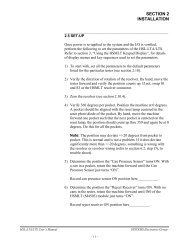
SECTION 3<br />
SYSTEM CONFIGURATION<br />
The system configuration defines the <strong>M4500</strong> module configuration that the program will run in.<br />
This includes enabling or disabling the input0 and input1 interrupts, and enabling or disabling the<br />
timed interrupt. These parameters are all set through SYSdev when the program is developed. See<br />
the SYSdev Programming Manual for more details.<br />
________________________________________________________________________________<br />
3.1 TARGET BOARD<br />
This is used to select the module that the program will be loaded into. For all the <strong>M4500</strong> modules,<br />
this parameter is always set to <strong>M4500</strong>. Within the <strong>M4500</strong> product family, the SYSdev software<br />
package does not distinguish between the different modules (M4503, M4508, etc.). Any differences<br />
in features of the various modules is exploited within the user program code (i.e. memory mapped<br />
I/O updates, etc.)<br />
________________________________________________________________________________<br />
3.2 INPUT0 INTERRUPT ENABLE<br />
If the Input0 interrupt is to be used, it must be enabled in the system configuration. The input0<br />
interrupt calls ufunc00 when activated, thus the user must create ufunc00. The ufunc00 file is<br />
created and executed just like any other user function file with the exception that it is called when<br />
the input0 interrupt input makes an "off" to "on" transition, instead of being called from the main<br />
user program. If the input0 interrupt is disabled, interrupt input0 can be used as a standard input<br />
(see section 6.5).<br />
________________________________________________________________________________<br />
3.3 INPUT1 INTERRUPT ENABLE<br />
If the Input1 interrupt is to be used, it must be enabled in the system configuration. The input1<br />
interrupt calls ufunc01 when activated, thus the user must create ufunc01. The ufunc01 file is<br />
created and executed just like any other user function file with the exception that it is called when<br />
the input1 interrupt input makes an "off" to "on" transition, instead of being called from the main<br />
user program. If the input1 interrupt is disabled, interrupt input1 can be used as a standard input<br />
(see section 6.5).<br />
<strong>M4500</strong> Program Development Manual<br />
SYSTEMS Electronics Group<br />
- 7 -
SECTION 3<br />
SYSTEM CONFIGURATION<br />
________________________________________________________________________________<br />
3.4 TIMED INTERRUPT<br />
If the timed interrupt file is to be used, it must be enabled in the system configuration. The timed<br />
interrupt interval must also be set between 0.250 and 65.000 milliseconds. The timed interrupt file<br />
will be called at these intervals, thus the user must create the timed interrupt file. The timed<br />
interrupt file is created and executed just as any other file with the exception that it is executed at<br />
the specified interval (by interrupting the main program).<br />
Note: The actual timed interrupt execution time must be less than the selected timed interrupt time,<br />
otherwise a main program scan watchdog time out will occur.<br />
<strong>M4500</strong> Program Development Manual<br />
SYSTEMS Electronics Group<br />
- 8 -
SECTION 4<br />
VARIABLE TYPES/MEMORY MAP<br />
________________________________________________________________________________<br />
4.1 VARIABLES<br />
Three classes of variables are used in the <strong>M4500</strong>. They are: bits, bytes, and words. Bits are a single<br />
bit in width and can have a value of 0 or 1. Bytes are 8 bits in width and can have a value between 0<br />
and 255 decimal or 0 and ffH hex. Words are 16 bits in width and can have a value of 0 to 65535<br />
decimal or 0 to ffffH hex. All numbers (values in variables and constants) are unsigned integer<br />
values. No signed or floating point numbers are supported. Numbers can be represented as decimal<br />
or hex (suffix 'H' following number).<br />
Three different variable types are available in the <strong>M4500</strong>: flags (F), bytes (B), and words (W).<br />
________________________________________________________________________________<br />
4.1.1 Flags (F)<br />
Flags are single bit variables which are generally used as internal coils or flags in the user program.<br />
Flags can have a value of "0" or "1". The <strong>M4500</strong> module contains 992 flags.<br />
The format of the flag variable is:<br />
Fzzz where: zzz is a three digit flag address (000 to 991).<br />
Note: The leading 'F' must be a capital letter.<br />
Examples: F0, F12, F103, etc.<br />
<strong>M4500</strong> Program Development Manual<br />
SYSTEMS Electronics Group<br />
- 9 -
SECTION 4<br />
VARIABLE TYPES/MEMORY MAP<br />
________________________________________________________________________________<br />
4.1.2 Bytes (B)<br />
Byte variables are 8 bit variables used as general purpose variables in the user program. Byte<br />
variables can have a value between 0 and 255 decimal or 0 and ffH hex. Byte variables are used as<br />
arithmetic variables in the High-level language, timer/counter presets and accumulators as well as<br />
shift register bytes in the ladder language. The <strong>M4500</strong> module contains 6,764 'B' variables.<br />
The format of the byte variable is:<br />
Bzzz where: zzz is the three digit byte address (32 thru 7151).<br />
Note: The leading 'B' must be a capital letter.<br />
Examples: B32, B150, B201, etc.<br />
Individual bits within the byte can also be referenced by simply appending a '.' followed by the bit<br />
number (0-7) to the byte address. The form of this is:<br />
Bzzz.y where: zzz is the byte address and y is the bit (0-7).<br />
This allows any bit in the entire data memory to be referenced just as a flag is referenced. These<br />
"byte.bit" variables can be used in ladder blocks as contact and coil variables as well as in the Highlevel<br />
blocks. Execution times for instructions that use bits within a byte that is addressed at B512 to<br />
B7151 are longer than execution times for instructions using flags or byte addresses between B32<br />
and B151. Keep this in mind when using "byte.bit" references.<br />
Examples: B80.0, B100.7, B72.4, etc.<br />
<strong>M4500</strong> Program Development Manual<br />
SYSTEMS Electronics Group<br />
- 10 -
SECTION 4<br />
VARIABLE TYPES/MEMORY MAP<br />
________________________________________________________________________________<br />
4.1.3 Words (W)<br />
Word variables are 16 bit variables used as general purpose variables in the user program. Words<br />
can have a value between 0 and 65535 decimal or 0 and ffffH hex. Word variables are used as<br />
arithmetic variables in the High-level language. The <strong>M4500</strong> module contains 3,382 'W' variables.<br />
The format of the word variable is:<br />
Wzzz where: zzz is the three digit word address (32 thru 7150).<br />
Note: The leading 'W' must be a capital letter. Also, word addresses are always an even number<br />
(divisible by 2).<br />
Examples: W34, W1500, W6050, etc.<br />
________________________________________________________________________________<br />
4.1.4 Constants<br />
Constants are used as fixed numbers in High-level arithmetic and conditional statements as well as<br />
for presets in timer/counters in ladder blocks.<br />
In High-level blocks, constants can be represented in decimal or hex. If the number is decimal, the<br />
constant is simply entered as the number to be referenced. No prefix or suffix is specified. If the<br />
number is hex, the suffix 'H' is added immediately following the hex number. Examples of both are:<br />
25 (decimal)<br />
25657 (decimal)<br />
aeH (hex)<br />
f000H (hex)<br />
The hex letters (a,b,c,d,e,f) are case sensitive and must be typed as lower case letters. The hex suffix<br />
is also case sensitive and must be typed as a capital letter (H).<br />
All constants are unsigned integers. When the variable class is byte, the range of values is 0 to 255<br />
decimal or 0 to ffH hex. If the variable class is word, the range of values is 0 to 65535 decimal or 0<br />
to ffffH hex.<br />
In ladder blocks, the only constants allowed are in timer/counter presets. In this case, they are<br />
specified in decimal and preceded with the prefix '#'.<br />
<strong>M4500</strong> Program Development Manual<br />
SYSTEMS Electronics Group<br />
- 11 -
SECTION 4<br />
VARIABLE TYPES/MEMORY MAP<br />
________________________________________________________________________________<br />
4.2 DATA MEMORY MAP<br />
The memory map of the <strong>M4500</strong> data memory is shown below:<br />
Address Valid Variable References Battery Backed<br />
0032 F000-F007 B032 W032 no<br />
0033 F008-F015 B033 ------ no<br />
0034 F016-F023 B034 W034 no<br />
0035 F024-F031 B035 ------ no<br />
thru thru thru thru<br />
0154 F976-F983 B154 W154 no<br />
0155 F984-F991 B155 ------ no<br />
0512 --------- B512 W512 yes<br />
0513 --------- B513 ------ yes<br />
thru thru thru thru<br />
7150 --------- B7150 W7150 yes<br />
7151 --------- B7151 ------ yes<br />
<strong>M4500</strong> Program Development Manual<br />
SYSTEMS Electronics Group<br />
- 12 -
SECTION 4<br />
VARIABLE TYPES/MEMORY MAP<br />
________________________________________________________________________________<br />
4.2.1 NON-BATTERY BACKED DATA MEMORY (B32-B155)<br />
The lower 124 bytes of data memory (B32 thru B155) are not battery backed and will not retain<br />
data at power down. At power-up or reset, these addresses are cleared.<br />
Note: Flags F0 thru F991 are mapped into bytes B32 thru B155. Bytes B32 thru B155 are also<br />
mapped into words W32 thru W154. These addresses can be referenced as any or all three of these<br />
variable types. The flags are mapped into the bytes as shown as follows:<br />
F000 = B32.0<br />
F001 = B32.1<br />
F002 = B32.2<br />
F003 = B32.3<br />
F004 = B32.4<br />
F005 = B32.5<br />
F006 = B32.6<br />
F007 = B32.7<br />
F008 = B33.0<br />
F009 = B33.1<br />
F010 = B33.2<br />
etc.<br />
The bytes are mapped into the words with even byte addresses as the low byte (lower 256<br />
significance) of the respective word and the odd byte address as the upper byte (upper 256<br />
significance) of the word as shown:<br />
B32 = W32 (low byte)<br />
B33 = W32 (high byte)<br />
________________________________________________________________________________<br />
4.2.2 BATTERY BACKED DATA MEMORY (B512-B7151)<br />
The upper 6,640 bytes of data memory (B512 thru B7151) are battery backed such that all data<br />
residing in this part of memory at power down is retained while power is "off". At power-up these<br />
addresses are not cleared, retaining the data that was present before power down. The data in this<br />
memory space can also be saved on disk using the data upload menu selection from the SYSdev<br />
Target Board Interface menu. The data saved on disk can be downloaded to the <strong>M4500</strong> at a later<br />
time if necessary. See the SYSdev Program Development Manual for details.<br />
The upper group of memory is referenced as bytes (B) or words (W), no flags are resident in this<br />
area of memory. However, any bit within this area can be referenced using the "byte.bit" format<br />
outlined in section 4.1.2. The byte (B) variables are mapped into the word (W) variables just as they<br />
are in the lower group of memory.<br />
<strong>M4500</strong> Program Development Manual<br />
SYSTEMS Electronics Group<br />
- 13 -
SECTION 4<br />
VARIABLE TYPES/MEMORY MAP<br />
________________________________________________________________________________<br />
4.3 SPECIAL FUNCTION VARIABLES (SFV's) (Directly addressed)<br />
Many of the features of the <strong>M4500</strong> are accessed via certain variables in the <strong>M4500</strong>. These are<br />
referred to as "Special Function Variables" (SFV). Most of the SFV's are fully defined in the related<br />
sections that pertain to the function or feature that the respective SFV is used. Section 4.5 defines<br />
the System Enable Flags in B161 in detail. The following is a <strong>com</strong>plete list of SFV's of the <strong>M4500</strong>.<br />
Address<br />
Description<br />
B160<br />
PLS Command Flags:<br />
B160.0 Execute PLS <strong>com</strong>mand (from PLC)<br />
B160.1 Reserved (Do not access)<br />
thru<br />
B160.5 Reserved (Do not access)<br />
B160.6 Bypass "Recall" Ack<br />
B160.7 Reserved (Do not access)<br />
B161<br />
System Enable Flags:<br />
B161.0 PLS Mode Enable<br />
B161.1 PLS CH0-7 Speed Compensation Enable<br />
B161.2 PLS Keypad Commands Enable<br />
B161.3 Analog I/O Update Enable<br />
B161.4 PLS Update in TIMED(1)/ PLS Update in MAIN(0)<br />
B161.5 PLS Program Commands Enable<br />
B161.6 sfunc13 slave mode enable in S4516<br />
B161.7 sfunc18 interleaved(0)/ executed <strong>com</strong>plete(1)<br />
W162 AIN0 - Analog Input 0 (0-1023)<br />
W164 AIN1 - Analog Input 1 (0-1023)<br />
B166 AOUT0 - Analog Output 0 (0-255)<br />
B167 AOUT1 - Analog Output 1 (0-255)<br />
B170<br />
B171<br />
B172<br />
B173<br />
B174<br />
B175<br />
B176<br />
B177<br />
CH0 PLS Channel byte 0 (CH00-07)<br />
CH1 PLS Channel byte 1 (CH10-17)<br />
CH2 PLS Channel byte 2 (CH20-27)<br />
CH3 PLS Channel byte 3 (CH30-37)<br />
CH4 PLS Channel byte 4 (CH40-47)<br />
CH5 PLS Channel byte 5 (CH50-57)<br />
CH6 PLS Channel byte 6 (CH60-67)<br />
CH7 PLS Channel byte 7 (CH70-77)<br />
<strong>M4500</strong> Program Development Manual<br />
SYSTEMS Electronics Group<br />
- 14 -
SECTION 4<br />
VARIABLE TYPES/MEMORY MAP<br />
Address<br />
W178<br />
W180<br />
W182<br />
W184<br />
W186<br />
W188<br />
W192<br />
Description<br />
Resolver Position (updated in TIMED Interrupt)<br />
Resolver Position (updated in MAIN Program)<br />
Resolver RPM<br />
Resolver Period (msec per revolution)<br />
Resolver Scale Factor<br />
Resolver Offset<br />
Resolver Period (speed <strong>com</strong>pensation)<br />
B191<br />
Depressed Key on Keypad (0=no key, 1-24=key)<br />
B194 Display wait delay (B194=28 for D4590, B194=47 for D4591)<br />
B8158<br />
Keypad Debounce time (in main scans)<br />
W8154<br />
W8156<br />
B8159<br />
Slave Slot Address for S4516 sfunc13 slave mode<br />
S4516 Slot Address for sfunc10/11/13<br />
Current Firmware Revision<br />
PLS Programming (from PLC) SFV's:<br />
B190 Selected PLS Channel Program (0-7)<br />
B212<br />
PLS Command:<br />
B212=09: Recall Channel<br />
B212=27: Single set-point programming <strong>com</strong>mand<br />
B212=43: Pulse Train Programming <strong>com</strong>mand<br />
For Recall Channel <strong>com</strong>mand:<br />
B213<br />
Channel to read (set by user prior to <strong>com</strong>mand)<br />
B213<br />
Recall State (0="off", 1="on") (return value)<br />
W214<br />
Position of set-point change of state (return value)<br />
For Single set-point <strong>com</strong>mand:<br />
B213<br />
Channel to program set-point<br />
W214<br />
"ON" setpoint (in degrees)<br />
W216<br />
"OFF" setpoint (in degrees)<br />
B218<br />
Program state (0="off", 1="on")<br />
For Pulse Train <strong>com</strong>mand:<br />
B213<br />
Channel to program set-point<br />
W214<br />
"START" position (in degrees)<br />
B216<br />
"ON" Duration<br />
B217<br />
"OFF" Duration<br />
General PLS registers:<br />
W246<br />
Current Recall position (used be "Recall" <strong>com</strong>mand to indicate last position<br />
that change of channel state occurred - location to search from)<br />
B204.0 "Set-point" <strong>com</strong>mand active<br />
B204.1 "Pulse Train" <strong>com</strong>mand active<br />
B204.2 "Select Channel" <strong>com</strong>mand active<br />
B204.3 "Set Config" <strong>com</strong>mand Active<br />
Note: The bits in B204 indicate when the respective PLS programming <strong>com</strong>mand is active and can<br />
be reset unconditionally to defeat the respective PLS <strong>com</strong>mand.<br />
<strong>M4500</strong> Program Development Manual<br />
SYSTEMS Electronics Group<br />
- 15 -
SECTION 4<br />
VARIABLE TYPES/MEMORY MAP<br />
________________________________________________________________________________<br />
4.4 SPECIAL FUNCTION VARIABLES (SFV's) (Indirectly addressed)<br />
Address<br />
Description<br />
2100H Number of PLS Channels (8,16,32,64)<br />
2120H<br />
Resolver Scale Factor (battery backed)<br />
2122H<br />
Resolver Offset (battery backed)<br />
2124H<br />
Selected PLS Program (battery backed)<br />
2126H<br />
CH0 Speed Compensation (active)<br />
2127H<br />
CH1 Speed Compensation (active)<br />
2128H<br />
CH2 Speed Compensation (active)<br />
2129H<br />
CH3 Speed Compensation (active)<br />
212aH<br />
CH4 Speed Compensation (active)<br />
212bH<br />
CH5 Speed Compensation (active)<br />
212cH<br />
CH6 Speed Compensation (active)<br />
212dH<br />
CH7 Speed Compensation (active)<br />
2146H<br />
Current PLS Channel selected for programming<br />
________________________________________________________________________________<br />
4.5 SYSTEM ENABLE FLAGS (B161)<br />
The System Enable Flags allow fundamental features of the <strong>M4500</strong> to be enabled or disabled<br />
dependent on the requirements of the specific application. This allows the overhead scan time to be<br />
optimized to the absolute minimum based on the actual features required. The System Enable Flags<br />
are located in B161. Individual flags can be set or reset by addressing the individual bits using the<br />
"byte.bit" format. The following is <strong>com</strong>plete description of each flag:<br />
B161.0 - PLS Mode Enable: This flag is used to enable or disable the entire PLS section of the<br />
<strong>M4500</strong>. In applications which do not require the PLS (modules without the resolver interface, i.e.<br />
M4501, M4502, M4509, M4513), setting this flag to a "0" will disable the PLS section. In this case<br />
none of the firmware (code) relating to the PLS will be executed thus reducing the overhead scan<br />
time accordingly. If the PLS is to be used, then B161.0 must be set to a "1". The PLS feature will<br />
then function normally. At power up, B161.0 is set to a "0" disabling the PLS section. If the PLS is<br />
to be used, B161.0 should be set to "1" inside the user's "Init" file.<br />
B161.1 - PLS CH0-7 Speed Compensation Enable: This flag is used to enable the speed<br />
<strong>com</strong>pensation of CH0 thru CH07 of the PLS section (see section 3.1.5 of the <strong>M4500</strong> User's<br />
Manual). If B161.1 is set to "0", speed <strong>com</strong>pensation on these channels will be disabled. If B161.1<br />
is set to "1", the speed <strong>com</strong>pensation will be enabled. At power up, B161.1 is set to a "0" disabling<br />
the speed <strong>com</strong>pensation. If speed <strong>com</strong>pensation is to be used, B161.1 should be set to "1" inside the<br />
user's "Init" file. B161.1 has no effect if B161.0 is not set to a "1".<br />
<strong>M4500</strong> Program Development Manual<br />
SYSTEMS Electronics Group<br />
- 16 -
SECTION 4<br />
VARIABLE TYPES/MEMORY MAP<br />
B161.2 - PLS Keypad Commands Enable: This flag is used to enable the D4590 and D4591<br />
Display/Keypads as the standard PLS programming keypad (see section 4 of the <strong>M4500</strong> User's<br />
Manual). If B161.2 is set to "0", the display can be used as a general purpose Display/Keypad with<br />
the function of all the keys and display defined by the user program. If B161.2 is set to "1", the<br />
Display/Keypad will function as a PLS programmer with the keys defined as outlined in section 4<br />
of the <strong>M4500</strong> User's manual and the display automatically updated by the firmware of the <strong>M4500</strong><br />
with PLS prompts as necessary. At power up, B161.1 is set to a "0" disabling the Display/Keypad<br />
as a PLS programmer. If the Display/Keypad is to be used as a PLS programmer, B161.2 should be<br />
set to "1" inside the user's "Init" or "Main Program" file.<br />
B161.3 - Analog I/O Update Enable: This flag is used to enable the conversion of the analog<br />
I/O (both the two inputs and two outputs) built into the <strong>M4500</strong>. If B161.3 is set to "0", the analog<br />
I/O conversion will be bypassed, reducing the overhead scan time accordingly. If B161.3 is set to<br />
"1", then the analog input conversion will be performed, each input every other scan, with the<br />
converted analog input values stored in W162 and W164 for AIN0 and AIN1 respectively. Both<br />
analog outputs will be updated on each scan. At power up, B161.3 is set to a "0" disabling the<br />
analog input update. If the analog input update is to be performed, B161.3 should be set to "1"<br />
inside the user's "Init" file.<br />
B161.4 - PLS Update in TIMED(1)/PLS Update in MAIN(0): This flag determines whether<br />
the PLS position and channel update will occur in either the timed interrupt file or main program<br />
file. The PLS channel update is equivalent to the input update on standard inputs. The PLS channel<br />
update consists of reading the resolver position (with the corresponding scale factor and offset<br />
applied) and setting all the PLS channels to the appropriate "0" or "1" state depending on the user<br />
programming of these channels at the current position.<br />
If B161.4 is set to a "0", the PLS channel update will be performed at the beginning of each Main<br />
Program scan and W180 will be set to the current position. If B161.4 is set to a "1", the PLS<br />
channel update will be performed at the beginning of each Timed Interrupt scan and W178 will be<br />
set to the current position. At power up, B161.4 is set to a "0", enabling the PLS channel update in<br />
the Main Program scan. If the channel update is to be done in the Timed Interrupt, B161.4 should<br />
be set to "1" inside the user's "Init" file. B161.4 has no effect if B161.0 is not set to a "1".<br />
B161.5 - PLS Program Commands Enable: This flag is used to enable or disable the<br />
programming keys of the D4590 or D4591 Display/Keypads when these are used as the standard<br />
PLS programming Keypad (B161.2 set to "1"). The <strong>com</strong>mands disabled when B161.5 is set to a "0"<br />
are: "CONF" which includes setting the scale factor, offset, selecting the PLS program, number of<br />
timing channels and the speed <strong>com</strong>pensation for CH00 thru CH07, "ENTER SET-POINT",<br />
"PULSE TRAIN", and "CLEAR CHAN".<br />
<strong>M4500</strong> Program Development Manual<br />
SYSTEMS Electronics Group<br />
- 17 -
SECTION 4<br />
VARIABLE TYPES/MEMORY MAP<br />
The primary purpose of B161.5 is to allow only authorized personnel to alter the parameters of the<br />
PLS section by use of a keyed switch which is input to standard input of the <strong>M4500</strong> and mapped to<br />
B161.5. When the switch is in the "disable" position, B161.5 would be set to a "0", defeating the<br />
use of the <strong>com</strong>mand keys. When the switch is in the "enable" position, B161.5 would be set to a<br />
"1", and the <strong>com</strong>mand keys would function as normal. At power up, B161.5 is set to a "0" disabling<br />
the PLS program <strong>com</strong>mand keys. B161.5 has no effect if B161.0 and B161.2 are not both set to a<br />
"1".<br />
B161.6 - sfunc13 slave mode enable in S4516: This flag enables the slave mode response to<br />
<strong>com</strong>munications from other <strong>M4500</strong> or S3000 products using the S3000 network (see section 6.3).<br />
This flag is used in conjunction with the S4516 <strong>com</strong>munications board installed in the <strong>M4500</strong> rack.<br />
When B161.6 is set to "0", the network slave response firmware is disabled, reducing the overhead<br />
scan time accordingly. The <strong>M4500</strong> will not respond to any messages sent from master S3000 or<br />
<strong>M4500</strong> nodes trying to <strong>com</strong>municate with the <strong>M4500</strong>. If B161.6 is set to "1", then the network slave<br />
response is enabled and the <strong>M4500</strong> will accept <strong>com</strong>munications from other nodes. At power up,<br />
B161.6 is set to a "0" disabling the network slave <strong>com</strong>munications. If the <strong>M4500</strong> is to act as a slave<br />
on the S3000 network, B161.6 should be set to "1" inside the user's "Init" file.<br />
B161.7 - sfunc18 interleaved(0)/executed <strong>com</strong>plete (1): See section 6.1 for <strong>com</strong>plete<br />
details on the use of this flag.<br />
<strong>M4500</strong> Program Development Manual<br />
SYSTEMS Electronics Group<br />
- 18 -
SECTION 4<br />
VARIABLE TYPES/MEMORY MAP<br />
________________________________________________________________________________<br />
4.6 MEMORY MAPPED I/O<br />
'X' and 'Y' variables are not supported in the <strong>M4500</strong>. Instead the I/O slots of the chassis are mapped<br />
into the memory space of the <strong>M4500</strong>, accessed as Byte(B) variables. The addresses of the different<br />
slots are assigned as follows:<br />
Group-Slot Byte Address<br />
0-0 0 B7424<br />
1 B7425<br />
2 B7426<br />
3 B7427<br />
0-1 0 B7488<br />
1 B7489<br />
2 B7490<br />
3 B7491<br />
0-2 0 B7552<br />
1 B7553<br />
2 B7554<br />
3 B7555<br />
0-3 0 B7616<br />
1 B7617<br />
2 B7618<br />
3 B7619<br />
1-0 0 B7680<br />
1 B7681<br />
2 B7682<br />
3 B7683<br />
1-1 0 B7744<br />
1 B7745<br />
2 B7746<br />
3 B7747<br />
1-2 0 B7808<br />
1 B7809<br />
2 B7810<br />
3 B7811<br />
1-3 0 B7872<br />
1 B7873<br />
2 B7874<br />
3 B7875<br />
<strong>M4500</strong> Program Development Manual<br />
SYSTEMS Electronics Group<br />
- 19 -
SECTION 4<br />
VARIABLE TYPES/MEMORY MAP<br />
Unlike the S3000 and M4000, the <strong>M4500</strong> does not automatically perform the I/O update at the<br />
beginning of the program. The I/O update on the <strong>M4500</strong> is performed by the user's program. This<br />
allows an increased flexibility in how the I/O is updated. To update the I/O, the user should assign<br />
some internal Byte(B) variables which will serve as the I/O image (same function as the 'X' and 'Y'<br />
variables performed). Input boards are read and stored in the input image (B) bytes while output<br />
image (B) bytes are used to store the value of the outputs and then are written to the outputs.<br />
Separate input image bytes should be used for the main program and the timed interrupt if the timed<br />
interrupt is used. The same output image bytes can be used in the main program and timed interrupt<br />
provided the (B) byte addresses used for the output image are at addresses B32 thru B155. If output<br />
image (B) bytes are used in the address ranges B512 thru B7151, then separate output image bytes<br />
should be used for the main program and timed interrupt.<br />
Note: The I/O addresses are broken up into two groups of 4 I/O slots each. The I/O address dip<br />
switches on the I/O boards consist of two poles which allows the board to be addressed from 0 to 3<br />
(00=0, 01=1, 10=2, and 11=3). The I/O dip switches on the I/O board determine the actual slot the<br />
board is addressed as, not the physical slot location in the group the board resides in. Thus within a<br />
group, there are 4 unique possible I/O addresses. All the input boards within a group must have<br />
unique I/O slot addresses and all the output boards within a group must have unique I/O slot<br />
addresses. However an all input board can share the same I/O slot address as an all output board<br />
since the input board is read from only and the output board is written to only. This technique<br />
allows more than four slots to exist in one group which is the case on the 12 slot M4512 and M4513<br />
chassis.<br />
The following <strong>M4500</strong> modules contain the corresponding I/O groups and slots within each group:<br />
Chassis<br />
<strong>M4500</strong> (PLC/PLS)<br />
M4501 (PLC only)<br />
M4502 (PLC only)<br />
M4503 (PLC/PLS)<br />
M4508 (PLC/PLS)<br />
M4509 (PLC only)<br />
M4512 (PLC/PLS)<br />
M4513 (PLC only)<br />
I/O Groups<br />
Group0 - 4 I/O slots<br />
Group0 - 4 I/O slots<br />
Group0 - 3 I/O slots<br />
Group0 - 3 I/O slots<br />
Group0 - 4 I/O slots<br />
Group1 - 4 I/O slots<br />
Group0 - 4 I/O slots<br />
Group1 - 4 I/O slots<br />
Group0 - 4 I/O slots<br />
Group1 - 8 I/O slots<br />
Group0 - 4 I/O slots<br />
Group1 - 8 I/O slots<br />
<strong>M4500</strong> Program Development Manual<br />
SYSTEMS Electronics Group<br />
- 20 -
SECTION 5<br />
<strong>PROGRAM</strong>MING LANGUAGE REFERENCE<br />
The following sections provide an overview of the SYSdev instruction set and the system functions<br />
available in the <strong>M4500</strong> module. See the SYSdev Programming Manual for more details on the<br />
SYSdev programming language and the operation of the SYSdev software package.<br />
________________________________________________________________________________<br />
5.1 INSTRUCTION SET<br />
________________________________________________________________________________<br />
5.1.1 LADDER<br />
The ladder language is generally used to implement the boolean logic of the user program.<br />
Networks of virtually any form (including nested branches) can be implemented. Ladder blocks are<br />
implemented as a 7 row X 9 column matrix. The following ladder instructions are available:<br />
1) Contacts 4) Counters<br />
- Normally open<br />
- Normally closed 5) Shift Registers<br />
2) Coils 6) Box Instructions<br />
- Standard - Add/Subtract<br />
- Latch - Mult/Divide<br />
- Unlatch - AND/OR/XOR<br />
- Inverted - Shift Left/Right<br />
- Compare (>,>=,==)<br />
3) Timers - Move/Invert<br />
- scan time base - ufunc Call<br />
- 0.01 sec time base - Network Comm<br />
- 0.10 sec time base<br />
- 1.00 sec time base<br />
Valid variables for contacts and coils are flags (F) or bits out of bytes (B).<br />
Valid variables for timer/counter presets and accumulators are bytes (B) and words (W). The<br />
maximum preset is 255 for bytes (B) and 65535 for words (W).<br />
Valid variables for shift registers are also bytes (B) and words (W). The number of shifts per<br />
variable is 7 for bytes (B) and 15 for words (W).<br />
<strong>M4500</strong> Program Development Manual<br />
SYSTEMS Electronics Group<br />
- 21 -
SECTION 5<br />
<strong>PROGRAM</strong>MING LANGUAGE REFERENCE<br />
________________________________________________________________________________<br />
5.1.2 HIGH-LEVEL ('C')<br />
The High-level language is a subset of the 'C' programming language. High-level is used for all<br />
arithmetic, <strong>com</strong>parisons, conditional program execution, program looping, calling user functions<br />
(subroutines) and calling system functions (I/O operations). High-level blocks are implemented as a<br />
57 row X 80 column text array.<br />
The High-level language incorporates the following:<br />
1) Operators:<br />
+ :add ++ :increment<br />
- :subtract -- :decrement<br />
* :multiply == :equate<br />
/ :divide > :greater than<br />
% :remainder >= :greater than or equal<br />
> :right shift
SECTION 5<br />
<strong>PROGRAM</strong>MING LANGUAGE REFERENCE<br />
________________________________________________________________________________<br />
5.2 SYSTEM FUNCTIONS<br />
System functions provide the user with a means to perform extended functions such as<br />
<strong>com</strong>munication on the serial network, etc. A summary of the system functions available in the<br />
<strong>M4500</strong> module is as follows:<br />
sfunc03: watch dog timer reset<br />
sfunc04: ASCII string load<br />
sfunc09: system fault routine<br />
sfunc10: USER PORT receive<br />
sfunc11: USER PORT transmit<br />
sfunc13: serial network <strong>com</strong>munications<br />
sfunc18: display write (update)<br />
sfunc19: S4516 configuration<br />
System functions are entered in high-level blocks as text. Each system function has a parameter list<br />
associated with the system function call which defines such things as the address to read/write to,<br />
the number of bytes to send/receive, etc. In addition, some system functions return with an error<br />
code or function status which can be used to determine if the system function was successful, busy,<br />
etc.<br />
________________________________________________________________________________<br />
5.2.1 SYSTEM FUNCTION TYPES<br />
Two types of system functions exist: suspended and simultaneous.<br />
Suspended System Function: Suspended system functions actually suspend program<br />
execution while they are executed. Thus they are performed just as any other type of instruction, in<br />
order of sequence in which they occur.<br />
Simultaneous System Functions: Simultaneous system functions are executed simultaneously<br />
to program execution. By their nature, simultaneous system functions may take multiple main<br />
program scans to execute. These are basically "back-ground" tasks which are executed while the<br />
user application program is executing, with insignificant impact on the user program scan time.<br />
<strong>M4500</strong> Program Development Manual<br />
SYSTEMS Electronics Group<br />
- 23 -
SECTION 5<br />
<strong>PROGRAM</strong>MING LANGUAGE REFERENCE<br />
The simultaneous system function returns with one of four types of return values when called: Not<br />
Busy, Busy, Done or an error code representing a fault in the execution of the function. When the<br />
function is first executed, a return value of "Busy" is returned. This indicates the function is<br />
executing and is no longer available for use until it has <strong>com</strong>pleted. Subsequent calls to the same<br />
system function will result in a "Busy" return value until the function has <strong>com</strong>pleted. At that time, a<br />
call to the system function will result in either a "Done" return value or an error code value<br />
representing a failure of the function to execute. The system function is now available to execute<br />
again. See the individual system function formats following for more details on the return values<br />
and error codes pertinent to each system function.<br />
________________________________________________________________________________<br />
5.2.2 sfunc03: watchdog timer reset<br />
System function 03 resets the main program watchdog timer when called. The watchdog timer<br />
normally times out if the main program scan time is longer than 100msec. This function can be used<br />
to extend this time by 100msec every time sfunc03 is called. This is desirable, for instance, if a<br />
long, intentional program loop ("for" loop, "while" loop, etc.) is executed which would exceed the<br />
normal 100msec scan time.<br />
General form:<br />
Parameters:<br />
Return Value:<br />
Type:<br />
Valid Files:<br />
sfunc03();<br />
none<br />
none<br />
suspended<br />
Initialization, Main Program, Timed Interrupt, and user functions.<br />
<strong>M4500</strong> Program Development Manual<br />
SYSTEMS Electronics Group<br />
- 24 -
SECTION 5<br />
<strong>PROGRAM</strong>MING LANGUAGE REFERENCE<br />
________________________________________________________________________________<br />
5.2.3 sfunc04: ASCII string load <strong>com</strong>mand<br />
System function 04 is used to convert the characters in an ASCII string to their equivalent ASCII<br />
codes and store these codes in consecutive byte addresses in variable memory (Bxxx variables).<br />
System function 04 is typically used in conjunction with the display sfunc18 write (update) system<br />
function to write ASCII strings to the display.<br />
General form:<br />
sfunc04(dest,"string");<br />
Parameters: dest = The address where the first ASCII character of the string will be stored. The<br />
remaining ASCII characters will be stored in consecutive byte addresses following<br />
the first byte address. Variable types: 'B'.<br />
string = The string is from one to 60 printable characters. These characters will be converted<br />
to their equivalent ASCII codes and stored in consecutive byte addresses starting at<br />
the dest byte address.<br />
Note: The string must be enclosed with double quotes as shown (these double<br />
quotes are not stored as part of the string, but simply used as delimiters for the<br />
string). Any printable character can be incorporated in the string with the exception<br />
of the double quote " or back slash \. If these two characters are to be incorporated<br />
in the string, they must be preceded with the back slash (i.e. \" will incorporate the "<br />
only and \\ will incorporate just one \).<br />
Return Value:<br />
Type:<br />
Valid Files:<br />
none<br />
suspended<br />
Initialization, Main Program, Timed Interrupt, and user functions.<br />
Examples 1) sfunc04(B100,"example #1");<br />
The above example will load the following byte addresses with the corresponding<br />
ASCII codes (numbers):<br />
B100 = 101<br />
B101 = 120<br />
B102 = 97<br />
B103 = 109<br />
B104 = 112<br />
B105 = 108<br />
B106 = 101<br />
B107 = 32<br />
B108 = 35<br />
B109 = 49<br />
(101= ACSII code for 'e')<br />
(120= ACSII code for 'x')<br />
(97= ACSII code for 'a')<br />
(109= ACSII code for 'm')<br />
(112= ACSII code for 'p')<br />
(108= ACSII code for 'l')<br />
(101= ACSII code for 'e')<br />
(32= ACSII code for space)<br />
(35= ACSII code for '#')<br />
(49= ACSII code for '1')<br />
2) sfunc04(B150,":");<br />
The above example will load B150 with 58 which is the ASCII code for ':'.<br />
<strong>M4500</strong> Program Development Manual<br />
SYSTEMS Electronics Group<br />
- 25 -
SECTION 5<br />
<strong>PROGRAM</strong>MING LANGUAGE REFERENCE<br />
3) sfunc04(B1500,"MOTOR \"on\"");<br />
The above example incorporates double quotes in the string and uses the back<br />
slash to designate that these double quotes are part of the string and not the string<br />
delimiters. The characters are stored in non-volatile memory as follows:<br />
B1500 = 77<br />
(77= ASCII code for 'M')<br />
B1501 = 79<br />
(79= ASCII code for 'O')<br />
B1502 = 84<br />
(84= ASCII code for 'T')<br />
B1503 = 79<br />
(79= ASCII code for 'O')<br />
B1504 = 82<br />
(82= ASCII code for 'R')<br />
B1505 = 32<br />
(32= ASCII code for space)<br />
B1506 = 34 (34= ASCII code for ")<br />
B1507 = 111<br />
(111= ASCII code for 'o')<br />
B1508 = 110<br />
(110= ASCII code for 'n')<br />
B1509 = 34 (34= ASCII code for ")<br />
________________________________________________________________________________<br />
5.2.4 sfunc09: system fault routine<br />
System function 09 provides a means for the fault routine to be called in response to a software<br />
detected fault from the user application program. The fault routine is executed as described in<br />
section 6.1 of the <strong>M4500</strong> User's Manual. The fault code will be set to "45H: sfunc09 generated<br />
fault".<br />
Note: This function should only be called when a <strong>com</strong>plete system shutdown is desired due to the<br />
fact that program execution will cease.<br />
General form:<br />
Parameters:<br />
Return value:<br />
Type:<br />
Valid files:<br />
sfunc09();<br />
none<br />
none<br />
non-returning<br />
Initialization, Main Program, and User functions.<br />
<strong>M4500</strong> Program Development Manual<br />
SYSTEMS Electronics Group<br />
- 26 -
SECTION 5<br />
<strong>PROGRAM</strong>MING LANGUAGE REFERENCE<br />
________________________________________________________________________________<br />
5.2.5 sfunc10: USER PORT receive<br />
System function 10 receives a consecutive number of bytes from the USER PORT. See section<br />
6.4.1 for a detailed description of the use of sfunc10.<br />
Note: sfunc10 is used in conjunction with the S4516 <strong>com</strong>munications board. See section 5.2.9 for<br />
details on configuring the S4516.<br />
General form:<br />
sfunc10(#max,dest);<br />
Parameters: #max = This defines the size of the "dest" receive buffer. In essence, this is the maximum<br />
number of bytes which can be received between sfunc10 calls. Variable types:<br />
constant (1-250), 'B' or indirect 'B'.<br />
dest = The address of the first byte of the sfunc10 receive buffer. The receive buffer is<br />
where the bytes received from the USER PORT will be stored. Variable types: 'B'<br />
or indirect 'B'.<br />
Return Value:<br />
Type:<br />
Valid Files:<br />
The return value of sfunc10 is the number of bytes which have been received from<br />
the USER PORT and stored in the "dest" receive buffer. Unlike sfunc10 in other<br />
S3000 boards and M4000 modules, the return value is not BUSY, DONE, or an<br />
error code. Once sfunc10 is called, the USER port indefinitely waits for data to be<br />
sent to it.<br />
simultaneous<br />
Initialization, Main Program, and user functions.<br />
<strong>M4500</strong> Program Development Manual<br />
SYSTEMS Electronics Group<br />
- 27 -
SECTION 5<br />
<strong>PROGRAM</strong>MING LANGUAGE REFERENCE<br />
________________________________________________________________________________<br />
5.2.6 sfunc11: USER PORT transmit<br />
System function 11 transmits a consecutive number of bytes out the USER PORT. See Section 6.4.2<br />
for a detailed description of the use of sfunc11.<br />
Note: sfunc11 is used in conjunction with the S4516 <strong>com</strong>munications board. See section 5.2.9 for<br />
details on configuring the S4516.<br />
General form:<br />
sfunc11(#sent,srce);<br />
Parameters: #sent = The number of bytes to transmit out the USER PORT. Variable types: constant (1-<br />
250), 'B' or indirect 'B'.<br />
srce = The address where the first byte transmitted is stored. A consecutive number of<br />
bytes (= #sent) is transmitted out the USER PORT starting with this address.<br />
Variable types: 'B' or indirect 'B'.<br />
Return Values:<br />
Type:<br />
Valid Files:<br />
0 = NOT BUSY/READY<br />
1 = BUSY<br />
2 = DONE (transmit successful)<br />
34 = Invalid S4516 slot address (prior to executing sfunc11, W8156 must be loaded<br />
with the address the S4516 is in - see section 4.6)<br />
simultaneous<br />
Initialization, Main Program, and user functions.<br />
<strong>M4500</strong> Program Development Manual<br />
SYSTEMS Electronics Group<br />
- 28 -
SECTION 5<br />
<strong>PROGRAM</strong>MING LANGUAGE REFERENCE<br />
________________________________________________________________________________<br />
5.2.7 sfunc13: serial network <strong>com</strong>munications<br />
System function 13 is used to <strong>com</strong>municate to other S3012s, S3014s, M4000 modules, or other<br />
<strong>M4500</strong> nodes on the serial <strong>com</strong>munication network. See section 6.3 for details on the use of<br />
sfunc13 and a description of the serial network.<br />
Note: sfunc13 is used in conjunction with the S4516 <strong>com</strong>munications board. See section 5.2.9 for<br />
details on configuring the S4516.<br />
General form:<br />
sfunc13(slave,#sent,m_srce,s_dest,#rcve,s_srce,m_dest);<br />
Parameters: slave = Address of node to <strong>com</strong>municate with. This is the network address of the slave,<br />
each slave has a unique address. Variable type: constant (1-32), 'B' or indirect 'B'.<br />
#sent = Number of words to send to slave. Variable types: constant (0-120), 'B' or indirect<br />
'B'.<br />
m_srce = Address of source stack in master which will be sent to slave. A consecutive<br />
number of words (= #sent) will be sent to the slave starting at this address.<br />
Variable type: 'W' or indirect 'W'.<br />
s_dest = Starting address of destination stack in slave where words sent from master will<br />
be stored. Variable type: 'W' or indirect 'W'.<br />
#rcve = Number of words received from slave. Variable type: constant (0-120), 'B' or<br />
indirect 'B'.<br />
s_srce = Starting address of source stack in slave where words will be sent from slave to<br />
master. Variable type: 'W' or indirect 'W'.<br />
m_dest = Starting destination address in master where words sent from slave will be stored.<br />
Variable type: 'W' or indirect 'W'.<br />
Return values: 0 = NOT BUSY/READY<br />
1 = BUSY<br />
2 = DONE (<strong>com</strong>m with slave successful)<br />
3-10H = ERROR CODE (see section 6.4.1 of the <strong>M4500</strong> User's Manual for serial network<br />
<strong>com</strong>munication error code descriptions).<br />
22H = Invalid S4516 slot address (prior to executing sfunc13, W8156 must be loaded<br />
with the address the S4516 is in - see section 4.6)<br />
Type:<br />
Valid files:<br />
simultaneous<br />
Initialization, Main Program, and user functions<br />
<strong>M4500</strong> Program Development Manual<br />
SYSTEMS Electronics Group<br />
- 29 -
SECTION 5<br />
<strong>PROGRAM</strong>MING LANGUAGE REFERENCE<br />
________________________________________________________________________________<br />
5.2.8 sfunc18: display write (update)<br />
System function 18 writes a consecutive number of bytes to the display. See Section 6.1 for a<br />
detailed description of the use of sfunc18.<br />
General form:<br />
sfunc18(#sent,srce);<br />
Parameters: #sent = The number of bytes to write to the display. Variable types: constant (1-250), 'B' or<br />
indirect 'B'.<br />
srce = The address where the first byte written is stored. A consecutive number of bytes<br />
(= #sent) is written to the display starting with this address. Variable types: 'B' or<br />
indirect 'B'.<br />
Return Values:<br />
0 = NOT BUSY/READY<br />
1 = BUSY<br />
2 = DONE (display updated)<br />
Type: simultaneous with B161.7 set to "0", suspended with B161.7 set to "1".<br />
Valid Files:<br />
Initialization, Main Program, and user functions.<br />
<strong>M4500</strong> Program Development Manual<br />
SYSTEMS Electronics Group<br />
- 30 -
SECTION 5<br />
<strong>PROGRAM</strong>MING LANGUAGE REFERENCE<br />
________________________________________________________________________________<br />
5.2.9 sfunc19: S4516 configuration<br />
System function 19 is used to set the S4516 configuration (Network address, Network Baud rate,<br />
and USER PORT Baud rate). This must be executed prior to executing either sfunc10, sfunc11, or<br />
sfunc13 (generally sfunc19 is executed in the "Init" file of the user program).<br />
Note: For sfunc10, sfunc11, sfunc13, and sfunc19, W8156 must be loaded with the address of the<br />
S4516 (byte0 of the group and slot that the S4516 resides in - see section 4.6) just prior to the<br />
execution of the sfunc (i.e.):<br />
W8156 = 7424; /* S4516 in slot0, byte0 */<br />
sfunc19(...);<br />
This informs the sfunc which slot to execute the system function with.<br />
Note: Multiple S4516s can be installed in one chassis. However, a particular sfunc can act on only<br />
one S4516 at a time. Once a system function is initiated with an S4516, a return value of DONE or<br />
ERROR must be received before the sfunc can be executed on a different S4516.<br />
The format of the sfunc19 is as follows:<br />
sfunc19(sta_addr,net_baud,user_baud);<br />
Parameters: sta_addr = Network station address (1-32) as is normally defined for the S3000 network.<br />
Variable types: constant (1-32), 'B' or indirect 'B'.<br />
net_baud = Network baud rate (1=106K, 2=228K, 3=344K). Variable types: constant (1,2,3),<br />
'B' or indirect 'B'.<br />
user_baud = USER PORT baud rate (0=9600 baud, 1=19.2K baud). Variable types: constant<br />
(0 or 1), 'B' or indirect 'B'.<br />
Return Values:<br />
1 = BUSY<br />
2 = DONE (S4516 successfully configured)<br />
3 = INVALID Parameter (either station address, network baud, or USER port baud<br />
rate was invalid)<br />
4 = TIMEOUT (no response from S4516)<br />
32 = Hardware ACK error from S4516<br />
34 = Invalid S4516 slot address (prior to executing sfunc19, W8156 must be loaded<br />
with the address the S4516 is in - see section 4.6)<br />
<strong>M4500</strong> Program Development Manual<br />
SYSTEMS Electronics Group<br />
- 31 -
SECTION 5<br />
<strong>PROGRAM</strong>MING LANGUAGE REFERENCE<br />
(This Page Intentionally Left Blank)<br />
<strong>M4500</strong> Program Development Manual<br />
SYSTEMS Electronics Group<br />
- 32 -
SECTION 6<br />
USING SYSTEM FUNCTIONS<br />
________________________________________________________________________________<br />
6.1 WRITING (UPDATING) THE DISPLAY<br />
The D4590 and D4591 Display/Keypads of the <strong>M4500</strong> contain a separate display processor which<br />
actually controls and updates the display. The processor of the <strong>M4500</strong> transmits data and control<br />
codes to the display processor via sfunc18. This system function is similar to sfunc11 in that the<br />
number of bytes to be transmitted to the display and the starting address of these bytes are specified<br />
in the system function.<br />
The data sent to the display is a <strong>com</strong>bination of ASCII characters which are to be displayed on the<br />
display and control codes which actual control the display (such as "clear" display, position cursor,<br />
etc.). Section 6.1.2 contains a list of the display control codes and sections 6.1.3 contains a table of<br />
the valid ASCII characters which can be displayed on the display. Both the ASCII data and the<br />
control codes are sent to the display via sfunc18. The data and control codes can be intermixed in<br />
one sfunc18 call as necessary.<br />
System function 18 can be implemented as either a simultaneous or suspended system function<br />
based on the setting of the System Enable flag B161.7. When B161.7 is set to a "0", sfunc18 will<br />
function as a simultaneous system function such that once initiated, a return value of BUSY (1) or<br />
DONE (2) is returned based on whether the display update is <strong>com</strong>plete or still in progress. New data<br />
cannot be sent to the display until the last update is <strong>com</strong>plete (return = DONE). In this mode, one<br />
byte of data is sent to the display every scan, thus requiring multiple scans to update the display.<br />
If B161.7 is set to a "1", sfunc18 will function as a suspended system function such that program<br />
execution is suspended at the sfunc18 until all the data has been sent to the display.<br />
Note: The display can only except the data sent to it at rate no faster then 28 microseconds per byte<br />
for the D4590 and 48 microseconds per byte for the D4591. This delay time is set in the display<br />
wait delay SFV B194 (B194 should be set to 28 for the D4590 and 48 for the D4591). The amount<br />
of time sfunc18 suspends program execution when executed in this mode is equal to the number of<br />
bytes sent to the display times the wait delay. System function 18 will always return with a return<br />
value of DONE (2) in this mode.<br />
<strong>M4500</strong> Program Development Manual<br />
SYSTEMS Electronics Group<br />
- 33 -
SECTION 6<br />
USING SYSTEM FUNCTIONS<br />
________________________________________________________________________________<br />
6.1.1 WRITING DATA TO THE DISPLAY (sfunc18)<br />
Using sfunc18, from 1 to 250 consecutive bytes can be written to the display in one <strong>com</strong>mand.<br />
System function 18 can be executed as either a simultaneous system function (B161.7=0) or a<br />
suspended system function (B161.7=1).<br />
If executed as simultaneous function, once initiated, program execution continues without waiting<br />
for the sfunc to <strong>com</strong>plete. Subsequent calls of sfunc18 result in a return value of "BUSY" until the<br />
sfunc <strong>com</strong>pletes (return = "DONE"). In this mode, since sfunc18 is a simultaneous function, the<br />
impact on the user application program scan time is negligible when an sfunc18 is executed.<br />
However, since only one byte is written to the display per scan, the update of the display will be<br />
slower with the characters actually being seen written out across the display. See example #1 below.<br />
If executed as a suspended function, program execution will be suspended until the display update<br />
is <strong>com</strong>plete. This will have an impact on the scan time proportional to the number of bytes written<br />
to the display. However, the display will now update much quicker and implementation of<br />
sophisticated display drivers is usually easier in this mode. See example #2 below.<br />
The general form of sfunc18 is: sfunc18(#send,srce); where "#send" is the number of bytes to write<br />
and "srce" is the starting address of the stack of bytes that will be written to the display. Prior to<br />
executing the sfunc18 call, the "srce" buffer is formatted, by the user program, with the appropriate<br />
control codes and ASCII character codes. The ASCII character codes can be generated using the<br />
sfunc04 ASCII string load <strong>com</strong>mand. Both examples #1 and #2 below give examples of formatting<br />
the "srce" buffer.<br />
Examples:<br />
1) if (F2 == 1) /* update display */<br />
{<br />
B100 = 1fH; /* position cursor control code */<br />
B101 = 5bH; /* line 2 - location 27 */<br />
B102 = 0cH; /* display "on", cursor "off" <strong>com</strong>mand */<br />
B103 = 30H; /* write character "0" */<br />
B104 = 32H: /* write character "2" */<br />
if (sfunc18(5,B100) == 2) /* update display */<br />
F2 = 0;<br />
}<br />
execution:<br />
The above code writes the characters "02" starting at location 27 of line 2 in the display.<br />
Note: F2 would be set to "1" somewhere else in the user program to perform the display update.<br />
F2 stays at "1" until the display update is <strong>com</strong>plete. The user program could then monitor F2 to<br />
determine when the display is available (F2 = 0) or BUSY (F2 = 1). This is an example of using<br />
sfunc18 in the simultaneous mode.<br />
<strong>M4500</strong> Program Development Manual<br />
SYSTEMS Electronics Group<br />
- 34 -
SECTION 6<br />
USING SYSTEM FUNCTIONS<br />
2) B2000 = 1fH; /* position cursor control code */<br />
B2001 = 00H; /* line 1 - location 0 */<br />
sfunc04(B2002,"....message to be displayed in line 1....");<br />
sfunc18(42,B2000); /* write line 1 to display */<br />
B2000 = 1fH; /* position cursor control code */<br />
B2001 = 40H; /* line 2 - location 0 */<br />
sfunc04(B2002,"....message to be displayed in line 2....");<br />
sfunc18(42,B2000); /* write line 2 to display */<br />
execution:<br />
The above writes the entire display (both lines) using an sfunc18 <strong>com</strong>mand for each line. The<br />
cursor is positioned to the first character position of each line prior to writing the ascii message<br />
for the respective line.<br />
Note: The sfunc04s were used to convert the characters "message to be displayed"..etc. to the<br />
equivalent ACSII codes into the addresses used as the sfunc18 buffer. These sfunc04s should<br />
contain 40 characters each (using spaces to fill in unused display positions) if the entire display<br />
is to be updated in one sfunc18 call. This is an example of using sfunc18 in the suspended<br />
mode.<br />
<strong>M4500</strong> Program Development Manual<br />
SYSTEMS Electronics Group<br />
- 35 -
SECTION 6<br />
USING SYSTEM FUNCTIONS<br />
________________________________________________________________________________<br />
6.1.2 DISPLAY CONTROL CODES<br />
The following is a list of valid display control codes. Care should be taken not to send undefined<br />
control codes to the display as this may cause unpredictable display operation.<br />
CODE - BINARY (HEX) DESCRIPTION<br />
76543210<br />
00000001 (01H) Reset display, clear enter display area, position cursor at first line, first<br />
character (execution time 1.64msec)<br />
00000010 (02H) Reset display, position cursor at first line, first character (execution time<br />
1.64msec)<br />
000001DS<br />
00001DCB<br />
0001SR00<br />
Entry Mode:<br />
Specify Cursor Direction:<br />
D = 0: Decrement<br />
D = 1: Increment<br />
Display Shift Mode:<br />
S = 0: Display Shift "off"<br />
S = 1: Display Shift "on"<br />
Display ON/OFF:<br />
D = 0: Display "off"<br />
D = 1: Display "on"<br />
Cursor:<br />
C = 0: Cursor "off"<br />
C = 1: Cursor "on"<br />
Blinking of Character at Cursor Position:<br />
B = 0: Blinking "off"<br />
B = 1: Blinking "on"<br />
Display/Cursor Shift:<br />
S = 0: Move Cursor<br />
S = 1: Shift Display<br />
R = 0: Shift Right<br />
R = 1: Shift Left<br />
00011111 (1fH) Set cursor position: two byte <strong>com</strong>mand, second byte is cursor position.<br />
<strong>M4500</strong> Program Development Manual<br />
SYSTEMS Electronics Group<br />
- 36 -
SECTION 6<br />
USING SYSTEM FUNCTIONS<br />
________________________________________________________________________________<br />
6.1.3 VALID DISPLAYED CHARACTERS<br />
The following is a chart showing the valid character codes which can be displayed on the display.<br />
The ASCII character codes 20H thru 7dH can be generated using the sfunc04 ASCII string load<br />
<strong>com</strong>mand. Examples of this are in example #2 of section 6.1.1.<br />
<strong>M4500</strong> Program Development Manual<br />
SYSTEMS Electronics Group<br />
- 37 -
SECTION 6<br />
USING SYSTEM FUNCTIONS<br />
________________________________________________________________________________<br />
6.2 KEYPAD INTERFACE<br />
The keypad of the D4590 and D4591 Display/Keypads are 3-row by 8-column sealed keypads. Key<br />
depressed decode is performed automatically during the I/O update at the beginning of the main<br />
program scan. The key number depressed is automatically updated in SFV byte B191. The<br />
corresponding number for each key is shown in figure 6.1. If no key is depressed, B191 is set to<br />
zero. If a key is depressed, B191 equals the key number as long as the key is depressed. In this way,<br />
the user program can monitor B191 for a depressed key, generating leading and trailing edge<br />
transitions of key depression with user logic if desired.<br />
Figure 6.1 - Keypad Key Assignments<br />
<strong>M4500</strong> Program Development Manual<br />
SYSTEMS Electronics Group<br />
- 38 -
SECTION 6<br />
USING SYSTEM FUNCTIONS<br />
________________________________________________________________________________<br />
6.3 SERIAL NETWORK COMMUNICATIONS (sfunc13)<br />
The serial network provides a means for multiple S3012s, S3014s, M4000 modules or <strong>M4500</strong><br />
modules (hereafter referred to as nodes) to <strong>com</strong>municate with each other. The network operates in a<br />
master/slave topology. One module acts as the master node and controls all <strong>com</strong>munications on the<br />
network. The remaining nodes act as slaves and simply respond to <strong>com</strong>munications requests from<br />
the master. The master can send up to 120 consecutive words and receive up to 120 consecutive<br />
words from a slave in one <strong>com</strong>mand. If data is to be sent from one slave to another slave, it must be<br />
done through the master (i.e. the master reads the data from the first slave and then sends it to the<br />
second slave).<br />
Up to 32 S3012s, S3014s, M4000 modules, <strong>M4500</strong> modules or other S3000 network <strong>com</strong>patible<br />
boards can be installed on one network. These 32 nodes consist of the one master and up to 31<br />
slaves. Each node on the network is assigned a unique network address. This number is a number<br />
between 1 and 32. The network address is used to specify which slave the master is <strong>com</strong>municating<br />
to. The network address of an <strong>M4500</strong> module is set via sfunc19 (see section 5.2.9).<br />
________________________________________________________________________________<br />
6.3.1 COMMUNICATING ON THE NETWORK (sfunc13)<br />
System function 13 is used to execute the <strong>com</strong>munications <strong>com</strong>mand to the slave. The parameter<br />
list of sfunc13 contains:<br />
1) Slave network address to <strong>com</strong>municate to.<br />
2) Number of words to be sent to slave.<br />
3) Starting address of stack, in master, of words which will be sent to slave (m_srce).<br />
4) Starting address of stack, in slave, where the words are to be stored (s_dest).<br />
5) Number of words to be received from slave.<br />
6) Starting address of stack, in slave, where the words will be sent from (s_srce).<br />
7) Starting address of stack, in master, where the words from the slave will be stored (m_dest).<br />
See section 5.2.7 for a <strong>com</strong>plete description of the above parameters, the general form of sfunc13<br />
and the return values possible with sfunc13.<br />
Note: sfunc13 is used only in the master, the slaves respond to network <strong>com</strong>munications<br />
<strong>com</strong>pletely transparently. No <strong>com</strong>mands are added to the slave programs in order to implement the<br />
serial network. Thus, only one program (the master's) in the entire network has any <strong>com</strong>mands<br />
pertaining to network <strong>com</strong>munications.<br />
<strong>M4500</strong> Program Development Manual<br />
SYSTEMS Electronics Group<br />
- 39 -
SECTION 6<br />
USING SYSTEM FUNCTIONS<br />
System function 13 is a simultaneous function such that once it is initiated, program execution<br />
continues without waiting for the sfunc to <strong>com</strong>plete. Subsequent calls of sfunc13 result in a return<br />
value of "BUSY" until the sfunc <strong>com</strong>pletes (return = "DONE") or detects an error (return =<br />
"ERROR CODE"). See section 6.4.1 of the <strong>M4500</strong> User's Manual for a description of the serial<br />
network error codes. Since sfunc13 is a simultaneous function, the impact on the user application<br />
program scan time is negligible when executed. This is also true for the responding slave. Reception<br />
and transmission on the serial network occurs concurrently with program execution, no significant<br />
increase in the scan time of the slave occurs when a slave is <strong>com</strong>municated with.<br />
The sequence of events in a serial network <strong>com</strong>m event are as follows:<br />
1) Master node initiates <strong>com</strong>m event by executing an sfunc13. Program execution in the master<br />
proceeds concurrently with the transmission of the words to the slave.<br />
2) The slave receives the words from the master concurrently with it's program execution. Once all<br />
words are received from the master, the slave starts transmission of the words that are to be sent<br />
from the slave to the master. This also occurs concurrently with the slave program execution.<br />
3) The master receives the words sent from the slave concurrently with it's program execution. Once all<br />
the words from the slave have been received, the subsequent call to sfunc13 results in a return<br />
value of "DONE". Until this step, calls to sfunc13 would have resulted in a "BUSY" return value.<br />
In the case of the <strong>M4500</strong>, the S3000 network is implemented using the optional S4516<br />
<strong>com</strong>munications board. This board provides one S3000 network <strong>com</strong>munications port and one RS-<br />
232 USER port. System function 19 must be executed to initialize the S4516 prior to performing<br />
any network <strong>com</strong>munications as either a master or a slave. This initializes both the network address<br />
and the network baud rate of the <strong>M4500</strong> module.<br />
If the <strong>M4500</strong> is to be used as a slave on the S3000 network, System Enable flag B161.6 must be set<br />
to "1". This activates the network slave firmware of the <strong>M4500</strong>, allowing it to respond to<br />
<strong>com</strong>munication requests from other network nodes.<br />
Examples:<br />
1) Initializing S4516 for <strong>com</strong>munications (S4516 board located in slot02):<br />
W8156 = 7552; /* S4516 located in Slot02 */<br />
sfunc19(5,3,1); /* S4516 initialized to network node = 5, */<br />
/* network baud = 344K, USER port baud */<br />
/* rate = 19.2K */<br />
<strong>M4500</strong> Program Development Manual<br />
SYSTEMS Electronics Group<br />
- 40 -
SECTION 6<br />
USING SYSTEM FUNCTIONS<br />
2) Communicating from an <strong>M4500</strong> to a slave node:<br />
Master <strong>M4500</strong> main program:<br />
B070 = sfunc13(4,10,W1000,W1200,5,W1250,W1100);<br />
execution:<br />
The above <strong>com</strong>mand transmits the 10 words W1000 thru W1018 in the master <strong>M4500</strong> to the<br />
slave at network address 4, storing the data in W1200 thru W1218. The slave then transmits 5<br />
words (W1250 thru W1258) to the master, storing this data in W1100 thru W1108. The<br />
transmission of the data was done concurrently with the program executions of both the master<br />
and the slave.<br />
The return value of the sfunc13 is stored in B070. Once the sfunc13 is initiated, the return value<br />
of the sfunc13 is "BUSY" (B070 = 1) until the transmission is <strong>com</strong>plete. At that time, the return<br />
value is "DONE" (B070 = 2) or an error code (B070 = ERROR CODE) if an error occurred in<br />
transmission.<br />
________________________________________________________________________________<br />
6.4 USER PORT COMMUNICATIONS<br />
The USER PORT is a general purpose RS-232/RS-422 port available on the S4516 <strong>com</strong>munications<br />
board for connection to any RS-232/RS-422 user devices. Communications through the USER<br />
PORT is achieved using sfunc10 (USER PORT read) and sfunc11 (USER PORT write). These<br />
sfuncs allow any ASCII codes from 0 to 255 to be read from or written to the port. The port is<br />
configured as follows: baud rate of 9600 or 19.2K, 1 start bit, 8 data bits, 1 stop bit and no parity.<br />
The USER PORT can be selected as either RS-232 or RS-422 (but not both). This is done by setting<br />
a dip switch on the S4516 board (see the S4516 data sheet).<br />
Note: Different pins on the USER PORT connector are used for the RS-232 lines and RS-422 lines<br />
(see the S4516 data sheet).<br />
<strong>M4500</strong> Program Development Manual<br />
SYSTEMS Electronics Group<br />
- 41 -
SECTION 6<br />
USING SYSTEM FUNCTIONS<br />
________________________________________________________________________________<br />
6.4.1 RECEIVING THROUGH THE USER PORT (sfunc10)<br />
Note: sfunc10 functions differently on the <strong>M4500</strong> than it does on other S3000 boards or M4000<br />
modules. With other S3000/M4000 boards, sfunc10 must receive the exact number of bytes<br />
specified in the sfunc10 call from the user device within a time-out period. In the other<br />
S3000/M4000 boards, the return value of sfunc10 specifies whether the sfunc10 is still "BUSY"<br />
(has not received the number of bytes specified yet), is "DONE" (all bytes received), or timed-out<br />
(not all bytes were sent within the time-out period).<br />
For the <strong>M4500</strong>, calling sfunc10 essentially enables the USER PORT to receive data from the user<br />
device indefinitely. The format of sfunc10 for the <strong>M4500</strong> is sfunc10(#max,dest);. Using sfunc10,<br />
any number of bytes can be read from a user's ASCII device through the USER port. The return<br />
value of the sfunc10 in the <strong>M4500</strong> is the number of bytes received since the last sfunc10 call. The<br />
bytes that were received are saved in the buffer specified by "dest" in the sfunc10 call.<br />
Note: This buffer should be considered a temporary buffer such that if a string of bytes was<br />
expected to be received, the bytes would be "stripped" off this buffer as they were received and<br />
saved at some other address locations. The "#max" is the maximum number of bytes that can be<br />
saved in the temporary buffer before an overflow occurs. This should be set higher then the<br />
maximum number of bytes that can be received between sfunc10 calls.<br />
The operation of sfunc10 in the <strong>M4500</strong> allows for a much more flexible format then the previous<br />
use of sfunc10 in the other S3000/M4000 boards. With this format, any number of bytes can be sent<br />
from the user device at any time. No software handshaking is then required. Also, it is much easier<br />
to make the <strong>M4500</strong> the slave to the user device then the previous format used.<br />
In the case of the <strong>M4500</strong>, sfunc19 must be executed to initialize the S4516 prior to performing<br />
ufunc10. This initializes the USER PORT baud rate as desired (the default baud rate is 9600 Baud).<br />
See section 5.2.5 for the general form and parameter list of sfunc10.<br />
Examples:<br />
1) Initializing S4516 for <strong>com</strong>munications (S4516 board located in slot02):<br />
W8156 = 7552; /* S4516 located in Slot02 */<br />
sfunc19(5,3,1); /* S4516 initialized to network node = 5, */<br />
/* network baud = 344K, USER port baud */<br />
/* rate = 19.2K */<br />
<strong>M4500</strong> Program Development Manual<br />
SYSTEMS Electronics Group<br />
- 42 -
SECTION 6<br />
USING SYSTEM FUNCTIONS<br />
2) Receiving through the USER PORT:<br />
B080 = sfunc10(10,B100);<br />
execution:<br />
The above enables the USER PORT to receive data from the user device through the USER<br />
PORT. The sfunc10 specifies that the temporary receive buffer is 10 bytes long located at B100<br />
through B109. The return value in B080 is the number of bytes received since the last call to<br />
sfunc10 occurred. As an example, assume 3 bytes were received since the last call of sfunc10,<br />
these bytes would be loaded into B100, B101, and B102 as they were received. B080 would be<br />
set to 3 after the sfunc10 was executed. With B080 = 3, it is now necessary to read B100, B101,<br />
and B102 and store them in some other locations since this data will be lost the next time the<br />
sfunc10 is called.<br />
________________________________________________________________________________<br />
6.4.2 TRANSMITTING THROUGH THE USER PORT (sfunc11)<br />
Using sfunc11, from 1 to 250 consecutive bytes can be transmitted out the USER PORT in one<br />
<strong>com</strong>mand. System function 11 is a simultaneous function such that once it is initiated, program<br />
execution continues without waiting for the sfunc to <strong>com</strong>plete. Subsequent calls of sfunc11 result in<br />
a return value of "BUSY" until the sfunc <strong>com</strong>pletes (return = "DONE"). Since sfunc11 is a<br />
simultaneous function, the impact on the user application program scan time is negligible when an<br />
sfunc11 is executed.<br />
The general form of sfunc11 is: sfunc11(#send,srce); where "#send" is the number of bytes to<br />
transmit and "srce" is the starting address of the stack of bytes that will be transmitted. When<br />
sfunc11 is initiated, the data in "srce" is loaded into the S4516 <strong>com</strong>munications board and then<br />
transmitted out the USER PORT of the S4516.<br />
In the case of the <strong>M4500</strong>, sfunc19 must be executed to initialize the S4516 prior to performing<br />
ufunc10. This initializes the USER PORT baud rate as desired (the default baud rate is 9600 Baud).<br />
Example:<br />
1) B080 = sfunc11(6,B120);<br />
execution:<br />
The above transmits the 6 bytes between B120 and B125 out the USER PORT. The return value<br />
of sfunc11 is stored in B080. When sfunc11 is first called, the return value will equal "BUSY"<br />
(B080 = 1). Subsequent calls of sfunc11 will result in a "BUSY" (B080 = 1) return value until all 6<br />
bytes have been transmitted, at which time a return value of "DONE" (B080 = 2) is obtained.<br />
Note: Program execution is not suspended while sfunc11 is executing. Once initiated, program<br />
execution continues with subsequent calls of sfunc11 determining when all the bytes have<br />
actually been transmitted. The time it takes for sfunc11 to <strong>com</strong>plete is a function of the number<br />
of bytes to be transmitted and the selected Baud rate of the USER PORT.<br />
<strong>M4500</strong> Program Development Manual<br />
SYSTEMS Electronics Group<br />
- 43 -
SECTION 6<br />
USING SYSTEM FUNCTIONS<br />
________________________________________________________________________________<br />
6.5 USING IN0/IN1 INTERRUPT INPUTS AS STANDARD INPUTS<br />
The INPUT0 and INPUT1 interrupt inputs built into the <strong>M4500</strong> can be used as standard inputs<br />
instead of interrupt inputs by inserting the following assembly lines into either the main program<br />
file or timed interrupt depending on where the inputs are to be updated:<br />
jbs PORT0,7,in0_1; map IN0 to F80<br />
andb B42,#0feh<br />
sjmp in0_2<br />
in0_1: orb B42,#01h<br />
in0_2:<br />
jbs HSI_STATUS,1,in1_1; map IN1 to F81<br />
andb B42,#0fdh<br />
sjmp in1_2<br />
in1_1: orb B42,#02h<br />
in1_2:<br />
The above assembly block maps IN0 to F80 (B42.0) and IN1 to F81 (B42.1) respectively. IN0 and<br />
IN1 can be mapped to any flags desired but note that the flags are accessed as bits within a byte by<br />
masking the corresponding bit within that byte to a "0" or a "1". Reminder: Assembly blocks are<br />
created by using the "F12: Insert Assembly" selection from the main program editor screen of<br />
SYSdev.<br />
<strong>M4500</strong> Program Development Manual<br />
SYSTEMS Electronics Group<br />
- 44 -