Propane(LP) Space Heater - World Marketing of America, Inc.
Propane(LP) Space Heater - World Marketing of America, Inc.
Propane(LP) Space Heater - World Marketing of America, Inc.

You also want an ePaper? Increase the reach of your titles
YUMPU automatically turns print PDFs into web optimized ePapers that Google loves.
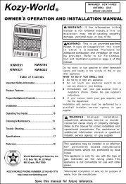
Kozy-<strong>World</strong>R<br />
INFRARED VENT-FREE<br />
PROPANE/<strong>LP</strong> GAS<br />
SPACE HEATER<br />
OWNER’S OPERATION AND INSTALLATION MANUAL<br />
KWP110 KWP112 KWP122<br />
Table <strong>of</strong> Contents<br />
Important Safety Information.................................2<br />
Product Features.....................................................3<br />
Proper Ventilation & Fresh Air..............................4<br />
Installation................................................................6<br />
Operating Your <strong>Heater</strong>............................................10<br />
Cleaning & Maintenance.......................................13<br />
Trouble Shooting...................................................14<br />
Specifications..........................................................17<br />
Parts List..................................................................18<br />
WARNING: If the information in this<br />
manual is not followed exactly, a fire or<br />
explosion may result causing property<br />
damage, personal injury, or loss <strong>of</strong> life.<br />
WARNING: This is an unvented gasfired<br />
heater. It uses air (oxygen) from the<br />
room in which it is installed. Provisions<br />
for adequate combustion and ventilation<br />
air must be provided. Refer to Air<br />
For Combustion and Ventilation section on<br />
page 4 <strong>of</strong> this manual.<br />
<strong>World</strong> <strong>Marketing</strong> <strong>of</strong> <strong>America</strong>, <strong>Inc</strong>.<br />
P.O. Box 192, Rt. 22 West<br />
Mill Creek, PA 17060<br />
KOZY WORLD PHONE NUMBER: (814) 643-1775<br />
http://www.worldmkting.com<br />
Do not store, or use gasoline or other flammable<br />
vapors and liquids in the vicinity <strong>of</strong> this or any<br />
other appliance.<br />
WHAT TO DO IF YOU SMELL GAS<br />
• Do not try to light any appliance.<br />
• Do not touch any electrical switch; do not<br />
use any phone in your building.<br />
• Immediately call your gas supplier from a<br />
neighbor’s phone. Follow the gas supplier’s<br />
instructions.<br />
• If you cannot reach your gas supplier, call<br />
the fire department.<br />
Installation and service must be performed by a<br />
qualified installer, service agency or gas<br />
supplier.<br />
WARNING: Improper installation,<br />
adjustment, alteration, service or maintenance<br />
can cause injury or property damage.<br />
Refer to this manual for correct installation and<br />
operational procedures. For assistance or<br />
additional information consult a qualified<br />
installer, service agency, or gas supplier.<br />
This appliance may be installed in an aftermarket*<br />
permanently located, manufactured<br />
(mobile) home, where not prohibited by local<br />
codes.<br />
This appliance is only for use with the type <strong>of</strong><br />
gas indicated on the rating plate. This<br />
appliance is not convertible for use with other<br />
gases.<br />
WATER VAPOR: A BY-PRODUCT OF UNVENTED ROOM<br />
HEATERS<br />
Water vapor is a by-product <strong>of</strong> gas combustion.An<br />
unvented room heater productes approximately one (1)<br />
ounce (30ml) <strong>of</strong> water for every 1,000 BTU’s (.3KW’s) <strong>of</strong><br />
gas input per hour. Refer to page 3.<br />
*Aftermarket: Completion <strong>of</strong> sale, not for purpose <strong>of</strong><br />
resale, from the manufacturer.<br />
Installer: Please leave these instructions with the<br />
consumer.<br />
Consumer: Please retain these instructions for<br />
future use.<br />
KW-ML062-14W-0504
IMPORTANT<br />
SAFETY INFORMATION<br />
WARNINGS<br />
IMPORTANT: Read this<br />
owner’s manual carefully and<br />
completely before trying to<br />
assemble, operate, or service<br />
this heater. Improper use <strong>of</strong><br />
this heater can cause serious<br />
injury or death from burns,<br />
fire, explosion, electrical<br />
shock, and carbon monoxide<br />
poisoning.<br />
WARNING: Do not use any<br />
accessory not approved for<br />
use with this heater.<br />
WARNING: Any change to<br />
this heater or its controls can<br />
be dangerous.<br />
Do not place clothing or other<br />
flammable material on or near<br />
the appliance. Never place any<br />
objects on the heater.<br />
Due to high temperatures, heater<br />
should be kept out <strong>of</strong><br />
traffic and away from furniture<br />
and draperies.<br />
Surface <strong>of</strong> heater becomes<br />
very hot when running heater.<br />
Keep children and adults away<br />
from hot surface to avoid burns<br />
or clothing ignition. <strong>Heater</strong> will<br />
remain hot for a time after shut<br />
down. Allow surface to cool<br />
before touching.<br />
Carefully supervise young<br />
children when they are in the<br />
same room with heater.<br />
Make sure grill guard is in<br />
place before running the heater.<br />
State <strong>of</strong> Massachusetts: The<br />
installation must be made by a licensed<br />
plumber or gas fitter in the<br />
Commonwealth <strong>of</strong> Massachusetts.<br />
Sellers <strong>of</strong> unvented propane or natural<br />
gas-fired supplemental room heaters<br />
shall provide to each purchaser a<br />
copy <strong>of</strong> 527 CMR 30 upon sale <strong>of</strong> the<br />
unit.<br />
In the state <strong>of</strong> Massachusetts,<br />
unvented propane or nature gas-fired<br />
space heaters shall be prohibited in<br />
bedrooms and bathrooms.<br />
Keep the appliance area clear<br />
and free from combustible<br />
materials, gasoline, and other<br />
flammable vapors and liquids.<br />
WARNING<br />
Modeles KWP110, KWP112,<br />
KWP122 are equipped for propane<br />
gas. Field conversion is not<br />
permitted.<br />
1. This appliance is only for use<br />
with the type <strong>of</strong> gas indicated<br />
on the rating plate. This<br />
appliance is not convertible for<br />
use with other gases.<br />
2. Do not place propane/<strong>LP</strong><br />
supply tank(s) inside any<br />
structure. Locate propane/<strong>LP</strong><br />
supply tank(s) outside.<br />
3. If you smell gas<br />
• Shut <strong>of</strong>f gas supply.<br />
• Do not try to light any appliance.<br />
• Do not touch any electrical switch;<br />
do not use any phone in your<br />
building.<br />
• Immediately call your gas sup<br />
plier from a neighbor’s phone.<br />
Follow the gas supplier’s<br />
instructions.<br />
• If you cannot reach your gas<br />
supplier, call the fire<br />
department.<br />
4. Always run heater with control<br />
knob at LOW or HIGH locked<br />
positions. Never set control<br />
knob between locked positions.<br />
Poor combustion and higher<br />
levels <strong>of</strong> carbon monoxide may<br />
result.<br />
5. This heater needs fresh,<br />
outside air ventilation to run<br />
properly. This heater has an<br />
Oxygen Depletion Sensor<br />
(ODS) safety shut<strong>of</strong>f system.<br />
The ODS shuts down the<br />
heater if not enough fresh air<br />
is available. See Fresh Air for<br />
Combustion and Ventilation<br />
pages 4 and 5.<br />
6. Keep all air openings in front<br />
and bottom <strong>of</strong> heater clear<br />
and free <strong>of</strong> debris. This will<br />
insure enough air for proper<br />
combustion.<br />
7. If heater shuts <strong>of</strong>f. Do not<br />
relight until you provide fresh,<br />
outside air. If heater keeps<br />
shutting <strong>of</strong>f, have it serviced.<br />
8. Do not operate heater<br />
• where flammable liquids or vapors<br />
are used or stored<br />
• under dusty conditions<br />
2<br />
9. Do not install models KWP112 and<br />
KWP122 in a bathroom.<br />
10. Before using furniture polish,<br />
wax, carpet cleaner, or similar<br />
products, turn heater <strong>of</strong>f. If heated,<br />
the vapors from these products<br />
may create a white powder<br />
residue within burner box or on<br />
adjacent walls or furniture.<br />
11. Do not use heater if any part<br />
has been under water.<br />
Immediately call a qualified<br />
service technician to inspect<br />
the room heater and to<br />
replace any part <strong>of</strong> the control<br />
system and any gas control<br />
which has been under water.<br />
12. Turn <strong>of</strong>f heater and let cool<br />
before servicing. Only a<br />
qualified service person should<br />
service and repair heater.<br />
13. Operating heater above<br />
elevations <strong>of</strong> 4,500 feet could<br />
cause pilot outage.<br />
14. To prevent performance,<br />
problems, do not use<br />
propane/<strong>LP</strong> fuel tank <strong>of</strong> less<br />
than 100 lbs. capacity.<br />
DANGER: Carbon monoxide<br />
poisoning may lead to death!<br />
Carbon Monoxide Poisoning:<br />
Early signs <strong>of</strong> carbon monoxide<br />
poisoning resemble the flu with<br />
headaches, dizziness, or nausea.<br />
If you have these signs, the heater<br />
may not be working properly. Get<br />
fresh air at once! Have heater<br />
serviced. Some people are more affected<br />
by carbon monoxide than<br />
others. These include pregnant<br />
women, persons with heart or lung<br />
disease or anemia, those under the<br />
influence <strong>of</strong> alcohol, and those<br />
at high altitudes.<br />
<strong>Propane</strong>/<strong>LP</strong> Gas: <strong>Propane</strong>/<strong>LP</strong> gas<br />
is odorless. An odor-making agent<br />
is added to <strong>Propane</strong>/<strong>LP</strong> gas. The<br />
odor helps you detect a<br />
<strong>Propane</strong>/<strong>LP</strong> gas leak . However,<br />
the odor added to <strong>Propane</strong>/<strong>LP</strong> gas can<br />
fade. <strong>Propane</strong>/<strong>LP</strong> gas may be<br />
present even though no odor<br />
exists. Make certain you read and<br />
understand all warnings. Keep this<br />
manual for reference. It is your guide<br />
to safe and proper operation<br />
<strong>of</strong> this heater.
PRODUCT IDENTIFICATION<br />
Figure 1- Vent-Free <strong>Propane</strong>/<strong>LP</strong> Gas <strong>Heater</strong><br />
SAFETY DEVICE<br />
A standard requirement for all vent-free room<br />
heaters. This heater has a pilot with an Oxygen<br />
Depletion Sensor(ODS) safety shut<strong>of</strong>f system.<br />
The ODS/pilot shuts <strong>of</strong>f the heater if there is<br />
not enough fresh air.<br />
PIEZO IGNITION SYSTEM<br />
This heater is equipped with a piezo ignitor.<br />
This system requires no matches, batteries, or<br />
other sources to light heater.<br />
THERMOSTATIC HEAT<br />
CONTROL ON THERMOSTAT<br />
MODELS<br />
These heaters have a control valve with a<br />
thermostat sensing bulb. This results in the<br />
greatest heater comfort and may result in<br />
lower gas bills.<br />
LOCAL CODES<br />
Install and use heater with care. Follow all local<br />
codes. In the absence <strong>of</strong> local codes, use the<br />
latest edition <strong>of</strong> National Fuel Gas code ANSZ223.1,<br />
also known as NFPA 54*.<br />
*Available from :<br />
<strong>America</strong>n National Standards Institute, <strong>Inc</strong>.<br />
1430 Broadway<br />
New York, NY 10018<br />
National Fire Protection Association, <strong>Inc</strong>.<br />
Batterymarch Park<br />
Quincy, MA 02269<br />
UNPACKING<br />
1. Remove heater from carton.<br />
2. Remove all protective packaging applied to<br />
heater for shipment.<br />
3. Check heater for any shipping damage. If heater<br />
is damaged. promptly inform dealer where you<br />
bought heater.<br />
WATER VAPOR: A BY-PRODUCT OF UNVENTED ROOM HEATERS<br />
Water vaporis a by-product <strong>of</strong> gas combustion.An<br />
unvented room heater productes approximately one (1)<br />
ounce (30ml) <strong>of</strong> wter for every 1,000 BTU’s (.3KW’s) <strong>of</strong><br />
gas input per hour.<br />
Unvented room heaters are remommended as<br />
supplemental heat (a room) rather than a primary heat<br />
source (an entire house) .In most supplemental heat<br />
application, the water vapor does not create a problem.<br />
In most applications, the water vapor enhances the low<br />
humidity atmosphere experience during cold weather.<br />
The following steps will help insure that water vapor<br />
does not become a problem.<br />
1. Be sure the heater is sized properly for the<br />
application, including ample combusion air and<br />
circulation air.<br />
2. If high humidity is experienced, a dehumidifier may<br />
be used to help lower the water vapor content <strong>of</strong> the<br />
air.<br />
3. Do not use an unvented room heater as the primary<br />
heat source.<br />
3
FRESH AIR FOR<br />
COMBUSTION AND<br />
VENTILATION<br />
WARNING: This heater<br />
shall not be installed in a<br />
confined space or unusually<br />
tight construction unless<br />
provisions are provided for<br />
adequate combustion and<br />
ventilation air. Read the<br />
following instructions to<br />
insure proper fresh air for this<br />
and other fuel-burning<br />
appliances in your home.<br />
PROVIDING ADEQUATE<br />
VENTILATION<br />
The following are excerpts from<br />
National Fuel Gas Code. NFPA<br />
54/ANS Z223.1, Section 5.3. Air for<br />
Combustion and Ventilation. All<br />
spaces in homes fall into one <strong>of</strong><br />
the three following ventilation<br />
classifications:<br />
1. Unusually Tight Construction<br />
2. Unconfined <strong>Space</strong><br />
3. Confined <strong>Space</strong><br />
The information on pages 4<br />
through 6 will help you classify<br />
your space and provide adequate<br />
ventilation.<br />
Unusually Tight Construction<br />
The air that leaks around doors and<br />
windows may provide enough fresh<br />
air for combustion and ventilation.<br />
However, in buildings <strong>of</strong> unusually<br />
tight construction. you must provide<br />
additional fresh air.<br />
Unusually tight construction is<br />
defined as construction where:<br />
a. walls and ceilings exposed to the<br />
outside atmosphere have a<br />
continuous water vapor retarder<br />
with a rating <strong>of</strong> one perm (6×10 -11 kg<br />
per pa-sec-m 2 ) or less with<br />
openings gasketed or sealed and<br />
b. weather stripping has been<br />
added on openable windows and<br />
doors and<br />
c. caulking or sealants are applied to<br />
areas such as joints around window<br />
and door frames, between sole<br />
plates and floors, between wallceiling<br />
joints, between wall panels, at<br />
penetrations for plumbing, electrical,<br />
and gas lines, and at other<br />
openings. If your home meets all <strong>of</strong><br />
the three criteria above, you must<br />
provide additional fresh air. See<br />
Ventilation Air from Outdoors,<br />
pages 5 and 6.<br />
If your home does not meet all <strong>of</strong><br />
the three criteria above see<br />
Determining Fresh-Air Flow for<br />
<strong>Heater</strong> Location, page 4, 5.<br />
Confined and<br />
Unconfined <strong>Space</strong><br />
The National Fuel Gas Code ANS<br />
Z223.1 defines a confined space as<br />
a space whose volume is less than<br />
50 cubic feet per 1,000 Btu per hour<br />
(4.8 m 3 per kw) <strong>of</strong> the<br />
aggregate input rating <strong>of</strong> all<br />
appliances installed in that space<br />
and an unconfined space as a<br />
space whose volume is not less<br />
than 50 cubic feet per 1,000 Btu per<br />
hour (4.8 m 3 per kw) <strong>of</strong> the<br />
aggregate input rating <strong>of</strong> all<br />
appliances installed in that space.<br />
Rooms communicating directly with<br />
the space in which the<br />
appliances are installed*, through<br />
openings not furnished with doors,<br />
are considered a part <strong>of</strong> the<br />
unconfined space.<br />
This heater shall not be installed<br />
in a confined space or unusually<br />
tight construction unless<br />
provisions are provided for<br />
adequate combustion and<br />
ventilation air.<br />
* Adjoining rooms are<br />
communicating only if there are<br />
doorless passageways or<br />
ventilation grills between them.<br />
DETERMINING FRESH-AIR FLOW FOR HEATER LOCATION<br />
Determining if you have a Confined or Unconfined <strong>Space</strong>*<br />
Use this worksheet to determine if you have a confined or unconfined space.<br />
<strong>Space</strong>: <strong>Inc</strong>ludes the room in which you will install heater plus any adjoining rooms with doorless passageways<br />
or ventilation grills between the rooms.<br />
1. Determine the volume <strong>of</strong> the space (length×width×height).<br />
Length×Width×Height = cu.ft. (volume <strong>of</strong> space)<br />
Example: <strong>Space</strong> size 18ft (length)×16ft (width) × 8ft. ( ceiling height ) = 2304cu. ft. (volume <strong>of</strong> space)<br />
If additional ventilation to adjoining room is supplied with grills or openings, add the volume <strong>of</strong> these<br />
rooms to the total volume <strong>of</strong> the space.<br />
2. Divide the space volume by 50 cubic feet to determine the maximum Btu/Hr the space can support.<br />
( volume <strong>of</strong> space ) ÷ 50 cu. ft.= (Maximum Btu/Hr the space can support )<br />
Example: 2304 cu. ft. (volume <strong>of</strong> space)÷ 50 cu.ft.= 46.1 or 46,100 (maximum Btu/Hr the space can support)<br />
WARNING: If the area in which the heater may be operated is smaller than that defined as an unconfined<br />
space or if the building is <strong>of</strong> unusually tight construction, provide adequate combustion and ventilation air by one<br />
<strong>of</strong> the methods described in the National Fuel Gas Code, ANS Z223.1, Section 5.3<br />
or applicable local codes.<br />
4
3. Add the Btu/Hr <strong>of</strong> all fuel burning appliances in the space.<br />
Vent-free heater<br />
Btu/Hr<br />
Gas water heater*<br />
Btu/Hr<br />
Example:<br />
Gas furnace<br />
Btu/Hr<br />
Gas water heater 40,000 Btu/Hr<br />
Vented gas heater<br />
Btu/Hr<br />
Vent free heater + 10,000 Btu/Hr<br />
Gas Fireplace logs<br />
Btu/Hr<br />
Total = 50,000 Btu/Hr<br />
Other gas appliances* +<br />
Btu/Hr<br />
Total = Btu/Hr<br />
*Do not include direct-vent gas appliances. Direct-vent draws combustion air from the outdoors and<br />
vents to the outdoors.<br />
4. Compare the maximum Btu/Hr the space can support with the actual amount <strong>of</strong> Btu/Hr used.<br />
Btu/Hr (maximum the space can support)<br />
Btu/Hr (actual amount <strong>of</strong> Btu/Hr used)<br />
Example : 46,100 Btu/Hr(maximum the space can support)<br />
50,000 Btu/Hr(actual amount <strong>of</strong> Btu/Hr used)<br />
The space in the above example is a confined space because the actual Btu/Hr used is more than the<br />
maximum Btu/Hr the space can support.<br />
You must provide additional fresh air. Your options are as follows:<br />
A. Rework worksheet, adding the space <strong>of</strong> an adjoining room. If the extra space provides an unconfined<br />
space, remove door to adjoining room or add ventilation grills between rooms. See Ventilation Air From<br />
inside Building, page 5.<br />
B. Vent room directly to the outdoors. See Ventilation Air From Outdoors, page 6 .<br />
C. Install a lower Btu/Hr heater, if lower Btu/Hr size makes room unconfined.<br />
If the actual Btu/Hr used is less than the maximum Btu/Hr the space can support, the space is an<br />
unconfined space. You will need no additional fresh air ventilation.<br />
AIR FOR COMBUSTION AND<br />
VENTILATION<br />
Continued<br />
VENTILATION AIR<br />
Ventilation Air From Inside Building :<br />
This fresh air would come from an adjoining<br />
unconfined space. When ventilating to an<br />
adjoining unconfined space, you must<br />
provide two permanent openings: one within<br />
12" <strong>of</strong> the ceiling and one within 12" <strong>of</strong> the<br />
floor on the wall connecting the two spaces<br />
(see options 1 and 2, Figure 2). You can also<br />
remove door into adjoining room (see option<br />
3, Figure 2). Follow the National Fuel Gas<br />
Code NFPA 54/ANS Z223.1. Section 5.3, Air<br />
for Combustion and Ventilation for required<br />
size <strong>of</strong> ventilation grills or ducts<br />
WARNING: Rework worksheet,<br />
adding the space <strong>of</strong> the adjoining<br />
unconfined space. The combined spaces<br />
must have enough fresh air to supply all<br />
appliances in both spaces.<br />
Figure 2 -Ventilation Air from Inside Building<br />
5
VENTILATION AIR<br />
INSTALLATION<br />
Figure 3 -Ventilation Air from Outdoors<br />
Ventilation Air From Outdoors<br />
Provide extra fresh air by using<br />
ventilation grills or ducts: You must<br />
provide two permanent openings: one<br />
within 12" <strong>of</strong> the ceiling and one within<br />
12" <strong>of</strong> the floor.<br />
Connect these items directly to the<br />
outdoors or spaces open to the outdoors.<br />
These spaces include attics and crawl<br />
spaces. Follow the National Fuel Gas<br />
Code NFPA 54/ANS Z223.1, Section 5.3.<br />
Air for Combustion and Ventilation for<br />
required size <strong>of</strong> ventilation grills or ducts.<br />
IMPORTANT: Do not provide openings for<br />
inlet or outlet air into attic if attic has a<br />
thermostat-controlled power vent.<br />
Heated air entering the attic will activate<br />
the power vent.<br />
NOTICE: This heater is<br />
intended for use as supplemental<br />
heat. Use this heater along with<br />
your primary heating system. Do<br />
not install this heater as your<br />
primary heat source. If you have<br />
a central heating system, you<br />
may run system’s circulating<br />
blower while using heater. This<br />
will help circulate the heat<br />
throughout the house. In the<br />
event <strong>of</strong> a power outage, you can<br />
use this heater as your primary<br />
heat source.<br />
WARNING: A qualified<br />
service person must install<br />
heater. Follow all local codes.<br />
CHECK GAS TYPE<br />
Use only <strong>Propane</strong>/<strong>LP</strong> gas. If your<br />
gas supply is not <strong>Propane</strong>/<strong>LP</strong>, do not<br />
install heater. Call dealer where you<br />
bought heater for proper type heater.<br />
INSTALLATION NEEDS<br />
Before installing heater, make sure<br />
you have the items listed below.<br />
• piping (check local codes)<br />
• sealant (resistant to <strong>Propane</strong>/<strong>LP</strong><br />
gas)<br />
• equipment shut<strong>of</strong>f valve*<br />
• ground joint union<br />
• test gauge connection*<br />
• sediment trap<br />
• tee joint<br />
• pipe wrench<br />
*A CSA/AGA design-certified<br />
equipment shut<strong>of</strong>f valve with 1/8"<br />
NPT tap is an acceptable<br />
alternative to test gauge connection.<br />
Purchase the optional CSA/AGA<br />
design certified equipment<br />
shut<strong>of</strong>f valve from your<br />
dealer. See Accessories, page 17.<br />
LOCATING HEATER<br />
This heater is designed to be<br />
mounted on a wall.<br />
For convenience and efficiency,<br />
install heater<br />
• where there is easy access for<br />
operation, inspection, and service<br />
• in coldest part <strong>of</strong> room<br />
CAUTION: If you install the<br />
heater in a home garage<br />
• heater pilot and burner must<br />
be at least 18 inches above<br />
floor.<br />
• locate heater where moving<br />
vehicle will not hit it.<br />
WARNING: Never install<br />
the heater<br />
• in a bathroom(Model<br />
KWP112 and KWP122, only<br />
KWP110 is allowed in a<br />
bathroom.Check local codes. )<br />
• in a recreational vehicle.<br />
• where curtains, furniture.<br />
• as a fireplace insert.<br />
• in high traffic areas.<br />
• in windy or drafty areas.<br />
CAUTION: This heater<br />
creates warm air currents.<br />
These currents move heat<br />
to wall surfaces next to heater.<br />
Installing heater next to vinyl or<br />
cloth wall coverings or operating<br />
heater where impurities (such as<br />
tobacco smoke, aromatic candles,<br />
cleaning fluids, oil or kerosene<br />
lamps, etc.) in the air exist may<br />
discolor walls.<br />
6
WARNING: Maintain the<br />
minimum clearances shown<br />
in Figure 4. If you can,<br />
provide greater clearances from<br />
floor, ceiling, and joining wall.<br />
INSTALLATION<br />
Removing Lower Front Panel Of<br />
<strong>Heater</strong><br />
1. Remove two Screws near<br />
bottom corners <strong>of</strong> lower front<br />
panel.<br />
2. Pull bottom <strong>of</strong> lower front panel<br />
forward, then down (see Figure<br />
6).<br />
Attaching to Wall Anchor: This<br />
method allows you to attach<br />
mounting bracket to hollow walls<br />
(wall areas between studs) or to<br />
solid walls (concrete or masonry).<br />
Decide which method better<br />
suits your needs. Either method<br />
will provide a secure hold for the<br />
mounting bracket.<br />
Figure 4 -Mounting clearances As<br />
Viewed From Front <strong>of</strong> <strong>Heater</strong><br />
FASTENING HEATER TO WALL<br />
Mounting Bracket<br />
The mounting bracket is located<br />
on back panel <strong>of</strong> heater (see<br />
Figure 5). It has been taped there<br />
for shipping. remove mounting<br />
bracket from back panel.<br />
Figure 6 - Removing Lower Front<br />
Panel Of <strong>Heater</strong><br />
Methods For Attaching Mounting<br />
Bracket To Wall<br />
Only use last hole on each end<br />
<strong>of</strong> mounting bracket to attach<br />
bracket to wall. Attach mounting<br />
bracket to wall only in one <strong>of</strong> two<br />
ways:<br />
1. Attaching to wall stud<br />
2. Attaching to wall anchor<br />
Attaching to Wall Stud: This method<br />
provides the strongest hold. Insert<br />
mounting screws through mounting<br />
bracket and into wall studs.<br />
Marking Screw Locations<br />
1. Tape mounting bracket to wall<br />
where heater will be located. Make<br />
sure mounting bracket is<br />
level.<br />
WARNING: Maintain minimum<br />
clearances shown in Figure<br />
8. If you can, provide greater<br />
clearances from floor<br />
and joining wall.<br />
2. Mark screw locations on<br />
wall. (see Figure 7)<br />
Note: Only mark last hole on<br />
each end <strong>of</strong> mounting bracket. Insert<br />
mounting screws through<br />
these holes only.<br />
3. Remove tape and mounting<br />
bracket from wall.<br />
Figure 5 -Mounting Bracket<br />
Location<br />
Figure 7 - Mounting Bracket<br />
Clearances<br />
7
INSTALLATION<br />
Attaching Mounting Bracket To<br />
Wall<br />
Note: Wall anchors, mounting<br />
screws, and spacers are in<br />
hardware package. The hardware<br />
package is provided with heater.<br />
Attaching to Wall Stud Method<br />
For attaching mounting bracket to<br />
wall studs<br />
1. Drill holes at marked locations<br />
using 9/64" drill bit.<br />
2. Place mounting bracket onto<br />
wall. Line up last hole on each<br />
end <strong>of</strong> bracket with holes drilled<br />
in wall.<br />
3. Insert mounting screws through<br />
bracket and into wall studs.<br />
4. Tighten screws until mounting<br />
bracket is firmly fastened to<br />
wall studs.<br />
Attaching to Wall Anchor Method<br />
For attaching mounting bracket to<br />
hollow walls (wall areas between<br />
studs) or solid walls (concrete or<br />
masonry)<br />
1. Drill holes at marked locations<br />
using 5/16" drill bit. For solid<br />
walls (concrete or masonry),<br />
drill at least 1" deep.<br />
2. Fold wall anchor as shown in<br />
Figure 8 below.<br />
Figure 8 - Folding Anchor<br />
3. Insert wall anchor (wings<br />
first) into hole. Tap anchor<br />
flush to wall.<br />
4. For thin walls (1/2" or less),<br />
insert red key into wall<br />
anchor. Push red key to<br />
"pop" open anchor wings<br />
(see Figure 9).<br />
Figure 9 - Popping Open Anchor<br />
Wing For Thin Walls<br />
5. Place mounting bracket onto<br />
wall. Line up last hole on<br />
each end <strong>of</strong> bracket with wall<br />
anchors.<br />
6. Insert mounting screws through<br />
bracket and into wall anchors.<br />
7. Tighten screws until mounting<br />
bracket is firmly fastened to<br />
wall.<br />
IMPORTANT: Do not<br />
hammer key! For thick walls<br />
(over 1/2" thick) or solid walls,<br />
do not pop open wings.<br />
Placing <strong>Heater</strong> On Mounting<br />
Bracket<br />
1. Locate two horizontal slots on<br />
back panel <strong>of</strong> heater (see<br />
Figure 10).<br />
2. Place heater onto mounting<br />
bracket. Slide horizontal slots<br />
onto stand-out tabs on<br />
mounting bracket.<br />
Figure 10 - Mounting <strong>Heater</strong> Onto<br />
Mounting Bracket<br />
Installing Bottom Mounting<br />
Screw<br />
1. Locate bottom mounting hole. This<br />
hole is near bottom on back<br />
panel <strong>of</strong> healer (see Figure 11).<br />
2. Mark screw location on wall.<br />
3. Remove heater from mounting<br />
bracket.<br />
Figure 11 - Installing Bottom<br />
Mouting Screw<br />
4. If installing bottom mounting<br />
screw into hollow or solid wall,<br />
install wall anchors. Follow steps<br />
1 through 4 under Attaching<br />
To Wall Anchor Method. If<br />
installing bottom mounting<br />
screw into wall stud, drill<br />
holes at marked locations<br />
using 9/64" drill bit.<br />
5. Replace heater onto mounting<br />
bracket.<br />
6. Place spacers between bottom<br />
mounting holes and wall<br />
anchor or drilled hole.<br />
7. Hold spacer in place with one<br />
hand. With other hand, insert<br />
mounting screw through<br />
bottom mounting hole and<br />
spacer. Place tip <strong>of</strong> screw in<br />
opening <strong>of</strong> wall anchor<br />
or drilled hole .<br />
8. Tighten both screw until heater<br />
is firmly secured to<br />
wall. Do not over tighten.<br />
• Note: Do not replace lower front<br />
panel at this time. Replace lower<br />
front panel after making gas<br />
connections and checking for<br />
leaks(see page 9) .<br />
8
INSTALLATION<br />
CONNECTING TO GAS SUPPLY<br />
WARNING: A qualified<br />
service person must connect<br />
heater to gas supply. Follow all<br />
local codes.<br />
WARNING: This appliance<br />
requires a 3/8" NPT (National Pipe<br />
Thread) inlet connection<br />
to the pressure regulator.<br />
CAUTION: Never connect<br />
heater directly to the propane/<strong>LP</strong><br />
supply. This heater requires an<br />
external regulator (not supplied).<br />
Install the external regulator between<br />
the heater and propane/<strong>LP</strong><br />
supply.<br />
The installer must supply an<br />
external regulator. The external<br />
regulator will reduce incoming gas<br />
pressure. You must reduce<br />
incoming gas pressure to between<br />
11 and 14 inches <strong>of</strong> water. If you<br />
do not reduce incoming gas<br />
pressure, heater regulator damage<br />
could occur. Install external<br />
regulator with the vent pointing<br />
down as shown in Figure 12.<br />
Pointing the vent down protects it<br />
from freezing rain or sleet.<br />
Figure 12 - External Regulator with<br />
Vent Pointing Down<br />
WARNING: Do not over<br />
tighten gas connections.<br />
Figure 13 -Gas Connection<br />
*A CSA/AGA design-certified equipment shut<strong>of</strong>f valve with 1/8" NPT tap is<br />
an acceptable alternative to test gauge connection. Purchase the optional<br />
CSA/AGA design-certified equipment shut<strong>of</strong>f valve from<br />
your dealer. See Accessories, page 17.<br />
CAUTION: Use only new, black<br />
iron or steel pipe. Internally-tinned<br />
copper tubing may be used in<br />
certain areas. Check your local<br />
codes. Use pipe <strong>of</strong> large enough<br />
diameter to allow proper gas volume<br />
to heater. If pipe is too<br />
small, undue loss <strong>of</strong> pressure<br />
will occur.<br />
Typical Inlet Pipe Diameters<br />
All models up to 20,000 BTU’s use<br />
3/8’’ or greater pipe;<br />
All models 25,000 BTU’s and higher,<br />
use 1/2” or greater pipe.<br />
Installation must include an<br />
equipment shut<strong>of</strong>f valve, union,<br />
and plugged 1/8" NPT tap. Locate<br />
NPT tap within reach for test gauge<br />
hook up. NPT tap must be<br />
upstream from heater (see Figure 13).<br />
IMPORTANT: Install an equipment<br />
shut<strong>of</strong>f valve in an accessible<br />
location. The equipment shut<strong>of</strong>f<br />
valve is for turning on or shutting<br />
<strong>of</strong>f the gas to the appliance.<br />
Apply pipe joint sealant lightly to<br />
male threads. This will prevent<br />
excess sealant from going into<br />
pipe. Excess sealant in pipe could<br />
result in clogged heater valves.<br />
CAUTION: Use pipe joint<br />
sealant that is resistant to<br />
liquid petroleum (<strong>LP</strong>) gas.<br />
Install sediment trap in supply line<br />
as shown in Figure 13. Locate<br />
sediment trap where it is within<br />
reach for cleaning. Locate<br />
sediment trap where trapped<br />
matter is not likely to freeze. A<br />
sediment trap traps moisture and<br />
contaminants. This keeps them<br />
from going into heater controls. If<br />
sediment trap is not installed or is<br />
installed wrong, heater may<br />
not run properly.<br />
IMPORTANT: Hold pressure<br />
regulator with wrench when<br />
connecting it to gas piping and/or<br />
fittings.<br />
9
CHECKING GAS<br />
CONNECTIONS<br />
INSTALLATION<br />
WARNING: Test all gas<br />
piping and connections for leaks<br />
after installing or servicing. Correct<br />
all leaks at once.<br />
WARNING: Never use an<br />
open flame to check for a leak.<br />
Apply a mixture <strong>of</strong> liquid soap<br />
and water to all joints. Bubbles<br />
forming show a leak. Correct all<br />
leaks at once.<br />
Pressure Testing Gas Supply<br />
Piping System<br />
Test Pressures In Excess Of<br />
1/2 PSIG (3.5 K Pa)<br />
1. Disconnect appliance with its<br />
appliance main gas valve<br />
(control valve) and equipment<br />
shut<strong>of</strong>f valve from gas supply<br />
piping system. Pressures in<br />
excess <strong>of</strong> 1/2 psig will damage<br />
heater regulator.<br />
2. Cap <strong>of</strong>f open end <strong>of</strong> gas pipe<br />
where equipment shut<strong>of</strong>f valve<br />
was connected.<br />
3. Pressurize supply piping<br />
system by either using<br />
compressed air or opening<br />
propane/<strong>LP</strong> supply tank valve.<br />
4. Check all joints <strong>of</strong> gas supply<br />
piping system. Apply mixture <strong>of</strong><br />
liquid soap and water to gas<br />
joints. Bubbles forming show<br />
a leak.<br />
5. Correct all leaks at once.<br />
6. Reconnect heater and equipment<br />
shut<strong>of</strong>f valve to gas supply. Check<br />
reconnected fittings for leaks.<br />
Test Pressures Equal To or<br />
Less Than 1/2 PSIG (3.5 K Pa)<br />
1. Close equipment shut<strong>of</strong>f valve<br />
(see Figure 14).<br />
2. Pressurize supply piping system<br />
by either using compressed air<br />
or opening propane/<strong>LP</strong> supply<br />
tank valve.<br />
3. Check all joints from propane/<strong>LP</strong><br />
supply tank to equipment shut<strong>of</strong>f<br />
valve (see Figure 14). Apply<br />
mixture <strong>of</strong> liquid soap and water<br />
to gas joints. Bubbles forming<br />
show a leak.<br />
4. Correct all leaks at once.<br />
Pressure Testing <strong>Heater</strong> Gas<br />
Connections<br />
1. Open equipment shut<strong>of</strong>f valve<br />
(see Figure 14).<br />
2. Open propane/<strong>LP</strong> supply tank<br />
valve.<br />
3. Make sure control knob <strong>of</strong><br />
heater is in the OFF position.<br />
4. Check all joints from equipment<br />
shut<strong>of</strong>f valve to control valve<br />
(see Figure 15 ). Apply mixture <strong>of</strong><br />
liquid soap and water to gas<br />
joints. Bubbles forming show<br />
a leak.<br />
5. Correct all leaks at once.<br />
6. Light heater (see Operating<br />
<strong>Heater</strong>, pages 10,11and 12) Check<br />
the rest <strong>of</strong> the internal joints for<br />
leaks.<br />
7. Turn <strong>of</strong>f heater (see To Turn Off<br />
Gas to Appliance, pages 11 and<br />
12).<br />
8. Replace lower front panel.<br />
Figure 14 -Equipment Shut<strong>of</strong>f Valve<br />
Figure 15 -Checking Gas Joints<br />
OPERATING YOUR HEATER<br />
•FOR YOUR SAFETY•<br />
READ BEFORE LIGHTING<br />
WARNING: If you do not<br />
follow these instructions<br />
exactly, a fire or explosion may<br />
result causing property<br />
damage, personal injury or<br />
loss <strong>of</strong> life.<br />
A When lighting the pilot, follow<br />
these instructions exactly.<br />
B. BEFORE LIGHTING smell all<br />
around the appliance area for<br />
gas. Be sure to smell next to<br />
the floor because some gas is<br />
heavier than air and will settle<br />
on the floor .<br />
WHAT TO DO IF YOU SMELL GAS<br />
• Do not try to light any appliance.<br />
• Do not touch any electric switch;<br />
do not use any phone in your<br />
building.<br />
• Immediately call your gas<br />
supplier from a neighbor’s<br />
phone. Follow the gas<br />
supplier’s instructions.<br />
• If you cannot reach your<br />
gas supplier, call the fire<br />
department.<br />
C. Use only your hand to push in<br />
or turn the gas control knob.<br />
Never use tools. If the knob<br />
will not push in or turn by<br />
hand, don’t try to repair it, call<br />
a qualified service technician or<br />
gas supplier. Force or attempted<br />
repair may result in a fire or<br />
explosion.<br />
D. Do not use this appliance if any<br />
part has been under water.<br />
Immediately call a qualified<br />
service technician to inspect<br />
the appliance and to replace<br />
any part <strong>of</strong> the control system<br />
and any gas control which has<br />
been under water.<br />
10
OPERATING YOUR HEATER<br />
Manual Control Models:<br />
KWP110 KWP112<br />
•LIGHTING•<br />
INSTRUCTIONS<br />
1. STOP! Read the safety<br />
information on the side <strong>of</strong><br />
heater.<br />
2. Check that gas supply to<br />
heater is on.<br />
3. Push in gas control knob<br />
slightly and turn clockwise<br />
to the OFF position. ( see<br />
Figures 16 & 17)<br />
4. Wait five (5) minutes to clear<br />
out any air. Then smell for<br />
gas, including near the floor.<br />
If you smell gas, STOP!<br />
Follow “B” in the safety<br />
information on the side <strong>of</strong> the<br />
heater. If you do not smell<br />
gas, go to the next step.<br />
5. Push in gas control knob<br />
slightly and turn<br />
counterclockwise<br />
to<br />
“PILOT/IGN” and depress for<br />
five(5) seconds<br />
NOTE: The first time that the heater<br />
is operated after connecting the<br />
gas supply , the control knob<br />
should be depressed for about thirty<br />
(30) seconds. This will allow air to<br />
bleed from the gas system.<br />
6. With control knob pressed in,<br />
push down and release the<br />
ignitor button. This will light<br />
pilot. If needed, keep pressing<br />
ignitor button until pilot lights.<br />
7. Keep control knob depressed<br />
for ten (10) seconds after<br />
lighting pilot. If pilot goes out,<br />
repeat steps 5,6 and 7.<br />
8. To select the desired heating<br />
level, partially press down the<br />
control knob slightly and rotate<br />
counterclockwise . Release<br />
the downward pressure on the<br />
knob while continuing to turn until<br />
the knob locks at the desired<br />
setting position. Do not operate<br />
between locked positions.<br />
•TO SELECT•<br />
HEATING LEVEL<br />
WARNING: When running<br />
heater,set control knob at<br />
ON, LOW or HIGH locked<br />
positions.(see Figures 19 & 20)<br />
Never set control knob<br />
between locked positions. Poor<br />
combustion and higher levels <strong>of</strong><br />
carbon monoxide may result.<br />
CAUTION: Do not try to<br />
adjust heating levels by using<br />
the equipment shut<strong>of</strong>f valve.<br />
Slightly press in control knob and<br />
turn counterclockwise to the<br />
ON, LOW or HIGH positions(see<br />
Figures 19 & 20).<br />
IMPORTANT: Release downward<br />
pressure while turning control knob.<br />
Control knob will lock at the<br />
desired position.<br />
Figure 16 - Control Knob In<br />
The OFF Position(kwp110)<br />
Figure 17 - Control Knob In The<br />
OFF Position(kwp112)<br />
Figure 18 - Pilot<br />
Figure 19 - Burner Patterns<br />
Figure 20 - Burner Patterns<br />
•TO TURN OFF•<br />
GAS TO APPLIANCE<br />
Shutting Off <strong>Heater</strong><br />
1. Turn control knob clockwise<br />
to the OFF position.<br />
2. Turn <strong>of</strong>f all electric power to<br />
the appliance if service is to<br />
be performed.<br />
Shutting Off Burner Only (Pilot<br />
Stays Lit)<br />
Turn control knob clockwise<br />
to the PILOT/IGN position.<br />
•MANUAL LIGHTING•<br />
PROCEDURE<br />
1. Remove lower front panel (see<br />
Figure 7 page 7).<br />
2. Follow steps through 5 under<br />
Lighting Instructions.<br />
3. With control knob pressed in,<br />
strike match. Hold match to<br />
pilot until pilot lights.<br />
4. Keep control knob pressed in<br />
for 30 seconds after lighting pilot.<br />
After 30 seconds, release control<br />
knob.Follow step 8 under Lighting<br />
Instuctions .<br />
5. Replace lower front panel.<br />
11
THERMOSTAT MODEL<br />
KWP122<br />
•FOR YOUR SAFETY•<br />
READ BEFORE LIGHTING<br />
WARNING: If you do not follow<br />
these instructions exactly, a fire or<br />
explosion may result causing<br />
property damage, personal injury or<br />
loss <strong>of</strong> life.<br />
A. This appliance has a pilot<br />
which must be lighted by hand.<br />
When lighting the pilot, follow these<br />
instructions exactly.<br />
B. BEFORE LIGHTING smell all<br />
around the appliance area for gas.<br />
Be sure to smell next to the floor<br />
because some gas is heavier than<br />
air and will settle on the floor.<br />
WHAT TO DO IF YOU SMELL GAS<br />
• Do not try to light any appliance.<br />
• Do not touch any electric<br />
switch, do not use any phone<br />
in your building.<br />
• Immediately call your gas<br />
supplier from a neighbor’s<br />
phone. Follow the gas<br />
supplier’s instructions.<br />
• If you cannot reach your gas<br />
supplier, call the fire<br />
department.<br />
C. Use only your hand to push in<br />
or turn the gas control knob. Never<br />
use tools. If the knob will not push<br />
in or turn by hand, don’t try to repair<br />
it , call a qualified service technician<br />
or gas supplier. Force or attempted<br />
repair may result in a fire or<br />
explosion.<br />
D. Do not use this appliance if any<br />
part has been under water. Immediately<br />
call a qualified service technician<br />
to inspect the appliance and to<br />
replace any part <strong>of</strong> the control system<br />
and any gas control which has<br />
been under water.<br />
•LIGHTING•<br />
INSTRUCTIONS<br />
1. STOP! Read the safety<br />
information on the side <strong>of</strong> heater.<br />
2. Make sure equipment shut<strong>of</strong>f<br />
valve is fully open.<br />
3. Turn control knob clockwise<br />
to the OFF position.<br />
OPERATING YOUR HEATER<br />
4. Wait five(5) minutes to clear<br />
out any gas. Then smell for gas,<br />
including near the floor. If you<br />
smell gas, STOP! Follow “B” in the<br />
safety information on the side <strong>of</strong><br />
heater. If you don’t smell gas,<br />
go to the next step.<br />
5. Turn control knob counterclockwise<br />
to the PILOT position.<br />
Press in control knob for five(5)<br />
seconds. (see Figure 21).<br />
Note: You may be running this<br />
heater for the first time after hooking<br />
up to gas supply. If so, the<br />
control knob may need to be<br />
pressed in for 30 seconds. This<br />
will allow air to bleed from the gas<br />
system.<br />
•If control knob does not pop up<br />
when released, contact a qualified<br />
service person or gas supplier for<br />
repairs.<br />
6. With control knob pressed in,<br />
push down and release ignitor<br />
button. This will light pilot. The<br />
pilot is attached to the front <strong>of</strong><br />
burner. If needed, keep pressing<br />
ignitor button until pilot lights.<br />
Note: If pilot does not stay lit, refer<br />
to Troubleshooting, pages 14<br />
through 16. Also contact a qualified<br />
service person or gas supplier<br />
for repairs. Until repairs are<br />
made, light pilot with<br />
match.To light pilot with match,<br />
see Manual Lighting Procedure.<br />
7. Keep control knob pressed in<br />
for 30 seconds after lighting pilot.<br />
After 30 seconds, release control<br />
knob.<br />
• If control knob does not<br />
pop up when released, contact a<br />
qualified service person or gas<br />
supplier for repairs.<br />
Note: If pilot goes out,repeat steps 3<br />
through 7.This heater has a safety<br />
interlock system. Wait one(1)<br />
minute before lighting pilot again.<br />
8. Turn control knob counter clockwise<br />
to desired seating<br />
level. The main burner should<br />
light. Set control knob to any<br />
heat level between HI and<br />
LO. (see Figure 23)<br />
CAUTION: Do not try to adjust<br />
heating levels by using the<br />
equipment shut<strong>of</strong>f valve.<br />
12<br />
Figure 21 - Control Knob In The<br />
OFF Position<br />
Figure 22 - Pilot<br />
Figure 23 - Burner Partterns<br />
•THERMOSTAT CONTROL OPERATION•<br />
The thermostatic control used on this<br />
model differs from standard thermostats.<br />
Standard thermostats simply turn on<br />
and <strong>of</strong>f the burner. The thermostat used<br />
on this heater senses the room<br />
temperature. At times the room may exceed<br />
the set temperature. If so,the burner<br />
will shut <strong>of</strong>f. The burner will cycle back on<br />
when room temperature drops below the<br />
set temperature. The control knob can be<br />
set to any comfort level between HI and<br />
LO.<br />
Note: The thermostat sensing bulb measures<br />
the temperature <strong>of</strong> air near the<br />
heater cabinet.This may not always agree<br />
with room temperature(depending on<br />
housing construction, installation location,<br />
room size, open air temperatres,etc.) Frequent<br />
use <strong>of</strong> your heater will let you determine<br />
your own comfort levels.<br />
•TO TURN OFF•<br />
GAS TO APPLIANCE<br />
Shutting Off <strong>Heater</strong><br />
1. Turn control knob clockwise<br />
to the OFF position.<br />
2. Turn <strong>of</strong>f all electric power to the<br />
appliance if service is to<br />
be performed.<br />
Shutting Off Burner Only (pilot<br />
stays lit )<br />
Turn control knob clockwise to<br />
the PILOT position.
OPERATING HEATER<br />
Continued<br />
•MANUAL LIGHTING•<br />
PROCEDURE<br />
1. Remove lower front panel (see<br />
Figure 7 page 7).<br />
2. Follow steps through 5 under<br />
Lighting Instructions on page12.<br />
3. With control knob pressed in,<br />
strike match. Hold match to<br />
pilot until pilot lights.<br />
4. Keep control knob pressed in<br />
for 30 seconds after lighting pilot.<br />
After 30 seconds, release control<br />
knob.Follow step 8 under Lighting<br />
Instuctions on page 12.<br />
5. Replace lower front panel.<br />
INSPECTING BURNER<br />
Check pilot flame pattern and<br />
burner flame pattern <strong>of</strong>ten.<br />
PILOT FLAME PATTERN<br />
Figure 24 shows a correct pilot<br />
flame pattern. Figure 25 shows an<br />
incorrect pilot flame pattern. The<br />
incorrect pilot flame is not touching<br />
thermocouple. This will cause the<br />
thermocouple to cool. When the<br />
thermocouple cools, the heater will<br />
shut down. If pilot flame pattern is<br />
incorrect, as shown in Figure 25.<br />
• turn heater <strong>of</strong>f (see To Turn Off<br />
Gas to Appliance. page 11,12<br />
• see Troubleshooting. pages 14<br />
through 16.<br />
BURNER FLAME PATTERN<br />
Figure 26 shows a correct burner<br />
flame pattern. Figure 26 shows an<br />
incorrect burner flame pattern.<br />
If burner flame pattern is incorect, as<br />
shown in Figure 27<br />
• turn heater <strong>of</strong>f(see To Turn Off Gas<br />
to Appliance pages 11&12)<br />
• see Troubleshooting, pages 14<br />
through 16)<br />
Figure 26 - Correct Burner Flame<br />
Pattern<br />
Figure 27 - <strong>Inc</strong>orrect Burner Flame<br />
Pattern<br />
ODS/PILOT AND BURNER<br />
• Use a vacuum cleaner, pressurized<br />
air, or a small, s<strong>of</strong>t<br />
bristled brush to clean.<br />
CLEANING BURNER<br />
PILOT AIR INLET HOLE<br />
We recommend that you clean the<br />
unit every 2,500 hours <strong>of</strong> operation<br />
or every three months.<br />
We also recommend that you keep<br />
the burner tube and pilot assembly<br />
clean and free <strong>of</strong> dust and dirt. To<br />
clean these parts we recommend<br />
using compressed air no greater<br />
than 30 PSl. Your local computer<br />
store, hardware store. or home center<br />
may carry compressed air in a<br />
can. You can use a vacuum cleaner<br />
in the blow position. If using compressed<br />
air in a can, please follow<br />
the directions on the can. If you don’t<br />
follow directions on the can, you<br />
could damage the pilot assembly.<br />
1. Shut <strong>of</strong>f the unit, including the<br />
pilot. Allow the unit to cool for<br />
at least thirty minutes.<br />
2. Inspect burner, and pilot for dust<br />
and dirt.<br />
3. Blow air through the ports/slots<br />
and holes in the bumer.<br />
Also clean the pilot assembly. A<br />
yellow tip on the pilot flame indicates<br />
dust and dirt in the pilot<br />
assembly. There is a small pilot air<br />
inlet hole about two inches from<br />
where the pilot flame comes out <strong>of</strong><br />
the pilot assembly (see Figure 28).<br />
With the unit <strong>of</strong>f , lightly blow air<br />
through the air inlet hole. You may<br />
blow through a drinking straw if<br />
compressed air is not available.<br />
Figure 24 - Correct Pilot Flame<br />
Pattern<br />
Figure 25 - <strong>Inc</strong>orrect Pilot Flame<br />
Pattern<br />
CLEANING AND<br />
MAINTENANCE<br />
WARNING: turn <strong>of</strong>f heater<br />
and let cool before cleaning.<br />
CAUTION: you must keep control<br />
areas, burner, and circulating air<br />
passageways <strong>of</strong> heater clean. Inspect<br />
these areas <strong>of</strong> heater before<br />
each use. Have heater inspected<br />
yearly by a qualified service person.<br />
<strong>Heater</strong> may need more frequent<br />
cleaning due to excessive lint from<br />
carpeting, bedding material, pet hair,<br />
etc.<br />
Figure 28 - Pilot Air Inlet Hole<br />
CABINET<br />
Air Passageways<br />
• Use a vacuum cleaner or<br />
pressurized air to clean.<br />
Exterior<br />
• Use a s<strong>of</strong>t cloth dampened with<br />
a mild soap and water mixture.<br />
Wipe the cabinet to remove dust.<br />
13
TROUBLESHOOTING<br />
Note : All troubleshooting<br />
items are listed in order <strong>of</strong><br />
operation.<br />
WARNING: Only a qualified<br />
service person should service and<br />
repair heater.<br />
CAUTION: Never use a wire,<br />
needle, or similar object to clean<br />
ODS/pilot. This can damage<br />
ODS/pilot unit.<br />
OBSERVED PROBLEM<br />
POSSIBLE CAUSE<br />
REMEDY<br />
When ignitor button is pressed and<br />
control knob is pressed in and turned to<br />
the PILOT position, there is no spark<br />
at ODS/pilot.<br />
1. Ignitor electrode is positioned<br />
wrong.<br />
2. Ignitor electrode is broken.<br />
3. Ignitor electrode is not connected<br />
to ignitor cable.<br />
4. Ignitor cable is pinched or wet.<br />
5. Broken ignitor cable.<br />
6. Bad piezo ignitor.<br />
1. Replace ignitor.<br />
2. Replace ignitor.<br />
3. Reconnect ignitor cable.<br />
4. Free ignitor cable if pinched by<br />
any metal or tubing. Keep ignitor<br />
cable dry.<br />
5. Replace ignitor cable.<br />
6. Replace piezo ignitor.<br />
When ignitor button is pressed and<br />
control knob is press in and turned to<br />
the PILOT position, there is a spark<br />
at ODS/pilot but no ignition.<br />
ODS/pilot lights but flame goes out<br />
when control knob is released.<br />
1. Gas supply turned <strong>of</strong>f or<br />
equipment shut<strong>of</strong>f valve is closed.<br />
2. Control knob not fully pressed in<br />
while pressing ignitor button<br />
3. Air in gas lines when installed.<br />
4. ODS/pilot is clogged.<br />
5. Control knob not in PILOT position.<br />
6. Gas regulator setting is not correct.<br />
7. Depleted gas supply.<br />
1. Control knob is not fully pressed<br />
in.<br />
2. Control knob is not pressed in<br />
long enough.<br />
3. Equipment shut<strong>of</strong>f valve is not fully<br />
open.<br />
4. Thermocouple connection loose<br />
at control valve.<br />
1. Turn on gas supply or open<br />
equipment shut<strong>of</strong>f valve.<br />
2. Fully press in control knob<br />
while pressing ignitor button.<br />
3. Continue holding down control<br />
knob. Repeat igniting operation<br />
until air is removed.<br />
4. Clean ODS/pilot (see Cleaning and<br />
Maintenamce, Page 13) or replace<br />
ODS/pilot assembly.<br />
5. Turn control knob to PILOT position.<br />
6. Replace gas regulator.<br />
7. Contact local prapane/<strong>LP</strong> gas<br />
company.<br />
1. Press in control knob fully.<br />
2. After ODS/pilot lights, keep control<br />
knob pressed in 30 seconds.<br />
3. Fully open equipment shut<strong>of</strong>f valve<br />
4. Hand tighten until snug, then<br />
tighten 1/4 turn more.<br />
.<br />
5. Thermocouple damaged.<br />
6. Control valve damaged.<br />
5. Replace thermocouple.<br />
6. Contact Dealer or PRO-COM.<br />
14
TROUBLESHOOTING<br />
Continued<br />
OBSERVED PROBLEM<br />
POSSIBLE CAUSE<br />
REMEDY<br />
Burner(s)does not light after<br />
ODS/pilot is lit.<br />
1. Burner orifice is clogged.<br />
2. Burner orifice diameter is too small.<br />
3. Inlet gas pressure is too low.<br />
1. Clean burner orifice (see Cleaning<br />
and Maintenance Page 13) or<br />
replace burner orifice.<br />
2. Replace burner orifice.<br />
3. Contact local propane/<strong>LP</strong> gas company.<br />
Delayed ignition <strong>of</strong> burner(s).<br />
1. Manifold pressure is too low.<br />
2. Burner orifice is clogged.<br />
1. Contact local propane/<strong>LP</strong> gas company<br />
2. Clean burner (see Cleaning and<br />
Maintenance Page 13) or replace<br />
burner orifice.<br />
Burner backfiring during combustion.<br />
Burner plaque(s) does not glow.<br />
1. Burner orifice is clogged or<br />
damaged.<br />
2. Burner is damaged.<br />
3. Gas regulator is defective.<br />
1. Plaque damaged.<br />
2. Inlet gas pressure is too low.<br />
3. Control knob set between locked<br />
positions.<br />
1. Clean burner orifice (see Cleaning<br />
and Maintenance Page 13) or<br />
replace.<br />
2. Contact Dealer or PRO-COM.<br />
3. Replace gas regulator.<br />
1. Replace burner.<br />
2. Contact local propane/<strong>LP</strong> gas<br />
company.<br />
3. Turn control knob until it locks at<br />
desired setting.<br />
Slight smoke or<br />
initial operation.<br />
odor during<br />
1. Residues from manufacturing<br />
processes.<br />
1. Problem will stop after a few hours<br />
<strong>of</strong> operation.<br />
<strong>Heater</strong> produces a clicking/ticking<br />
noise just after burner is lit or<br />
shut <strong>of</strong>f.<br />
1. Metal is expanding while heating<br />
or contracting while cooling.<br />
1. This is common with most heaters.<br />
If noise is excessive, contact<br />
qualified service person.<br />
White powder residue forming within<br />
burner box or on adjacent<br />
walls or furniture.<br />
1. When heated the vapors from<br />
furniture polish, wax, carpet<br />
cleaners, etc. turn into white<br />
powder residue.<br />
1. Turn heater <strong>of</strong>f when using<br />
furniture polish, wax, carpet<br />
cleaner, or similar products.<br />
15
TROUBLESHOOTING<br />
Continued<br />
WARNING: If you smell gas<br />
• Shut <strong>of</strong>f gas supply.<br />
• Do not try to light any appliance.<br />
• Do not touch any electrical switch; do not use any phone in your building.<br />
• Immediately call your gas supplier from a neighbor’s phone. Follow the gas<br />
supplier’s instructions.<br />
• If you cannot reach your gas supplier, call the fire department.<br />
IMPORTANT: Operating heater where impurities in air exist may create odors.<br />
Cleaning supplies, paint, paint remover, cigarette smoke, cements and glues, new<br />
carpet or textiles, etc., create fumes. These fumes may mix with combustion air and<br />
create odors.<br />
OBSERVED PROBLEM<br />
POSSIBLE CAUSE<br />
REMEDY<br />
<strong>Heater</strong> produces unwanted odors.<br />
1. <strong>Heater</strong> is burning vapors from<br />
paint, hair spray, glues, etc.<br />
(See IMPORTANT statement<br />
above).<br />
2. Gas leak. See Warning<br />
Statement at top <strong>of</strong> page.<br />
3. Low fuel supply.<br />
1. Ventilate room. Stop using odor<br />
causing products while heater<br />
is running.<br />
2. Locate and correct all leaks(see<br />
Checking Gas Connections,<br />
page 10).<br />
3. Refill supply tank.<br />
<strong>Heater</strong> shuts <strong>of</strong>f in use (ODS operates).<br />
1. Not enough fresh air is available.<br />
2. Low line pressure.<br />
3. ODS/pilot is partially clogged<br />
1. Open window and/or door for<br />
ventilation.<br />
2. Contact local propane/<strong>LP</strong> gas<br />
company.<br />
3. Clean ODS/pilot (see Cleaning<br />
page 13).<br />
Gas odor exists even when control<br />
knob is in OFF position.<br />
1. Gas leak. See Warning<br />
Statement at top <strong>of</strong> page.<br />
2. Control valve defective.<br />
1. Locate and correct all leaks(see<br />
Checking Gas Connections,<br />
page 10).<br />
2. Contact Dealer or PRO-COM.<br />
Gas odor during combustion.<br />
1. Foreign matter between control<br />
valve and burner.<br />
2. Gas leak. See Warnin Statement<br />
at top <strong>of</strong> page.<br />
1. Take apart gas tubing and<br />
remove foreign matter.<br />
2. Locate and correct all leaks<br />
(see Checking Gas Connections,<br />
page 10).<br />
Moisture/condensation noticed on<br />
windows.<br />
1. Not enough combustion/ventilation<br />
air.<br />
1. Refer to Air for Combustion and<br />
Ventilation requirements ,page<br />
4.<br />
16
SPECIFICATIONS<br />
Btu(available)<br />
Gas Type<br />
Ignition<br />
Pressure Regulator setting<br />
Inlet Gas Pressure* (inches <strong>of</strong> water)<br />
Maximum<br />
Minimum<br />
Dimensions, <strong>Inc</strong>hes (HxWxD)<br />
<strong>Heater</strong><br />
Carton<br />
Weight (pounds)<br />
<strong>Heater</strong><br />
Shipping<br />
KWP110<br />
6,000<br />
propane/<strong>LP</strong> Only<br />
Piezo<br />
10" W.C.<br />
14"<br />
11"<br />
18-7/8×14-1/5×5-7/10<br />
21-5/8×16-3/8×7-7/8<br />
12<br />
15<br />
KWP112<br />
5,500/10,000<br />
propane/<strong>LP</strong> Only<br />
Piezo<br />
10" W.C.<br />
Note: Dimensions listed are outer most points on the heater (includes control knobs and grill).<br />
* For purposes <strong>of</strong> input adjustment.<br />
14"<br />
11"<br />
18-7/8×14-1/5×5-7/10<br />
21-5/8×16-3/8×7-7/8<br />
14<br />
17<br />
KWP122<br />
10,000<br />
propane/<strong>LP</strong> Only<br />
Piezo<br />
10" W.C.<br />
14"<br />
11"<br />
18-7/8×14-1/5×5-7/10<br />
21-5/8×16-3/8×7-7/8<br />
14<br />
17<br />
TECHNICAL SERVICE<br />
You may have further questions<br />
about installation, operation, or<br />
troubleshooting. If so, contact<br />
KOZY WORLD through the phone<br />
number (814)643-2299. The information<br />
is listed in front <strong>of</strong> manual.<br />
SERVICE HINTS<br />
When Gas Pressure Is Too<br />
Low<br />
• Pilot will not stay lit<br />
• Burner will have delayed ignition<br />
• <strong>Heater</strong> will not produce<br />
specified heat<br />
• <strong>Propane</strong>/<strong>LP</strong> gas supply may be low<br />
When Gas Quality Is Bad<br />
• Pilot will not stay lit<br />
• Burner will produce flames and<br />
soot<br />
• <strong>Heater</strong> will backfire when lit<br />
You may feel your gas pressure is<br />
too low or the gas quality is poor .<br />
If so, contact your local propane/<strong>LP</strong><br />
gas supplier.<br />
ACCESSORIES<br />
Purchase these heater accessories<br />
from your local dealer. If they<br />
can not supply these accessories,<br />
contact KOZY WORLD for information.<br />
You can also write to the address<br />
listed on the front <strong>of</strong> this manual.<br />
EQUIPMENT SHUTOFF VALVE<br />
For all models. Equipment shut<strong>of</strong>f<br />
valve with 1/8" NPT tap.<br />
FLOOR MOUNTING STAND<br />
Models KWP110 KWP112 KWP122<br />
For locating heater on the floor away<br />
from a wall. Complete installation<br />
instructions provided with floor<br />
mounting stand.<br />
REPLACEMENT PARTS<br />
Note: Use only original replacement<br />
parts. This will protect your warranty<br />
coverage for parts replaced under<br />
warranty.<br />
PARTS UNDER WARRANTY<br />
Contact authorized dealer from<br />
whom you purchased this product.<br />
If they are unable to supply original<br />
replacement part(s), call the number<br />
on the front <strong>of</strong> this manual. When<br />
contacting your dealer or KOZY<br />
WORLD, have ready:<br />
• your name<br />
• your address<br />
• model and serial numbers <strong>of</strong><br />
your heater<br />
• how heater was malfunctioning<br />
• type <strong>of</strong> gas used (propane/<strong>LP</strong> or<br />
natural gas)<br />
• purchase date<br />
• warranty card<br />
Usually, we will ask you to return the<br />
defective part to the factory.<br />
PARTS NOT UNDER<br />
WARRANTY<br />
Contact authorized dealers <strong>of</strong> this<br />
product. If they can’t supply original<br />
replacement part(s), contact KOZY<br />
WORLD through the phone number<br />
(814)643-1775.<br />
17
ILLUSTRATED PARTS<br />
BREAKDOWN<br />
KWP110<br />
18
PARTS LIST<br />
KWP110<br />
This list contains replaceable parts for your heater. When ordering replacement<br />
parts, follow the instructions listed under Replacement Parts on page17 <strong>of</strong> this<br />
manual.<br />
KEY<br />
NO.<br />
1<br />
2<br />
3<br />
4<br />
5<br />
5-1<br />
5-2<br />
6<br />
7<br />
8<br />
9<br />
10<br />
11<br />
12<br />
13<br />
14<br />
15<br />
16<br />
17<br />
18<br />
19<br />
20<br />
21<br />
22<br />
PART<br />
NUMBER<br />
MB10008<br />
MB09003<br />
ML006-02<br />
MB19006<br />
ND1308x600x9<br />
ND0803-6<br />
ND0807<br />
ML026-03<br />
ML069-02<br />
NV2020-12<br />
ML073-01<br />
ML029-01<br />
MB40051<br />
MB40052<br />
MB40053<br />
ML090-05<br />
MB16002<br />
NRV81FI-10<br />
Ml129-02<br />
ML079-01<br />
ML119-01<br />
MB29003<br />
ML060-02<br />
ML083-03<br />
DESCRIPTION<br />
Cabinet Assembly<br />
Lower Front Panel Assembly<br />
Reflector Unit<br />
Burner Assembly<br />
ODS Pilot Assembly<br />
Thermocouple<br />
Ignitor Electrode<br />
ODS Mounting Bracket<br />
Self Tapping Screws<br />
Control Valve<br />
Ignitor Line<br />
Control Valve Fixed Nut<br />
Main Inlet Tube Assembly<br />
ODS Gas Line Assembly<br />
Burner Gas Line Assembly<br />
Injector<br />
Control Knob Assembly<br />
Pressure Regulator<br />
Regulator Mounting Bracket<br />
Self Locking Screws<br />
Pressure Tap<br />
Grill Guard<br />
Mounting Bracket<br />
lgnitor Assembly<br />
QTY<br />
1<br />
1<br />
1<br />
1<br />
1<br />
1<br />
1<br />
1<br />
10<br />
1<br />
1<br />
1<br />
1<br />
1<br />
1<br />
1<br />
1<br />
1<br />
1<br />
4<br />
1<br />
1<br />
1<br />
1<br />
PARTS AVAILABLE NOT SHOWN<br />
MB28001<br />
ML070-32W<br />
Assembly Hardware<br />
CSA/AGA Label<br />
1<br />
1<br />
19
ILLUSTRATED PARTS<br />
BREAKDOWN<br />
KWP112<br />
20
PARTS LIST<br />
KWP112<br />
This list contains replaceable parts for your heater. When ordering replacement<br />
parts, follow the instructions listed under Replacement Parts on page17 <strong>of</strong> this<br />
manual.<br />
KEY<br />
NO.<br />
1<br />
2<br />
3<br />
4<br />
5<br />
5-1<br />
5-2<br />
6<br />
7<br />
8<br />
9<br />
10<br />
11<br />
12<br />
13<br />
14<br />
15<br />
16<br />
17<br />
18<br />
19<br />
20<br />
21<br />
22<br />
23<br />
PART<br />
NUMBER<br />
MB10008<br />
MB09003<br />
ML006-01<br />
MB19006<br />
ND1308x600x9<br />
ND0803-6<br />
ND0807<br />
ML026-02<br />
ML069-02<br />
NV2020-13<br />
ML073-01<br />
ML029-01<br />
MB40033<br />
MB40034<br />
MB40035<br />
MB40036<br />
ML090-04<br />
MB16002<br />
NRV81FI-10<br />
ML129-02<br />
ML079-01<br />
ML119-01<br />
MB29003<br />
ML060-02<br />
ML083-03<br />
DESCRIPTION<br />
Cabinet Assembly<br />
Lower Front Panel Assembly<br />
Reflector Unit<br />
Burner Assembly<br />
ODS Pilot Assembly<br />
Thermocouple<br />
Ignitor Electrode<br />
ODS Mounting Bracket<br />
Self Tapping Screws<br />
Control Valve<br />
Ignitor Line<br />
Control Valve Fixed Nut<br />
Main Inlet Tube Assembly<br />
ODS Gas Line Assembly<br />
Burner Gas Line Assembly A<br />
Burner Gas Line Assembly B<br />
Injector<br />
Control Knob Assembly<br />
Pressure Regulator<br />
Regulator Mounting Bracket<br />
Self Locking Screws<br />
Pressure Tap<br />
Grill Guard<br />
Mounting Bracket<br />
lgnitor Assembly<br />
QTY<br />
1<br />
1<br />
1<br />
1<br />
1<br />
1<br />
1<br />
1<br />
10<br />
1<br />
1<br />
1<br />
1<br />
1<br />
1<br />
1<br />
2<br />
1<br />
1<br />
1<br />
4<br />
1<br />
1<br />
1<br />
1<br />
PARTS AVAILABLE NOT SHOWN<br />
MB28001<br />
ML070-02W<br />
Assembly Hardware<br />
CSA/AGA Label<br />
1<br />
1<br />
21
ILLUSTRATED PARTS<br />
BREAKDOWN<br />
KWP122<br />
22
PART LIST<br />
KWP122<br />
This list contains replaceable parts for your heater. When ordering replacement<br />
parts, follow the instructions listed under Replacement Parts on page17 <strong>of</strong> this<br />
manual.<br />
KEY<br />
NO.<br />
1<br />
2<br />
3<br />
4<br />
5<br />
5-1<br />
5-2<br />
6<br />
7<br />
8<br />
9<br />
10<br />
11<br />
12<br />
13<br />
14<br />
15<br />
16<br />
17<br />
18<br />
19<br />
20<br />
21<br />
22<br />
23<br />
PART<br />
NUMBER<br />
MB10007<br />
MB09003<br />
ML006-01<br />
MB19006<br />
ND1308x600x9<br />
ND0803-6<br />
ND0807<br />
ML026-02<br />
ML069-02<br />
845-4.8x60Z<br />
SIT544-000<br />
ML111-02<br />
ML056-03<br />
MB40037<br />
MB40039<br />
MB40038<br />
MB40040<br />
ML090-04<br />
MB40041<br />
NRV81FI-10<br />
ML129-02<br />
ML079-01<br />
MB29003<br />
ML060-02<br />
ML083-03<br />
DESCRIPTION<br />
Cabinet Assembly<br />
Lower Front Panel Assembly<br />
Reflector Unit<br />
Burner Assembly<br />
ODS Pilot Assembly<br />
Thermocouple<br />
Ignitor Electrode<br />
ODS Mounting Bracket<br />
Self Tapping Screws<br />
Screws<br />
Thermostat Valve Assembly<br />
Thermostat Valve Base/Bracket<br />
“T” Joint<br />
Main Inlet Tube Assembly<br />
ODS Gas Line Assembly<br />
Main Outlet Tube Assembly<br />
Burner Gas Line Assembly A<br />
Injector<br />
Burner Gas Line Assembly B<br />
Pressure Regulator<br />
Regulator Mounting Bracket<br />
Self Locking Screws<br />
Grill Guard<br />
Mounting Bracket<br />
lgnitor Assembly<br />
QTY<br />
1<br />
1<br />
1<br />
1<br />
1<br />
1<br />
1<br />
1<br />
10<br />
1<br />
1<br />
1<br />
1<br />
1<br />
1<br />
1<br />
1<br />
2<br />
1<br />
1<br />
1<br />
4<br />
1<br />
1<br />
1<br />
PARTS AVAILABLE NOT SHOWN<br />
MB28001<br />
ML070-30W<br />
Assembly Hardware<br />
CSA/AGA Label<br />
1<br />
1<br />
23