KWN205-KWP206 - World Marketing of America, Inc.
KWN205-KWP206 - World Marketing of America, Inc.
KWN205-KWP206 - World Marketing of America, Inc.

Create successful ePaper yourself
Turn your PDF publications into a flip-book with our unique Google optimized e-Paper software.
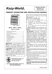
Kozy-<strong>World</strong> VENT-FREE<br />
GAS-FIRED ROOM HEATER<br />
USER'S OPERATION AND INSTALLATION MANUAL<br />
MODELS:KW(N305,P306)-30,000 BTU/HR<br />
AND KW(N205,P206)-20,000 BTU/HR<br />
WARNING:If the information in this manual is not followed exactly, a fire or<br />
explosion may result causing property damage, personal injury, or loss <strong>of</strong> life.<br />
- Do not store or use gasoline or other flammable vapors and liquids in the<br />
vicinity <strong>of</strong> this or any other appliance.<br />
- WHAT TO DO IF YOU SMELL GAS<br />
Do not try to light any appliance.<br />
Do not touch any electrical switch; do not use any phone in your building.<br />
Immediately call your gas supplier from a neighbor's phone. Follow the gas<br />
supplier's instructions.<br />
If you cannot reach your gas supplier, call the fire department.<br />
- Installation and service must be performed by a qualified installer, service agency<br />
or the gas supplier.<br />
- INSTALLER : LEAVE THIS MANUAL WITH THE CONSUMER<br />
- CONSUMER : RETAIN THIS MANUAL FOR FUTURE REFERENCE<br />
<br />
<br />
<br />
…¿<br />
ƒn
CONTENTS<br />
SECTION I-<br />
SECTION II-<br />
SECTION III-<br />
SECTION IV-<br />
SECTION V-<br />
SECTION VI-<br />
SECTION VII-<br />
SECTION VIII-<br />
SECTION IX-<br />
SECTION X-<br />
SECTION XI-<br />
SECTION XII-<br />
SECTION XIII<br />
SECTION XIV-<br />
SECTION XV-<br />
SECTION XVI-<br />
General Safety Instructions<br />
Product Identification<br />
Local Codes/National Fuel Code<br />
Unpacking the Heater Package<br />
Product Features<br />
Fresh Air for Combustion and Ventilation<br />
Installation<br />
Gas Requirements<br />
Leak Checking<br />
Operating the Heater<br />
Inspecting Burner & Pilot Burner Flames<br />
Care And Maintenance<br />
Troubleshooting<br />
Specifications<br />
Accessories<br />
Parts List<br />
Warranty Information<br />
2<br />
3<br />
3<br />
4<br />
4<br />
4<br />
5<br />
9<br />
10<br />
11<br />
14<br />
15<br />
16<br />
18<br />
18<br />
19<br />
Page 1
GENERAL SAFETY INSTRUCTIONS:<br />
Page 2<br />
SAFETY : Accidents are always tragic especially because so many <strong>of</strong> them could<br />
have been prevented with a little care and judgment. There are some basic good<br />
practices we hope you will follow for safe use <strong>of</strong> your gas-fired room heater.<br />
IMPORTANT : Read this user's manual carefully and completely before<br />
trying to assemble, operate, or service this heater. Improper use <strong>of</strong> this heater<br />
can cause serious injury or death from burns, fire, explosion, electrical shock,<br />
and carbon monoxide poisoning.<br />
Early signs <strong>of</strong> carbon monoxide poisoning resemble the flu, with headaches,<br />
dizziness, or nausea. If you have these signs, the heater may not be working<br />
properly. Get fresh air at once! Have heater serviced. Some people are more<br />
affected by carbon monoxide than others. These include pregnant women, people<br />
with heart or lung disease or anemia, those under the influence <strong>of</strong> alcohol, and those<br />
at high altitudes.<br />
Begin by insuring proper installation and servicing. Follow the installation<br />
instructions provided with this product. Have your heater installed by a qualified<br />
technician. Have the installer show you where the gas supply shut <strong>of</strong>f valve is<br />
located so that you know where to shut <strong>of</strong>f the gas to the heater. If you smell gas,<br />
your installer has not done a proper job <strong>of</strong> checking leaks. If the connections are not<br />
perfectly seated or tightened, you may have a leak and therefore a faint gas smell.<br />
Finding a leak is not a DO-IT-YOURSELF procedure. Some leaks can only be<br />
found with the main burner gas on and this must be done by a qualified technician.<br />
PRECAUTIONS:<br />
✑ Never use natural gas in a unit designed for liquefied petroleum gases.<br />
✑ Never use liquefied petroleum gases in a unit designed for natural gas.<br />
✑ Check all joints and connections. To avoid the danger <strong>of</strong> fire, accident or<br />
explosion, never check a potential gas leak with an open flame.<br />
✑ This heater shall not be installed in a bedroom or bathroom.<br />
✑ Never install the heater in any <strong>of</strong> the following locations:<br />
Recreational vehicle<br />
Where curtains, furniture, clothing, or other flammable objects are less than<br />
36 inches from the front, top, or sides <strong>of</strong> the heater<br />
Fireplace<br />
High traffic area<br />
Drafty areas<br />
✑ This heater needs fresh, outside air for ventilation to run properly. This heater<br />
has an oxygen depletion sensor(ODS)pilot light safety system. The ODS shuts<br />
down the heater if not enough fresh air/oxygen content(18%)is available.<br />
✑ Never run heater in confined space. Open a door to an adjoining room to help<br />
ventilate(For air openings, see National Fuel Code).
✑ If heater shuts <strong>of</strong>f, do not relight until you provide fresh, outside air. If heater<br />
keeps shutting <strong>of</strong>f, have it serviced.<br />
✑ Do not run heater where :<br />
Flammable liquids or vapors are used or stored.<br />
Dusty condition exists.<br />
✑ Never place any objects on the heater.<br />
✑ Supervise children when they are in the same room with heater, never<br />
allow them to sit, stand or play on or around the heater.<br />
✑ Make sure grille guard is in place before running heater.<br />
✑ Do not use heater if any part has been under water. Immediately call a qualified<br />
service technician to inspect the room heater and to replace any part <strong>of</strong> the<br />
control system and any gas control which has been under water.<br />
✑ Keep appliance area clear and free from combustible materials, gasoline and<br />
other flammable vapors and liquids.<br />
✑ Turn <strong>of</strong>f heater and let cool before servicing. Only a qualified technician should<br />
service and repair heater.<br />
PRODUCT IDENTIFICATION:<br />
LOCAL CODES<br />
Install and use heater with care. Follow all local codes. In the absence <strong>of</strong><br />
local codes, use the latest edition <strong>of</strong> the National Fuel Gas Code<br />
ANSI Z223.1, also known as NFPA54*<br />
* Available from:<br />
<strong>America</strong>n National Standards Institute, <strong>Inc</strong>.<br />
1430 Broadway<br />
New York, NY 10018<br />
National Fire Protection Association, <strong>Inc</strong>.<br />
Batterymarch Park<br />
Quincy, MA 02269<br />
Page 3
UNPACKING:<br />
1. Remove heater from carton.<br />
2. Remove all protective packaging applied to heater for shipment.<br />
3. Check heater for any shipping damage. If heater is damaged,<br />
promptly inform dealer/distributor where you bought heater.<br />
PRODUCT FEATURES:<br />
Safety Device<br />
This heater has a pilot with an Oxygen Depletion Sensor Shut<strong>of</strong>f System<br />
(ODS).<br />
The ODS pilot is a required feature for vent-free room heaters. The<br />
ODS pilot shuts <strong>of</strong>f the heater if the normal air oxygen content is reduced<br />
to 18%.<br />
Piezo Ignition System<br />
This heater has a piezo ignitor. This system requires no matches,<br />
batteries, or other sources to light heater.<br />
FRESH AIR FOR COMBUSTION AND VENTILATION:<br />
Page 4<br />
WARNING : This heater must have fresh air for proper operation. If not, poor<br />
fuel combustion could result. Read the following instructions to insure proper fresh<br />
air for this and other fuel-burning appliances in your home.<br />
ADEQUATE COMBUSTION/VENTILATION AIR<br />
All spaces in homes fall into one <strong>of</strong> the three following ventilation classifications:<br />
Unusually Tight Construction : The air that leaks around doors and windows<br />
may provide enough fresh air for combustion and ventilation. However, in<br />
buildings <strong>of</strong> unusually tight construction, you must provide additional fresh air.<br />
Unusually Tight Construction is defined as construction where:<br />
-Walls and ceilings exposed to the outside atmosphere have a continuous<br />
water vapor retarder with a rating or one perm or less with openings gasketed or<br />
sealed and<br />
-Weather stripping has been added on openable windows and doors<br />
-Caulking or sealants are applied to areas such as joints around window and<br />
door frames, between sole plates and floors, between wall-ceiling joints,<br />
between wall panels, at penetrations for plumbing, electrical and gas lines, and<br />
at other openings.
Unconfined Space<br />
An unconfined space whose volume is not less than 50 cubic feet per 1,000<br />
BTU/HR <strong>of</strong> the aggregate input rating <strong>of</strong> all appliances installed in that space.<br />
Rooms communicating directly with the space in which the appliances are<br />
installed, though openings not furnished with doors are considered a part <strong>of</strong><br />
the unconfined space.<br />
Confined Space<br />
A confined space whose volume is less than 50 cubic feet for each 1,000<br />
BTU/HR <strong>of</strong> the aggregate input rating <strong>of</strong> all appliances in that space.<br />
WARNING : You must provide additional ventilation air in a confined space.<br />
For proper operation <strong>of</strong> the unit, provide fresh air opening(s) to the room.<br />
Follow the National Fuel Code NFPA 54 / ANSI Z223.1, for required size <strong>of</strong><br />
combustion and ventilation openings.<br />
NOTICE : A qualified service person must install heater. Follow all local codes.<br />
CHECK GAS TYPE : Verify the type <strong>of</strong> gas supply to be used, either natural or<br />
LP(Propane), and make sure the marking on the appliance rating plate agrees with<br />
that <strong>of</strong> the supply gas. The rating plate is located on the side <strong>of</strong> the heater, which<br />
indicates the type <strong>of</strong> gas that heater is orificed for.<br />
ITEMS NEEDED FOR HEATER INSTALLATION: Before installing heater,<br />
make sure you have the items listed below:<br />
Gas piping (check local codes.).<br />
Test gauge connection<br />
Sealant (resistant to LP gases)<br />
Manual shut<strong>of</strong>f valve*<br />
Sediment trap<br />
Ground joint union<br />
Tee joint and pipe wrench<br />
An installer supplied, design-certified manual shut<strong>of</strong>f valve with 1/8" NPT tap<br />
connection.<br />
LP gases installation, also requires an installer supplied, design certified gas pressure<br />
regulator.<br />
LOCATING HEATER:<br />
This heater is designed to be mounted on a wall. Heater can be located on<br />
floor, away from a wall. An optional floor mounting base is needed,<br />
purchase the floor mounting base from your dealer.<br />
WARNING : Never install the heater<br />
in a bedroom or a bathroom<br />
in a recreational vehicle<br />
where curtains, furniture, clothing, or other flammable objects are less<br />
than 36 inches from the front, top, or sides <strong>of</strong> the heater<br />
as a fireplace insert<br />
Page 5
in high traffic areas<br />
in windy or drafty areas<br />
IMPORTANT : Vent-free heaters add moisture to the air. Although this is<br />
beneficial, installing heater in rooms without enough ventilation<br />
may cause mildew formation from too much moisture content.<br />
See National Fuel Code for Fresh Air for Combustion and<br />
Ventilation.<br />
This appliance may be installed in an aftermarket* manufacture<br />
(Mobile) home, where not prohibited by state or local codes.<br />
*Aftermarket : Completion <strong>of</strong> sale, not for purpose<br />
<strong>of</strong> resale, from the manufacturer.<br />
This appliance is only for use with the type <strong>of</strong> gas indicated on the<br />
rating plate. This appliance is not convertible for use with other gases.<br />
CAUTION :<br />
If you install the heater in a home garage:<br />
Heater must be at least 18 inches above floor.<br />
Locate heater where moving vehicle will not hit it.<br />
Preparing For Installation<br />
Select a location for the heater that will provide maximum exposure <strong>of</strong> the radiant<br />
surface to the room, but will not be subjected to accidental contact.<br />
Adequate clearance must be available around the air opening. See Figures 1 & 2<br />
for clearances that must be maintained to the side walls, floor and horizontal<br />
surface surrounding the heater.<br />
Figure 1 Figure 2<br />
Attaching Mounting Brackets To Wall<br />
Page 6<br />
Note: Wall anchors, mounting screws, and spacers are in hardware package.<br />
The hardware package is provided with heater
1. Install mounting brackets on wall as shown in Figure 2. Use enclosed “paper<br />
template” for proper location <strong>of</strong> holes. It may be necessary to use plastic or lead<br />
anchors for plaster walls.<br />
2. Drill holes at marked locations using 9/64"drill bit.<br />
3. Insert mounting screws through bracket and into wall studs.<br />
4. Tighten screws until mounting bracket is firmly fastened to wall studs.<br />
Attaching to wall anchor method<br />
For attaching mounting bracket to hollow walls(wall areas between studs) or solid<br />
walls (concrete or masonry):<br />
1. Drill holes at marked locations using 5/16" drill bit. For solid walls (concrete or<br />
masonry), drill at least 1 inch deep.<br />
2. Insert the plastic anchor as shown in Figure 3 below:<br />
Figure 3<br />
3. Tap anchor flush to wall as shown in Fig.4<br />
Figure 4<br />
4. Insert mounting screws through each bracket and into wall anchors.<br />
5. Tighten screws until mounting bracket is firmly fastened to wall.<br />
Installing Bottom Mounting Screws<br />
1. Locate two bottom mounting holes. These holes are near bottom on back<br />
panel <strong>of</strong> heater (See Figure 5.).<br />
2. Mark screw locations on wall.<br />
3. Remove heater from mounting bracket.<br />
4. If installing bottom mounting screws into hollow or solid wall, install wall<br />
anchors. Follow steps 1 through 4 under, "Attaching To Wall Anchor Method",<br />
page 7. If installing bottom mounting screw into wall stud, drill holes at marked<br />
locations using 9/64 drill bit.<br />
5. Replace heater onto mounting bracket.<br />
6. Place spacers between bottom mounting holes and wall anchor or drilled hole.<br />
7. Hold spacer in place with one hand. With other hand, insert mounting screw<br />
through bottom mounting hole and spacer. Place tip <strong>of</strong> screw in opening <strong>of</strong> wall<br />
Page 7
anchor or drilled hole.<br />
8. Tighten both screws until heater is firmly secured to wall. Do not over tighten.<br />
Figure 5<br />
1. Clearance requirements from surface <strong>of</strong> carpeting, tile or other combustible<br />
material (See Figure 1.).<br />
Wall Mounted & Floor Mounted With Base Provided<br />
Rear<br />
Sides<br />
Top<br />
Floor<br />
0 <strong>Inc</strong>hes<br />
6 <strong>Inc</strong>hes<br />
36 <strong>Inc</strong>hes<br />
2 <strong>Inc</strong>hes<br />
Figure 6<br />
NOTICE:<br />
Maintain the minimum clearances shown in Figure 1, but you can provide greater<br />
clearances from floor, ceiling and adjoining wall.<br />
2. After mounting brackets are installed, hang heater on mounting brackets in holes<br />
provided at the rear <strong>of</strong> heater (See Figure 7.).<br />
Page 8
Figure 7<br />
3. Installation and repair should be done by a qualified service person. The room<br />
heater should be inspected before use and at least annually by a pr<strong>of</strong>essional<br />
service person. More frequent cleaning may be required due to excessive lint from<br />
carpeting and other materials. It is imperative that the control compartments,<br />
burners and circulating air passageways <strong>of</strong> the heater be kept clean.<br />
CONNECTING TO GAS SUPPLY :<br />
WARNING : Never connect an unregulated gas line to the heater.<br />
An installer supplied, design certified gas pressure regulator must be installed to<br />
bring the gas supply pressure down to 14 inches <strong>of</strong> water column.<br />
IMPORTANT : Check gas line pressure before connecting heater to gas line.<br />
Gas line pressure must not be higher than 14 inches <strong>of</strong> water. If gas line pressure is<br />
higher, heater gas pressure regulator damage could occur.<br />
CAUTION : Use only new, black iron or steel pipe and internally-tinned copper<br />
tubing may be used in certain areas. Check your local codes. Use pipe <strong>of</strong> large<br />
enough diameter to allow proper gas volume to heater. If pipe is too small, undue<br />
pressure loss will occur.<br />
Typical Gas Supply Pipe Diameters<br />
20,000 BTU/HR Model 3/8" or greater<br />
30,000 BTU/HR Model 3/8" or greater<br />
CAUTION:<br />
Use pipe joint sealant that is resistant to liquefied petroleum gases.<br />
Install sediment trap in supply line as shown in Figure 8 Gas Connection. Locate<br />
sediment trap where it is within reach for cleaning. Locate sediment trap where<br />
trapped matter is not likely to freeze. A sediment trap traps moisture and<br />
contaminants. This keeps them from going into heater controls. If sediment trap<br />
is not installed or is installed wrong, heater may not run properly.<br />
Page 9
Figure 8<br />
LEAK CHECKING:<br />
GENERAL : Although all gas connections on the heater are leak tested at the<br />
factory prior to shipment, a complete gas tightness check must be performed at the<br />
installation site due to possible mishandling in shipment, or excessive pressure<br />
unknowingly being applied to the appliance. Periodically check the whole system for<br />
leaks, or immediately check if the smell <strong>of</strong> gas is detected.<br />
BEFORE TESTING<br />
Do not smoke while leak testing. Extinguish all open flames.<br />
Make a soap solution <strong>of</strong> one part liquid detergent and one part water. You will need<br />
a spray bottle, brush or a piece <strong>of</strong> rag to apply the solution to the fittings.<br />
For LP units, check with a full cylinder.<br />
CAUTION : NEVER LEAK TEST WITH AN OPEN FLAME<br />
PRESSURE TESTING-GAS SUPPLY PIPING SYSTEM<br />
The appliance and its individual shut<strong>of</strong>f valve must be disconnected from the gas<br />
supply piping system during any pressure testing <strong>of</strong> that system at test pressures<br />
in excess <strong>of</strong> 1/2 psig.<br />
The appliance must be isolated from the gas supply piping system by closing its<br />
individual manual shut<strong>of</strong>f valve during any pressure testing <strong>of</strong> the gas supply<br />
piping system at test pressures equal to less than 1/2 psig.<br />
Page 10
LEAK TESTING HEATER GAS CONNECTIONS:<br />
1. Open manual shut<strong>of</strong>f valve.<br />
2. Open main gas valve located near gas meter.<br />
3. Make sure control knob <strong>of</strong> heater is in the OFF position.<br />
4. Check all joints from manual gas valve up to gas control and including the<br />
manifold assembly. Apply the soap solution around the connections, valve and<br />
tubing. Soap bubbles will appear where a leak is present.<br />
5. If a leak is present, immediately turn <strong>of</strong>f gas supply, tighten any leaky fittings, turn<br />
gas on and recheck.<br />
6. To check burner and safety valve, the burner must be lit (See operating<br />
Instructions.). Check the rest <strong>of</strong> the connections for leaks.<br />
7. Turn <strong>of</strong>f the heater (See Instructions.).<br />
NOTE:<br />
Never use an open flame to check for a leak. Apply a mixture <strong>of</strong> liquid soap<br />
and water to all joints. Bubbles forming show a leak. Correct all leaks at<br />
once.<br />
OPERATING HEATER:<br />
WARNING:<br />
Before lighting, smell all around the appliance area for gas. Be sure to smell<br />
next to the floor because some gas is heavier than air and will settle on the<br />
floor. If you smell gas, follow the Safety Instructions on the front page and<br />
under Section I.<br />
Page 11
Use only your hand to push in or turn the gas control knob. Never use tools.<br />
If the knob will not push in or turn by hand, don’t try to repair it, call qualified<br />
service technician or gas supplier. Force or attempted repair may result in a fire<br />
or explosion.<br />
Do not use this appliance if any part has been under water. Immediately call<br />
a qualified service technician to inspect the appliance and replace any part <strong>of</strong><br />
the control system and any gas control component which has been under water.<br />
LIGHTING INSTRUCTIONS:<br />
1. Read the aforementioned safety information.<br />
2. Make sure manual shut<strong>of</strong>f valve is fully open.<br />
3. Push in gas control knob slightly and turn clockwise to the OFF<br />
position.<br />
4. Wait five minutes to clear any gas. Then smell for gas, including near the<br />
floor. If you smell gas, follow the safety information on the front page. If you<br />
don’t smell gas, go to the next step.<br />
5. Push in gas control knob slightly and turn counterclockwise to<br />
"PILOT/IGN" and depress for five(5) seconds.<br />
NOTE : The first time that the heater is operated after connecting the gas<br />
supply, the control knob should be depressed for about thirty(30) seconds. This<br />
will allow, air to bleed from the gas system.<br />
6. Release control knob pressure and turn clockwise to "OFF".<br />
7. Depress control knob while OFF, then turn back to PILOT/IGN.<br />
This should cause the spark from the piezo ignitor to light the pilot gas.<br />
Keep control knob depressed for ten(10) seconds before releasing. If pilot does<br />
not light, repeat steps 5, 6 and 7 or use a match.<br />
8. To select the heating level desired, partially press down the control slightly and<br />
rotate counterclockwise .<br />
Release the downward Pressure on the knob while continuing to turn until the<br />
knob locks at the desired setting position. Do not operate between the locked<br />
position.<br />
CONTROL<br />
KNOB<br />
Page 12
Note : If pilot goes out, repeat steps 3 through 7.<br />
TO TURN OFF GAS TO HEATER<br />
Shutting Off Heater<br />
1. Turn control knob clockwise to the OFF position.<br />
Shutting Off Burner Only(pilot stays lit)<br />
1. Turn control knob clockwise to the PILOT position.<br />
CAUTION<br />
Do not try to adjust heating levels by using the manual shut<strong>of</strong>f valve.<br />
Page 13
Note : The thermostat sensing bulb measures the temperature <strong>of</strong> air near the<br />
heater cabinet. This may not always agree with room temperature (depending<br />
on housing construction, installation location, room size etc.). Frequent use <strong>of</strong><br />
your heater will let you determine your own comfort levels.<br />
MANUAL LIGHTING INSTRUCTIONS<br />
1. Remove lower front panel.<br />
2. Follow steps 1 through 4 as stated under Lighting Instructions.<br />
3. Press and turn control knob counterclockwise to the PILOT position.<br />
4. With control knob pressed in, strike match, hold match to pilot until pilot lights.<br />
5. Keep control knob pressed in for 30 seconds after lighting pilot. After 30<br />
seconds, release control knob.<br />
6. Replace lower front panel.<br />
INSPECTING MAIN BURNER AND PILOT BURNER<br />
Pilot Flame Pattern<br />
The following figures show a correct and incorrect flame patterns. The incorrect<br />
flame is not touching the thermocouple. This will cause a nuisance shut down.<br />
CORRECT<br />
INCORRECT<br />
If pilot flame pattern is incorrect as shown above, turn heater <strong>of</strong>f and refer to<br />
troubleshooting guide.<br />
Burner Flame Pattern<br />
Correct and incorrect flame patterns are shown as below. The incorrect burner<br />
flame pattern shows yellow tipping <strong>of</strong> the flame.<br />
Page 14
WARNING :<br />
If yellow tipping occurs, your heater could produce increased levels <strong>of</strong> carbon<br />
monoxide. If burner flame pattern shows yellow tipping, follow instructions at<br />
bottom <strong>of</strong> this page.<br />
NOTICE : Do not mistake orange flames with yellow tipping. Dirt or other<br />
particles etc. enter the heater and cause transient patches <strong>of</strong> orange flame.<br />
CARE AND MAINTENANCE :<br />
Dust, list or debris may affect heater performance. The heater draws air into it during normal<br />
operation. In the process dust, lint or debris will be drawn into the heater and spider webs can<br />
build up during <strong>of</strong>f season. Keep burner, gas control and combustion and circulating air<br />
passageways clean. Inspect or have these areas inspected annually at the beginning <strong>of</strong> the<br />
heating season by a qualified service person. Room heater may require frequent cleaning due<br />
to excessive lint or debris depending upon the surroundings.<br />
BEFORE CLEANING - Ensure the gas supply is <strong>of</strong>f and the gas control knob<br />
is in the <strong>of</strong>f position. Make sure the heater is cool.<br />
WARNING:DANGER OF BODILY INJURY<br />
If fan assembly accessory is used, turn <strong>of</strong>f power supply at disconnect<br />
switch or service panel before removing any access panels from heater.<br />
BURNER AND ODS PILOT CLEANING - Clean the exterior with s<strong>of</strong>t bristle<br />
brush, vacuum cleaner pressurized air. Never use a wooden toothpick as it may<br />
break <strong>of</strong>f and clog the ODS pilot or main burner port.<br />
Use a flashlight to inspect the main burner inlet to ensure it is not blocked. If<br />
obstruction can be seen, use a metal wire coat hanger that has been straightened<br />
out.<br />
In order to clean ODS pilot orifice, use pressurized air to blow dust out.<br />
Sometimes blowing air backwards through the pilot will get rid <strong>of</strong> the<br />
accumulated dirt. If that does not work, blow out any dust through primary air<br />
openings <strong>of</strong> pilot assemblies(Daemyeong has two openings; one beneath the<br />
bimetal strip and the second one opposite from bimetal strip. Use the one wide<br />
open, do not try to lift the bimetal.).<br />
AIR PASSAGEWAYS AND UNIT CASINGS - Use a vacuum cleaner or<br />
pressurized air to clean the combustion and circulating air passageways and<br />
dampened cloth to clean the cabinet/casing.<br />
Page 15
TROUBLESHOOTING:<br />
PROBLEM POSSIBLE CAUSE WHAT TO DO<br />
When control knob<br />
is pressed in and<br />
turned counterclockwise<br />
to ignition, there is no<br />
spark at ODS pilot.<br />
1. Ignitor electrode positioned<br />
wrong.<br />
2. Ignitor electrode broken.<br />
3. Ignitor cable pinched or<br />
broken.<br />
4. Ignitor cable not connected<br />
to ignitor electrode.<br />
1. Replace Ignitor<br />
electrode.<br />
2. Replace electrode.<br />
3. Free ignitor cable, if<br />
damaged replace it.<br />
4. Connect cable to<br />
electrode.<br />
When control knob<br />
is pressed in and<br />
turned counterclockwise<br />
to ignition/pilot<br />
position, there is spark<br />
but no ignition.<br />
1. Gas supply turned <strong>of</strong>f.<br />
2. Control knob not in pilot<br />
position.<br />
3. Control knob not pressed<br />
in while in pilot position.<br />
4. ODS pilot is clogged.<br />
5. Air in gas Lines.<br />
1. Turn on gas supply.<br />
2. Turn control knob to<br />
pilot position.<br />
3. Press in control while<br />
in pilot position.<br />
4. Call a qualified person<br />
5. Purge gas lines and<br />
repeat ignition<br />
operation.<br />
ODS pilot lights but<br />
flame goes out when<br />
control knob is<br />
released.<br />
1. Control knob not pressed<br />
long enough.<br />
2. Safety interlock is triggered.<br />
3. Pilot flame not touching<br />
the thermocouple. Problem<br />
could be result <strong>of</strong> one or<br />
both <strong>of</strong> the following:<br />
Partially clogged ODS pilot<br />
orifice.<br />
Low gas pressure.<br />
4. Thermocouple damaged.<br />
5. Thermocouple connection<br />
loose at gas control valve.<br />
6. Gas control valve damaged.<br />
1. After ODS pilot lights,<br />
keep control knob<br />
pressed in approx. 30<br />
sec.<br />
2. Wait a minute, repeat<br />
ignition operation.<br />
3. Contact your gas<br />
company or gas<br />
supplier or qualified<br />
service person.<br />
4. Replace thermocouple.<br />
5. Hand tight until snug<br />
then tighten 1/4 turn<br />
with a wrench.<br />
6. Replace gas control.<br />
Burner does not light<br />
after ODS pilot is lit<br />
1. Burner orifice clogged.<br />
2. Gas supply pressure is very<br />
low.<br />
1. Clean burner orifice.<br />
2. Contact the Gas Co.<br />
Page 16<br />
Delayed ignition<br />
1. Main burner carry over ports<br />
clogged.<br />
2. Gas supply pressure is very<br />
low.<br />
1. Clean main burner ports.<br />
2. Call your gas supplier.
PROBLEM POSSIBLE CAUSE WHAT TO DO<br />
Burner backfiring<br />
during operation<br />
Yellow flames during<br />
burner operation<br />
Slight smoke and odor<br />
during initial operation<br />
Heater produces a<br />
whistling noise when<br />
burner is lit.<br />
Heater produces a<br />
clicking noise just<br />
after burner is lit or<br />
turned <strong>of</strong>f.<br />
Gas odor even when<br />
control knob is in OFF<br />
position.<br />
Gas odor during<br />
combustion<br />
Heater shuts <strong>of</strong>f<br />
on ODS<br />
1. Burner orifice is clogged.<br />
2. Burner ports damaged.<br />
1. Not enough air<br />
1. Residues from<br />
manufacturing processes.<br />
1. Air passageways blocked.<br />
2. Air in gas line<br />
1. Metal expanding and<br />
contracting, respectively.<br />
1. Gas leaks. See front page<br />
Warnings.<br />
2. Gas control defective<br />
1. Foreign matter in gas or on<br />
burner ports.<br />
2. Heater burning vapors from<br />
paint, impurities in air.<br />
3. Gas leaks. See front page<br />
Warnings.<br />
1. Not enough fresh air is<br />
available.<br />
2. Low gas pressure<br />
3. ODS pilot partially clogged.<br />
1. Clean burner orifice.<br />
2. Replace burner.<br />
1. Check air passageways<br />
and burner for dirt and<br />
debris(see care &<br />
maintenance.).<br />
1. Will stop after a few<br />
hours <strong>of</strong> operation.<br />
1. Check minimum<br />
installation clearances<br />
and air passageways for<br />
debris.<br />
2. Operate burner until the<br />
air is completely purged.<br />
1. This is common with<br />
heaters. If noise is<br />
excessive, contact a<br />
qualified person.<br />
1. Locate and correct leaks<br />
immediately.<br />
2. Replace gas control<br />
1. Check gas passage way<br />
and burner.<br />
2. Ventilate room, stop<br />
storing and using odor<br />
causing products near<br />
the heater.<br />
3. Locate and correct<br />
leaks immediately.<br />
1. Open window.<br />
2. Contact your gas<br />
company.<br />
3. Clean the pilot.<br />
Page 17
SPECIFICATIONS:<br />
MODELS<br />
KW(N305,P306)<br />
N305<br />
P306<br />
KW(N205,P206)<br />
N205<br />
P206<br />
INPUT RATING<br />
(BTU/HR,Variable) 30,000/17,400<br />
30,000/17,400 20,000/11,700 20,000/11,700<br />
TYPE OF GAS<br />
NATURAL LP GASES NATURAL LP GASES<br />
REGULATOR<br />
PRESSURE<br />
SETTING<br />
3.0W.C.<br />
8.0W.C.<br />
3.0W.C.<br />
8.0W.C.<br />
INLET GAS SUPPLY<br />
PRESSURE:<br />
MAXIMUM<br />
MINIMUM<br />
10.5W.C.<br />
4.0W.C.<br />
14.0W.C.<br />
11.0W.C.<br />
10.5W.C.<br />
4.0W.C.<br />
14.0W.C.<br />
11.0W.C.<br />
SIZE OF HEATER<br />
(HWD)<br />
23.825.78<br />
23.818.38<br />
WEIGHT<br />
30LBS<br />
22LBS<br />
NOTE : For altitudes above 2,000 feet, reduce the input rating(BTU/HR)4% for<br />
each 1,000 feet above sea level.<br />
"DO NOT USE THIS HEATER AT AN ELEVATION ABOVE 4,500 FEET"<br />
OPTIONAL ACCESSORIES : Purchase these heater accessories from your local<br />
distributors/dealers. If they can not furnish these items, call <strong>World</strong> <strong>Marketing</strong> <strong>of</strong> <strong>America</strong>, <strong>Inc</strong>.<br />
@1-814-643-2299 for more detailed information.<br />
FLOOR MOUNTING BASE : NO. 20-5231 may be used for MODEL(KWN 305, KWP 306).<br />
No. 20-5221 may be used for MODEL(KWN 205, KWP 206).<br />
Page 18
PARTS LIST<br />
Page 19
PARTS LIST<br />
ITEM<br />
NO.<br />
DESCRIPTION<br />
PART NO. FOR<br />
KW(N305,P306) KW(N205,P206)<br />
1.<br />
2.<br />
3.<br />
4.<br />
5.<br />
6.<br />
7.<br />
8.<br />
9.<br />
10.<br />
11.<br />
12.<br />
13.<br />
14.<br />
15.<br />
16.<br />
17.<br />
18.<br />
19.<br />
20.<br />
21.<br />
22.<br />
23.<br />
23-1.<br />
23-.2<br />
24.<br />
25.<br />
26.<br />
27.<br />
Unit Casing Assembly<br />
Main Burner Assembly<br />
Firebox Assembly<br />
Glass Panel<br />
Glass Holder-U<br />
Glass Holder-L<br />
Grille Guard<br />
Lower Panel<br />
Valve Bracket<br />
Gas Control (Daemyeong Korea)<br />
Burner Support -L(R)<br />
Cover Heat<br />
Pressure Regulator(3/8") [NG:3", LP:8"]<br />
Inlet Tubing Assembly<br />
Outlet Tubing Assembly<br />
Nozzle Holder<br />
Nozzle Holder Nut<br />
Nozzle<br />
Wall Mounting Bracket-L(R)<br />
Screw<br />
Valve Knob<br />
ODS Pilot Tubing(3/16") Assembly<br />
ODS Pilot Assembly (Daemyeong Korea)<br />
Electrode<br />
Thermocouple<br />
ODS Mounting Screw<br />
Regulator Fix Screw<br />
Wall Mounting Screw<br />
Screw<br />
2A0052<br />
2A0079<br />
3A1033a<br />
3A1018a<br />
3A1011a<br />
3A1012a<br />
1A0040<br />
1A1013<br />
3A0048<br />
DMV100PD/C<br />
2A0094<br />
1A1026<br />
DR40M3KN/L<br />
-<br />
-<br />
4A1027<br />
4A1028<br />
4A1029<br />
3A1010<br />
-<br />
3A0089<br />
2A1034<br />
DS98PN/L02<br />
-<br />
-<br />
-<br />
-<br />
-<br />
-<br />
2A0053<br />
2A0080<br />
3A1033b<br />
3A1018b<br />
3A1011b<br />
3A1012b<br />
1A0041<br />
1A1023<br />
3A0048<br />
DMV100PB/A<br />
2A0094<br />
1A1027<br />
DR40M2KN/L<br />
-<br />
-<br />
4A1027<br />
4A1028<br />
4A1029<br />
3A1010<br />
-<br />
3A0089<br />
2A1034<br />
DS98PN/L02<br />
-<br />
-<br />
-<br />
-<br />
-<br />
-<br />
Page 20
LIMITED WARRANTY:<br />
This limited warranty is extended to the original retail purchaser <strong>of</strong> this Kozy-<strong>World</strong> Heater and warrants against<br />
any defect in materials in workmanship for a period <strong>of</strong> two (2) years from the date <strong>of</strong> retail sale. <strong>World</strong> <strong>Marketing</strong> <strong>of</strong><br />
<strong>America</strong>, <strong>Inc</strong>., at it's option, will either provide replacement parts or replace or repair the unit, when properly<br />
returned to the retailer, within two (2) years <strong>of</strong> retail purchase. (Shipping costs, installation or removal <strong>of</strong> the unit<br />
and any other associated field labor costs are the responsibility <strong>of</strong> the purchaser.)<br />
DUTIES OF THE OWNER:<br />
This heating appliance must be installed and tested by a qualified individual and operated in accordance with the<br />
written instructions fumished with this heater. This warranty shall not excuse the owner from properly<br />
maintaining this heater in accordance with the written instructions furnished with this heater. A bill <strong>of</strong> sale,<br />
canceled check or payment record must be kept to verify purchase date and establish warranty period. Original<br />
carton should be kept in case <strong>of</strong> warranty return <strong>of</strong> unit.<br />
WHAT IS NOT COVERED:<br />
Travel, diagnostic cost, service labor, labor to repair the defective appliance and freight charges on warranty parts<br />
or heaters to and from the factory shall be the responsibility <strong>of</strong> the owner.<br />
This warranty does not imply or assume any responsibility for consequential damages that may result from the use,<br />
misuse, improper installation or the lack <strong>of</strong> routine maintenance <strong>of</strong> this heating appliance. A cleaning fee and the<br />
cost <strong>of</strong> parts may be charged for appliance failures resulting from the lack <strong>of</strong> maintenance. This warranty does<br />
not cover claims which do not involve defective workmanship or matenals. FAILURE TO PERFORM GENERAL<br />
MAINTENANCE<br />
(INCLUDING CLEANING) WILL VOID THIS WARRANTY.<br />
THIS LIMITED WARRANTY IS GIVEN TO THE PURCHASER IN LIEU OF ALL OTHER WARRANTIES,<br />
EXPRESSED OR IMPLIED, INCLUDING BUT NOT LIMITED TO THE WARRANTIES OF MERCHANT ABILITY<br />
OF FITNESS FOR A PARTICULAR PURPOSE. THE REMEDY PROVIDED IN THIS WARRANTY IS<br />
EXCLUSIVE AND IS GRANTED IN LIEU OF ALL OTHER REMEDIES. IN NO EVENT WILL WORLD<br />
MARKETING OF AMERICA BE LIABLE FOR INCIDENTAL OR CONSEQUENTIAL DAMAGES.<br />
Some states do not allow limitations on how long an implied warranty lasts, so the above limitation may not<br />
apply to you. Some states do not allow the exclusion or limitation <strong>of</strong> incidental or consequential damages so the<br />
above limitation or exclusion may not apply to you.<br />
CLAIMS HANDLED AS FOLLOWS:<br />
1. Contact your retailer and explain your problem.<br />
2. If the retailer cannot resolve the problem, write out. Consumer Warranty Dept. detailing the heater model, the<br />
problem, copy <strong>of</strong> the sales receipt or date <strong>of</strong> purchase. Send letter to the attention <strong>of</strong> "Warranty Claims<br />
Administrator."<br />
3. A representative <strong>of</strong> Kozy-<strong>World</strong> will contact you. DO NOT RETURN THE HEATER TO WORLD<br />
MARKETING OF AMERICA, INC.<br />
This warranty gives you specific legal rights and you may also have other rights which vary from state to state.<br />
DO NOT RETURN THE HEATER TO WORLD MARKETING OF AMERICA, INC. YOU WILL BE CONTACTED<br />
BY OUR REPRESENTATIVE.<br />
TO REGISTER THE WARRANTY ON YOUR HEATER, PLEASE FILL OUT THIS CARD<br />
COMPLETELY AND MAIL WITHIN 14 DAYS FROM DATE OF PURCHASE.<br />
NAME: PHONE:( )<br />
ADDRESS:<br />
CITY: STATE: ZIP:<br />
MODEL: SERIAL #. DATE PURCHASED:<br />
DEALER PURCHASED FORM:<br />
TYPE OF STORE:<br />
CITY & STATE WHERE PURCHASED:<br />
PRICE PAID:<br />
Please Take a Minute To Give Us Your Answers To The Following Questions.<br />
All Responses Are Used Solely For Market Research And Are Held In Strict Confidence.<br />
Do you own any other portable heaters Yes No<br />
If you do: How many What Brands Satisfied<br />
Please indicate your age group: Under 25, 32-34, 35-44, 45-54, 55-64, 65 or older<br />
How do you intend to use your new heater Emergency Heat, Extra Heat, Primary Heat<br />
Were did you hear about this heater<br />
What made you select this heater Price, Store Display, Salesperson, Recommendation,<br />
Radio ad, Newspaper ad, Other (Please Specify)<br />
What is your occupation<br />
What is your income bracket A. Under $15,000 B. $15-30,000 C. $30-45,000<br />
D. $45-60,000 E. Over $60,000<br />
Do you own or rent your home<br />
Would you recommend this heater to a friend<br />
THANK YOU FOR COMPLETING THIS FORM!
SOLVING COMMON PROBLEMS<br />
The 3 most common problems associated with any gas heater are gas leaks, wrong gas pressure and dirt.<br />
Do Not Use Your Heater Without Checking For Leaks! Leaks can occur during shipment and installation. A simple<br />
solution <strong>of</strong> soap and water dabbed on the fittings will bubble if a gas leak is present. Do not take short cuts!<br />
Wrong Gas Pressure! Too much gas pressure may severely damage your heater. Too little gas pressure and<br />
your heater will not burn correctly. If your installer can not check gas pressure, find one who can or call your gas<br />
supplier. Do not take shortcuts!<br />
Dust & Dirt! This heater does require some cleaning. If the pilot light will not stay lit or if one brick is not as bright as<br />
another, your heater is probably due for a good cleaning.<br />
Replacement <strong>of</strong> the thermocouple or pilot assembly is generally not needed. Review Heater Maintenance on<br />
page 15 <strong>of</strong> the owners manual.<br />
While we want every one to be completely satisfied with their purchase it is impossible to cover problems<br />
occurring form improper installation or a lack <strong>of</strong> maintenance.<br />
Kozy-<strong>World</strong> Warranty Registration<br />
IMPORTANT: We urge you to fill out your warranty registration card within ten(10) days <strong>of</strong> date <strong>of</strong> installation,<br />
complete with the entire serial number which can be found on the rating plate. Retain this portion <strong>of</strong> the card for<br />
your records.<br />
<strong>World</strong> <strong>Marketing</strong> <strong>of</strong> <strong>America</strong>, <strong>Inc</strong>.<br />
PO Box 192, Route 22 West<br />
Mill Creek, PA 17060-0192<br />
Tel) 1-814-643-2299<br />
www.worldmkting.com<br />
SAVE THIS CARD!<br />
Place<br />
Postage<br />
Stamp<br />
Here<br />
<strong>World</strong> <strong>Marketing</strong> <strong>of</strong> <strong>America</strong>, <strong>Inc</strong>.<br />
PO Box 192, Route 22 West<br />
Mill Creek, PA 17060-0192