RS-2000 Manual - Winegard
RS-2000 Manual - Winegard
RS-2000 Manual - Winegard

You also want an ePaper? Increase the reach of your titles
YUMPU automatically turns print PDFs into web optimized ePapers that Google loves.
TM<br />
ROADSTAR<br />
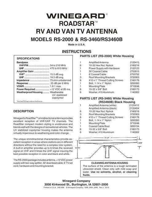
RV AND VAN TV ANTENNA<br />
MODELS <strong>RS</strong>-<strong>2000</strong> & <strong>RS</strong>-3460/<strong>RS</strong>3460B<br />
SPECIFICATIONS<br />
Bandpass<br />
VHF/FM .............................. 54 to 216 MHz<br />
UHF .................................... 470 to 810 MHz<br />
Amplifier Gain ......................<br />
VHF* .................................. 15.5 dB avg.<br />
UHF .................................... 19.5 dB avg.<br />
Impedance ............................ 75 ohm unbalanced<br />
Response .............................. .25 dB per 6 MHz<br />
VSWR .................................... 1.8:1 max.<br />
Power Required .................... +12 VDC at 85 ma<br />
Weatherproof Housing ......... Weatherable<br />
UV stabilized<br />
copolymer<br />
*Has fixed FM trap to reduce interference.<br />
DESCRIPTION<br />
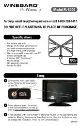
<strong>Winegard</strong>'s RoadStar TM omnidirectional antenna provides<br />
excellent reception of VHF/UHF TV channels. The<br />
RoadStar compact modern styling is unobtrusive and<br />
blends well with the designs of recreational vehicles. The<br />
UV stabilized copolymer housing makes the antenna<br />
virtually impervious to weathering and color change.<br />
The unique omnidirectional characteristics provide excellent<br />
reception in areas where stations are in different<br />
directions without the need for a complex rotor system.<br />
A built-in amplifier provides up to 6 times the received<br />
signal on VHF and 9 times the UHF signal insuring the<br />
best possible reception in color and black and white.<br />
WINEGARD ®<br />
Made in U.S.A.<br />
INSTRUCTIONS<br />
PARTS LIST (<strong>RS</strong>-<strong>2000</strong>) White Housing<br />
1 Amplified Antenna 2120415<br />
6 10-32 Hex Nut, Nylock 2160216<br />
1 Power Supply with Hardware 2120123<br />
1 30' Coaxial Cable 2753015<br />
1 6' Coaxial Cable 2753752<br />
3 Roof Mounting Brackets 3720303<br />
6 #10 x 1" Thread Cutting Screws 2160178<br />
1 Bolt, 1-14 x 1" Nylon 3200350<br />
1 Mounting Plate 3710248<br />
6 10-32 x 5/8" Bolt 2160173<br />
6 Washer, #10 Aluminum 1140302<br />
PARTS LIST (<strong>RS</strong>-3460) White Housing<br />
(<strong>RS</strong>3460B) Black Housing<br />
1 Amplified Antenna (white) 2120415<br />
Amplified Antenna (black) 2120404<br />
6 10-32 Hex Nut, Nylock 2160216<br />
3 Roof Mounting Brackets 3720303<br />
6 #10 x 1" Thread Cutting Screws 2160178<br />
1 Bolt, 1-14 x 1" Nylon 3200350<br />
1 Mounting Plate 3710248<br />
1 Coaxial Cable Boot 3200154<br />
6 10-32 x 5/8" Bolt 2160173<br />
6 Washer, #10 Aluminum 1140302<br />
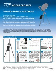
The <strong>RS</strong>-<strong>2000</strong> package includes antenna, +12 VDC power<br />
supply with two-way splitter, 30' downlead cable, 6' TV set<br />
cord, hardware and mounting bracket.<br />
CLEANING ANTENNA HOUSING<br />
The surface of the antenna is a tough laminated<br />
ultraviolet shield. Clean only with mild soap and<br />
water. Use no solvents, alcohol, or cleaning<br />
fluids.<br />
<strong>Winegard</strong> Company<br />
3000 Kirkwood St., Burlington, IA 52601-<strong>2000</strong><br />
Printed in U.S.A. 2451806 © <strong>Winegard</strong> Company, 1998, 2004, 2006 Rev.3 10/10
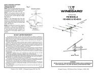
ANTENNA MOUNTING INSTRUCTIONS<br />
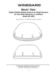
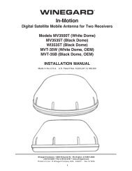
STEP 1. Assemble mounting brackets onto mounting<br />
plate. Insert 10-32 x 5/8" bolts through mounting plate<br />
and mounting brackets. See Figure 1. Attach #10 x 9/16<br />
x 1/6 washers and 10-32 locking nuts. Tighten securely.<br />
NOTE: Holes for mounting brackets are at corners of<br />
19-5/8" triangle. We recommend you make a template<br />
from 19-5/8" triangular piece of cardboard. Try to<br />
locate holes on roof rafters on other solid members<br />
inside roof. See Figure 5.<br />
FIGURE 1<br />
STEP 2. Place assembled mount on bottom of antenna<br />
housing and thread in 1" nylon bolt. Spin the assembled<br />
mount to tighten securely.<br />
FIGURE 5<br />
19-5/8" 19-5/8"<br />
19-5/8"<br />
FIGURE 2<br />
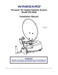
STEP 3. Attach end of coaxial downlead cable with boot<br />
to jack on bottom of antenna and slide boot up over boot<br />
collar. See Figure 3.<br />
LOCATE HOLES OVER<br />
RAFTE<strong>RS</strong> OR OTHER<br />
SUPPORTS IN ROOF<br />
ROOF MOUNTING<br />
BRACKETS<br />
APPLY APPROVED NON-HARDENING<br />
CAULKING COMPOUND UNDER<br />
EACH BRACKET<br />
#10 x 1" THREAD<br />
CUTTING SCREWS<br />
FIGURE 3<br />
STEP 4. Select location for antenna on roof of vehicle.<br />
Try to position antenna about 24" from edge of vehicle<br />
roof, convenient to downlead entry point and as far away<br />
as possible from roof mounted equipment such as air<br />
conditioners or roof vents. See Figure 4.<br />
FIGURE 4<br />
or no reception.<br />
2<br />
FIGURE 6<br />
STEP 5. Drill six 1/8" pilot holes as shown in Figure 6.<br />
Apply approved sealant for your type of roof around holes<br />
under each bracket. Attach antenna to roof with #10 x 1"<br />
thread cutting screws.<br />
STEP 6. The power supply/wall outlet assembly may be<br />
flush mounted in most standard electrical boxes. To flush<br />
mount cut a hole in wall to fit the box. Run 2 #12 wires<br />
between wall outlet and +12 VDC source and route<br />
downlead cable to this location. Install cable between set<br />
2 outlet and power supply SET 2 jack at this time.<br />
See Figure 7.<br />
WARNING: DO NOT CONNECT +12 VDC SOURCE TO<br />
POWER SUPPLY AT THIS TIME. POWER SUPPLY<br />
MAY SHORT, IF +12 VDC SOURCE IS CONNECTED.
STEP 7. Install connectors on downlead and set 2 cable<br />
as shown on page 4. Attach antenna downlead cable to<br />
jack on power supply marked “ANT”. See Figure 7.<br />
FIGURE 7<br />
STEP 8. Install terminals on wires from +12 VDC source<br />
as shown in Fig. 8. Crimp terminals with Craftsman type<br />
4 crimping tool in Fig. 9 or equivalent. Push wires onto<br />
tabs on terminal board as shown in Figure 10. If in doubt<br />
as to the polarity of the wires, connect them temporarily<br />
to tabs on circuit board in Fig. 10 and move switch on front<br />
of outlet to left, (in Fig. 11) if light comes on polarity is<br />
correct.<br />
FIGURE 8<br />
FIGURE 9<br />
FIGURE 10<br />
FIGURE 11<br />
at +12 VDC.<br />
STEP 9. Mount power supply in wall with screws provided<br />
and attach TV coax cable to jack on front. Connect<br />
TV coax cable to TV set. Move switch on front of outlet<br />
to the left and check that light is on.<br />
3<br />
CHECKING POWER SUPPLY OPERATION<br />
(Power Supply not supplied with <strong>RS</strong>-3460)<br />
1. Tune TV receiver to nearest station.<br />
2. Turn off switch on power supply.<br />
Picture on TV receiver should be<br />
considerably degraded with power off.<br />
3. This unit is equipped with a<br />
polyswitch, (current limiting device),<br />
which will shut down +12 VDC<br />
if there is a direct short in the cable<br />
between antenna and power supply.<br />
Red indicator light will not light.<br />
Once short is eliminated, device<br />
will reset itself.<br />
POLYSWITCH<br />
WINEGARD MOBILE PRODUCTS LIMITED WARRANTY<br />
(2 YEA<strong>RS</strong> PARTS; 1 YEAR LABOR)<br />
<strong>Winegard</strong> Company warrants this product against defects in materials or<br />
workmanship for a period of two (2) years from the date of original purchase.<br />
During year one (1) of such warranty, <strong>Winegard</strong> Company will also pay<br />
authorized labor costs to an authorized <strong>Winegard</strong> dealer to repair or replace<br />
defective products. No warranty claim will be honored unless at the time<br />
the claim is made, Customer presents proof of purchase to an authorized<br />
<strong>Winegard</strong> dealer (to locate the nearest authorized <strong>Winegard</strong> dealer, contact<br />
<strong>Winegard</strong> Company, 3000 Kirkwood Street, Burlington, Iowa 52601,<br />
Telephone 800-288-8094 or visit www.winegard.com). Customer must<br />
provide proof of purchase with a dated sales receipt for the <strong>Winegard</strong> product<br />
to verify the product is under warranty. If the date of purchase cannot be<br />
verified, the warranty period shall be considered to begin thirty (30) days<br />
after the date of manufacture.<br />
If a defect in material or workmanship is discovered, Customer may take<br />
the product to an authorized <strong>Winegard</strong> dealer for service. Customer must<br />
provide proof of purchase to verify the product is under warranty. If the<br />
product is brought to an authorized <strong>Winegard</strong> dealer for service prior to<br />
expiration of year one (1) of the warranty period and a defect in material or<br />
workmanship is verified by <strong>Winegard</strong> Technical Services, <strong>Winegard</strong><br />
Company will cover the <strong>Winegard</strong> dealer’s labor charges for warranty<br />
service. The <strong>Winegard</strong> dealer must contact <strong>Winegard</strong> Technical Services<br />
in advance for pre-approval of the service. Approval of the service is at<br />
the sole discretion of <strong>Winegard</strong> Company.<br />
Alternatively, Customer may ship the product prepaid to <strong>Winegard</strong> Technical<br />
Services (located at 3111 Kirkwood Street, Burlington, Iowa 52601,<br />
Telephone 800-788-4417). Customer must return the product along with a<br />
brief description of the problem and provide <strong>Winegard</strong> Technical Services<br />
with Customer’s name, address, and phone number. Customer must also<br />
provide proof of purchase to verify the product is under warranty. If the<br />
product is returned before the expiration of the warranty period, <strong>Winegard</strong><br />
Company will (at its option) either repair or replace the product.<br />
This Limited Warranty does not apply if the product has been damaged,<br />
deteriorates, malfunctions or fails from: improper installation, misuse,<br />
abuse, neglect, accident, tampering, modification of the product as originally<br />
manufactured by <strong>Winegard</strong> in any manner whatsoever, removing or<br />
defacing any serial number, usage not in accordance with product<br />
instructions or acts of nature such as damage caused by wind, lightning,<br />
ice or corrosive environments such as salt spray and acid rain. This Limited<br />
Warranty also does not apply if the product becomes unable to perform its’<br />
intended function in any way as a result of the television signal provider<br />
making any changes in technology or service.<br />
RETURN AUTHORIZATION POLICY<br />
A Return Material Authorization (RMA) is required prior to returning any<br />
product to <strong>Winegard</strong> Company or <strong>Winegard</strong> Warranty Services under this<br />
warranty policy. Please call our Technical Services Department at 800-788-<br />
4417 or send an e-mail to warranty@winegard.com to obtain the RMA<br />
number. Please furnish the date of purchase when requesting an RMA<br />
number. Enclose the product in a prepaid package and write the RMA<br />
number in large, clear letters on the outside of the package. To avoid<br />
confusion or misunderstanding, a shipment(s) without an RMA number(s)<br />
or an unauthorized return(s) will be refused and returned to Customer freight<br />
collect.<br />
WINEGARD COMPANY DOES NOT ASSUME ANY LIABILITIES FOR ANY<br />
OTHER WARRANTIES, EXPRESS OR IMPLIED, MADE BY ANY OTHER<br />
PE<strong>RS</strong>ON.<br />
ALL OTHER WARRANTIES WHETHER EXPRESS, IMPLIED OR<br />
STATUTORY INCLUDING WARRANTIES OF FITNESS FOR A<br />
PARTICULAR PURPOSE AND MERCHANTABILITY ARE LIMITED TO<br />
THE TWO YEAR PERIOD OF THIS WARRANTY.<br />
In states that do not allow limitations on implied warranties, or the exclusion<br />
of limitation of incidental or consequential damages, the above limitations<br />
or exclusions do not apply.<br />
Some states do not allow limitations on how long an implied warranty lasts,<br />
or the exclusion of limitation of incidental or consequential damages, so the<br />
above limitations or exclusions may not apply to you.<br />
This warranty gives Customer specific legal rights. Customer may also<br />
have other rights that may vary from state to state<br />
SATELLITE RECEIVER WARRANTY<br />
See manufacturer’s limited warranty policy.<br />
WS-MOBWARREV2 Rev. 1/10
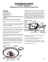
WHAT TO DO WHEN YOUR RV/TV ANTENNA IS NOT WORKING PROPERLY<br />
INSTALLING COAX CABLE ON<br />
FC- 5910 CONNECTO<strong>RS</strong><br />
HOW YOUR<br />
SYSTEM WORKS<br />
AMPLIFIED<br />
TV SIGNAL<br />
WHITE<br />
STEP 1: Strip outer cover back 1/2"* from end of cable. Fray braid back<br />
as far as outer cover will allow.<br />
STEP 2: Trim braid close to outer cover and remove 1/4"* of inner insulation<br />
being careful not to nick center conductor. Make sure no foil or braid can<br />
touch center conductor.<br />
STEP 3: Slide connector tip between braid and inner insulation (braid and<br />
foil, on foil shield cable) and push connector on cable as far as it will go.<br />
Crimp built-in ferrule with appropriate crimping tool. Do Not crush cable<br />
out-of-round. *If installing in very hot weather, increase these dimensions<br />
1/8".<br />
* If installing in very hot weather, increase these dimensions 1/8".<br />
GND -<br />
HOOKS INTO +12VDC BATTERY +<br />
2ND SET<br />
HOOK UP<br />
SET 2<br />
RED<br />
+12VDC<br />
ANTENNA<br />
CONNECTION<br />
WARNING<br />
DO NOT INSTALL COUPLE<strong>RS</strong>, SPLITTE<strong>RS</strong>, ETC.<br />
BETWEEN THE POWER SUPPLY AND THE AN-<br />
TENNA. INSTALLATION OF ANY ITEM ON THE DOWN-<br />
LEAD MAY CAUSE A SHORT IN THE SYSTEM. THE<br />
DOWNLEAD SUPPLIES +12 VDC TO THE PREAMP IN<br />
THE ANTENNA.<br />
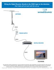
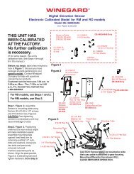
HOW YOUR SYSTEM WORKS<br />
Turning power supply on sends +12 VDC up cable to<br />
antenna. Voltage energizes transistors on amplifier in<br />
antenna head. TV signal comes back down cable to<br />
outlets.<br />
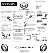
TO TEST SYSTEM<br />
TEST POINT #1<br />
+12VDC AT ANTENNA<br />
+ Point center wire<br />
- Point outside of<br />
connector<br />
TO TEST SYTEM<br />
1. Make sure TV set is working properly.<br />
2. Switch power supply ON and OFF to see if there is a<br />
difference in the picture quality while watching TV. If<br />
there is NO difference, proceed to the next step.<br />
CAUTION<br />
The power supply should be turned OFF when connecting/disconnecting<br />
cables to power supply and<br />
antenna, but should be turned ON when testing for<br />
voltage.<br />
3. Disconnect cable from antenna and check for +12<br />
VDC at test point #1. If there is +12 VDC, the power<br />
supply is OK and the antenna needs to be replaced.<br />
4. If there is no +12 VDC at test point #1 reconnect the<br />
cable to antenna. Remove power supply from wall and<br />
visually inspect for burnt/broken parts. If there are any<br />
broken or burnt parts replace power supply.<br />
5. Disconnect cable from antenna jack on power supply.<br />
Check for +12 VDC at test point #2. If there is +12 VDC<br />
then there is a problem in the cable connecting the<br />
power supply to the antenna. Repair/ replace cable.<br />
2ND SET<br />
NO +12VDC<br />
AT THIS POINT<br />
GND<br />
+ 12VDC<br />
SET 2<br />
WHITE<br />
RED<br />
AT SET 2 JACK<br />
REMOVE CABLE<br />
FROM ANTENNA<br />
ANTENNA<br />
CONNECTION<br />
TEST POINT #2<br />
+12VDC AT<br />
ANT. JACK<br />
FIGURE 1 FIGURE 2 FIGURE 3 FIGURE 4<br />
6. If +12 VDC is not present at test point #2, check that<br />
the red indicator is ON. If not, check the polarity of the red/<br />
white wires and check the +12 VDC source. If there is still<br />
no +12 VDC replace the power supply.<br />
RF CHOKE RF CHOKE POLYSWITCH POLYSWITCH<br />
POWER SUPPLY<br />
IN METAL HOUSING<br />
POWER SUPPLY<br />
NO POLYSWITCH<br />
POWER SUPPLY<br />
W/POLYSWITCH<br />
POWER SUPPLY<br />
W/POLYSWITCH<br />
4