Owners Manual - Imtra
Owners Manual - Imtra
Owners Manual - Imtra
Create successful ePaper yourself
Turn your PDF publications into a flip-book with our unique Google optimized e-Paper software.
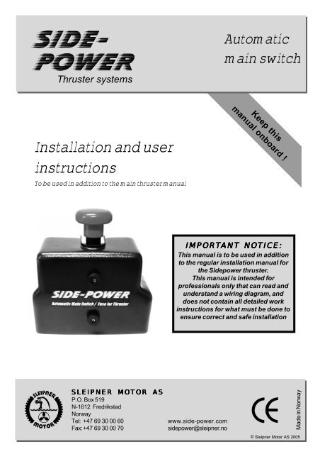
SIDE-<br />
POWER<br />
Thruster systems<br />
Automatic<br />
main switch<br />
Keep this<br />
manual onboard !<br />
Installation and user<br />
instructions<br />
To be used in addition to the main thruster manual<br />
IMPORTANT NOTICE:<br />
This manual is to be used in addition<br />
to the regular installation manual for<br />
the Sidepower thruster.<br />
This manual is intended for<br />
professionals only that can read and<br />
understand a wiring diagram, and<br />
does not contain all detailed work<br />
instructions for what must be done to<br />
ensure correct and safe installation<br />
SLEIPNER MOTOR AS<br />
P.O. Box 519<br />
N-1612 Fredrikstad<br />
Norway<br />
Tel: +47 69 30 00 60<br />
Fax:+47 69 30 00 70<br />
www.side-power.com<br />
sidepower@sleipner.no<br />
Made in Norway<br />
© Sleipner Motor AS 2005
Installation of the Sidepower automatic main switch<br />
Note! To achieve maximum effect, reliability and durability from your Sidepower thruster, a correct<br />
installation as per the instructions are very important. Please follow the instructions carefully, and<br />
make sure that all checkpoints are carefully controlled.<br />
INTRODUCTION - DESCRIPTION OF FUNCTION:<br />
The Sidepower automatic main switch product was developed to further enhance the safety and<br />
ease of use of a Sidepower thruster system. The automatic main switch ensures that there is no<br />
power at the thruster unless you actually intend to use the thruster. It is controlled by the Sidepower<br />
control panel / Sidepower control device, and also benefits from the Auto-Off features in<br />
these products so that if you forget to shut it off, it will automatically shut off after a preset time.<br />
This also means that in case of a failure, the main switch is fast and easy to shut off without leaving<br />
the steering position simply by pushing the OFF on the control panel, which should be the logic thing<br />
to do even in a panic situation.<br />
To comply with regulations the automatic mainswitch also has a mechanical shut-off feature on the<br />
main switch itself. This is a backup in case there is a failure in the switch.<br />
The built-in fuse holder is made for ANL type fuses with special provisions to reduce voltage drop<br />
and heating. By the fuse being part of the unit, you avoid fitting two seperate items to comply with<br />
having both a fuse and a main switch on the thruster main circuit.<br />
INSTALLATION PLANNING AND PRECAUTIONS:<br />
• The automatic main switch should be fitted as close to the battery(ies) as possible.<br />
• Do not fit the automatic main switch with other than the appropriate original Sidepower control<br />
panels or other Sidepower control devices spesifically designed for this with a seperate fifth<br />
control lead for the automatic main switch.<br />
• It is designed to fit on a shelf or a wall and must be fitted so that it keeps dry at all times.<br />
• The automatic main switch can NOT be fitted in spaces requiring Ignition protected equipment.<br />
• Make sure that the fuse you order for the main switch is the correct one for the thruster it is<br />
being fitted with.<br />
• The control cables must be routed differently from an installation without this automatic main<br />
switch so that the 4-lead control cable from the thruster follows the main battery cables to the<br />
main switch, and then you use 5-lead control cables from the main switch to the control panels.<br />
This can accomodate basically an unlimited number of Sidepower controls, including a radio<br />
remote by branching off with Y-connectors.<br />
• If any of the Sidepower control panels are situated outside or in a place where they can be<br />
accessed when the boat is not in use, the control power for the automatic main switch should be<br />
taken over another main switch that will be off when the boat is not in use.<br />
• Failure to install the automatic main switch in accordance with this manual will render all warranty<br />
void and can cause malfunction or even serious damages.<br />
Automatic Main Switch intallation manual 1.5 - 2006<br />
2
Installation of the Sidepower automatic main switch<br />
Fitting the fuse and battery cable(s).<br />
- Remove the nuts and all the washers (B,<br />
D and F).<br />
- Fit the fuse (C) on top of the pre-fitted<br />
conductors (A) and washer (B).<br />
- Fit the washers ( D) and battery cable(s)<br />
(E) as shown below.<br />
- Fit the washers and nut( F).<br />
- Tighten the nut carefully with 20Nm(14.5<br />
lb/ft) torque, as the brass bolt is weaker<br />
than a steel bolt.<br />
F<br />
E<br />
D<br />
Fuse<br />
holder<br />
Description of the automatic main switch<br />
<strong>Manual</strong> over ride button.<br />
Push to shut OFF<br />
Pull to activate ON<br />
C<br />
B<br />
A<br />
Main cable(s) from<br />
battery(ies)<br />
Main cable(s)<br />
to thruster<br />
Notice<br />
sequence<br />
F<br />
D E C<br />
B<br />
A<br />
Fitting the thruster cable(s)<br />
- Remove the nuts and washers (C, D and<br />
E).<br />
- Fit the cable or cables (B) as shown<br />
directly onto the pre-fitted conductor (A).<br />
- Fit the washers in sequence as shown<br />
with the flat washer (C) on top of the<br />
cable and the springwasher (D) under the<br />
nut (E).<br />
E<br />
D<br />
C<br />
B<br />
A<br />
<strong>Manual</strong> override button.<br />
- Pull OUT for ON<br />
- Push IN for OFF<br />
- Leave the switch in ON position when<br />
on board<br />
- Make sure the switch is in OFF position<br />
when leaving the boat for a long<br />
period or when you are installing or<br />
servicing the thruster system<br />
Pull out<br />
ON<br />
Push in<br />
OFF<br />
Automatic Main Switch intallation manual 1.5 - 2006<br />
3
Instructions<br />
Wiring of the automatic main switch<br />
- Fit the automatic mainswitch as close to the battery(ies) as possible making sure that it is in a position so that it will<br />
stay dry at all times.<br />
- Use a 4-lead control cable between the thruster and the automatic mainswitch (only 3 leads is in actual use, red is<br />
not wired into the automatic mainswitch).<br />
- Use 5-lead control cables between automatic mainswitch and control panels, using 5-lead Y-connectors to branch<br />
off to to all controls fitted.<br />
- Use the table in the thrusters manual for deciding the main cable sizes, the lengths are the total of positive and negative, all the way from<br />
the battery.<br />
5-lead<br />
control cables<br />
4-lead<br />
control cable<br />
Seperate power<br />
feed to automatic<br />
main switch<br />
Main battery<br />
cables<br />
DESCRIPTION OF WIRING DIAGRAMS (as shown on opposite page):<br />
A Main switch with fuse, 12 or 24V version.<br />
Order correct fuse size depending on thruster it is being fitted with<br />
B The thruster panel(s) ON/OFF system with timer auto-off and safe dual ON button activation controls the Automatic<br />
main power switch<br />
C The thermal switch built into the thruster motor which supply all the negative/ground to the panel so that in an overheat<br />
situation also the automatic main power switch will be shut off.<br />
D To prevent the possibility of the thruster being activated by an outside mounted thruster panel when nobody is<br />
onboard, the positive control power must be supplied over one of the boats main battery switches or alternatively the<br />
ignition switch if you wish to prevent usage of the thruster unless the main engine is running. This power feed must<br />
be fused to protect the wire.<br />
- If there are no outdoor control panels or the main power to the automatic mainswitch is supplied through one of the<br />
boats manual mainswitches, this wire can be connected to the main positive input terminal on the automatic<br />
mainswitch in which case it does not need to be fused. If so, the automatic mainswtich can always be activated by<br />
any panel on board.<br />
E The mainswitch must have a negative power feed for its solenoid.<br />
When you fit two thrusters you need to fit an automatic main switch for each thruster, except for the models SP30S2i,<br />
SP40S2i, SP55Si12, SP55Si24 and SP75Ti24 for which one automatic mainswitch can support two thruster because of the<br />
low current consumption. This installation also requires that only one battery bank is used to power both thrusters.<br />
It is important that the battery banks powering the thrusters have a common negative so that the voltage potential is equal. If<br />
this is not so in the boat you are installing the thrusters in, both thrusters have to be powered from one battery bank (of<br />
sufficient size).<br />
Automatic Main Switch intallation manual 1.5 - 2006<br />
4
Wiring diagrams<br />
Single thruster wiring<br />
Dual thrusters wiring<br />
Automatic Main Switch intallation manual 1.5 - 2006<br />
5
Instructions and wiring diagram for use with series / parallel switch box installation<br />
Description:<br />
IMPORTANT ! Only newer version AutoMainswitch<br />
- Fit the automatic mainswitch as close to the battery as possible.<br />
is compatible with series / parallel box installations<br />
!<br />
- Use a 4-lead control cable between the thruster and the automatic mainswitch.<br />
- Use 5-lead control cables between automatic mainswitch and control panels, using 5-lead Y-connectors to branch off to to all controls fitted.<br />
- Use the table in the thrusters manual for deciding the main cable sizes, the lengths are the total of positive and negative, all the way from the battery.<br />
A Main switch with fuse, 12 or 24V version. Use the version of the boats original voltage, so that for SP155, 200 or 240 being fitted in 12V boats, use<br />
12V mainswitch. For SP285TC fitted in 24V boat use 24V mainswitch. Select fuse size depending on thruster.<br />
B The thruster panel(s) ON/OFF system with timer auto-off and safe dual ON button activation controls the Automatic main power switch.<br />
C The thermal switch built into the thruster motor which supply all the negative/ground to the panel so that in an overheat situation also the automatic main<br />
power switch will be shut off.<br />
D When installing the automatic mainswitch in a series / parallel type installation the power to the internal functions of the automatic mainswitch must be<br />
taken from the systems batt. 1 so that it is in the boats native/original voltage level.<br />
E The mainswitch must have a negative power feed for its solenoid and this must also be taken from the batt. 1 negative so that it is always at the boats<br />
general negative/ground voltage.<br />
F Install and wire series / parallel box as described in its installation instructions, replacing the fuse and mainswitch between batt. 2 and the thruster with<br />
this automatic mainswitch.<br />
Dotted lines here only show schematically the other main cables used when fitting a series/parallel systrem, refer to detailed instructions in the actual<br />
installation manual of this item.<br />
G A fuse and manual main switch should be fitted between battery bank 1 and the series parallel switch box so that it can be shut down in case of a fault.<br />
However, this should be left on at all times to ensure charge of ”Batt. 2" and only be disconnected when installing / servicing or in case of a failure.<br />
PS! Do NOT use an automatic mainswitch between Batt 1 and Batt 2 as this will prevent charging of batt.2. The mainswitch between the batteries are only<br />
for emergencies and should always be left in the ON position except in emergencies.<br />
Wiring with series / parallel<br />
switch box installation<br />
Automatic Main Switch intallation manual 1.5 - 2006<br />
6
Control<br />
panel 1<br />
”bow”<br />
”stern”<br />
For more control panels,<br />
use Y-cables and exension<br />
cables connected from<br />
control panel 1<br />
Control cables between<br />
panels and AMS must be<br />
5-lead.<br />
Control cables going<br />
directly to thrusters can be<br />
4-lead<br />
Fuse<br />
Bow<br />
Fuse<br />
Stern<br />
B1<br />
B2<br />
Control power supply 12/24V.<br />
See manual for<br />
Automatic Main Switch<br />
red<br />
Automatic<br />
Main<br />
Switch<br />
12/24V<br />
black<br />
Main<br />
Fuse<br />
M<br />
Battery<br />
(bank)<br />
12 / 24V<br />
M<br />
A1<br />
A2<br />
Bow<br />
thruster<br />
Stern<br />
thruster<br />
IMPORTANT NOTICES!<br />
Total current consumption for the two thrusters must not exceed max. current for the Automatic Main Switch (AMS). See manuals.<br />
It will normally be the most efficient to fit additional and dedicated fuses for each thruster, protecting each thrusters consumption and<br />
cable size individually. This is an absolute requirement if different cable sizes are used for the two thrusters. See installasion manual for<br />
the thrusters for minimum cable sizes depending on cable lengths and appropriate fuse sizes.<br />
In the AMS, use the fuse size that is the total of the adviced fuses for the two thrusters fitted.<br />
If no separate fuses for bow and stern thruster is fitted in addition to the one in the AMS, the main cable sizes used to each thruster<br />
must be equal and compatible with the size of the main fuse in the AMS. (A1,B1 = A2,B2)<br />
The control power supply (red, seperate lead into AMS) must be from a source that have common negative with the battery(ies)<br />
powering the thrusters.<br />
2 thrusters on<br />
1 Automatic Main Switch<br />
Sleipner Motor AS<br />
P.O. Box 519<br />
N-1612 Fredrikstad<br />
Norway<br />
Tel: +47 69 30 00 60<br />
Drawn:<br />
L.G. 20.04.2006<br />
Draw no:<br />
ETH-A00-303-01
Service / maintenance / trouble shooting<br />
Service / maintenance<br />
- The automatic mainswitch does not require spesific service or maintenance other than normal service and control that should be performed<br />
on all electric equipment regularly which includes:<br />
- Keeping the equipment clean and dry.<br />
- Making sure all cable and other connections are tight and without signs of excessive heat or corrosion.<br />
Trouble shooting<br />
The control panel will not activate:<br />
- Make sure that the automatic mainswitch is getting positive feed over its red thin lead. If this goes over another main switch in the boat, make sure that<br />
this is ON.<br />
- Check that the internal overheat switch (bi-metal switch on the circuit board) in the automatic main switch has not opened. It is automatically re-setting so<br />
that if it is open while the mainswitch is cold, contact your nearest Sidepower service for assistance. You should also investigate the reason why it<br />
opened in the first place.<br />
- Check 5A fuse installed on the red positive cable to the automatic main switch.<br />
- Check that the overheat switch in the electromotor has not blown due to excessive heat.<br />
- Check all control cable connections against the wiring diagrams in this manual and the thrusters manual.<br />
The control panel activates, but the thruster will not run<br />
- Make sure that the manual over-ride knob is in “ON” position (pulled out).<br />
- Check that the main power fuse in the automatic mainswitch is OK - if it is blown, please ensure that it is the right size. If it is the correct size<br />
but the fuse continue to blow, the reason for this must be identified.<br />
- Check if the main switch activates when the control panel is activated. If not, please check the wiring, especially that you have a constant<br />
seperate negative feed (thin black lead) and that the control panel is feeding a positive into the yellow lead.<br />
- Check that there is power at the thruster. If it is not while the previous points are checked OK, the main cable run must be checked.<br />
- If there is power at the thruster, measure the voltage at the main battery cable connection points into the thruster while you are trying to run<br />
the thruster. If this is below 8,5V (12V system) or 16V (24V system) control the batteries and main cable runs to find the reason for the<br />
excessive voltage drop.<br />
- Go through the trouble shooting in the thrusters manual.<br />
If you are unable to identify and resolve the problem by these actions, please contact the nearest Sidepower service point for assistance and<br />
please have the notes from your trouble shooting handy to inform the service person of what you have already checked and found.<br />
DECLARATION OF CONFORMITY<br />
We, Sleipner Motor AS<br />
P.O. Box 519<br />
N-1612 Fredrikstad, Norway<br />
declare that this product complies with the essential health and<br />
safety requirements according to Directive 89 / 336 / EEC of 23<br />
May 1989 amended by 92 / 31 / EEC and 93 / 68 / EEC.<br />
Automatic Main Switch intallation manual 1.5 - 2006<br />
7
Argentina<br />
Trimer SA<br />
Buenos Aires<br />
Tel: +54 11 4580 0444<br />
Fax: +54 11 4580 0440<br />
www.trimer.com.ar<br />
trimer@trimer.com.ar<br />
Australia<br />
AMI Sales<br />
Freemantle, WA<br />
Tel: +61 89 337 3266<br />
Fax: +61 89 314 2929<br />
ami@amisales.com.au<br />
Austria<br />
G. Ascherl GmbH<br />
Hard, Bregenz<br />
Tel: +43 5574 899000<br />
Fax: +43 5574 89900-10<br />
www.ascherl.at<br />
office@ascherl.at<br />
Benelux<br />
ASA Boot Electro<br />
Watergang<br />
Tel: +31 20 436 9100<br />
Fax: +31 20 436 9109<br />
asaboot@worldonline.nl<br />
info@asabootelectro.nl<br />
Canada<br />
<strong>Imtra</strong> Corporation<br />
New Bedford, MA<br />
Tel: +1 508 995 7000<br />
Fax: +1 508 998 5359<br />
www.imtra.com<br />
side-power@imtra.com<br />
Croatia<br />
AC Yacht & nautical support<br />
Icici<br />
Tel: +385 51 704 500<br />
Fax: +385 51 704 600<br />
acy@net.hr<br />
Denmark<br />
Gertsen & Olufsen AS<br />
Hørsholm<br />
Tel: +45 4576 3600<br />
Fax: +45 4576 1772<br />
www.gertsen-olufsen.dk<br />
info@gertsen-olufsen.dk<br />
Finland<br />
Nautikulma OY<br />
Turku<br />
Tel: +358 2 2503 444<br />
Fax: +358 2 2518 470<br />
www.nautikulma.fi<br />
nautikulma@kolumbus.fi<br />
France<br />
Kent Marine Equipment<br />
Nantes<br />
Tel: +33 240 921 584<br />
Fax: +33 240 921 316<br />
www.kent-marine.com<br />
contact@kent-marine.com<br />
Germany<br />
Jabsco GmbH<br />
Norderstedt<br />
Tel: +49 40 535 373-0<br />
Fax: +49 40 535 373-11<br />
Greece<br />
Amaltheia Marine<br />
Athens<br />
Tel: +30 210 2588 985<br />
Fax: +30 210 2588 986<br />
www.amaltheiamarine.com<br />
amalmar@otenet.gr<br />
Iceland<br />
Merkur HF<br />
Reykjavik<br />
Tel: +354 594 6000<br />
Fax: +354 594 6001<br />
www.merkur.is<br />
merkur@merkur.is<br />
Ireland<br />
Metalcove Marine<br />
Dublin<br />
Tel: +353 1 668 6046<br />
Fax: +353 1 668 6827<br />
www.metalcove.com<br />
Israel<br />
Atlantis Marine Ltd.<br />
Tel Aviv<br />
Tel: +972 3 522 7978<br />
Fax: +972 3 523 5150<br />
www.atlantis-marine.com<br />
atlantis@inter.net.il<br />
Italy<br />
Saim S.P.A.<br />
Assago-Milan<br />
Tel: +39 02 488 531<br />
Fax: +39 02 488 254 5<br />
www.saim.group.com<br />
Japan<br />
Global Marine Inc.<br />
Hyogo<br />
Tel: +81 798 347 345<br />
Fax: +81 798 347 346<br />
www.global-marine.co.jp<br />
info@global-marine.co.jp<br />
Service Centres<br />
Malta<br />
S & D Yachts Ltd.<br />
Cali<br />
Tel: +356 21 339 908<br />
Fax: +356 21 332 259<br />
www.sdyachts.com<br />
info@sdyachts.com<br />
New Zealand<br />
Lusty & Blundel Ltd.<br />
Auckland<br />
Tel: +64 9 415 8303<br />
Fax: +64 9 415 8304<br />
www.lusty-blundell.co.nz<br />
sales@lusty-blundell.co.nz<br />
Norway<br />
Sleipner Motor AS<br />
Fredrikstad<br />
Tel: +47 69 30 00 60<br />
Fax: +47 69 30 00 70<br />
www.side-power.com<br />
sidepower@sleipner.no<br />
Poland<br />
Taurus Sea Power SP. Z.O.O<br />
Gdansk<br />
Tel: +48 58 344 30 50<br />
Fax: +48 58 341 67 62<br />
Portugal<br />
Krautli Portugal Lda.<br />
Lisboa<br />
Tel: +351 21 953 56 00<br />
Fax: +351 21 953 56 01<br />
www.krautli.com<br />
contact@krautli.pt<br />
Russia<br />
Standarte<br />
Starbeyevo<br />
Tel: +7 095 575 67 23<br />
Fax: +7 095 575 39 77<br />
www.standarte.ru<br />
info@standarte.ru<br />
Spain<br />
Imnasa Marine Products<br />
Girona<br />
Tel: +34 972 820210<br />
Fax: +34 972 325116<br />
www.imnasa.com<br />
imnasa@imnasa.com<br />
Sleipner Motor AS, P. O. Box 519, N-1612 Fredrikstad, Norway<br />
Tel: +47 69 30 00 60 Fax: +47 69 30 00 70 sidepower@sleipner.no www.side-power.com<br />
Sweden<br />
Sleipner AB<br />
Strömstad<br />
Tel: +46 526 629 50<br />
Fax: +46 526 152 95<br />
www.sleipnerab.se<br />
Switzerland<br />
Marineparts Heimgartner<br />
Volketswil<br />
Tel: +41 1 997 40 90<br />
Fax: +41 1 997 40 94<br />
www.marineparts.ch<br />
info@marineparts.ch<br />
Singapore/Malaysia/<br />
Indonesia<br />
Alquest Marketing<br />
Singapore<br />
Tel: +65 6749 9359<br />
Fax: +65 6749 9360<br />
www.alquest.com.sg<br />
alquest@singnet.com.sg<br />
Taiwan<br />
Mercury Marine Supply<br />
Kaohsiung<br />
Tel: +886 7 8133 233<br />
Fax: +886 7 8133 236<br />
Turkey<br />
Denpar Ltd.<br />
Istanbul<br />
Tel: +90 212 285 0334<br />
Fax: +90 212 285 0311<br />
bilgebay@superonline.com<br />
UK<br />
Sleipner Motor Ltd.<br />
South Brent<br />
Tel: +44 1364 649 400<br />
Fax: +44 1364 649 399<br />
andy@sleipner.co.uk<br />
United Arab Emirates<br />
Teignbridge Propulsion<br />
Dubai<br />
Tel: +971 4 324 0084<br />
Fax: +971 4 324 0153<br />
teignpro@emirates.net.ae<br />
USA<br />
<strong>Imtra</strong> Corporation<br />
New Bedford, MA<br />
Tel: +1 508 995 7000<br />
Fax: +1 508 998 5359<br />
www.imtra.com<br />
side-power@imtra.com<br />
All other:<br />
Sleipner Motor AS<br />
Automatic Main Switch installation manual 1.4 - 2005 8


