Teejet Catalog 51 - Farmco Distributing Inc
Teejet Catalog 51 - Farmco Distributing Inc
Teejet Catalog 51 - Farmco Distributing Inc

Create successful ePaper yourself
Turn your PDF publications into a flip-book with our unique Google optimized e-Paper software.
<strong>Catalog</strong> <strong>51</strong><br />
Leaders in precision<br />
application components,<br />
control system technology,<br />
and application data<br />
management.<br />
www.teejet.com
Table of Contents<br />
Selection Guide<br />
TeeJet® Broadcast Nozzle Selection Guide ............ 2<br />
TeeJet Specialty Application Nozzle<br />
Selection Guide ................................... 3<br />
TeeJet Liquid Fertilizer Nozzle Selection Guide. . . . . . . . 4<br />
Broadcast Nozzles<br />
Turbo TeeJet® Wide Angle Flat Spray Tips ............ 5<br />
AIXR TeeJet Air Induction Flat Spray Tips .............. 6<br />
AI TeeJet Air Induction Flat Spray Tips ................ 7<br />
AIC TeeJet Air Induction Flat Spray Tips ............... 8<br />
Turbo TeeJet Induction Flat Spray Tips ............... 9<br />
XR TeeJet® Extended Range Flat Spray Tips ..........10<br />
XRC TeeJet Extended Range Flat Spray Tips. . . . . . . . . . 11<br />
TeeJet VisiFlo® Flat Spray Tips .......................12<br />
DG TeeJet® Drift Guard Flat Spray Tips ...............13<br />
Turbo TwinJet® Twin Flat Spray Tips .................14<br />
Air Induction Turbo TwinJet Twin Flat Spray Tips .....15<br />
TwinJet® Twin Flat Spray Tips ........................16<br />
Turbo TeeJet Duo Dual Polymer Flat Fan Spray Tips ..17<br />
DG TwinJet® Drift Guard Twin Flat Spray Tips .........18<br />
Turbo FloodJet® Wide Angle Flat Spray Tips .........19<br />
FloodJet® Wide Angle Flat Spray Tips .............. 20<br />
Quick Turbo FloodJet Wide Angle<br />
Flat Spray Tips ....................................21<br />
TurfJet Wide Angle Flat Fan Spray Nozzles ...........22<br />
TeeJet Double Outlet Flat Spray Tips ................23<br />
TeeJet Off-Center Flat Spray Tips –<br />
Smaller Capacities ................................23<br />
FullJet® Wide Angle Full Cone Spray Tips .............24<br />
Boomless Nozzles<br />
XP BoomJet® Boomless Flat Spray Nozzles ..........25<br />
BoomJet® Boomless Nozzles with Extra Wide<br />
Flat Spray Projection .............................26<br />
TeeJet Swivel Spray Nozzles with Off-Center<br />
Flat Spray Tips—Larger Capacities .............. 26<br />
FieldJet® Boomless Nozzles with Extra Wide<br />
Flat Spray Projection .............................27<br />
Banding Nozzles<br />
ConeJet® VisiFlo Hollow Cone Spray Tips ............28<br />
AI TeeJet Air Induction Even Flat Spray Tips ........29<br />
DG TeeJet Drift Guard Even Flat Spray Tips .........30<br />
TeeJet Even Flat Spray Tips .........................31<br />
TwinJet Even Flat Spray Tips ........................32<br />
AIUB TeeJet Banding and Directed<br />
Spray Nozzles ....................................33<br />
TeeJet Full Cone Spray Tips .........................34<br />
TeeJet UB—Underleaf Banding Spray Tips ............34<br />
ConeJet Ceramic VisiFlo Spray Tips ..................35<br />
Air Blast Nozzles<br />
ConeJet VisiFlo Hollow Cone Spray Tips .............36<br />
ConeJet VisiFlo Hollow Cone Spray Tips .............37<br />
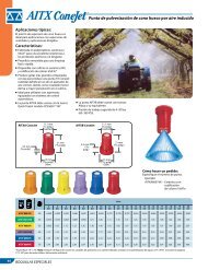
AITX ConeJet Air Induction Hollow Cone Spray Tip ...38<br />
ConeJet VisiFlo Hollow Cone Spray Tips .............39<br />
TeeJet VisiFlo Flat Spray Tips .........................39<br />
TeeJet Disc-Core Type Hollow Cone Spray Tips .......40<br />
TeeJet Disc-Core Type Full Cone Spray Tips ..........41<br />
Fertilizer Nozzles<br />
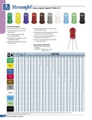
StreamJet SJ3 Fertilizer Nozzles ......................42<br />
StreamJet SJ7 Fertilizer Nozzles ......................43<br />
TeeJet Flow Regulators ..............................44<br />
StreamJet Solid Stream Spray Nozzles ...............45<br />
Tank Rinsing Nozzles<br />
TeeJet Tank Rinsing Nozzles .........................46<br />
TeeJet Container Rinsing Nozzles ....................46<br />
TeeJet Eductor Nozzles ..............................47<br />
TeeJet Jet Agitators. . . . . . . . . . . . . . . . . . . . . . . . . . . . . . . . . . 47<br />
Boom Components<br />
Quick TeeJet® Multiple Nozzle Body<br />
Assemblies for Dry Booms .......................48<br />
TeeJet Vari-Spacing Clamps for Use<br />
on Dry Boom Quick TeeJet Bodies ................48<br />
Quick TeeJet Multiple Nozzle Body Assemblies<br />
for Dry Booms ....................................49<br />
Quick TeeJet Multiple Nozzle Body Assemblies ......50<br />
Quick TeeJet Multiple Nozzle Body Assemblies<br />
with Fertilizer Outlets for Dry Booms .............50<br />
Quick TeeJet Single Nozzle Bodies<br />
for Dry Booms ....................................<strong>51</strong><br />
Quick TeeJet Multiple Nozzle Bodies<br />
for Wet Booms ............................... 52–53<br />
Quick TeeJet Triple Nozzle Bodies<br />
for Wet Booms ...................................54<br />
Quick TeeJet Multiple Nozzle Body Assemblies<br />
with Fertilizer Outlets for Wet Booms .............54<br />
Quick TeeJet Multiple Nozzle Bodies<br />
for Wet Booms ...................................55<br />
www.teejet.com
Quick TeeJet Single Nozzle Bodies<br />
for Wet Booms ....................................56<br />
Quick TeeJet Caps for Hardi® Nozzle Bodies...........56<br />
Quick TeeJet Caps....................................57<br />
Quick TeeJet Adapters and Accessories...............58<br />
TeeJet ChemSaver® Diaphragm Check Valves.........59<br />
TeeJet Nozzle Body ChemSaver Check Valves.........60<br />
TeeJet Speciality Fittings..............................61<br />
TeeJet Row Application Kit ...........................61<br />
TeeJet Swivel Nozzle Bodies..........................62<br />
TeeJet Hose Drops....................................62<br />
TeeJet Hose Shank Nozzle Bodies.....................63<br />
TeeJet Split Eyelet Nozzle Bodies.....................63<br />
TeeJet Nozzle Parts............................... 64–65<br />
Valves & Manifolds<br />
DirectoValve® B Style Electric Motors and Valves......66<br />
DirectoValve B Style Motors..........................67<br />
DirectoValve Electric Regulating Valves...............68<br />
DirectoValve Flow Back Manifolds....................69<br />
DirectoValve Electric Regulating Ball Valves....... 70–71<br />
DirectoValve 344 Series Electric<br />
Shutoff Valves................................. 72–73<br />
DirectoValve 346 Series Shutoff Valves ........... 74–75<br />
DirectoValve 356 Series Flanged<br />
Shutoff Valves................................. 76–77<br />
DirectoValve Normally-Open (Bypass) Valves ..... 78–79<br />
DirectoValve 430 Series 2-Way Manifold..............80<br />
DirectoValve 430 Series 3-Way Manifold..............81<br />
DirectoValve 430 Series Flow Back Manifold...... 82–83<br />
DirectoValve Control Unit for TeeJet Controllers .. 84–85<br />
Individual 430 Manifold Accessories................... 85<br />
DirectoValve 440 Series Manifold<br />
Shutoff Valves................................. 86–87<br />
DirectoValve 450 Series Shutoff Manifold......... 88–89<br />
DirectoValve 450 Series Flow Back Manifold...... 90–91<br />
DirectoValve 460 Series 2-Way Manifold.......... 92–93<br />
DirectoValve 460 Series 3-Way Manifold.......... 94–95<br />
DirectoValve 460 Series Flow Back Manifold...... 96–97<br />
DirectoValve 490 Series Shutoff Manifold......... 98–99<br />
DirectoValve 540 Series Shutoff Manifold...... 100–101<br />
DirectoValve Flange Fittings................... 102–103<br />
DirectoValve Quick Connect Fittings................ 104<br />
DirectoValve Electrical Connectors ................. 105<br />
DirectoValve 2-Way Electrically<br />
Operated Solenoid Valves....................... 106<br />
DirectoValve 3-Way Electrically<br />
Operated Solenoid Valves....................... 107<br />
DirectoValve Solenoid Foam Marker Valves......... 107<br />
DirectoValve 340 Series<br />
2-Way Manual Shutoff Ball Valves ............... 108<br />
DirectoValve 340 Series<br />
3-Way Manual Bypass Ball Valves................ 109<br />
DirectoValve Manual Pressure<br />
Relief/Regulating Valves......................... 110<br />
DirectoValve Manual Control Valves................ 111<br />
TeeValve® Control Valves........................... 111<br />
TeeJet Throttling Valves............................ 111<br />
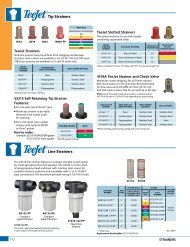
Strainers<br />
TeeJet Tip Strainers................................. 112<br />
TeeJet Line Strainers........................... 112–115<br />
Spray Guns<br />
GunJet® Spray Guns...................... 116–117, 119<br />
MeterJet® Spray Guns .............................. 118<br />
TeeJet Lawn Spray Guns............................ 118<br />
TriggerJet® Spray Guns........................ 120–121<br />
ConeJet Adjustable Spray Tips...................... 122<br />
TeeJet Shutoff Valves and Spray Guns.............. 123<br />
Technical Information<br />
Formulas and Factors.......................... 124–125<br />
Spray Coverage Information........................ 125<br />
Nozzle Nomenclature .............................. 125<br />
Universal Application Rate Chart .............. 126–127<br />
Information About Spray Pressure.................. 128<br />
Pressure Drop Through Sprayer Componants....... 129<br />
Area Measurement................................. 130<br />
Sprayer Calibration................................. 131<br />
Calibration/Adjustment Accessories................ 132<br />
Spray Tip Wear. . . . . . . . . . . . . . . . . . . . . . . . . . . . . . . . . . . . . . 133<br />
Spray Distribution Quality.......................... 134<br />
Droplet Size and Drift Information.................. 135<br />
Drop Size Classification........................ 136–137<br />
Drift Causes and Control....................... 138–139<br />
Assesment of Nozzle Drift Control in Europe........ 140<br />
Plumbing Diagrams................................ 141<br />
Notes.......................................... 142–143<br />
Terms and Conditions.............................. 144<br />
The Easy Decision for Precision.
Broadcast Nozzle Selection Guide<br />
Herbicides fungicides insecticides<br />
soil<br />
applied<br />
Post-emergence<br />
contact<br />
systemic<br />
contact systemic contact systemic<br />
drift<br />
management<br />
Reference page 5<br />
very<br />
GOOD<br />
very<br />
GOOD<br />
very<br />
GOOD<br />
very<br />
GOOD<br />
very<br />
GOOD<br />
very<br />
GOOD<br />
very<br />
GOOD<br />
at pressures below 30 PSI (2.0 bar)<br />
Reference page 5<br />
GOOD GOOD EXCELLENT GOOD EXCELLENT GOOD EXCELLENT<br />
very<br />
GOOD<br />
Reference page 14<br />
GOOD<br />
EXCELLENT EXCELLENT EXCELLENT EXCELLENT EXCELLENT EXCELLENT<br />
very<br />
GOOD<br />
at pressures below 30 PSI (2.0 bar)<br />
Reference page 14<br />
very<br />
GOOD<br />
very<br />
GOOD<br />
EXCELLENT<br />
very<br />
GOOD<br />
EXCELLENT<br />
very<br />
GOOD<br />
EXCELLENT EXCELLENT<br />
Reference page 9<br />
EXCELLENT EXCELLENT EXCELLENT EXCELLENT EXCELLENT<br />
Reference page 15<br />
very<br />
GOOD<br />
GOOD EXCELLENT GOOD EXCELLENT GOOD EXCELLENT EXCELLENT<br />
,<br />
Reference pages 10–11<br />
EXCELLENT GOOD EXCELLENT GOOD EXCELLENT GOOD GOOD<br />
,<br />
at pressures below 30 PSI (2.0 bar)<br />
Reference pages 10–11<br />
GOOD<br />
GOOD<br />
very<br />
GOOD<br />
GOOD<br />
very<br />
GOOD<br />
GOOD<br />
very<br />
GOOD<br />
very<br />
GOOD<br />
Reference page 6<br />
very<br />
GOOD<br />
GOOD EXCELLENT GOOD EXCELLENT GOOD EXCELLENT EXCELLENT<br />
,<br />
Reference pages 7–8<br />
very<br />
GOOD<br />
GOOD EXCELLENT GOOD EXCELLENT GOOD EXCELLENT EXCELLENT<br />
Reference page 16<br />
EXCELLENT EXCELLENT EXCELLENT<br />
Reference page 18<br />
very<br />
GOOD<br />
very<br />
GOOD<br />
EXCELLENT<br />
very<br />
GOOD<br />
EXCELLENT<br />
very<br />
GOOD<br />
EXCELLENT<br />
very<br />
GOOD<br />
Reference page 19<br />
EXCELLENT<br />
very<br />
GOOD<br />
very<br />
GOOD<br />
very<br />
GOOD<br />
EXCELLENT<br />
Reference page 22<br />
EXCELLENT EXCELLENT EXCELLENT EXCELLENT EXCELLENT<br />
Reference page 21<br />
EXCELLENT<br />
EXCELLENT<br />
Contact your regional sales office<br />
for additional information<br />
EXCELLENT EXCELLENT EXCELLENT EXCELLENT EXCELLENT EXCELLENT EXCELLENT EXCELLENT<br />
Note: Consult the chemical manufacturer’s product label for specific rate and application recommendations.<br />
2<br />
SELECTION GUIDE
Specialty Application Nozzle Selection Guide<br />
Herbicides fungicides insecticides<br />
Post-emergence<br />
Preemergence<br />
contact<br />
systemic<br />
contact systemic contact systemic<br />
even<br />
Reference page 29<br />
EXCELLENT GOOD EXCELLENT GOOD EXCELLENT GOOD EXCELLENT<br />
banding<br />
even<br />
Reference page 31<br />
GOOD very GOOD GOOD very GOOD GOOD very GOOD GOOD<br />
even<br />
Reference page 32<br />
EXCELLENT EXCELLENT EXCELLENT<br />
even<br />
Reference page 29<br />
very GOOD GOOD EXCELLENT GOOD EXCELLENT GOOD EXCELLENT<br />
even<br />
Reference page 31<br />
GOOD GOOD GOOD GOOD GOOD GOOD GOOD<br />
directed spraying<br />
even<br />
Reference page 32<br />
Reference page 33<br />
very GOOD very GOOD very GOOD<br />
GOOD EXCELLENT GOOD EXCELLENT GOOD EXCELLENT<br />
Reference page 38<br />
GOOD EXCELLENT GOOD EXCELLENT GOOD EXCELLENT<br />
Reference pages 28 & 35<br />
EXCELLENT EXCELLENT EXCELLENT<br />
air Blast<br />
Reference pages 36–37<br />
Reference pages 40–41<br />
EXCELLENT GOOD EXCELLENT GOOD EXCELLENT GOOD<br />
EXCELLENT GOOD EXCELLENT GOOD EXCELLENT GOOD<br />
Note: Consult the chemical manufacturer’s product label for specific rate and application recommendations.<br />
SELECTION GUIDE<br />
3
Liquid Fertilizer Nozzle Selection Guide<br />
LIQUID FERTILIZER APPLICATION<br />
broadcast<br />
directed<br />
Just as in applying crop protection products, the proper application<br />
of liquid fertilizer is important. Delivering nutrients to the crop<br />
in a timely and effective manner while minimizing crop damage<br />
is essential. TeeJet Technologies offers an extensive selection of<br />
nozzles specifically designed to maximize the performance of your<br />
liquid fertilizer application.<br />
(7-ORIFICE)<br />
Reference page 43<br />
EXCELLENT<br />
very GOOD<br />
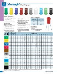
Solid stream nozzles, offered in both single- and multiple-stream<br />
versions, are designed to deliver fertilizer to the soil surface where<br />
it can be effectively utilized by the crop. By creating solid liquid<br />
streams, these nozzles greatly reduce foliar coverage in standing<br />
crop in order to minimize leaf burn. TeeJet Technologies StreamJet<br />
nozzles provide the ideal blend of compact, reliable design, ease of<br />
installation and affordable pricing.<br />
(3-ORIFICE)<br />
Reference page 42<br />
very GOOD<br />
EXCELLENT<br />
In some cases, the use of a broadcast nozzle for fertilizer application<br />
may be desirable. This could include combined fertilizer/pesticide<br />
applications, foliar feeding or broadcast liquid fertilization of bare<br />
ground. For these applications TeeJet Technologies offers a wide<br />
variety of low drift, flat spray nozzles.<br />
(Single-ORIFICE)<br />
Reference page 45<br />
EXCELLENT<br />
Liquid Density Conversion<br />
CP4916<br />
(ORIFICE PLATE)<br />
Reference page 44<br />
EXCELLENT<br />
When selecting a specific capacity tip for liquid fertilizer application,<br />
always correct for liquid density. Application charts shown in this<br />
catalog are based on spraying water. Many fertilizer solutions are<br />
denser than water, which will affect the application rate. Please see<br />
page 125 for a list of density conversion factors.<br />
(LARGE CAPACITY)<br />
Reference page 12<br />
very GOOD<br />
Example:<br />
Desired application rate is 20 GPA of 28% Nitrogen. Determine the<br />
correct nozzle size as follow:<br />
(LOW VOLUME)<br />
Reference pages 7–8<br />
very GOOD<br />
GPA (liquid other than water) x Conversion Factor = GPA (from table<br />
in catalog)<br />
20 GPA (28%) x 1.13 = 22.6 GPA (water)<br />
(LOW VOLUME)<br />
Reference page 33<br />
very GOOD<br />
The applicator should choose a nozzle size that will supply 22.6 GPA<br />
of water at the desired pressure.<br />
Reference page 9<br />
EXCELLENT<br />
Reference page 19<br />
EXCELLENT<br />
Reference page 21<br />
EXCELLENT<br />
Note: Consult the chemical manufacturer’s product label for specific rate and application recommendations.<br />
4<br />
SELECTION GUIDE
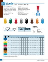
Wide Angle Flat Spray Tips<br />
Typical Applications:<br />
See selection guide on page 2 for<br />
recommended typical applications<br />
for Turbo TeeJet tips.<br />
Features:<br />
n Tapered edge wide angle flat spray pattern<br />
for uniform coverage in broadcast spraying.<br />
n Large, rounded internal passage to<br />
minimize clogging.<br />
n Excellent resistance to corrosive solutions.<br />
n Superior wear characteristics.<br />
n Larger droplets for less drift—<br />
15–90 PSI (1–6 bar).<br />
n Automatic spray alignment with 25612-*-NYR<br />
Quick TeeJet® cap and gasket. Reference page<br />
57 for more information.<br />
n Blockage-free passage means less clogging.<br />
n Unique internal configuration means<br />
substantially longer wear life.<br />
TT11001<br />
(100)<br />
TT110015<br />
(100)<br />
TT11002<br />
(50)<br />
TT110025<br />
(50)<br />
TT11003<br />
(50)<br />
TT11004<br />
(50)<br />
TT11005<br />
(50)<br />
TT11006<br />
(50)<br />
TT11008<br />
(50)<br />
psi<br />
Drop<br />
Size<br />
capacity<br />
one<br />
nozzle<br />
in GPM<br />
capacity<br />
one<br />
nozzle<br />
in<br />
oz./min.<br />
gpa<br />
209<br />
gallons per 1000 sq. ft.<br />
4 mph 5 mph 6 mph 8 mph 10 mph 12 mph 15 mph 20 mph 2 mph 3 mph 4 mph 5 mph<br />
15 C 0.061 7.8 4.5 3.6 3.0 2.3 1.8 1.5 1.2 0.91 0.21 0.14 0.10 0.08<br />
20 M 0.071 9.1 5.3 4.2 3.5 2.6 2.1 1.8 1.4 1.1 0.24 0.16 0.12 0.10<br />
30 M 0.087 11 6.5 5.2 4.3 3.2 2.6 2.2 1.7 1.3 0.30 0.20 0.15 0.12<br />
40 M 0.10 13 7.4 5.9 5.0 3.7 3.0 2.5 2.0 1.5 0.34 0.23 0.17 0.14<br />
50 F 0.11 14 8.2 6.5 5.4 4.1 3.3 2.7 2.2 1.6 0.37 0.25 0.19 0.15<br />
60 F 0.12 15 8.9 7.1 5.9 4.5 3.6 3.0 2.4 1.8 0.41 0.27 0.20 0.16<br />
75 F 0.14 18 10.4 8.3 6.9 5.2 4.2 3.5 2.8 2.1 0.48 0.32 0.24 0.19<br />
90 F 0.15 19 11.1 8.9 7.4 5.6 4.5 3.7 3.0 2.2 0.<strong>51</strong> 0.34 0.26 0.20<br />
15 C 0.092 12 6.8 5.5 4.6 3.4 2.7 2.3 1.8 1.4 0.31 0.21 0.16 0.13<br />
20 C 0.11 14 8.2 6.5 5.4 4.1 3.3 2.7 2.2 1.6 0.37 0.25 0.19 0.15<br />
30 M 0.13 17 9.7 7.7 6.4 4.8 3.9 3.2 2.6 1.9 0.44 0.29 0.22 0.18<br />
40 M 0.15 19 11.1 8.9 7.4 5.6 4.5 3.7 3.0 2.2 0.<strong>51</strong> 0.34 0.26 0.20<br />
50 M 0.17 22 12.6 10.1 8.4 6.3 5.0 4.2 3.4 2.5 0.58 0.39 0.29 0.23<br />
60 M 0.18 23 13.4 10.7 8.9 6.7 5.3 4.5 3.6 2.7 0.61 0.41 0.31 0.24<br />
75 F 0.21 27 15.6 12.5 10.4 7.8 6.2 5.2 4.2 3.1 0.71 0.48 0.36 0.29<br />
90 F 0.23 29 17.1 13.7 11.4 8.5 6.8 5.7 4.6 3.4 0.78 0.52 0.39 0.31<br />
15 C 0.12 15 8.9 7.1 5.9 4.5 3.6 3.0 2.4 1.8 0.41 0.27 0.20 0.16<br />
20 C 0.14 18 10.4 8.3 6.9 5.2 4.2 3.5 2.8 2.1 0.48 0.32 0.24 0.19<br />
30 M 0.17 22 12.6 10.1 8.4 6.3 5.0 4.2 3.4 2.5 0.58 0.39 0.29 0.23<br />
40 M 0.20 26 14.9 11.9 9.9 7.4 5.9 5.0 4.0 3.0 0.68 0.45 0.34 0.27<br />
50 M 0.22 28 16.3 13.1 10.9 8.2 6.5 5.4 4.4 3.3 0.75 0.50 0.37 0.30<br />
60 M 0.24 31 17.8 14.3 11.9 8.9 7.1 5.9 4.8 3.6 0.82 0.54 0.41 0.33<br />
75 M 0.27 35 20 16.0 13.4 10.0 8.0 6.7 5.3 4.0 0.92 0.61 0.46 0.37<br />
90 F 0.30 38 22 17.8 14.9 11.1 8.9 7.4 5.9 4.5 1.0 0.68 0.<strong>51</strong> 0.41<br />
15 VC 0.15 19 11.1 8.9 7.4 5.6 4.5 3.7 3.0 2.2 0.<strong>51</strong> 0.34 0.26 0.20<br />
20 C 0.18 23 13.4 10.7 8.9 6.7 5.3 4.5 3.6 2.7 0.61 0.41 0.31 0.24<br />
30 C 0.22 28 16.3 13.1 10.9 8.2 6.5 5.4 4.4 3.3 0.75 0.50 0.37 0.30<br />
40 M 0.25 32 18.6 14.9 12.4 9.3 7.4 6.2 5.0 3.7 0.85 0.57 0.43 0.34<br />
50 M 0.28 36 21 16.6 13.9 10.4 8.3 6.9 5.5 4.2 0.95 0.63 0.48 0.38<br />
60 M 0.31 40 23 18.4 15.3 11.5 9.2 7.7 6.1 4.6 1.1 0.70 0.53 0.42<br />
75 M 0.34 44 25 20 16.8 12.6 10.1 8.4 6.7 5.0 1.2 0.77 0.58 0.46<br />
90 F 0.38 49 28 23 18.8 14.1 11.3 9.4 7.5 5.6 1.3 0.86 0.65 0.52<br />
15 VC 0.18 23 13.4 10.7 8.9 6.7 5.3 4.5 3.6 2.7 0.61 0.41 0.31 0.24<br />
20 VC 0.21 27 15.6 12.5 10.4 7.8 6.2 5.2 4.2 3.1 0.71 0.48 0.36 0.29<br />
30 C 0.26 33 19.3 15.4 12.9 9.7 7.7 6.4 5.1 3.9 0.88 0.59 0.44 0.35<br />
40 C 0.30 38 22 17.8 14.9 11.1 8.9 7.4 5.9 4.5 1.0 0.68 0.<strong>51</strong> 0.41<br />
50 M 0.34 44 25 20 16.8 12.6 10.1 8.4 6.7 5.0 1.2 0.77 0.58 0.46<br />
60 M 0.37 47 27 22 18.3 13.7 11.0 9.2 7.3 5.5 1.3 0.84 0.63 0.50<br />
75 M 0.41 52 30 24 20 15.2 12.2 10.1 8.1 6.1 1.4 0.93 0.70 0.56<br />
90 M 0.45 58 33 27 22 16.7 13.4 11.1 8.9 6.7 1.5 1.0 0.77 0.61<br />
15 XC 0.24 31 17.8 14.3 11.9 8.9 7.1 5.9 4.8 3.6 0.82 0.54 0.41 0.33<br />
20 VC 0.28 36 21 16.6 13.9 10.4 8.3 6.9 5.5 4.2 0.95 0.63 0.48 0.38<br />
30 C 0.35 45 26 21 17.3 13.0 10.4 8.7 6.9 5.2 1.2 0.79 0.60 0.48<br />
40 C 0.40 <strong>51</strong> 30 24 19.8 14.9 11.9 9.9 7.9 5.9 1.4 0.91 0.68 0.54<br />
50 C 0.45 58 33 27 22 16.7 13.4 11.1 8.9 6.7 1.5 1.0 0.77 0.61<br />
60 C 0.49 63 36 29 24 18.2 14.6 12.1 9.7 7.3 1.7 1.1 0.83 0.67<br />
75 M 0.55 70 41 33 27 20 16.3 13.6 10.9 8.2 1.9 1.2 0.94 0.75<br />
90 M 0.60 77 45 36 30 22 17.8 14.9 11.9 8.9 2.0 1.4 1.0 0.82<br />
15 XC 0.31 40 23 18.4 15.3 11.5 9.2 7.7 6.1 4.6 1.1 0.70 0.53 0.42<br />
20 VC 0.35 45 26 21 17.3 13.0 10.4 8.7 6.9 5.2 1.2 0.79 0.60 0.48<br />
30 VC 0.43 55 32 26 21 16.0 12.8 10.6 8.5 6.4 1.5 0.97 0.73 0.58<br />
40 C 0.50 64 37 30 25 18.6 14.9 12.4 9.9 7.4 1.7 1.1 0.85 0.68<br />
50 C 0.56 72 42 33 28 21 16.6 13.9 11.1 8.3 1.9 1.3 0.95 0.76<br />
60 C 0.61 78 45 36 30 23 18.1 15.1 12.1 9.1 2.1 1.4 1.0 0.83<br />
75 C 0.68 87 50 40 34 25 20 16.8 13.5 10.1 2.3 1.5 1.2 0.92<br />
90 M 0.75 96 56 45 37 28 22 18.6 14.9 11.1 2.6 1.7 1.3 1.0<br />
15 XC 0.37 47 27 22 18.3 13.7 11.0 9.2 7.3 5.5 1.3 0.84 0.63 0.50<br />
20 XC 0.42 54 31 25 21 15.6 12.5 10.4 8.3 6.2 1.4 0.95 0.71 0.57<br />
30 VC 0.52 67 39 31 26 19.3 15.4 12.9 10.3 7.7 1.8 1.2 0.88 0.71<br />
40 C 0.60 77 45 36 30 22 17.8 14.9 11.9 8.9 2.0 1.4 1.0 0.82<br />
50 C 0.67 86 50 40 33 25 19.9 16.6 13.3 9.9 2.3 1.5 1.1 0.91<br />
60 C 0.73 93 54 43 36 27 22 18.1 14.5 10.8 2.5 1.7 1.2 0.99<br />
75 C 0.82 105 61 49 41 30 24 20 16.2 12.2 2.8 1.9 1.4 1.1<br />
90 M 0.90 115 67 53 45 33 27 22 17.8 13.4 3.1 2.0 1.5 1.2<br />
15 XC 0.49 63 36 29 24 18.2 14.6 12.1 9.7 7.3 1.7 1.1 0.83 0.67<br />
20 XC 0.57 73 42 34 28 21 16.9 14.1 11.3 8.5 1.9 1.3 0.97 0.78<br />
30 VC 0.69 88 <strong>51</strong> 41 34 26 20 17.1 13.7 10.2 2.3 1.6 1.2 0.94<br />
40 VC 0.80 102 59 48 40 30 24 19.8 15.8 11.9 2.7 1.8 1.4 1.1<br />
50 C 0.89 114 66 53 44 33 26 22 17.6 13.2 3.0 2.0 1.5 1.2<br />
60 C 0.98 125 73 58 49 36 29 24 19.4 14.6 3.3 2.2 1.7 1.3<br />
75 C 1.10 141 82 65 54 41 33 27 22 16.3 3.7 2.5 1.9 1.5<br />
90 M 1.20 154 89 71 59 45 36 30 24 17.8 4.1 2.7 2.0 1.6<br />
Note: Always double check your application rates. Tabulations are based on spraying water at 70°F (21°C).<br />
See pages 124–140 for drop size classification, useful formulas and other information.<br />
BROADCAST NOZZLES<br />
CONTACT<br />
Product<br />
Spacing<br />
110°<br />
SYSTEMIC<br />
Product<br />
Optimum Spray Height<br />
DRIFT<br />
Management<br />
Very Good Very Good Very Good<br />
Good* EXCELLENT* Very Good*<br />
*At pressures below 30 PSI (2.0 bar)<br />
209<br />
209<br />
How to order:<br />
Specify tip number.<br />
Example:<br />
TT11001-VP – Polymer with VisiFlo®<br />
color-coding<br />
Spray<br />
Height<br />
5
Air Induction XR Flat Spray Tips<br />
Typical Applications:<br />
See selection guide on page 2 for<br />
recommended typical applications<br />
for AIXR TeeJet tips.<br />
Features:<br />
n 110° wide, tapered flat spray angle with<br />
air induction technology offers better<br />
drift management.<br />
n Made of a two-piece UHMWPE polymer<br />
construction with VisiFlo® color-coding.<br />
UHMPE provides excellent chemical<br />
resistance, including acids, as well as<br />
exceptional wear life.<br />
n Compact size to prevent tip damage.<br />
n Depending on the chemical, produces<br />
large air-filled drops through a Venturi<br />
air aspirator.<br />
n Removable pre-orifice.<br />
n Available in seven tip capacities with<br />
a wide operating pressure range:<br />
15–90 PSI (1–6 bar).<br />
n Automatic alignment when used with<br />
25612-*-NYR Quick TeeJet® cap and gasket.<br />
Reference page 57 for more information.<br />
Chamfer<br />
Removable<br />
Pre-Orifice<br />
O-Ring<br />
AIXR110015<br />
(100)<br />
AIXR11002<br />
(50)<br />
AIXR110025<br />
(50)<br />
AIXR11003<br />
(50)<br />
AIXR11004<br />
(50)<br />
AIXR11005<br />
(50)<br />
AIXR11006<br />
(50)<br />
psi<br />
Drop<br />
Size<br />
capacity<br />
capacity<br />
one<br />
one<br />
nozzle<br />
nozzle<br />
in<br />
in GPM<br />
oz./min.<br />
gpa<br />
209<br />
gallons per 1000 sq. ft.<br />
4 mph 5 mph 6 mph 8 mph 10 mph 12 mph 15 mph 20 mph 2 mph 3 mph 4 mph 5 mph<br />
15 XC 0.092 12 6.8 5.5 4.6 3.4 2.7 2.3 1.8 1.4 0.31 0.21 0.16 0.13<br />
20 XC 0.11 14 8.2 6.5 5.4 4.1 3.3 2.7 2.2 1.6 0.37 0.25 0.19 0.15<br />
30 C 0.13 17 9.7 7.7 6.4 4.8 3.9 3.2 2.6 1.9 0.44 0.29 0.22 0.18<br />
40 C 0.15 19 11.1 8.9 7.4 5.6 4.5 3.7 3.0 2.2 0.<strong>51</strong> 0.34 0.26 0.20<br />
50 C 0.17 22 12.6 10.1 8.4 6.3 5.0 4.2 3.4 2.5 0.58 0.39 0.29 0.23<br />
60 M 0.18 23 13.4 10.7 8.9 6.7 5.3 4.5 3.6 2.7 0.61 0.41 0.31 0.24<br />
80 M 0.21 27 15.6 12.5 10.4 7.8 6.2 5.2 4.2 3.1 0.71 0.48 0.36 0.29<br />
90 M 0.23 29 17.1 13.7 11.4 8.5 6.8 5.7 4.6 3.4 0.78 0.52 0.39 0.31<br />
15 XC 0.12 15 8.9 7.1 5.9 4.5 3.6 3.0 2.4 1.8 0.41 0.27 0.20 0.16<br />
20 XC 0.14 18 10.4 8.3 6.9 5.2 4.2 3.5 2.8 2.1 0.48 0.32 0.24 0.19<br />
30 VC 0.17 22 12.6 10.1 8.4 6.3 5.0 4.2 3.4 2.5 0.58 0.39 0.29 0.23<br />
40 C 0.20 26 14.9 11.9 9.9 7.4 5.9 5.0 4.0 3.0 0.68 0.45 0.34 0.27<br />
50 C 0.22 28 16.3 13.1 10.9 8.2 6.5 5.4 4.4 3.3 0.75 0.50 0.37 0.30<br />
60 C 0.24 31 17.8 14.3 11.9 8.9 7.1 5.9 4.8 3.6 0.82 0.54 0.41 0.33<br />
80 M 0.27 35 20 16.0 13.4 10.0 8.0 6.7 5.3 4.0 0.92 0.61 0.46 0.37<br />
90 M 0.30 38 22 17.8 14.9 11.1 8.9 7.4 5.9 4.5 1.0 0.68 0.<strong>51</strong> 0.41<br />
15 XC 0.15 19 11.1 8.9 7.4 5.6 4.5 3.7 3.0 2.2 0.<strong>51</strong> 0.34 0.26 0.20<br />
20 XC 0.18 23 13.4 10.7 8.9 6.7 5.3 4.5 3.6 2.7 0.61 0.41 0.31 0.24<br />
30 XC 0.22 28 16.3 13.1 10.9 8.2 6.5 5.4 4.4 3.3 0.75 0.50 0.37 0.30<br />
40 VC 0.25 32 18.6 14.9 12.4 9.3 7.4 6.2 5.0 3.7 0.85 0.57 0.43 0.34<br />
50 C 0.28 36 21 16.6 13.9 10.4 8.3 6.9 5.5 4.2 0.95 0.63 0.48 0.38<br />
60 C 0.31 40 23 18.4 15.3 11.5 9.2 7.7 6.1 4.6 1.1 0.70 0.53 0.42<br />
80 C 0.34 44 25 20 16.8 12.6 10.1 8.4 6.7 5.0 1.2 0.77 0.58 0.46<br />
90 C 0.38 49 28 23 18.8 14.1 11.3 9.4 7.5 5.6 1.3 0.86 0.65 0.52<br />
15 XC 0.18 23 13.4 10.7 8.9 6.7 5.3 4.5 3.6 2.7 0.61 0.41 0.31 0.24<br />
20 XC 0.21 27 15.6 12.5 10.4 7.8 6.2 5.2 4.2 3.1 0.71 0.48 0.36 0.29<br />
30 XC 0.26 33 19.3 15.4 12.9 9.7 7.7 6.4 5.1 3.9 0.88 0.59 0.44 0.35<br />
40 VC 0.30 38 22 17.8 14.9 11.1 8.9 7.4 5.9 4.5 1.0 0.68 0.<strong>51</strong> 0.41<br />
50 C 0.34 44 25 20 16.8 12.6 10.1 8.4 6.7 5.0 1.2 0.77 0.58 0.46<br />
60 C 0.37 47 27 22 18.3 13.7 11.0 9.2 7.3 5.5 1.3 0.84 0.63 0.50<br />
80 C 0.41 52 30 24 20 15.2 12.2 10.1 8.1 6.1 1.4 0.93 0.70 0.56<br />
90 C 0.45 58 33 27 22 16.7 13.4 11.1 8.9 6.7 1.5 1.0 0.77 0.61<br />
15 UC 0.24 31 17.8 14.3 11.9 8.9 7.1 5.9 4.8 3.6 0.82 0.54 0.41 0.33<br />
20 XC 0.28 36 21 16.6 13.9 10.4 8.3 6.9 5.5 4.2 0.95 0.63 0.48 0.38<br />
30 XC 0.35 45 26 21 17.3 13.0 10.4 8.7 6.9 5.2 1.2 0.79 0.60 0.48<br />
40 XC 0.40 <strong>51</strong> 30 24 19.8 14.9 11.9 9.9 7.9 5.9 1.4 0.91 0.68 0.54<br />
50 VC 0.45 58 33 27 22 16.7 13.4 11.1 8.9 6.7 1.5 1.0 0.77 0.61<br />
60 VC 0.49 63 36 29 24 18.2 14.6 12.1 9.7 7.3 1.7 1.1 0.83 0.67<br />
80 C 0.55 70 41 33 27 20 16.3 13.6 10.9 8.2 1.9 1.2 0.94 0.75<br />
90 C 0.60 77 45 36 30 22 17.8 14.9 11.9 8.9 2.0 1.4 1.0 0.82<br />
15 UC 0.31 40 23 18.4 15.3 11.5 9.2 7.7 6.1 4.6 1.1 0.70 0.53 0.42<br />
20 XC 0.35 45 26 21 17.3 13.0 10.4 8.7 6.9 5.2 1.2 0.79 0.60 0.48<br />
30 XC 0.43 55 32 26 21 16.0 12.8 10.6 8.5 6.4 1.5 0.97 0.73 0.58<br />
40 XC 0.50 64 37 30 25 18.6 14.9 12.4 9.9 7.4 1.7 1.1 0.85 0.68<br />
50 VC 0.56 72 42 33 28 21 16.6 13.9 11.1 8.3 1.9 1.3 0.95 0.76<br />
60 VC 0.61 78 45 36 30 23 18.1 15.1 12.1 9.1 2.1 1.4 1.0 0.83<br />
80 C 0.68 87 50 40 34 25 20 16.8 13.5 10.1 2.3 1.5 1.2 0.92<br />
90 C 0.75 96 56 45 37 28 22 18.6 14.9 11.1 2.6 1.7 1.3 1.0<br />
15 UC 0.37 47 27 22 18.3 13.7 11.0 9.2 7.3 5.5 1.3 0.84 0.63 0.50<br />
20 XC 0.42 54 31 25 21 15.6 12.5 10.4 8.3 6.2 1.4 0.95 0.71 0.57<br />
30 XC 0.52 67 39 31 26 19.3 15.4 12.9 10.3 7.7 1.8 1.2 0.88 0.71<br />
40 XC 0.60 77 45 36 30 22 17.8 14.9 11.9 8.9 2.0 1.4 1.0 0.82<br />
50 VC 0.67 86 50 40 33 25 19.9 16.6 13.3 9.9 2.3 1.5 1.1 0.91<br />
60 VC 0.73 93 54 43 36 27 22 18.1 14.5 10.8 2.5 1.7 1.2 0.99<br />
80 C 0.82 105 61 49 41 30 24 20 16.2 12.2 2.8 1.9 1.4 1.1<br />
90 C 0.90 115 67 53 45 33 27 22 17.8 13.4 3.1 2.0 1.5 1.2<br />
Note: Always double check your application rates. Tabulations are based on spraying water at 70°F (21°C).<br />
See pages 124–140 for drop size classification, useful formulas and other information.<br />
Air Inlet<br />
Exit<br />
Orfice<br />
CONTACT<br />
Product<br />
AIXR110___-VP Spray Tip<br />
(Cross Section View)<br />
Spacing<br />
Optimum Spray Height<br />
110°<br />
SYSTEMIC<br />
Product<br />
Air Inlet<br />
DRIFT<br />
Management<br />
Good EXCELLENT EXCELLENT<br />
209<br />
209<br />
Spray<br />
Height<br />
How to order:<br />
Specify tip number.<br />
Example:<br />
AIXR11004VP – Polymer with<br />
VisiFlo color-coding<br />
6<br />
BROADCAST NOZZLES
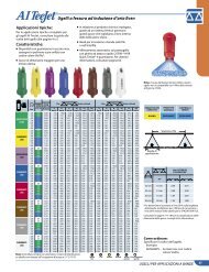
Air Induction Flat Spray Tips<br />
Typical Applications:<br />
See selection guide on page 2 for<br />
recommended typical applications<br />
for AI TeeJet tips.<br />
Features:<br />
n Stainless steel insert produces a tapered<br />
edge flat spray pattern for uniform<br />
coverage in broadcast spraying.<br />
n Polymer insert holder and pre-orifice<br />
with VisiFlo® color-coding.<br />
n Larger droplets for less drift.<br />
n Available in eight capacities with<br />
a recommended pressure rating<br />
30–115 PSI (2–8 bar).<br />
n Depending on the chemical, produces<br />
large air-filled drops through the use<br />
of a Venturi air aspirator.<br />
n Automatic spray alignment with<br />
25598-*-NYR Quick TeeJet® cap<br />
and gasket. Reference page 57<br />
for more information.<br />
AI80015<br />
AI110015<br />
(100)<br />
AI8002<br />
AI11002<br />
(50)<br />
AI80025<br />
AI110025<br />
(50)<br />
AI8003<br />
AI11003<br />
(50)<br />
AI8004<br />
AI11004<br />
(50)<br />
AI8005<br />
AI11005<br />
(50)<br />
AI8006<br />
AI11006<br />
(50)<br />
AI11008<br />
(50)<br />
capacity<br />
Drop capacity<br />
one<br />
209<br />
Size one<br />
nozzle<br />
nozzle<br />
psi<br />
in<br />
gpa<br />
gallons per 1000 sq. ft.<br />
in GPM<br />
110º oz./min. 4 mph 5 mph 6 mph 8 mph 10 mph 12 mph 15 mph 20 mph 2 mph 3 mph 4 mph 5 mph<br />
30 UC 0.13 17 9.7 7.7 6.4 4.8 3.9 3.2 2.6 1.9 0.44 0.29 0.22 0.18<br />
40 XC 0.15 19 11.1 8.9 7.4 5.6 4.5 3.7 3.0 2.2 0.<strong>51</strong> 0.34 0.26 0.20<br />
50 XC 0.17 22 12.6 10.1 8.4 6.3 5.0 4.2 3.4 2.5 0.58 0.39 0.29 0.23<br />
60 VC 0.18 23 13.4 10.7 8.9 6.7 5.3 4.5 3.6 2.7 0.61 0.41 0.31 0.24<br />
70 VC 0.20 26 14.9 11.9 9.9 7.4 5.9 5.0 4.0 3.0 0.68 0.45 0.34 0.27<br />
80 VC 0.21 27 15.6 12.5 10.4 7.8 6.2 5.2 4.2 3.1 0.71 0.48 0.36 0.29<br />
90 C 0.23 29 17.1 13.7 11.4 8.5 6.8 5.7 4.6 3.4 0.78 0.52 0.39 0.31<br />
100 C 0.24 31 17.8 14.3 11.9 8.9 7.1 5.9 4.8 3.6 0.82 0.54 0.41 0.33<br />
30 UC 0.17 22 12.6 10.1 8.4 6.3 5.0 4.2 3.4 2.5 0.58 0.39 0.29 0.23<br />
40 XC 0.20 26 14.9 11.9 9.9 7.4 5.9 5.0 4.0 3.0 0.68 0.45 0.34 0.27<br />
50 XC 0.22 28 16.3 13.1 10.9 8.2 6.5 5.4 4.4 3.3 0.75 0.50 0.37 0.30<br />
60 VC 0.24 31 17.8 14.3 11.9 8.9 7.1 5.9 4.8 3.6 0.82 0.54 0.41 0.33<br />
70 VC 0.26 33 19.3 15.4 12.9 9.7 7.7 6.4 5.1 3.9 0.88 0.59 0.44 0.35<br />
80 VC 0.28 36 21 16.6 13.9 10.4 8.3 6.9 5.5 4.2 0.95 0.63 0.48 0.38<br />
90 VC 0.30 38 22 17.8 14.9 11.1 8.9 7.4 5.9 4.5 1.0 0.68 0.<strong>51</strong> 0.41<br />
100 C 0.32 41 24 19.0 15.8 11.9 9.5 7.9 6.3 4.8 1.1 0.73 0.54 0.44<br />
30 UC 0.22 28 16.3 13.1 10.9 8.2 6.5 5.4 4.4 3.3 0.75 0.50 0.37 0.30<br />
40 XC 0.25 32 18.6 14.9 12.4 9.3 7.4 6.2 5.0 3.7 0.85 0.57 0.43 0.34<br />
50 XC 0.28 36 21 16.6 13.9 10.4 8.3 6.9 5.5 4.2 0.95 0.63 0.48 0.38<br />
60 XC 0.31 40 23 18.4 15.3 11.5 9.2 7.7 6.1 4.6 1.1 0.70 0.53 0.42<br />
70 VC 0.33 42 25 19.6 16.3 12.3 9.8 8.2 6.5 4.9 1.1 0.75 0.56 0.45<br />
80 VC 0.35 45 26 21 17.3 13.0 10.4 8.7 6.9 5.2 1.2 0.79 0.60 0.48<br />
90 VC 0.38 49 28 23 18.8 14.1 11.3 9.4 7.5 5.6 1.3 0.86 0.65 0.52<br />
100 C 0.40 <strong>51</strong> 30 24 19.8 14.9 11.9 9.9 7.9 5.9 1.4 0.91 0.68 0.54<br />
30 UC 0.26 33 19.3 15.4 12.9 9.7 7.7 6.4 5.1 3.9 0.88 0.59 0.44 0.35<br />
40 XC 0.30 38 22 17.8 14.9 11.1 8.9 7.4 5.9 4.5 1.0 0.68 0.<strong>51</strong> 0.41<br />
50 XC 0.34 44 25 20 16.8 12.6 10.1 8.4 6.7 5.0 1.2 0.77 0.58 0.46<br />
60 XC 0.37 47 27 22 18.3 13.7 11.0 9.2 7.3 5.5 1.3 0.84 0.63 0.50<br />
70 VC 0.40 <strong>51</strong> 30 24 19.8 14.9 11.9 9.9 7.9 5.9 1.4 0.91 0.68 0.54<br />
80 VC 0.42 54 31 25 21 15.6 12.5 10.4 8.3 6.2 1.4 0.95 0.71 0.57<br />
90 VC 0.45 58 33 27 22 16.7 13.4 11.1 8.9 6.7 1.5 1.0 0.77 0.61<br />
100 C 0.47 60 35 28 23 17.4 14.0 11.6 9.3 7.0 1.6 1.1 0.80 0.64<br />
30 UC 0.35 45 26 21 17.3 13.0 10.4 8.7 6.9 5.2 1.2 0.79 0.60 0.48<br />
40 XC 0.40 <strong>51</strong> 30 24 19.8 14.9 11.9 9.9 7.9 5.9 1.4 0.91 0.68 0.54<br />
50 XC 0.45 58 33 27 22 16.7 13.4 11.1 8.9 6.7 1.5 1.0 0.77 0.61<br />
60 XC 0.49 63 36 29 24 18.2 14.6 12.1 9.7 7.3 1.7 1.1 0.83 0.67<br />
70 VC 0.53 68 39 31 26 19.7 15.7 13.1 10.5 7.9 1.8 1.2 0.90 0.72<br />
80 VC 0.57 73 42 34 28 21 16.9 14.1 11.3 8.5 1.9 1.3 0.97 0.78<br />
90 VC 0.60 77 45 36 30 22 17.8 14.9 11.9 8.9 2.0 1.4 1.0 0.82<br />
100 C 0.63 81 47 37 31 23 18.7 15.6 12.5 9.4 2.1 1.4 1.1 0.86<br />
30 UC 0.43 55 32 26 21 16.0 12.8 10.6 8.5 6.4 1.5 0.97 0.73 0.58<br />
40 XC 0.50 64 37 30 25 18.6 14.9 12.4 9.9 7.4 1.7 1.1 0.85 0.68<br />
50 XC 0.56 72 42 33 28 21 16.6 13.9 11.1 8.3 1.9 1.3 0.95 0.76<br />
60 XC 0.61 78 45 36 30 23 18.1 15.1 12.1 9.1 2.1 1.4 1.0 0.83<br />
70 VC 0.66 84 49 39 33 25 19.6 16.3 13.1 9.8 2.2 1.5 1.1 0.90<br />
80 VC 0.71 91 53 42 35 26 21 17.6 14.1 10.5 2.4 1.6 1.2 0.97<br />
90 VC 0.75 96 56 45 37 28 22 18.6 14.9 11.1 2.6 1.7 1.3 1.0<br />
100 VC 0.79 101 59 47 39 29 23 19.6 15.6 11.7 2.7 1.8 1.3 1.1<br />
30 UC 0.52 67 39 31 26 19.3 15.4 12.9 10.3 7.7 1.8 1.2 0.88 0.71<br />
40 UC 0.60 77 45 36 30 22 17.8 14.9 11.9 8.9 2.0 1.4 1.0 0.82<br />
50 XC 0.67 86 50 40 33 25 19.9 16.6 13.3 9.9 2.3 1.5 1.1 0.91<br />
60 XC 0.73 93 54 43 36 27 22 18.1 14.5 10.8 2.5 1.7 1.2 0.99<br />
70 XC 0.79 101 59 47 39 29 23 19.6 15.6 11.7 2.7 1.8 1.3 1.1<br />
80 VC 0.85 109 63 50 42 32 25 21 16.8 12.6 2.9 1.9 1.4 1.2<br />
90 VC 0.90 115 67 53 45 33 27 22 17.8 13.4 3.1 2.0 1.5 1.2<br />
100 VC 0.95 122 71 56 47 35 28 24 18.8 14.1 3.2 2.2 1.6 1.3<br />
30 UC 0.69 88 <strong>51</strong> 41 34 26 20 17.1 13.7 10.2 2.3 1.6 1.2 0.94<br />
40 UC 0.80 102 59 48 40 30 24 19.8 15.8 11.9 2.7 1.8 1.4 1.1<br />
50 XC 0.89 114 66 53 44 33 26 22 17.6 13.2 3.0 2.0 1.5 1.2<br />
60 XC 0.98 125 73 58 49 36 29 24 19.4 14.6 3.3 2.2 1.7 1.3<br />
70 XC 1.06 136 79 63 52 39 31 26 21 15.7 3.6 2.4 1.8 1.4<br />
80 VC 1.13 145 84 67 56 42 34 28 22 16.8 3.8 2.6 1.9 1.5<br />
90 VC 1.20 154 89 71 59 45 36 30 24 17.8 4.1 2.7 2.0 1.6<br />
100 VC 1.26 161 94 75 62 47 37 31 25 18.7 4.3 2.9 2.1 1.7<br />
Note: Always double check your application rates. Tabulations are based on spraying water at 70°F (21°C).<br />
See pages 124–140 for drop size classification, useful formulas and other information.<br />
Note: Due to the pre-orifice design,<br />
this tip is not compatible with the<br />
4193A check valve tip strainer.<br />
CONTACT<br />
Product<br />
Spacing<br />
80°<br />
110°<br />
SYSTEMIC<br />
Product<br />
DRIFT<br />
Management<br />
Good EXCELLENT EXCELLENT<br />
Optimum Spray Height<br />
209<br />
309<br />
209<br />
Spray<br />
Height<br />
How to order:<br />
Specify tip number.<br />
Example:<br />
AI11004-VS – Stainless Steel with<br />
VisiFlo color-coding<br />
BROADCAST NOZZLES<br />
7<br />
7
Air Induction Flat Spray Tips<br />
Typical Applications:<br />
See selection guide on page 2 for<br />
recommended typical applications<br />
for AIC TeeJet tips.<br />
Features:<br />
n Produces a 110° tapered edge flat<br />
spray pattern for uniform coverage<br />
in broadcast spraying applications.<br />
n Available with a polymer insert<br />
holder with stainless steel<br />
(015–15 capacities), ceramic<br />
(025–05 capacities) or polymer<br />
(02–10 capacities) inserts.<br />
n Larger droplets for less drift.<br />
n Depending on the chemical,<br />
produces large air-filled drops<br />
through the use of a Venturi air<br />
aspirator.<br />
n AI TeeJet nozzle molded into<br />
Quick TeeJet® cap provides<br />
automatic spray alignment.<br />
n <strong>Inc</strong>ludes tightly fitting washer<br />
that stays put and assures a<br />
good seal.<br />
n Recommended pressure rating<br />
30–115 PSI (2–8 bar).<br />
8<br />
AIC110015<br />
(100)<br />
AIC11002<br />
(50)<br />
AIC110025<br />
(50)<br />
AIC11003<br />
(50)<br />
AIC11004<br />
(50)<br />
AIC11005<br />
(50)<br />
AIC11006<br />
(50)<br />
AIC11008<br />
(50)<br />
AIC11010<br />
AIC11015<br />
psi<br />
Drop<br />
Size<br />
capacity<br />
one<br />
nozzle<br />
in GPM<br />
capacity<br />
one<br />
nozzle<br />
in<br />
oz./min.<br />
gpa<br />
209<br />
gallons per 1000 sq. ft.<br />
4 mph 5 mph 6 mph 8 mph 10 mph 12 mph 15 mph 20 mph 2 mph 3 mph 4 mph 5 mph<br />
30 UC 0.13 17 9.7 7.7 6.4 4.8 3.9 3.2 2.6 1.9 0.44 0.29 0.22 0.18<br />
40 XC 0.15 19 11.1 8.9 7.4 5.6 4.5 3.7 3.0 2.2 0.<strong>51</strong> 0.34 0.26 0.20<br />
50 XC 0.17 22 12.6 10.1 8.4 6.3 5.0 4.2 3.4 2.5 0.58 0.39 0.29 0.23<br />
60 VC 0.18 23 13.4 10.7 8.9 6.7 5.3 4.5 3.6 2.7 0.61 0.41 0.31 0.24<br />
70 VC 0.20 26 14.9 11.9 9.9 7.4 5.9 5.0 4.0 3.0 0.68 0.45 0.34 0.27<br />
80 VC 0.21 27 15.6 12.5 10.4 7.8 6.2 5.2 4.2 3.1 0.71 0.48 0.36 0.29<br />
90 C 0.23 29 17.1 13.7 11.4 8.5 6.8 5.7 4.6 3.4 0.78 0.52 0.39 0.31<br />
100 C 0.24 31 17.8 14.3 11.9 8.9 7.1 5.9 4.8 3.6 0.82 0.54 0.41 0.33<br />
30 UC 0.17 22 12.6 10.1 8.4 6.3 5.0 4.2 3.4 2.5 0.58 0.39 0.29 0.23<br />
40 XC 0.20 26 14.9 11.9 9.9 7.4 5.9 5.0 4.0 3.0 0.68 0.45 0.34 0.27<br />
50 XC 0.22 28 16.3 13.1 10.9 8.2 6.5 5.4 4.4 3.3 0.75 0.50 0.37 0.30<br />
60 VC 0.24 31 17.8 14.3 11.9 8.9 7.1 5.9 4.8 3.6 0.82 0.54 0.41 0.33<br />
70 VC 0.26 33 19.3 15.4 12.9 9.7 7.7 6.4 5.1 3.9 0.88 0.59 0.44 0.35<br />
80 VC 0.28 36 21 16.6 13.9 10.4 8.3 6.9 5.5 4.2 1.0 0.63 0.48 0.38<br />
90 VC 0.30 38 22 17.8 14.9 11.1 8.9 7.4 5.9 4.5 1.0 0.68 0.<strong>51</strong> 0.41<br />
100 C 0.32 41 24 19.0 15.8 11.9 9.5 7.9 6.3 4.8 1.1 0.73 0.54 0.44<br />
30 UC 0.22 28 16.3 13.1 10.9 8.2 6.5 5.4 4.4 3.3 0.75 0.50 0.37 0.30<br />
40 XC 0.25 32 18.6 14.9 12.4 9.3 7.4 6.2 5.0 3.7 0.85 0.57 0.43 0.34<br />
50 XC 0.28 36 21 16.6 13.9 10.4 8.3 6.9 5.5 4.2 0.95 0.63 0.48 0.38<br />
60 XC 0.31 40 23 18.4 15.3 11.5 9.2 7.7 6.1 4.6 1.1 0.70 0.53 0.42<br />
70 VC 0.33 42 25 19.6 16.3 12.3 9.8 8.2 6.5 4.9 1.1 0.75 0.56 0.45<br />
80 VC 0.35 45 26 21 17.3 13.0 10.4 8.7 6.9 5.2 1.2 0.79 0.60 0.48<br />
90 VC 0.38 49 28 23 18.8 14.1 11.3 9.4 7.5 5.6 1.3 0.86 0.65 0.52<br />
100 C 0.40 <strong>51</strong> 30 24 19.8 14.9 11.9 9.9 7.9 5.9 1.4 0.91 0.68 0.54<br />
30 UC 0.26 33 19.3 15.4 12.9 9.7 7.7 6.4 5.1 3.9 0.88 0.59 0.44 0.35<br />
40 XC 0.30 38 22 17.8 14.9 11.1 8.9 7.4 5.9 4.5 1.0 0.68 0.<strong>51</strong> 0.41<br />
50 XC 0.34 44 25 20 16.8 12.6 10.1 8.4 6.7 5.0 1.2 0.77 0.58 0.46<br />
60 XC 0.37 47 27 22 18.3 13.7 11.0 9.2 7.3 5.5 1.3 0.84 0.63 0.50<br />
70 VC 0.40 <strong>51</strong> 30 24 19.8 14.9 11.9 9.9 7.9 5.9 1.4 0.91 0.68 0.54<br />
80 VC 0.42 54 31 25 21 15.6 12.5 10.4 8.3 6.2 1.4 0.95 0.71 0.57<br />
90 VC 0.45 58 33 27 22 16.7 13.4 11.1 8.9 6.7 1.5 1.0 0.77 0.61<br />
100 C 0.47 60 35 28 23 17.4 14.0 11.6 9.3 7.0 1.6 1.1 0.80 0.64<br />
30 UC 0.35 45 26 21 17.3 13.0 10.4 8.7 6.9 5.2 1.2 0.79 0.60 0.48<br />
40 XC 0.40 <strong>51</strong> 30 24 19.8 14.9 11.9 9.9 7.9 5.9 1.4 0.91 0.68 0.54<br />
50 XC 0.45 58 33 27 22 16.7 13.4 11.1 8.9 6.7 1.5 1.0 0.77 0.61<br />
60 XC 0.49 63 36 29 24 18.2 14.6 12.1 9.7 7.3 1.7 1.1 0.83 0.67<br />
70 VC 0.53 68 39 31 26 19.7 15.7 13.1 10.5 7.9 1.8 1.2 0.90 0.72<br />
80 VC 0.57 73 42 34 28 21 16.9 14.1 11.3 8.5 1.9 1.3 0.97 0.78<br />
90 VC 0.60 77 45 36 30 22 17.8 14.9 11.9 8.9 2.0 1.4 1.0 0.82<br />
100 C 0.63 81 47 37 31 23 18.7 15.6 12.5 9.4 2.1 1.4 1.1 0.86<br />
30 UC 0.43 55 32 26 21 16.0 12.8 10.6 8.5 6.4 1.5 0.97 0.73 0.58<br />
40 XC 0.50 64 37 30 25 18.6 14.9 12.4 9.9 7.4 1.7 1.1 0.85 0.68<br />
50 XC 0.56 72 42 33 28 21 16.6 13.9 11.1 8.3 1.9 1.3 0.95 0.76<br />
60 XC 0.61 78 45 36 30 23 18.1 15.1 12.1 9.1 2.1 1.4 1.0 0.83<br />
70 VC 0.66 84 49 39 33 25 19.6 16.3 13.1 9.8 2.2 1.5 1.1 0.90<br />
80 VC 0.71 91 53 42 35 26 21 17.6 14.1 10.5 2.4 1.6 1.2 0.97<br />
90 VC 0.75 96 56 45 37 28 22 18.6 14.9 11.1 2.6 1.7 1.3 1.0<br />
100 VC 0.79 101 59 47 39 29 23 19.6 15.6 11.7 2.7 1.8 1.3 1.1<br />
30 UC 0.52 67 39 31 26 19.3 15.4 12.9 10.3 7.7 1.8 1.2 0.88 0.71<br />
40 UC 0.60 77 45 36 30 22 17.8 14.9 11.9 8.9 2.0 1.4 1.0 0.82<br />
50 XC 0.67 86 50 40 33 25 19.9 16.6 13.3 9.9 2.3 1.5 1.1 0.91<br />
60 XC 0.73 93 54 43 36 27 22 18.1 14.5 10.8 2.5 1.7 1.2 0.99<br />
70 XC 0.79 101 59 47 39 29 23 19.6 15.6 11.7 2.7 1.8 1.3 1.1<br />
80 VC 0.85 109 63 50 42 32 25 21 16.8 12.6 2.9 1.9 1.4 1.2<br />
90 VC 0.90 115 67 53 45 33 27 22 17.8 13.4 3.1 2.0 1.5 1.2<br />
100 VC 0.95 122 71 56 47 35 28 24 18.8 14.1 3.2 2.2 1.6 1.3<br />
30 UC 0.69 88 <strong>51</strong> 41 34 26 20 17.1 13.7 10.2 2.3 1.6 1.2 0.94<br />
40 UC 0.80 102 59 48 40 30 24 19.8 15.8 11.9 2.7 1.8 1.4 1.1<br />
50 XC 0.89 114 66 53 44 33 26 22 17.6 13.2 3.0 2.0 1.5 1.2<br />
60 XC 0.98 125 73 58 49 36 29 24 19.4 14.6 3.3 2.2 1.7 1.3<br />
70 XC 1.06 136 79 63 52 39 31 26 21 15.7 3.6 2.4 1.8 1.4<br />
80 VC 1.13 145 84 67 56 42 34 28 22 16.8 3.8 2.6 1.9 1.5<br />
90 VC 1.20 154 89 71 59 45 36 30 24 17.8 4.1 2.7 2.0 1.6<br />
100 VC 1.26 161 94 75 62 47 37 31 25 18.7 4.3 2.9 2.1 1.7<br />
30 UC 0.87 111 65 52 43 32 26 22 17.2 12.9 3.0 2.0 1.5 1.2<br />
40 UC 1.00 128 74 59 50 37 30 25 19.8 14.9 3.4 2.3 1.7 1.4<br />
50 XC 1.12 143 83 67 55 42 33 28 22 16.6 3.8 2.5 1.9 1.5<br />
60 XC 1.22 156 91 72 60 45 36 30 24 18.1 4.1 2.8 2.1 1.7<br />
70 XC 1.32 169 98 78 65 49 39 33 26 19.6 4.5 3.0 2.2 1.8<br />
80 XC 1.41 180 105 84 70 52 42 35 28 21 4.8 3.2 2.4 1.9<br />
90 VC 1.50 192 111 89 74 56 45 37 30 22 5.1 3.4 2.6 2.0<br />
100 VC 1.58 202 117 94 78 59 47 39 31 23 5.4 3.6 2.7 2.1<br />
30 UC 1.30 166 97 77 64 48 39 32 26 19.3 4.4 2.9 2.2 1.8<br />
40 UC 1.50 192 111 89 74 56 45 37 30 22 5.1 3.4 2.6 2.0<br />
50 XC 1.68 215 125 100 83 62 50 42 33 25 5.7 3.8 2.9 2.3<br />
60 XC 1.84 236 137 109 91 68 55 46 36 27 6.3 4.2 3.1 2.5<br />
70 XC 1.98 253 147 118 98 74 59 49 39 29 6.7 4.5 3.4 2.7<br />
80 XC 2.12 271 157 126 105 79 63 52 42 31 7.2 4.8 3.6 2.9<br />
90 VC 2.25 288 167 134 111 84 67 56 45 33 7.7 5.1 3.8 3.1<br />
100 VC 2.37 303 176 141 117 88 70 59 47 35 8.1 5.4 4.0 3.2<br />
Note: Always double check your application rates. Tabulations are based on spraying water at 70°F (21°C).<br />
See pages 124–140 for drop size classification, useful formulas and other information.<br />
Note: Due to the pre-orifice design, this tip is not<br />
compatible with the 4193A check valve tip strainer.<br />
CONTACT<br />
Product<br />
Spacing<br />
110°<br />
SYSTEMIC<br />
Product<br />
Optimum Spray Height<br />
DRIFT<br />
Management<br />
Good EXCELLENT EXCELLENT<br />
209<br />
209<br />
How to order:<br />
Specify tip number.<br />
Examples:<br />
AIC11004-VS – Stainless Steel<br />
with VisiFlo®<br />
color-coding<br />
AIC11003-VP – Polymer with<br />
VisiFlo colorcoding<br />
AIC11003-VK – Ceramic with<br />
VisiFlo colorcoding<br />
Spray<br />
Height<br />
BROADCAST NOZZLES
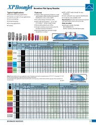
Flat Spray Tips<br />
Typical Applications:<br />
See selection guide on page 2 for<br />
recommended typical applications<br />
for Turbo TeeJet Induction tips.<br />
Features:<br />
n 110° wide angle, air induction, tapered flat<br />
spray tip pattern based on the patented<br />
outlet orifice design of the original Turbo<br />
TeeJet® nozzle.<br />
n Patented orifice design provides large,<br />
round passages to minimize plugging.<br />
n Depending on the chemical, produces<br />
large air-filled drops through a Venturi<br />
air aspirator resulting in less drift.<br />
n All polymer construction for excellent<br />
chemical and wear resistance.<br />
n Compact size to prevent tip damage.<br />
n Removable pre-orifice.<br />
n Ideal for use with automatic sprayer<br />
controllers.<br />
Removable<br />
Insert<br />
Pre-Orifice<br />
Mixing<br />
Chamber<br />
Two internal<br />
air inlets<br />
One external<br />
air inlet<br />
Exit Orifice with<br />
15° offset from<br />
vertical position<br />
TTI110___-VP Spray Tip<br />
(Cross Section View)<br />
Note: Due to pre-orifice design, this tip is not compatible<br />
with the 4193A check valve tip strainer.<br />
n Wide operating pressure range:<br />
15–100 PSI (1–7 bar).<br />
n Automatic alignment when used with<br />
25598-*-NYR Quick TeeJet® cap and gasket.<br />
See page 57 for additional information.<br />
TTI110015<br />
(100)<br />
TTI11002<br />
(50)<br />
TTI110025<br />
(50)<br />
TTI11003<br />
(50)<br />
TTI11004<br />
(50)<br />
TTI11005<br />
(50)<br />
TTI11006<br />
(50)<br />
psi<br />
Drop<br />
Size<br />
capacity<br />
one<br />
nozzle<br />
in GPM<br />
capacity<br />
one<br />
nozzle<br />
in<br />
oz./min.<br />
gpa<br />
209<br />
gallons per 1000 sq. ft.<br />
4 mph 5 mph 6 mph 8 mph 10 mph 12 mph 15 mph 20 mph 2 mph 3 mph 4 mph 5 mph<br />
15 UC 0.092 12 6.8 5.5 4.6 3.4 2.7 2.3 1.8 1.4 0.31 0.21 0.16 0.13<br />
20 UC 0.11 14 8.2 6.5 5.4 4.1 3.3 2.7 2.2 1.6 0.37 0.25 0.19 0.15<br />
30 UC 0.13 17 9.7 7.7 6.4 4.8 3.9 3.2 2.6 1.9 0.44 0.29 0.22 0.18<br />
40 UC 0.15 19 11.1 8.9 7.4 5.6 4.5 3.7 3.0 2.2 0.<strong>51</strong> 0.34 0.26 0.20<br />
50 UC 0.17 22 12.6 10.1 8.4 6.3 5.0 4.2 3.4 2.5 0.58 0.39 0.29 0.23<br />
60 XC 0.18 23 13.4 10.7 8.9 6.7 5.3 4.5 3.6 2.7 0.61 0.41 0.31 0.24<br />
70 XC 0.20 26 14.9 11.9 9.9 7.4 5.9 5.0 4.0 3.0 0.68 0.45 0.34 0.27<br />
80 XC 0.21 27 15.6 12.5 10.4 7.8 6.2 5.2 4.2 3.1 0.71 0.48 0.36 0.29<br />
90 XC 0.23 29 17.1 13.7 11.4 8.5 6.8 5.7 4.6 3.4 0.78 0.52 0.39 0.31<br />
100 XC 0.24 31 17.8 14.3 11.9 8.9 7.1 5.9 4.8 3.6 0.82 0.54 0.41 0.33<br />
15 UC 0.12 15 8.9 7.1 5.9 4.5 3.6 3.0 2.4 1.8 0.41 0.27 0.20 0.16<br />
20 UC 0.14 18 10.4 8.3 6.9 5.2 4.2 3.5 2.8 2.1 0.48 0.32 0.24 0.19<br />
30 UC 0.17 22 12.6 10.1 8.4 6.3 5.0 4.2 3.4 2.5 0.58 0.39 0.29 0.23<br />
40 UC 0.20 26 14.9 11.9 9.9 7.4 5.9 5.0 4.0 3.0 0.68 0.45 0.34 0.27<br />
50 UC 0.22 28 16.3 13.1 10.9 8.2 6.5 5.4 4.4 3.3 0.75 0.50 0.37 0.30<br />
60 UC 0.24 31 17.8 14.3 11.9 8.9 7.1 5.9 4.8 3.6 0.82 0.54 0.41 0.33<br />
70 XC 0.26 33 19.3 15.4 12.9 9.7 7.7 6.4 5.1 3.9 0.88 0.59 0.44 0.35<br />
80 XC 0.28 36 21 16.6 13.9 10.4 8.3 6.9 5.5 4.2 0.95 0.63 0.48 0.38<br />
90 XC 0.30 38 22 17.8 14.9 11.1 8.9 7.4 5.9 4.5 1.0 0.68 0.<strong>51</strong> 0.41<br />
100 XC 0.32 41 24 19.0 15.8 11.9 9.5 7.9 6.3 4.8 1.1 0.73 0.54 0.44<br />
15 UC 0.15 19 11.1 8.9 7.4 5.6 4.5 3.7 3.0 2.2 0.<strong>51</strong> 0.34 0.26 0.20<br />
20 UC 0.18 23 13.4 10.7 8.9 6.7 5.3 4.5 3.6 2.7 0.61 0.41 0.31 0.24<br />
30 UC 0.22 28 16.3 13.1 10.9 8.2 6.5 5.4 4.4 3.3 0.75 0.50 0.37 0.30<br />
40 UC 0.25 32 18.6 14.9 12.4 9.3 7.4 6.2 5.0 3.7 0.85 0.57 0.43 0.34<br />
50 UC 0.28 36 21 16.6 13.9 10.4 8.3 6.9 5.5 4.2 0.95 0.63 0.48 0.38<br />
60 UC 0.31 40 23 18.4 15.3 11.5 9.2 7.7 6.1 4.6 1.1 0.70 0.53 0.42<br />
70 XC 0.33 42 25 19.6 16.3 12.3 9.8 8.2 6.5 4.9 1.1 0.75 0.56 0.45<br />
80 XC 0.35 45 26 21 17.3 13.0 10.4 8.7 6.9 5.2 1.2 0.79 0.60 0.48<br />
90 XC 0.38 49 28 23 18.8 14.1 11.3 9.4 7.5 5.6 1.3 0.86 0.65 0.52<br />
100 XC 0.40 <strong>51</strong> 30 24 19.8 14.9 11.9 9.9 7.9 5.9 1.4 0.91 0.68 0.54<br />
15 UC 0.18 23 13.4 10.7 8.9 6.7 5.3 4.5 3.6 2.7 0.61 0.41 0.31 0.24<br />
20 UC 0.21 27 15.6 12.5 10.4 7.8 6.2 5.2 4.2 3.1 0.71 0.48 0.36 0.29<br />
30 UC 0.26 33 19.3 15.4 12.9 9.7 7.7 6.4 5.1 3.9 0.88 0.59 0.44 0.35<br />
40 UC 0.30 38 22 17.8 14.9 11.1 8.9 7.4 5.9 4.5 1.0 0.68 0.<strong>51</strong> 0.41<br />
50 UC 0.34 44 25 20 16.8 12.6 10.1 8.4 6.7 5.0 1.2 0.77 0.58 0.46<br />
60 UC 0.37 47 27 22 18.3 13.7 11.0 9.2 7.3 5.5 1.3 0.84 0.63 0.50<br />
70 XC 0.40 <strong>51</strong> 30 24 19.8 14.9 11.9 9.9 7.9 5.9 1.4 0.91 0.68 0.54<br />
80 XC 0.42 54 31 25 21 15.6 12.5 10.4 8.3 6.2 1.4 0.95 0.71 0.57<br />
90 XC 0.45 58 33 27 22 16.7 13.4 11.1 8.9 6.7 1.5 1.0 0.77 0.61<br />
100 XC 0.47 60 35 28 23 17.4 14.0 11.6 9.3 7.0 1.6 1.1 0.80 0.64<br />
15 UC 0.24 31 17.8 14.3 11.9 8.9 7.1 5.9 4.8 3.6 0.82 0.54 0.41 0.33<br />
20 UC 0.28 36 21 16.6 13.9 10.4 8.3 6.9 5.5 4.2 0.95 0.63 0.48 0.38<br />
30 UC 0.35 45 26 21 17.3 13.0 10.4 8.7 6.9 5.2 1.2 0.79 0.60 0.48<br />
40 UC 0.40 <strong>51</strong> 30 24 19.8 14.9 11.9 9.9 7.9 5.9 1.4 0.91 0.68 0.54<br />
50 UC 0.45 58 33 27 22 16.7 13.4 11.1 8.9 6.7 1.5 1.0 0.77 0.61<br />
60 UC 0.49 63 36 29 24 18.2 14.6 12.1 9.7 7.3 1.7 1.1 0.83 0.67<br />
70 XC 0.53 68 39 31 26 19.7 15.7 13.1 10.5 7.9 1.8 1.2 0.90 0.72<br />
80 XC 0.57 73 42 34 28 21 16.9 14.1 11.3 8.5 1.9 1.3 0.97 0.78<br />
90 XC 0.60 77 45 36 30 22 17.8 14.9 11.9 8.9 2.0 1.4 1.0 0.82<br />
100 XC 0.63 81 47 37 31 23 18.7 15.6 12.5 9.4 2.1 1.4 1.1 0.86<br />
15 UC 0.31 40 23 18.4 15.3 11.5 9.2 7.7 6.1 4.6 1.1 0.70 0.53 0.42<br />
20 UC 0.35 45 26 21 17.3 13.0 10.4 8.7 6.9 5.2 1.2 0.79 0.60 0.48<br />
30 UC 0.43 55 32 26 21 16.0 12.8 10.6 8.5 6.4 1.5 0.97 0.73 0.58<br />
40 UC 0.50 64 37 30 25 18.6 14.9 12.4 9.9 7.4 1.7 1.1 0.85 0.68<br />
50 UC 0.56 72 42 33 28 21 16.6 13.9 11.1 8.3 1.9 1.3 0.95 0.76<br />
60 UC 0.61 78 45 36 30 23 18.1 15.1 12.1 9.1 2.1 1.4 1.0 0.83<br />
70 XC 0.66 84 49 39 33 25 19.6 16.3 13.1 9.8 2.2 1.5 1.1 0.90<br />
80 XC 0.71 91 53 42 35 26 21 17.6 14.1 10.5 2.4 1.6 1.2 0.97<br />
90 XC 0.75 96 56 45 37 28 22 18.6 14.9 11.1 2.6 1.7 1.3 1.0<br />
100 XC 0.79 101 59 47 39 29 23 19.6 15.6 11.7 2.7 1.8 1.3 1.1<br />
15 UC 0.37 47 27 22 18.3 13.7 11.0 9.2 7.3 5.5 1.3 0.84 0.63 0.50<br />
20 UC 0.42 54 31 25 21 15.6 12.5 10.4 8.3 6.2 1.4 0.95 0.71 0.57<br />
30 UC 0.52 67 39 31 26 19.3 15.4 12.9 10.3 7.7 1.8 1.2 0.88 0.71<br />
40 UC 0.60 77 45 36 30 22 17.8 14.9 11.9 8.9 2.0 1.4 1.0 0.82<br />
50 UC 0.67 86 50 40 33 25 19.9 16.6 13.3 9.9 2.3 1.5 1.1 0.91<br />
60 UC 0.73 93 54 43 36 27 22 18.1 14.5 10.8 2.5 1.7 1.2 0.99<br />
70 XC 0.79 101 59 47 39 29 23 19.6 15.6 11.7 2.7 1.8 1.3 1.1<br />
80 XC 0.85 109 63 50 42 32 25 21 16.8 12.6 2.9 1.9 1.4 1.2<br />
90 XC 0.90 115 67 53 45 33 27 22 17.8 13.4 3.1 2.0 1.5 1.2<br />
100 XC 0.95 122 71 56 47 35 28 24 18.8 14.1 3.2 2.2 1.6 1.3<br />
Note: Always double check your application rates. Tabulations are based on spraying water at 70°F (21°C).<br />
See pages 124–140 for drop size classification, useful formulas and other information.<br />
CONTACT<br />
Product<br />
Spacing<br />
110°<br />
SYSTEMIC<br />
Product<br />
Optimum Spray Height<br />
DRIFT<br />
Management<br />
— EXCELLENT EXCELLENT<br />
209<br />
209<br />
Spray<br />
Height<br />
How to order:<br />
Specify tip number.<br />
Example:<br />
TTI11004-VP – Polymer with VisiFlo®<br />
color-coding<br />
BROADCAST NOZZLES<br />
9<br />
9
Extended Range Flat Spray Tips<br />
Typical Applications:<br />
See selection guide on page 2 for<br />
recommended typical applications<br />
for XR TeeJet tips.<br />
Features:<br />
n Excellent spray distribution over a wide<br />
range of pressures—15–60 PSI (1–4 bar).<br />
n Ideal for rigs equipped with sprayer<br />
controllers.<br />
n Reduces drift at lower pressures, better<br />
coverage at higher pressures.<br />
n Available in stainless steel, ceramic and<br />
polymer in 80° and 110° spray angles with<br />
VisiFlo® color-coding.<br />
n Ceramic is available with corrosiveresistant<br />
polypropylene VisiFlo colorcoded<br />
tip holder in 80° capacities 03–08<br />
and 110° capacities 02–08.<br />
n XR110025 only available in VK.<br />
n Brass available in 110° only.<br />
n Automatic spray alignment with<br />
25612-*-NYR Quick TeeJet® cap and gasket.<br />
Reference page 57 for more information.<br />
n Automatic spray alignment for sizes 10<br />
and 15 with 25610-*-NYR Quick TeeJet<br />
cap and gasket. Reference page 57 for<br />
more information.<br />
At 15 PSI (1 bar)<br />
Pressure<br />
At 60 PSI (4 bar)<br />
Pressure<br />
XR8001<br />
XR11001<br />
(100)<br />
XR80015<br />
XR110015<br />
(100)<br />
XR8002<br />
XR11002<br />
(50)<br />
XR110025<br />
(50)<br />
XR8003<br />
XR11003<br />
(50)<br />
XR8004<br />
XR11004<br />
(50)<br />
XR8005<br />
XR11005<br />
(50)<br />
XR8006<br />
XR11006<br />
(50)<br />
XR8008<br />
XR11008<br />
(50)<br />
XR8010†<br />
XR11010†<br />
XR8015†<br />
XR11015†<br />
capacity<br />
Drop capacity<br />
209<br />
one<br />
Size one<br />
nozzle<br />
nozzle<br />
psi<br />
in<br />
gpa<br />
gallons per 1000 sq. ft.<br />
in GPM<br />
80º 110º oz./min. 4 mph 5 mph 6 mph 8 mph 10 mph 12 mph 15 mph 20 mph 2 mph 3 mph 4 mph 5 mph<br />
15<br />
20<br />
M<br />
F<br />
F<br />
F<br />
0.061<br />
0.071<br />
7.8<br />
9.1<br />
4.5<br />
5.3<br />
3.6<br />
4.2<br />
3.0<br />
3.5<br />
2.3<br />
2.6<br />
1.8<br />
2.1<br />
1.5<br />
1.8<br />
1.2<br />
1.4<br />
0.91<br />
1.1<br />
0.21<br />
0.24<br />
0.14<br />
0.16<br />
0.10<br />
0.12<br />
0.08<br />
0.10<br />
30 F F 0.087 11 6.5 5.2 4.3 3.2 2.6 2.2 1.7 1.3 0.30 0.20 0.15 0.12<br />
40 F F 0.10 13 7.4 5.9 5.0 3.7 3.0 2.5 2.0 1.5 0.34 0.23 0.17 0.14<br />
50 F VF 0.11 14 8.2 6.5 5.4 4.1 3.3 2.7 2.2 1.6 0.37 0.25 0.19 0.15<br />
60 F VF 0.12 15 8.9 7.1 5.9 4.5 3.6 3.0 2.4 1.8 0.41 0.27 0.20 0.16<br />
15 M F 0.092 12 6.8 5.5 4.6 3.4 2.7 2.3 1.8 1.4 0.31 0.21 0.16 0.13<br />
20 M F 0.11 14 8.2 6.5 5.4 4.1 3.3 2.7 2.2 1.6 0.37 0.25 0.19 0.15<br />
30 F F 0.13 17 9.7 7.7 6.4 4.8 3.9 3.2 2.6 1.9 0.44 0.29 0.22 0.18<br />
40 F F 0.15 19 11.1 8.9 7.4 5.6 4.5 3.7 3.0 2.2 0.<strong>51</strong> 0.34 0.26 0.20<br />
50 F F 0.17 22 12.6 10.1 8.4 6.3 5.0 4.2 3.4 2.5 0.58 0.39 0.29 0.23<br />
60 F F 0.18 23 13.4 10.7 8.9 6.7 5.3 4.5 3.6 2.7 0.61 0.41 0.31 0.24<br />
15 M M 0.12 15 8.9 7.1 5.9 4.5 3.6 3.0 2.4 1.8 0.41 0.27 0.20 0.16<br />
20 M F 0.14 18 10.4 8.3 6.9 5.2 4.2 3.5 2.8 2.1 0.48 0.32 0.24 0.19<br />
30 M F 0.17 22 12.6 10.1 8.4 6.3 5.0 4.2 3.4 2.5 0.58 0.39 0.29 0.23<br />
40 F F 0.20 26 14.9 11.9 9.9 7.4 5.9 5.0 4.0 3.0 0.68 0.45 0.34 0.27<br />
50 F F 0.22 28 16.3 13.1 10.9 8.2 6.5 5.4 4.4 3.3 0.75 0.50 0.37 0.30<br />
60 F F 0.24 31 17.8 14.3 11.9 8.9 7.1 5.9 4.8 3.6 0.82 0.54 0.41 0.33<br />
15 M 0.15 19 11.1 8.9 7.4 5.6 4.5 3.7 3.0 2.2 0.<strong>51</strong> 0.34 0.26 0.20<br />
20 M 0.18 23 13.4 10.7 8.9 6.7 5.3 4.5 3.6 2.7 0.61 0.41 0.31 0.24<br />
30 F 0.22 28 16.3 13.1 10.9 8.2 6.5 5.4 4.4 3.3 0.75 0.50 0.37 0.30<br />
40 F 0.25 32 18.6 14.9 12.4 9.3 7.4 6.2 5.0 3.7 0.85 0.57 0.43 0.34<br />
50 F 0.28 36 21 16.6 13.9 10.4 8.3 6.9 5.5 4.2 0.95 0.63 0.48 0.38<br />
60 F 0.31 40 23 18.4 15.3 11.5 9.2 7.7 6.1 4.6 1.1 0.70 0.53 0.42<br />
15 M M 0.18 23 13.4 10.7 8.9 6.7 5.3 4.5 3.6 2.7 0.61 0.41 0.31 0.24<br />
20 M M 0.21 27 15.6 12.5 10.4 7.8 6.2 5.2 4.2 3.1 0.71 0.48 0.36 0.29<br />
30 M F 0.26 33 19.3 15.4 12.9 9.7 7.7 6.4 5.1 3.9 0.88 0.59 0.44 0.35<br />
40 M F 0.30 38 22 17.8 14.9 11.1 8.9 7.4 5.9 4.5 1.0 0.68 0.<strong>51</strong> 0.41<br />
50 M F 0.34 44 25 20 16.8 12.6 10.1 8.4 6.7 5.0 1.2 0.77 0.58 0.46<br />
60 F F 0.37 47 27 22 18.3 13.7 11.0 9.2 7.3 5.5 1.3 0.84 0.63 0.50<br />
15 C M 0.24 31 17.8 14.3 11.9 8.9 7.1 5.9 4.8 3.6 0.82 0.54 0.41 0.33<br />
20 C M 0.28 36 21 16.6 13.9 10.4 8.3 6.9 5.5 4.2 1.0 0.63 0.48 0.38<br />
30 M M 0.35 45 26 21 17.3 13.0 10.4 8.7 6.9 5.2 1.2 0.79 0.60 0.48<br />
40 M M 0.40 <strong>51</strong> 30 24 19.8 14.9 11.9 9.9 7.9 5.9 1.4 0.91 0.68 0.54<br />
50 M F 0.45 58 33 27 22 16.7 13.4 11.1 8.9 6.7 1.5 1.0 0.77 0.61<br />
60 M F 0.49 63 36 29 24 18.2 14.6 12.1 9.7 7.3 1.7 1.1 0.83 0.67<br />
15 C M 0.31 40 23 18.4 15.3 11.5 9.2 7.7 6.1 4.6 1.1 0.70 0.53 0.42<br />
20 C M 0.35 45 26 21 17.3 13.0 10.4 8.7 6.9 5.2 1.2 0.79 0.60 0.48<br />
30 C M 0.43 55 32 26 21 16.0 12.8 10.6 8.5 6.4 1.5 0.97 0.73 0.58<br />
40 M M 0.50 64 37 30 25 18.6 14.9 12.4 9.9 7.4 1.7 1.1 0.85 0.68<br />
50 M M 0.56 72 42 33 28 21 16.6 13.9 11.1 8.3 1.9 1.3 0.95 0.76<br />
60 M F 0.61 78 45 36 30 23 18.1 15.1 12.1 9.1 2.1 1.4 1.0 0.83<br />
15 C C 0.37 47 27 22 18.3 13.7 11.0 9.2 7.3 5.5 1.3 0.84 0.63 0.50<br />
20 C C 0.42 54 31 25 21 15.6 12.5 10.4 8.3 6.2 1.4 1.0 0.71 0.57<br />
30 C M 0.52 67 39 31 26 19.3 15.4 12.9 10.3 7.7 1.8 1.2 0.88 0.71<br />
40 C M 0.60 77 45 36 30 22 17.8 14.9 11.9 8.9 2.0 1.4 1.0 0.82<br />
50 C M 0.67 86 50 40 33 25 19.9 16.6 13.3 9.9 2.3 1.5 1.1 0.91<br />
60 C M 0.73 93 54 43 36 27 22 18.1 14.5 10.8 2.5 1.7 1.2 0.99<br />
15 VC C 0.49 63 36 29 24 18.2 14.6 12.1 9.7 7.3 1.7 1.1 0.83 0.67<br />
20 VC C 0.57 73 42 34 28 21 16.9 14.1 11.3 8.5 1.9 1.3 0.97 0.78<br />
30 C C 0.69 88 <strong>51</strong> 41 34 26 20 17.1 13.7 10.2 2.3 1.6 1.2 0.94<br />
40 C C 0.80 102 59 48 40 30 24 19.8 15.8 11.9 2.7 1.8 1.4 1.1<br />
50 C M 0.89 114 66 53 44 33 26 22 17.6 13.2 3.0 2.0 1.5 1.2<br />
60 C M 0.98 125 73 58 49 36 29 24 19.4 14.6 3.3 2.2 1.7 1.3<br />
15 VC 0.61 78 45 36 30 23 18.1 15.1 12.1 9.1 2.1 1.4 1.0 0.83<br />
20 VC 0.71 91 53 42 35 26 21 17.6 14.1 10.5 2.4 1.6 1.2 0.97<br />
30 C 0.87 111 65 52 43 32 26 22 17.2 12.9 3.0 2.0 1.5 1.2<br />
40 C 1.00 128 74 59 50 37 30 25 19.8 14.9 3.4 2.3 1.7 1.4<br />
50 C 1.12 143 83 67 55 42 33 28 22 16.6 3.8 2.5 1.9 1.5<br />
60 M 1.22 156 91 72 60 45 36 30 24 18.1 4.1 2.8 2.1 1.7<br />
15 XC 0.92 118 68 55 46 34 27 23 18.2 13.7 3.1 2.1 1.6 1.3<br />
20 XC 1.06 136 79 63 52 39 31 26 21 15.7 3.6 2.4 1.8 1.4<br />
30 VC 1.30 166 97 77 64 48 39 32 26 19.3 4.4 2.9 2.2 1.8<br />
40 C 1.50 192 111 89 74 56 45 37 30 22 5.1 3.4 2.6 2.0<br />
50 C 1.68 215 125 100 83 62 50 42 33 25 5.7 3.8 2.9 2.3<br />
60 C 1.84 236 137 109 91 68 55 46 36 27 6.3 4.2 3.1 2.5<br />
Note: Always double check your application rates. Tabulations are based on spraying water at 70°F (21°C).<br />
See pages 124–140 for drop size classification, useful formulas and other information.<br />
†Available in all stainless steel only.<br />
CONTACT<br />
Product<br />
Spacing<br />
Optimum Spray Height<br />
80°<br />
110°<br />
SYSTEMIC<br />
Product<br />
DRIFT<br />
Management<br />
EXCELLENT Good Good<br />
Good* VERY GOOD* VERY GOOD*<br />
*At pressures below 30 PSI (2.0 bar)<br />
209<br />
309<br />
209<br />
Spray<br />
Height<br />
How to order:<br />
Specify tip number.<br />
Examples:<br />
XR8004VS – Stainless Steel with<br />
VisiFlo color-coding<br />
XR11004-VP – Polymer with VisiFlo<br />
color-coding (110º only)<br />
XR11004-VK – Ceramic with<br />
polypropylene<br />
VisiFlo colorcoding<br />
XR8010SS – Stainless Steel<br />
XR11004VB – Brass with VisiFlo<br />
color-coding<br />
(110° only)<br />
10<br />
BROADCAST NOZZLES
Extended Range Flat Spray Tips<br />
Typical Applications:<br />
See selection guide on page 2 for<br />
recommended typical applications for<br />
XRC TeeJet tips.<br />
Features:<br />
n Excellent spray distribution over a wide range<br />
of pressures—15–60 PSI (1–4 bar).<br />
n Ideal for rigs equipped with sprayer controllers.<br />
n Reduces drift at lower pressures, better<br />
coverage at higher pressures.<br />
n 80° available in stainless steel (015, 02, 03–06<br />
capacities) and ceramic (02, 03–08 capacities).<br />
n 110° available in stainless steel (025–05<br />
capacities), ceramic (02–08 capacities) and<br />
polymer (025–20 capacities).<br />
n XR TeeJet tip molded into Quick TeeJet® cap<br />
provides automatic spray alignment.<br />
n <strong>Inc</strong>ludes tightly fitting washer that stays put<br />
and assures a good seal.<br />
At 15 PSI (1 bar)<br />
Pressure<br />
At 60 PSI (4 bar)<br />
Pressure<br />
XRC80015<br />
(100)<br />
XRC8002<br />
XRC11002<br />
(50)<br />
XRC110025<br />
(50)<br />
XRC8003<br />
XRC11003<br />
(50)<br />
XRC8004<br />
XRC11004<br />
(50)<br />
XRC8005<br />
XRC11005<br />
(50)<br />
XRC8006<br />
XRC11006<br />
(50)<br />
XRC8008<br />
XRC11008<br />
(50)<br />
XRC11010<br />
XRC11015<br />
XRC11020<br />
capacity<br />
Drop capacity<br />
209<br />
one<br />
Size one<br />
nozzle<br />
nozzle<br />
psi<br />
in<br />
gpa<br />
gallons per 1000 sq. ft.<br />
in GPM<br />
80º 110º oz./min. 4 mph 5 mph 6 mph 8 mph 10 mph 12 mph 15 mph 20 mph 2 mph 3 mph 4 mph 5 mph<br />
15 M 0.092 12 6.8 5.5 4.6 3.4 2.7 2.3 1.8 1.4 0.31 0.21 0.16 0.13<br />
20 M 0.11 14 8.2 6.5 5.4 4.1 3.3 2.7 2.2 1.6 0.37 0.25 0.19 0.15<br />
30 F 0.13 17 9.7 7.7 6.4 4.8 3.9 3.2 2.6 1.9 0.44 0.29 0.22 0.18<br />
40 F 0.15 19 11.1 8.9 7.4 5.6 4.5 3.7 3.0 2.2 0.<strong>51</strong> 0.34 0.26 0.20<br />
50 F 0.17 22 12.6 10.1 8.4 6.3 5.0 4.2 3.4 2.5 0.58 0.39 0.29 0.23<br />
60 F 0.18 23 13.4 10.7 8.9 6.7 5.3 4.5 3.6 2.7 0.61 0.41 0.31 0.24<br />
15 M M 0.12 15 8.9 7.1 5.9 4.5 3.6 3.0 2.4 1.8 0.41 0.27 0.20 0.16<br />
20 M F 0.14 18 10.4 8.3 6.9 5.2 4.2 3.5 2.8 2.1 0.48 0.32 0.24 0.19<br />
30 M F 0.17 22 12.6 10.1 8.4 6.3 5.0 4.2 3.4 2.5 0.58 0.39 0.29 0.23<br />
40 F F 0.20 26 14.9 11.9 9.9 7.4 5.9 5.0 4.0 3.0 0.68 0.45 0.34 0.27<br />
50 F F 0.22 28 16.3 13.1 10.9 8.2 6.5 5.4 4.4 3.3 0.75 0.50 0.37 0.30<br />
60 F F 0.24 31 17.8 14.3 11.9 8.9 7.1 5.9 4.8 3.6 0.82 0.54 0.41 0.33<br />
15 M 0.15 19 11.1 8.9 7.4 5.6 4.5 3.7 3.0 2.2 0.<strong>51</strong> 0.34 0.26 0.20<br />
20 M 0.18 23 13.4 10.7 8.9 6.7 5.3 4.5 3.6 2.7 0.61 0.41 0.31 0.24<br />
30 F 0.22 28 16.3 13.1 10.9 8.2 6.5 5.4 4.4 3.3 0.75 0.50 0.37 0.30<br />
40 F 0.25 32 18.6 14.9 12.4 9.3 7.4 6.2 5.0 3.7 0.85 0.57 0.43 0.34<br />
50 F 0.28 36 21 16.6 13.9 10.4 8.3 6.9 5.5 4.2 0.95 0.63 0.48 0.38<br />
60 F 0.31 40 23 18.4 15.3 11.5 9.2 7.7 6.1 4.6 1.1 0.70 0.53 0.42<br />
15 M M 0.18 23 13.4 10.7 8.9 6.7 5.3 4.5 3.6 2.7 0.61 0.41 0.31 0.24<br />
20 M M 0.21 27 15.6 12.5 10.4 7.8 6.2 5.2 4.2 3.1 0.71 0.48 0.36 0.29<br />
30 M F 0.26 33 19.3 15.4 12.9 9.7 7.7 6.4 5.1 3.9 0.88 0.59 0.44 0.35<br />
40 M F 0.30 38 22 17.8 14.9 11.1 8.9 7.4 5.9 4.5 1.0 0.68 0.<strong>51</strong> 0.41<br />
50 M F 0.34 44 25 20 16.8 12.6 10.1 8.4 6.7 5.0 1.2 0.77 0.58 0.46<br />
60 F F 0.37 47 27 22 18.3 13.7 11.0 9.2 7.3 5.5 1.3 0.84 0.63 0.50<br />
15 C M 0.24 31 17.8 14.3 11.9 8.9 7.1 5.9 4.8 3.6 0.82 0.54 0.41 0.33<br />
20 C M 0.28 36 21 16.6 13.9 10.4 8.3 6.9 5.5 4.2 0.95 0.63 0.48 0.38<br />
30 M M 0.35 45 26 21 17.3 13.0 10.4 8.7 6.9 5.2 1.2 0.79 0.60 0.48<br />
40 M M 0.40 <strong>51</strong> 30 24 19.8 14.9 11.9 9.9 7.9 5.9 1.4 0.91 0.68 0.54<br />
50 M F 0.45 58 33 27 22 16.7 13.4 11.1 8.9 6.7 1.5 1.0 0.77 0.61<br />
60 M F 0.49 63 36 29 24 18.2 14.6 12.1 9.7 7.3 1.7 1.1 0.83 0.67<br />
15 C M 0.31 40 23 18.4 15.3 11.5 9.2 7.7 6.1 4.6 1.1 0.70 0.53 0.42<br />
20 C M 0.35 45 26 21 17.3 13.0 10.4 8.7 6.9 5.2 1.2 0.79 0.60 0.48<br />
30 C M 0.43 55 32 26 21 16.0 12.8 10.6 8.5 6.4 1.5 0.97 0.73 0.58<br />
40 M M 0.50 64 37 30 25 18.6 14.9 12.4 9.9 7.4 1.7 1.1 0.85 0.68<br />
50 M M 0.56 72 42 33 28 21 16.6 13.9 11.1 8.3 1.9 1.3 0.95 0.76<br />
60 M F 0.61 78 45 36 30 23 18.1 15.1 12.1 9.1 2.1 1.4 1.0 0.83<br />
15 C C 0.37 47 27 22 18.3 13.7 11.0 9.2 7.3 5.5 1.3 0.84 0.63 0.50<br />
20 C C 0.42 54 31 25 21 15.6 12.5 10.4 8.3 6.2 1.4 0.95 0.71 0.57<br />
30 C M 0.52 67 39 31 26 19.3 15.4 12.9 10.3 7.7 1.8 1.2 0.88 0.71<br />
40 C M 0.60 77 45 36 30 22 17.8 14.9 11.9 8.9 2.0 1.4 1.0 0.82<br />
50 C M 0.67 86 50 40 33 25 19.9 16.6 13.3 9.9 2.3 1.5 1.1 0.91<br />
60 C M 0.73 93 54 43 36 27 22 18.1 14.5 10.8 2.5 1.7 1.2 0.99<br />
15 VC C 0.49 63 36 29 24 18.2 14.6 12.1 9.7 7.3 1.7 1.1 0.83 0.67<br />
20 VC C 0.57 73 42 34 28 21 16.9 14.1 11.3 8.5 1.9 1.3 0.97 0.78<br />
30 C C 0.69 88 <strong>51</strong> 41 34 26 20 17.1 13.7 10.2 2.3 1.6 1.2 0.94<br />
40 C C 0.80 102 59 48 40 30 24 19.8 15.8 11.9 2.7 1.8 1.4 1.1<br />
50 C M 0.89 114 66 53 44 33 26 22 17.6 13.2 3.0 2.0 1.5 1.2<br />
60 C M 0.98 125 73 58 49 36 29 24 19.4 14.6 3.3 2.2 1.7 1.3<br />
15 VC 0.61 78 45 36 30 23 18.1 15.1 12.1 9.1 2.1 1.4 1.0 0.83<br />
20 VC 0.71 91 53 42 35 26 21 17.6 14.1 10.5 2.4 1.6 1.2 0.97<br />
30 C 0.87 111 65 52 43 32 26 22 17.2 12.9 3.0 2.0 1.5 1.2<br />
40 C 1.00 128 74 59 50 37 30 25 19.8 14.9 3.4 2.3 1.7 1.4<br />
50 C 1.12 143 83 67 55 42 33 28 22 16.6 3.8 2.5 1.9 1.5<br />
60 M 1.22 156 91 72 60 45 36 30 24 18.1 4.1 2.8 2.1 1.7<br />
15 XC 0.92 118 68 55 46 34 27 23 18.2 13.7 3.1 2.1 1.6 1.3<br />
20 XC 1.06 136 79 63 52 39 31 26 21 15.7 3.6 2.4 1.8 1.4<br />
30 VC 1.30 166 97 77 64 48 39 32 26 19.3 4.4 2.9 2.2 1.8<br />
40 C 1.50 192 111 89 74 56 45 37 30 22 5.1 3.4 2.6 2.0<br />
50 C 1.68 215 125 100 83 62 50 42 33 25 5.7 3.8 2.9 2.3<br />
60 C 1.84 236 137 109 91 68 55 46 36 27 6.3 4.2 3.1 2.5<br />
15 XC 1.22 156 91 72 60 45 36 30 24 18.1 4.1 2.8 2.1 1.7<br />
20 XC 1.41 180 105 84 70 52 42 35 28 21 4.8 3.2 2.4 1.9<br />
30 VC 1.73 221 128 103 86 64 <strong>51</strong> 43 34 26 5.9 3.9 2.9 2.4<br />
40 VC 2.00 256 149 119 99 74 59 50 40 30 6.8 4.5 3.4 2.7<br />
50 VC 2.24 287 166 133 111 83 67 55 44 33 7.6 5.1 3.8 3.0<br />
60 VC 2.45 314 182 146 121 91 73 61 49 36 8.3 5.6 4.2 3.3<br />
Note: Always double check your application rates. Tabulations are based on spraying water at 70°F (21°C).<br />
See pages 124–140 for drop size classification, useful formulas and other information.<br />
BROADCAST NOZZLES<br />
CONTACT<br />
Product<br />
Spacing<br />
80°<br />
110°<br />
SYSTEMIC<br />
Product<br />
Optimum Spray Height<br />
DRIFT<br />
Management<br />
EXCELLENT Good Good<br />
Good* VERY GOOD* VERY GOOD*<br />
*At pressures below 30 PSI (2.0 bar)<br />
209<br />
309<br />
209<br />
Spray<br />
Height<br />
How to order:<br />
Specify tip number.<br />
Examples:<br />
XRC11004-VS – Stainless Steel with<br />
VisiFlo® color-coding<br />
XRC11004-VP – Polymer with VisiFlo<br />
color-coding<br />
XRC11004-VK – Ceramic with VisiFlo<br />
color-coding<br />
11<br />
11
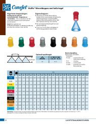
VisiFlo® Flat Spray Tips<br />
Features:<br />
n Tapered edge flat spray pattern for uniform<br />
coverage in broadcast spraying.<br />
n VisiFlo color-coded version available in<br />
stainless steel, ceramic and polymer in<br />
80° or 110° spray angles in selected sizes.<br />
n Available in ceramic 80° capacities 01–02<br />
and 110° capacities 01–015. See XR and<br />
XRC TeeJet® tips on page 10–11 for larger<br />
capacities.<br />
n Standard version (not color-coded)<br />
available in 15°, 25°, 40°, 50° and 65°<br />
spray angles in brass, stainless steel<br />
or hardened stainless steel.<br />
n See page 31 for TeeJet even flat spray tips.<br />
n Automatic spray alignment with 25612-*-NYR<br />
Quick TeeJet® cap and gasket. Reference<br />
page 57 for more information.<br />
n Automatic spray alignment for sizes<br />
10 through 20 with 25610-*-NYR Quick<br />
TeeJet cap and gasket. Reference page 57<br />
for more information.<br />
capacity<br />
Drop capacity<br />
one<br />
209<br />
Size one<br />
nozzle<br />
nozzle<br />
psi<br />
in<br />
gpa<br />
gallons per 1000 sq. ft.<br />
in GPM<br />
80º 110º oz./min. 4 mph 5 mph 6 mph 8 mph 10 mph 12 mph 15 mph 20 mph 2 mph 3 mph 4 mph 5 mph<br />
TP650050† 30 0.043 5.5 3.2 2.6 2.1 1.6 1.3 1.1 0.85 0.64 0.15 0.10 0.07 0.06<br />
35 0.047 6.0 3.5 2.8 2.3 1.7 1.4 1.2 0.93 0.70 0.16 0.11 0.08 0.06<br />
TP800050†<br />
40 0.050 6.4 3.7 3.0 2.5 1.9 1.5 1.2 0.99 0.74 0.17 0.11 0.09 0.07<br />
TP1100050†<br />
50 0.056 7.2 4.2 3.3 2.8 2.1 1.7 1.4 1.1 0.83 0.19 0.13 0.10 0.08<br />
(100) 60 0.061 7.8 4.5 3.6 3.0 2.3 1.8 1.5 1.2 0.91 0.21 0.14 0.10 0.08<br />
TP650067† 30 0.058 7.4 4.3 3.4 2.9 2.2 1.7 1.4 1.1 0.86 0.20 0.13 0.10 0.08<br />
TP800067† 35 0.063 8.1 4.7 3.7 3.1 2.3 1.9 1.6 1.2 0.94 0.21 0.14 0.11 0.09<br />
40 0.067 8.6 5.0 4.0 3.3 2.5 2.0 1.7 1.3 0.99 0.23 0.15 0.11 0.09<br />
TP1100067†<br />
50 0.075 9.6 5.6 4.5 3.7 2.8 2.2 1.9 1.5 1.1 0.26 0.17 0.13 0.10<br />
(100) 60 0.082 10 6.1 4.9 4.1 3.0 2.4 2.0 1.6 1.2 0.28 0.19 0.14 0.11<br />
TP6501† 30 F F 0.087 11 6.5 5.2 4.3 3.2 2.6 2.2 1.7 1.3 0.30 0.20 0.15 0.12<br />
TP8001 35 F F 0.094 12 7.0 5.6 4.7 3.5 2.8 2.3 1.9 1.4 0.32 0.21 0.16 0.13<br />
40 F F 0.10 13 7.4 5.9 5.0 3.7 3.0 2.5 2.0 1.5 0.34 0.23 0.17 0.14<br />
TP11001<br />
50 F VF 0.11 14 8.2 6.5 5.4 4.1 3.3 2.7 2.2 1.6 0.37 0.25 0.19 0.15<br />
(100) 60 F VF 0.12 15 8.9 7.1 5.9 4.5 3.6 3.0 2.4 1.8 0.41 0.27 0.20 0.16<br />
TP65015† 30 F F 0.13 17 9.7 7.7 6.4 4.8 3.9 3.2 2.6 1.9 0.44 0.29 0.22 0.18<br />
TP80015 35 F F 0.14 18 10.4 8.3 6.9 5.2 4.2 3.5 2.8 2.1 0.48 0.32 0.24 0.19<br />
40 F F 0.15 19 11.1 8.9 7.4 5.6 4.5 3.7 3.0 2.2 0.<strong>51</strong> 0.34 0.26 0.20<br />
TP110015<br />
50 F F 0.17 22 12.6 10.1 8.4 6.3 5.0 4.2 3.4 2.5 0.58 0.39 0.29 0.23<br />
(100) 60 F F 0.18 23 13.4 10.7 8.9 6.7 5.3 4.5 3.6 2.7 0.61 0.41 0.31 0.24<br />
TP6502† 30 M F 0.17 22 12.6 10.1 8.4 6.3 5.0 4.2 3.4 2.5 0.58 0.39 0.29 0.23<br />
TP8002 35 M F 0.19 24 14.1 11.3 9.4 7.1 5.6 4.7 3.8 2.8 0.65 0.43 0.32 0.26<br />
40 F F 0.20 26 14.9 11.9 9.9 7.4 5.9 5.0 4.0 3.0 0.68 0.45 0.34 0.27<br />
TP11002<br />
50 F F 0.22 28 16.3 13.1 10.9 8.2 6.5 5.4 4.4 3.3 0.75 0.50 0.37 0.30<br />
(50) 60 F F 0.24 31 17.8 14.3 11.9 8.9 7.1 5.9 4.8 3.6 0.82 0.54 0.41 0.33<br />
TP6503† 30 M F 0.26 33 19.3 15.4 12.9 9.7 7.7 6.4 5.1 3.9 0.88 0.59 0.44 0.35<br />
TP8003 35 M F 0.28 36 21 16.6 13.9 10.4 8.3 6.9 5.5 4.2 0.95 0.63 0.48 0.38<br />
40 M F 0.30 38 22 17.8 14.9 11.1 8.9 7.4 5.9 4.5 1.0 0.68 0.<strong>51</strong> 0.41<br />
TP11003<br />
50 M F 0.34 44 25 20 16.8 12.6 10.1 8.4 6.7 5.0 1.2 0.77 0.58 0.46<br />
(50) 60 F F 0.37 47 27 22 18.3 13.7 11.0 9.2 7.3 5.5 1.3 0.84 0.63 0.50<br />
TP6504† 30 M M 0.35 45 26 21 17.3 13.0 10.4 8.7 6.9 5.2 1.2 0.79 0.60 0.48<br />
TP8004 35 M M 0.37 47 27 22 18.3 13.7 11.0 9.2 7.3 5.5 1.3 0.84 0.63 0.50<br />
40 M M 0.40 <strong>51</strong> 30 24 19.8 14.9 11.9 9.9 7.9 5.9 1.4 0.91 0.68 0.54<br />
TP11004<br />
50 M F 0.45 58 33 27 22 16.7 13.4 11.1 8.9 6.7 1.5 1.0 0.77 0.61<br />
(50) 60 M F 0.49 63 36 29 24 18.2 14.6 12.1 9.7 7.3 1.7 1.1 0.83 0.67<br />
TP6505† 30 C M 0.43 55 32 26 21 16.0 12.8 10.6 8.5 6.4 1.5 0.97 0.73 0.58<br />
TP8005 35 M M 0.47 60 35 28 23 17.4 14.0 11.6 9.3 7.0 1.6 1.1 0.80 0.64<br />
40 M M 0.50 64 37 30 25 18.6 14.9 12.4 9.9 7.4 1.7 1.1 0.85 0.68<br />
TP11005<br />
50 M M 0.56 72 42 33 28 21 16.6 13.9 11.1 8.3 1.9 1.3 0.95 0.76<br />
(50) 60 M F 0.61 78 45 36 30 23 18.1 15.1 12.1 9.1 2.1 1.4 1.0 0.83<br />
TP6506† 30 C M 0.52 67 39 31 26 19.3 15.4 12.9 10.3 7.7 1.8 1.2 0.88 0.71<br />
TP8006 35 C M 0.56 72 42 33 28 21 16.6 13.9 11.1 8.3 1.9 1.3 0.95 0.76<br />
40 C M 0.60 77 45 36 30 22 17.8 14.9 11.9 8.9 2.0 1.4 1.0 0.82<br />
TP11006<br />
50 C M 0.67 86 50 40 33 25 19.9 16.6 13.3 9.9 2.3 1.5 1.1 0.91<br />
(50) 60 C M 0.73 93 54 43 36 27 22 18.1 14.5 10.8 2.5 1.7 1.2 0.99<br />
TP6508† 30 C C 0.69 88 <strong>51</strong> 41 34 26 20 17.1 13.7 10.2 2.3 1.6 1.2 0.94<br />
TP8008 35 C C 0.75 96 56 45 37 28 22 18.6 14.9 11.1 2.6 1.7 1.3 1.0<br />
40 C C 0.80 102 59 48 40 30 24 19.8 15.8 11.9 2.7 1.8 1.4 1.1<br />
TP11008<br />
50 C M 0.89 114 66 53 44 33 26 22 17.6 13.2 3.0 2.0 1.5 1.2<br />
(50)<br />
TP6<strong>51</strong>0†<br />
TP8010†<br />
TP11010†<br />
TP6<strong>51</strong>5†<br />
TP8015†<br />
TP11015†<br />
TP6520†<br />
TP8020†<br />
TP11020†<br />
60 C M 0.98 125 73 58 49 36 29 24 19.4 14.6 3.3 2.2 1.7 1.3<br />
30 0.87 111 65 52 43 32 26 22 17.2 12.9 3.0 2.0 1.5 1.2<br />
35 0.94 120 70 56 47 35 28 23 18.6 14.0 3.2 2.1 1.6 1.3<br />
40 1.00 128 74 59 50 37 30 25 19.8 14.9 3.4 2.3 1.7 1.4<br />
50 1.12 143 83 67 55 42 33 28 22 16.6 3.8 2.5 1.9 1.5<br />
60 1.22 156 91 72 60 45 36 30 24 18.1 4.1 2.8 2.1 1.7<br />
30 1.30 166 97 77 64 48 39 32 26 19.3 4.4 2.9 2.2 1.8<br />
35 1.40 179 104 83 69 52 42 35 28 21 4.8 3.2 2.4 1.9<br />
40 1.50 192 111 89 74 56 45 37 30 22 5.1 3.4 2.6 2.0<br />
50 1.68 215 125 100 83 62 50 42 33 25 5.7 3.8 2.9 2.3<br />
60 1.84 236 137 109 91 68 55 46 36 27 6.3 4.2 3.1 2.5<br />
30 1.73 221 128 103 86 64 <strong>51</strong> 43 34 26 5.9 3.9 2.9 2.4<br />
35 1.87 239 139 111 93 69 56 46 37 28 6.4 4.2 3.2 2.5<br />
40 2.00 256 149 119 99 74 59 50 40 30 6.8 4.5 3.4 2.7<br />
50 2.24 287 166 133 111 83 67 55 44 33 7.6 5.1 3.8 3.0<br />
60 2.45 314 182 146 121 91 73 61 49 36 8.3 5.6 4.2 3.3<br />
Note: Always double check your application rates. Tabulations are based on spraying water at 70°F (21°C). See pages 124–140<br />
for drop size classification, useful formulas and other information.<br />
†Available in brass and/or stainless steel and/or hardened stainless steel.<br />
Spacing<br />
Optimum Spray Height<br />
65°<br />
80°<br />
110°<br />
209<br />
359<br />
309<br />
209<br />
Spray<br />
Height<br />
How to order:<br />
Specify tip number.<br />
Examples:<br />
TP8002VS – Stainless Steel with<br />
VisiFlo color-coding<br />
TP11002VP – Polymer with VisiFlo<br />
color-coding<br />
TP11002-HSS – Hardened<br />
Stainless Steel<br />
TP8002-SS – Stainless Steel<br />
TP8002 – Brass<br />
12<br />
BROADCAST NOZZLES
Drift Guard Flat Spray Tips<br />
Removable<br />
Pre-Orifice<br />
(Celcon®)<br />
Features:<br />
n Pre-orifice design produces larger droplets<br />
and reduces the small drift-prone droplets,<br />
minimizing off-target spray contamination.<br />
n Tapered edge flat spray pattern provides<br />
uniform coverage when adjacent nozzle<br />
patterns are overlapped in broadcast<br />
spraying.<br />
n The color-coded pre-orifice is removable<br />
for any necessary cleaning operations.<br />
n Available in both 80° and 110° spray angles<br />
with a durable stainless steel orifice.<br />
n Automatic spray alignment with 25612-*-NYR<br />
Quick TeeJet® cap and gasket. Reference<br />
page 57 for more information.<br />
Tip Insert Holder<br />
(Celcon)<br />
Tip Insert<br />
(Stainless Steel)<br />
Drift Guard<br />
(Cross Section View)<br />
Note: Due to the pre-orifice design, this tip is not<br />
compatible with the 4193A check valve tip strainer.<br />
Spacing<br />
DG80015†<br />
DG110015<br />
(100)<br />
DG8002†<br />
DG11002<br />
(50)<br />
DG8003†<br />
DG11003<br />
(50)<br />
DG8004†<br />
DG11004<br />
(50)<br />
DG8005†<br />
DG11005<br />
(50)<br />
capacity<br />
Drop capacity<br />
one<br />
209<br />
Size one<br />
nozzle<br />
nozzle<br />
psi<br />
in<br />
gpa<br />
gallons per 1000 sq. ft.<br />
in GPM<br />
80º 110º oz./min. 4 mph 5 mph 6 mph 8 mph 10 mph 12 mph 15 mph 20 mph 2 mph 3 mph 4 mph 5 mph<br />
30 M M 0.13 17 9.7 7.7 6.4 4.8 3.9 3.2 2.6 1.9 0.44 0.29 0.22 0.18<br />
35 M M 0.14 18 10.4 8.3 6.9 5.2 4.2 3.5 2.8 2.1 0.48 0.32 0.24 0.19<br />
40 M F 0.15 19 11.1 8.9 7.4 5.6 4.5 3.7 3.0 2.2 0.<strong>51</strong> 0.34 0.26 0.20<br />
50 M F 0.17 22 12.6 10.1 8.4 6.3 5.0 4.2 3.4 2.5 0.58 0.39 0.29 0.23<br />
60 F F 0.18 23 13.4 10.7 8.9 6.7 5.3 4.5 3.6 2.7 0.61 0.41 0.31 0.24<br />
30 M M 0.17 22 12.6 10.1 8.4 6.3 5.0 4.2 3.4 2.5 0.58 0.39 0.29 0.23<br />
35 M M 0.19 24 14.1 11.3 9.4 7.1 5.6 4.7 3.8 2.8 0.65 0.43 0.32 0.26<br />
40 M M 0.20 26 14.9 11.9 9.9 7.4 5.9 5.0 4.0 3.0 0.68 0.45 0.34 0.27<br />
50 M M 0.22 28 16.3 13.1 10.9 8.2 6.5 5.4 4.4 3.3 0.75 0.50 0.37 0.30<br />
60 M M 0.24 31 17.8 14.3 11.9 8.9 7.1 5.9 4.8 3.6 0.82 0.54 0.41 0.33<br />
30 C C 0.26 33 19.3 15.4 12.9 9.7 7.7 6.4 5.1 3.9 0.88 0.59 0.44 0.35<br />
35 M M 0.28 36 21 16.6 13.9 10.4 8.3 6.9 5.5 4.2 0.95 0.63 0.48 0.38<br />
40 M M 0.30 38 22 17.8 14.9 11.1 8.9 7.4 5.9 4.5 1.0 0.68 0.<strong>51</strong> 0.41<br />
50 M M 0.34 44 25 20 16.8 12.6 10.1 8.4 6.7 5.0 1.2 0.77 0.58 0.46<br />
60 M M 0.37 47 27 22 18.3 13.7 11.0 9.2 7.3 5.5 1.3 0.84 0.63 0.50<br />
30 C C 0.35 45 26 21 17.3 13.0 10.4 8.7 6.9 5.2 1.2 0.79 0.60 0.48<br />
35 C C 0.37 47 27 22 18.3 13.7 11.0 9.2 7.3 5.5 1.3 0.84 0.63 0.50<br />
40 C M 0.40 <strong>51</strong> 30 24 19.8 14.9 11.9 9.9 7.9 5.9 1.4 0.91 0.68 0.54<br />
50 M M 0.45 58 33 27 22 16.7 13.4 11.1 8.9 6.7 1.5 1.0 0.77 0.61<br />
60 M M 0.49 63 36 29 24 18.2 14.6 12.1 9.7 7.3 1.7 1.1 0.83 0.67<br />
30 C C 0.43 55 32 26 21 16.0 12.8 10.6 8.5 6.4 1.5 0.97 0.73 0.58<br />
35 C C 0.47 60 35 28 23 17.4 14.0 11.6 9.3 7.0 1.6 1.1 0.80 0.64<br />
40 C C 0.50 64 37 30 25 18.6 14.9 12.4 9.9 7.4 1.7 1.1 0.85 0.68<br />
50 M M 0.56 72 42 33 28 21 16.6 13.9 11.1 8.3 1.9 1.3 0.95 0.76<br />
60 M M 0.61 78 45 36 30 23 18.1 15.1 12.1 9.1 2.1 1.4 1.0 0.83<br />
Note: Always double check your application rates. Tabulations are based on spraying water at 70°F (21°C). See pages 124–140<br />
for drop size classification, useful formulas and other information.<br />
†Available in VisiFlo stainless steel only.<br />
BROADCAST NOZZLES<br />
Optimum Spray Height<br />
80°<br />
110°<br />
209<br />
309<br />
209<br />
Spray<br />
Height<br />
How to order:<br />
Specify tip number.<br />
Examples:<br />
DG8002VS – Stainless Steel<br />
with VisiFlo®<br />
color-coding<br />
DG11002-VP – Polymer with<br />
VisiFlo color-coding<br />
13<br />
13
Twin Flat Spray Tips<br />
Typical Applications:<br />
See selection guide on page 2 for<br />
recommended typical applications<br />
for Turbo TwinJet tips.<br />
Features:<br />
n Dual outlet design produces two 110°<br />
flat fan spray patterns using the patented<br />
technology from the Turbo TeeJet® nozzle.<br />
The angle between each spray pattern is<br />
60° forward and back.<br />
n Best suited for broadcast spraying where<br />
superior leaf coverage and canopy<br />
penetration is important.<br />
n Droplet size range is slightly larger than<br />
for the same capacity Turbo TeeJet nozzle<br />
providing drift-reducing properties with<br />
increased canopy coverage and penetration.<br />
n Molded polymer for excellent chemical<br />
and wear resistance.<br />
n Available in six VisiFlo® color-coded<br />
capacities with pressure ranges from<br />
20–90 PSI (1.5–6 bar).<br />
n Ideal for use with automatic sprayer<br />
controllers.<br />
n Automatic alignment when used with<br />
25612-*-NYR Quick TeeJet® cap and gasket.<br />
See page 57 for additional information.<br />
TTJ60-<br />
11002<br />
(100)<br />
TTJ60-<br />
110025<br />
(100)<br />
TTJ60-<br />
11003<br />
(100)<br />
TTJ60-<br />
11004<br />
(50)<br />
TTJ60-<br />
11005<br />
(50)<br />
TTJ60-<br />
11006<br />
(50)<br />
psi<br />
Drop<br />
Size<br />
capacity<br />
one<br />
nozzle<br />
in GPM<br />
capacity<br />
one<br />
nozzle<br />
in<br />
oz./min.<br />
gpa<br />
209<br />
gallons per 1000 sq. ft.<br />
4 mph 5 mph 6 mph 8 mph 10 mph 12 mph 15 mph 20 mph 2 mph 3 mph 4 mph 5 mph<br />
20<br />
30<br />
C<br />
C<br />
0.14<br />
0.17<br />
18<br />
22<br />
10.4<br />
12.6<br />
8.3<br />
10.1<br />
6.9<br />
8.4<br />
5.2<br />
6.3<br />
4.2<br />
5.0<br />
3.5<br />
4.2<br />
2.8<br />
3.4<br />
2.1<br />
2.5<br />
0.48<br />
0.58<br />
0.32<br />
0.39<br />
0.24<br />
0.29<br />
0.19<br />
0.23<br />
40 C 0.20 26 14.9 11.9 9.9 7.4 5.9 5.0 4.0 3.0 0.68 0.45 0.34 0.27<br />
50 M 0.22 28 16.3 13.1 10.9 8.2 6.5 5.4 4.4 3.3 0.75 0.50 0.37 0.30<br />
60 M 0.24 31 17.8 14.3 11.9 8.9 7.1 5.9 4.8 3.6 0.82 0.54 0.41 0.33<br />
70 M 0.26 33 19.3 15.4 12.9 9.7 7.7 6.4 5.1 3.9 0.88 0.59 0.44 0.35<br />
80 M 0.28 36 21 16.6 13.9 10.4 8.3 6.9 5.5 4.2 0.95 0.63 0.48 0.38<br />
90 M 0.30 38 22 17.8 14.9 11.1 8.9 7.4 5.9 4.5 1.0 0.68 0.<strong>51</strong> 0.41<br />
20 VC 0.18 23 13.4 10.7 8.9 6.7 5.3 4.5 3.6 2.7 0.61 0.41 0.31 0.24<br />
30 C 0.22 28 16.3 13.1 10.9 8.2 6.5 5.4 4.4 3.3 0.75 0.50 0.37 0.30<br />
40 C 0.25 32 18.6 14.9 12.4 9.3 7.4 6.2 5.0 3.7 0.85 0.57 0.43 0.34<br />
50 C 0.28 36 21 16.6 13.9 10.4 8.3 6.9 5.5 4.2 0.95 0.63 0.48 0.38<br />
60 C 0.31 40 23 18.4 15.3 11.5 9.2 7.7 6.1 4.6 1.1 0.70 0.53 0.42<br />
70 M 0.33 42 25 19.6 16.3 12.3 9.8 8.2 6.5 4.9 1.1 0.75 0.56 0.45<br />
80 M 0.35 45 26 21 17.3 13.0 10.4 8.7 6.9 5.2 1.2 0.79 0.60 0.48<br />
90 M 0.38 49 28 23 18.8 14.1 11.3 9.4 7.5 5.6 1.3 0.86 0.65 0.52<br />
20 VC 0.21 27 15.6 12.5 10.4 7.8 6.2 5.2 4.2 3.1 0.71 0.48 0.36 0.29<br />
30 C 0.26 33 19.3 15.4 12.9 9.7 7.7 6.4 5.1 3.9 0.88 0.59 0.44 0.35<br />
40 C 0.30 38 22 17.8 14.9 11.1 8.9 7.4 5.9 4.5 1.0 0.68 0.<strong>51</strong> 0.41<br />
50 C 0.34 44 25 20 16.8 12.6 10.1 8.4 6.7 5.0 1.2 0.77 0.58 0.46<br />
60 C 0.37 47 27 22 18.3 13.7 11.0 9.2 7.3 5.5 1.3 0.84 0.63 0.50<br />
70 C 0.40 <strong>51</strong> 30 24 19.8 14.9 11.9 9.9 7.9 5.9 1.4 0.91 0.68 0.54<br />
80 M 0.42 54 31 25 21 15.6 12.5 10.4 8.3 6.2 1.4 0.95 0.71 0.57<br />
90 M 0.45 58 33 27 22 16.7 13.4 11.1 8.9 6.7 1.5 1.0 0.77 0.61<br />
20 VC 0.28 36 21 16.6 13.9 10.4 8.3 6.9 5.5 4.2 0.95 0.63 0.48 0.38<br />
30 C 0.35 45 26 21 17.3 13.0 10.4 8.7 6.9 5.2 1.2 0.79 0.60 0.48<br />
40 C 0.40 <strong>51</strong> 30 24 19.8 14.9 11.9 9.9 7.9 5.9 1.4 0.91 0.68 0.54<br />
50 C 0.45 58 33 27 22 16.7 13.4 11.1 8.9 6.7 1.5 1.0 0.77 0.61<br />
60 C 0.49 63 36 29 24 18.2 14.6 12.1 9.7 7.3 1.7 1.1 0.83 0.67<br />
70 C 0.53 68 39 31 26 19.7 15.7 13.1 10.5 7.9 1.8 1.2 0.90 0.72<br />
80 C 0.57 73 42 34 28 21 16.9 14.1 11.3 8.5 1.9 1.3 0.97 0.78<br />
90 M 0.60 77 45 36 30 22 17.8 14.9 11.9 8.9 2.0 1.4 1.0 0.82<br />
20 VC 0.35 45 26 21 17.3 13.0 10.4 8.7 6.9 5.2 1.2 0.79 0.60 0.48<br />
30 C 0.43 55 32 26 21 16.0 12.8 10.6 8.5 6.4 1.5 0.97 0.73 0.58<br />
40 C 0.50 64 37 30 25 18.6 14.9 12.4 9.9 7.4 1.7 1.1 0.85 0.68<br />
50 C 0.56 72 42 33 28 21 16.6 13.9 11.1 8.3 1.9 1.3 0.95 0.76<br />
60 C 0.61 78 45 36 30 23 18.1 15.1 12.1 9.1 2.1 1.4 1.0 0.83<br />
70 C 0.66 84 49 39 33 25 19.6 16.3 13.1 9.8 2.2 1.5 1.1 0.90<br />
80 C 0.71 91 53 42 35 26 21 17.6 14.1 10.5 2.4 1.6 1.2 0.97<br />
90 C 0.75 96 56 45 37 28 22 18.6 14.9 11.1 2.6 1.7 1.3 1.0<br />
20 XC 0.42 54 31 25 21 15.6 12.5 10.4 8.3 6.2 1.4 0.95 0.71 0.57<br />
30 VC 0.52 67 39 31 26 19.3 15.4 12.9 10.3 7.7 1.8 1.2 0.88 0.71<br />
40 C 0.60 77 45 36 30 22 17.8 14.9 11.9 8.9 2.0 1.4 1.0 0.82<br />
50 C 0.67 86 50 40 33 25 19.9 16.6 13.3 9.9 2.3 1.5 1.1 0.91<br />
60 C 0.73 93 54 43 36 27 22 18.1 14.5 10.8 2.5 1.7 1.2 0.99<br />
70 C 0.79 101 59 47 39 29 23 19.6 15.6 11.7 2.7 1.8 1.3 1.1<br />
80 C 0.85 109 63 50 42 32 25 21 16.8 12.6 2.9 1.9 1.4 1.2<br />
90 C 0.90 115 67 53 45 33 27 22 17.8 13.4 3.1 2.0 1.5 1.2<br />
Note: Always double check your application rates. Tabulations are based on spraying water at 70°F (21°C).<br />
See pages 124–140 for drop size classification, useful formulas and other information.<br />
CONTACT<br />
Product<br />
60°<br />
TTJ60-110___VP Spray Tip<br />
(Cross Section View)<br />
Spacing<br />
110°<br />
SYSTEMIC<br />
Product<br />
Optimum Spray Height<br />
DRIFT<br />
Management<br />
EXCELLENT EXCELLENT Very Good<br />
Very Good* EXCELLENT* EXCELLENT*<br />
*At pressures below 30 PSI (2.0 bar)<br />
209<br />
209<br />
Spray<br />
Height<br />
How to order:<br />
Specify tip number.<br />
Example:<br />
TTJ60-11004VP – Polymer with VisiFlo®<br />
color-coding<br />
14<br />
BROADCAST NOZZLES
Twin Flat Spray Tips<br />
Typical Applications:<br />
See selection guide on page 2 for<br />
recommended typical applications<br />
for Air Induction Turbo TwinJet tips.<br />
Features:<br />
n Air induction with dual 110° flat fan patterns<br />
n 60° between leading and trailing spray patterns<br />
n Good coverage with increased canopy<br />
penetration and best drift control<br />
n Best suited for postemergence applications<br />
n Excellent drift control with coarse to very<br />
coarse droplets<br />
n Available in six VisiFlo® color coded capacities<br />
(02 through 06) – color represents total flow<br />
n Pressure ranges from 20–90 PSI (1.5–6 bar)<br />
n Automatic spray alignment when used with<br />
25598-*-NYR Quick TeeJet® cap and gasket.<br />
See page 57 for additional information.<br />
Removable<br />
Pre-Orifice<br />
AITTJ60-<br />
11002VP<br />
(100)<br />
AITTJ60-<br />
110025VP<br />
(100)<br />
AITTJ60-<br />
11003VP<br />
(50)<br />
AITTJ60-<br />
11004VP<br />
(50)<br />
AITTJ60-<br />
11005VP<br />
(50)<br />
AITTJ60-<br />
11006VP<br />
(50)<br />
psi<br />
Drop<br />
Size<br />
capacity<br />
one<br />
NOZZLE<br />
in GPM<br />
capacity<br />
one<br />
NOZZLE<br />
in<br />
oz./min.<br />
gpa<br />
209<br />
gallons per 1000 sq. ft.<br />
4 mph 5 mph 6 mph 8 mph 10 mph 12 mph 15 mph 20 mph 2 mph 3 mph 4 mph 5 mph<br />
20 XC 0.14 18 10.4 8.3 6.9 5.2 4.2 3.5 2.8 2.1 0.48 0.32 0.24 0.19<br />
30 VC 0.17 22 12.6 10.1 8.4 6.3 5.0 4.2 3.4 2.5 0.58 0.39 0.29 0.23<br />
40 C 0.20 26 14.9 11.9 9.9 7.4 5.9 5.0 4.0 3.0 0.68 0.45 0.34 0.27<br />
50 C 0.22 28 16.3 13.1 10.9 8.2 6.5 5.4 4.4 3.3 0.75 0.50 0.37 0.30<br />
60 C 0.24 31 17.8 14.3 11.9 8.9 7.1 5.9 4.8 3.6 0.82 0.54 0.41 0.33<br />
70 C 0.26 33 19.3 15.4 12.9 9.7 7.7 6.4 5.1 3.9 0.88 0.59 0.44 0.35<br />
80 C 0.28 36 21 16.6 13.9 10.4 8.3 6.9 5.5 4.2 0.95 0.63 0.48 0.38<br />
90 C 0.30 38 22 17.8 14.9 11.1 8.9 7.4 5.9 4.5 1.0 0.68 0.<strong>51</strong> 0.41<br />
20 XC 0.18 23 13.4 10.7 8.9 6.7 5.3 4.5 3.6 2.7 0.61 0.41 0.31 0.24<br />
30 VC 0.22 28 16.3 13.1 10.9 8.2 6.5 5.4 4.4 3.3 0.75 0.50 0.37 0.30<br />
40 VC 0.25 32 18.6 14.9 12.4 9.3 7.4 6.2 5.0 3.7 0.85 0.57 0.43 0.34<br />
50 C 0.28 36 21 16.6 13.9 10.4 8.3 6.9 5.5 4.2 0.95 0.63 0.48 0.38<br />
60 C 0.31 40 23 18.4 15.3 11.5 9.2 7.7 6.1 4.6 1.1 0.70 0.53 0.42<br />
70 C 0.33 42 25 19.6 16.3 12.3 9.8 8.2 6.5 4.9 1.1 0.75 0.56 0.45<br />
80 C 0.35 45 26 21 17.3 13.0 10.4 8.7 6.9 5.2 1.2 0.79 0.60 0.48<br />
90 C 0.38 49 28 23 18.8 14.1 11.3 9.4 7.5 5.6 1.3 0.86 0.65 0.52<br />
20 UC 0.21 27 15.6 12.5 10.4 7.8 6.2 5.2 4.2 3.1 0.71 0.48 0.36 0.29<br />
30 XC 0.26 33 19.3 15.4 12.9 9.7 7.7 6.4 5.1 3.9 0.88 0.59 0.44 0.35<br />
40 VC 0.30 38 22 17.8 14.9 11.1 8.9 7.4 5.9 4.5 1.0 0.68 0.<strong>51</strong> 0.41<br />
50 VC 0.34 44 25 20 16.8 12.6 10.1 8.4 6.7 5.0 1.2 0.77 0.58 0.46<br />
60 C 0.37 47 27 22 18.3 13.7 11.0 9.2 7.3 5.5 1.3 0.84 0.63 0.50<br />
70 C 0.40 <strong>51</strong> 30 24 19.8 14.9 11.9 9.9 7.9 5.9 1.4 0.91 0.68 0.54<br />
80 C 0.42 54 31 25 21 15.6 12.5 10.4 8.3 6.2 1.4 0.95 0.71 0.57<br />
90 C 0.45 58 33 27 22 16.7 13.4 11.1 8.9 6.7 1.5 1.0 0.77 0.61<br />
20 UC 0.28 36 21 16.6 13.9 10.4 8.3 6.9 5.5 4.2 0.95 0.63 0.48 0.38<br />
30 XC 0.35 45 26 21 17.3 13.0 10.4 8.7 6.9 5.2 1.2 0.79 0.60 0.48<br />
40 VC 0.40 <strong>51</strong> 30 24 19.8 14.9 11.9 9.9 7.9 5.9 1.4 0.91 0.68 0.54<br />
50 VC 0.45 58 33 27 22 16.7 13.4 11.1 8.9 6.7 1.5 1.0 0.77 0.61<br />
60 C 0.49 63 36 29 24 18.2 14.6 12.1 9.7 7.3 1.7 1.1 0.83 0.67<br />
70 C 0.53 68 39 31 26 19.7 15.7 13.1 10.5 7.9 1.8 1.2 0.90 0.72<br />
80 C 0.57 73 42 34 28 21 16.9 14.1 11.3 8.5 1.9 1.3 0.97 0.78<br />
90 C 0.60 77 45 36 30 22 17.8 14.9 11.9 8.9 2.0 1.4 1.0 0.82<br />
20 UC 0.35 45 26 21 17.3 13.0 10.4 8.7 6.9 5.2 1.2 0.79 0.60 0.48<br />
30 XC 0.43 55 32 26 21 16.0 12.8 10.6 8.5 6.4 1.5 0.97 0.73 0.58<br />
40 XC 0.50 64 37 30 25 18.6 14.9 12.4 9.9 7.4 1.7 1.1 0.85 0.68<br />
50 VC 0.56 72 42 33 28 21 16.6 13.9 11.1 8.3 1.9 1.3 0.95 0.76<br />
60 VC 0.61 78 45 36 30 23 18.1 15.1 12.1 9.1 2.1 1.4 1.0 0.83<br />
70 C 0.66 84 49 39 33 25 19.6 16.3 13.1 9.8 2.2 1.5 1.1 0.90<br />
80 C 0.71 91 53 42 35 26 21 17.6 14.1 10.5 2.4 1.6 1.2 0.97<br />
90 C 0.75 96 56 45 37 28 22 18.6 14.9 11.1 2.6 1.7 1.3 1.0<br />
20 UC 0.42 54 31 25 21 15.6 12.5 10.4 8.3 6.2 1.4 0.95 0.71 0.57<br />
30 XC 0.52 67 39 31 26 19.3 15.4 12.9 10.3 7.7 1.8 1.2 0.88 0.71<br />
40 XC 0.60 77 45 36 30 22 17.8 14.9 11.9 8.9 2.0 1.4 1.0 0.82<br />
50 VC 0.67 86 50 40 33 25 19.9 16.6 13.3 9.9 2.3 1.5 1.1 0.91<br />
60 VC 0.73 93 54 43 36 27 22 18.1 14.5 10.8 2.5 1.7 1.2 0.99<br />
70 C 0.79 101 59 47 39 29 23 19.6 15.6 11.7 2.7 1.8 1.3 1.1<br />
80 C 0.85 109 63 50 42 32 25 21 16.8 12.6 2.9 1.9 1.4 1.2<br />
90 C 0.90 115 67 53 45 33 27 22 17.8 13.4 3.1 2.0 1.5 1.2<br />
Air Inlet<br />
Mixing<br />
Chamber<br />
Exit<br />
Orfice<br />
CONTACT<br />
Product<br />
AITTJ60-__VP Spray Tip<br />
(Cross Section View)<br />
Spacing<br />
Optimum Spray Height<br />
110°<br />
SYSTEMIC<br />
Product<br />
DRIFT<br />
Management<br />
GOOD EXCELLENT EXCELLENT<br />
209<br />
209<br />
Tip Body<br />
Air Inlet<br />
Spray<br />
Height<br />
How to order:<br />
Specify tip number.<br />
Example:<br />
AITTJ60-11004VP – Polymer with VisiFlo®<br />
color-coding<br />
Note: Always double check your application rates. Tabulations are based on spraying water at 70°F (21°C).<br />
See pages 124–140 for drop size classification, useful formulas and other information.<br />
BROADCAST NOZZLES<br />
15<br />
15
Twin Flat Spray Tips<br />
Typical Applications:<br />
See selection guide on page 2 for<br />
recommended typical applications<br />
for TwinJet tips.<br />
Features:<br />
n Penetrates crop residue or dense foliage.<br />
n Smaller droplets for thorough coverage.<br />
n Better spray distribution along boom than<br />
with hollow cone nozzles.<br />
n Available in stainless steel with VisiFlo® colorcoding<br />
in 65°, 80° and 110° spray angles.<br />
n Recommended pressure rating<br />
30–60 PSI (2–4 bar).<br />
n See page 32 for TwinJet even flat spray tips.<br />
n Automatic spray alignment with<br />
25598-*-NYR Quick TeeJet® cap<br />
and gasket. Reference page 57 for<br />
more information.<br />
n Reference technical section, pages 135–140<br />
for additional information on drift.<br />
16<br />
TJ60-6501<br />
TJ60-8001<br />
(100)<br />
TJ60-650134<br />
(100)<br />
TJ60-6502<br />
TJ60-8002<br />
TJ60-11002<br />
(100)<br />
TJ60-6503<br />
TJ60-8003<br />
TJ60-11003<br />
(100)<br />
TJ60-6504<br />
TJ60-8004<br />
TJ60-11004<br />
(50)<br />
TJ60-8005<br />
TJ60-11005<br />
(50)<br />
TJ60-6506<br />
TJ60-8006<br />
TJ60-11006<br />
(50)<br />
TJ60-6508<br />
TJ60-8008<br />
TJ60-11008<br />
(50)<br />
TJ60-8010<br />
TJ60-11010<br />
(50)<br />
capacity<br />
Drop capacity<br />
209<br />
one<br />
Size one<br />
nozzle<br />
nozzle<br />
psi<br />
in<br />
gpa<br />
gallons per 1000 sq. ft.<br />
in GPM<br />
80º 110º oz./min. 4 mph 5 mph 6 mph 8 mph 10 mph 12 mph 15 mph 20 mph 2 mph 3 mph 4 mph 5 mph<br />
30 VF 0.087 11 6.5 5.2 4.3 3.2 2.6 2.2 1.7 1.3 0.30 0.20 0.15 0.12<br />
35 VF 0.094 12 7.0 5.6 4.7 3.5 2.8 2.3 1.9 1.4 0.32 0.21 0.16 0.13<br />
40 VF 0.10 13 7.4 5.9 5.0 3.7 3.0 2.5 2.0 1.5 0.34 0.23 0.17 0.14<br />
50 VF 0.11 14 8.2 6.5 5.4 4.1 3.3 2.7 2.2 1.6 0.37 0.25 0.19 0.15<br />
60 VF 0.12 15 8.9 7.1 5.9 4.5 3.6 3.0 2.4 1.8 0.41 0.27 0.20 0.16<br />
30 0.12 15 8.9 7.1 5.9 4.5 3.6 3.0 2.4 1.8 0.41 0.27 0.20 0.16<br />
35 0.13 17 9.7 7.7 6.4 4.8 3.9 3.2 2.6 1.9 0.44 0.29 0.22 0.18<br />
40 0.134 17 9.9 8.0 6.6 5.0 4.0 3.3 2.7 2.0 0.46 0.30 0.23 0.18<br />
50 0.15 19 11.1 8.9 7.4 5.6 4.5 3.7 3.0 2.2 0.<strong>51</strong> 0.34 0.26 0.20<br />
60 0.16 20 11.9 9.5 7.9 5.9 4.8 4.0 3.2 2.4 0.54 0.36 0.27 0.22<br />
30 F F 0.17 22 12.6 10.1 8.4 6.3 5.0 4.2 3.4 2.5 0.58 0.39 0.29 0.23<br />
35 F VF 0.19 24 14.1 11.3 9.4 7.1 5.6 4.7 3.8 2.8 0.65 0.43 0.32 0.26<br />
40 F VF 0.20 26 14.9 11.9 9.9 7.4 5.9 5.0 4.0 3.0 0.68 0.45 0.34 0.27<br />
50 F VF 0.22 28 16.3 13.1 10.9 8.2 6.5 5.4 4.4 3.3 0.75 0.50 0.37 0.30<br />
60 F VF 0.24 31 17.8 14.3 11.9 8.9 7.1 5.9 4.8 3.6 0.82 0.54 0.41 0.33<br />
30 F F 0.26 33 19.3 15.4 12.9 9.7 7.7 6.4 5.1 3.9 0.88 0.59 0.44 0.35<br />
35 F F 0.28 36 21 16.6 13.9 10.4 8.3 6.9 5.5 4.2 0.95 0.63 0.48 0.38<br />
40 F F 0.30 38 22 17.8 14.9 11.1 8.9 7.4 5.9 4.5 1.0 0.68 0.<strong>51</strong> 0.41<br />
50 F F 0.34 44 25 20 16.8 12.6 10.1 8.4 6.7 5.0 1.2 0.77 0.58 0.46<br />
60 F F 0.37 47 27 22 18.3 13.7 11.0 9.2 7.3 5.5 1.3 0.84 0.63 0.50<br />
30 M F 0.35 45 26 21 17.3 13.0 10.4 8.7 6.9 5.2 1.2 0.79 0.60 0.48<br />
35 M F 0.37 47 27 22 18.3 13.7 11.0 9.2 7.3 5.5 1.3 0.84 0.63 0.50<br />
40 F F 0.40 <strong>51</strong> 30 24 19.8 14.9 11.9 9.9 7.9 5.9 1.4 0.91 0.68 0.54<br />
50 F F 0.45 58 33 27 22 16.7 13.4 11.1 8.9 6.7 1.5 1.0 0.77 0.61<br />
60 F F 0.49 63 36 29 24 18.2 14.6 12.1 9.7 7.3 1.7 1.1 0.83 0.67<br />
30 M M 0.43 55 32 26 21 16.0 12.8 10.6 8.5 6.4 1.5 0.97 0.73 0.58<br />
35 M M 0.47 60 35 28 23 17.4 14.0 11.6 9.3 7.0 1.6 1.07 0.80 0.64<br />
40 M M 0.50 64 37 30 25 18.6 14.9 12.4 9.9 7.4 1.7 1.13 0.85 0.68<br />
50 F F 0.56 72 42 33 28 21 16.6 13.9 11.1 8.3 1.9 1.3 0.95 0.76<br />
60 F F 0.61 78 45 36 30 23 18.1 15.1 12.1 9.1 2.1 1.4 1.04 0.83<br />
30 M M 0.52 67 39 31 26 19.3 15.4 12.9 10.3 7.7 1.8 1.2 0.88 0.71<br />
35 M M 0.56 72 42 33 28 21 16.6 13.9 11.1 8.3 1.9 1.3 0.95 0.76<br />
40 M M 0.60 77 45 36 30 22 17.8 14.9 11.9 8.9 2.0 1.4 1.0 0.82<br />
50 M F 0.67 86 50 40 33 25 19.9 16.6 13.3 9.9 2.3 1.5 1.1 0.91<br />
60 M F 0.73 93 54 43 36 27 22 18.1 14.5 10.8 2.5 1.7 1.2 0.99<br />
30 C M 0.69 88 <strong>51</strong> 41 34 26 20 17.1 13.7 10.2 2.3 1.6 1.2 0.94<br />
35 M M 0.75 96 56 45 37 28 22 18.6 14.9 11.1 2.6 1.7 1.3 1.0<br />
40 M M 0.80 102 59 48 40 30 24 19.8 15.8 11.9 2.7 1.8 1.4 1.1<br />
50 M M 0.89 114 66 53 44 33 26 22 17.6 13.2 3.0 2.0 1.5 1.2<br />
60 M M 0.98 125 73 58 49 36 29 24 19.4 14.6 3.3 2.2 1.7 1.3<br />
30 C M 0.87 111 65 52 43 32 26 22 17.2 12.9 3.0 2.0 1.5 1.2<br />
35 C M 0.94 120 70 56 47 35 28 23 18.6 14.0 3.2 2.1 1.6 1.3<br />
40 C M 1.00 128 74 59 50 37 30 25 19.8 14.9 3.4 2.3 1.7 1.4<br />
50 M M 1.12 143 83 67 55 42 33 28 22 16.6 3.8 2.5 1.9 1.5<br />
60 M M 1.22 156 91 72 60 45 36 30 24 18.1 4.1 2.8 2.1 1.7<br />
Note: Always double check your application rates. Tabulations are based on spraying water at 70°F (21°C).<br />
See pages 124–140 for drop size classification, useful formulas and other information.<br />
CONTACT<br />
Product<br />
Spacing<br />
Optimum Spray Height<br />
65°<br />
80°<br />
110°<br />
How to order:<br />
Specify tip number.<br />
Example:<br />
TJ60-8002VS<br />
SYSTEMIC<br />
Product<br />
DRIFT<br />
Management<br />
EXCELLENT — —<br />
209<br />
359<br />
309<br />
209<br />
Spray<br />
Height<br />
– Stainless Steel with<br />
VisiFlo color-coding<br />
BROADCAST NOZZLES
Dual Polymer Flat Fan Spray Tips<br />
Features:<br />
n Two Turbo TeeJet tapered edge flat fan<br />
spray tips using a QJ90-2-NYR adapter<br />
to produce a twin-type pattern spraying<br />
forward and back. See page 5 for more<br />
information on Turbo TeeJet spray tips.<br />
n Provides more versatility than the standard<br />
twin-type spray tip. Depending on the<br />
Turbo TeeJet tip orientation, a 60°, 90°<br />
or 120° included angle can be achieved.<br />
n Best suited for broadcast spraying where<br />
superior leaf coverage and canopy<br />
penetration is important.<br />
n QJ90 adapter and Quick TeeJet® caps<br />
are made of nylon. Turbo TeeJet tips are<br />
made of Acetal for excellent wear life<br />
and chemical resistance. See page 58<br />
for additional information about the<br />
QJ90-2-NYR adapter.<br />
n Ideal for use with automatic<br />
sprayer controls.<br />
n Recommended operating pressure<br />
range is 15–90 PSI (1–6 bar).<br />
n Quick TeeJet caps (included) are colored<br />
to match the VisiFlo® color-coding of spray<br />
tips. See page 57 for additional information.<br />
QJ90-<br />
2XTT11001<br />
(100)<br />
QJ90-<br />
2XTT110015<br />
(100)<br />
QJ90-<br />
2XTT11002<br />
(50)<br />
QJ90-<br />
2XTT110025<br />
(50)<br />
QJ90-<br />
2XTT11003<br />
(50)<br />
QJ90-<br />
2XTT11004<br />
(50)<br />
QJ90-<br />
2XTT11005<br />
(50)<br />
QJ90-<br />
2XTT11006<br />
(50)<br />
QJ90-<br />
2XTT11008<br />
(50)<br />
psi<br />
Drop<br />
Size<br />
capacity<br />
one<br />
TT Duo<br />
in GPM<br />
capacity<br />
one<br />
TT Duo<br />
in<br />
oz./min.<br />
gpa<br />
209<br />
gallons per 1000 sq. ft.<br />
4 mph 5 mph 6 mph 8 mph 10 mph 12 mph 15 mph 20 mph 2 mph 3 mph 4 mph 5 mph<br />
15 C 0.12 15 8.9 7.1 5.9 4.5 3.6 3.0 2.4 1.8 0.41 0.27 0.20 0.16<br />
20 M 0.14 18 10.4 8.3 6.9 5.2 4.2 3.5 2.8 2.1 0.48 0.32 0.24 0.19<br />
30 M 0.17 22 12.6 10.1 8.4 6.3 5.0 4.2 3.4 2.5 0.58 0.39 0.29 0.23<br />
40 M 0.20 26 14.9 11.9 9.9 7.4 5.9 5.0 4.0 3.0 0.68 0.45 0.34 0.27<br />
50 F 0.22 28 16.3 13.1 10.9 8.2 6.5 5.4 4.4 3.3 0.75 0.50 0.37 0.30<br />
60 F 0.24 31 17.8 14.3 11.9 8.9 7.1 5.9 4.8 3.6 0.82 0.54 0.41 0.33<br />
75 F 0.27 35 20 16.0 13.4 10.0 8.0 6.7 5.3 4.0 0.92 0.61 0.46 0.37<br />
90 F 0.30 38 22 17.8 14.9 11.1 8.9 7.4 5.9 4.5 1.0 0.68 0.<strong>51</strong> 0.41<br />
15 C 0.18 23 13.4 10.7 8.9 6.7 5.3 4.5 3.6 2.7 0.61 0.41 0.31 0.24<br />
20 C 0.21 27 15.6 12.5 10.4 7.8 6.2 5.2 4.2 3.1 0.71 0.48 0.36 0.29<br />
30 M 0.26 33 19.3 15.4 12.9 9.7 7.7 6.4 5.1 3.9 0.88 0.59 0.44 0.35<br />
40 M 0.30 38 22 17.8 14.9 11.1 8.9 7.4 5.9 4.5 1.0 0.68 0.<strong>51</strong> 0.41<br />
50 M 0.34 44 25 20 16.8 12.6 10.1 8.4 6.7 5.0 1.2 0.77 0.58 0.46<br />
60 M 0.37 47 27 22 18.3 13.7 11.0 9.2 7.3 5.5 1.3 0.84 0.63 0.50<br />
75 F 0.41 52 30 24 20 15.2 12.2 10.1 8.1 6.1 1.4 0.93 0.70 0.56<br />
90 F 0.45 58 33 27 22 16.7 13.4 11.1 8.9 6.7 1.5 1.0 0.77 0.61<br />
15 C 0.24 31 17.8 14.3 11.9 8.9 7.1 5.9 4.8 3.6 0.82 0.54 0.41 0.33<br />
20 C 0.28 36 21 16.6 13.9 10.4 8.3 6.9 5.5 4.2 0.95 0.63 0.48 0.38<br />
30 M 0.35 45 26 21 17.3 13.0 10.4 8.7 6.9 5.2 1.2 0.79 0.60 0.48<br />
40 M 0.40 <strong>51</strong> 30 24 19.8 14.9 11.9 9.9 7.9 5.9 1.4 0.91 0.68 0.54<br />
50 M 0.45 58 33 27 22 16.7 13.4 11.1 8.9 6.7 1.5 1.0 0.77 0.61<br />
60 M 0.49 63 36 29 24 18.2 14.6 12.1 9.7 7.3 1.7 1.1 0.83 0.67<br />
75 M 0.55 70 41 33 27 20 16.3 13.6 10.9 8.2 1.9 1.2 0.94 0.75<br />
90 F 0.60 77 45 36 30 22 17.8 14.9 11.9 8.9 2.0 1.4 1.0 0.82<br />
15 VC 0.31 40 23 18.4 15.3 11.5 9.2 7.7 6.1 4.6 1.1 0.70 0.53 0.42<br />
20 C 0.35 45 26 21 17.3 13.0 10.4 8.7 6.9 5.2 1.2 0.79 0.60 0.48<br />
30 C 0.43 55 32 26 21 16.0 12.8 10.6 8.5 6.4 1.5 0.97 0.73 0.58<br />
40 M 0.50 64 37 30 25 18.6 14.9 12.4 9.9 7.4 1.7 1.1 0.85 0.68<br />
50 M 0.56 72 42 33 28 21 16.6 13.9 11.1 8.3 1.9 1.3 0.95 0.76<br />
60 M 0.61 78 45 36 30 23 18.1 15.1 12.1 9.1 2.1 1.4 1.0 0.83<br />
75 M 0.68 87 50 40 34 25 20 16.8 13.5 10.1 2.3 1.5 1.2 0.92<br />
90 F 0.75 96 56 45 37 28 22 18.6 14.9 11.1 2.6 1.7 1.3 1.0<br />
15 VC 0.37 47 27 22 18.3 13.7 11.0 9.2 7.3 5.5 1.3 0.84 0.63 0.50<br />
20 VC 0.42 54 31 25 21 15.6 12.5 10.4 8.3 6.2 1.4 0.95 0.71 0.57<br />
30 C 0.52 67 39 31 26 19.3 15.4 12.9 10.3 7.7 1.8 1.2 0.88 0.71<br />
40 C 0.60 77 45 36 30 22 17.8 14.9 11.9 8.9 2.0 1.4 1.0 0.82<br />
50 M 0.67 86 50 40 33 25 19.9 16.6 13.3 9.9 2.3 1.5 1.1 0.91<br />
60 M 0.73 93 54 43 36 27 22 18.1 14.5 10.8 2.5 1.7 1.2 0.99<br />
75 M 0.82 105 61 49 41 30 24 20 16.2 12.2 2.8 1.9 1.4 1.1<br />
90 M 0.90 115 67 53 45 33 27 22 17.8 13.4 3.1 2.0 1.5 1.2<br />
15 XC 0.49 63 36 29 24 18.2 14.6 12.1 9.7 7.3 1.7 1.1 0.83 0.67<br />
20 VC 0.57 73 42 34 28 21 16.9 14.1 11.3 8.5 1.9 1.3 0.97 0.78<br />
30 C 0.69 88 <strong>51</strong> 41 34 26 20 17.1 13.7 10.2 2.3 1.6 1.2 0.94<br />
40 C 0.80 102 59 48 40 30 24 19.8 15.8 11.9 2.7 1.8 1.4 1.1<br />
50 C 0.89 114 66 53 44 33 26 22 17.6 13.2 3.0 2.0 1.5 1.2<br />
60 C 0.98 125 73 58 49 36 29 24 19.4 14.6 3.3 2.2 1.7 1.3<br />
75 M 1.10 141 82 65 54 41 33 27 22 16.3 3.7 2.5 1.9 1.5<br />
90 M 1.20 154 89 71 59 45 36 30 24 17.8 4.1 2.7 2.0 1.6<br />
15 XC 0.61 78 45 36 30 23 18.1 15.1 12.1 9.1 2.1 1.4 1.0 0.83<br />
20 VC 0.71 91 53 42 35 26 21 17.6 14.1 10.5 2.4 1.6 1.2 0.97<br />
30 VC 0.87 111 65 52 43 32 26 22 17.2 12.9 3.0 2.0 1.5 1.2<br />
40 C 1.00 128 74 59 50 37 30 25 19.8 14.9 3.4 2.3 1.7 1.4<br />
50 C 1.12 143 83 67 55 42 33 28 22 16.6 3.8 2.5 1.9 1.5<br />
60 C 1.22 156 91 72 60 45 36 30 24 18.1 4.1 2.8 2.1 1.7<br />
75 C 1.37 175 102 81 68 <strong>51</strong> 41 34 27 20 4.7 3.1 2.3 1.9<br />
90 M 1.50 192 111 89 74 56 45 37 30 22 5.1 3.4 2.6 2.0<br />
15 XC 0.73 93 54 43 36 27 22 18.1 14.5 10.8 2.5 1.7 1.2 0.99<br />
20 XC 0.85 109 63 50 42 32 25 21 16.8 12.6 2.9 1.9 1.4 1.2<br />
30 VC 1.04 133 77 62 <strong>51</strong> 39 31 26 21 15.4 3.5 2.4 1.8 1.4<br />
40 C 1.20 154 89 71 59 45 36 30 24 17.8 4.1 2.7 2.0 1.6<br />
50 C 1.34 172 99 80 66 50 40 33 27 19.9 4.6 3.0 2.3 1.8<br />
60 C 1.47 188 109 87 73 55 44 36 29 22 5.0 3.3 2.5 2.0<br />
75 C 1.64 210 122 97 81 61 49 41 32 24 5.6 3.7 2.8 2.2<br />
90 M 1.80 230 134 107 89 67 53 45 36 27 6.1 4.1 3.1 2.4<br />
15 XC 0.98 125 73 58 49 36 29 24 19.4 14.6 3.3 2.2 1.7 1.3<br />
20 XC 1.13 145 84 67 56 42 34 28 22 16.8 3.8 2.6 1.9 1.5<br />
30 VC 1.39 178 103 83 69 52 41 34 28 21 4.7 3.2 2.4 1.9<br />
40 VC 1.60 205 119 95 79 59 48 40 32 24 5.4 3.6 2.7 2.2<br />
50 C 1.79 229 133 106 89 66 53 44 35 27 6.1 4.1 3.0 2.4<br />
60 C 1.96 2<strong>51</strong> 146 116 97 73 58 49 39 29 6.7 4.4 3.3 2.7<br />
75 C 2.19 280 163 130 108 81 65 54 43 33 7.4 5.0 3.7 3.0<br />
90 M 2.40 307 178 143 119 89 71 59 48 36 8.2 5.4 4.1 3.3<br />
Note: Always double check your application rates. Tabulations are based on spraying water at 70°F (21°C).<br />
See pages 124–140 for drop size classification, useful formulas and other information.<br />
BROADCAST NOZZLES<br />
CONTACT<br />
Product<br />
Spacing<br />
110°<br />
SYSTEMIC<br />
Product<br />
Optimum Spray Height<br />
How to order:<br />
Specify tip number.<br />
Example:<br />
QJ90-2XTT11004-VP –<br />
DRIFT<br />
Management<br />
EXCELLENT EXCELLENT VERY GOOD<br />
VERY GOOD* EXCELLENT* EXCELLENT*<br />
*At pressures below 30 PSI (2.0 bar)<br />
209<br />
209<br />
Spray<br />
Height<br />
Polymer<br />
with VisiFlo<br />
color-coding<br />
17<br />
17
Drift Guard Twin Flat Spray Tips<br />
Typical Applications:<br />
See selection guide on page 2 for<br />
recommended typical applications<br />
for DG TwinJet tips.<br />
Features:<br />
n Dual 110°, tapered edge, flat fan spray<br />
patterns spraying 60° forward to back<br />
providing uniform coverage in broadcast<br />
spraying applications.<br />
n DG TwinJet offers larger droplets and<br />
improved drift control compared to a<br />
standard TwinJet spray tip of equal capacity.<br />
n Dual angled spray patterns help to<br />
better penetrate crop canopy and<br />
provide thorough leaf coverage.<br />
n Made of stainless steel with VisiFlo®<br />
color-coding for excellent chemical<br />
and wear resistance.<br />
n Removable polymer pre-orifice.<br />
n Available in six capacities with a recommended<br />
pressure range of 30–60 PSI (2–4 bar).<br />
n Automatic spray alignment when used with<br />
25598-*-NYR Quick TeeJet® cap and gasket.<br />
Reference page 57 for more information.<br />
Pre-Orifice<br />
(Celcon)<br />
Tip Finish<br />
(Stainless<br />
Steel<br />
Type 303)<br />
Tip Button<br />
(Celcon)<br />
DGTJ60-<br />
110015<br />
(100)<br />
DGTJ60-<br />
11002<br />
(100)<br />
DGTJ60-<br />
11003<br />
(100)<br />
DGTJ60-<br />
11004<br />
(50)<br />
DGTJ60-<br />
11006<br />
(50)<br />
DGTJ60-<br />
11008<br />
(50)<br />
psi<br />
Drop<br />
Size<br />
capacity<br />
one<br />
nozzle<br />
in GPM<br />
capacity<br />
one<br />
nozzle<br />
in<br />
oz./min.<br />
gpa<br />
209<br />
gallons per 1000 sq. ft.<br />
4 mph 5 mph 6 mph 8 mph 10 mph 12 mph 15 mph 20 mph 2 mph 3 mph 4 mph 5 mph<br />
30 F 0.13 17 9.7 7.7 6.4 4.8 3.9 3.2 2.6 1.9 0.44 0.29 0.22 0.18<br />
35 F 0.14 18 10.4 8.3 6.9 5.2 4.2 3.5 2.8 2.1 0.48 0.32 0.24 0.19<br />
40 F 0.15 19 11.1 8.9 7.4 5.6 4.5 3.7 3.0 2.2 0.<strong>51</strong> 0.34 0.26 0.20<br />
50 F 0.17 22 12.6 10.1 8.4 6.3 5.0 4.2 3.4 2.5 0.58 0.39 0.29 0.23<br />
60 F 0.18 23 13.4 10.7 8.9 6.7 5.3 4.5 3.6 2.7 0.61 0.41 0.31 0.24<br />
30 M 0.17 22 12.6 10.1 8.4 6.3 5.0 4.2 3.4 2.5 0.58 0.39 0.29 0.23<br />
35 M 0.19 24 14.1 11.3 9.4 7.1 5.6 4.7 3.8 2.8 0.65 0.43 0.32 0.26<br />
40 M 0.20 26 14.9 11.9 9.9 7.4 5.9 5.0 4.0 3.0 0.68 0.45 0.34 0.27<br />
50 F 0.22 28 16.3 13.1 10.9 8.2 6.5 5.4 4.4 3.3 0.75 0.50 0.37 0.30<br />
60 F 0.24 31 17.8 14.3 11.9 8.9 7.1 5.9 4.8 3.6 0.82 0.54 0.41 0.33<br />
30 C 0.26 33 19.3 15.4 12.9 9.7 7.7 6.4 5.1 3.9 0.88 0.59 0.44 0.35<br />
35 M 0.28 36 21 16.6 13.9 10.4 8.3 6.9 5.5 4.2 0.95 0.63 0.48 0.38<br />
40 M 0.30 38 22 17.8 14.9 11.1 8.9 7.4 5.9 4.5 1.0 0.68 0.<strong>51</strong> 0.41<br />
50 M 0.34 44 25 20 16.8 12.6 10.1 8.4 6.7 5.0 1.2 0.77 0.58 0.46<br />
60 M 0.37 47 27 22 18.3 13.7 11.0 9.2 7.3 5.5 1.3 0.84 0.63 0.50<br />
30 C 0.35 45 26 21 17.3 13.0 10.4 8.7 6.9 5.2 1.2 0.79 0.60 0.48<br />
35 C 0.37 47 27 22 18.3 13.7 11.0 9.2 7.3 5.5 1.3 0.84 0.63 0.50<br />
40 C 0.40 <strong>51</strong> 30 24 19.8 14.9 11.9 9.9 7.9 5.9 1.4 0.91 0.68 0.54<br />
50 C 0.45 58 33 27 22 16.7 13.4 11.1 8.9 6.7 1.5 1.0 0.77 0.61<br />
60 M 0.49 63 36 29 24 18.2 14.6 12.1 9.7 7.3 1.7 1.1 0.83 0.67<br />
30 C 0.52 67 39 31 26 19.3 15.4 12.9 10.3 7.7 1.8 1.2 0.88 0.71<br />
35 C 0.56 72 42 33 28 21 16.6 13.9 11.1 8.3 1.9 1.3 0.95 0.76<br />
40 C 0.60 77 45 36 30 22 17.8 14.9 11.9 8.9 2.0 1.4 1.0 0.82<br />
50 C 0.67 86 50 40 33 25 19.9 16.6 13.3 9.9 2.3 1.5 1.1 0.91<br />
60 C 0.73 93 54 43 36 27 22 18.1 14.5 10.8 2.5 1.7 1.2 0.99<br />
30 C 0.69 88 <strong>51</strong> 41 34 26 20 17.1 13.7 10.2 2.3 1.6 1.2 0.94<br />
35 C 0.75 96 56 45 37 28 22 18.6 14.9 11.1 2.6 1.7 1.3 1.0<br />
40 C 0.80 102 59 48 40 30 24 19.8 15.8 11.9 2.7 1.8 1.4 1.1<br />
50 C 0.89 114 66 53 44 33 26 22 17.6 13.2 3.0 2.0 1.5 1.2<br />
60 C 0.98 125 73 58 49 36 29 24 19.4 14.6 3.3 2.2 1.7 1.3<br />
Note: Always double check your application rates. Tabulations are based on spraying water at 70°F (21°C).<br />
See pages 124–140 for drop size classification, useful formulas and other information.<br />
DGTJ60-110___VS Spray Tip<br />
(Cross Section View)<br />
Note: Due to pre-orifice design, this tip is not<br />
compatible with the 4193A check valve tip strainer.<br />
CONTACT<br />
Product<br />
Spacing<br />
Optimum Spray Height<br />
110°<br />
SYSTEMIC<br />
Product<br />
DRIFT<br />
Management<br />
VERY GOOD EXCELLENT VERY GOOD<br />
209<br />
209<br />
Spray<br />
Height<br />
How to order:<br />
Specify tip number.<br />
Example:<br />
DGTJ60-11004VS – Stainless Steel with<br />
VisiFlo color-coding<br />
18<br />
BROADCAST NOZZLES
Wide Angle Flat Spray Tips<br />
Typical Applications:<br />
See selection guide on page 2 for<br />
recommended typical applications<br />
for Turbo FloodJet tips.<br />
Features:<br />
n Excellent spray distribution for uniform<br />
coverage along the boom.<br />
n Nozzle design incorporates a pre-orifice<br />
to produce larger droplets for less drift.<br />
n Large, round orifice reduces clogging.<br />
n Stainless steel or polymer with<br />
VisiFlo® color-coding band for<br />
easy size identification.<br />
n Can be used with CP25600-*-NYR<br />
Quick TeeJet® cap and gasket for<br />
automatic alignment. Reference<br />
page 57 for more information.<br />
QCT Cam Lever Coupling Adapter<br />
n Provides easy change over from high<br />
capacity to lower capacity nozzles.<br />
n Adapter fits standard 3/49 Cam lever<br />
coupling.<br />
n Corrosion-resistant stainless steel<br />
and polypropylene construction.<br />
n Rated up to 100 PSI (7 bar).<br />
n Use QJT-NYB to retrofit to<br />
Quick TeeJet.<br />
CP1325 Cap<br />
TFVS Turbo<br />
FloodJet®<br />
Spray Tip<br />
QCT<br />
Cam Lever<br />
Coupling<br />
Adapter<br />
CONTACT<br />
Product<br />
SYSTEMIC<br />
Product<br />
DRIFT<br />
Management<br />
TF-†2<br />
(50)<br />
TF-†2.5<br />
(50)<br />
TF-†3<br />
(50)<br />
TF-†4<br />
(50)<br />
TF-†5<br />
TF-†7.5<br />
TF-†10<br />
PSI<br />
Drop<br />
Size<br />
capacity<br />
one<br />
nozzle<br />
in gpm<br />
capacity<br />
one<br />
nozzle<br />
in<br />
oz./min.<br />
409 209<br />
gpa<br />
gallons per 1000 sq. ft.<br />
4 mph 5 mph 6 mph 8 mph 10 mph 12 mph 15 mph 20 mph 2 mph 3 mph 4 mph 5 mph<br />
10 UC 0.20 26 7.4 5.9 5.0 3.7 3.0 2.5 2.0 1.5 0.68 0.45 0.34 0.27<br />
20 XC 0.28 36 10.4 8.3 6.9 5.2 4.2 3.5 2.8 2.1 0.95 0.63 0.48 0.38<br />
30 XC 0.35 45 13.0 10.4 8.7 6.5 5.2 4.3 3.5 2.6 1.2 0.79 0.60 0.48<br />
40 VC 0.40 <strong>51</strong> 14.9 11.9 9.9 7.4 5.9 5.0 4.0 3.0 1.4 0.91 0.68 0.54<br />
10 UC 0.25 32 9.3 7.4 6.2 4.6 3.7 3.1 2.5 1.9 0.85 0.57 0.43 0.34<br />
20 UC 0.35 45 13.0 10.4 8.7 6.5 5.2 4.3 3.5 2.6 1.2 0.79 0.60 0.48<br />
30 XC 0.43 55 16.0 12.8 10.6 8.0 6.4 5.3 4.3 3.2 1.5 0.97 0.73 0.58<br />
40 XC 0.50 64 18.6 14.9 12.4 9.3 7.4 6.2 5.0 3.7 1.7 1.1 0.85 0.68<br />
10 UC 0.30 38 11.1 8.9 7.4 5.6 4.5 3.7 3.0 2.2 1.0 0.68 0.<strong>51</strong> 0.41<br />
20 UC 0.42 54 15.6 12.5 10.4 7.8 6.2 5.2 4.2 3.1 1.4 0.95 0.71 0.57<br />
30 XC 0.52 67 19.3 15.4 12.9 9.7 7.7 6.4 5.1 3.9 1.8 1.2 0.88 0.71<br />
40 XC 0.60 77 22 17.8 14.9 11.1 8.9 7.4 5.9 4.5 2.0 1.4 1.0 0.82<br />
10 UC 0.40 <strong>51</strong> 14.9 11.9 9.9 7.4 5.9 5.0 4.0 3.0 1.4 0.91 0.68 0.54<br />
20 UC 0.57 73 21 16.9 14.1 10.6 8.5 7.1 5.6 4.2 1.9 1.3 0.97 0.78<br />
30 XC 0.69 88 26 20 17.1 12.8 10.2 8.5 6.8 5.1 2.3 1.6 1.2 0.94<br />
40 XC 0.80 102 30 24 19.8 14.9 11.9 9.9 7.9 5.9 2.7 1.8 1.4 1.1<br />
10 UC 0.50 64 18.6 14.9 12.4 9.3 7.4 6.2 5.0 3.7 1.7 1.1 0.85 0.68<br />
20 UC 0.71 91 26 21 17.6 13.2 10.5 8.8 7.0 5.3 2.4 1.6 1.2 0.97<br />
30 UC 0.87 111 32 26 22 16.1 12.9 10.8 8.6 6.5 3.0 2.0 1.5 1.2<br />
40 XC 1.00 128 37 30 25 18.6 14.9 12.4 9.9 7.4 3.4 2.3 1.7 1.4<br />
10 UC 0.75 96 28 22 18.6 13.9 11.1 9.3 7.4 5.6 2.6 1.7 1.3 1.0<br />
20 UC 1.06 136 39 31 26 19.7 15.7 13.1 10.5 7.9 3.6 2.4 1.8 1.4<br />
30 UC 1.30 166 48 39 32 24 19.3 16.1 12.9 9.7 4.4 2.9 2.2 1.8<br />
40 XC 1.50 192 56 45 37 28 22 18.6 14.9 11.1 5.1 3.4 2.6 2.0<br />
10 UC 1.00 128 37 30 25 18.6 14.9 12.4 9.9 7.4 3.4 2.3 1.7 1.4<br />
20 UC 1.41 180 52 42 35 26 21 17.4 14.0 10.5 4.8 3.2 2.4 1.9<br />
30 UC 1.73 221 64 <strong>51</strong> 43 32 26 21 17.1 12.8 5.9 3.9 2.9 2.4<br />
40 XC 2.00 256 74 59 50 37 30 25 19.8 14.9 6.8 4.5 3.4 2.7<br />
Note: Always double check your application rates. Tabulations are based on spraying water at 70°F (21°C).<br />
See pages 124–140 for drop size classification, useful formulas and other information.<br />
†Specify material.<br />
BROADCAST NOZZLES<br />
— VERY GOOD EXCELLENT<br />
Spacing<br />
Optimum Spray Height<br />
209 249*<br />
309 309*<br />
409 399*<br />
*Wide angle spray nozzle height is influenced<br />
by nozzle orientation. The critical factor<br />
is to achieve a minimum 30% overlap.<br />
How to order:<br />
Specify tip number.<br />
Examples:<br />
TF-VS4 – Stainless Steel with<br />
VisiFlo color-coding<br />
TF-VP4 – Polymer with VisiFlo<br />
color-coding<br />
Spray<br />
Height<br />
19
Wide Angle Flat Spray Tips<br />
How to order: Specify tip number.<br />
Examples:<br />
TK-VS5 – Stainless Steel with VisiFlo® color-coding<br />
TK-VP3 – Polymer with VisiFlo color-coding<br />
(B)1/4K-5 – Brass<br />
TK-SS5 – Stainless Steel<br />
(B)1/8K-SS5 – Stainless Steel<br />
QCK-SS100 – Stainless Steel with VisiFlo color-coding<br />
Nozzle Spacing<br />
If the nozzle spacing on your boom<br />
is different than those tabulated, see<br />
page 124 for conversion factors.<br />
(B)1/4K<br />
FloodJet<br />
(1⁄89 – 19 NPT)<br />
QCK<br />
Quick FloodJet®<br />
TK-VP<br />
FloodJet®<br />
TK-VS<br />
FloodJet<br />
20<br />
1/8K-.50<br />
TK-.50<br />
(100)<br />
1/8K-.75<br />
TK-.75<br />
(100)<br />
1/8K-1<br />
TK-1<br />
(100)<br />
1/8K-1.5<br />
TK-1.5<br />
(50)<br />
[1/8K, 1/4K, TK]-2<br />
TK-2<br />
(50)<br />
[1/8K, 1/4K, TK]-2.5<br />
TK-2.5<br />
(50)<br />
[1/8K, 1/4K, TK]-3<br />
[TK]-3<br />
(50)<br />
[1/8K, TK]-4<br />
(50)<br />
TK-4<br />
(50)<br />
[1/8K, 1/4K, TK]-5<br />
[TK]-5<br />
(50)<br />
[1/8K, 1/4K, TK]-7.5<br />
TK-7.5<br />
(50)<br />
[1/8K, 1/4K, TK]-10<br />
TK-10<br />
(50)<br />
[1/8K, 1/4K]-12<br />
[1/8K, 1/4K]-15<br />
TK-15<br />
[1/8K, 1/4K]-18<br />
[1/8K, 1/4K]-20<br />
TK-20<br />
QCK-20<br />
1/4K-22<br />
1/4K-24<br />
psi<br />
capacity<br />
one<br />
nozzle<br />
in GPM<br />
4<br />
mph<br />
5<br />
mph<br />
6<br />
mph<br />
GPA 409<br />
8<br />
mph<br />
10<br />
mph<br />
12<br />
mph<br />
15<br />
mph<br />
20<br />
mph<br />
10 0.050 — — — — — — — —<br />
20 0.071 2.6 2.1 1.8 1.3 1.1 0.88 0.70 0.53<br />
30 0.087 3.2 2.6 2.2 1.6 1.3 1.1 0.86 0.65<br />
40 0.10 3.7 3.0 2.5 1.9 1.5 1.2 0.99 0.74<br />
10 0.075 2.8 2.2 1.9 1.4 1.1 0.93 0.74 0.56<br />
20 0.11 4.1 3.3 2.7 2.0 1.6 1.4 1.1 0.82<br />
30 0.13 4.8 3.9 3.2 2.4 1.9 1.6 1.3 0.97<br />
40 0.15 5.6 4.5 3.7 2.8 2.2 1.9 1.5 1.1<br />
10 0.10 3.7 3.0 2.5 1.9 1.5 1.2 0.99 0.74<br />
20 0.14 5.2 4.2 3.5 2.6 2.1 1.7 1.4 1.0<br />
30 0.17 6.3 5.0 4.2 3.2 2.5 2.1 1.7 1.3<br />
40 0.20 7.4 5.9 5.0 3.7 3.0 2.5 2.0 1.5<br />
10 0.15 5.6 4.5 3.7 2.8 2.2 1.9 1.5 1.1<br />
20 0.21 7.8 6.2 5.2 3.9 3.1 2.6 2.1 1.6<br />
30 0.26 9.7 7.7 6.4 4.8 3.9 3.2 2.6 1.9<br />
40 0.30 11.1 8.9 7.4 5.6 4.5 3.7 3.0 2.2<br />
10 0.20 7.4 5.9 5.0 3.7 3.0 2.5 2.0 1.5<br />
20 0.28 10.4 8.3 6.9 5.2 4.2 3.5 2.8 2.1<br />
30 0.35 13.0 10.4 8.7 6.5 5.2 4.3 3.5 2.6<br />
40 0.40 14.9 11.9 9.9 7.4 5.9 5.0 4.0 3.0<br />
10 0.25 9.3 7.4 6.2 4.6 3.7 3.1 2.5 1.9<br />
20 0.35 13.0 10.4 8.7 6.5 5.2 4.3 3.5 2.6<br />
30 0.43 16.0 12.8 10.6 8.0 6.4 5.3 4.3 3.2<br />
40 0.50 18.6 14.9 12.4 9.3 7.4 6.2 5.0 3.7<br />
10 0.30 11.1 8.9 7.4 5.6 4.5 3.7 3.0 2.2<br />
20 0.42 15.6 12.5 10.4 7.8 6.2 5.2 4.2 3.1<br />
30 0.52 19.3 15.4 12.9 9.7 7.7 6.4 5.1 3.9<br />
40 0.60 22 17.8 14.9 11.1 8.9 7.4 5.9 4.5<br />
10 0.40 14.9 11.9 9.9 7.4 5.9 5.0 4.0 3.0<br />
20 0.57 21 16.9 14.1 10.6 8.5 7.1 5.6 4.2<br />
30 0.69 26 20 17.1 12.8 10.2 8.5 6.8 5.1<br />
40 0.80 30 24 19.8 14.9 11.9 9.9 7.9 5.9<br />
10 0.50 18.6 14.9 12.4 9.3 7.4 6.2 5.0 3.7<br />
20 0.71 26 21 17.6 13.2 10.5 8.8 7.0 5.3<br />
30 0.87 32 26 22 16.1 12.9 10.8 8.6 6.5<br />
40 1.00 37 30 25 18.6 14.9 12.4 9.9 7.4<br />
10 0.75 28 22 18.6 13.9 11.1 9.3 7.4 5.6<br />
20 1.06 39 31 26 19.7 15.7 13.1 10.5 7.9<br />
30 1.30 48 39 32 24 19.3 16.1 12.9 9.7<br />
40 1.50 56 45 37 28 22 18.6 14.9 11.1<br />
10 1.00 37 30 25 18.6 14.9 12.4 9.9 7.4<br />
20 1.41 52 42 35 26 21 17.4 14.0 10.5<br />
30 1.73 64 <strong>51</strong> 43 32 26 21 17.1 12.8<br />
40 2.00 74 59 50 37 30 25 19.8 14.9<br />
10 1.20 45 36 30 22 17.8 14.9 11.9 8.9<br />
20 1.70 63 50 42 32 25 21 16.8 12.6<br />
30 2.08 77 62 <strong>51</strong> 39 31 26 21 15.4<br />
40 2.40 89 71 59 45 36 30 24 17.8<br />
10 1.50 56 45 37 28 22 18.6 14.9 11.1<br />
20 2.12 79 63 52 39 31 26 21 15.7<br />
30 2.60 97 77 64 48 39 32 26 19.3<br />
40 3.00 111 89 74 56 45 37 30 22<br />
10 1.80 67 53 45 33 27 22 17.8 13.4<br />
20 2.55 95 76 63 47 38 32 25 19<br />
30 3.12 116 93 77 58 46 39 31 23<br />
40 3.60 134 107 89 67 53 45 36 27<br />
10 2.00 74 59 50 37 30 25 19.8 14.9<br />
20 2.83 105 84 70 53 42 35 28 21<br />
30 3.46 128 103 86 64 <strong>51</strong> 43 34 26<br />
40 4.00 149 119 99 74 59 50 40 30<br />
10 2.20 82 65 54 41 33 27 22 16.3<br />
20 3.11 115 92 77 58 46 38 31 23<br />
30 3.81 141 113 94 71 57 47 38 28<br />
40 4.40 163 131 109 82 65 54 44 33<br />
10 2.40 89 71 59 45 36 30 24 17.8<br />
20 3.39 126 101 84 63 50 42 34 25<br />
30 4.16 154 124 103 77 62 <strong>51</strong> 41 31<br />
40 4.80 178 143 119 89 71 59 48 36<br />
Note: Always double check your application rates. Tabulations are based on<br />
spraying water at 70°F (21°C). See pages 124–140 for useful formulas and other<br />
information. Other spray angles, capacities, and materials may be available.<br />
See your TeeJet Dealer or www.teejet.com for more information.<br />
(B) = BSPT<br />
1/4K-27<br />
3/8K-30<br />
TK-30<br />
QCK-30<br />
3/8K-35<br />
[3/8K, 1/2K]-40<br />
QCK-40<br />
3/8K-45<br />
1/2K-50<br />
QCK-50<br />
1/2K-60<br />
QCK-60<br />
1/2K-70<br />
[1/2K, 3/4K]-80<br />
QCK-80<br />
[1/2K, 3/4K]-90<br />
3/4K-100<br />
QCK-100<br />
3/4K-110<br />
[1/2K, 3/4K]-120<br />
QCK-120<br />
3/4K-140<br />
QCK-150<br />
3/4K-160<br />
3/4K-180<br />
QCK-180<br />
3/4K-210<br />
QCK-210<br />
psi<br />
capacity<br />
one<br />
nozzle<br />
in GPM<br />
4<br />
mph<br />
5<br />
mph<br />
6<br />
mph<br />
GPA 609<br />
8<br />
mph<br />
10<br />
mph<br />
12<br />
mph<br />
15<br />
mph<br />
20<br />
mph<br />
10 2.70 67 53 45 33 27 22 17.8 13.4<br />
20 3.82 95 76 63 47 38 32 25 18.9<br />
30 4.68 116 93 77 58 46 39 31 23<br />
40 5.40 134 107 89 67 53 45 36 27<br />
10 3.00 74 59 50 37 30 25 19.8 14.9<br />
20 4.24 105 84 70 52 42 35 28 21<br />
30 5.20 129 103 86 64 <strong>51</strong> 43 34 26<br />
40 6.00 149 119 99 74 59 50 40 30<br />
10 3.50 87 69 58 43 35 29 23 17.3<br />
20 4.95 123 98 82 61 49 41 33 25<br />
30 6.06 150 120 100 75 60 50 40 30<br />
40 7.00 173 139 116 87 69 58 46 35<br />
10 4.00 99 79 66 50 40 33 26 19.8<br />
20 5.66 140 112 93 70 56 47 37 28<br />
30 6.93 172 137 114 86 69 57 46 34<br />
40 8.00 198 158 132 99 79 66 53 40<br />
10 4.50 111 89 74 56 45 37 30 22<br />
20 6.36 157 126 105 79 63 52 42 31<br />
30 7.79 193 154 129 96 77 64 <strong>51</strong> 39<br />
40 9.00 223 178 149 111 89 74 59 45<br />
10 5.00 124 99 83 62 50 41 33 25<br />
20 7.07 175 140 117 87 70 58 47 35<br />
30 8.66 214 171 143 107 86 71 57 43<br />
40 10.0 248 198 165 124 99 83 66 50<br />
10 6.00 149 119 99 74 59 50 40 30<br />
20 8.49 210 168 140 105 84 70 56 42<br />
30 10.4 257 206 171 129 103 86 69 <strong>51</strong><br />
40 12.0 297 238 198 149 119 99 79 59<br />
10 7.00 173 139 116 87 69 58 46 35<br />
20 9.90 245 196 163 123 98 82 65 49<br />
30 12.1 300 240 200 150 120 100 80 60<br />
40 14.0 347 277 231 173 139 116 92 69<br />
10 8.00 198 158 132 99 79 66 53 40<br />
20 11.3 280 224 186 140 112 93 75 56<br />
30 13.9 344 275 229 172 138 115 92 69<br />
40 16.0 396 317 264 198 158 132 106 79<br />
10 9.00 223 178 149 111 89 74 59 45<br />
20 12.7 314 2<strong>51</strong> 210 157 126 105 84 63<br />
30 15.6 386 309 257 193 154 129 103 77<br />
40 18.0 446 356 297 223 178 149 119 89<br />
10 10.0 248 198 165 124 99 83 66 50<br />
20 14.1 349 279 233 174 140 116 93 70<br />
30 17.3 428 343 285 214 171 143 114 86<br />
40 20.0 495 396 330 248 198 165 132 99<br />
10 11.0 272 218 182 136 109 91 73 54<br />
20 15.6 386 309 257 193 154 129 103 77<br />
30 19.1 473 378 315 236 189 158 126 95<br />
40 22.0 545 436 363 272 218 182 145 109<br />
10 12.0 297 238 198 149 119 99 79 59<br />
20 17.0 421 337 281 210 168 140 112 84<br />
30 20.8 <strong>51</strong>5 412 343 257 206 172 137 103<br />
40 24.0 594 475 396 297 238 198 158 119<br />
10 14.0 347 277 231 173 139 116 92 69<br />
20 19.8 490 392 327 245 196 163 131 98<br />
30 24.2 599 479 399 299 240 200 160 120<br />
40 28.0 693 554 462 347 277 231 185 139<br />
10 15.0 371 297 248 186 149 124 99 74<br />
20 21.2 525 420 350 262 210 175 140 105<br />
30 26.0 644 <strong>51</strong>5 429 322 257 215 172 129<br />
40 30.0 743 594 495 371 297 248 198 149<br />
10 16.0 396 317 264 198 158 132 106 79<br />
20 22.6 559 447 373 280 224 186 149 112<br />
30 27.7 686 548 457 343 274 229 183 137<br />
40 32.0 792 634 528 396 317 264 211 158<br />
10 18.0 446 356 297 223 178 149 119 89<br />
20 25.5 631 505 421 316 252 210 168 126<br />
30 31.2 772 618 <strong>51</strong>5 386 309 257 206 154<br />
40 36.0 891 713 594 446 356 297 238 178<br />
10 21.0 520 416 347 260 208 173 139 104<br />
20 29.7 735 588 490 368 294 245 196 147<br />
30 36.4 901 721 601 450 360 300 240 180<br />
40 42.0 1040 832 693 520 416 347 277 208<br />
BROADCAST NOZZLES
Wide Angle Flat Spray Tips<br />
Nozzle can be mounted<br />
between 0° and 45°<br />
The revolutionary Quick Turbo FloodJet<br />
nozzle combines the precision and<br />
uniformity of a flat spray nozzle with the<br />
clog-resistance and wide angle pattern<br />
of flooding nozzles. It uses an exclusive<br />
new design to increase droplet size and<br />
distribution uniformity.<br />
Features:<br />
n Patented turbulence chamber creates<br />
a dramatic improvement in pattern<br />
uniformity.<br />
n Pre-orifice design produces larger<br />
droplets for reduced drift.<br />
n Large, round orifice reduces clogging.<br />
n 1.269 (32 mm) diameter tip body fits into<br />
3/49 cam lever coupling.<br />
n Grooved side molding for automatic<br />
alignment.<br />
n Stainless steel with color-coding<br />
for easy size identification.<br />
n Available in standard sizes from 1.5 GPM<br />
up to 24.0 GPM (6.84 l/min to 94.73 l/min)<br />
at pressures of 10–40 PSI (1–3 bar).<br />
How to order:<br />
Specify tip number.<br />
Example:<br />
QCTF-VS40 – Stainless Steel with<br />
VisiFlo® color-coding<br />
SOIL<br />
INCORPORATED<br />
PRE-<br />
EMERGENCE<br />
DRIFT<br />
Management<br />
EXCELLENT EXCELLENT EXCELLENT<br />
Spacing<br />
Optimum Spray Height*<br />
409 409<br />
609 609<br />
*When nozzle is mounted parallel to the ground.<br />
Spray<br />
Height<br />
psi<br />
capacity<br />
one<br />
nozzle<br />
in GPM<br />
GPA 609<br />
large capacity quick floodjet<br />
nozzles typical spacing is 60 inches<br />
4 mph 5 mph 6 mph 7 mph 8 mph 9 mph 10 mph 12 mph 14 mph 16 mph 18 mph<br />
10 1.50 37 30 25 21 18.6 16.5 14.9 12.4 10.6 9.3 8.3<br />
QCTF-VS15<br />
20 2.12 52 42 35 30 26 23 21 17.5 15.0 13.1 11.7<br />
30 2.60 64 <strong>51</strong> 43 37 32 29 26 21 18.4 16.1 14.3<br />
40 3.00 74 59 50 42 37 33 30 25 21 18.6 16.5<br />
10 2.00 50 40 33 28 25 22 19.8 16.5 14.1 12.4 11.0<br />
QCTF-VS20<br />
20 2.83 70 56 47 40 35 31 28 23 20 17.5 15.6<br />
30 3.46 86 69 57 49 43 38 34 29 24 21 19.0<br />
40 4.00 99 79 66 57 50 44 40 33 28 25 22<br />
10 3.00 74 59 50 42 37 33 30 25 21 18.6 16.5<br />
QCTF-VS30<br />
20 4.24 105 84 70 60 52 47 42 35 30 26 23<br />
30 5.20 129 103 86 74 64 57 <strong>51</strong> 43 37 32 29<br />
40 6.00 149 119 99 85 74 66 59 50 42 37 33<br />
10 4.00 99 79 66 57 50 44 40 33 28 25 22<br />
QCTF-VS40<br />
20 5.66 140 112 93 80 70 62 56 47 40 35 31<br />
30 6.93 172 137 114 98 86 76 69 57 49 43 38<br />
40 8.00 198 158 132 113 99 88 79 66 57 50 44<br />
10 5.00 124 99 83 71 62 55 50 41 35 31 28<br />
QCTF-VS50<br />
20 7.07 175 140 117 100 87 78 70 58 50 44 39<br />
30 8.66 214 171 143 122 107 95 86 71 61 54 48<br />
40 10.00 248 198 165 141 124 110 99 83 71 62 55<br />
10 6.00 149 119 99 85 74 66 59 50 42 37 33<br />
QCTF-VS60<br />
20 8.49 210 168 140 120 105 93 84 70 60 53 47<br />
30 10.4 257 206 172 147 129 114 103 86 74 64 57<br />
40 12.0 297 238 198 170 149 132 119 99 85 74 66<br />
10 8.00 198 158 132 113 99 88 79 66 57 50 44<br />
QCTF-VS80<br />
20 11.3 280 224 186 160 140 124 112 93 80 70 62<br />
30 13.9 344 275 229 197 172 153 138 115 98 86 76<br />
40 16.0 396 317 264 226 198 176 158 132 113 99 88<br />
10 10.0 248 198 165 141 124 110 99 83 71 62 55<br />
QCTF-VS100<br />
20 14.1 349 279 233 199 174 155 140 116 100 87 78<br />
30 17.3 428 343 285 245 214 190 171 143 122 107 95<br />
40 20.0 495 396 330 283 248 220 198 165 141 124 110<br />
10 12.0 297 238 198 170 149 132 119 99 85 74 66<br />
QCTF-VS120<br />
20 17.0 421 337 281 240 210 187 168 140 120 105 94<br />
30 20.8 <strong>51</strong>5 412 343 294 257 229 206 172 147 129 114<br />
40 24.0 594 475 396 339 297 264 238 198 170 149 132<br />
Note: Always double check your application rates. Tabulations are based on spraying water at 70°F (21°C).<br />
See pages 124–140 for drop size classification, useful formulas and other information.<br />
BROADCAST NOZZLES<br />
21<br />
21
Wide Angle Flat Fan Spray Nozzles<br />
Typical Applications:<br />
See selection guide on page 2 for<br />
recommended typical applications<br />
for Wide Angle Flat Fan Spray Nozzles.<br />
Features:<br />
n Can be used with Quick TeeJet®<br />
cap QJ4676-*-NYR.<br />
n Very large droplets.<br />
n Direct replacement for plastic<br />
hollow-cone, low-drift nozzles.<br />
n More precise flow and distribution pattern.<br />
n Large orifice reduces clogging.<br />
n Nozzle spacing —20–409 (50–100 cm).<br />
n Spraying pressure —25–75 PSI (1.5–5 bar).<br />
QJ4676-90-1/4-NYR<br />
n 90° fitting attaches to Quick TeeJet<br />
bodies—1/49 female threaded outlet.<br />
n Simple installation of TurfJet nozzles<br />
on vertical nozzle bodies.<br />
n Nylon construction.<br />
QJ4676-90-1/4-NYR<br />
TurfJet<br />
Spray Nozzle<br />
22<br />
1/4TTJ02<br />
(50)<br />
1/4TTJ04<br />
(50)<br />
1/4TTJ05<br />
(50)<br />
1/4TTJ06<br />
(50)<br />
1/4TTJ08<br />
1/4TTJ10<br />
1/4TTJ15<br />
psi<br />
Drop<br />
Size<br />
capacity<br />
capacity<br />
one<br />
one<br />
nozzle<br />
nozzle<br />
in<br />
in GPM<br />
oz./min.<br />
409 209<br />
gpa<br />
gallons per 1000 sq. ft.<br />
4 mph 5 mph 6 mph 8 mph 10 mph 12 mph 15 mph 20 mph 2 mph 3 mph 4 mph 5 mph<br />
25 UC 0.16 20 5.9 4.8 4.0 3.0 2.4 2.0 1.6 1.2 0.54 0.36 0.27 0.22<br />
30 UC 0.17 22 6.3 5.0 4.2 3.2 2.5 2.1 1.7 1.3 0.58 0.39 0.29 0.23<br />
40 UC 0.20 26 7.4 5.9 5.0 3.7 3.0 2.5 2.0 1.5 0.68 0.45 0.34 0.27<br />
50 XC 0.22 28 8.2 6.5 5.4 4.1 3.3 2.7 2.2 1.6 0.75 0.50 0.37 0.30<br />
60 XC 0.24 31 8.9 7.1 5.9 4.5 3.6 3.0 2.4 1.8 0.82 0.54 0.41 0.33<br />
75 XC 0.27 35 10.0 8.0 6.7 5.0 4.0 3.3 2.7 2.0 0.92 0.61 0.46 0.37<br />
25 UC 0.32 41 11.9 9.5 7.9 5.9 4.8 4.0 3.2 2.4 1.1 0.73 0.54 0.44<br />
30 UC 0.35 45 13.0 10.4 8.7 6.5 5.2 4.3 3.5 2.6 1.2 0.79 0.60 0.48<br />
40 UC 0.40 <strong>51</strong> 14.9 11.9 9.9 7.4 5.9 5.0 4.0 3.0 1.4 0.91 0.68 0.54<br />
50 UC 0.45 58 16.7 13.4 11.1 8.4 6.7 5.6 4.5 3.3 1.5 1.0 0.77 0.61<br />
60 UC 0.49 63 18.2 14.6 12.1 9.1 7.3 6.1 4.9 3.6 1.7 1.1 0.83 0.67<br />
75 UC 0.55 70 20 16.3 13.6 10.2 8.2 6.8 5.4 4.1 1.9 1.2 0.94 0.75<br />
25 UC 0.40 <strong>51</strong> 14.9 11.9 9.9 7.4 5.9 5.0 4.0 3.0 1.4 0.91 0.68 0.54<br />
30 UC 0.43 55 16.0 12.8 10.6 8.0 6.4 5.3 4.3 3.2 1.5 0.97 0.73 0.58<br />
40 UC 0.50 64 18.6 14.9 12.4 9.3 7.4 6.2 5.0 3.7 1.7 1.1 0.85 0.68<br />
50 UC 0.56 72 21 16.6 13.9 10.4 8.3 6.9 5.5 4.2 1.9 1.3 0.95 0.76<br />
60 UC 0.61 78 23 18.1 15.1 11.3 9.1 7.5 6.0 4.5 2.1 1.4 1.0 0.83<br />
75 UC 0.68 87 25 20 16.8 12.6 10.1 8.4 6.7 5.0 2.3 1.5 1.2 0.92<br />
25 UC 0.47 60 17.4 14.0 11.6 8.7 7.0 5.8 4.7 3.5 1.6 1.1 0.80 0.64<br />
30 UC 0.52 67 19.3 15.4 12.9 9.7 7.7 6.4 5.1 3.9 1.8 1.2 0.88 0.71<br />
40 UC 0.60 77 22 17.8 14.9 11.1 8.9 7.4 5.9 4.5 2.0 1.4 1.0 0.82<br />
50 UC 0.67 86 25 19.9 16.6 12.4 9.9 8.3 6.6 5.0 2.3 1.5 1.1 0.91<br />
60 UC 0.73 93 27 22 18.1 13.6 10.8 9.0 7.2 5.4 2.5 1.7 1.2 0.99<br />
75 UC 0.82 105 30 24 20 15.2 12.2 10.1 8.1 6.1 2.8 1.9 1.4 1.1<br />
25 UC 0.63 81 23 18.7 15.6 11.7 9.4 7.8 6.2 4.7 2.1 1.4 1.1 0.86<br />
30 UC 0.69 88 26 20 17.1 12.8 10.2 8.5 6.8 5.1 2.3 1.6 1.2 0.94<br />
40 UC 0.80 102 30 24 19.8 14.9 11.9 9.9 7.9 5.9 2.7 1.8 1.4 1.1<br />
50 UC 0.89 114 33 26 22 16.5 13.2 11.0 8.8 6.6 3.0 2.0 1.5 1.2<br />
60 UC 0.98 125 36 29 24 18.2 14.6 12.1 9.7 7.3 3.3 2.2 1.7 1.3<br />
75 UC 1.10 141 41 33 27 20 16.3 13.6 10.9 8.2 3.7 2.5 1.9 1.5<br />
25 UC 0.79 101 29 23 19.6 14.7 11.7 9.8 7.8 5.9 2.7 1.8 1.3 1.1<br />
30 UC 0.87 111 32 26 22 16.1 12.9 10.8 8.6 6.5 3.0 2.0 1.5 1.2<br />
40 UC 1.00 128 37 30 25 18.6 14.9 12.4 9.9 7.4 3.4 2.3 1.7 1.4<br />
50 UC 1.12 143 42 33 28 21 16.6 13.9 11.1 8.3 3.8 2.5 1.9 1.5<br />
60 UC 1.22 156 45 36 30 23 18.1 15.1 12.1 9.1 4.1 2.8 2.1 1.7<br />
75 UC 1.37 175 <strong>51</strong> 41 34 25 20 17.0 13.6 10.2 4.7 3.1 2.3 1.9<br />
25 UC 1.19 152 44 35 29 22 17.7 14.7 11.8 8.8 4.0 2.7 2.0 1.6<br />
30 UC 1.30 166 48 39 32 24 19.3 16.1 12.9 9.7 4.4 2.9 2.2 1.8<br />
40 UC 1.50 192 56 45 37 28 22 18.6 14.9 11.1 5.1 3.4 2.6 2.0<br />
50 UC 1.68 215 62 50 42 31 25 21 16.6 12.5 5.7 3.8 2.9 2.3<br />
60 UC 1.84 236 68 55 46 34 27 23 18.2 13.7 6.3 4.2 3.1 2.5<br />
75 UC 2.05 262 76 61 <strong>51</strong> 38 30 25 20 15.2 7.0 4.6 3.5 2.8<br />
Note: Always double check your application rates. Tabulations are based on spraying water at 70°F (21°C).<br />
See pages 124–140 for drop size classification, useful formulas and other information.<br />
CONTACT<br />
Product<br />
Spacing<br />
SYSTEMIC<br />
Product<br />
Optimum Spray Height<br />
209 249*<br />
309 309*<br />
409 399*<br />
DRIFT<br />
Management<br />
— EXCELLENT EXCELLENT<br />
*Wide angle spray nozzle height is influenced by<br />
nozzle orientation. The critical factor is to achieve<br />
a minimum 30% overlap.<br />
How to order:<br />
Specify tip number.<br />
Examples:<br />
1/4TTJ04-VS – Stainless Steel with<br />
VisiFlo® color-coding<br />
1/4TTJ06-VP – Polymer with VisiFlo<br />
color-coding<br />
Spray<br />
Height<br />
BROADCAST NOZZLES
Double Outlet Flat Spray Tips<br />
150° Series<br />
Stainless Steel<br />
and Brass<br />
Suggested for postdirected<br />
application<br />
with hose drops.<br />
How to order:<br />
Specify tip number and material.<br />
Example: TQ150-03-SS –<br />
Stainless Steel<br />
TQ150-01-SS<br />
(100)<br />
TQ150-015-SS<br />
(100)<br />
TQ150-02-SS<br />
(100)<br />
TQ150-03-SS<br />
(100)<br />
TQ150-04-SS<br />
(50)<br />
TQ150-05-SS<br />
(50)<br />
TQ150-06-SS<br />
(50)<br />
TQ150-08-SS<br />
(50)<br />
TQ150-09-SS<br />
(50)<br />
psi<br />
capacity<br />
one<br />
nozzle<br />
in gpm<br />
4<br />
mph<br />
5<br />
mph<br />
6<br />
mph<br />
7<br />
mph<br />
GPA 209<br />
8<br />
mph<br />
9<br />
mph<br />
10<br />
mph<br />
12<br />
mph<br />
14<br />
mph<br />
16<br />
mph<br />
18<br />
mph<br />
20 0.071 5.3 4.2 3.5 3.0 2.6 2.3 2.1 1.8 1.5 1.3 1.2<br />
25 0.079 5.9 4.7 3.9 3.4 2.9 2.6 2.3 2.0 1.7 1.5 1.3<br />
30 0.087 6.5 5.2 4.3 3.7 3.2 2.9 2.6 2.2 1.8 1.6 1.4<br />
40 0.10 7.4 5.9 5.0 4.2 3.7 3.3 3.0 2.5 2.1 1.9 1.7<br />
50 0.11 8.2 6.5 5.4 4.7 4.1 3.6 3.3 2.7 2.3 2.0 1.8<br />
20 0.11 8.2 6.5 5.4 4.7 4.1 3.6 3.3 2.7 2.3 2.0 1.8<br />
25 0.12 8.9 7.1 5.9 5.1 4.5 4.0 3.6 3.0 2.5 2.2 2.0<br />
30 0.13 9.7 7.7 6.4 5.5 4.8 4.3 3.9 3.2 2.8 2.4 2.1<br />
40 0.15 11.1 8.9 7.4 6.4 5.6 5.0 4.5 3.7 3.2 2.8 2.5<br />
50 0.17 12.6 10.1 8.4 7.2 6.3 5.6 5.0 4.2 3.6 3.2 2.8<br />
20 0.14 10.4 8.3 6.9 5.9 5.2 4.6 4.2 3.5 3.0 2.6 2.3<br />
25 0.16 11.9 9.5 7.9 6.8 5.9 5.3 4.8 4.0 3.4 3.0 2.6<br />
30 0.17 12.6 10.1 8.4 7.2 6.3 5.6 5.0 4.2 3.6 3.2 2.8<br />
40 0.20 14.9 11.9 9.9 8.5 7.4 6.6 5.9 5.0 4.2 3.7 3.3<br />
50 0.22 16.3 13.1 10.9 9.3 8.2 7.3 6.5 5.4 4.7 4.1 3.6<br />
20 0.21 15.6 12.5 10.4 8.9 7.8 6.9 6.2 5.2 4.5 3.9 3.5<br />
25 0.24 17.8 14.3 11.9 10.2 8.9 7.9 7.1 5.9 5.1 4.5 4.0<br />
30 0.26 19.3 15.4 12.9 11.0 9.7 8.6 7.7 6.4 5.5 4.8 4.3<br />
40 0.30 22 17.8 14.9 12.7 11.1 9.9 8.9 7.4 6.4 5.6 5.0<br />
50 0.34 25 20 16.8 14.4 12.6 11.2 10.1 8.4 7.2 6.3 5.6<br />
20 0.28 21 16.6 13.9 11.9 10.4 9.2 8.3 6.9 5.9 5.2 4.6<br />
25 0.32 24 19.0 15.8 13.6 11.9 10.6 9.5 7.9 6.8 5.9 5.3<br />
30 0.35 26 21 17.3 14.9 13.0 11.6 10.4 8.7 7.4 6.5 5.8<br />
40 0.40 30 24 19.8 17.0 14.9 13.2 11.9 9.9 8.5 7.4 6.6<br />
50 0.45 33 27 22 19.1 16.7 14.9 13.4 11.1 9.5 8.4 7.4<br />
20 0.35 26 21 17.3 14.9 13.0 11.6 10.4 8.7 7.4 6.5 5.8<br />
25 0.40 30 24 19.8 17.0 14.9 13.2 11.9 9.9 8.5 7.4 6.6<br />
30 0.43 32 26 21 18.2 16.0 14.2 12.8 10.6 9.1 8.0 7.1<br />
40 0.50 37 30 25 21 18.6 16.5 14.9 12.4 10.6 9.3 8.3<br />
50 0.56 42 33 28 24 21 18.5 16.6 13.9 11.9 10.4 9.2<br />
20 0.42 31 25 21 17.8 15.6 13.9 12.5 10.4 8.9 7.8 6.9<br />
25 0.47 35 28 23 19.9 17.4 15.5 14.0 11.6 10.0 8.7 7.8<br />
30 0.52 39 31 26 22 19.3 17.2 15.4 12.9 11.0 9.7 8.6<br />
40 0.60 45 36 30 25 22 19.8 17.8 14.9 12.7 11.1 9.9<br />
50 0.67 50 40 33 28 25 22 19.9 16.6 14.2 12.4 11.1<br />
20 0.57 42 34 28 24 21 18.8 16.9 14.1 12.1 10.6 9.4<br />
25 0.63 47 37 31 27 23 21 18.7 15.6 13.4 11.7 10.4<br />
30 0.69 <strong>51</strong> 41 34 29 26 23 20 17.1 14.6 12.8 11.4<br />
40 0.80 59 48 40 34 30 26 24 19.8 17.0 14.9 13.2<br />
50 0.89 66 53 44 38 33 29 26 22 18.9 16.5 14.7<br />
20 0.64 48 38 32 27 24 21 19.0 15.8 13.6 11.9 10.6<br />
25 0.71 53 42 35 30 26 23 21 17.6 15.1 13.2 11.7<br />
30 0.78 58 46 39 33 29 26 23 19.3 16.5 14.5 12.9<br />
40 0.90 67 53 45 38 33 30 27 22 19.1 16.7 14.9<br />
50 1.01 75 60 50 43 37 33 30 25 21 18.7 16.7<br />
Note: Always double check your application rates. Tabulations are based on spraying water at 70°F (21°C).<br />
See pages 124–140 for useful formulas and other information.<br />
Off-Center Flat Spray Tips — Smaller Capacities<br />
TeeJet Off-Center<br />
spray tips are<br />
commonly installed<br />
in double and single<br />
swivel nozzle bodies.<br />
Because these bodies<br />
are adjustable for angular<br />
position, a wide spray swath<br />
is easily obtained.<br />
See page 62 for swivels<br />
and hose drops.<br />
How to order:<br />
Specify tip number and material.<br />
Example: OC-02 – Brass<br />
OC-SS06 – Stainless Steel<br />
H<br />
BROADCAST NOZZLES<br />
W<br />
OC-01<br />
(100)<br />
OC-02<br />
(50)<br />
OC-03<br />
(50)<br />
OC-04<br />
(50)<br />
OC-06<br />
(50)<br />
OC-08<br />
(50)<br />
OC-12<br />
OC-16<br />
psi<br />
capacity<br />
one<br />
nozzle<br />
in gpm<br />
“w” in<br />
inches<br />
Height = 189 Height = 249<br />
gpa<br />
“w” in<br />
gpa<br />
3 mph 4 mph 5 mph 6 mph inches 3 mph 4 mph 5 mph 6 mph<br />
30 0.087 58 3.0 2.2 1.8 1.5 65 2.7 2.0 1.6 1.3<br />
40 0.10 60 3.3 2.5 2.0 1.7 67 3.0 2.2 1.8 1.5<br />
60 0.12 62 3.8 2.9 2.3 1.9 69 3.4 2.6 2.1 1.7<br />
30 0.17 68 5.0 3.7 3.0 2.5 75 4.5 3.4 2.7 2.2<br />
40 0.20 70 5.7 4.2 3.4 2.8 77 5.1 3.9 3.1 2.6<br />
60 0.24 72 6.6 5.0 4.0 3.3 78 6.1 4.6 3.7 3.0<br />
30 0.26 77 6.7 5.0 4.0 3.3 80 6.4 4.8 3.9 3.2<br />
40 0.30 80 7.4 5.6 4.5 3.7 83 7.2 5.4 4.3 3.6<br />
60 0.37 82 8.9 6.7 5.4 4.5 85 8.6 6.5 5.2 4.3<br />
30 0.35 91 7.6 5.7 4.6 3.8 93 7.5 5.6 4.5 3.7<br />
40 0.40 93 8.5 6.4 5.1 4.3 94 8.4 6.3 5.1 4.2<br />
60 0.49 94 10.3 7.7 6.2 5.2 95 10.2 7.7 6.1 5.1<br />
30 0.52 99 10.4 7.8 6.2 5.2 108 9.5 7.2 5.7 4.8<br />
40 0.60 101 11.8 8.8 7.1 5.9 110 10.8 8.1 6.5 5.4<br />
60 0.73 102 14.2 10.6 8.5 7.1 111 13.0 9.8 7.8 6.5<br />
30 0.69 100 13.7 10.2 8.2 6.8 110 12.4 9.3 7.5 6.2<br />
40 0.80 102 15.5 11.6 9.3 7.8 112 14.1 10.6 8.5 7.1<br />
60 0.98 104 18.7 14.0 11.2 9.3 113 17.2 12.9 10.3 8.6<br />
30 1.04 102 20 15.1 12.1 10.1 113 18.2 13.7 10.9 9.1<br />
40 1.20 104 23 17.1 13.7 11.4 115 21 15.5 12.4 10.3<br />
60 1.47 105 28 21 16.6 13.9 116 25 18.8 15.1 12.5<br />
30 1.39 132 21 15.6 12.5 10.4 142 19.4 14.5 11.6 9.7<br />
40 1.60 138 23 17.2 13.8 11.5 146 22 16.3 13.0 10.8<br />
60 1.96 143 27 20 16.3 13.6 148 26 19.7 15.7 13.1<br />
Note: Always double check your application rates. Tabulations are based on spraying water at 70°F (21°C).<br />
See pages 124–140 for useful formulas and other information.<br />
23<br />
23
Wide Angle Full Cone Spray Tips<br />
Features:<br />
n Large droplets to reduce drift.<br />
n Excellent spray distribution over a range of<br />
pressures 15–40 PSI (1–3 bar).<br />
n Ideal for use on rigs with sprayer controllers.<br />
n Wide spray angle allows use on 409<br />
(100 cm) spacings.<br />
n Available in VisiFlo® color-coding<br />
system in all stainless steel or Celcon®<br />
with stainless steel vane.<br />
n Can be used with CP25607-*-NY for Quick<br />
TeeJet® connection. Reference page 57 for<br />
more information.<br />
Spacing<br />
Spray<br />
Height<br />
Optimum Spray Height<br />
FL-5VS<br />
FL-5VC<br />
FL-6.5VS<br />
FL-6.5VC<br />
FL-8VS<br />
FL-8VC<br />
FL-10VS<br />
FL-10VC<br />
FL-15VS<br />
FL-15VC<br />
psi<br />
capacity<br />
capacity<br />
one<br />
one<br />
nozzle<br />
nozzle<br />
in<br />
in GPM<br />
oz./min.<br />
409 209<br />
gpa<br />
gallons per 1000 sq. ft.<br />
3 mph 4 mph 5 mph 6 mph 7 mph 8 mph 10 mph 2 mph 3 mph 4 mph 5 mph<br />
15 0.34 44 16.8 12.6 10.1 8.4 7.2 6.3 5.0 1.2 0.77 0.58 0.46<br />
20 0.38 49 18.8 14.1 11.3 9.4 8.1 7.1 5.6 1.3 0.86 0.65 0.52<br />
30 0.46 59 23 17.1 13.7 11.4 9.8 8.5 6.8 1.6 1.0 0.78 0.63<br />
40 0.50 64 25 18.6 14.9 12.4 10.6 9.3 7.4 1.7 1.1 0.85 0.68<br />
15 0.42 54 21 15.6 12.5 10.4 8.9 7.8 6.2 1.4 0.95 0.71 0.57<br />
20 0.48 61 24 17.8 14.3 11.9 10.2 8.9 7.1 1.6 1.1 0.82 0.65<br />
30 0.57 73 28 21 16.9 14.1 12.1 10.6 8.5 1.9 1.3 0.97 0.78<br />
40 0.65 83 32 24 19.3 16.1 13.8 12.1 9.7 2.2 1.5 1.1 0.88<br />
15 0.<strong>51</strong> 65 25 18.9 15.1 12.6 10.8 9.5 7.6 1.7 1.2 0.87 0.69<br />
20 0.58 74 29 22 17.2 14.4 12.3 10.8 8.6 2.0 1.3 0.99 0.79<br />
30 0.70 90 35 26 21 17.3 14.9 13.0 10.4 2.4 1.6 1.2 0.95<br />
40 0.80 102 40 30 24 19.8 17.0 14.9 11.9 2.7 1.8 1.4 1.1<br />
15 0.67 86 33 25 19.9 16.6 14.2 12.4 9.9 2.3 1.5 1.1 0.91<br />
20 0.76 97 38 28 23 18.8 16.1 14.1 11.3 2.6 1.7 1.3 1.0<br />
30 0.91 116 45 34 27 23 19.3 16.9 13.5 3.1 2.1 1.5 1.2<br />
40 1.00 128 50 37 30 25 21 18.6 14.9 3.4 2.3 1.7 1.4<br />
15 0.97 124 48 36 29 24 21 18.0 14.4 3.3 2.2 1.6 1.3<br />
20 1.11 142 55 41 33 27 24 21 16 3.8 2.5 1.9 1.5<br />
30 1.32 169 65 49 39 33 28 25 20 4.5 3.0 2.2 1.8<br />
40 1.50 192 74 56 45 37 32 28 22 5.1 3.4 2.6 2.0<br />
Note: Always double check your application rates. Tabulations are based on spraying water at 70°F (21°C).<br />
See pages 124–140 for useful formulas and other information.<br />
209 209*<br />
309 309*<br />
409 399*<br />
FullJet nozzles should be angled 30°–45° from vertical for<br />
uniform spray distribution.<br />
*Wide angle spray nozzle height is influenced by nozzle<br />
orientation. The critical factor is to achieve a minimum<br />
30% overlap.<br />
45º<br />
Side View<br />
How to order:<br />
Specify tip number.<br />
Examples:<br />
FL-5VS – Stainless Steel with VisiFlo<br />
color-coding<br />
FL-5VC – Celcon with Stainless Steel<br />
vane and VisiFlo color-coding<br />
24<br />
BROADCAST NOZZLES
Typical Applications:<br />
n Boomless field spray applications.<br />
n Roadside and right-of-way applications.<br />
n End row spraying.<br />
n Orchard spraying.<br />
n De-icing applications.<br />
n Forestry.<br />
Boomless Flat Spray Nozzles<br />
Features:<br />
n Unique orifice geometry produces a wide<br />
spray pattern while maintaining superior<br />
distribution across entire width.<br />
n Pre-orifice design minimizes drift.<br />
n Extra wide spray pattern—up to 18.58<br />
(5.5 meters)—using a single nozzle.<br />
n Removable polymer pre-orifice.<br />
n Acetal or stainless steel construction for<br />
excellent chemical resistance.<br />
n Recommended spray pressure range:<br />
20–60 PSI (1.5–4 bar).<br />
“Y”<br />
n NPT or BSPT (male) threads for easy<br />
installation.<br />
n Color-coding for easy capacity identification.<br />
n 10 capacity only available in VP<br />
Mounting Note: Position tip horizontal to ground<br />
with spray pattern down and to the side.<br />
How to order:<br />
Specify part number. Example:<br />
(B)1/2XP80L(R)-VS –<br />
VisiFlo® Stainless Steel left boom spray<br />
“X” “X”<br />
“L” “C” “R”<br />
nozzle spacing “X” = 209<br />
“W”<br />
“R”, “L”<br />
Center<br />
nozzle<br />
“C”<br />
psi<br />
Drop<br />
Size<br />
capacity<br />
Three<br />
nozzles<br />
in GPM<br />
spray width<br />
“w” (FEET)<br />
249<br />
height<br />
369<br />
height<br />
4<br />
MPH<br />
HEIGHT “Y” = 249 HEIGHT “Y” = 369<br />
GPA for THREE nozzles GALLONS PER 1000 SQ. FT. GPA for THREE nozzles GALLONS PER 1000 SQ. FT.<br />
6<br />
MPH<br />
8<br />
MPH<br />
10<br />
MPH<br />
(B)1/4XP10L 1/4TTJ08 50 UC 3.13 28.3 30.3 13.7 9.1 6.8 5.5 3.6 2.7 0.63 0.42 0.31 0.25 12.8 8.5 6.4 5.1 3.4 2.6 0.59 0.39 0.29 0.23<br />
30 UC 2.43 23.3 25.3 12.9 8.6 6.5 5.2 3.4 2.6 0.59 0.39 0.30 0.24 11.9 7.9 5.9 4.8 3.2 2.4 0.54 0.36 0.27 0.22<br />
(B)1/4XP10R<br />
40 UC 2.80 25.3 28.3 13.7 9.1 6.8 5.5 3.7 2.7 0.63 0.42 0.31 0.25 12.2 8.2 6.1 4.9 3.3 2.4 0.56 0.37 0.28 0.22<br />
60 UC 3.42 29.3 32.3 14.4 9.6 7.2 5.8 3.9 2.9 0.66 0.44 0.33 0.26 13.1 8.7 6.6 5.2 3.5 2.6 0.60 0.40 0.30 0.24<br />
(B)1/4XP20L 1/4TTJ08 50 UC 5.39 32.3 33.3 21 13.8 10.3 8.3 5.5 4.1 0.95 0.63 0.47 0.38 20 13.4 10.0 8.0 5.3 4.0 0.92 0.61 0.46 0.37<br />
30 UC 4.19 26.3 27.3 19.7 13.1 9.9 7.9 5.3 3.9 0.90 0.60 0.45 0.36 19.0 12.7 9.5 7.6 5.1 3.8 0.87 0.58 0.43 0.35<br />
(B)1/4XP20R<br />
40 UC 4.80 30.3 31.3 19.6 13.1 9.8 7.8 5.2 3.9 0.90 0.60 0.45 0.36 19.0 12.7 9.5 7.6 5.1 3.8 0.87 0.58 0.43 0.35<br />
60 UC 5.98 33.3 35.3 22 14.8 11.1 8.9 5.9 4.4 1.0 0.68 0.<strong>51</strong> 0.41 21 14.0 10.5 8.4 5.6 4.2 0.96 0.64 0.48 0.38<br />
(B)1/4XP25L 1/4TTJ10 50 UC 6.62 32.3 33.3 25 16.9 12.7 10.1 6.8 5.1 1.2 0.77 0.58 0.46 25 16.4 12.3 9.8 6.6 4.9 1.1 0.75 0.56 0.45<br />
30 UC 5.13 27.3 30.3 23 15.5 11.6 9.3 6.2 4.7 1.1 0.71 0.53 0.43 21 14.0 10.5 8.4 5.6 4.2 0.96 0.64 0.48 0.38<br />
(B)1/4XP25R<br />
40 UC 6.00 30.3 32.3 25 16.3 12.3 9.8 6.5 4.9 1.1 0.75 0.56 0.45 23 15.3 11.5 9.2 6.1 4.6 1.1 0.70 0.53 0.42<br />
60 UC 7.22 33.3 35.3 27 17.9 13.4 10.7 7.2 5.4 1.2 0.82 0.61 0.49 25 16.9 12.7 10.1 6.7 5.1 1.2 0.77 0.58 0.46<br />
(B)1/2XP40L 1/4TTJ15 50 UC 10.8 33.3 35.3 40 27 20 16.1 10.7 8.0 1.8 1.2 0.92 0.74 38 25 18.9 15.1 10.1 7.6 1.7 1.2 0.87 0.69<br />
30 UC 8.36 29.3 32.3 35 24 17.7 14.1 9.4 7.1 1.6 1.1 0.81 0.65 32 21 16.0 12.8 8.5 6.4 1.5 0.98 0.73 0.59<br />
(B)1/2XP40R<br />
40 UC 9.50 31.3 34.3 38 25 18.8 15.0 10.0 7.5 1.7 1.1 0.86 0.69 34 23 17.1 13.7 9.1 6.9 1.6 1.0 0.78 0.63<br />
60 UC 11.8 35.3 38.3 41 28 21 16.5 11.0 8.3 1.9 1.3 0.95 0.76 38 25 19.1 15.3 10.2 7.6 1.7 1.2 0.87 0.70<br />
“R”, “L”<br />
15<br />
MPH<br />
20<br />
MPH<br />
2<br />
MPH<br />
3<br />
MPH<br />
4<br />
MPH<br />
5<br />
MPH<br />
4<br />
MPH<br />
6<br />
MPH<br />
8<br />
MPH<br />
10<br />
MPH<br />
15<br />
MPH<br />
20<br />
MPH<br />
2<br />
MPH<br />
3<br />
MPH<br />
4<br />
MPH<br />
5<br />
MPH<br />
Note: Always double check your application rates. Tabulations are based on spraying water at 70°F (21°C). See pages 124–140<br />
for drop size classification, useful formulas and other information.<br />
For lower chart only, application rates are identical for a two-tip setup. Swath width and flow capacity will be doubled for a<br />
two-tip setup.<br />
(B)=BSPT<br />
“W”<br />
“Y”<br />
(B)1/4XP10R<br />
(B)1/4XP10L<br />
(B)1/4XP20R<br />
(B)1/4XP20L<br />
(B)1/4XP25R<br />
(B)1/4XP25L<br />
(B)1/2XP40R<br />
(B)1/2XP40L<br />
(B)1/2XP80R<br />
(B)1/2XP80L<br />
psi<br />
Drop<br />
Size<br />
capacity<br />
one<br />
nozzle<br />
in GPM<br />
spray width<br />
“w” (FEET)<br />
249<br />
height<br />
369<br />
height<br />
4<br />
MPH<br />
Height “Y” = 249 HEIGHT “Y” = 369<br />
GPA for ONE nozzle gallons per 1000 sq. ft. GPA for ONE nozzle gallons per 1000 sq. ft.<br />
6<br />
MPH<br />
8<br />
MPH<br />
10<br />
MPH<br />
15<br />
MPH<br />
20<br />
MPH<br />
2<br />
MPH<br />
3<br />
MPH<br />
20 UC 0.71 8.5 10.0 10.3 6.9 5.2 4.1 2.8 2.1 0.47 0.32 0.24 0.19 8.8 5.9 4.4 3.5 2.3 1.8 0.40 0.27 0.20 0.16<br />
30 UC 0.87 10.0 11.0 10.8 7.2 5.4 4.3 2.9 2.2 0.49 0.33 0.25 0.20 9.8 6.5 4.9 3.9 2.6 2.0 0.45 0.30 0.22 0.18<br />
40 UC 1.00 11.0 12.5 11.3 7.5 5.6 4.5 3.0 2.3 0.52 0.34 0.26 0.21 9.9 6.6 5.0 4.0 2.6 2.0 0.45 0.30 0.23 0.18<br />
50 UC 1.12 12.5 13.5 11.1 7.4 5.5 4.4 3.0 2.2 0.<strong>51</strong> 0.34 0.25 0.20 10.3 6.8 5.1 4.1 2.7 2.1 0.47 0.31 0.24 0.19<br />
60 UC 1.22 13.0 14.5 11.6 7.7 5.8 4.6 3.1 2.3 0.53 0.35 0.27 0.21 10.4 6.9 5.2 4.2 2.8 2.1 0.48 0.32 0.24 0.19<br />
20 UC 1.42 9.0 11.0 19.5 13.0 9.8 7.8 5.2 3.9 0.89 0.60 0.45 0.36 16.0 10.7 8.0 6.4 4.3 3.2 0.73 0.49 0.37 0.29<br />
30 UC 1.75 11.5 12.0 18.8 12.6 9.4 7.5 5.0 3.8 0.86 0.57 0.43 0.34 18.0 12.0 9.0 7.2 4.8 3.6 0.83 0.55 0.41 0.33<br />
40 UC 2.00 13.5 14.0 18.3 12.2 9.2 7.3 4.9 3.7 0.84 0.56 0.42 0.34 17.7 11.8 8.8 7.1 4.7 3.5 0.81 0.54 0.40 0.32<br />
50 UC 2.25 14.5 15.0 19.2 12.8 9.6 7.7 5.1 3.8 0.88 0.59 0.44 0.35 18.6 12.4 9.3 7.4 5.0 3.7 0.85 0.57 0.43 0.34<br />
60 UC 2.50 15.0 16.0 21 13.8 10.3 8.3 5.5 4.1 0.94 0.63 0.47 0.38 19.3 12.9 9.7 7.7 5.2 3.9 0.89 0.59 0.44 0.35<br />
20 UC 1.74 10.5 11.0 21 13.7 10.3 8.2 5.5 4.1 0.94 0.63 0.47 0.38 19.6 13.1 9.8 7.8 5.2 3.9 0.90 0.60 0.45 0.36<br />
30 UC 2.13 12.0 13.5 22 14.6 11.0 8.8 5.9 4.4 1.0 0.67 0.50 0.40 19.5 13.0 9.8 7.8 5.2 3.9 0.89 0.60 0.45 0.36<br />
40 UC 2.50 13.5 14.5 23 15.3 11.5 9.2 6.1 4.6 1.0 0.70 0.52 0.42 21 14.2 10.7 8.5 5.7 4.3 0.98 0.65 0.49 0.39<br />
50 UC 2.75 14.5 15.0 23 15.6 11.7 9.4 6.3 4.7 1.1 0.72 0.54 0.43 23 15.1 11.3 9.1 6.1 4.5 1.0 0.69 0.52 0.42<br />
60 UC 3.00 15.0 16.0 25 16.5 12.4 9.9 6.6 5.0 1.1 0.76 0.57 0.45 23 15.5 11.6 9.3 6.2 4.6 1.1 0.71 0.53 0.43<br />
20 UC 2.87 11.0 12.0 32 22 16.1 12.9 8.6 6.5 1.5 0.99 0.74 0.59 30 19.7 14.8 11.8 7.9 5.9 1.4 0.90 0.68 0.54<br />
30 UC 3.53 13.0 14.5 34 22 16.8 13.4 9.0 6.7 1.5 1.0 0.77 0.62 30 20 15.1 12.1 8.0 6.0 1.4 0.92 0.69 0.55<br />
40 UC 4.00 14.0 15.5 35 24 17.7 14.1 9.4 7.1 1.6 1.1 0.81 0.65 32 21 16.0 12.8 8.5 6.4 1.5 0.97 0.73 0.58<br />
50 UC 4.55 15.0 16.0 38 25 18.8 15.0 10.0 7.5 1.7 1.1 0.86 0.69 35 23 17.6 14.1 9.4 7.0 1.6 1.1 0.81 0.64<br />
60 UC 5.00 16.0 17.5 39 26 19.3 15.5 10.3 7.7 1.8 1.2 0.89 0.71 35 24 17.7 14.1 9.4 7.1 1.6 1.1 0.81 0.65<br />
20 UC 5.60 13.0 15.5 53 36 27 21 14.2 10.7 2.4 1.6 1.2 0.98 45 30 22 17.9 11.9 8.9 2.0 1.4 1.0 0.82<br />
30 UC 6.83 15.0 16.5 56 38 28 23 15.0 11.3 2.6 1.7 1.3 1.0 <strong>51</strong> 34 26 20 13.7 10.2 2.3 1.6 1.2 0.94<br />
40 UC 8.00 16.0 17.5 62 41 31 25 16.5 12.4 2.8 1.9 1.4 1.1 57 38 28 23 15.1 11.3 2.6 1.7 1.3 1.0<br />
50 UC 8.73 16.5 18.0 65 44 33 26 17.5 13.1 3.0 2.0 1.5 1.2 60 40 30 24 16.0 12.0 2.7 1.8 1.4 1.1<br />
60 UC 9.60 17.5 18.5 68 45 34 27 18.1 13.6 3.1 2.1 1.6 1.2 64 43 32 26 17.1 12.8 2.9 2.0 1.5 1.2<br />
4<br />
MPH<br />
5<br />
MPH<br />
4<br />
MPH<br />
6<br />
MPH<br />
8<br />
MPH<br />
10<br />
MPH<br />
15<br />
MPH<br />
20<br />
MPH<br />
2<br />
MPH<br />
3<br />
MPH<br />
4<br />
MPH<br />
5<br />
MPH<br />
BOOMLESS NOZZLES<br />
25
Boomless Nozzles with Extra-Wide Flat Spray Projection<br />
5430-3/4 NPT<br />
5880-3/4 NPT Female<br />
Back inlet connection.<br />
Weight: Brass 2 lbs.<br />
The 5430 and 5880 BoomJet nozzles<br />
are used for spraying areas not easily<br />
accessed with a boom sprayer. They<br />
combine two off-center tips and three<br />
VeeJet® nozzles to produce a wide swath<br />
flat spray. While not as uniform as a<br />
boom sprayer, the BoomJet provides<br />
good distribution.* The 5880 features a<br />
1/49 gauge port and is supplied with one<br />
additional 1/49 NPT pipe plug and one<br />
blank tip for spraying to one side only.<br />
The 5430 utilizes a swivel design which<br />
can be adjusted to modify the spray<br />
pattern width. Both models feature 3/49<br />
NPT female inlet threads.<br />
*Uniformity can be optimized by double overlapping<br />
spray swaths on succes sive sprayer passes. Remember,<br />
this also doubles the application volume.<br />
How to order:<br />
Specify BoomJet nozzle number.<br />
Example: 5880-3/4-2TOC-06<br />
W = Maximum effective coverage with<br />
nozzle mounted at 369 height.<br />
369<br />
5430-3/4-2TOC06<br />
5880-3/4-2TOC06<br />
5430-3/4-2TOC10<br />
5880-3/4-2TOC10<br />
5430-3/4-2TOC20<br />
5880-3/4-2TOC20<br />
5430-3/4-2TOC40<br />
5880-3/4-2TOC40<br />
(2)<br />
6733-<br />
OC06<br />
OC10<br />
OC20<br />
H1/4VV-1506<br />
H1/4U-0508HE<br />
H1/4U-0520HE<br />
(2) (1)<br />
H1/4VVL-9502<br />
with 50<br />
mesh strainer<br />
H1/4VVL-11004<br />
with 50<br />
mesh strainer<br />
H1/4VVL-9506<br />
with 50<br />
mesh strainer<br />
OC40 H1/4U-0540HE H1/4U-9<strong>51</strong>0<br />
psi<br />
GPM<br />
“W”<br />
(FEET)<br />
4<br />
mph<br />
Note: Always double check your application rates. Tabulations are based on spraying water at 70°F (21°C).<br />
See pages 124–140 for useful formulas and other information.<br />
5<br />
mph<br />
gpa<br />
7.5<br />
mph<br />
10<br />
mph<br />
15<br />
mph<br />
2<br />
mph<br />
gallons per 1000 sq. ft.<br />
20 1.84 33.5 6.8 5.4 3.6 2.7 1.8 0.31 0.21 0.16 0.12<br />
30 2.25 34 8.2 6.6 4.4 3.3 2.2 0.38 0.25 0.19 0.15<br />
40 2.60 34.5 9.3 7.5 5.0 3.7 2.5 0.43 0.28 0.21 0.17<br />
20 2.83 39.5 8.9 7.1 4.7 3.5 2.4 0.41 0.27 0.20 0.16<br />
30 3.46 40 10.7 8.6 5.7 4.3 2.9 0.49 0.33 0.25 0.20<br />
40 4.00 40.5 12.2 9.8 6.5 4.9 3.3 0.56 0.37 0.28 0.22<br />
20 6.08 47 16.0 12.8 8.5 6.4 4.3 0.73 0.49 0.37 0.29<br />
30 7.45 50 18.4 14.8 9.8 7.4 4.9 0.84 0.56 0.42 0.34<br />
40 8.60 52 20 16.4 10.9 8.2 5.5 0.94 0.62 0.47 0.37<br />
20 12.0 56 27 21 14.1 10.6 7.1 1.2 0.81 0.61 0.49<br />
30 14.7 60 30 24 16.2 12.1 8.1 1.4 0.93 0.69 0.56<br />
40 17.0 63 33 27 17.8 13.4 8.9 1.5 1.0 0.76 0.61<br />
3<br />
mph<br />
4<br />
mph<br />
5<br />
mph<br />
Swivel Spray Nozzles with Off-Center Flat Spray Tips — Larger Capacities<br />
26<br />
Large capacity swivel nozzles, available in<br />
both single or double styles, are available<br />
with 3/49 NPT (F) inlet connections for use as<br />
boomless type nozzles. For double swivels<br />
the tabulated GPM (l/min) capacities are twice<br />
those shown for single swivels.<br />
Type 4418-3/4-2TOC<br />
Double Swivel<br />
with 3/49<br />
NPT (F) pipe<br />
connection.<br />
Brass.<br />
Type 4629-3/4-TOC<br />
Single Swivel<br />
with 3/49 NPT (F) pipe<br />
connection. Brass.<br />
How to order:<br />
Specify swivel number and material.<br />
Example: 4629-3/4-TOC10 Brass<br />
Extra Wide Flat Spray Coverage<br />
W = Maximum effective<br />
coverage with<br />
nozzle mounted<br />
at 369 height.<br />
height = 369<br />
psi<br />
“W”<br />
gpm<br />
(feet)<br />
gpA<br />
5 mph 10 mph 15 mph<br />
30 0.87 18 4.8 2.4 1.6<br />
4629-3/4-TOC10 40<br />
60<br />
1.00<br />
1.22<br />
18.5<br />
18.5<br />
5.4<br />
6.5<br />
2.7<br />
3.3<br />
1.8<br />
2.2<br />
30 1.73 23.5 7.3 3.6 2.4<br />
4629-3/4-TOC20 40<br />
60<br />
2.00<br />
2.45<br />
24.5<br />
24.5<br />
8.1<br />
9.9<br />
4.0<br />
5.0<br />
2.7<br />
3.3<br />
30 3.46 26 13.2 6.6 4.4<br />
4629-3/4-TOC40 40<br />
60<br />
4.00<br />
4.90<br />
27<br />
27<br />
14.7<br />
18.0<br />
7.3<br />
9.0<br />
4.9<br />
6.0<br />
30 6.93 29 24 11.8 7.9<br />
4629-3/4-TOC80 40<br />
60<br />
8.00<br />
9.80<br />
30<br />
30<br />
26<br />
32<br />
13.2<br />
16.2<br />
8.8<br />
10.8<br />
30 13.0 30.5 42 21 14.1<br />
4629-3/4-TOC150 40<br />
60<br />
15.0<br />
18.4<br />
31.5<br />
31.5<br />
47<br />
58<br />
24<br />
29<br />
15.7<br />
19.3<br />
30 26.0 32 80 40 27<br />
4629-3/4-TOC300 40 30.0 33 90 45 30<br />
60 36.7 33.5 108 54 36<br />
Note: Always double check your application rates. Tabulations are based on spraying water at 70°F (21°C).<br />
See pages 124–140 for useful formulas and other information.<br />
H<br />
W<br />
BOOMLESS NOZZLES
Boomless Nozzles with Extra-Wide Flat Spray Projection<br />
Type 1/4-KLC and Type 3/4-KLC<br />
1/49 NPT male and 3/49 NPT male<br />
pipe connections<br />
The KLC FieldJet nozzle is typically used<br />
to spray areas not accessible with a boom<br />
sprayer. Its one-piece nozzle design<br />
projects spray to both sides to form a<br />
wide swath flat spray. The round orifice<br />
minimizes clogging. Uniformity across the<br />
swath is not as good as with a properly<br />
operated boom sprayer.* Available in<br />
brass or stainless steel.<br />
*Uniformity can be optimized by double<br />
over lapping spray swaths on succes sive<br />
sprayer passes. Remember, this also<br />
doubles the application volume.<br />
W<br />
369<br />
How to order:<br />
Specify part number and material.<br />
Example: 1/4KLC-SS18 – Stainless Steel<br />
1/4-KLC-5<br />
1/4-KLC-9<br />
1/4-KLC-18<br />
1/4-KLC-36<br />
pipe<br />
connection<br />
1/49<br />
1/49<br />
1/49<br />
1/49<br />
psi<br />
capacity<br />
ONE<br />
NOZZLE<br />
IN gpm<br />
“W”<br />
in feet<br />
3<br />
mph<br />
4<br />
mph<br />
gpa<br />
5<br />
mph<br />
8<br />
mph<br />
3<br />
mph<br />
gallons per 1000 sq. ft.<br />
20 0.71 17 6.9 5.2 4.1 2.6 .16 .12 .09 .06<br />
30 0.87 18 8.0 6.0 4.8 3.0 .18 .14 .11 .07<br />
40 1.00 21 7.9 5.9 4.7 2.9 .18 .13 .11 .07<br />
20 1.27 18 11.6 8.7 7.0 4.4 .27 .20 .16 .10<br />
30 1.56 19 13.5 10.2 8.1 5.1 .31 .23 .19 .12<br />
40 1.80 21 14.1 10.6 8.5 5.3 .32 .24 .19 .12<br />
20 2.55 20 21 15.8 12.6 7.9 .48 .36 .29 .18<br />
30 3.12 21 25 18.4 14.7 9.2 .56 .42 .34 .21<br />
40 3.60 22 27 20 16.2 10.1 .62 .46 .37 .23<br />
20 5.09 22 38 29 23 14.3 .87 .66 .52 .33<br />
30 6.24 24 43 32 26 16.1 .98 .74 .59 .37<br />
40 7.20 26 46 34 27 17.1 1.0 .78 .63 .39<br />
4<br />
mph<br />
5<br />
mph<br />
8<br />
mph<br />
Note: Always double check your application rates. Tabulations are based on spraying water at 70°F (21°C).<br />
See pages 124–140 for useful formulas and other information.<br />
BOOMLESS NOZZLES<br />
27
VisiFlo® Hollow Cone Spray Tips<br />
Typical Applications:<br />
See selection guide on page 3 for<br />
recommended typical applications<br />
for ConeJet tips.<br />
Features:<br />
n VisiFlo color-coded versions consist<br />
of stainless steel or ceramic orifice<br />
in a polypropylene body. Maximum<br />
operating pressure 300 PSI (20 bar).<br />
Spray angle is 80° at 100 PSI (7 bar).<br />
n Ideal for banding with two or three<br />
nozzles over the row.<br />
n Finely atomized spray pattern<br />
provides thorough coverage.<br />
n Standard ConeJet (not color-coded)<br />
available in brass and stainless steel<br />
in a wide range of capacities with<br />
65° (TY) and 80° (TX) spray angles.<br />
How to order:<br />
Specify tip number.<br />
Examples:<br />
TX-VS4 – Stainless Steel with<br />
VisiFlo color-coding<br />
TX-4 – Brass<br />
TX-SS4 – Stainless Steel<br />
TX-VK4 – Ceramic with VisiFlo<br />
color-coding<br />
2 Nozzles Per Row<br />
Row Spacing<br />
3 Nozzles Per Row<br />
Row Spacing<br />
Spray<br />
Band<br />
Spray<br />
Band<br />
gpa conversion<br />
factors*<br />
309<br />
89 3.75<br />
109 3.00<br />
129 2.50<br />
159 2.00<br />
*To find GPA rate on<br />
band widths, multiply<br />
the tabu la ted GPA for<br />
ROW SPACING by the<br />
conversion factors.<br />
See pages 124–140 for<br />
useful formulas and other<br />
information.<br />
capacity<br />
two<br />
nozzleS<br />
in gpm<br />
capacity<br />
two<br />
nozzleS<br />
in<br />
oz./min.<br />
GPA 309<br />
capacity<br />
three<br />
nozzleS<br />
in gpm<br />
capacity<br />
three<br />
nozzleS<br />
in<br />
oz./min.<br />
GPA 309<br />
psi<br />
3<br />
4<br />
5<br />
6<br />
7 psi<br />
3<br />
4<br />
5<br />
6<br />
7<br />
mph mph mph mph mph<br />
mph mph mph mph mph<br />
40 0.033 4.2 2.2 1.6 1.3 1.1 0.93 40 0.050 6.4 3.3 2.5 2.0 1.7 1.4<br />
TX-1 60 0.039 5.0 2.6 1.9 1.5 1.3 1.1 60 0.059 7.6 3.9 2.9 2.3 1.9 1.7<br />
TX-†1 75 0.043 5.5 2.8 2.1 1.7 1.4 1.2 75 0.065 8.3 4.3 3.2 2.6 2.1 1.8<br />
90 0.047 6.0 3.1 2.3 1.9 1.6 1.3 90 0.070 9.0 4.6 3.5 2.8 2.3 2.0<br />
(100) 120 0.053 6.8 3.5 2.6 2.1 1.7 1.5 120 0.079 10 5.2 3.9 3.1 2.6 2.2<br />
40 0.067 8.6 4.4 3.3 2.7 2.2 1.9 40 0.100 13 6.6 5.0 4.0 3.3 2.8<br />
TX-2 60 0.080 10 5.3 4.0 3.2 2.6 2.3 60 0.12 15 7.9 5.9 4.8 4.0 3.4<br />
TX-†2 75 0.088 11 5.8 4.4 3.5 2.9 2.5 75 0.13 17 8.6 6.4 5.1 4.3 3.7<br />
90 0.095 12 6.3 4.7 3.8 3.1 2.7 90 0.14 18 9.2 6.9 5.5 4.6 4.0<br />
(100) 120 0.11 14 7.3 5.4 4.4 3.6 3.1 120 0.16 20 10.6 7.9 6.3 5.3 4.5<br />
40 0.10 13 6.6 5.0 4.0 3.3 2.8 40 0.15 19 9.9 7.4 5.9 5.0 4.2<br />
TX-3 60 0.12 15 7.9 5.9 4.8 4.0 3.4 60 0.18 23 11.9 8.9 7.1 5.9 5.1<br />
TX-†3 75 0.13 17 8.6 6.4 5.1 4.3 3.7 75 0.20 26 13.2 9.9 7.9 6.6 5.7<br />
90 0.14 18 9.2 6.9 5.5 4.6 4.0 90 0.21 27 13.9 10.4 8.3 6.9 5.9<br />
(100) 120 0.16 20 10.6 7.9 6.3 5.3 4.5 120 0.24 31 15.8 11.9 9.5 7.9 6.8<br />
40 0.13 17 8.6 6.4 5.1 4.3 3.7 40 0.20 26 13.2 9.9 7.9 6.6 5.7<br />
TX-4 60 0.16 20 10.6 7.9 6.3 5.3 4.5 60 0.24 31 15.8 11.9 9.5 7.9 6.8<br />
TX-†4 75 0.18 23 11.9 8.9 7.1 5.9 5.1 75 0.27 35 17.8 13.4 10.7 8.9 7.6<br />
90 0.19 24 12.5 9.4 7.5 6.3 5.4 90 0.29 37 19.1 14.4 11.5 9.6 8.2<br />
(50) 120 0.22 28 14.5 10.9 8.7 7.3 6.2 120 0.33 42 22 16.3 13.1 10.9 9.3<br />
40 0.20 26 13.2 9.9 7.9 6.6 5.7 40 0.30 38 19.8 14.9 11.9 9.9 8.5<br />
TX-6 60 0.24 31 15.8 11.9 9.5 7.9 6.8 60 0.36 46 24 17.8 14.3 11.9 10.2<br />
TX-†6 75 0.27 35 17.8 13.4 10.7 8.9 7.6 75 0.40 <strong>51</strong> 26 19.8 15.8 13.2 11.3<br />
90 0.29 37 19.1 14.4 11.5 9.6 8.2 90 0.43 55 28 21 17.0 14.2 12.2<br />
(50) 120 0.33 42 22 16.3 13.1 10.9 9.3 120 0.50 64 33 25 19.8 16.5 14.1<br />
40 0.27 35 17.8 13.4 10.7 8.9 7.6 40 0.40 <strong>51</strong> 26 19.8 15.8 13.2 11.3<br />
TX-8 60 0.32 41 21 15.8 12.7 10.6 9.1 60 0.49 63 32 24 19.4 16.2 13.9<br />
TX-†8 75 0.36 46 24 17.8 14.3 11.9 10.2 75 0.54 69 36 27 21 17.8 15.3<br />
90 0.39 50 26 19.3 15.4 12.9 11.0 90 0.59 76 39 29 23 19.5 16.7<br />
(50) 120 0.45 58 30 22 17.8 14.9 12.7 120 0.68 87 45 34 27 22 19.2<br />
40 0.33 42 22 16.3 13.1 10.9 9.3 40 0.50 64 33 25 19.8 16.5 14.1<br />
TX-10 60 0.40 <strong>51</strong> 26 19.8 15.8 13.2 11.3 60 0.61 78 40 30 24 20 17.3<br />
TX-†10 75 0.45 58 30 22 17.8 14.9 12.7 75 0.68 87 45 34 27 22 19.2<br />
90 0.49 63 32 24 19.4 16.2 13.9 90 0.74 95 49 37 29 24 21<br />
(50) 120 0.56 72 37 28 22 18.5 15.8 120 0.85 109 56 42 34 28 24<br />
40 0.40 <strong>51</strong> 26 19.8 15.8 13.2 11.3 40 0.60 77 40 30 24 19.8 17.0<br />
TX-12 60 0.49 63 32 24 19.4 16.2 13.9 60 0.73 93 48 36 29 24 21<br />
TX-†12 75 0.54 69 36 27 21 17.8 15.3 75 0.81 104 53 40 32 27 23<br />
90 0.59 76 39 29 23 19.5 16.7 90 0.88 113 58 44 35 29 25<br />
(50) 120 0.68 87 45 34 27 22 19.2 120 1.01 129 67 50 40 33 29<br />
40 0.60 77 40 30 24 19.8 17.0 40 0.90 115 59 45 36 30 25<br />
TX-18 60 0.73 93 48 36 29 24 21 60 1.10 141 73 54 44 36 31<br />
TX-†18 75 0.82 105 54 41 32 27 23 75 1.23 157 81 61 49 41 35<br />
90 0.90 115 59 45 36 30 25 90 1.35 173 89 67 53 45 38<br />
(50) 120 1.03 132 68 <strong>51</strong> 41 34 29 120 1.55 198 102 77 61 <strong>51</strong> 44<br />
40 0.87 111 57 43 34 29 25 40 1.30 166 86 64 <strong>51</strong> 43 37<br />
TX-26 60 1.06 136 70 52 42 35 30 60 1.59 204 105 79 63 52 45<br />
TX-†26 75 1.18 1<strong>51</strong> 78 58 47 39 33 75 1.78 228 117 88 70 59 50<br />
90 1.30 166 86 64 <strong>51</strong> 43 37 90 1.94 248 128 96 77 64 55<br />
(50) 120 1.49 191 98 74 59 49 42 120 2.24 287 148 111 89 74 63<br />
Note: Always double check your application rates. Tabulations are based on spraying water at 70°F (21°C).<br />
†Specify material.<br />
28<br />
BANDING NOZZLES
Air Induction Even Flat Spray Tips<br />
Typical Applications:<br />
See selection guide on page 3 for<br />
recommended typical applications<br />
for AI TeeJet tips.<br />
Features:<br />
n Available with stainless steel insert,<br />
polymer holder and pre-orifice with<br />
VisiFlo® color-coding.<br />
n Larger droplets for less drift.<br />
n Depending on the chemical, produces<br />
large air-filled drops through the use<br />
of a Venturi air aspirator.<br />
n Ideal for banding over the row or<br />
in row middles.<br />
n Automatic spray alignment with<br />
25598-*-NYR Quick TeeJet® cap<br />
and gasket. Reference page 57<br />
for more information.<br />
Note: Due to the pre-orifice design,<br />
this tip is not compatible with the<br />
4193A check valve tip strainer.<br />
AI95015EVS<br />
(100)<br />
AI9502EVS<br />
(50)<br />
AI95025EVS<br />
(50)<br />
AI9503EVS<br />
(50)<br />
AI9504EVS<br />
(50)<br />
AI9505EVS<br />
(50)<br />
AI9506EVS<br />
(50)<br />
AI9508EVS<br />
(50)<br />
psi<br />
Drop<br />
Size<br />
capacity<br />
one<br />
nozzle<br />
in gpm<br />
capacity<br />
one<br />
nozzle<br />
in<br />
oz./min.<br />
3<br />
mph<br />
3.5<br />
mph<br />
4<br />
mph<br />
4.5<br />
mph<br />
GPA 309 Field Acres<br />
5<br />
mph<br />
5.5<br />
mph<br />
6<br />
mph<br />
6.5<br />
mph<br />
7<br />
mph<br />
7.5<br />
mph<br />
8<br />
mph<br />
8.5<br />
mph<br />
30 UC 0.13 17 8.6 7.4 6.4 5.7 5.1 4.7 4.3 4.0 3.7 3.4 3.2 3.0<br />
40 XC 0.15 19 9.9 8.5 7.4 6.6 5.9 5.4 5.0 4.6 4.2 4.0 3.7 3.5<br />
50 XC 0.17 22 11.2 9.6 8.4 7.5 6.7 6.1 5.6 5.2 4.8 4.5 4.2 4.0<br />
60 VC 0.18 23 11.9 10.2 8.9 7.9 7.1 6.5 5.9 5.5 5.1 4.8 4.5 4.2<br />
70 VC 0.20 26 13.2 11.3 9.9 8.8 7.9 7.2 6.6 6.1 5.7 5.3 5.0 4.7<br />
80 VC 0.21 27 13.9 11.9 10.4 9.2 8.3 7.6 6.9 6.4 5.9 5.5 5.2 4.9<br />
90 C 0.23 29 15.2 13.0 11.4 10.1 9.1 8.3 7.6 7.0 6.5 6.1 5.7 5.4<br />
100 C 0.24 31 15.8 13.6 11.9 10.6 9.5 8.6 7.9 7.3 6.8 6.3 5.9 5.6<br />
30 UC 0.17 22 11.2 9.6 8.4 7.5 6.7 6.1 5.6 5.2 4.8 4.5 4.2 4.0<br />
40 XC 0.20 26 13.2 11.3 9.9 8.8 7.9 7.2 6.6 6.1 5.7 5.3 5.0 4.7<br />
50 XC 0.22 28 14.5 12.4 10.9 9.7 8.7 7.9 7.3 6.7 6.2 5.8 5.4 5.1<br />
60 VC 0.24 31 15.8 13.6 11.9 10.6 9.5 8.6 7.9 7.3 6.8 6.3 5.9 5.6<br />
70 VC 0.26 33 17.2 14.7 12.9 11.4 10.3 9.4 8.6 7.9 7.4 6.9 6.4 6.1<br />
80 VC 0.28 36 18.5 15.8 13.9 12.3 11.1 10.1 9.2 8.5 7.9 7.4 6.9 6.5<br />
90 VC 0.30 38 19.8 17.0 14.9 13.2 11.9 10.8 9.9 9.1 8.5 7.9 7.4 7.0<br />
100 C 0.32 41 21 18.1 15.8 14.1 12.7 11.5 10.6 9.7 9.1 8.4 7.9 7.5<br />
30 UC 0.22 28 14.5 12.4 10.9 9.7 8.7 7.9 7.3 6.7 6.2 5.8 5.4 5.1<br />
40 XC 0.25 32 16.5 14.1 12.4 11.0 9.9 9.0 8.3 7.6 7.1 6.6 6.2 5.8<br />
50 XC 0.28 36 18.5 15.8 13.9 12.3 11.1 10.1 9.2 8.5 7.9 7.4 6.9 6.5<br />
60 VC 0.31 40 20 17.5 15.3 13.6 12.3 11.2 10.2 9.4 8.8 8.2 7.7 7.2<br />
70 VC 0.33 42 22 18.7 16.3 14.5 13.1 11.9 10.9 10.1 9.3 8.7 8.2 7.7<br />
80 VC 0.35 45 23 19.8 17.3 15.4 13.9 12.6 11.6 10.7 9.9 9.2 8.7 8.2<br />
90 VC 0.38 49 25 21 18.8 16.7 15.0 13.7 12.5 11.6 10.7 10.0 9.4 8.9<br />
100 C 0.40 <strong>51</strong> 26 23 19.8 17.6 15.8 14.4 13.2 12.2 11.3 10.6 9.9 9.3<br />
30 UC 0.26 33 17.2 14.7 12.9 11.4 10.3 9.4 8.6 7.9 7.4 6.9 6.4 6.1<br />
40 XC 0.30 38 19.8 17.0 14.9 13.2 11.9 10.8 9.9 9.1 8.5 7.9 7.4 7.0<br />
50 XC 0.34 44 22 19.2 16.8 15.0 13.5 12.2 11.2 10.4 9.6 9.0 8.4 7.9<br />
60 VC 0.37 47 24 21 18.3 16.3 14.7 13.3 12.2 11.3 10.5 9.8 9.2 8.6<br />
70 VC 0.40 <strong>51</strong> 26 23 19.8 17.6 15.8 14.4 13.2 12.2 11.3 10.6 9.9 9.3<br />
80 VC 0.42 54 28 24 21 18.5 16.6 15.1 13.9 12.8 11.9 11.1 10.4 9.8<br />
90 VC 0.45 58 30 25 22 19.8 17.8 16.2 14.9 13.7 12.7 11.9 11.1 10.5<br />
100 C 0.47 60 31 27 23 21 18.6 16.9 15.5 14.3 13.3 12.4 11.6 10.9<br />
30 UC 0.35 45 23 19.8 17.3 15.4 13.9 12.6 11.6 10.7 9.9 9.2 8.7 8.2<br />
40 XC 0.40 <strong>51</strong> 26 23 19.8 17.6 15.8 14.4 13.2 12.2 11.3 10.6 9.9 9.3<br />
50 XC 0.45 58 30 25 22 19.8 17.8 16.2 14.9 13.7 12.7 11.9 11.1 10.5<br />
60 VC 0.49 63 32 28 24 22 19.4 17.6 16.2 14.9 13.9 12.9 12.1 11.4<br />
70 VC 0.53 68 35 30 26 23 21 19.1 17.5 16.1 15.0 14.0 13.1 12.3<br />
80 VC 0.57 73 38 32 28 25 23 21 18.8 17.4 16.1 15.0 14.1 13.3<br />
90 VC 0.60 77 40 34 30 26 24 22 19.8 18.3 17.0 15.8 14.9 14.0<br />
100 C 0.63 81 42 36 31 28 25 23 21 19.2 17.8 16.6 15.6 14.7<br />
30 UC 0.43 55 28 24 21 18.9 17.0 15.5 14.2 13.1 12.2 11.4 10.6 10.0<br />
40 XC 0.50 64 33 28 25 22 19.8 18.0 16.5 15.2 14.1 13.2 12.4 11.6<br />
50 XC 0.56 72 37 32 28 25 22 20 18.5 17.1 15.8 14.8 13.9 13.0<br />
60 VC 0.61 78 40 35 30 27 24 22 20 18.6 17.3 16.1 15.1 14.2<br />
70 VC 0.66 84 44 37 33 29 26 24 22 20 18.7 17.4 16.3 15.4<br />
80 VC 0.71 91 47 40 35 31 28 26 23 22 20 18.7 17.6 16.5<br />
90 VC 0.75 96 50 42 37 33 30 27 25 23 21 19.8 18.6 17.5<br />
100 VC 0.79 101 52 45 39 35 31 28 26 24 22 21 19.6 18.4<br />
30 UC 0.52 67 34 29 26 23 21 18.7 17.2 15.8 14.7 13.7 12.9 12.1<br />
40 UC 0.60 77 40 34 30 26 24 22 19.8 18.3 17.0 15.8 14.9 14.0<br />
50 XC 0.67 86 44 38 33 29 27 24 22 20 19.0 17.7 16.6 15.6<br />
60 XC 0.73 93 48 41 36 32 29 26 24 22 21 19.3 18.1 17.0<br />
70 XC 0.79 101 52 45 39 35 31 28 26 24 22 21 19.6 18.4<br />
80 VC 0.85 109 56 48 42 37 34 31 28 26 24 22 21 19.8<br />
90 VC 0.90 115 59 <strong>51</strong> 45 40 36 32 30 27 25 24 22 21<br />
100 VC 0.95 122 63 54 47 42 38 34 31 29 27 25 24 22<br />
30 UC 0.69 88 46 39 34 30 27 25 23 21 19.5 18.2 17.1 16.1<br />
40 UC 0.80 102 53 45 40 35 32 29 26 24 23 21 19.8 18.6<br />
50 XC 0.89 114 59 50 44 39 35 32 29 27 25 23 22 21<br />
60 XC 0.98 125 65 55 49 43 39 35 32 30 28 26 24 23<br />
70 XC 1.06 136 70 60 52 47 42 38 35 32 30 28 26 25<br />
80 VC 1.13 145 75 64 56 50 45 41 37 34 32 30 28 26<br />
90 VC 1.20 154 79 68 59 53 48 43 40 37 34 32 30 28<br />
100 VC 1.26 161 83 71 62 55 50 45 42 38 36 33 31 29<br />
Note: Always double check your application rates. Tabulations are based on spraying water at 70°F (21°C).<br />
See pages 124–140 for useful formulas and other information.<br />
BANDING NOZZLES<br />
CONTACT<br />
Product<br />
Spray<br />
Band<br />
95°<br />
SYSTEMIC<br />
Product<br />
Row Spacing<br />
DRIFT<br />
Management<br />
Good EXCELLENT Excellent<br />
GPA conversion<br />
factors*<br />
209 309<br />
89 49 2.50 3.75<br />
109 59 2.00 3.00<br />
129 59 1.67 2.50<br />
159 79 1.33 2.00<br />
*To find GPA rate on band widths, multiply<br />
the tabulated GPA for ROW SPACING by<br />
conversion factors.<br />
How to order:<br />
Specify tip number.<br />
Example:<br />
AI9504EVS – Stainless Steel with VisiFlo<br />
color-coding<br />
29
Drift Guard Even Flat Spray Tips<br />
Removable<br />
Pre-Orifice<br />
(Celcon®)<br />
O-Ring<br />
(Viton®)<br />
Typical Applications:<br />
Can be used for pre-emerge surfaceapplied<br />
herbicides or post-emerge<br />
systemic herbicide applications.<br />
Features:<br />
n Pre-orifice design produces large<br />
droplets to reduce drift.<br />
n Ideal for banding over the row<br />
or in row middles.<br />
n Provides uniform distribution throughout<br />
the flat spray pattern.<br />
n Easily mounted on spray boom or planter.<br />
n Stainless steel with VisiFlo® color-coding.<br />
Tip Insert Holder<br />
(Celcon)<br />
Drift Guard<br />
(Cross Section View)<br />
Row Spacing<br />
Tip Insert<br />
(Stainless<br />
Steel)<br />
Note: Due to the pre-orifice design, this tip is not<br />
compatible with the 4193A check valve.<br />
Spray<br />
Band<br />
DG95015EVS<br />
(100)<br />
DG9502EVS<br />
(50)<br />
DG9503EVS<br />
(50)<br />
DG9504EVS<br />
(50)<br />
DG9505EVS<br />
(50)<br />
psi<br />
Drop<br />
Size<br />
capacity<br />
one<br />
nozzle<br />
in GPM<br />
capacity<br />
one<br />
nozzle<br />
in<br />
oz./min.<br />
3<br />
mph<br />
3.5<br />
mph<br />
4<br />
mph<br />
4.5<br />
mph<br />
GPA 309 Field Acres<br />
5<br />
mph<br />
5.5<br />
mph<br />
6<br />
mph<br />
6.5<br />
mph<br />
7<br />
mph<br />
7.5<br />
mph<br />
8<br />
mph<br />
30 M 0.13 17 8.6 7.4 6.4 5.7 5.1 4.7 4.3 4.0 3.7 3.4 3.2 3.0<br />
40 M 0.15 19 9.9 8.5 7.4 6.6 5.9 5.4 5.0 4.6 4.2 4.0 3.7 3.5<br />
50 F 0.17 22 11.2 9.6 8.4 7.5 6.7 6.1 5.6 5.2 4.8 4.5 4.2 4.0<br />
60 F 0.18 23 11.9 10.2 8.9 7.9 7.1 6.5 5.9 5.5 5.1 4.8 4.5 4.2<br />
30 M 0.17 22 11.2 9.6 8.4 7.5 6.7 6.1 5.6 5.2 4.8 4.5 4.2 4.0<br />
40 M 0.20 26 13.2 11.3 9.9 8.8 7.9 7.2 6.6 6.1 5.7 5.3 5.0 4.7<br />
50 M 0.22 28 14.5 12.4 10.9 9.7 8.7 7.9 7.3 6.7 6.2 5.8 5.4 5.1<br />
60 M 0.24 31 15.8 13.6 11.9 10.6 9.5 8.6 7.9 7.3 6.8 6.3 5.9 5.6<br />
30 C 0.26 33 17.2 14.7 12.9 11.4 10.3 9.4 8.6 7.9 7.4 6.9 6.4 6.1<br />
40 M 0.30 38 19.8 17.0 14.9 13.2 11.9 10.8 9.9 9.1 8.5 7.9 7.4 7.0<br />
50 M 0.34 44 22 19.2 16.8 15.0 13.5 12.2 11.2 10.4 9.6 9.0 8.4 7.9<br />
60 M 0.37 47 24 21 18.3 16.3 14.7 13.3 12.2 11.3 10.5 9.8 9.2 8.6<br />
30 C 0.35 45 23 19.8 17.3 15.4 13.9 12.6 11.6 10.7 9.9 9.2 8.7 8.2<br />
40 C 0.40 <strong>51</strong> 26 23 19.8 17.6 15.8 14.4 13.2 12.2 11.3 10.6 9.9 9.3<br />
50 M 0.45 58 30 25 22 19.8 17.8 16.2 14.9 13.7 12.7 11.9 11.1 10.5<br />
60 M 0.49 63 32 28 24 22 19.4 17.6 16.2 14.9 13.9 12.9 12.1 11.4<br />
30 C 0.43 55 28 24 21 18.9 17.0 15.5 14.2 13.1 12.2 11.4 10.6 10.0<br />
40 C 0.50 64 33 28 25 22 19.8 18.0 16.5 15.2 14.1 13.2 12.4 11.6<br />
50 M 0.56 72 37 32 28 25 22 20 18.5 17.1 15.8 14.8 13.9 13.0<br />
60 M 0.61 78 40 35 30 27 24 22 20 18.6 17.3 16.1 15.1 14.2<br />
Note: Always double check your application rates. Tabulations are based on spraying water at 70°F (21°C).<br />
See pages 124–140 for drop size classification, useful formulas and other information.<br />
8.5<br />
mph<br />
95°<br />
GPA conversion<br />
factors*<br />
209 309<br />
89 49 2.50 3.75<br />
109 59 2.00 3.00<br />
129 59 1.67 2.50<br />
159 79 1.33 2.00<br />
*To find GPA rate on band widths, multiply the<br />
tabulated GPA for ROW SPACING by conversion<br />
factors.<br />
How to order:<br />
Specify tip number.<br />
Example:<br />
DG95015 EVS – Stainless Steel with<br />
VisiFlo color-coding<br />
30<br />
BANDING NOZZLES
Even Flat Spray Tips<br />
Typical Applications:<br />
See selection guide on page 3 for<br />
recommended typical applications<br />
for TeeJet tips.<br />
Features:<br />
n Ideal for banding over the<br />
row or in row middles.<br />
n Provides uniform distribution<br />
throughout the flat spray pattern.<br />
n Easily mounted on spray boom<br />
or planter.<br />
n Available with VisiFlo® color-coding<br />
in stainless steel or all stainless steel,<br />
hardened stainless steel and brass.<br />
TP4001E†<br />
TP6501E†<br />
TP8001E<br />
TP9501E<br />
(100)<br />
TP40015E†<br />
TP65015E†<br />
TP80015E<br />
TP95015E<br />
(100)<br />
TP4002E†<br />
TP6502E†<br />
TP8002E<br />
TP9502E<br />
(50)<br />
TP4003E†<br />
TP6503E†<br />
TP8003E<br />
TP9503E<br />
(50)<br />
TP4004E†<br />
TP6504E†<br />
TP8004E<br />
TP9504E<br />
(50)<br />
TP4005E†<br />
TP6505E†<br />
TP8005E<br />
TP9505E<br />
(50)<br />
TP4006E†<br />
TP6506E†<br />
TP8006E<br />
TP9506E<br />
(50)<br />
TP6508E†<br />
TP11008E†<br />
TP8008E<br />
TP9508E<br />
(50)<br />
TP4010E†<br />
TP6<strong>51</strong>0E†<br />
TP8010E†<br />
TP11010E†<br />
(24)<br />
TP6<strong>51</strong>5E†<br />
TP8015E†<br />
TP11015E†<br />
psi<br />
capacity<br />
one<br />
nozzle<br />
in GPM<br />
3<br />
mph<br />
3.5<br />
mph<br />
4<br />
mph<br />
4.5<br />
mph<br />
GPA 309 Field Acres<br />
5<br />
mph<br />
5.5<br />
mph<br />
6<br />
mph<br />
6.5<br />
mph<br />
7<br />
mph<br />
7.5<br />
mph<br />
8<br />
mph<br />
8.5<br />
mph<br />
20 0.071 4.7 4.0 3.5 3.1 2.8 2.6 2.3 2.2 2.0 1.9 1.8 1.7<br />
30 0.087 5.7 4.9 4.3 3.8 3.4 3.1 2.9 2.7 2.5 2.3 2.2 2.0<br />
40 0.10 6.6 5.7 5.0 4.4 4.0 3.6 3.3 3.0 2.8 2.6 2.5 2.3<br />
50 0.11 7.3 6.2 5.4 4.8 4.4 4.0 3.6 3.4 3.1 2.9 2.7 2.6<br />
60 0.12 7.9 6.8 5.9 5.3 4.8 4.3 4.0 3.7 3.4 3.2 3.0 2.8<br />
20 0.11 7.3 6.2 5.4 4.8 4.4 4.0 3.6 3.4 3.1 2.9 2.7 2.6<br />
30 0.13 8.6 7.4 6.4 5.7 5.1 4.7 4.3 4.0 3.7 3.4 3.2 3.0<br />
40 0.15 9.9 8.5 7.4 6.6 5.9 5.4 5.0 4.6 4.2 4.0 3.7 3.5<br />
50 0.17 11.2 9.6 8.4 7.5 6.7 6.1 5.6 5.2 4.8 4.5 4.2 4.0<br />
60 0.18 11.9 10.2 8.9 7.9 7.1 6.5 5.9 5.5 5.1 4.8 4.5 4.2<br />
20 0.14 9.2 7.9 6.9 6.2 5.5 5.0 4.6 4.3 4.0 3.7 3.5 3.3<br />
30 0.17 11.2 9.6 8.4 7.5 6.7 6.1 5.6 5.2 4.8 4.5 4.2 4.0<br />
40 0.20 13.2 11.3 9.9 8.8 7.9 7.2 6.6 6.1 5.7 5.3 5.0 4.7<br />
50 0.22 14.5 12.4 10.9 9.7 8.7 7.9 7.3 6.7 6.2 5.8 5.4 5.1<br />
60 0.24 15.8 13.6 11.9 10.6 9.5 8.6 7.9 7.3 6.8 6.3 5.9 5.6<br />
20 0.21 13.9 11.9 10.4 9.2 8.3 7.6 6.9 6.4 5.9 5.5 5.2 4.9<br />
30 0.26 17.2 14.7 12.9 11.4 10.3 9.4 8.6 7.9 7.4 6.9 6.4 6.1<br />
40 0.30 19.8 17.0 14.9 13.2 11.9 10.8 9.9 9.1 8.5 7.9 7.4 7.0<br />
50 0.34 22 19.2 16.8 15.0 13.5 12.2 11.2 10.4 9.6 9.0 8.4 7.9<br />
60 0.37 24 21 18.3 16.3 14.7 13.3 12.2 11.3 10.5 9.8 9.2 8.6<br />
20 0.28 18.5 15.8 13.9 12.3 11.1 10.1 9.2 8.5 7.9 7.4 6.9 6.5<br />
30 0.35 23 19.8 17.3 15.4 13.9 12.6 11.6 10.7 9.9 9.2 8.7 8.2<br />
40 0.40 26 23 19.8 17.6 15.8 14.4 13.2 12.2 11.3 10.6 9.9 9.3<br />
50 0.45 30 25 22 19.8 17.8 16.2 14.9 13.7 12.7 11.9 11.1 10.5<br />
60 0.49 32 28 24 22 19.4 17.6 16.2 14.9 13.9 12.9 12.1 11.4<br />
20 0.35 23 19.8 17.3 15.4 13.9 12.6 11.6 10.7 9.9 9.2 8.7 8.2<br />
30 0.43 28 24 21 18.9 17.0 15.5 14.2 13.1 12.2 11.4 10.6 10.0<br />
40 0.50 33 28 25 22 19.8 18.0 16.5 15.2 14.1 13.2 12.4 11.6<br />
50 0.56 37 32 28 25 22 20 18.5 17.1 15.8 14.8 13.9 13.0<br />
60 0.61 40 35 30 27 24 22 20 18.6 17.3 16.1 15.1 14.2<br />
20 0.42 28 24 21 18.5 16.6 15.1 13.9 12.8 11.9 11.1 10.4 9.8<br />
30 0.52 34 29 26 23 21 18.7 17.2 15.8 14.7 13.7 12.9 12.1<br />
40 0.60 40 34 30 26 24 22 19.8 18.3 17.0 15.8 14.9 14.0<br />
50 0.67 44 38 33 29 27 24 22 20 19.0 17.7 16.6 15.6<br />
60 0.73 48 41 36 32 29 26 24 22 21 19.3 18.1 17.0<br />
20 0.57 38 32 28 25 23 21 18.8 17.4 16.1 15.0 14.1 13.3<br />
30 0.69 46 39 34 30 27 25 23 21 19.5 18.2 17.1 16.1<br />
40 0.80 53 45 40 35 32 29 26 24 23 21 19.8 18.6<br />
50 0.89 59 50 44 39 35 32 29 27 25 23 22 21<br />
60 0.98 65 55 49 43 39 35 32 30 28 26 24 23<br />
20 0.71 47 40 35 31 28 26 23 22 20 18.7 17.6 16.5<br />
30 0.87 57 49 43 38 34 31 29 27 25 23 22 20<br />
40 1.00 66 57 50 44 40 36 33 30 28 26 25 23<br />
50 1.12 74 63 55 49 44 40 37 34 32 30 28 26<br />
60 1.22 81 69 60 54 48 44 40 37 35 32 30 28<br />
20 1.06 70 60 52 47 42 38 35 32 30 28 26 25<br />
30 1.30 86 74 64 57 <strong>51</strong> 47 43 40 37 34 32 30<br />
40 1.50 99 85 74 66 59 54 50 46 42 40 37 35<br />
50 1.68 111 95 83 74 67 60 55 <strong>51</strong> 48 44 42 39<br />
60 1.84 121 104 91 81 73 66 61 56 52 49 46 43<br />
Note: Always double check your application rates. Tabulations are based on spraying water at 70°F (21°C). See pages 124–140 for useful<br />
formulas and other information. †Available in brass and/or stainless steel and/or hardened stainless steel.<br />
Spray<br />
Band<br />
Row Spacing<br />
40° 65° 80° 95° 110°<br />
gpa<br />
conversion<br />
factors*<br />
209 309<br />
89 119 69 59 49 39 2.50 3.75<br />
109 149 89 69 59 49 2.00 3.00<br />
129 169 99 79 59 49 1.67 2.50<br />
159 219 129 99 79 59 1.33 2.00<br />
*To find GPA rate on band widths, multiply the tabulated<br />
GPA for ROW SPACING by conversion factors.<br />
How to order:<br />
Specify tip number.<br />
Examples:<br />
TP8002EVS<br />
– Stainless Steel with<br />
VisiFlo color-coding<br />
TP8002E-HSS – Hardened<br />
Stainless Steel<br />
TP8002E-SS – Stainless Steel<br />
TP8002E – Brass<br />
BANDING NOZZLES<br />
31
Even Flat Spray Tips<br />
40° and 80° E Series<br />
TwinJet even tips combine the advantages of<br />
twin flat spray patterns with even distribution<br />
across the pattern. The twin flat sprays<br />
provide improved coverage of crop or weed<br />
without sacrificing uniformity. The smaller<br />
droplet size makes this tip ideal for providing<br />
a thorough, penetrating coverage with postemergence<br />
contact herbicides.<br />
These tips also provide good pre-emergence<br />
coverage on cloddy fields and fields covered<br />
with crop residue.<br />
See selection guide on page 3 for<br />
recommended typical applications<br />
for TwinJet tips.<br />
Features:<br />
n Ideal for banding over or between<br />
crop rows.<br />
n Provides uniform distribution<br />
throughout the spray pattern.<br />
n Available in 80° and 40° twin flat<br />
spray patterns.<br />
n Made of stainless steel with<br />
VisiFlo® coding.<br />
n Can be used with 25598<br />
Quick TeeJet® cap. See page 57<br />
for more information.<br />
Row Spacing<br />
Spray<br />
Band<br />
32<br />
TJ60-4002EVS<br />
TJ60-8002EVS<br />
(100)<br />
TJ60-4003EVS<br />
TJ60-8003EVS<br />
(100)<br />
TJ60-4004EVS<br />
TJ60-8004EVS<br />
(50)<br />
TJ60-8006EVS<br />
(50)<br />
psi<br />
Drop<br />
Size<br />
80º<br />
capacity<br />
one<br />
nozzle<br />
in gpm<br />
capacity<br />
one<br />
nozzle<br />
in<br />
oz./min.<br />
3<br />
mph<br />
3.5<br />
mph<br />
4<br />
mph<br />
4.5<br />
mph<br />
GPA 309 Field Acres<br />
5<br />
mph<br />
5.5<br />
mph<br />
6<br />
mph<br />
6.5<br />
mph<br />
7<br />
mph<br />
7.5<br />
mph<br />
8<br />
mph<br />
30 F 0.17 22 11.2 9.6 8.4 7.5 6.7 6.1 5.6 5.2 4.8 4.5 4.2 4.0<br />
40 F 0.20 26 13.2 11.3 9.9 8.8 7.9 7.2 6.6 6.1 5.7 5.3 5.0 4.7<br />
50 F 0.22 28 14.5 12.4 10.9 9.7 8.7 7.9 7.3 6.7 6.2 5.8 5.4 5.1<br />
60 F 0.24 31 15.8 13.6 11.9 10.6 9.5 8.6 7.9 7.3 6.8 6.3 5.9 5.6<br />
30 F 0.26 33 17.2 14.7 12.9 11.4 10.3 9.4 8.6 7.9 7.4 6.9 6.4 6.1<br />
40 F 0.30 38 19.8 17.0 14.9 13.2 11.9 10.8 9.9 9.1 8.5 7.9 7.4 7.0<br />
50 F 0.34 44 22 19.2 16.8 15.0 13.5 12.2 11.2 10.4 9.6 9.0 8.4 7.9<br />
60 F 0.37 47 24 21 18.3 16.3 14.7 13.3 12.2 11.3 10.5 9.8 9.2 8.6<br />
30 M 0.35 45 23 19.8 17.3 15.4 13.9 12.6 11.6 10.7 9.9 9.2 8.7 8.2<br />
40 F 0.40 <strong>51</strong> 26 23 19.8 17.6 15.8 14.4 13.2 12.2 11.3 10.6 9.9 9.3<br />
50 F 0.45 58 30 25 22 19.8 17.8 16.2 14.9 13.7 12.7 11.9 11.1 10.5<br />
60 F 0.49 63 32 28 24 22 19.4 17.6 16.2 14.9 13.9 12.9 12.1 11.4<br />
30 M 0.52 67 34 29 26 23 21 18.7 17.2 15.8 14.7 13.7 12.9 12.1<br />
40 M 0.60 77 40 34 30 26 24 22 19.8 18.3 17.0 15.8 14.9 14.0<br />
50 M 0.67 86 44 38 33 29 27 24 22 20 19.0 17.7 16.6 15.6<br />
60 M 0.73 93 48 41 36 32 29 26 24 22 21 19.3 18.1 17.0<br />
Note: Always double check your application rates. Tabulations are based on spraying water at 70°F (21°C).<br />
See pages 124–140 for drop size classification, useful formulas and other information.<br />
8.5<br />
mph<br />
gpa conversion<br />
factors*<br />
40° 80° 209 309<br />
89 119 59 2.50 3.75<br />
109 149 69 2.00 3.00<br />
129 169 79 1.67 2.50<br />
159 219 99 1.33 2.00<br />
*To find GPA rate on band widths, multiply<br />
the tabulated GPA for ROW SPACING by<br />
conversion factors.<br />
How to order:<br />
Specify tip number.<br />
Example:<br />
TJ60-4002EVS<br />
– Stainless Steel with<br />
VisiFlo color-coding<br />
BANDING NOZZLES
Banding and Directed Spray Nozzles<br />
Air Induction Underleaf<br />
Banding Spray Tip<br />
n Larger droplets for less drift.<br />
n Off-center spray pattern with flat<br />
spray characteristics.<br />
n Underleaf banding of pesticides<br />
or liquid fertilizers.<br />
n Used at the end of the spray boom<br />
around the perimeter of the field to<br />
protect sensitive areas.<br />
n Spraying pressure of 30–115 PSI (2–8 bar).<br />
n Can be used with 25598-*-NYR<br />
Quick TeeJet® cap. See page 57<br />
for more information.<br />
Injector Insert<br />
Pre-Orifice<br />
AIR<br />
O-Ring<br />
Tip Insert<br />
Holder<br />
Tip Insert<br />
LIQUID<br />
O-Ring<br />
AIR<br />
Injector<br />
Mixing<br />
Chamber<br />
Note: Due to the pre-orifice design,<br />
this tip is not compatible with the<br />
4193A check valve.<br />
AIUB8502<br />
(50)<br />
AIUB85025<br />
(50)<br />
AIUB8503<br />
(50)<br />
AIUB8504<br />
(50)<br />
psi<br />
Drop<br />
Size<br />
capacity<br />
one<br />
nozzle<br />
in gpm<br />
capacity<br />
one<br />
nozzle<br />
in<br />
oz./min.<br />
3<br />
mph<br />
4<br />
mph<br />
GPA 209 GPA 309<br />
5<br />
mph<br />
6<br />
mph<br />
7<br />
mph<br />
8<br />
mph<br />
3<br />
mph<br />
4<br />
mph<br />
5<br />
mph<br />
6<br />
mph<br />
7<br />
mph<br />
30 UC 0.17 22 16.8 12.6 10.1 8.4 7.2 6.3 11.2 8.4 6.7 5.6 4.8 4.2<br />
40 XC 0.20 26 19.8 14.9 11.9 9.9 8.5 7.4 13.2 9.9 7.9 6.6 5.7 5.0<br />
50 XC 0.22 28 22 16.3 13.1 10.9 9.3 8.2 14.5 10.9 8.7 7.3 6.2 5.4<br />
60 VC 0.24 31 24 17.8 14.3 11.9 10.2 8.9 15.8 11.9 9.5 7.9 6.8 5.9<br />
70 VC 0.26 33 26 19.3 15.4 12.9 11.0 9.7 17.2 12.9 10.3 8.6 7.4 6.4<br />
80 VC 0.28 36 28 21 16.6 13.9 11.9 10.4 18.5 13.9 11.1 9.2 7.9 6.9<br />
90 VC 0.30 38 30 22 17.8 14.9 12.7 11.1 19.8 14.9 11.9 9.9 8.5 7.4<br />
100 C 0.32 41 32 24 19.0 15.8 13.6 11.9 21 15.8 12.7 10.6 9.1 7.9<br />
30 UC 0.22 28 22 16.3 13.1 10.9 9.3 8.2 14.5 10.9 8.7 7.3 6.2 5.4<br />
40 XC 0.25 32 25 18.6 14.9 12.4 10.6 9.3 16.5 12.4 9.9 8.3 7.1 6.2<br />
50 XC 0.28 36 28 21 16.6 13.9 11.9 10.4 18.5 13.9 11.1 9.2 7.9 6.9<br />
60 XC 0.31 40 31 23 18.4 15.3 13.2 11.5 20 15.3 12.3 10.2 8.8 7.7<br />
70 VC 0.33 42 33 25 19.6 16.3 14.0 12.3 22 16.3 13.1 10.9 9.3 8.2<br />
80 VC 0.35 45 35 26 21 17.3 14.9 13.0 23 17.3 13.9 11.6 9.9 8.7<br />
90 VC 0.38 49 38 28 23 18.8 16.1 14.1 25 18.8 15.0 12.5 10.7 9.4<br />
100 C 0.40 <strong>51</strong> 40 30 24 19.8 17.0 14.9 26 19.8 15.8 13.2 11.3 9.9<br />
30 UC 0.26 33 26 19.3 15.4 12.9 11.0 9.7 17.2 12.9 10.3 8.6 7.4 6.4<br />
40 XC 0.30 38 30 22 17.8 14.9 12.7 11.1 19.8 14.9 11.9 9.9 8.5 7.4<br />
50 XC 0.34 44 34 25 20 16.8 14.4 12.6 22 16.8 13.5 11.2 9.6 8.4<br />
60 XC 0.37 47 37 27 22 18.3 15.7 13.7 24 18.3 14.7 12.2 10.5 9.2<br />
70 VC 0.40 <strong>51</strong> 40 30 24 19.8 17.0 14.9 26 19.8 15.8 13.2 11.3 9.9<br />
80 VC 0.42 54 42 31 25 21 17.8 15.6 28 21 16.6 13.9 11.9 10.4<br />
90 VC 0.45 58 45 33 27 22 19.1 16.7 30 22 17.8 14.9 12.7 11.1<br />
100 C 0.47 60 47 35 28 23 19.9 17.4 31 23 18.6 15.5 13.3 11.6<br />
30 UC 0.35 45 35 26 21 17.3 14.9 13.0 23 17.3 13.9 11.6 9.9 8.7<br />
40 XC 0.40 <strong>51</strong> 40 30 24 19.8 17.0 14.9 26 19.8 15.8 13.2 11.3 9.9<br />
50 XC 0.45 58 45 33 27 22 19.1 16.7 30 22 17.8 14.9 12.7 11.1<br />
60 XC 0.49 63 49 36 29 24 21 18.2 32 24 19.4 16.2 13.9 12.1<br />
70 VC 0.53 68 52 39 31 26 22 19.7 35 26 21 17.5 15.0 13.1<br />
80 VC 0.57 73 56 42 34 28 24 21 38 28 23 18.8 16.1 14.1<br />
90 VC 0.60 77 59 45 36 30 25 22 40 30 24 19.8 17.0 14.9<br />
100 C 0.63 81 62 47 37 31 27 23 42 31 25 21 17.8 15.6<br />
Note: Always double check your application rates. Tabulations are based on spraying water at 70°F (21°C).<br />
See pages 124–140 for drop size classification, useful formulas and other information.<br />
8<br />
mph<br />
Typical Applications:<br />
n Used at the end of the spray boom<br />
around the perimeter of the field to<br />
protect sensitive areas.<br />
Sensitive<br />
Area<br />
n Underleaf<br />
banding of<br />
pesticides or<br />
liquid fertilizers.<br />
How to order:<br />
Specify tip number.<br />
Example:<br />
AIUB85025-VS<br />
AIUB TIP<br />
– Stainless Steel with<br />
VisiFlo® color-coding<br />
BANDING NOZZLES<br />
33
Full Cone Spray Tips<br />
Provides coarse spray<br />
with full cone pattern.<br />
Used frequently<br />
for tobacco plant<br />
sucker control.<br />
Type 1/4TG<br />
Three Nozzles<br />
Per Row Spacing<br />
See pages 124–140 for useful formulas and<br />
other information.<br />
TG-1<br />
TG-2<br />
TG-3<br />
TG-4<br />
TG-5<br />
TG-6<br />
TG-8<br />
psi<br />
capacity<br />
one<br />
nozzle<br />
in gpm<br />
capacity<br />
one<br />
nozzle<br />
in<br />
oz./min.<br />
2<br />
mph<br />
2.5<br />
mph<br />
GPA 489<br />
3<br />
mph<br />
3.5<br />
mph<br />
(three nozzles per row)<br />
4<br />
mph<br />
4.5<br />
mph<br />
5<br />
mph<br />
5.5<br />
mph<br />
20 0.14 18 26 21 17.3 14.9 13.0 11.6 10.4 9.5<br />
30 0.16 20 30 24 19.8 17.0 14.9 13.2 11.9 10.8<br />
40 0.19 24 35 28 24 20 17.6 15.7 14.1 12.8<br />
60 0.23 29 43 34 28 24 21 19.0 17.1 15.5<br />
20 0.28 36 52 42 35 30 26 23 21 18.9<br />
30 0.33 42 61 49 41 35 31 27 25 22<br />
40 0.38 49 71 56 47 40 35 31 28 26<br />
60 0.46 59 85 68 57 49 43 38 34 31<br />
20 0.41 52 76 61 <strong>51</strong> 43 38 34 30 28<br />
30 0.50 64 93 74 62 53 46 41 37 34<br />
40 0.57 73 106 85 71 60 53 47 42 38<br />
60 0.68 87 126 101 84 72 63 56 50 46<br />
20 0.55 70 102 82 68 58 <strong>51</strong> 45 41 37<br />
30 0.66 84 123 98 82 70 61 54 49 45<br />
40 0.76 97 141 113 94 81 71 63 56 <strong>51</strong><br />
60 0.91 116 169 135 113 97 84 75 68 61<br />
20 0.69 88 128 102 85 73 64 57 <strong>51</strong> 47<br />
30 0.84 108 156 125 104 89 78 69 62 57<br />
40 1.00 128 186 149 124 106 93 83 74 68<br />
60 1.16 148 215 172 144 123 108 96 86 78<br />
20 0.82 105 152 122 101 87 76 68 61 55<br />
30 0.99 127 184 147 123 105 92 82 74 67<br />
40 1.14 146 212 169 141 121 106 94 85 77<br />
60 1.37 175 254 203 170 145 127 113 102 92<br />
20 1.10 141 204 163 136 117 102 91 82 74<br />
30 1.33 170 247 198 165 141 123 110 99 90<br />
40 1.<strong>51</strong> 193 280 224 187 160 140 125 112 102<br />
60 1.82 233 338 270 225 193 169 150 135 123<br />
Note: Always double check your application rates.<br />
Tabulations are based on spraying water at 70°F (21°C).<br />
UB—Underleaf Banding Spray Tips<br />
Features:<br />
n Off-center tip with tapered<br />
flat spray characteristics.<br />
n 85° spray angle.<br />
n Available in brass or<br />
stainless steel.<br />
n Operating pressure<br />
20–60 PSI (1.5–4 bar).<br />
n Uniform distribution.<br />
n Capacities of 0075 to 04.<br />
Typical Applications:<br />
n Underleaf band<br />
application of contact<br />
herbicides in<br />
combination with<br />
mechanical cultivation.<br />
n Band application<br />
of contact<br />
herbicides or<br />
liquid fertilizer.<br />
D2<strong>51</strong>43-<br />
UB-850075<br />
(100)<br />
D2<strong>51</strong>43-<br />
UB-8501<br />
(100)<br />
D2<strong>51</strong>43-<br />
UB-85015<br />
(80)<br />
D2<strong>51</strong>43-<br />
UB-8502<br />
(50)<br />
D2<strong>51</strong>43-<br />
UB-8503<br />
(50)<br />
D2<strong>51</strong>43-<br />
UB-8504<br />
(50)<br />
psi<br />
capacity<br />
two<br />
nozzleS<br />
in gpm<br />
capacity<br />
two<br />
nozzleS<br />
in<br />
oz./min.<br />
2<br />
mph<br />
2.5<br />
mph<br />
GPA 309<br />
3<br />
mph<br />
3.5<br />
mph<br />
4<br />
mph<br />
(two nozzles per row)<br />
4.5<br />
mph<br />
5<br />
mph<br />
5.5<br />
mph<br />
6<br />
mph<br />
6.5<br />
mph<br />
7<br />
mph<br />
20 0.11 14 10.9 8.7 7.3 6.2 5.4 4.8 4.4 4.0 3.6 3.4 3.1<br />
30 0.13 17 12.9 10.3 8.6 7.4 6.4 5.7 5.1 4.7 4.3 4.0 3.7<br />
40 0.15 19 14.9 11.9 9.9 8.5 7.4 6.6 5.9 5.4 5.0 4.6 4.2<br />
50 0.17 22 16.8 13.5 11.2 9.6 8.4 7.5 6.7 6.1 5.6 5.2 4.8<br />
60 0.18 23 17.8 14.3 11.9 10.2 8.9 7.9 7.1 6.5 5.9 5.5 5.1<br />
20 0.14 18 13.9 11.1 9.2 7.9 6.9 6.2 5.5 5.0 4.6 4.3 4.0<br />
30 0.17 22 16.8 13.5 11.2 9.6 8.4 7.5 6.7 6.1 5.6 5.2 4.8<br />
40 0.20 26 19.8 15.8 13.2 11.3 9.9 8.8 7.9 7.2 6.6 6.1 5.7<br />
50 0.22 28 22 17.4 14.5 12.4 10.9 9.7 8.7 7.9 7.3 6.7 6.2<br />
60 0.24 31 24 19.0 15.8 13.6 11.9 10.6 9.5 8.6 7.9 7.3 6.8<br />
20 0.21 27 21 16.6 13.9 11.9 10.4 9.2 8.3 7.6 6.9 6.4 5.9<br />
30 0.26 33 26 21 17.2 14.7 12.9 11.4 10.3 9.4 8.6 7.9 7.4<br />
40 0.30 38 30 24 19.8 17.0 14.9 13.2 11.9 10.8 9.9 9.1 8.5<br />
50 0.34 44 34 27 22 19.2 16.8 15.0 13.5 12.2 11.2 10.4 9.6<br />
60 0.37 47 37 29 24 21 18.3 16.3 14.7 13.3 12.2 11.3 10.5<br />
20 0.28 36 28 22 18.5 15.8 13.9 12.3 11.1 10.1 9.2 8.5 7.9<br />
30 0.35 45 35 28 23 19.8 17.3 15.4 13.9 12.6 11.6 10.7 9.9<br />
40 0.40 <strong>51</strong> 40 32 26 23 19.8 17.6 15.8 14.4 13.2 12.2 11.3<br />
50 0.45 58 45 36 30 25 22 19.8 17.8 16.2 14.9 13.7 12.7<br />
60 0.49 63 49 39 32 28 24 22 19.4 17.6 16.2 14.9 13.9<br />
20 0.42 54 42 33 28 24 21 18.5 16.6 15.1 13.9 12.8 11.9<br />
30 0.52 67 <strong>51</strong> 41 34 29 26 23 21 18.7 17.2 15.8 14.7<br />
40 0.60 77 59 48 40 34 30 26 24 22 19.8 18.3 17.0<br />
50 0.67 86 66 53 44 38 33 29 27 24 22 20 19.0<br />
60 0.73 93 72 58 48 41 36 32 29 26 24 22 21<br />
20 0.57 73 56 45 38 32 28 25 23 21 18.8 17.4 16.1<br />
30 0.69 88 68 55 46 39 34 30 27 25 23 21 19.5<br />
40 0.80 102 79 63 53 45 40 35 32 29 26 24 23<br />
50 0.89 114 88 70 59 50 44 39 35 32 29 27 25<br />
60 0.98 125 97 78 65 55 49 43 39 35 32 30 28<br />
Note: Always double check your application rates.<br />
Tabulations are based on spraying water at 70°F (21°C).<br />
34<br />
Sensitive<br />
Area<br />
UB<br />
See pages 124–140 for useful formulas and<br />
other information.<br />
Underleaf Band Application<br />
n Directed application under crop canopy.<br />
n Nozzle spacing 109 (0.25 m)—two tips<br />
per row.<br />
n Adjust tip height and nozzle orientation<br />
to achieve desired band width.<br />
How to order:<br />
Specify tip number and material.<br />
Examples: <br />
D2<strong>51</strong>43-UB-8501 – Brass<br />
D2<strong>51</strong>43-UB-8501-SS – Stainless Steel<br />
BANDING NOZZLES
Ceramic VisiFlo® Spray Tips<br />
Typical Applications:<br />
See selection guide on page 3 for<br />
recommended typical applications<br />
for ConeJet tips.<br />
Features:<br />
n Polypropylene body and ceramic orifice<br />
insert for long wear life.<br />
n Resists corrosion.<br />
n Accepts more abrasive materials.<br />
n Popular nozzle sizes fit most sprayers.<br />
n Operating pressures to 300 PSI (20 bar).<br />
n <strong>Inc</strong>orporates ISO color-coding scheme.<br />
n Ideal for banding with two or three nozzles<br />
over the row.<br />
n Finely atomized spray pattern provides<br />
thorough coverage.<br />
2 Nozzles Per Row<br />
Row Spacing<br />
3 Nozzles Per Row<br />
Row Spacing<br />
gpa conversion<br />
factors*<br />
309<br />
89 3.75<br />
TXA ConeJet<br />
7/169<br />
(11.1 mm)<br />
Square<br />
Spray<br />
Band<br />
TXB ConeJet<br />
7/169<br />
(11.1 mm)<br />
Square<br />
Spray<br />
Band<br />
109 3.00<br />
129 2.50<br />
159 2.00<br />
*To find GPA rate on band widths, multiply the tabu la ted<br />
GPA for ROW SPACING by the conversion factors.<br />
5/649<br />
(2.0 mm)<br />
19/329<br />
(15 mm)<br />
Dia.<br />
13/169<br />
(21 mm)<br />
13/649<br />
(5.2 mm)<br />
19/329<br />
(15 mm)<br />
Dia.<br />
3/49<br />
(19.1 mm)<br />
How to order:<br />
Specify tip number.<br />
Example:<br />
TXA8004VK – Ceramic with VisiFlo<br />
color-coding<br />
TXA800050VK<br />
TXB800050VK<br />
(100)<br />
TXA800067VK<br />
TXB800067VK<br />
(50)<br />
TXA8001VK<br />
TXB8001VK<br />
(50)<br />
TXA80015VK<br />
TXB80015VK<br />
(50)<br />
TXA8002VK<br />
TXB8002VK<br />
(50)<br />
TXA8003VK<br />
TXB8003VK<br />
(50)<br />
PSI<br />
capacity<br />
two<br />
nozzleS<br />
in gpm<br />
capacity<br />
two<br />
nozzleS<br />
in<br />
oz./min.<br />
3<br />
mph<br />
4<br />
mph<br />
GPA 309<br />
5<br />
mph<br />
6<br />
mph<br />
7<br />
mph<br />
PSI<br />
capacity<br />
three<br />
nozzleS<br />
in gpm<br />
capacity<br />
three<br />
nozzleS<br />
in<br />
oz./min.<br />
3<br />
mph<br />
4<br />
mph<br />
GPA 309<br />
40 0.10 13 6.6 5.0 4.0 3.3 2.8 40 0.15 19 9.9 7.4 5.9 5.0 4.2<br />
60 0.12 15 7.9 5.9 4.8 4.0 3.4 60 0.18 23 11.9 8.9 7.1 5.9 5.1<br />
80 0.14 18 9.2 6.9 5.5 4.6 4.0 80 0.20 26 13.2 9.9 7.9 6.6 5.7<br />
100 0.15 19 9.9 7.4 5.9 5.0 4.2 100 0.22 28 14.5 10.9 8.7 7.3 6.2<br />
125 0.16 20 10.6 7.9 6.3 5.3 4.5 125 0.25 32 16.5 12.4 9.9 8.3 7.1<br />
40 0.13 17 8.6 6.4 5.1 4.3 3.7 40 0.20 26 13.2 9.9 7.9 6.6 5.7<br />
60 0.16 20 10.6 7.9 6.3 5.3 4.5 60 0.24 31 15.8 11.9 9.5 7.9 6.8<br />
80 0.18 23 11.9 8.9 7.1 5.9 5.1 80 0.27 35 17.8 13.4 10.7 8.9 7.6<br />
100 0.20 26 13.4 10.0 8.0 6.7 5.7 100 0.30 39 20 15.0 12.0 10.0 8.6<br />
125 0.22 29 14.8 11.1 8.9 7.4 6.3 125 0.34 43 22 16.6 13.3 11.1 9.5<br />
40 0.20 26 13.2 9.9 7.9 6.6 5.7 40 0.30 38 19.8 14.9 11.9 9.9 8.5<br />
60 0.24 31 15.9 11.9 9.5 7.9 6.8 60 0.36 46 24 17.9 14.3 11.9 10.2<br />
80 0.27 35 18.1 13.6 10.9 9.1 7.8 80 0.41 53 27 20 16.3 13.6 11.6<br />
100 0.30 39 20 15.0 12.0 10.0 8.6 100 0.46 58 30 23 18.0 15.0 12.9<br />
125 0.34 43 22 16.6 13.3 11.1 9.5 125 0.50 65 33 25 20 16.6 14.3<br />
40 0.30 38 19.8 14.9 11.9 9.9 8.5 40 0.45 58 30 22 17.8 14.9 12.7<br />
60 0.36 47 24 18.0 14.4 12.0 10.3 60 0.55 70 36 27 22 18.0 15.5<br />
80 0.42 53 28 21 16.5 13.8 11.8 80 0.63 80 41 31 25 21 17.7<br />
100 0.46 60 31 23 18.4 15.3 13.1 100 0.70 89 46 35 28 23 19.7<br />
125 0.52 66 34 26 20 17.1 14.6 125 0.78 99 <strong>51</strong> 38 31 26 22<br />
40 0.40 <strong>51</strong> 26 19.8 15.8 13.2 11.3 40 0.60 77 40 30 24 19.8 17.0<br />
60 0.49 62 32 24 19.2 16.0 13.7 60 0.73 93 48 36 29 24 21<br />
80 0.56 71 37 28 22 18.4 15.8 80 0.84 107 55 41 33 28 24<br />
100 0.62 79 41 31 25 20 17.5 100 0.93 119 61 46 37 31 26<br />
125 0.69 88 46 34 27 23 19.5 125 1.03 132 68 <strong>51</strong> 41 34 29<br />
40 0.60 77 40 30 24 19.8 17.0 40 0.90 115 59 45 36 30 25<br />
60 0.73 94 48 36 29 24 21 60 1.10 141 73 54 44 36 31<br />
80 0.85 108 56 42 34 28 24 80 1.27 162 84 63 50 42 36<br />
100 0.94 121 62 47 37 31 27 100 1.42 181 94 70 56 47 40<br />
125 1.06 135 70 52 42 35 30 125 1.58 203 105 78 63 52 45<br />
40 0.80 102 53 40 32 26 23 40 1.20 154 79 59 48 40 34<br />
TXA8004VK 60 0.98 125 65 48 39 32 28 60 1.47 188 97 73 58 48 42<br />
TXB8004VK 80 1.13 144 74 56 45 37 32 80 1.69 217 112 84 67 56 48<br />
(50)<br />
100 1.26 161 83 62 50 42 36 100 1.89 242 125 94 75 62 53<br />
125 1.41 180 93 70 56 46 40 125 2.11 270 139 105 84 70 60<br />
Note: Always double check your application rates. Tabulations are based on spraying water at 70°F (21°C). See pages 124–140 for useful formulas and other information.<br />
5<br />
mph<br />
6<br />
mph<br />
7<br />
mph<br />
BANDING NOZZLES<br />
35
VisiFlo® Hollow Cone Spray Tips<br />
Typical Applications:<br />
Excellent: Use for directed applica tions in<br />
air blast spraying for orchards and vineyards<br />
and other specialty crops. Also well-suited<br />
for applications of insecticides, fungicides,<br />
defoilants and foliar fertilizers at pressures<br />
of 40 PSI (3 bar) and above.<br />
Good: For use with defoliants and<br />
foliar fertilizers at pressures 40 PSI<br />
(3 bar) and above.<br />
Features:<br />
n VisiFlo color-coded version consists<br />
of stainless steel or ceramic orifice in<br />
polypropylene body. Maximum operating<br />
pressure 300 PSI (20 bar). Spray angle is<br />
80° at 100 PSI (7 bar).<br />
n Finely atomized spray pattern provides<br />
thorough coverage.<br />
n TX-VS1 and TX-VS2 available in VisiFlo<br />
color-coded stainless steel only.<br />
Spacing<br />
Spray<br />
Height<br />
Optimum Spray Height<br />
80°<br />
209<br />
309<br />
How to order:<br />
Specify tip number.<br />
Examples:<br />
TX-VS4 – Stainless Steel with VisiFlo<br />
color-coding<br />
TX-4 – Brass<br />
TX-SS4 – Stainless Steel<br />
TX-VK4 – Ceramic with VisiFlo<br />
color-coding<br />
GPM<br />
30<br />
psi<br />
40<br />
psi<br />
50<br />
psi<br />
60<br />
psi<br />
70<br />
psi<br />
80<br />
psi<br />
90<br />
psi<br />
100<br />
psi<br />
120<br />
psi<br />
140<br />
psi<br />
160<br />
psi<br />
180<br />
psi<br />
200<br />
psi<br />
220<br />
psi<br />
240<br />
psi<br />
260<br />
psi<br />
280<br />
psi<br />
300<br />
psi<br />
TX-VS1 100 0.015 0.017 0.018 0.020 0.021 0.022 0.023 0.024 0.026 0.028 0.030 0.031 0.032 0.034 0.035 0.036 0.037 0.038<br />
TX-VS2 100 0.029 0.033 0.037 0.040 0.043 0.045 0.047 0.050 0.054 0.058 0.061 0.064 0.067 0.070 0.073 0.075 0.078 0.080<br />
TX-VK3 100 0.044 0.050 0.055 0.060 0.064 0.068 0.071 0.075 0.081 0.086 0.092 0.096 0.101 0.105 0.109 0.113 0.117 0.120<br />
TX-VK4 50 0.058 0.067 0.074 0.080 0.086 0.091 0.096 0.101 0.110 0.118 0.125 0.132 0.139 0.145 0.1<strong>51</strong> 0.157 0.162 0.167<br />
TX-VK6 50 0.088 0.100 0.111 0.120 0.129 0.137 0.145 0.152 0.165 0.177 0.188 0.199 0.208 0.218 0.226 0.235 0.243 0.2<strong>51</strong><br />
TX-VK8 50 0.116 0.133 0.148 0.162 0.174 0.186 0.196 0.207 0.225 0.243 0.259 0.274 0.288 0.301 0.314 0.326 0.338 0.349<br />
TX-VK10 50 0.145 0.167 0.185 0.202 0.218 0.232 0.246 0.258 0.282 0.303 0.323 0.342 0.360 0.376 0.392 0.408 0.422 0.437<br />
TX-VK12 50 0.174 0.200 0.223 0.243 0.261 0.279 0.295 0.310 0.338 0.364 0.388 0.410 0.432 0.452 0.471 0.489 0.507 0.524<br />
TX-VK18 50 0.260 0.300 0.335 0.367 0.396 0.423 0.449 0.473 0.<strong>51</strong>7 0.558 0.597 0.633 0.667 0.699 0.730 0.759 0.788 0.815<br />
TX-VK26 50 0.376 0.433 0.484 0.530 0.572 0.611 0.648 0.683 0.747 0.807 0.862 0.914 0.963 1.01 1.05 1.10 1.14 1.18<br />
Note: Always double check your application rates. Tabulations are based on spraying water at 70°F (21°C).<br />
See pages 124–140 for useful formulas and other information.<br />
36<br />
AIR BLAST NOZZLES
VisiFlo® Hollow Cone Spray Tips<br />
Typical Applications:<br />
Excellent: Use for directed applica tions in<br />
air blast spraying for orchards and vineyards<br />
and other specialty crops. Also well-suited<br />
for applications of insecticides, fungicides,<br />
defoilants and foliar fertilizers at pressures<br />
of 40 PSI (3 bar) and above.<br />
Good: For use with defoliants<br />
and foliar fertilizers at pressures<br />
40 PSI (3 bar) and above.<br />
Features:<br />
n Maximum operating pressure 300 PSI (20<br />
bar). Spray angle is 80° at 100 PSI (7 bar).<br />
n Finely atomized spray pattern provides<br />
thorough coverage.<br />
n Longer wear life.<br />
n Resists corrosion.<br />
n Accepts more abrasive pesticide<br />
formulation.<br />
n Polypropylene body for use with<br />
corrosive materials and ceramic insert.<br />
n Popular nozzle sizes fit most sprayers.<br />
n <strong>Inc</strong>orporates ISO color-coding scheme.<br />
TXA ConeJet<br />
15/32(<br />
(11.9 mm)<br />
Square<br />
TXB ConeJet<br />
15/32(<br />
(11.9 mm)<br />
Square<br />
5/64(<br />
(2.0 mm)<br />
13/16(<br />
(21 mm)<br />
13/64(<br />
(5.2 mm)<br />
3/4(<br />
(19.1 mm)<br />
19/32(<br />
(15 mm)<br />
Dia.<br />
19/32(<br />
(15 mm)<br />
Dia.<br />
Spacing<br />
Spray<br />
Height<br />
Optimum Spray Height<br />
80°<br />
209<br />
309<br />
How to order:<br />
Specify tip number.<br />
Example:<br />
TXA8004VK – Ceramic with VisiFlo<br />
color-coding<br />
GPM<br />
TXA800050VK<br />
TXB800050VK<br />
(100)<br />
TXA800067VK<br />
TXB800067VK<br />
(50)<br />
TXA8001VK<br />
TXB8001VK<br />
(50)<br />
TXA80015VK<br />
TXB80015VK<br />
(50)<br />
TXA8002VK<br />
TXB8002VK<br />
(50)<br />
TXA8003VK<br />
TXB8003VK<br />
(50)<br />
TXA8004VK<br />
TXB8004VK<br />
(50)<br />
30<br />
psi<br />
40<br />
psi<br />
50<br />
psi<br />
60<br />
psi<br />
70<br />
psi<br />
80<br />
psi<br />
90<br />
psi<br />
100<br />
psi<br />
120<br />
psi<br />
100 0.044 0.050 0.055 0.060 0.064 0.068 0.071 0.075 0.081 0.086 0.092 0.096 0.101 0.105 0.109 0.113 0.117 0.120<br />
50 0.058 0.067 0.074 0.080 0.086 0.091 0.096 0.101 0.110 0.118 0.125 0.132 0.139 0.145 0.1<strong>51</strong> 0.157 0.162 0.167<br />
50 0.088 0.100 0.111 0.120 0.129 0.137 0.145 0.152 0.165 0.177 0.188 0.199 0.208 0.218 0.226 0.235 0.243 0.2<strong>51</strong><br />
50 0.131 0.150 0.167 0.182 0.196 0.209 0.221 0.232 0.254 0.273 0.291 0.308 0.324 0.339 0.353 0.367 0.380 0.393<br />
50 0.174 0.200 0.223 0.243 0.261 0.279 0.295 0.310 0.338 0.364 0.388 0.410 0.432 0.452 0.471 0.489 0.507 0.524<br />
50 0.260 0.300 0.335 0.367 0.396 0.423 0.449 0.473 0.<strong>51</strong>7 0.558 0.597 0.633 0.667 0.699 0.730 0.759 0.788 0.815<br />
50 0.347 0.400 0.447 0.489 0.528 0.564 0.598 0.630 0.690 0.745 0.796 0.843 0.889 0.932 0.973 1.01 1.05 1.09<br />
Note: Always double check your application rates. Tabulations are based on spraying water at 70°F (21°C).<br />
See pages 124–140 for useful formulas and other information.<br />
140<br />
psi<br />
160<br />
psi<br />
180<br />
psi<br />
200<br />
psi<br />
220<br />
psi<br />
240<br />
psi<br />
260<br />
psi<br />
280<br />
psi<br />
300<br />
psi<br />
AIR BLAST NOZZLES<br />
37<br />
37
Air Induction Hollow Cone Spray Tips<br />
Typical Applications:<br />
Hollow cone spray pattern is ideal for air<br />
blast and directed spray applications.<br />
Features:<br />
n Constructed of polypropylene, ceramic<br />
and Viton® for excellent chemical and<br />
wear resistance.<br />
n Removable pre-orifice for fast and<br />
easy cleaning.<br />
n Available in VisiFlo® ceramic (VK).<br />
n Larger droplets are produced, as compared<br />
to standard TX ConeJet, through the use of<br />
a venturi air aspirator resulting in reduced<br />
drift and improved canopy penetration.<br />
n Ideal for sprayers equipped with automatic<br />
control systems.<br />
n AITXA to be used with CP25607-*-NY<br />
Quick TeeJet cap.<br />
n AITXB to be used with Albuz® caps or<br />
equivalent.<br />
n Suggested spray pressure of 60–300 PSI<br />
(4–20 bar).<br />
AITXA ConeJet<br />
7/169<br />
(11.1 mm)<br />
Square<br />
AITXB ConeJet<br />
7/169<br />
(11.1 mm)<br />
Square<br />
3/329<br />
(2.5 mm)<br />
13/169<br />
(21 mm)<br />
13/649<br />
(5.2 mm)<br />
13/169<br />
(21 mm)<br />
19/329<br />
(15 mm)<br />
Dia.<br />
19/329<br />
(15 mm)<br />
Dia.<br />
How to order:<br />
Specify tip number.<br />
Example:<br />
AITXA8001VK – Ceramic with<br />
VisiFlo color-coding<br />
GPM<br />
60 PSI 70 PSI 80 PSI 90 PSI 100 PSI 120 PSI 140 PSI 160 PSI 180 PSI 200 PSI 220 PSI 240 PSI 260 PSI 280 PSI 300 PSI<br />
AITX†8001VK 50<br />
AITX†80015VK 50<br />
AITX†8002VK 50<br />
AITX†80025VK 50<br />
ATIX†8003VK 50<br />
AITX†8004VK 50<br />
0.121 0.130 0.138 0.146 0.154 0.168 0.181 0.192 0.203 0.214 0.224 0.233 0.242 0.2<strong>51</strong> 0.260<br />
XC XC VC VC VC C C C C C C C M M M<br />
0.181 0.195 0.209 0.221 0.233 0.255 0.275 0.294 0.312 0.328 0.344 0.359 0.374 0.388 0.401<br />
XC XC XC VC VC C C C C C C C M M M<br />
0.247 0.195 0.286 0.303 0.320 0.3<strong>51</strong> 0.379 0.405 0.430 0.453 0.476 0.497 0.<strong>51</strong>7 0.537 0.556<br />
XC XC XC XC XC VC VC VC VC C C C C C C<br />
0.300 0.324 0.347 0.368 0.387 0.424 0.458 0.490 0.<strong>51</strong>9 0.548 0.574 0.600 0.624 0.648 0.670<br />
UC UC XC XC XC XC XC XC VC VC VC VC VC VC C<br />
0.360 0.389 0.417 0.443 0.467 0.<strong>51</strong>3 0.554 0.594 0.630 0.665 0.698 0.730 0.760 0.790 0.818<br />
UC UC XC XC XC XC XC VC VC VC VC VC C C C<br />
0.480 0.<strong>51</strong>9 0.556 0.590 0.623 0.684 0.740 0.792 0.841 0.887 0.931 0.974 1.01 1.05 1.09<br />
UC UC UC UC XC XC XC XC XC VC VC VC VC VC VC<br />
†Specify “A” or “B.” Note: Always double check your application rates. Tabulations are based on spraying water at 70°F (21°C).<br />
See pages 124–140 for drop size classification, useful formulas and other information.<br />
38<br />
AIR BLAST NOZZLES
VisiFlo® Hollow Cone Spray Tips<br />
Typical Assembly<br />
4<strong>51</strong>4-NY<br />
Slotted Strainer*<br />
Core<br />
*Use CP20229-NY gasket when 4<strong>51</strong>4-NY<br />
Nylon slotted strainer is not used.<br />
Disc<br />
CP20230<br />
TeeJet Cap<br />
98452 Double Outlet<br />
Rollover<br />
For a complete listing of rollover options,<br />
please see page 61.<br />
VisiFlo Flat Spray Tips<br />
Typical Applications:<br />
Excellent: Use for directed applica tions in<br />
air blast spraying for orchards and vineyards<br />
and other specialty crops. Also well-suited<br />
for applications of insecticides, fungicides,<br />
defoilants and foliar fertilizers at pressures<br />
of 40 PSI (3 bar) and above.<br />
Features:<br />
n Tapered-edge flat spray pattern<br />
for uniform coverage.<br />
n VisiFlo color-coded version available<br />
with ceramic orifice.<br />
n Maximum pressure rating of 300 PSI (20 bar).<br />
30<br />
psi<br />
40<br />
psi<br />
50<br />
psi<br />
60<br />
psi<br />
70<br />
psi<br />
80<br />
psi<br />
90<br />
psi<br />
100<br />
psi<br />
TP8001VK 100 0.087 0.10 0.11 0.12 0.13 0.14 0.15 0.16 0.17 0.19 0.20 0.21 0.22 0.23 0.24 0.25 0.26 0.27<br />
TP80015VK 100 0.13 0.15 0.17 0.18 0.20 0.21 0.23 0.24 0.26 0.28 0.30 0.32 0.34 0.35 0.37 0.38 0.40 0.41<br />
TP8002VK 50 0.17 0.20 0.22 0.24 0.26 0.28 0.30 0.32 0.35 0.37 0.40 0.42 0.45 0.47 0.49 0.<strong>51</strong> 0.53 0.55<br />
XR8003VK 50 0.26 0.30 0.34 0.37 0.40 0.42 0.45 0.47 0.52 0.56 0.60 0.64 0.67 0.70 0.73 0.76 0.79 0.82<br />
XR8004VK 50 0.35 0.40 0.45 0.49 0.53 0.57 0.60 0.63 0.69 0.75 0.80 0.85 0.89 0.94 0.98 1.02 1.06 1.10<br />
XR8005VK 50 0.43 0.50 0.56 0.61 0.66 0.71 0.75 0.79 0.87 0.94 1.00 1.06 1.12 1.17 1.22 1.27 1.32 1.37<br />
XR8006VK 50 0.52 0.60 0.67 0.73 0.79 0.85 0.90 0.95 1.04 1.12 1.20 1.27 1.34 1.41 1.47 1.53 1.59 1.64<br />
XR8008VK 50 0.69 0.80 0.89 0.98 1.06 1.13 1.20 1.26 1.39 1.50 1.60 1.70 1.79 1.88 1.96 2.04 2.12 2.19<br />
Note: Always double check your application rates. Tabulations are based on spraying water at 70°F (21°C). See pages 124–140 for useful formulas and other information.<br />
120<br />
psi<br />
GPM<br />
140<br />
psi<br />
160<br />
psi<br />
180<br />
psi<br />
200<br />
psi<br />
220<br />
psi<br />
240<br />
psi<br />
260<br />
psi<br />
280<br />
psi<br />
300<br />
psi<br />
AIR BLAST NOZZLES<br />
39
Disc-Core Type Hollow Cone Spray Tips<br />
Typical Assembly with Ceramic Disc and Core<br />
TeeJet 4<strong>51</strong>4-NY Core Disc CP20230<br />
Nozzle Body Slotted Strainer* TeeJet Cap<br />
*Use CP20229-NY gasket when 4<strong>51</strong>4-NY Nylon slotted strainer is not used.<br />
Hollow Cone Type Spray Tips<br />
Hollow Cone<br />
Spray Pattern<br />
Produced by<br />
Cores #13, 23,<br />
25, 45 & 46<br />
GPM<br />
40<br />
D1 DC13<br />
D1.5 DC13<br />
D2 DC13<br />
D3 DC13<br />
D4 DC13<br />
D1 DC23<br />
D1.5 DC23<br />
D2 DC23<br />
D3 DC23<br />
D4 DC23<br />
D5 DC23<br />
D6 DC23<br />
D1 DC25<br />
D1.5 DC25<br />
D2 DC25<br />
D3 DC25<br />
D4 DC25<br />
D5 DC25<br />
D6 DC25<br />
D7 DC25<br />
D8 DC25<br />
D10 DC25<br />
D12 DC25<br />
D14 DC25<br />
D1 DC45<br />
D1.5 DC45<br />
D2 DC45<br />
D3 DC45<br />
D4 DC45<br />
D5 DC45<br />
D6 DC45<br />
D7 DC45<br />
D8 DC45<br />
D10 DC45<br />
D12 DC45<br />
D14 DC45<br />
D16 DC45<br />
D1 DC46<br />
D1.5 DC46<br />
D2 DC46<br />
D3 DC46<br />
D4 DC46<br />
D5 DC46<br />
D6 DC46<br />
D7 DC46<br />
D8 DC46<br />
D10 DC46<br />
10<br />
psi<br />
20<br />
psi<br />
30<br />
psi<br />
40<br />
psi<br />
60<br />
psi<br />
80<br />
psi<br />
.0319 — — .059 .066 .078 .088 .097 .115 .128 .152 — <strong>51</strong>° 62°<br />
.0369 — .057 .067 .075 .088 .098 .110 .127 .142 .167 38° 55° 66°<br />
.0419 — .064 .075 .08 .10 .11 .12 .14 .16 .18 49° 67° 72°<br />
.0479 — .071 .08 .09 .11 .12 .13 .16 .18 .20 53° 70° 75°<br />
.0639 .070 .09 .11 .12 .14 .16 .17 .20 .23 .27 69° 79° 83°<br />
.0319 — — .064 .072 .080 .096 .107 .124 .139 .1 64 — 47° 58°<br />
.0369 — .064 .076 .086 .103 .117 .130 .155 .175 .210 34° <strong>51</strong>° 62°<br />
.0419 — .078 .092 .10 .13 .14 .16 .19 .21 .25 <strong>51</strong>° 63° 70°<br />
.0479 .065 .087 .10 .12 .14 .16 .18 .21 .24 .28 58° 69° 75°<br />
.0639 .082 .113 .14 .15 .19 .21 .23 .28 .32 .38 68° 82° 87°<br />
.0789 .095 .13 .16 .18 .22 .25 .28 .34 .38 .46 79° 89° 94°<br />
.0949 .112 .15 .19 .21 .26 .29 .32 .39 .45 .54 84° 93° 98°<br />
.0319 — — .088 .101 .122 .138 .156 .185 .210 .255 — 27° 43°<br />
.0369 — — .118 .135 .162 .185 .205 .245 .280 .33 — 38° 49°<br />
.0419 — .12 .14 .16 .19 .22 .25 .29 .34 .41 39° <strong>51</strong>° 58°<br />
.0479 .10 .14 .17 .19 .23 .26 .29 .35 .40 .48 52° 61° 67°<br />
.0639 .15 .21 .25 .29 .35 .40 .45 .54 .62 .75 67° 74° 80°<br />
.0789 .18 .25 .30 .35 .42 .48 .54 .65 .75 .90 73° 79° 84°<br />
.0949 .23 .32 .39 .44 .54 .62 .70 .85 .97 1.19 79° 85° 89°<br />
.1099 .26 .37 .45 .52 .63 .73 .81 .98 1.18 1.37 85° 91° 93°<br />
.1259 .31 .43 .53 .61 .75 .89 .97 1.19 1.36 1.68 91° 96° 97°<br />
.1569 .38 .54 .65 .76 .93 1.07 1.21 1.48 1.71 2.1 97° 102° 103°<br />
.1889 .46 .61 .80 .93 1.15 1.32 1.47 1.81 2.09 2.55 103° 109° 112°<br />
.2199 .<strong>51</strong> .72 .88 1.03 1.26 1.47 1.65 2.02 2.34 2.89 108° 113° 114°<br />
.0319 — — — .125 .148 .170 .190 .225 .257 .310 — 22° 34°<br />
.0369 — — .14 .16 .20 .23 .25 .31 .35 .43 — 33° 44°<br />
.0419 — .14 .18 .20 .25 .28 .32 .38 .44 .53 32° 46° 55°<br />
.0479 — .17 .20 .23 .28 .33 .36 .44 .<strong>51</strong> .62 40° 53° 60°<br />
.0639 .18 .25 .31 .36 .43 .50 .56 .68 .78 .95 62° 69° 72°<br />
.0789 .23 .32 .39 .45 .55 .64 .71 .86 .99 1.22 67° 73° 76°<br />
.0949 .29 .41 .50 .58 .72 .83 .93 1.15 1.33 1.64 73° 79° 81°<br />
.1099 .33 .48 .59 .68 .84 .97 1.11 1.35 1.57 1.94 81° 86° 87°<br />
.1259 .41 .59 .72 .84 1.04 1.21 1.35 1.68 1.94 2.40 86° 90° 90°<br />
.1569 .54 .77 .94 1.10 1.35 1.57 1.77 2.18 2.50 3.10 90° 93° 93°<br />
.1889 .67 .95 1.17 1.36 1.68 1.95 2.20 2.69 3.11 3.80 97° 100° 102°<br />
.2189 .75 1.07 1.32 1.53 1.89 2.19 2.45 3.00 3.49 4.30 101° 104° 105°<br />
.2509 .86 1.25 1.54 1.79 2.20 2.57 2.89 3.54 4.11 5.20 108° 111° 112°<br />
.0319 — — — .145 .178 .205 .23 .28 .32 .39 — 13° 15°<br />
.0369 — — — .213 .260 .300 .33 .41 .46 .56 — 15° 17°<br />
.0419 — — .24 .27 .33 .37 .42 .50 .57 .68 — 18° 21°<br />
.0479 — .23 .28 .32 .39 .45 .<strong>51</strong> .61 .70 .86 14° 20° 24°<br />
.0639 .28 .39 .48 .56 .68 .78 .88 1.07 1.23 1.52 23° 29° 33°<br />
.0789 .38 .54 .66 .77 .94 1.10 1.25 1.50 1.73 2.13 33° 39° 42°<br />
.0949 .55 .78 .95 1.10 1.35 1.58 1.73 2.16 2.50 3.06 42° 48° 50°<br />
.1099 — .98 1.22 1.39 1.72 1.97 2.22 2.73 3.15 3.85 48° 53° 56°<br />
.1259 — — 1.59 1.84 2.25 2.62 2.93 3.60 4.17 5.05 — 60° 62°<br />
.1569 — — 2.15 2.48 3.05 3.53 3.96 4.83 5.59 6.80 — 66° 68°<br />
Note: Always double check your application rates. Tabulations are based on spraying water at 70°F (21°C).<br />
See pages 124–140 for useful formulas and other information.<br />
100<br />
psi<br />
150<br />
psi<br />
200<br />
psi<br />
300<br />
psi<br />
20<br />
psi<br />
40<br />
psi<br />
80<br />
psi<br />
CP26277-1-NY<br />
Quick TeeJet® Cap<br />
For ceramic disc and core.<br />
See page 57 for ordering information.<br />
How to order:<br />
To order orifice disc only, specify<br />
disc number and material.<br />
Examples:<br />
DCER-2 – Ceramic<br />
D2 – Hardened Stainless Steel<br />
DE-2 – Stainless Steel<br />
DVP-2 – Polymer<br />
To order core only, specify core<br />
number and material.<br />
Examples:<br />
DC13-CER – Ceramic<br />
DC13-HSS – Hardened Stainless Steel<br />
DC13 – Brass<br />
DC13-NY – Nylon<br />
STRAINER NOTE: For nozzles using orifice disc numbers<br />
1, 1.5 and 2, or core numbers 31 and 33, slotted strainer<br />
number 4<strong>51</strong>4-20 equivalent to 25 mesh screen size is<br />
required. For all other larger capacity discs and cores,<br />
slotted strainer number 4<strong>51</strong>4-32 equivalent to 16 mesh<br />
screen size is required.<br />
AIR BLAST NOZZLES
Disc-Core Type Full Cone Spray Tips<br />
Typical Applications:<br />
For spraying pesticides at higher pressures<br />
and flow rates. Especially suitable for<br />
wettable powders and other abrasive<br />
chemicals. Larger capacity nozzles are<br />
also used in air blast sprayers.<br />
Orifice Discs<br />
Available in a variety of sizes and materials.<br />
Ceramic for increased wear life, hardened<br />
stainless steel, stainless steel and polymer.<br />
Features:<br />
n Produce smaller droplets for thorough<br />
coverage with contact pesticides and<br />
foliar applications.<br />
n Maximum spray pressure<br />
to 300 PSI (20 bar).<br />
Ceramic Sizes Available:<br />
DCER-2 through DCER-8, DCER-10.<br />
Full Cone<br />
Spray Pattern<br />
Produced by Cores<br />
#31, 33, 35 & 56<br />
Ceramic<br />
Hardened<br />
Stainless Steel<br />
Stainless<br />
Steel<br />
Polymer<br />
Cores<br />
Standard cores are made of brass. Also<br />
available in ceramic, hardened stainless steel<br />
and Nylon. All cores with the exception of<br />
ceramic are made with rear “nibs.” Make sure<br />
core is always placed with the nib facing the<br />
nozzle body.<br />
Ceramic Sizes Available:<br />
DC13-CER, DC23-CER, DC25-CER,<br />
DC31-CER, DC33-CER, DC35-CER,<br />
DC45-CER, DC46-CER, DC56-CER.<br />
Ceramic<br />
D1 DC31<br />
D1.5 DC31<br />
D2 DC31<br />
D3 DC31<br />
D1 DC33<br />
D1.5 DC33<br />
D2 DC33<br />
D3 DC33<br />
D4 DC33<br />
D1 DC35<br />
D1.5 DC35<br />
D2 DC35<br />
D3 DC35<br />
D4 DC35<br />
D5 DC35<br />
D2 DC56<br />
D3 DC56<br />
D4 DC56<br />
D5 DC56<br />
D6 DC56<br />
D7 DC56<br />
D8 DC56<br />
D10 DC56<br />
Hardened<br />
Stainless Steel<br />
Full Cone Type Spray Tips<br />
10<br />
psi<br />
20<br />
psi<br />
Brass<br />
30<br />
psi<br />
40<br />
psi<br />
Nylon<br />
60<br />
psi<br />
GPM<br />
80<br />
psi<br />
100<br />
psi<br />
CP18999<br />
.0319 .08 .11 .13 .15 .18 .20 .23 .27 .31 .37 49° 47° 43°<br />
.0369 .10 .14 .17 .19 .23 .26 .29 .35 .40 .48 57° 65° 53°<br />
.0419 .12 .16 .19 .22 .26 .30 .33 .40 .45 .55 62° 63° 61°<br />
.0479 .13 .18 .21 .24 .29 .33 .37 .44 .50 .60 63° 65° 63°<br />
.0319 .09 .11 .12 .14 .17 .20 .22 .26 .30 .37 27° 32° 35°<br />
.0369 .12 .15 .17 .19 .23 .26 .30 .36 .41 .50 37° 43° 45°<br />
.0419 .13 .17 .21 .24 .29 .33 .37 .45 .52 .63 45° 52° 55°<br />
.0479 .15 .21 .25 .29 .36 .41 .45 .55 .63 .76 48° 54° 57°<br />
.0639 .20 .28 .34 .39 .47 .54 .60 .73 .83 1.02 50° 56° 61°<br />
.0319 .08 .11 .13 .14 .17 .20 .22 .26 .29 .35 19° 23° 26°<br />
.0369 .10 .14 .17 .19 .23 .26 .29 .34 .39 .46 23° 27° 29°<br />
.0419 .14 .18 .24 .25 .30 .34 .37 .45 .<strong>51</strong> .60 40° 44° 47°<br />
.0479 .16 .22 .26 .30 .36 .41 .45 .55 .62 .74 45° 50° 52°<br />
.0639 .27 .37 .44 .50 .60 .70 .79 .93 1.1 1.3 68° 70° 71°<br />
.0789 .34 .48 .58 .66 .80 .92 1.0 1.2 1.4 1.7 67° 69° 71°<br />
.0419 — — .21 .25 .30 .35 .39 .47 .55 .67 — 14° 17°<br />
.0479 — — .29 .34 .41 .48 .53 .65 .75 .92 — 20° 23°<br />
.0639 — .39 .48 .55 .67 .78 .87 1.06 1.23 1.<strong>51</strong> 20° 26° 29°<br />
.0789 .38 .54 .66 .76 .93 1.08 1.20 1.47 1.69 2.08 26° 32° 34°<br />
.0949 .55 .78 .95 1.10 1.35 1.55 1.74 2.13 2.46 3.02 34° 39° 41°<br />
.1099 .76 1.07 1.32 1.52 1.86 2.15 2.40 2.94 3.40 4.16 45° 52° 54°<br />
.1259 .96 1.36 1.67 1.93 2.36 2.73 3.05 3.73 4.32 5.28 52° 57° 59°<br />
.1569 1.35 1.91 2.34 2.70 3.31 3.82 4.26 5.22 6.03 7.39 62° 65° 67°<br />
Note: Always double check your application rates. Tabulations are based on spraying water at 70°F (21°C).<br />
See pages 124–140 for useful formulas and other information.<br />
150<br />
psi<br />
200<br />
psi<br />
Seal<br />
300<br />
psi<br />
Core<br />
20<br />
psi<br />
40<br />
psi<br />
80<br />
psi<br />
How to order:<br />
To order orifice disc only, specify<br />
disc number and material.<br />
Examples:<br />
DCER-2 – Ceramic<br />
D2<br />
– Hardened Stainless Steel<br />
DE-2 – Stainless Steel<br />
DVP-2 – Polymer<br />
To order core only, specify core<br />
number and material.<br />
Examples:<br />
DC13-CER – Ceramic<br />
DC13-HSS – Hardened Stainless Steel<br />
DC13 – Brass<br />
DC13-NY – Nylon<br />
CP18999-EPR Seal Gasket<br />
STRAINER NOTE: For nozzles using orifice disc numbers<br />
1, 1.5 and 2; or core numbers 31 and 33, slotted strainer<br />
number 4<strong>51</strong>4-20 equivalent to 25 mesh screen size is<br />
required. For all other larger capacity discs and cores,<br />
slotted strainer number 4<strong>51</strong>4-32 equivalent to 16 mesh<br />
screen size is required.<br />
AIR BLAST NOZZLES<br />
41
SJ3 Fertilizer Nozzles<br />
Typical Applications:<br />
n Excellent for application of liquid<br />
fertilizer on bare ground or in<br />
standing crop.<br />
n 3-stream pattern is ideal for<br />
directed application.<br />
Features:<br />
n VisiFlo® color-coding system.<br />
n Three solid streams of equal<br />
velocity and capacity.<br />
n Removable metering orifice<br />
for easy cleaning.<br />
n Ten sizes for a wide range<br />
of application rates.<br />
n Equally spaced distribution<br />
at 209 (50 cm) height.<br />
n Use with Quick TeeJet® cap<br />
25598-*-NYR.<br />
n All acetal construction for<br />
excellent chemical resistance.<br />
n See page 125 for liquid density<br />
conversion factors.<br />
n Recommended operating<br />
pressure: 20–60 PSI (1.5–4 bar).<br />
n Solid stream pattern minimizes leaf<br />
burn and virtually eliminates drift.<br />
Optimum Spray Height<br />
209 209<br />
309 309<br />
409 409<br />
How to order:<br />
Specify tip number.<br />
Example:<br />
SJ3-03-VP – Polymer with VisiFlo<br />
color-coding<br />
SJ3-015-VP<br />
(100)<br />
SJ3-02-VP<br />
(50)<br />
SJ3-03-VP<br />
(50)<br />
SJ3-04-VP<br />
(50)<br />
SJ3-05-VP<br />
(50)<br />
SJ3-06-VP<br />
(50)<br />
SJ3-08-VP<br />
SJ3-10-VP<br />
SJ3-15-VP<br />
SJ3-20-VP<br />
psi<br />
capacity<br />
one nozzle<br />
in gpm<br />
3<br />
mph<br />
4<br />
mph<br />
5<br />
mph<br />
6<br />
mph<br />
8<br />
mph<br />
GPA 209<br />
20 0.11 10.9 8.2 6.5 5.4 4.1 3.3 2.7 2.3 2.0 1.8 1.6<br />
30 0.13 12.9 9.7 7.7 6.4 4.8 3.9 3.2 2.8 2.4 2.1 1.9<br />
40 0.15 14.9 11.1 8.9 7.4 5.6 4.5 3.7 3.2 2.8 2.5 2.2<br />
50 0.16 15.8 11.9 9.5 7.9 5.9 4.8 4.0 3.4 3.0 2.6 2.4<br />
60 0.17 16.8 12.6 10.1 8.4 6.3 5.0 4.2 3.6 3.2 2.8 2.5<br />
20 0.14 13.9 10.4 8.3 6.9 5.2 4.2 3.5 3.0 2.6 2.3 2.1<br />
30 0.17 16.8 12.6 10.1 8.4 6.3 5.0 4.2 3.6 3.2 2.8 2.5<br />
40 0.20 19.8 14.9 11.9 9.9 7.4 5.9 5.0 4.2 3.7 3.3 3.0<br />
50 0.21 21 15.6 12.5 10.4 7.8 6.2 5.2 4.5 3.9 3.5 3.1<br />
60 0.22 22 16.3 13.1 10.9 8.2 6.5 5.4 4.7 4.1 3.6 3.3<br />
20 0.24 24 17.8 14.3 11.9 8.9 7.1 5.9 5.1 4.5 4.0 3.6<br />
30 0.27 27 20 16.0 13.4 10.0 8.0 6.7 5.7 5.0 4.5 4.0<br />
40 0.30 30 22 17.8 14.9 11.1 8.9 7.4 6.4 5.6 5.0 4.5<br />
50 0.33 33 25 19.6 16.3 12.3 9.8 8.2 7.0 6.1 5.4 4.9<br />
60 0.35 35 26 21 17.3 13.0 10.4 8.7 7.4 6.5 5.8 5.2<br />
20 0.30 30 22 17.8 14.9 11.1 8.9 7.4 6.4 5.6 5.0 4.5<br />
30 0.36 36 27 21 17.8 13.4 10.7 8.9 7.6 6.7 5.9 5.3<br />
40 0.40 40 30 24 19.8 14.9 11.9 9.9 8.5 7.4 6.6 5.9<br />
50 0.43 43 32 26 21 16.0 12.8 10.6 9.1 8.0 7.1 6.4<br />
60 0.47 47 35 28 23 17.4 14.0 11.6 10.0 8.7 7.8 7.0<br />
20 0.36 36 27 21 17.8 13.4 10.7 8.9 7.6 6.7 5.9 5.3<br />
30 0.45 45 33 27 22 16.7 13.4 11.1 9.5 8.4 7.4 6.7<br />
40 0.50 50 37 30 25 18.6 14.9 12.4 10.6 9.3 8.3 7.4<br />
50 0.55 54 41 33 27 20 16.3 13.6 11.7 10.2 9.1 8.2<br />
60 0.59 58 44 35 29 22 17.5 14.6 12.5 11.0 9.7 8.8<br />
20 0.42 42 31 25 21 15.6 12.5 10.4 8.9 7.8 6.9 6.2<br />
30 0.54 53 40 32 27 20 16.0 13.4 11.5 10.0 8.9 8.0<br />
40 0.60 59 45 36 30 22 17.8 14.9 12.7 11.1 9.9 8.9<br />
50 0.66 65 49 39 33 25 19.6 16.3 14.0 12.3 10.9 9.8<br />
60 0.70 69 52 42 35 26 21 17.3 14.9 13.0 11.6 10.4<br />
20 0.56 55 42 33 28 21 16.6 13.9 11.9 10.4 9.2 8.3<br />
30 0.72 71 53 43 36 27 21 17.8 15.3 13.4 11.9 10.7<br />
40 0.80 79 59 48 40 30 24 19.8 17.0 14.9 13.2 11.9<br />
50 0.88 87 65 52 44 33 26 22 18.7 16.3 14.5 13.1<br />
60 0.94 93 70 56 47 35 28 23 19.9 17.4 15.5 14.0<br />
20 0.65 64 48 39 32 24 19.3 16.1 13.8 12.1 10.7 9.7<br />
30 0.90 89 67 53 45 33 27 22 19.1 16.7 14.9 13.4<br />
40 1.00 99 74 59 50 37 30 25 21 18.6 16.5 14.9<br />
50 1.11 110 82 66 55 41 33 27 24 21 18.3 16.5<br />
60 1.19 118 88 71 59 44 35 29 25 22 19.6 17.7<br />
20 0.99 98 74 59 49 37 29 25 21 18.4 16.3 14.7<br />
30 1.24 123 92 74 61 46 37 31 26 23 20 18.4<br />
40 1.50 149 111 89 74 56 45 37 32 28 25 22<br />
50 1.68 166 125 100 83 62 50 42 36 31 28 25<br />
60 1.83 181 136 109 91 68 54 45 39 34 30 27<br />
20 1.41 140 105 84 70 52 42 35 30 26 23 21<br />
30 1.75 173 130 104 87 65 52 43 37 32 29 26<br />
40 2.00 198 149 119 99 74 59 50 42 37 33 30<br />
50 2.28 226 169 135 113 85 68 56 48 42 38 34<br />
60 2.49 247 185 148 123 92 74 62 53 46 41 37<br />
Note: Always double check your application rates. Tabulations are based on spraying water at 70°F (21°C). See pages 124–140 for useful formulas and other information.<br />
10<br />
mph<br />
12<br />
mph<br />
14<br />
mph<br />
16<br />
mph<br />
18<br />
mph<br />
20<br />
mph<br />
42<br />
FERTILIZER NOZZLES
SJ7 Fertilizer Nozzles<br />
Typical Application:<br />
n Excellent for application of liquid<br />
fertilizer on bare ground or in<br />
standing crop.<br />
n 7-stream pattern is ideal for<br />
broadcast application.<br />
Features:<br />
n Creates seven identical fluid<br />
streams of equal velocity and<br />
capacity.<br />
n Excellent spray distribution<br />
quality.<br />
n Removable metering orifice<br />
for easy cleaning.<br />
n Offered in a variety of sizes for a<br />
wide range of application rates.<br />
n VisiFlo® color-coding for<br />
easy capacity identification.<br />
n All acetal construction for<br />
excellent chemical resistance.<br />
n Recommended operating<br />
pressure: 20–60 PSI (1.5–4 bar).<br />
n Solid stream pattern minimizes<br />
leaf burn and virtually eliminates<br />
drift.<br />
Optimum Spray Height<br />
209 209<br />
309 309<br />
409 409<br />
How to order:<br />
Specify nozzle number.<br />
Example: SJ7-04-VP<br />
50854-NYB<br />
Extension Adapter<br />
SJ7-015-VP<br />
(100)<br />
SJ7-02-VP<br />
(50)<br />
SJ7-03-VP<br />
(50)<br />
SJ7-04-VP<br />
(50)<br />
SJ7-05-VP<br />
(50)<br />
SJ7-06-VP<br />
(50)<br />
SJ7-08-VP<br />
SJ7-10-VP<br />
SJ7-15-VP<br />
psi<br />
capacity<br />
one nozzle<br />
in gpm<br />
3<br />
mph<br />
4<br />
mph<br />
5<br />
mph<br />
6<br />
mph<br />
8<br />
mph<br />
GPA 209<br />
20 0.10 9.9 7.4 5.9 5.0 3.7 3.0 2.5 2.1 1.9 1.7 1.5<br />
30 0.12 11.9 8.9 7.1 5.9 4.5 3.6 3.0 2.5 2.2 2.0 1.8<br />
40 0.15 14.9 11.1 8.9 7.4 5.6 4.5 3.7 3.2 2.8 2.5 2.2<br />
50 0.16 15.8 11.9 9.5 7.9 5.9 4.8 4.0 3.4 3.0 2.6 2.4<br />
60 0.18 17.8 13.4 10.7 8.9 6.7 5.3 4.5 3.8 3.3 3.0 2.7<br />
20 0.14 13.9 10.4 8.3 6.9 5.2 4.2 3.5 3.0 2.6 2.3 2.1<br />
30 0.17 16.8 12.6 10.1 8.4 6.3 5.0 4.2 3.6 3.2 2.8 2.5<br />
40 0.20 19.8 14.9 11.9 9.9 7.4 5.9 5.0 4.2 3.7 3.3 3.0<br />
50 0.23 23 17.1 13.7 11.4 8.5 6.8 5.7 4.9 4.3 3.8 3.4<br />
60 0.25 25 18.6 14.9 12.4 9.3 7.4 6.2 5.3 4.6 4.1 3.7<br />
20 0.22 22 16.3 13.1 10.9 8.2 6.5 5.4 4.7 4.1 3.6 3.3<br />
30 0.27 27 20 16.0 13.4 10.0 8.0 6.7 5.7 5.0 4.5 4.0<br />
40 0.30 30 22 17.8 14.9 11.1 8.9 7.4 6.4 5.6 5.0 4.5<br />
50 0.33 33 25 19.6 16.3 12.3 9.8 8.2 7.0 6.1 5.4 4.9<br />
60 0.35 35 26 21 17.3 13.0 10.4 8.7 7.4 6.5 5.8 5.2<br />
20 0.30 30 22 17.8 14.9 11.1 8.9 7.4 6.4 5.6 5.0 4.5<br />
30 0.35 35 26 21 17.3 13.0 10.4 8.7 7.4 6.5 5.8 5.2<br />
40 0.40 40 30 24 19.8 14.9 11.9 9.9 8.5 7.4 6.6 5.9<br />
50 0.43 43 32 26 21 16.0 12.8 10.6 9.1 8.0 7.1 6.4<br />
60 0.46 46 34 27 23 17.1 13.7 11.4 9.8 8.5 7.6 6.8<br />
20 0.38 38 28 23 18.8 14.1 11.3 9.4 8.1 7.1 6.3 5.6<br />
30 0.45 45 33 27 22 16.7 13.4 11.1 9.5 8.4 7.4 6.7<br />
40 0.50 50 37 30 25 18.6 14.9 12.4 10.6 9.3 8.3 7.4<br />
50 0.54 53 40 32 27 20 16.0 13.4 11.5 10.0 8.9 8.0<br />
60 0.58 57 43 34 29 22 17.2 14.4 12.3 10.8 9.6 8.6<br />
20 0.45 45 33 27 22 16.7 13.4 11.1 9.5 8.4 7.4 6.7<br />
30 0.54 53 40 32 27 20 16.0 13.4 11.5 10.0 8.9 8.0<br />
40 0.60 59 45 36 30 22 17.8 14.9 12.7 11.1 9.9 8.9<br />
50 0.65 64 48 39 32 24 19.3 16.1 13.8 12.1 10.7 9.7<br />
60 0.70 69 52 42 35 26 21 17.3 14.9 13.0 11.6 10.4<br />
20 0.57 56 42 34 28 21 16.9 14.1 12.1 10.6 9.4 8.5<br />
30 0.72 71 53 43 36 27 21 17.8 15.3 13.4 11.9 10.7<br />
40 0.80 79 59 48 40 30 24 19.8 17.0 14.9 13.2 11.9<br />
50 0.87 86 65 52 43 32 26 22 18.5 16.1 14.4 12.9<br />
60 0.93 92 69 55 46 35 28 23 19.7 17.3 15.3 13.8<br />
20 0.71 70 53 42 35 26 21 17.6 15.1 13.2 11.7 10.5<br />
30 0.90 89 67 53 45 33 27 22 19.1 16.7 14.9 13.4<br />
40 1.00 99 74 59 50 37 30 25 21 18.6 16.5 14.9<br />
50 1.09 108 81 65 54 40 32 27 23 20 18.0 16.2<br />
60 1.16 115 86 69 57 43 34 29 25 22 19.1 17.2<br />
20 1.03 102 76 61 <strong>51</strong> 38 31 25 22 19.1 17.0 15.3<br />
30 1.29 128 96 77 64 48 38 32 27 24 21 19.2<br />
40 1.50 149 111 89 74 56 45 37 32 28 25 22<br />
50 1.64 162 122 97 81 61 49 41 35 30 27 24<br />
60 1.76 174 131 105 87 65 52 44 37 33 29 26<br />
Note: Always double check your application rates. Tabulations are based on spraying water at 70°F (21°C). See pages 124–140 for useful formulas and other information.<br />
10<br />
mph<br />
12<br />
mph<br />
14<br />
mph<br />
16<br />
mph<br />
18<br />
mph<br />
20<br />
mph<br />
FERTILIZER NOZZLES<br />
43
Flow Regulators<br />
Flow Regulators are usually mounted<br />
behind cultivator shanks for the<br />
subsurface application of liquid<br />
fertilizers and soil fumigants. They<br />
are also used for above-ground<br />
streaming applications.<br />
How to order:<br />
Specify orifice plate number.<br />
Example: CP4916-008<br />
Typical Assembly<br />
CP1322<br />
1/4TT Body<br />
5053<br />
Strainer<br />
CP4916<br />
Orifice<br />
Plate<br />
CP4928<br />
Adapter<br />
1/89 NPT (F)<br />
Outlet<br />
CP1325<br />
Cap<br />
Note: Always insert Orifice<br />
Plate with side marked with<br />
number facing the outlet.<br />
MATERIAL: Stainless Steel<br />
To determine the orifice plates you need, use<br />
the following equations:<br />
GPM<br />
=<br />
GPA x MPH x W<br />
(Per Nozzle) 5,940<br />
GPA =<br />
5,940 x GPM (Per Nozzle)<br />
MPH x W<br />
Tabulated flow rates are for spraying water<br />
into air at atmospheric pressure. If your<br />
application creates backpressure, or if<br />
spraying into a liquid, measure and calibrate<br />
to ensure proper application rates. For<br />
spraying solutions other than water, see<br />
page 125 for conversion factors.<br />
W = Nozzle spacing (in inches)<br />
for broadcast spraying.<br />
= Spray width (in inches) for<br />
single nozzle, band spraying<br />
or boomless spraying.<br />
= Row spacing (in inches) divided<br />
by the number of nozzles per<br />
row for directed spraying.<br />
GPM<br />
GPM<br />
GPM<br />
44<br />
5<br />
psi<br />
10<br />
psi<br />
20<br />
psi<br />
30<br />
psi<br />
40<br />
psi<br />
50<br />
psi<br />
60<br />
psi<br />
CP4916-008 0.003 0.004 0.006 0.007 0.008 0.009 0.010 CP4916-47 0.097 0.138 0.194 0.238 0.275 0.307 0.337<br />
CP4916-10<br />
CP4916-12<br />
CP4916-14<br />
CP4916-15<br />
CP4916-16<br />
CP4916-18<br />
CP4916-20<br />
CP4916-22<br />
CP4916-24<br />
CP4916-25<br />
CP4916-26<br />
CP4916-27<br />
CP4916-28<br />
CP4916-29<br />
CP4916-30<br />
CP4916-31<br />
CP4916-32<br />
CP4916-34<br />
CP4916-35<br />
CP4916-37<br />
0.005 0.007 0.009 0.011 0.013 0.015 0.016<br />
0.007 0.010 0.013 0.016 0.019 0.021 0.023<br />
0.009 0.013 0.018 0.022 0.025 0.028 0.031<br />
0.010 0.015 0.021 0.025 0.029 0.032 0.036<br />
0.012 0.017 0.023 0.029 0.033 0.037 0.040<br />
0.015 0.021 0.030 0.036 0.042 0.047 0.0<strong>51</strong><br />
0.018 0.026 0.037 0.045 0.052 0.058 0.064<br />
0.022 0.031 0.043 0.053 0.061 0.068 0.075<br />
0.026 0.037 0.052 0.064 0.074 0.083 0.091<br />
0.028 0.040 0.056 0.068 0.079 0.088 0.097<br />
0.030 0.043 0.061 0.074 0.086 0.096 0.105<br />
0.032 0.046 0.064 0.079 0.091 0.102 0.111<br />
0.035 0.049 0.069 0.085 0.098 0.110 0.120<br />
0.038 0.054 0.076 0.094 0.108 0.121 0.132<br />
0.040 0.057 0.081 0.099 0.114 0.127 0.140<br />
0.043 0.062 0.087 0.107 0.123 0.138 0.1<strong>51</strong><br />
0.048 0.068 0.095 0.117 0.135 0.1<strong>51</strong> 0.165<br />
0.052 0.074 0.104 0.127 0.147 0.164 0.180<br />
0.056 0.079 0.111 0.136 0.157 0.176 0.192<br />
0.061 0.086 0.122 0.149 0.172 0.192 0.211<br />
CP4916-48<br />
CP4916-49<br />
CP4916-<strong>51</strong><br />
CP4916-52<br />
CP4916-54<br />
CP4916-55<br />
CP4916-57<br />
CP4916-59<br />
CP4916-61<br />
CP4916-63<br />
CP4916-65<br />
CP4916-67<br />
CP4916-68<br />
CP4916-70<br />
CP4916-72<br />
CP4916-73<br />
CP4916-75<br />
CP4916-78<br />
CP4916-80<br />
CP4916-81<br />
0.101 0.143 0.202 0.248 0.286 0.320 0.350<br />
0.104 0.148 0.209 0.255 0.295 0.330 0.361<br />
0.116 0.165 0.233 0.285 0.329 0.368 0.403<br />
0.118 0.168 0.237 0.290 0.335 0.375 0.410<br />
0.127 0.180 0.255 0.312 0.360 0.402 0.441<br />
0.133 0.189 0.267 0.326 0.377 0.421 0.462<br />
0.141 0.200 0.283 0.346 0.400 0.447 0.490<br />
0.153 0.217 0.306 0.375 0.433 0.484 0.530<br />
0.165 0.233 0.330 0.404 0.466 0.521 0.571<br />
0.174 0.246 0.347 0.425 0.491 0.549 0.601<br />
0.185 0.261 0.369 0.452 0.522 0.584 0.639<br />
0.196 0.278 0.392 0.481 0.555 0.621 0.680<br />
0.203 0.287 0.405 0.496 0.573 0.641 0.702<br />
0.216 0.306 0.433 0.530 0.612 0.684 0.750<br />
0.226 0.320 0.453 0.554 0.640 0.716 0.784<br />
0.233 0.330 0.467 0.572 0.660 0.738 0.808<br />
0.245 0.347 0.491 0.601 0.694 0.776 0.850<br />
0.272 0.385 0.544 0.667 0.770 0.861 0.943<br />
0.280 0.397 0.561 0.687 0.793 0.887 0.971<br />
0.290 0.411 0.581 0.711 0.821 0.918 1.01<br />
CP4916-39<br />
CP4916-40<br />
CP4916-41<br />
0.068 0.096 0.135 0.165 0.191 0.214 0.234<br />
0.072 0.102 0.144 0.177 0.204 0.228 0.250<br />
0.075 0.106 0.149 0.183 0.211 0.236 0.258<br />
CP4916-83<br />
CP4916-86<br />
CP4916-89<br />
0.317 0.449 0.634 0.777 0.897 1.00<br />
0.332 0.470 0.664 0.813 0.939 1.05<br />
0.346 0.490 0.693 0.849 0.980 1.10<br />
1.10<br />
1.15<br />
1.20<br />
CP4916-43<br />
CP4916-45<br />
CP4916-46<br />
0.082 0.116 0.163 0.200 0.231 0.258 0.283<br />
0.088 0.125 0.177 0.217 0.250 0.280 0.306<br />
0.095 0.135 0.191 0.234 0.270 0.302 0.331<br />
CP4916-91<br />
CP4916-93<br />
CP4916-95<br />
0.369 0.523 0.739 0.905 1.05<br />
0.387 0.547 0.774 0.947 1.09<br />
0.404 0.572 0.808 0.990 1.14<br />
1.17<br />
1.22<br />
1.28<br />
1.28<br />
1.34<br />
1.40<br />
Note: Always double check your application rates. Tabulations are based on spraying water at 70°F (21°C).<br />
See pages 124–140 for useful formulas and other information.<br />
5<br />
psi<br />
10<br />
psi<br />
20<br />
psi<br />
30<br />
psi<br />
40<br />
psi<br />
50<br />
psi<br />
60<br />
psi<br />
CP4916-98<br />
CP4916-103<br />
CP4916-107<br />
CP4916-110<br />
CP4916-115<br />
CP4916-120<br />
CP4916-125<br />
CP4916-128<br />
CP4916-132<br />
CP4916-136<br />
CP4916-140<br />
CP4916-144<br />
CP4916-147<br />
CP4916-1<strong>51</strong><br />
CP4916-156<br />
CP4916-161<br />
CP4916-166<br />
CP4916-170<br />
CP4916-172<br />
CP4916-177<br />
CP4916-182<br />
CP4916-187<br />
CP4916-196<br />
CP4916-205<br />
CP4916-218<br />
CP4916-234<br />
CP4916-250<br />
5<br />
psi<br />
10<br />
psi<br />
20<br />
psi<br />
30<br />
psi<br />
40<br />
psi<br />
50<br />
psi<br />
60<br />
psi<br />
0.442 0.625 0.884 1.08 1.25 1.40 1.53<br />
0.461 0.653 0.923 1.13 1.31 1.46 1.60<br />
0.<strong>51</strong>8 0.733 1.04 1.27 1.47 1.64 1.79<br />
0.548 0.775 1.10 1.34 1.55 1.73 1.90<br />
0.605 0.855 1.21 1.48 1.71 1.91 2.09<br />
0.629 0.890 1.26 1.54 1.78 1.99 2.18<br />
0.693 0.980 1.39 1.70 1.96 2.19 2.40<br />
0.721 1.02 1.44 1.77 2.04 2.28 2.50<br />
0.774 1.10 1.55 1.90 2.19 2.45 2.68<br />
0.840 1.19 1.68 2.06 2.38 2.66 2.91<br />
0.894 1.27 1.79 2.19 2.53 2.83 3.10<br />
0.926 1.31 1.85 2.27 2.62 2.93 3.21<br />
0.953 1.35 1.91 2.33 2.70 3.01 3.30<br />
1.04 1.47 2.08 2.55 2.94 3.29 3.60<br />
1.10 1.55 2.20 2.69 3.11 3.47 3.80<br />
1.15 1.63 2.31 2.83 3.27 3.65 4.00<br />
1.21 1.72 2.43 2.97 3.43 3.84 4.20<br />
1.30 1.84 2.61 3.19 3.69 4.12 4.<strong>51</strong><br />
1.36 1.92 2.71 3.32 3.84 4.29 4.70<br />
1.41 2.00 2.83 3.46 4.00 4.47 4.90<br />
1.47 2.08 2.95 3.61 4.17 4.66 5.10<br />
1.56 2.21 3.12 3.82 4.41 4.93 5.40<br />
1.73 2.45 3.46 4.24 4.90 5.47 6.00<br />
1.88 2.65 3.75 4.59 5.31 5.93 6.50<br />
2.11 2.98 4.21 5.16 5.96 6.66 7.30<br />
2.45 3.47 4.91 6.01 6.94 7.76 8.50<br />
2.83 4.00 5.66 6.93 8.00 8.94 9.80<br />
FERTILIZER NOZZLES
Solid Stream Spray Nozzles<br />
Stainless Steel for<br />
Banding Fertilizers<br />
n Permits banding fluids at high rig speeds.<br />
n Large orifices with no internal obstructions<br />
permit non-clogging suspension<br />
applications.<br />
n Lower drift potential.<br />
n See page 125 for liquid density conversion<br />
factors.<br />
n For TP tips use Quick TeeJet cap and gasket<br />
25608-1-NYR.<br />
309<br />
Spacing<br />
How to order:<br />
Specify nozzle number and material.<br />
Example: H1/4U-SS0010 Stainless Steel<br />
Note: Always double check your application rates.<br />
Tabulations are based on spraying water at 70°F (21°C).<br />
See pages 124–140 for useful formulas and other<br />
information.<br />
TP0001-SS<br />
TP00015-SS<br />
H1/4U-SS0002<br />
TP0002-SS<br />
H1/4U-SS0003<br />
TP0003-SS<br />
H1/4U-SS0004<br />
TP0004-SS<br />
H1/4U-SS0006<br />
TP0006-SS<br />
H1/4U-SS0008<br />
TP0008-SS<br />
H1/4U-SS0010<br />
TP0010-SS<br />
H1/4U-SS0015<br />
TP0015-SS<br />
H1/4U-SS0020<br />
TP0020-SS<br />
H1/4U-SS0030<br />
TP0030-SS<br />
H1/4U-SS0040<br />
TP0040-SS<br />
H1/4U-SS0050<br />
H1/4U-SS0060<br />
psi<br />
capacity<br />
one<br />
nozzle<br />
in gpm<br />
4<br />
mph<br />
6<br />
mph<br />
8<br />
mph<br />
GPA 309<br />
10<br />
mph<br />
12<br />
mph<br />
14<br />
mph<br />
16<br />
mph<br />
18<br />
mph<br />
20<br />
mph<br />
10 0.050 2.5 1.7 1.2 0.99 0.83 0.71 0.62 0.55 0.50<br />
20 0.071 3.5 2.3 1.8 1.4 1.2 1.0 0.88 0.78 0.70<br />
30 0.087 4.3 2.9 2.2 1.7 1.4 1.2 1.1 0.96 0.86<br />
40 0.10 5.0 3.3 2.5 2.0 1.7 1.4 1.2 1.1 0.99<br />
10 0.075 3.7 2.5 1.9 1.5 1.2 1.1 0.93 0.83 0.74<br />
20 0.11 5.4 3.6 2.7 2.2 1.8 1.6 1.4 1.2 1.1<br />
30 0.13 6.4 4.3 3.2 2.6 2.1 1.8 1.6 1.4 1.3<br />
40 0.15 7.4 5.0 3.7 3.0 2.5 2.1 1.9 1.7 1.5<br />
10 0.10 5.0 3.3 2.5 2.0 1.7 1.4 1.2 1.1 0.99<br />
20 0.14 6.9 4.6 3.5 2.8 2.3 2.0 1.7 1.5 1.4<br />
30 0.17 8.4 5.6 4.2 3.4 2.8 2.4 2.1 1.9 1.7<br />
40 0.20 9.9 6.6 5.0 4.0 3.3 2.8 2.5 2.2 2.0<br />
10 0.15 7.4 5.0 3.7 3.0 2.5 2.1 1.9 1.7 1.5<br />
20 0.21 10.4 6.9 5.2 4.2 3.5 3.0 2.6 2.3 2.1<br />
30 0.26 12.9 8.6 6.4 5.1 4.3 3.7 3.2 2.9 2.6<br />
40 0.30 14.9 9.9 7.4 5.9 5.0 4.2 3.7 3.3 3.0<br />
10 0.20 9.9 6.6 5.0 4.0 3.3 2.8 2.5 2.2 2.0<br />
20 0.28 13.9 9.2 6.9 5.5 4.6 4.0 3.5 3.1 2.8<br />
30 0.35 17.3 11.6 8.7 6.9 5.8 5.0 4.3 3.9 3.5<br />
40 0.40 19.8 13.2 9.9 7.9 6.6 5.7 5.0 4.4 4.0<br />
10 0.30 14.9 9.9 7.4 5.9 5.0 4.2 3.7 3.3 3.0<br />
20 0.42 21 13.9 10.4 8.3 6.9 5.9 5.2 4.6 4.2<br />
30 0.52 26 17.2 12.9 10.3 8.6 7.4 6.4 5.7 5.1<br />
40 0.60 30 19.8 14.9 11.9 9.9 8.5 7.4 6.6 5.9<br />
10 0.40 19.8 13.2 9.9 7.9 6.6 5.7 5.0 4.4 4.0<br />
20 0.57 28 18.8 14.1 11.3 9.4 8.1 7.1 6.3 5.6<br />
30 0.69 34 23 17.1 13.7 11.4 9.8 8.5 7.6 6.8<br />
40 0.80 40 26 19.8 15.8 13.2 11.3 9.9 8.8 7.9<br />
10 0.50 25 16.5 12.4 9.9 8.3 7.1 6.2 5.5 5.0<br />
20 0.71 35 23 17.6 14.1 11.7 10.0 8.8 7.8 7.0<br />
30 0.87 43 29 22 17.2 14.4 12.3 10.8 9.6 8.6<br />
40 1.00 50 33 25 19.8 16.5 14.1 12.4 11.0 9.9<br />
10 0.75 37 25 19 14.9 12.4 10.6 9.3 8.3 7.4<br />
20 1.06 52 35 26 21 17.5 15.0 13.1 11.7 10.5<br />
30 1.30 64 43 32 26 21 18.4 16.1 14.3 12.9<br />
40 1.50 74 50 37 30 25 21 18.6 16.5 14.9<br />
10 1.00 50 33 25 19.8 16.5 14.1 12.4 11.0 9.9<br />
20 1.41 70 47 35 28 23 19.9 17.4 15.5 14.0<br />
30 1.73 86 57 43 34 29 24 21 19.0 17.1<br />
40 2.00 99 66 50 40 33 28 25 22 19.8<br />
10 1.50 74 50 37 30 25 21 18.6 16.5 14.9<br />
20 2.12 105 70 52 42 35 30 26 23 21<br />
30 2.60 129 86 64 <strong>51</strong> 43 37 32 29 26<br />
40 3.00 149 99 74 59 50 42 37 33 30<br />
10 2.00 99 66 50 40 33 28 25 22 20<br />
20 2.83 140 93 70 56 47 40 35 31 28<br />
30 3.46 171 114 86 69 57 49 43 38 34<br />
40 4.00 198 132 99 79 66 57 50 44 40<br />
10 2.50 124 83 62 50 41 35 31 28 25<br />
20 3.54 175 117 88 70 58 50 44 39 35<br />
30 4.33 214 143 107 86 71 61 54 48 43<br />
40 5.00 248 165 124 99 83 71 62 55 50<br />
10 3.00 149 99 74 59 50 42 37 33 30<br />
20 4.24 210 140 105 84 70 60 52 47 42<br />
30 5.20 257 172 129 103 86 74 64 57 <strong>51</strong><br />
40 6.00 297 198 149 119 99 85 74 66 59<br />
FERTILIZER NOZZLES<br />
45
Tank Rinsing Nozzles<br />
55270<br />
n Rotating head driven by the flow<br />
of the rinsing liquid through<br />
multiple round spray orifices.<br />
n Solid stream sprays are precisely<br />
positioned to provide effective<br />
internal wetting and cleaning of tank surface.<br />
nozzle number<br />
55270-1/2-11-POM<br />
B55270-1/2-11-POM<br />
55270-3/4-18-POM<br />
B55270-3/4-18-POM<br />
capacity – gpm<br />
10 psi 20 psi 30 psi 40 psi 50 psi<br />
5.9 7.9 9.4 11.0 12.4<br />
9.0 12.7 15.6 18.0 20.0<br />
type of<br />
coverage<br />
spray<br />
angle<br />
360°<br />
n Removable retainer and rotating body allows<br />
for disassembly and cleaning.<br />
n Provides 360° coverage of inside surface of<br />
tank for tank diameters up to 10 feet (3.0 m).<br />
n Self-lubricating and self-flushing design.<br />
n Materials: Body – black POM (acetal);<br />
Fasteners – stainless steel.<br />
n Recommended operating pressure<br />
10–50 PSI (0.7–3.5 bar).<br />
n Mounting connection – 1/29 or 3/49 NPT<br />
or BSPT (F).<br />
Typical Application<br />
D41892<br />
n The rotary tank rinsing<br />
nozzle is used for rinsing<br />
the insides of chemical<br />
containers and spray<br />
tanks up to 6.58 (2.0 m)<br />
in diameter.<br />
n Available with 1/29 NPT<br />
or BSPT (F) connections.<br />
n Significant lower rotating speed at<br />
approximately 15% of typical speed,<br />
nozzle number<br />
D41892-(B)1/2-POM-6<br />
results in faster and more thorough<br />
cleaning of tank surface.<br />
n Self-cleaning sliding bearing.<br />
n Body and inserts are made of POM (Acetal).<br />
capacity – gpm<br />
20 psi 30 psi 40 psi 50 psi 60 psi<br />
4.0 4.9 5.7 6.4 7.0<br />
n Nozzle fits in 11/29 (37 mm) opening.<br />
n Recommended operating pressure<br />
30–60 PSI (2–4 bar) with a maximum<br />
pressure 115 PSI (8 bar).<br />
Container Rinsing Nozzles<br />
23240<br />
n The 23240 container rinsing<br />
nozzle is used to rinse residue<br />
from containers before disposal.<br />
n Can be used for containers<br />
with 11/329 (26 mm) diameter<br />
openings or larger.<br />
n Three flat spray orifices provide<br />
self-rotational forces needed<br />
to create spherical coverage.<br />
n Available in 1/29 NPT<br />
or BSPT (F) connections.<br />
nozzle number<br />
(B)23240-3-316SS-5.7-316SS<br />
(B)23240-3-316SS-7-316SS<br />
inlet pipe<br />
connection<br />
1/29 (F)<br />
n Made of 316 stainless steel. HSS bearings<br />
and races have been replaced with 316SS<br />
bearings and races. Also includes an<br />
internal sleeve made of Nylon.<br />
capacity – gpm<br />
20 psi 30 psi 40 psi 50 psi 60 psi<br />
4.0 4.9 5.7 6.4 7.0<br />
4.9 6.1 7.0 7.8 8.6<br />
Typical<br />
Application<br />
VSM<br />
n Used for inside rinsing<br />
of chemical containers.<br />
n 40 orifices combine to<br />
pro duce a 240° spray angle.<br />
n All Nylon construction.<br />
n Available with 1/29 or 3/49<br />
NPT or BSPT (F) connection.<br />
n Recommended operating<br />
pressure 30–60 PSI (2–4 bar).<br />
nozzle number<br />
(B) VSM-*-28<br />
(B) VSM-*-44<br />
(B) VSM-*-90<br />
(B) VSM-*-140<br />
(B) VSM-*-190<br />
How to order:<br />
(B)<br />
|<br />
BSPT<br />
VSM<br />
|<br />
Nozzle Type<br />
inlet pipe<br />
connection<br />
1/29 (F)<br />
1/29 or 3/49 (F)<br />
– 3/4 –<br />
|<br />
Size<br />
orifice<br />
capacity – gpm<br />
diameter<br />
20 psi 30 psi 40 psi 60 psi 80 psi 100 psi<br />
.0319 3.9 4.8 5.5 6.7 7.8 8.7<br />
.0399 6.1 7.5 8.6 10.6 12.2 13.7<br />
.0599 12.5 15.3 17.7 22 25 28<br />
.0779 19.4 24 27 34 39 43<br />
.0919 26 32 37 46 53 59<br />
140<br />
|<br />
Capacity<br />
spray<br />
angle<br />
240°<br />
46<br />
TANK RINSING NOZZLES
Eductor Nozzles<br />
Y33180-PP & Y9270-PP<br />
Features:<br />
n Allows small pumps to circulate large<br />
volumes of liquid.<br />
n Manufactured of glass-filled<br />
polypropylene for excellent corrosion<br />
and chemical resistance.<br />
n Large flow opening minimizes plugging.<br />
n Available in 3/89 or 3/49 (M) pipe thread<br />
inlet connection.<br />
How to order:<br />
Specify nozzle number and inlet connection.<br />
Example: Y33180-PP-3/8<br />
Circulation Rate<br />
“A” + “B”<br />
Diffuser<br />
Entrained Liquid “B”<br />
Inlet Flow<br />
Rate “A”<br />
Nozzle<br />
approximate flow<br />
rate performance<br />
Inlet Flow Rate<br />
“A” (GPM)<br />
Entrained Liquid<br />
“B” (GPM)<br />
Circulation Rate<br />
“A”+“B” (GPM)<br />
model<br />
number<br />
Y33180-PP<br />
Y9270-PP<br />
Y33180-PP<br />
Y9270-PP<br />
Y33180-PP<br />
Y9270-PP<br />
inlet liquid pressure<br />
10 psi 15 psi 20 psi 25 psi 30 psi 35 psi 40 psi 50 psi<br />
9 11 12.7 14 16 17 18 20<br />
13.5 17 19 21 23 25 27 30<br />
36 44 50.8 56 64 68 72 80<br />
54 68 76 84 92 100 108 120<br />
45 55 63.5 70 80 85 90 100<br />
67.5 85 95 105 115 125 135 150<br />
model number<br />
pipe thread<br />
inlet connection<br />
orifice diameter length diameter<br />
Y33180-PP<br />
3/89 (M) 5/169 41/169 21/169<br />
Y9270-PP<br />
3/49 (M) 3/89 63/89 229/329<br />
Jet Agitators<br />
Installed at bottom of spray tank on end<br />
of agitator return line. Continuous solid<br />
stream jet flow creates turbulence and<br />
keeps wettable powders in suspension.<br />
6290-SC<br />
Made in choice of brass, aluminum<br />
and all stainless steel. 1/49 NPT (F) inlet<br />
connection. Fits through 29 (<strong>51</strong> mm)<br />
hole. Weight 6 oz. (0.17 kg). Siphon<br />
caps increase liquid flow by Venturi<br />
action to increase mixing potential.<br />
jet<br />
agitator<br />
number<br />
orifice<br />
cap<br />
number<br />
6290SC-1 11118-1<br />
6290SC-2 11118-2<br />
6290SC-3 11118-3<br />
6290SC-5 11118-5<br />
6290SC-8 11118-8<br />
6290SC-10 11118-10<br />
orifice cap<br />
inlet<br />
diameter<br />
capacity (gpm) thru agitator line at various pressures<br />
10 psi 15 psi 20 psi 30 psi 40 psi 50 psi<br />
for max.<br />
tank size in<br />
gallons of:<br />
.0559 .78 .96 1.1 1.4 1.6 1.8 50<br />
.0869 1.9 2.3 2.7 3.3 3.8 4.3 110<br />
.0969 2.4 2.9 3.3 4.1 4.7 5.3 140<br />
.1449 4.4 5.4 6.2 7.6 8.8 9.9 250<br />
.1569 5.1 6.3 7.2 8.8 10.2 11.4 300<br />
.1779 5.7 7.0 8.0 9.7 11.4 12.7 350<br />
How to order:<br />
Specify jet agitator number.<br />
Examples:<br />
6290SC-1 – Brass<br />
6290SC-1-AL – Aluminum<br />
6290SC-1-SS – Stainless Steel<br />
Other sizes available.<br />
Note: Maximum tank sizes shown in table are approximate and<br />
are based on 40 PSI (3 bar) operation with pesticides, not fertilizers.<br />
TANK RINSING NOZZLES<br />
47
Multiple Nozzle Body Assemblies for Dry Booms<br />
QJ350A Compact Nozzle<br />
Body for Dry Booms<br />
n Compact design means easier mounting<br />
and less interference with boom structure.<br />
n Available with 3 spray positions for easy<br />
change of spray tips or quick boom flushing.<br />
n Shutoff between each spray position.<br />
n Automatic spray alignment using<br />
flat fan spray tips.<br />
n Positive indexing keeps the nozzle<br />
you select firmly in place.<br />
n Maximum operating pressure<br />
300 PSI (20 bar).<br />
n Available in 1/29, 3/49 or 19 single<br />
or double hose shanks.<br />
n <strong>Inc</strong>ludes ChemSaver® diaphragm check valve<br />
for drip-free shutoff. Standard diaphragm<br />
opens at 10 PSI (0.7 bar). See page 60 for<br />
additional 21950 ChemSaver spring capacities.<br />
n Flow Rate: 1.80 GPM (6.8 l/min) with 5 PSI<br />
(0.34 bar) pressure drop, 2.55 GPM (9.7 l/min)<br />
with 10 PSI (0.69 bar) pressure drop.<br />
n Molded hex socket in upper clamp<br />
for attaching to flat surfaces.<br />
Accepts 5/169 or M8 bolt.<br />
n Hinged upper clamp reduces<br />
assembly time and fits inside<br />
common boom channels.<br />
QJ353A<br />
single<br />
part number<br />
double<br />
number of<br />
spray outlets<br />
QJ353A-500-1-NYB QJ353A-500-2-NYB 3<br />
QJ353A-750-1-NYB QJ353A-750-2-NYB 3<br />
QJ353A-1000-1-NYB QJ353A-1000-2-NYB 3<br />
to fit<br />
hose i.d.<br />
1/29<br />
3/49<br />
19<br />
QJ353A<br />
Vari-Spacing Clamps for Use on Dry Boom Quick TeeJet Bodies<br />
part<br />
number<br />
(plated steel)<br />
QJ111-1/2<br />
QJ111-3/4<br />
to fit<br />
1/29 Pipe (13/169 & 7/89 O.D. Tubings)<br />
3/49 Pipe (19 & 11/169 O.D. Tubings)<br />
part number<br />
plated steel stainless steel<br />
QJ111SQ-3/4 QJ111SQ-3/4-304SS<br />
QJ111SQ-1 QJ111SQ-1-304SS<br />
to fit<br />
3/49 Square Tubing<br />
19 Square Tubing<br />
QJ111<br />
QJ111-1<br />
19 Pipe (11/89, 11/49 & 13/89 O.D. Tubings)<br />
QJ111SQ-1-1/4<br />
QJ111SQ-1-1/4-304SS<br />
11/49 Square Tubing<br />
QJ111-1-1/4<br />
11/49 Pipe (19/169 & 111/169 O.D. Tubings)<br />
QJ111SQ-1-1/2<br />
QJ111SQ-1-1/2-304SS<br />
11/29 Square Tubing<br />
QJ111HP-3/4<br />
3/49 Pipe (19 & 11/169 O.D. Tubings)<br />
QJ111HP<br />
QJ111SQ<br />
48<br />
BOOM COMPONENTS
Multiple Nozzle Body Assemblies for Dry Booms<br />
QJ360C Nozzle Body<br />
Series for Dry Booms<br />
n Available with either 3, 4 or 5 spray<br />
positions for easy change of spray<br />
tips or quick boom flushing.<br />
n Positive shutoff between each spray position.<br />
n Automatic spray alignment using<br />
flat fan spray tips.<br />
n Maximum operating pressure<br />
of 300 PSI (20 bar).<br />
n Available in 1/29, 3/49 or 19 single<br />
or double hose shanks.<br />
n <strong>Inc</strong>ludes ChemSaver® diaphragm check valve<br />
for drip-free shutoff. Standard diaphragm<br />
opens at 10 PSI (0.7 bar). See page 60 for<br />
additional 21950 ChemSaver spring capacities.<br />
n Standard EPDM diaphragm with<br />
Viton® available as an option.<br />
n Also available with optional 56720 Air<br />
ChemSaver or 55280 e-ChemSaver® shutoff<br />
valves, see page 60 for additional information.<br />
n Durable design mounts body high on<br />
boom structure for maximum protection.<br />
QJ363C<br />
n Flow Rate: 2.25 GPM (8.5 l/min)<br />
with 5 PSI (0.34 bar) pressure drop,<br />
3.18 GPM (12.0 l/min) with 10 PSI<br />
(0.69 bar) pressure drop.<br />
n Mounts to a 3/89 (9.5 mm) hole drilled<br />
in pipe or tubing.<br />
n Molded hex socket in upper clamp<br />
for attaching to flat surfaces. Accepts<br />
5/169 or M8 bolt.<br />
n Hinged upper clamp reduces<br />
assembly time and fits inside<br />
common boom channels.<br />
single<br />
part number<br />
double<br />
number of<br />
spray outlets<br />
to fit<br />
hose i.d.<br />
QJ363C-500-1-NYB QJ363C-500-2-NYB 3<br />
QJ363C-750-1-NYB QJ363C-750-2-NYB 3<br />
QJ363C-1000-1-NYB QJ363C-1000-2-NYB 3<br />
1/29<br />
3/49<br />
19<br />
QJ363C<br />
QJ364C<br />
single<br />
part number<br />
double<br />
number of<br />
spray outlets<br />
to fit<br />
hose i.d.<br />
QJ364C-500-1-NYB QJ364C-500-2-NYB 4<br />
QJ364C-750-1-NYB QJ364C-750-2-NYB 4<br />
QJ364C-1000-1-NYB QJ364C-1000-2-NYB 4<br />
1/29<br />
3/49<br />
19<br />
QJ364C<br />
QJ365C<br />
single<br />
part number<br />
double<br />
number of<br />
spray outlets<br />
to fit<br />
hose i.d.<br />
QJ365C-500-1-NYB QJ365C-500-2-NYB 5<br />
QJ365C-750-1-NYB QJ365C-750-2-NYB 5<br />
QJ365C-1000-1-NYB QJ365C-1000-2-NYB 5<br />
1/29<br />
3/49<br />
19<br />
QJ365C<br />
BOOM COMPONENTS<br />
49
Multiple Nozzle Body Assemblies<br />
Triple Nozzle Body<br />
n Designed to greatly simplify changing<br />
spray tips in the field.<br />
n Provides three spray positions for<br />
easy change of spray tips or quick<br />
boom flushing.<br />
n Positive shutoff between each<br />
spray position.<br />
n <strong>Inc</strong>ludes ChemSaver® diaphragm<br />
check valve for drip-free shutoff.<br />
Opens at 10 PSI (0.7 bar).<br />
n Standard EPDM diaphragm with<br />
Viton® available as an option.<br />
n Can be used with all Quick TeeJet caps.<br />
n Nylon body.<br />
n Maximum operating pressure<br />
of 125 PSI (9 bar).<br />
n Available in 1/29 and 3/49 single,<br />
double or triple hose shanks.<br />
n Flow Rate: 1.6 GPM (6.0 l/min) at 5 PSI<br />
(0.34 bar) pressure drop, 2.26 GPM<br />
(8.6 l/min) at 10 PSI (0.69 bar) pressure drop.<br />
part number<br />
24230A<br />
single double TRIPLE<br />
24230A-1-540-NYB 24230A-2-540-NYB 24230A-3-540-NYB<br />
24230A-1-785-NYB 24230A-2-785-NYB 24230A-3-785-NYB<br />
to fit<br />
hose<br />
1/29<br />
3/49<br />
Multiple Nozzle Body Assemblies with<br />
Fertilizer Outlets for Dry Booms<br />
Features:<br />
n Single fertilizer nozzle outlet with shutoff<br />
cap and either 3, 4, or 5 spray positions for<br />
easy change of spray tips or quick boom<br />
flushing.<br />
n Positive shutoff between each position.<br />
n Automatic self-alignment with flat fan<br />
spray patterns.<br />
n Flow rate: pressure drop of 5 PSI (0.34 bar)<br />
for 2.25 GPM (8.5 l/min) through turret<br />
and 3.4 GPM (12.9 l/min) through<br />
fertilizer outlet.<br />
n Flow rate: pressure drop of 10 PSI (0.69 bar)<br />
for 3.18 GPM (12.0 l/min) through turret and<br />
4.8 GPM (18.2 l/min) through fertilizer outlet.<br />
n Maximum pressure of 300 PSI (20 bar).<br />
n Available in 19 single or double hose shanks.<br />
n <strong>Inc</strong>ludes ChemSaver diaphragm check valve<br />
for drip-free shutoff. Standard diaphragm<br />
opens at 10 PSI (0.7 bar). See page 60<br />
for additional 21950 ChemSaver spring<br />
capacities.<br />
n Standard O-rings and diaphragm made<br />
of EPDM and Buna with Viton optional.<br />
n Molded hex socket in the upper clamp<br />
for attaching to flat surfaces (does not<br />
use dry boom clamp). Accepts 5/169 or<br />
M8 bolt.<br />
n Also available with optional 56720 Air<br />
ChemSaver or 55280 e-ChemSaver®<br />
shutoff valves, see page 60 for additional<br />
information.<br />
n Hinged upper clamp reduces assembly time<br />
and fits inside common boom channels.<br />
QJ363F<br />
QJ364F<br />
single<br />
part number<br />
double<br />
number of<br />
spray outlets<br />
to fit<br />
hose i.d.<br />
QJ363F-1000-1-NYB QJ363F-1000-2-NYB 3 + 1<br />
QJ364F-1000-1-NYB QJ364F-1000-2-NYB 4 + 1<br />
QJ365F-1000-1-NYB QJ365F-1000-2-NYB 5 + 1<br />
19<br />
QJ365F<br />
50<br />
BOOM COMPONENTS
Single Nozzle Bodies for Dry Booms<br />
QJ100 Series Quick<br />
TeeJet Nozzle Body<br />
n Hose barb sizes for 3/89, 1/29<br />
or 3/49 I.D. hose.<br />
n Maximum operating pressure<br />
of 125 PSI (9 bar).<br />
part number<br />
single<br />
18635-111-406-NYB<br />
18638-111-540-NYB<br />
18719-111-785-NYB<br />
part number<br />
DOUBLE<br />
18636-112-406-NYB<br />
18639-112-540-NYB<br />
18720-112-785-NYB<br />
part number<br />
Triple<br />
18637-113-406-NYB<br />
18640-113-540-NYB<br />
18721-113-785-NYB<br />
QJ39685 Series Quick<br />
TeeJet Nozzle Body<br />
Features:<br />
n Use with Quick TeeJet caps.<br />
n Hose shanks available in double or<br />
single (left or right) for 1/29 hose I.D.<br />
n TeeJet ChemSaver drip-free shutoff.<br />
to fit<br />
hose i.d.<br />
3/89<br />
1/29<br />
3/49<br />
to fit<br />
hose i.d.<br />
3/89<br />
1/29<br />
3/49<br />
to fit<br />
hose i.d.<br />
3/89<br />
1/29<br />
3/49<br />
QJ200 Series Diaphragm<br />
Check Valve Quick TeeJet<br />
Nozzle Assemblies<br />
n Available with single, double or triple hose<br />
shanks for 3/89, 1/29 and 3/49 I.D. hose.<br />
n Drip-free shutoff with TeeJet ChemSaver®.<br />
Opens at 10 PSI (0.7 bar). Standard<br />
diaphragm is EPDM with Viton® optional.<br />
n Maximum operating pressure<br />
of 125 PSI (9 bar).<br />
n Flow rate: 2.25 GPM (8.5 l/min) at 5 PSI<br />
(0.34 bar) pressure drop, 3.18 GPM<br />
(12.0 l/min) at 10 PSI (0.69 bar) pressure drop.<br />
part number<br />
single<br />
19349-211-406-NYB<br />
19349-211-540-NYB<br />
19349-211-785-NYB<br />
part number<br />
DOUBLE<br />
19350-212-406-NYB<br />
19350-212-540-NYB<br />
19350-212-785-NYB<br />
part number<br />
Triple<br />
193<strong>51</strong>-213-406-NYB<br />
193<strong>51</strong>-213-540-NYB<br />
193<strong>51</strong>-213-785-NYB<br />
n Made of corrosion-resistant materials.<br />
n Maximum operating pressure<br />
of 300 PSI (20 bar).<br />
to fit<br />
hose i.d.<br />
3/89<br />
1/29<br />
3/49<br />
to fit<br />
hose i.d.<br />
3/89<br />
1/29<br />
3/49<br />
to fit<br />
hose i.d.<br />
3/89<br />
1/29<br />
3/49<br />
QJ300 Series Diaphragm<br />
Check Valve Quick TeeJet<br />
Nozzle Assemblies<br />
n Low-profile design allows maximum<br />
protection against damage.<br />
n Available with single and double hose<br />
shanks for 3/89, 1/29 and 3/49 I.D. hose.<br />
n Drip-free shutoff with TeeJet ChemSaver.<br />
Opens at 10 PSI (0.7 bar). Standard<br />
diaphragm is EPDM with Viton optional.<br />
n Maximum operating pressure<br />
of 300 PSI (20 bar).<br />
n Flow rate: 2.25 GPM (8.5 l/min) at 5 PSI<br />
(0.34 bar) pressure drop, 3.18 GPM<br />
(12.0 l/min) at 10 PSI (0.69 bar) pressure drop.<br />
QJ300 Series is also available in polypropylene.<br />
Maximum operating pressure is 150 PSI (10 bar).<br />
part number<br />
single<br />
222<strong>51</strong>-311-375-NYB<br />
222<strong>51</strong>-311-500-NYB<br />
222<strong>51</strong>-311-750-NYB<br />
part number<br />
DOUBLE<br />
22252-312-375-NYB<br />
22252-312-500-NYB<br />
22252-312-750-NYB<br />
Note: See page 48 for vari-spacing clamps.<br />
See page 57 for Quick TeeJet caps.<br />
n QJ39684 uses Nylon nut instead<br />
of brass nut.<br />
Note: Support is normally supplied by the<br />
customer. TeeJet vari-spacing clamps AA111-*<br />
can be used. See page 64 for order information.<br />
to fit<br />
hose i.d.<br />
3/89<br />
1/29<br />
3/49<br />
to fit<br />
hose i.d.<br />
3/89<br />
1/29<br />
3/49<br />
Single Left<br />
QJ39685-1L-500-NYB<br />
Double<br />
QJ39685-2-500-NYB<br />
Single Right<br />
QJ39685-1R-500-NYB<br />
BOOM COMPONENTS<br />
<strong>51</strong>
Multiple Nozzle Bodies for Wet Booms<br />
QJ350A Compact Nozzle Body<br />
for Wet Booms<br />
n Compact design means easier mounting<br />
and less interference with boom structure.<br />
n Available with 3 spray positions for easy<br />
change of spray tips or quick boom flushing.<br />
n Shutoff between each spray position.<br />
n Positive indexing keeps the nozzle<br />
you select firmly in place.<br />
n Automatic spray alignment using flat fan<br />
spray tips.<br />
n Maximum operating pressure<br />
of 300 PSI (20 bar).<br />
n Available to fit 20 mm tubing, 1/29, 3/49<br />
and 19 pipe.<br />
n <strong>Inc</strong>ludes ChemSaver® diaphragm check<br />
valve for drip-free shutoff. Standard<br />
diaphragm opens at 10 PSI (0.7 bar). See<br />
page 60 for additional 21950 ChemSaver<br />
spring capacities.<br />
n Flow Rate: 1.80 GPM (6.8 l/min) at 5 PSI<br />
(0.34 bar) pressure drop, 2.55 GPM<br />
(9.7 l/min) flow rate at 10 PSI (0.69 bar)<br />
pressure drop.<br />
n Molded hex socket in upper clamp for<br />
attaching to flat surfaces. Accepts 5/169<br />
or M8 bolt.<br />
part number<br />
number<br />
of spray<br />
outlets<br />
QJ353A-20mm-NYB 3<br />
QJ353A-1/2-NYB 3<br />
to clamp on<br />
20 mm Tubing<br />
1/29 Pipe<br />
n Hinged upper clamp reduces assembly time<br />
and fits inside common boom channels.<br />
QJ353A-3/4-NYB 3<br />
QJ353A-1-NYB 3<br />
3/49 Pipe<br />
19 Pipe<br />
QJ353A<br />
QC360 Quick TeeJet®<br />
Nozzle Body with Cam<br />
Lever Coupling Adapter<br />
n Same features as QJ360C multiple<br />
nozzle bodies.<br />
n Body designed to fit into standard cam<br />
lever couplings allowing for quick change<br />
to smaller capacity spray tips.<br />
n Locating nib keeps body properly<br />
oriented in fitting.<br />
n Flow Rate: 2.25 GPM (8.5 l/min) at 5 PSI<br />
(0.34 bar) pressure drop, 3.18 GPM<br />
(12.0 l/min) at 10 PSI (0.69 bar)<br />
pressure drop.<br />
n 1.269 (32 mm) diameter tip body fits 3/49<br />
cam lever coupling.<br />
QC364<br />
part number<br />
number<br />
of spray<br />
outlets<br />
QC363-NYB 3<br />
QC364-NYB 4<br />
QC363<br />
QC365-NYB 5<br />
QC365<br />
52<br />
BOOM COMPONENTS
Multiple Nozzle Bodies for Wet Booms<br />
QJ360C Nozzle Body<br />
Series for Wet Booms<br />
n Available with either 3, 4 or 5 spray<br />
positions for easy change of spray tips<br />
or quick boom flushing.<br />
n Positive shutoff between each position.<br />
n Automatic spray alignment using flat fan<br />
spray tips.<br />
n Maximum operating pressure<br />
of 300 PSI (20 bar).<br />
n Available in 20 mm, 25 mm, 1/29, 3/49 or 19<br />
pipe connections.<br />
n <strong>Inc</strong>ludes ChemSaver® diaphragm check<br />
valve for drip-free shutoff. Standard<br />
diaphragm opens at 10 PSI (0.7 bar). See<br />
page 60 for additional 21950 ChemSaver<br />
spring capacities.<br />
n Standard EPDM diaphragm with<br />
Viton® available as an option.<br />
n Also available with optional 56720 Air<br />
ChemSaver or 55280 e-ChemSaver®<br />
shutoff valves, see page 60 for additional<br />
information.<br />
n Flow Rate: 2.25 GPM (8.5 l/min) at 5 PSI<br />
(0.34 bar) pressure drop, 3.18 GPM (12.0<br />
l/min) with 10 PSI (0.69 bar) pressure drop.<br />
n Mounts to a 3/89 (9.5 mm) hole drilled in<br />
pipe or tubing.<br />
n Molded hex socket in upper clamp for<br />
attaching to flat surfaces. Accepts 5/169 or<br />
M8 bolt.<br />
n Hinged upper clamp reduces assembly time<br />
and fits inside common boom channels.<br />
QJ360E Nozzle Body<br />
Series for Wet Booms<br />
n Available to fit 20 mm O.D. tubing only.<br />
n Flow Rate: 1.5 GPM (5.7 l/min) at 5 PSI<br />
(0.34 bar) pressure drop, 2.1 GPM (8.0 l/min)<br />
with 10 PSI (0.69 bar) pressure drop.<br />
n Reduced internal cavity to increase<br />
ChemSaver shut-off speed.<br />
n Notched inlet tube allows for more<br />
complete boom drainage and reduces<br />
sediment buildup.<br />
QJ363C<br />
QJ363E<br />
QJ364C<br />
QJ364E<br />
QJ365C<br />
QJ365E<br />
part number<br />
number<br />
of spray<br />
outlets<br />
to clamp on<br />
part number<br />
number<br />
of spray<br />
outlets<br />
to clamp on<br />
part number<br />
number<br />
of spray<br />
outlets<br />
to clamp on<br />
QJ363E-20mm-NYB 3<br />
20 mm Tubing<br />
QJ364E-20mm-NYB 4<br />
20 mm Tubing<br />
QJ365E-20mm-NYB 5<br />
20 mm Tubing<br />
QJ363C-25mm-NYB 3<br />
25 mm Tubing<br />
QJ364C-25mm-NYB 4<br />
25 mm Tubing<br />
QJ365C-25mm-NYB 5<br />
25 mm Tubing<br />
QJ363C-1/2-NYB 3<br />
1/29 Pipe<br />
QJ364C-1/2-NYB 4<br />
1/29 Pipe<br />
QJ365C-1/2-NYB 5<br />
1/29 Pipe<br />
QJ363C-3/4-NYB 3<br />
3/49 Pipe<br />
QJ364C-3/4-NYB 4<br />
3/49 Pipe<br />
QJ365C-3/4-NYB 5<br />
3/49 Pipe<br />
QJ363C-1-NYB 3<br />
19 Pipe<br />
QJ364C-1-NYB 4<br />
19 Pipe<br />
QJ365C-1-NYB 5<br />
19 Pipe<br />
BOOM COMPONENTS<br />
53
Triple Nozzle Bodies for Wet Booms<br />
24216A<br />
24216A-NYB<br />
n Can be mounted to 20 mm, 1/29,<br />
3/49 or 19 pipe or equivalent size<br />
tubing.<br />
n Provides three spray positions<br />
for easy change of spray tips.<br />
n Shutoff position provided<br />
between each spray position.<br />
n Features ChemSaver® drip-free<br />
shutoff. Requires 10 PSI (0.7 bar)<br />
at the nozzle to open check<br />
valve.<br />
n Standard diaphragm of EPDM<br />
with optional Viton® available.<br />
n Maximum operating pressure<br />
of 150 PSI (10 bar).<br />
n 1/29 and 3/49 sizes include<br />
mounting hole in upper clamp<br />
subassembly for attach ment to<br />
flat surfaces.<br />
24216A-20mm-NYB<br />
24216A-20mmx7-NYB<br />
24216A-1/2-NYB<br />
24216A-1/2x7-NYB<br />
24216A-1/2M-NYB<br />
24216A-3/4-NYB<br />
24216A-1-NYB<br />
n Mounts to a 3/89 (9.5 mm) or 9/329<br />
(7.0 mm) hole drilled in pipe or<br />
tubing.<br />
n Flow rate: 1.6 GPM (6.1 l/min) at<br />
5 PSI (0.34 bar) pressure drop,<br />
2.26 GPM (8.6 l/min) at 10 PSI<br />
(0.69 bar) pressure drop.<br />
Upper Clamp<br />
Bolt Size<br />
20 mm Tubing .3759 (9.5 mm) M8<br />
20 mm Tubing .2809 (7.0 mm) M8<br />
1/29 Pipe .3759 (9.5 mm) 1/49<br />
1/29 Pipe .2809 (7.0 mm) 1/49<br />
1/29 Pipe .3759 (9.5 mm) M8<br />
3/49 Pipe .3759 (9.5 mm) 1/49<br />
19 Pipe .3759 (9.5 mm) N/A<br />
part number to clamp on Drill Hole Size<br />
Multiple Nozzle Bodies with Fertilizer Outlets for Wet Booms<br />
Features:<br />
n Single fertilizer nozzle outlet with shutoff<br />
cap and either 3, 4 or 5 spray positions for<br />
easy change of spray tips or quick boom<br />
flushing.<br />
n Positive shutoff between each position.<br />
n Automatic self-alignment with flat fan<br />
spray patterns.<br />
n Flow rate: 2.25 GPM (8.5 l/min) with 5 PSI<br />
(0.34 bar) pressure drop through turret and<br />
3.4 GPM (12.9 l/min) through fertilizer outlet.<br />
n Flow rate: 3.18 GPM (12.0 l/min) with 10 PSI<br />
(0.69 bar) pressure drop through turret and<br />
4.8 GPM (18.2 l/min) through fertilizer outlet.<br />
n Maximum pressure of 300 PSI (20 bar).<br />
n Available in 19 pipe connections and<br />
mounts with a 3/89 (9.5 mm) hole drilled<br />
in pipe or tubing.<br />
n <strong>Inc</strong>ludes ChemSaver® diaphragm check<br />
valve for drip-free shutoff. Standard<br />
diaphragm opens at 10 PSI (0.7 bar). See<br />
page 60 for additional 21950 ChemSaver<br />
spring capacities.<br />
n Standard O-rings and diaphragm made<br />
of EPDM and Buna with Viton® optional.<br />
n Also available with optional 56720 Air<br />
ChemSaver or 55280 e-ChemSaver®<br />
shutoff valves, see page 60 for additional<br />
information.<br />
n Molded hex socket in the upper clamp<br />
for attaching to flat surfaces. Accepts 5/169<br />
or M8 bolt.<br />
n Hinged upper clamp reduces assembly time<br />
and fits inside common boom channels.<br />
QJ363F<br />
part number<br />
number of<br />
spray outlets<br />
to<br />
clamp on<br />
QJ363F-1-NYB 3 + 1<br />
19 Pipe<br />
QJ364F-1-NYB 4 + 1<br />
QJ365F-1-NYB 5 + 1<br />
19 Pipe<br />
19 Pipe<br />
QJ364F<br />
QJ365F<br />
54<br />
BOOM COMPONENTS
Multiple Nozzle Bodies for Wet Booms<br />
QJ380 High Flow Nozzle Body<br />
n High capacity multiple outlet nozzle<br />
body is ideal for high speed, high volume<br />
applications including liquid fertilizer.<br />
n Available with 3 spray positions for easy<br />
change of spray tips or quick boom flushing.<br />
n Positive shutoff between each spray<br />
position.<br />
n Automatic spray alignment when using flat<br />
fan spray tips.<br />
n Maximum operating pressure of 150 PSI<br />
(10 bar).<br />
n Available in ¾9 or 19 pipe size.<br />
n Requires 3/89 (9.5 mm) hole drilled in pipe<br />
or tubing.<br />
n <strong>Inc</strong>ludes high capacity ChemSaver®<br />
diaphragm check valve for drip-free shutoff.<br />
Diaphragm opens at 10 PSI (0.7 bar).<br />
n 3.0 GPM (11.4 l/min) flow rate at a 5 PSI<br />
(0.34 bar) pressure drop.<br />
n Molded hex socket in upper clamp for<br />
attaching to flat surfaces. Accepts 5/169 or<br />
M8 bolt.<br />
n Hinged upper clamp reduces assembly time<br />
and fits inside common boom channels.<br />
n Constructed of nylon and acetal with Viton®<br />
seals and O-rings.<br />
part number<br />
number of<br />
spray outlets<br />
to<br />
clamp on<br />
QJ383-3/4-NYB 3<br />
QJ383-1-NYB 3<br />
¾9 Pipe<br />
19 Pipe<br />
QJ380<br />
QJ380F High Flow Nozzle Body<br />
with Fertilizer Outlet<br />
n Same features as standard QJ380, with an<br />
additional higher flow outlet on bottom of<br />
body.<br />
n Additional outlet can be used for very high<br />
flow applications such as liquid fertilizer.<br />
n Flow rate through fertilizer outlet is<br />
4.5 GPM (17.0 l/min) at 5 PSI (0.34 bar)<br />
pressure drop.<br />
QJ383F<br />
part number<br />
number of<br />
spray outlets<br />
to<br />
clamp on<br />
QJ383F-3/4-NYB 3 + 1<br />
QJ383F-1-NYB 3 + 1<br />
¾9 Pipe<br />
19 Pipe<br />
BOOM COMPONENTS<br />
55
Single Nozzle Bodies for Wet Booms<br />
QJ22187-NYB<br />
n Can be mounted to 1/29, 3/49 or 19<br />
pipe or equivalent size tubing.<br />
n 1/29 and 3/49 sizes include a<br />
mounting hole in clamp<br />
subassembly for mounting<br />
to flat surfaces.<br />
n Standard diaphragm of EPDM<br />
with optional Viton available.<br />
n Mounts to a 3/89 (9.5 mm) hole<br />
drilled in pipe or tubing.<br />
n Maximum operating pressure<br />
of 300 PSI (20 bar).<br />
n Flow rate: 2.5 GPM (9.5 l/min) at<br />
5 PSI (0.34 bar) pressure drop,<br />
3.54 GPM (13.4 l/min) at 10 PSI<br />
(0.69 bar) pressure drop.<br />
QJ22187<br />
n Allows side mounting to flat<br />
surface for protection of nozzle<br />
body.<br />
n Features ChemSaver drip-free<br />
shutoff. Requires 10 PSI (0.7 bar)<br />
at the nozzle to open check<br />
valve.<br />
part number to clamp on Drill Hole Size<br />
Upper Clamp<br />
Bolt Size<br />
QJ22187-1/2-NYB<br />
QJ22187-3/4-NYB<br />
QJ22187-1-NYB<br />
1/29 Pipe<br />
3/49 Pipe<br />
19 Pipe<br />
.3759 (9.5 mm)<br />
.3759 (9.5 mm)<br />
.3759 (9.5 mm)<br />
1/49<br />
1/49<br />
N/A<br />
QJ17560A<br />
QJ17560A-NYB<br />
n Can be mounted to 20 mm,<br />
25 mm, 1/29, 3/49 or 19 pipe or<br />
equivalent size tubing.<br />
n Features ChemSaver drip-free<br />
shutoff. Requires 10 PSI (0.7 bar)<br />
at the nozzle to open check<br />
valve.<br />
n Standard diaphragm of EPDM<br />
with optional Viton available.<br />
n Mounts to a 3/89 (9.5 mm) or 9/329<br />
(7.0 mm) hole drilled in pipe or<br />
tubing.<br />
n All sizes include a mounting hole<br />
in upper clamp subassembly for<br />
mounting to flat surfaces.<br />
n Maximum operating pressure<br />
of 300 PSI (20 bar).<br />
n Flow rate: 2.25 GPM (8.5 l/min)<br />
at 5 PSI (0.34 bar) pressure drop,<br />
3.18 GPM (12.0 l/min) at 10 PSI<br />
(0.69 bar) pressure drop.<br />
part number to clamp on Drill Hole Size<br />
Upper Clamp<br />
Bolt Size<br />
QJ17560A-20mm-NYB<br />
QJ17560A-20mmx7-NYB<br />
QJ17560A-25mm-NYB<br />
QJ17560A-1/2-NYB<br />
QJ17560A-1/2x7-NYB<br />
QJ17560A-3/4-NYB<br />
20 mm Tubing<br />
20 mm Tubing<br />
25 mm Tubing<br />
1/29 Pipe<br />
1/29 Pipe<br />
3/49 Pipe<br />
.3759 (9.5 mm)<br />
.2809 (7.0 mm)<br />
.3759 (9.5 mm)<br />
.3759 (9.5 mm)<br />
.2809 (7.0 mm)<br />
.3759 (9.5 mm)<br />
5/169 or M8<br />
5/169 or M8<br />
5/169 or M8<br />
5/169 or M8<br />
5/169 or M8<br />
5/169 or M8<br />
QJ7421-NYB<br />
n Can be mounted to 1/29, 3/49 or 19<br />
pipe or equivalent size tubing.<br />
QJ17560A-1-NYB<br />
n Mounts to a 3/89 (9.5 mm) hole<br />
drilled in pipe or tubing.<br />
19 Pipe .3759 (9.5 mm) 5/169 or M8<br />
n Maximum operating pressure<br />
of 300 PSI (20 bar).<br />
QJ7421<br />
n 1/29 and 3/49 sizes include a<br />
mounting hole in upper clamp<br />
subassembly for mounting to<br />
flat surfaces.<br />
QJ7421-1/2-NYB<br />
QJ7421-3/4-NYB<br />
Upper Clamp<br />
Bolt Size<br />
1/29 Pipe .3759 (9.5 mm) 1/49<br />
3/49 Pipe .3759 (9.5 mm) 1/49<br />
part number to clamp on Drill Hole Size<br />
QJ7421-1-NYB<br />
19 Pipe .3759 (9.5 mm) N/A<br />
Caps for Hardi® Nozzle Bodies<br />
Color Code<br />
1 2 3 4 5 6 7 8 10<br />
Ordering Information Black White Red Blue Green Yellow Brown Orange Violet<br />
QUICK<br />
TEEJET<br />
CAPS<br />
QUICK TEEJET<br />
CAP ONLY<br />
part number<br />
QUICK TEEJET CAP<br />
& SEAT GASKET SET<br />
FOR USE WITH FLAT SPRAY TIPS<br />
150 PSI (10 bar) Maximum pressure<br />
CP21399-*-CE<br />
21398H-*-CELR<br />
TJ60 TwinJet®<br />
AI TeeJet &<br />
AIUB TeeJet<br />
SJ3 StreamJet<br />
DG TwinJet®<br />
Turbo TeeJet®<br />
Induction<br />
AITTJ60<br />
Turbo TwinJet<br />
CP23307-*-CE<br />
23306H-*-CELR<br />
TP Standard<br />
XR TeeJet®<br />
AIXR TeeJet<br />
DG TeeJet®<br />
Turbo TeeJet<br />
OC TeeJet<br />
TTJ60 Turbo<br />
TwinJet<br />
(–0067 Thru –08) (–01 Thru –08) (–01 Thru –08)<br />
TK FloodJet® FL FullJet® TX ConeJet® TG Full Cone Hose Shank<br />
CP58350-*-CE<br />
58348H-*-CELR<br />
Note: When using TeeJet tip strainer, use CP26227 gasket in place of CP23308 gasket. See page 58 for 55240 Hardi to TeeJet adapter.<br />
56<br />
BOOM COMPONENTS
Ordering Information<br />
QUICK<br />
TEEJET<br />
CAPS<br />
QUICK TEEJET<br />
CAP ONLY<br />
PART NUMBER<br />
Caps<br />
QUICK TEEJET CAP<br />
& SEAT GASKET SET<br />
Color Code<br />
1 2 3 4 5 6 7 8 9 10<br />
Black White Red Blue Green Yellow Brown Orange Gray †† Violet<br />
FOR USE WITH FLAT SPRAY TIPS<br />
300 PSI (20 bar) Maximum pressure<br />
CP25611- * -NY<br />
25612- * -NYR<br />
TeeJet® Flat Spray Tips (Smaller Capacities)<br />
CP25611-9-PP††<br />
25612-9-PP††<br />
TP<br />
Standard<br />
–0067 Thru –08<br />
XR<br />
–01 Thru –08<br />
DG TeeJet®<br />
TeeJet Flat Spray Tips (Larger Capacities)<br />
TT<br />
TTJ60 Turbo TwinJet<br />
AIXR TeeJet®<br />
OC TeeJet<br />
CP25609- * -NY<br />
25610- * -NYR<br />
TP Standard<br />
–10 Thru<br />
–20<br />
XR<br />
–10 Thru<br />
–15<br />
CP25597- * -NY<br />
25598- * -NYR<br />
TJ60 TwinJet® AI TeeJet and SJ3 StreamJet DG TwinJet®<br />
AIUB TeeJet<br />
Turbo TeeJet<br />
Induction®<br />
AITTJ60<br />
Turbo TwinJet<br />
CP25595- * -NY<br />
25596- * -NYR<br />
TeeJet Flat Spray Tips (Smaller Capacities)<br />
Tips can be positioned in choice of two spray plane directions—<br />
parallel or perpendicular to wings of Quick TeeJet cap.<br />
CP25599- * -NY<br />
25600- * -NYR<br />
Turbo FloodJet®<br />
VisiFlo® Spray Tip<br />
TK-VS FloodJet®<br />
VisiFlo Spray Tip<br />
Locating<br />
Nib<br />
TK-VP FloodJet®<br />
VisiFlo Spray Tip<br />
CP25607- * -NY<br />
25608- * -NYR<br />
TK FloodJet® FL FullJet® TX ConeJet®<br />
TG Full Cone<br />
Hose Shank<br />
AITXA ConeJet<br />
CP25607-9-PP††<br />
25608-9-PP††<br />
CP25607- * -NY —<br />
D-Disc Core<br />
Ceramic Disc-Core<br />
Core<br />
Seal<br />
TXB ConeJet®<br />
CP18999-EPR<br />
(EPDM standard)<br />
CP18999-VI<br />
(Viton® optional)<br />
AITXB ConeJet<br />
Used with DC-Core Inserts and<br />
CP4916 Flow Regulators (Insert<br />
Core into Seal)<br />
CP26277-1-NY†<br />
26278-1-NYR†<br />
D-Disc<br />
Core<br />
— QJ4676-45-1/4-NYR†<br />
45° Quick TeeJet cap with 1/49 NPT female threaded outlet<br />
— QJ4676-90-1/4-NYR†<br />
90° Quick TeeJet cap with 1/49 NPT female threaded outlet<br />
—<br />
QJ4676-1/8-NYR†<br />
QJ(B)4676-1/4-NYR†<br />
Permits use of standard 1/89 and 1/49 nozzles. Can be used for mounting<br />
pressure gauge at the nozzle. See Data Sheet 20055 for more information.<br />
(B) = BSPT<br />
— 19843-NYR†<br />
Provides shutoff at nozzle for quick spacing change or change in spray swath.<br />
*Specify color code (see chart). Violet (10) only available in CP25611 and CP25597 Nylon caps.<br />
†These Quick TeeJet caps available only in black.<br />
††Polypropylene Quick TeeJet caps available only in gray and rated to 150 PSI (10 bar). Nylon caps not available in gray.<br />
Quick TeeJet Cap<br />
Quick TeeJet Cap<br />
and Seat Gasket Set<br />
Seat<br />
Gasket<br />
BOOM COMPONENTS<br />
CP19438-EPR<br />
(EPDM<br />
Standard)<br />
CP19438-VI<br />
(Viton Optional)<br />
The Quick TeeJet caps are designed with<br />
grooves that fit locating lugs on the nozzle<br />
body. Caps are made of Nylon and are<br />
available for use with all TeeJet® spray tips.<br />
Maximum operating pressure of 300 PSI<br />
(20 bar).<br />
How to order:<br />
For cap and seat gasket set, specify<br />
set number and color code.<br />
Example: 25612-3-NYR<br />
For cap only, specify part number<br />
and color code.<br />
Example: CP25597-4-NY<br />
For seat gasket, specify part number.<br />
Example: CP19438-EPR<br />
57
Adapters and Accessories<br />
55240-CELR<br />
n Converts Hardi® snap-fit<br />
nozzle body connection<br />
to Quick TeeJet connection<br />
for easy installation of TeeJet<br />
tips. Especially useful for AIC,<br />
XRC and SJ7 tips.<br />
n Acetal construction with EPDM gasket for<br />
durability and chemical resistance.<br />
n Accepts standard tip strainers.<br />
n Maximum operating pressure of 150 PSI<br />
(10 bar).<br />
QJ1/4T-NYB & QJT-NYB<br />
n QJ1/4T-NYB allows use of Quick<br />
TeeJet system with 1/49 NPT<br />
and BSPT male connections.<br />
n QJT-NYB permits use of Quick<br />
TeeJet system with standard<br />
11/169–16 TeeJet thread.<br />
n Maximum operating pressure of 300 PSI<br />
(20 bar).<br />
part number<br />
(B)QJ1/4T-NYB<br />
QJT-NYB<br />
QJ1/4TT-NYB<br />
n Allows use of Quick TeeJet<br />
system with 1/49 NPT and BSPT<br />
female connections.<br />
n Maximum operating pressure<br />
of 300 PSI (20 bar).<br />
part number<br />
QJ(B)1/4TT-NYB<br />
50854-NYB<br />
to fit<br />
1/49 (F) thread<br />
1/169–16 TeeJet thread<br />
to fit<br />
(B)=BSPT<br />
1/49 (M) thread<br />
(B)=BSPT<br />
n For use with Quick TeeJet<br />
nozzle bodies to extend body<br />
length by 1 inch (25 mm).<br />
n Used to eliminate interference<br />
of spray pattern with sprayer boom<br />
structure or shields, particularly with<br />
twin pattern or fertilizer spray tips.<br />
n Nylon body construction with EPDM gasket.<br />
n Maximum operating pressure of 300 PSI<br />
(20 bar).<br />
QJT8360-NYB,<br />
QJP19011-NYB,<br />
QJ8360-NYB<br />
n Retrofits to a Quick TeeJet<br />
system.<br />
n Features ChemSaver®<br />
no-drip shutoff. Requires<br />
10 PSI (0.7 bar) at the nozzle<br />
to open check valve.<br />
n Standard diaphragm of<br />
EPDM with optional Viton®<br />
available upon request.<br />
n Maximum operating pressure<br />
of 300 PSI (20 bar).<br />
n Flow rate: 2.25 GPM<br />
QJT8360-NYB<br />
(8.5 l/min) at 5 PSI (0.34 bar) QJP19011-NYB<br />
pressure drop, 3.18 GPM (12.0 l/min)<br />
at 10 PSI (0.69 bar) pressure drop.<br />
part number<br />
QJ(B)8360-NYB<br />
QJT8360-NYB<br />
QJP19011-NYB<br />
QJ90-1-NYR<br />
n Fits standard Quick<br />
TeeJet bodies.<br />
QJ90-1-NYR<br />
QJ8360-NYB<br />
n Nylon body construction<br />
for strength and durability,<br />
with EPDM gasket (Viton®<br />
optional).<br />
n Outlet can be fitted with Quick TeeJet caps<br />
and TeeJet spray tips.<br />
n One piece, 90° elbow is ideal for installation<br />
of TK-VS FloodJet® and TF-VS or TF-VP<br />
Turbo FloodJet nozzles on single or<br />
multiple outlet nozzle bodies. Proper<br />
orientation of spray tip enhances spray<br />
distribution quality.<br />
n Adapter outlet accepts standard tip<br />
strainers.<br />
n Maximum operating pressure of 300 PSI<br />
(20 bar).<br />
part number<br />
to fit<br />
1/49 (M) thread<br />
11/169–16 TeeJet thread<br />
3/89 BSPP thread<br />
(B)=BSPT<br />
to fit<br />
Quick TeeJet<br />
QJ90-2-NYR<br />
n Fits standard Quick TeeJet<br />
bodies.<br />
n Made of Nylon with<br />
CP19438-EPR gasket<br />
(included).<br />
n Use with Quick TeeJet cap<br />
and gasket for automatic alignment<br />
when using flat fan spray tips.<br />
n 90° included angle between outlets. When<br />
used with standard flat fan tips produces<br />
a twin type spray pattern for improved<br />
coverage and canopy penetration.<br />
part number<br />
QJ90-2-NYR<br />
22674-1/4-NYB<br />
n Allows use of Quick<br />
TeeJet system with 1/49<br />
NPT female connections.<br />
part number<br />
22674-1/4-NYB<br />
QJ8355-NYB<br />
n Allows use of Quick TeeJet<br />
system with 1/89 and 1/49 NPT<br />
female connections.<br />
n Side mounting provides<br />
protection of the nozzle body.<br />
n Features ChemSaver no-drip<br />
shutoff. Requires 10 PSI (0.7 bar)<br />
at the nozzle to open check valve.<br />
n Standard diaphragm of EPDM with optional<br />
Viton available upon request.<br />
n Maximum operating pressure of 300 PSI<br />
(20 bar).<br />
n Flow rate: 2.25 GPM (8.5 l/min) at 5 PSI<br />
(0.34 bar) pressure drop, 3.18 GPM<br />
(12.0 l/min) at 10 PSI (0.69 bar) pressure<br />
drop.<br />
part number<br />
QJ8355-1/8-NYB<br />
QJ8355-1/4-NYB<br />
to fit<br />
Quick TeeJet<br />
to fit<br />
1/49 (M) thread<br />
to fit<br />
1/89 (F)<br />
1/49 (F)<br />
58<br />
BOOM COMPONENTS
ChemSaver® Diaphragm Check Valves<br />
In this type of nozzle body, the<br />
diaphragm check valve is an integral<br />
part of the nozzle assembly. This<br />
design eliminates the pressure drop<br />
associated with ball-type check valves.<br />
The spring-backed diaphragm ensures<br />
dependable closure. Originally<br />
developed for use in aerial spraying,<br />
nozzle bodies of this design are now<br />
widely used wherever drip-free shutoff<br />
is required. For maximum operating<br />
pressures of 125 PSI (9 bar).<br />
Typical Assembly<br />
End Cap<br />
Subassembly<br />
Valve<br />
Seat<br />
Strainer<br />
Orifice Disc<br />
and Core<br />
8355<br />
Made of Nylon with Nylon/polypropylene<br />
end cap assembly. Check valve opens<br />
at 10 PSI (0.7 bar) pressure. Choice of 1/89 or 1/49<br />
NPT (F) inlet connections. Flow rate for 1/89 is<br />
3 GPM at 5 PSI pressure drop (11.4 l/min at<br />
0.34 bar). Flow rate for 1/49 is 3.9 GPM at 5 PSI<br />
pressure drop (15 l/min at 0.34 bar). Overall<br />
length 23/49 (70 mm). Weight: 11/2 ounces<br />
(43 g).<br />
Reference page 58 for Quick TeeJet QJ8355.<br />
12328-NYB<br />
Made of Nylon with Celcon® bonnet. Check<br />
valve opens at 7 PSI (0.5 bar) pressure. (M)<br />
inlet connection and (F) outlet connections.<br />
Choice of 1/29 and 3/49 NPT sizes. Flow rate<br />
for 1/20 is 12 GPM at 5 PSI pressure drop<br />
(45 l/min at 0.34 bar). Flow rate for 3/49 is<br />
16 GPM at 5 PSI pressure drop (61 l/min at<br />
0.34 bar). Overall length 39 (76 mm). Weight:<br />
9 ounces (0.26 kg).<br />
8360<br />
Made of Nylon with Nylon/poly propy lene<br />
end cap assembly. Check valve opens<br />
at 10 PSI (0.7 bar) pressure. 1/49 NPT (M)<br />
inlet connection. Flow rate of 2.25 GPM at<br />
5 PSI pressure drop (8.5 l/min at 0.34 bar).<br />
Overall length 29 (<strong>51</strong> mm). Weight: 1 ounce<br />
(28 g).<br />
Reference page 58 for Quick TeeJet QJ8360.<br />
ChemSaver® Diaphragm<br />
Check Valve Nozzle Bodies<br />
Similar in design and performance to the<br />
TeeJet® Diaphragm Check Valve nozzle<br />
bodies, but with pipe thread outlet connections<br />
for spray nozzles instead of TeeJet<br />
caps and spray tips. For maxi mum operating<br />
pressures of 125 PSI (9 bar).<br />
4664B<br />
Made in choice of brass or aluminum with<br />
replaceable stainless steel valve seat. Check<br />
valve opens at 7 PSI (0.5 bar) pressure. 1/89 NPT<br />
(F) inlet connection. Flow rate of 2.0 GPM at<br />
5 PSI pressure drop (7.5 l/min at 0.34 bar).<br />
Overall length 25/169 (59 mm). Weights: brass<br />
3 ounces (85 g), aluminum 1 ounce (28 g).<br />
4666B<br />
Made in brass with replaceable stainless steel<br />
valve seat. 1/89 NPT (F) inlet and outlet con nections.<br />
Flow rate of 2.0 GPM at 5 PSI pressure<br />
drop (7.5 l/min at 0.34 bar). Overall length<br />
115/169 (49 mm). Check valve opens at 7 PSI<br />
(0.5 bar) pressure. Weight: 21/2 ounces (71 g).<br />
6140A<br />
Made of brass. Check valve opens at 7 PSI<br />
(0.5 bar) pressure. Choice of 1/49 and 3/89 NPT<br />
(F) inlet connections. Outlet connection has<br />
dual 1/29 NPT external (M) thread and 3/89 NPT<br />
internal (F) thread. Flow rate of 4.5 GPM at<br />
5 PSI pressure drop (17 l/min at 0.34 bar).<br />
Overall length 23/89 (61 mm). Weight: 21/2<br />
ounces (71 g).<br />
BOOM COMPONENTS<br />
6135A<br />
Made of brass. Check valve opens at 7 PSI<br />
(0.5 bar) pressure. Choice of 1/49 and 3/89 NPT (F)<br />
inlet connections. Flow rate of 4.5 GPM at 5<br />
PSI pressure drop (17 l/min at 0.34 bar). Overall<br />
length 25/89 (67 mm). Weight: 41/2 ounces (128 g).<br />
(B)10742A<br />
Made in choice of brass or aluminum.<br />
Check valve opens at 7 PSI (0.5 bar) pressure.<br />
1/49 NPT (M) inlet and (F) outlet connections.<br />
Overall length 17/169 (37 mm). Flow rate of<br />
2.25 GPM at 5 PSI pressure drop (8.5 l/min at<br />
0.34 bar). Weights: brass 21/2 ounces (71 g),<br />
aluminum 2 ounces (57 g).<br />
(B)=BSPT<br />
59
Nozzle Body ChemSaver® Check Valves<br />
55280<br />
56720<br />
58140<br />
55280 e-ChemSaver® Electric Solenoid<br />
Shutoff Valve<br />
n Use with most diaphragm check valve equipped TeeJet<br />
nozzle bodies.<br />
n 100 PSI (6.8 bar) maximum spraying pressure at minimum<br />
voltage (12V).<br />
n 0.6 GPM (2.27 l/min) at 5 PSI (0.34 bar) pressure drop and<br />
0.8 GPM (3.0 l/min) at 10 PSI (0.7 bar) pressure drop.<br />
n ¼ second response time.<br />
n 58480 Mini-DIN power cable available. See page 83 for details.<br />
56720 ChemSaver Air Shutoff Valve<br />
56720 ChemSaver Air Shutoff Valve is designed as a pneumatic<br />
valve for use on Quick TeeJet® nozzle assemblies. Air pressure is<br />
used to open the valve and a spring is used to close the valve.<br />
n Available in 1/89 NPT or BSPT (F) threads.<br />
n Valve is normally closed.<br />
n Air consumption per valve: 0.015 CF/CYCLE (.0007 L/CYCLE).<br />
58140 ChemSaver Manual Shutoff<br />
n Use with any application where individual shutoff is<br />
important such as golf course and estate sprayers.<br />
n 150 PSI (10 bar) maximum pressure rating.<br />
n Nylon construction.<br />
Typical Nozzle Body Assembly<br />
56720<br />
NOZZLE BODY<br />
AIR LINE<br />
FLUID<br />
LINE<br />
Air ChemSaver System Line<br />
Features:<br />
n Maximum 115 PSI (8 bar) liquid pressure.<br />
n Must be compatible with Viton® polypropylene<br />
and polyurethane.<br />
n (B)56720-1/8-F is for TeeJet nozzle bodies<br />
using one-piece diaphragm check valve<br />
with a flat diaphragm.<br />
n (B)56720-1/8-B is for TeeJet nozzle bodies<br />
using two-piece diaphragm check valve<br />
with a bead diaphragm.<br />
How to order:<br />
Contact your local TeeJet supplier<br />
for more information.<br />
chemsaver diaphragm<br />
check valves<br />
exploded view<br />
Back end of<br />
Diaphragm Check Valves<br />
(Brass)<br />
CP6227-TEF<br />
Diaphragm<br />
Teflon® (optional)<br />
To be used with<br />
4620 Diaphragm<br />
CP4620-FA<br />
Diaphragm<br />
Fairprene® or Viton<br />
9758<br />
End Cap<br />
Subassembly<br />
Brass, Aluminum<br />
CP4624<br />
Retainer<br />
Brass, Aluminum<br />
part number<br />
approximate<br />
opening pressure<br />
21950-2-NY<br />
2 PSI (0.14 bar)<br />
Back end of<br />
Diaphragm Check Valves<br />
(Nylon)<br />
CP6227-TEF<br />
Diaphragm<br />
Teflon (optional)<br />
To be used with<br />
21953 Diaphragm<br />
CP21953-EPR<br />
Diaphragm<br />
EPDM or Viton<br />
Note: Nib on diaphragm<br />
fits into hole in end<br />
cap assembly.<br />
21950-NYB<br />
ChemSaver<br />
End Cap Assembly<br />
Nylon/polypropylene<br />
21950-8-NYB<br />
21950-10-NYB<br />
21950-15-NY<br />
21950-20-NYB<br />
8 PSI (0.6 bar)<br />
10 PSI (0.7 bar)<br />
15 PSI (1 bar)<br />
20 PSI (1.4 bar)<br />
QJ353A<br />
CP56709-EPDM<br />
Diaphragm<br />
EPDM or Viton<br />
56714-NYB<br />
End Cap<br />
Subassembly<br />
CP56711-NYB<br />
Retaining Ring<br />
60<br />
BOOM COMPONENTS
Specialty Fittings<br />
98450 Series Brass Rollover<br />
TeeJet rollovers are designed for use on<br />
air blast sprayers in orchard and vineyard<br />
spraying applications. These compact<br />
rollovers are available with or without<br />
diaphragm check valve, offer a choice of<br />
single- or double-outlet configurations,<br />
and are available with a variety of inlet<br />
connection sizes and thread types.<br />
Precision machined forged brass<br />
construction makes TeeJet rollovers both<br />
rugged and durable.<br />
n Maximum recommended pressure of<br />
750 PSI (52 bar)<br />
n Flow rate of 1.6 GPM (6.1 l/min) with a<br />
10 PSI (0.69 bar) pressure drop<br />
n Two shutoff positions at 90º from open<br />
n Three open positions at vertical and +/-15º<br />
from vertical with positive detent<br />
n 11/169-16 outlet thread accepts standard tip<br />
retaining caps<br />
Plug Valve<br />
A compact quarter turn on-off valve for<br />
many applications. Low-profile handle<br />
is suited for use on airblast sprayers.<br />
Maximum operating pressure of 400 PSI<br />
(28 bar). Brass with Celcon® handle.<br />
23220<br />
98450<br />
Double Outlet<br />
Sample Rollover Part Number:<br />
INLET THREAD TYPE<br />
BLANK NPT<br />
B<br />
BSPT<br />
S<br />
NPS<br />
P<br />
BSPP<br />
Note: NPS & BSPP versions include<br />
locking nut on inlet<br />
plug valve number<br />
(B)23220-1/4F x 1/4F<br />
(B)23220-1/8F x 1/8F<br />
(B)23220-1/4M x T<br />
(B)23220-1/4F x T<br />
(B)23220-1/4M x 1/4F<br />
(B)23220-1/4F x 1/4M<br />
984<strong>51</strong><br />
Single Outlet<br />
98452<br />
Double Outlet<br />
B98450–1/4F<br />
BODY CONFIGURATION<br />
connections in npt<br />
1/49 (F) x 1/49 (F)<br />
1/89 (F) x 1/89 (F)<br />
1/49 (M) x 11/169–16 (M)<br />
1/49 (F) x 11/169–16 (M)<br />
1/49 (M) x 1/49 (F)<br />
1/49 (F) x 1/49 (M)<br />
MODEL SPECIFICATION<br />
9845 ROLLOVER<br />
0 DOUBLE OUTLET, WITH CHECK VALVE<br />
1 SINGLE OUTLET, WITH CHECK VALVE<br />
2 DOUBLE OUTLET, NO CHECK VALVE<br />
3 SINGLE OUTLET, NO CHECK VALVE<br />
(B)=BSPT<br />
Typical Assembly with<br />
Ceramic Disc and Core<br />
4<strong>51</strong>4-NY<br />
Slotted<br />
Strainer*<br />
Core<br />
Disc<br />
*Use CP20229-NY gasket when 4<strong>51</strong>4-NY<br />
Nylon slotted strainer is not used.<br />
98453<br />
Single Outlet<br />
INLET THREAD SIZE<br />
1/4F 1/49 FEMALE<br />
1/4M 1/49 MALE<br />
3/8M 3/89 MALE<br />
Note: 1/4F not available in<br />
NPS or BSPP<br />
CP20230<br />
TeeJet Cap<br />
Row Application Kit<br />
The 23770 Adjustable<br />
Row Application Kit is for<br />
Applying Post-emergence<br />
Chemicals Over Crop Rows<br />
Features:<br />
n Arms adjustable for length and angle<br />
without removing bolts; simply<br />
loosen.<br />
n Available with stainless steel arms.<br />
n Positioning one arm at proper angle<br />
automatically sets correct angle<br />
of second arm.<br />
n Fits square or round booms up<br />
to 11/29 diameter.<br />
n Kit includes standard and<br />
Quick TeeJet® nozzle bodies.<br />
n Side nozzle bodies may be rotated.<br />
n Maximum pressure of 125 PSI (9 bar).<br />
n Spray tips and strainers not included.<br />
How to order:<br />
Specify model number.<br />
Example: 23770-SS<br />
Model #23770 Row Application Kit<br />
(Supplied without spray tips and strainers)<br />
BOOM COMPONENTS<br />
61
Swivel Nozzle Bodies<br />
Quick TeeJet®<br />
Swivel Nozzle Bodies<br />
QJ8600 swivel Quick TeeJet nozzle body<br />
assemblies provide the same spray tip<br />
adjustability of a standard TeeJet threaded<br />
swivel plus the quick change and selfaligning<br />
features of the Quick TeeJet System.<br />
QJ8600-2-1/4-NYB<br />
QJ8600-2-1/4-NYB<br />
Double Swivel Nozzle<br />
part number pipe thread material<br />
1/49 NPT (F)<br />
Nylon<br />
QJ8600-1/4-NYB<br />
QJ8600-1/4-NYB<br />
Single Swivel Nozzle<br />
part number pipe thread material<br />
1/49 NPT (F)<br />
Nylon<br />
Swivel Nozzle Bodies<br />
TeeJet swivel nozzle bodies are primarily<br />
for use with tips employed in row crop<br />
spraying. A locknut holds swivel bodies<br />
firmly in position at selected spray projection<br />
angle so they are not affected by jarring and<br />
vibration. For use at pressures up to 125 PSI<br />
(9 bar).<br />
part<br />
number<br />
Type 5000<br />
Single Swivel Nozzle<br />
inlet<br />
connection<br />
material<br />
swivel<br />
arc range<br />
(B)5000-1/4T 1/49 NPT (F) Brass 280°<br />
part<br />
number<br />
Type 5540<br />
Single Swivel Nozzle<br />
inlet<br />
connection<br />
material<br />
swivel<br />
arc range<br />
(B)5540-1/4TT 1/49 NPT (M) Brass 280°<br />
Type 4202<br />
Double Swivel Nozzle<br />
Type 6240<br />
Double Swivel Nozzle<br />
Type 7450 Compact<br />
Double Swivel Nozzle<br />
part<br />
number<br />
inlet<br />
connection<br />
material<br />
swivel<br />
arc range<br />
part<br />
number<br />
inlet<br />
connection<br />
material<br />
swivel<br />
arc range<br />
part<br />
number<br />
inlet<br />
connection<br />
material<br />
swivel<br />
arc range<br />
4202-2-1/4T 1/49 NPT (F) Brass 280°<br />
(B)6240-1/4TT 1/49 NPT (M) Brass 280° (B)7450-2T 1/49 NPT (F) Brass 280°<br />
Type 5932<br />
Double Swivel<br />
Nozzle 1/49 NPT<br />
female bottom outlet<br />
Type 8600 Nylon<br />
Single Swivel Nozzle<br />
Type 8600-2 Nylon<br />
Double Swivel Nozzle<br />
part<br />
number<br />
inlet<br />
connection<br />
material<br />
swivel<br />
arc range<br />
part<br />
number<br />
inlet<br />
connection material swivel<br />
arc range<br />
part<br />
number<br />
inlet<br />
connection material swivel<br />
arc range<br />
5932-2-1/4T 1/49 NPT (F) Brass 280°<br />
8600-1/4T-NYB 1/49 NPT (F) Nylon 280° 8600-2-1/4T-NYB 1/49 NPT (F) Nylon 280°<br />
part<br />
number<br />
Type 7620 Compact<br />
Single Swivel Nozzle<br />
inlet<br />
connection<br />
material<br />
swivel<br />
arc range<br />
(B)7620-T 1/49 NPT (F) Brass 360°<br />
How to order:<br />
Examples: 5000-1/4T Brass NPT<br />
B5000-1/4T Brass BSPT<br />
Note: Swivels do not include tips,<br />
strainers or caps.<br />
Hose Drops<br />
Hose drops connect to standard and<br />
Quick TeeJet nozzle bodies and can also be<br />
used with swivels. Available in 159 (380 mm)<br />
and 249 (610 mm) lengths. Maximum<br />
operating pressure of 125 PSI (9 bar).<br />
Note: QJ1/4T-NYB can be attached to hose drops<br />
for use with Quick TeeJet caps. See page 58 for<br />
ordering information.<br />
A<br />
B<br />
item hose drop number length<br />
inlet<br />
connection<br />
outlet<br />
connection<br />
material<br />
A<br />
B<br />
21353-6-15-NYB<br />
21353-6-24-NYB<br />
21354-15-NYB<br />
21354-24-NYB<br />
159 (380 mm)<br />
249 (610 mm)<br />
Quick TeeJet<br />
Type<br />
159 (380 mm) 11/169–16<br />
249 (610 mm) TeeJet Thread<br />
1/49 NPT (M)<br />
Nylon with Quick TeeJet<br />
cap and EPDM gasket<br />
Nylon<br />
QJ1/4T-NYB<br />
62<br />
BOOM COMPONENTS
Hose Shank Nozzle Bodies<br />
For Operating Pressures<br />
up to 125 PSI (9 bar)<br />
Brass, stainless steel, Nylon and<br />
Celcon®/stainless steel hose shank<br />
nozzle bodies. Features 11/169-16 TeeJet<br />
threaded outlet.<br />
See page 64 for clamp assemblies.<br />
Single Hose<br />
Connection<br />
Single Hose<br />
Connection<br />
6471B<br />
8121-NYB<br />
9191B<br />
12201-CE<br />
Double Hose<br />
Connection<br />
6472B<br />
8120-NYB<br />
9192B<br />
12202-CE<br />
hose shank body<br />
assembly number<br />
to fit<br />
hose i.d.<br />
material<br />
hose shank body<br />
assembly number<br />
to fit<br />
hose i.d.<br />
material<br />
15427<br />
12670<br />
6471B-400TD<br />
6471-SS-C400TD<br />
8121-NYB-406TD<br />
3/89 Brass<br />
3/89 Stainless Steel<br />
3/89 Nylon<br />
6472B-400TD<br />
6472-SS-C400TD<br />
8120-NYB-406TD<br />
3/89 Brass<br />
3/89 Stainless Steel<br />
3/89 Nylon<br />
hose shank body<br />
assembly number<br />
to fit<br />
hose i.d.<br />
material<br />
8121-NYB-540TD<br />
9191B-531TD<br />
1/29<br />
1/29<br />
Nylon<br />
Brass<br />
8120-NYB-540TD<br />
9192B-531TD<br />
1/29<br />
1/29<br />
Nylon<br />
Brass<br />
15427-296<br />
12670-406TD<br />
1/49<br />
Brass<br />
3/89 Nylon<br />
9191-SS-C531TD<br />
12201-CE-785TD<br />
12201-CE-1062TD<br />
1/29<br />
3/49<br />
19<br />
Stainless Steel<br />
Celcon Hose Shank/<br />
Stainless Steel<br />
Threaded Outlet<br />
9192-SS-C531TD<br />
12202-CE-785TD<br />
12202-CE-1062TD<br />
1/29<br />
3/49<br />
19<br />
Stainless Steel<br />
Celcon Hose Shank/<br />
Stainless Steel<br />
Threaded Outlet<br />
How to order:<br />
To order body assembly only,<br />
specify hose shank assembly number.<br />
Example: 12202-CE-1062<br />
Triple Hose<br />
Connection<br />
hose shank body<br />
assembly number<br />
to fit<br />
hose i.d.<br />
material<br />
8124-NYB-406TD<br />
3/89 Nylon<br />
8124-NYB<br />
8124-NYB-540TD<br />
1/29<br />
Nylon<br />
Split Eyelet Nozzle Bodies<br />
For Wet Booms<br />
n Mounting on 1/29, 3/49 or 19 pipe<br />
or tubing.<br />
n 25775-NYB mounts to 3/89 (9.5 mm)<br />
hole drilled in pipe or tubing.<br />
n 7421 mounts to 9/329 (7.2 mm) hole<br />
drilled in pipe or tubing.<br />
n 25775-NYB and 7421 feature 11/169-16<br />
TeeJet threaded outlets.<br />
n 25888-NYB features 1/49 (M) NPT<br />
threaded outlet.<br />
How to order:<br />
Specify split eyelet assembly number.<br />
Examples: 7421-1/2T-SS<br />
25775-1/2T-NYB<br />
25888-1/2-NYB<br />
split eyelet<br />
assembly<br />
number<br />
25775-1/2T-NYB<br />
25888-1/2-NYB<br />
25775-3/4T-NYB<br />
25888-3/4-NYB<br />
material<br />
Nylon<br />
Nylon<br />
25775-NYB<br />
Operating<br />
pressures<br />
up to 150 PSI<br />
(10 bar)<br />
to clamp on<br />
1/29 Pipe<br />
13/169 O.D. Tubing<br />
7/89 O.D. Tubing<br />
3/49 Pipe<br />
19 O.D. Tubing<br />
11/169 O.D. Tubing<br />
split eyelet<br />
assembly<br />
number<br />
7421-1/2T<br />
7421-1/2T-SS<br />
7421-1/2T-NYB<br />
7421-3/4T<br />
7421-3/4T-SS<br />
7421-3/4T-NYB<br />
BODY<br />
material<br />
Brass<br />
Stainless Steel<br />
Nylon<br />
Brass<br />
Stainless Steel<br />
Nylon<br />
7421<br />
Operating<br />
pressures up<br />
to 250 PSI<br />
(17 bar)<br />
to clamp on<br />
1/29 Pipe<br />
13/169 O.D. Tubing<br />
7/89 O.D. Tubing<br />
3/49 Pipe<br />
19 O.D. Tubing<br />
11/169 O.D. Tubing<br />
25775-1T-NYB<br />
25888-1-NYB<br />
Nylon<br />
19 Pipe<br />
11/49 O.D. Tubing<br />
13/89 O.D. Tubing<br />
7421-1T<br />
7421-1T-SS<br />
7421-1T-NYB<br />
Brass<br />
Stainless Steel<br />
Nylon<br />
19 Pipe<br />
11/49 O.D. Tubing<br />
13/89 O.D. Tubing<br />
BOOM COMPONENTS<br />
63
Nozzle Parts<br />
Standard Parts<br />
CP1325<br />
CP18032A-NYB<br />
TeeJet<br />
Spray Nozzle<br />
=<br />
+<br />
+<br />
+<br />
Type T or TT<br />
nozzle body<br />
5053 Strainer<br />
Optional Tip Gasket<br />
CP5871-BU<br />
TeeJet Nozzle Caps<br />
Secure interchangeable TeeJet tips to the various nozzle bodies.<br />
18032A-NYB winged TeeJet cap allows quick change of spray<br />
tips with no tool required.<br />
teejet CAP number<br />
CP1325<br />
CP8027-NYB<br />
CP8027-1-NYB<br />
CP1325-AL<br />
CP1325-SS<br />
CP18032A-NYB<br />
Description<br />
Brass<br />
Nylon<br />
Nylon (Extra-long size)<br />
Aluminum<br />
Stainless Steel<br />
Winged Cap, Nylon<br />
+<br />
Spray Tip<br />
CP3819<br />
CP3819-SS<br />
CP20230<br />
Brass, use with 3/4T & 3/4TT body<br />
Stainless Steel, use with 3/4T & 3/4TT body<br />
Brass, use with ceramic disc-cores<br />
CP1325 TeeJet Cap<br />
11750 TeeJet Check Valve<br />
For larger capacity TeeJet nozzles where strainers<br />
are not required. Ball check opens at 5 PSI (0.34 bar),<br />
10 PSI (0.7 bar) spring also available. Recommended<br />
for flow rates from .40 to 1.5 GPM (1.5–5.7 l/min).<br />
Made in choice of stainless steel, brass, aluminum<br />
or poly propy lene with stainless steel ball and spring.<br />
TeeJet Nozzle Bodies<br />
teejet body<br />
number<br />
CP(B)1336<br />
CP(B)1322<br />
CP(B)8028-NYB<br />
CP(B)1322-I<br />
CP(B)1322-SS<br />
CP(B)1324<br />
CP(B)1340<br />
CP(B)3818<br />
CP(B)3818-SS<br />
Type-TT<br />
Male Inlet NPT<br />
or BSPT Connection<br />
for teejet<br />
nozzle type<br />
1/8TT<br />
1/4TT<br />
1/4TT-NYB<br />
1/4TT-I<br />
1/4TT-SS<br />
3/8TT<br />
1/2TT<br />
3/4TT<br />
3/4TT<br />
Type-T<br />
Female Inlet NPT<br />
or BSPT Connection<br />
male size<br />
material<br />
1/89 Brass<br />
1/49<br />
Brass<br />
1/49<br />
Nylon<br />
1/49<br />
Steel<br />
1/49<br />
Stainless Steel<br />
3/89 Brass<br />
1/29<br />
Brass<br />
3/49<br />
Brass<br />
3/49<br />
Stainless Steel<br />
(B) = BSPT<br />
45° Nozzle Body<br />
Ideal for use with FullJet®, FloodJet®<br />
and Turbo FloodJet® nozzles. Can<br />
be used with QJ4676 Quick TeeJet®<br />
cap or standard 4676 outlet adapter.<br />
Made of polypropylene.<br />
teejet body number inlet outlet<br />
(B)22669-1/4-PPB<br />
How to order:<br />
Specify part number.<br />
Example: (B)22669-1/4-PPB<br />
Clamp Assemblies<br />
Consist of upper and<br />
lower clamps and bolt<br />
for use with hose shank<br />
nozzle bodies.<br />
part number<br />
AA111-1/2<br />
AA111-3/4<br />
AA111-1<br />
AA111-1-1/4<br />
1/49 (M)<br />
to clamp on<br />
1/29 Pipe (13/169 & 7/89 O.D. Tubings)<br />
3/49 Pipe (19 & 11/169 O.D. Tubings)<br />
11/169–16 (M)<br />
AA111<br />
19 Pipe (11/89, 11/49 & 13/89 O.D. Tubings)<br />
11/49 Pipe (19/169 & 111/169 O.D. Tubings)<br />
(B) = BSPT<br />
teejet body<br />
number<br />
for teejet<br />
nozzle type<br />
FEmale size<br />
material<br />
CP(B)1335 1/8T<br />
1/89 Brass<br />
CP(B)1321 1/4T<br />
CP(B)12094-NYB 1/4T-NYB<br />
1/49<br />
1/49<br />
Brass<br />
Nylon<br />
AA111SQ<br />
CP(B)1321-I<br />
1/4T-I<br />
1/49<br />
Steel<br />
CP(B)1321-SS<br />
1/4T-SS<br />
CP(B)1323 3/8T<br />
CP(B)1339 1/2T<br />
CP3817 3/4T<br />
1/49<br />
Stainless Steel<br />
3/89 Brass<br />
1/29<br />
Brass<br />
3/49<br />
Brass<br />
part number<br />
AA111SQ-1<br />
AA111SQ-1-1/4<br />
to clamp on<br />
19 Square Tubing<br />
11/49 Square Tubing<br />
CP3817-SS 3/4T<br />
3/49<br />
Stainless Steel<br />
(B) = BSPT<br />
AA111SQ-1-1/2<br />
11/29 Square Tubing<br />
64<br />
BOOM COMPONENTS
Nozzle Parts<br />
Pipe Plugs<br />
Number Thread Material<br />
(B)8400-1/4-PPB<br />
8400-3/8-NYB<br />
8400-1/2-NYB<br />
8400-3/4-NYB 3/49 NPT<br />
How to order:<br />
Specify part number.<br />
Example: 8400-3/8-NYB Nylon<br />
Plug Tip<br />
CP3942 plug tip is used to temporarily shut off<br />
selected nozzles by replacing spray tips with<br />
these plug tips. Quick, easy way to change<br />
spacing of nozzles along boom. Materials:<br />
brass, aluminum or stainless steel.<br />
How to order:<br />
Specify part number and material.<br />
Example: CP3942-SS<br />
TeeJet Hose Shanks<br />
For attaching hose to nozzle body. Fits all<br />
standard TeeJet nozzle caps, replacing spray<br />
tips. Type 42<strong>51</strong> is available in choice of brass or<br />
stainless steel. Type 8400 is made of Nylon.<br />
Nylon Hose<br />
Shank Number<br />
8400-406-NYB<br />
8400-500-NYB<br />
How to order:<br />
Specify hose shank number.<br />
Example: 8400-406-NYB<br />
TEEJET<br />
HOSE<br />
SHANK<br />
number<br />
1/49 NPT<br />
8400<br />
42<strong>51</strong><br />
42<strong>51</strong>-250 1/49 42<strong>51</strong>-400 3/89<br />
42<strong>51</strong>-312 5/169 42<strong>51</strong>-437 7/169<br />
42<strong>51</strong>-500<br />
Polypropylene<br />
3/89 NPT Nylon<br />
1/29 NPT<br />
FOR<br />
HOSE I.D.<br />
3/89<br />
1/29<br />
FOR<br />
HOSE<br />
I.D.<br />
TEEJET<br />
HOSE<br />
SHANK<br />
Number<br />
Nylon<br />
Nylon<br />
(B) = BSPT<br />
FOR<br />
HOSE<br />
I.D.<br />
How to order:<br />
Specify hose shank number and material.<br />
Example: 42<strong>51</strong>-250 Brass<br />
1/29<br />
4676 TeeJet<br />
Outlet Adapters<br />
Fits the outlets of TeeJet nozzle bodies as<br />
well as the outlets of various GunJet® spray<br />
guns and shutoff valves. Replaces CP1325<br />
TeeJet cap. Used for attaching hose drops<br />
to nozzles or extensions to spray guns.<br />
Adapter<br />
number<br />
(B)4676-*<br />
4676-NYB-* Nylon<br />
Stainless<br />
(B)4676-SS-*<br />
Steel<br />
*Specify outlet connection.<br />
How to order:<br />
Specify adapter number and material.<br />
Example: (B)4676-SS-1/4 Stainless Steel<br />
Hose Shank Adapters<br />
connector<br />
Number<br />
8400-1/4-300-NYB<br />
8400-1/4-406-NYB<br />
8400-1/4-535-NYB<br />
8400-3/8-406-NYB<br />
8400-3/8-535-NYB<br />
8400-1/2-406-NYB<br />
8400-1/2-535-NYB<br />
8400-1/2-660-NYB<br />
8400-3/4-535-NYB<br />
8400-3/4-660-NYB<br />
8400-3/4-785-NYB<br />
8400-GGH-406-NYB<br />
8400-GGH-535-NYB<br />
8400-GGH-660-NYB<br />
8400-GGH-785-NYB<br />
8400-T-406-NYB<br />
TeeJet Body w/ hose<br />
shank connection<br />
connector<br />
Number<br />
Material<br />
Outlet<br />
Connection<br />
Brass<br />
8400<br />
npt<br />
thread<br />
conn.<br />
(male)<br />
for<br />
hose<br />
i.d.<br />
NPT (F)<br />
1/89 1/49 3/89<br />
1/29 3/49<br />
1/89 1/49<br />
1/89 1/49 3/89<br />
1/29 3/49<br />
(B) = BSPT<br />
material<br />
1/49 1/49 Nylon<br />
1/49 3/89 Nylon<br />
1/49 1/29 Nylon<br />
3/89 3/89 Nylon<br />
3/89 1/29 Nylon<br />
1/29 3/89 Nylon<br />
1/29 1/29 Nylon<br />
1/29 5/89 Nylon<br />
3/49 1/29 Nylon<br />
3/49 5/89 Nylon<br />
3/49 3/49 Nylon<br />
3/49 GHT 3/89 Nylon<br />
3/49 GHT 1/29 Nylon<br />
3/49 GHT 5/89 Nylon<br />
3/49 GHT 3/49 Nylon<br />
Fits<br />
TeeJet<br />
Cap<br />
npt<br />
thread<br />
conn.<br />
3/89 Nylon<br />
for<br />
hose<br />
i.d.<br />
material<br />
CP4928 CP6250 6406<br />
TeeJet Outlet Fittings<br />
These fittings replace spray tips and<br />
are used for attaching drop pipes to<br />
nozzle bodies or adding extensions<br />
to AA23 and AA31 GunJet spray<br />
guns and trigger valves.<br />
CP4928 Adapter—Brass, aluminum or<br />
stainless steel. Length 19. 1/89 NPT female<br />
outlet connection.<br />
CP6250 Adapter—Brass or steel. Length<br />
9/169. 1/89 NPT female outlet connection.<br />
6406 Adapter—Brass, aluminum<br />
or steel. Length 15/169. 1/89 NPT male<br />
outlet connection.<br />
How to order:<br />
Specify part number and material.<br />
Example: CP4928 Brass<br />
connector<br />
Number<br />
6053-400<br />
6100-675<br />
6100-800<br />
10123-1/4-281<br />
connector<br />
Number<br />
13435-406-NYB<br />
13438-540-NYB<br />
connector<br />
Number<br />
6053<br />
6100<br />
10123-281<br />
npt<br />
thread<br />
conn.<br />
(male)<br />
for<br />
hose<br />
i.d.<br />
13435<br />
13438<br />
13436<br />
13439<br />
material<br />
1/49 3/89 Brass<br />
3/49 5/89 Brass<br />
3/49 3/49 Brass<br />
1/49 1/49 Brass<br />
npt<br />
thread<br />
conn.<br />
for<br />
hose<br />
i.d.<br />
material<br />
1/49 (F) 3/89 Nylon<br />
1/49 (F) 1/29 Nylon<br />
npt<br />
thread<br />
conn.<br />
for<br />
hose<br />
i.d.<br />
material<br />
13434-406-NYB<br />
1/49 (F) 3/89 Nylon<br />
13436-406-NYB<br />
1/49 (F) 3/89 Nylon<br />
13437-540-NYB<br />
1/49 (F) 1/29 Nylon<br />
13439-540-NYB<br />
1/49 (F) 1/29 Nylon<br />
13434<br />
13437<br />
How to order: Specify connector number and material.<br />
Example: 6053-400 Brass<br />
BOOM COMPONENTS<br />
65
B Style Electric Motors and Valves<br />
Shutoff/Control Motors<br />
Boom Control motors are 22 RPM for<br />
344B series (0.7 second shutoff valves)<br />
and 25 RPM for 346B and 356 series (0.6<br />
second shutoff valves) for 12 VDC systems.<br />
Available with E or EC series motors with<br />
DIN or CABLE versions. E type motors work<br />
with DPDT (double pole, double throw)<br />
switch. EC type motors work with simple<br />
SPST (single pole, single throw) on/off<br />
switch and are compatible with all<br />
sprayer controls.<br />
Current draw less than 2 amps<br />
(1.7 amps at 40 in-lbs.).<br />
Electrical connectors can be ordered<br />
with a standard number. See page 105<br />
for more information.<br />
Note: 2-way control motors can be rotated<br />
180° to change the cable outlet direction on<br />
the valve. There is also an adapter to rotate<br />
motors 90°, contact your local representative<br />
for more information.<br />
An internal fuse<br />
protects the valve<br />
and your electrical<br />
system, and it resets<br />
automatically by<br />
disconnecting power<br />
to the motor for<br />
20 seconds.<br />
Available for either positive<br />
or negative switched electrical<br />
systems with a sturdy, built-in<br />
double sealed grommet and<br />
flat gasket that seals the DIN<br />
connector versions. Motor and DIN<br />
cables are made of polyurethane.<br />
Direct coupled visual indicator to<br />
verify position/operation. Yellow<br />
oval indicates 22 RPM motor.<br />
Yellow diamond indicates<br />
25 RPM motor.<br />
Cover fits snugly over the motor cavity<br />
to reduce air space and eliminate<br />
condensation. It’s sealed and sonically<br />
welded to comply with the IP67 rating<br />
for submersion under water.<br />
Permanent etched marking with<br />
complete motor number and date<br />
coded (year, month, day).<br />
Double-wall construction of the<br />
gearbox increases strength and<br />
maintains permanent lubrication<br />
of the durable, all-metal gears.<br />
Motor head assembly is easily<br />
detached by pulling a retaining pin<br />
allowing manual operation or easy<br />
replacement of the motor.<br />
Regulating Motors<br />
Choosing the proper regulating motor speed<br />
is important to maximizing the sprayer’s<br />
performance. Three speeds are offered at this<br />
time: 1 RPM, 3 RPM and 6 RPM. The 1 RPM<br />
speed is used mostly in manual systems; it is<br />
too slow for automated rate control. The other<br />
two speeds are used in automated systems.<br />
The 3 RPM is the most popular and opens the<br />
valve to the maximum flow in about 6 seconds<br />
for the RL valve and about 10 seconds for the<br />
PR valves. The 6 RPM motor cuts those times<br />
in half.<br />
POSITIVELY-SWITCHED<br />
BEC SHUTOFF MOTORS<br />
POSITIVELY-SWITCHED VALVES ARE STANDARD<br />
BLACK<br />
RED<br />
WHITE<br />
BE SHUTOFF AND<br />
BR REGULATING MOTORS<br />
INCLUDES: BE, BR, BRL & BPR VALVE TYPES<br />
DIN and Cable Electrical Connector<br />
Both DIN and motor cables are made of<br />
polyurethane and are pressure extruded<br />
creating a round cable for improved sealing.<br />
Polyurethane has twice the strength and three<br />
times the tear and abrasion resistance of PVC.<br />
Motor cables include over-molded plugs that<br />
seal off the ends of cables and wires to prevent<br />
seepage. Conductor insulation uses familiar<br />
color coding of red, white and black.<br />
DIN cable connectors are constructed of a<br />
special over molded elastomeric material that<br />
does not require a flat gasket to be sealed. The<br />
center screw is made of stainless steel.<br />
How to Order:<br />
Example: 38082-30, 10 ft. (3 meter) DIN cable.<br />
VEHICLE<br />
BATTERY<br />
12VDC<br />
SINGLE-POLE<br />
SINGLE-THROW<br />
SWITCH (SPST)<br />
NEGATIVELY-SWITCHED<br />
BEC SHUTOFF MOTORS<br />
NEGATIVELY-SWITCHED VALVES ARE SPECIAL<br />
AND ARE NOTATED BY AN “N” IN THE PART NUMBER<br />
BLACK<br />
RED<br />
WHITE<br />
VEHICLE<br />
BATTERY<br />
12VDC<br />
BLACK<br />
RED<br />
JUMPER WIRES<br />
DOUBLE-POLE<br />
DOUBLE-THROW<br />
SWITCH (DPDT)<br />
DIN Cable<br />
38082-05<br />
38082-15<br />
38082-30<br />
38082-60<br />
Cable<br />
1.58 (0.5 meter) DIN cable<br />
58 (1.5 meter) DIN cable<br />
VEHICLE<br />
BATTERY<br />
12VDC<br />
SINGLE-POLE<br />
SINGLE-THROW<br />
SWITCH (SPST)<br />
108 (3 meter) DIN cable<br />
208 (6 meter) DIN cable<br />
DIN cables are ordered separately.<br />
66<br />
VALVES AND MANIFOLDS
B Style Motors<br />
B Style Shutoff Motor Numbers<br />
BEC Positive<br />
switch motor<br />
344B Series<br />
*bec negative<br />
switch motor<br />
be<br />
switch motor<br />
current draw<br />
(AMPS)**<br />
346B and 356 Series<br />
current draw (AMPS)**<br />
344B<br />
BEC Positive *bec negative<br />
be<br />
346B 356<br />
switch motor switch motor switch motor<br />
cable length<br />
50<strong>51</strong>5-22CP03 * 50<strong>51</strong>5-22CN03 * 50533-22C03 1.1 50<strong>51</strong>5-25CP03 * 50<strong>51</strong>5-25CN03 * 50533-25C03 1.75 2.2 1.08 (0.3 meter) cable<br />
50<strong>51</strong>5-22CP05 * 50<strong>51</strong>5-22CN05 50533-22C05 1.1 50<strong>51</strong>5-25CP05 * 50<strong>51</strong>5-25CN05 50533-25C05 1.75 2.2 1.58 (0.5 meter) cable<br />
50<strong>51</strong>5-22CP15 * 50<strong>51</strong>5-22CN15 * 50533-22C15 1.1 50<strong>51</strong>5-25CP15 * 50<strong>51</strong>5-25CN15 * 50533-25C15 1.75 2.2 58 (1.5 meter) cable<br />
50<strong>51</strong>5-22CP60 * 50<strong>51</strong>5-22CN60 * 50533-22C60 1.1 50<strong>51</strong>5-25CP60 * 50<strong>51</strong>5-25CN60 * 50533-25C60 1.75 2.2 208 (6 meter) cable<br />
50<strong>51</strong>5-22DP * 50<strong>51</strong>5-22DN * 50533-22D 1.1 50<strong>51</strong>5-25DP * 50<strong>51</strong>5-25DN * 50533-25D 1.75 2.2 DIN Electrical Connector<br />
Items marked with “*” are non-stock items.<br />
** Current draw is a nominal rating @ 13.8 VDC and will vary dependent upon valve usage and chemicals used.<br />
Note: DIN cables are ordered separately.<br />
*Bypass Valve (Normally Open) BEC Motors<br />
BEC Positive<br />
switch motor<br />
344B Series<br />
*bec negative<br />
switch motor<br />
be<br />
switch motor<br />
current draw<br />
(AMPS)**<br />
346B and 356 Series<br />
current draw (AMPS)**<br />
344B<br />
BEC Positive *bec negative<br />
be<br />
346B 356<br />
switch motor switch motor switch motor<br />
cable length<br />
50994-22CP03 * 50994-22CN03 * 50533-22C03 1.1 50994-25CP03 * 50994-25CN03 * 50533-25C03 1.75 2.2 1.08 (0.3 meter) cable<br />
50994-22CP05 * 50994-22CN05 50533-22C05 1.1 50994-25CP05 * 50994-25CN05 50533-25C05 1.75 2.2 1.58 (0.5 meter) cable<br />
50994-22CP15 * 50994-22CN15 * 50533-22C15 1.1 50994-25CP15 * 50994-25CN15 * 50533-25C15 1.75 2.2 58 (1.5 meter) cable<br />
50994-22CP60 * 50994-22CN60 * 50533-22C60 1.1 50994-25CP60 * 50994-25CN60 * 50533-25C60 1.75 2.2 208 (6 meter) cable<br />
50994-22DP * 50994-22DN * 50533-22D 1.1 50994-25DP * 50994-25DN * 50533-25D 1.75 2.2 DIN Electrical Connector<br />
Items marked with “*” are non-stock items.<br />
** Current draw is a nominal rating @ 13.8 VDC and will vary dependent upon valve usage and chemicals used.<br />
Note: DIN cables are ordered separately.<br />
344B & 346B Regulating Motors<br />
Speed<br />
(RPM)<br />
R & RL<br />
Motor no.<br />
PR<br />
Motor no.<br />
aA344B<br />
current draw (AMPS)**<br />
AA346B<br />
cable length<br />
1 * 50<strong>51</strong>6-01C03 * 50996-01C03<br />
1 * 50<strong>51</strong>6-01C05 * 50996-01C05<br />
1 * 50<strong>51</strong>6-01C15 * 50996-01C15<br />
1 * 50<strong>51</strong>6-01C60 * 50996-01C60<br />
1 * 50<strong>51</strong>6-01D * 50996-01D<br />
3 * 50<strong>51</strong>6-03C03 * 50996-03C03<br />
3 * 50<strong>51</strong>6-03C05 * 50996-03C05<br />
3 * 50<strong>51</strong>6-03C15 * 50996-03C15<br />
3 * 50<strong>51</strong>6-03C60 * 50996-03C60<br />
3 * 50<strong>51</strong>6-03D * 50996-03D<br />
6 * 50<strong>51</strong>6-06C03 * 50996-06C03<br />
6 * 50<strong>51</strong>6-06C05 * 50996-06C05<br />
6 * 50<strong>51</strong>6-06C15 * 50996-06C15<br />
6 * 50<strong>51</strong>6-06C60 * 50996-06C60<br />
0.10 0.12 1.08 (0.3 meter) cable<br />
0.10 0.12 1.58 (0.5 meter) cable<br />
0.10 0.12 58 (1.5 meter) cable<br />
0.10 0.12 208 (6 meter) cable<br />
0.10 0.12 DIN Electrical Connector<br />
0.15 0.20 1.08 (0.3 meter) cable<br />
0.15 0.20 1.58 (0.5 meter) cable<br />
0.15 0.20 58 (1.5 meter) cable<br />
0.15 0.20 208 (6 meter) cable<br />
0.15 0.20 DIN Electrical Connector<br />
0.43 0.50 1.08 (0.3 meter) cable<br />
0.43 0.50 1.58 (0.5 meter) cable<br />
0.43 0.50 58 (1.5 meter) cable<br />
0.43 0.50 208 (6 meter) cable<br />
6 * 50<strong>51</strong>6-06D * 50996-06D<br />
Items marked with “*” are non-stock items.<br />
** Current draw is a nominal rating @ 13.8 VDC and will vary dependent upon valve usage and chemicals used.<br />
Note: DIN cables are ordered separately. See page 66 for DIN cable options.<br />
0.43 0.50 DIN Electrical Connector<br />
VALVES AND MANIFOLDS<br />
67
Electric Regulating Valves<br />
DirectoValve® Electric<br />
Pressure Regulating Valves<br />
The proper regulating valve will enhance<br />
the operation of a sprayer, especially one<br />
with an automatic rate controller. While<br />
advanced electronics provide features and<br />
control, the proper regulating valve helps<br />
the system to respond quickly to input<br />
changes and functions over a wide range of<br />
application rates. Choosing the proper valve<br />
involves determining the maximum capacity<br />
required, the range of application rates and<br />
the proper motor speed.<br />
System Capacity<br />
A regulating valve’s system requirements<br />
will depend on the application amount and<br />
the pumping capacity. Additionally, the<br />
regulating valve can be used in bypass or<br />
throttling mode. In throttling mode, the flow<br />
through the valve will be applied through<br />
the nozzles. In bypass mode, the excess flow<br />
from the pump is recirculated. A valve that<br />
works well throughout the flow spectrum<br />
has the best chance to work in all situations.<br />
Types of Regulating Valves<br />
Special ball shapes make regulating<br />
valves more responsive and able to work<br />
with both high and low application rates.<br />
Most agricultural sprayers use either a<br />
% of Maximum Flow<br />
Regulating Valve Flow Curves<br />
100<br />
90<br />
80<br />
70<br />
60<br />
50<br />
40<br />
30<br />
PR Ball<br />
RL Ball<br />
R Ball<br />
Butterfly<br />
2-way ball valve or butterfly valve for<br />
regulating purposes. When considering<br />
sizing a regulating valve, the first concern<br />
is to understand the valve’s flow curve to<br />
determine how efficiently the valve will<br />
regulate. Figure 1 shows typical flow curves<br />
for DirectoValve® regulating type valves. This<br />
will help to decide the type of valve to use.<br />
20<br />
10<br />
0<br />
0<br />
10<br />
20<br />
30<br />
40 50 60<br />
% of Travel<br />
(Figure 1)<br />
70<br />
80<br />
90<br />
100<br />
R Type Valve<br />
Butterfly Valve<br />
RL Valve<br />
PR Valve<br />
68<br />
R Type and Butterfly Valves<br />
As shown on the graph, the butterfly valve<br />
has the most non-linear flow curve for final<br />
1/3 (30°) of travel leading to an increase of 75%<br />
in flow through the valve. The straight 2-<br />
way “R” ball curve is not quite as steep, with<br />
the flow through the valve increasing by<br />
60% over the last 30° of travel. The “R” ball,<br />
however, has the additional disadvantage<br />
of not allowing significant flow during the<br />
first 1/3 of its rotation. Since a small change<br />
of rotation causes a significant change using<br />
these valves, trying to regulate large flows<br />
when the valve is two thirds to full open<br />
presents a challenge.<br />
RL Valve<br />
TeeJet Technologies has developed a special<br />
ball that allows the valve to start regulating<br />
earlier thus extending the regulating range.<br />
This special ball valve also increases flow and<br />
the linear characteristic of the valve during<br />
the first 3/4 of the valve cycle. The flow from<br />
the valve starts 10º earlier, than a regular R<br />
type ball and increases the flow of the RL ball<br />
during the first 70% of travel (Figure 1). The<br />
maximum capacity is about 10% less than an<br />
R type valve.<br />
Ball Type Regulating Valves<br />
model number<br />
344BR-2<br />
344BR-3<br />
344BRL-2<br />
* 344BPR-2<br />
* 344BPR-3<br />
346BR-2<br />
346BR-3<br />
* 346BPR-2<br />
* 346BPR-3<br />
PR Valve<br />
The PR valve uses a 3-way valve body and a<br />
ball with a wedge removed. The combination<br />
of this ball and a motor that rotates past<br />
the standard 90º results in a valve with an<br />
almost linear flow curve. The 2PR version has<br />
one outlet plugged. The 3PR version allows<br />
bypass flow to return to the tank.<br />
As noted in Figure 1, the percentage of flow<br />
increases by approximately the amount of ball<br />
travel thus avoiding the rapid change seen<br />
with standard ball valves and butterfly valves.<br />
* Not available in stainless steel.<br />
MAXIMUM PRESSURE<br />
FLOW RATE AT A 5 PSI (0.34 bar) FLOW RATE AT A 10 PSI (0.69 bar)<br />
PRESSURE DROP<br />
PRESSURE DROP<br />
300 PSI (20 bar) 32 GPM (121 l/min) 45 GPM (170 /min)<br />
300 PSI (20 bar) 24 GPM (91 l/min) 34 GPM (129 l/min)<br />
300 PSI (20 bar) 27 GPM (102 l/min) 38 GPM (144 l/min)<br />
300 PSI (20 bar) 12 GPM (45 l/min) 17 GPM (64 l/min)<br />
300 PSI (20 bar) 12 GPM (45 l/min) 17 GPM (64 l/min)<br />
150 PSI (10 bar) 100 GPM (379 l/min) 141 GPM (534 l/min)<br />
150 PSI (10 bar) 64 GPM (242 l/min) 91 GPM (344 l/min)<br />
150 PSI (10 bar) 53 GPM (200 l/min) 75 GPM (284 l/min)<br />
150 PSI (10 bar) 53 GPM (200 l/min) 75 GPM (284 l/min)<br />
VALVES AND MANIFOLDS
Flow Back Manifolds<br />
TeeJet Technologies’ Flow Back valves utilize a patented design<br />
that can significantly improve the accuracy of spraying operations.<br />
Depending on sprayer configuration, standard shut off valves may<br />
allow a delay of five to ten seconds or more from the time the boom<br />
section is switched off to when the spray tips actually stop spraying.<br />
This delay can lead to over-application of spray product whenever<br />
boom sections are shut off or application to areas outside the target<br />
area. TeeJet Technologies’ Flow Back feature allows for virtually<br />
instantaneous on/off spray tip control by rapidly releasing spray boom<br />
pressure. This is accomplished by diverting a small amount of liquid<br />
from the spray boom back to the spray tank. By providing precise<br />
boom shutoff and returning a small volume of liquid back to the<br />
tank, rather than mis-applying it, significant chemical savings can be<br />
achieved. Additionally, Flow Back valves are the perfect complement<br />
to automatic boom section control (ABSC) systems.<br />
Features:<br />
n Minimizes risk of over- or mis-application by relieving boom<br />
pressure and providing 80–95% faster tip shutoff, as compared to<br />
traditional shut off valves.<br />
n Spray boom remains full of liquid allowing for spraying to resume<br />
instantly when valves are turned on.<br />
n Reduces chemical expense by eliminating waste and protecting<br />
sensitive or non-target areas from overspray.<br />
n Ideal companion for Automatic Boom Section Control (ABSC)<br />
systems, but suitable for use with any automatic or manual spray<br />
controller.<br />
n Easy installation – requires only a single Flow Back return line to<br />
tank. No additional wiring or sensors required.<br />
n Flow Back return line must have unrestricted flow to top of tank to<br />
ensure optimal sprayer performance. See page 141 for Flow Back<br />
plumbing diagram.<br />
n Compatible with a wide variety of sprayer types, sizes and control<br />
systems.<br />
n Flow Back configuration is available on 430, 450 and 460 manifolds.<br />
Select the best manifold based on maximum operating pressure,<br />
boom flow requirements, and mounting preferences.<br />
n For further information please contact your local TeeJet<br />
Technologies distributor or sales representative.<br />
How Flow Back Valves Work<br />
To Boom<br />
Flow Back Valve in Open Position<br />
Return to Tank<br />
Pressurized Liquid<br />
from Pump<br />
From Boom<br />
Flow Back Valve in Closed Position<br />
VALVES AND MANIFOLDS<br />
69
Electric Regulating Ball Valves<br />
344B and 346B Pressure Regulating Ball Valves<br />
The 340 series electrical regulating valves are designed to produce<br />
linear flow regulation and shutoff control in agricultural applications.<br />
Both models are available in several styles and motor speeds to<br />
accommodate different types of applications.<br />
Features:<br />
n Available in 2-way and 3-way versions.<br />
n Available in 1, 3, or 6 RPM motor speeds. Note: The PR versions<br />
cycle time is double that of an R or RL version.<br />
n Two-wire lead provides easy installation with 12 VDC systems.<br />
n Low power consumption, less than 1 amp.<br />
n Offered in a variety of inlet/outlet connections. See pages 102–104<br />
for additional information and options.<br />
n Wetted parts are Nylon, polypropylene, stainless steel, Teflon®,<br />
and Viton®.<br />
n See pages 66–68 for additional information on B style motors.<br />
R & RL Series<br />
344 BPR Series<br />
FLOW PATH FOR 3-WAY<br />
REGULATING BALL VALVES<br />
(AS VIEWED FROM TOP)<br />
OUT<br />
OUT<br />
*NOTE: MUST USE SIDE PORT AS INLET.<br />
IN*<br />
346 R Series<br />
Butterfly Valve<br />
AA(B)244C-3/4 Remote<br />
Control Electric Regulating<br />
Butterfly Valve<br />
The AA244C remote control electric<br />
regulation valve has been specifically<br />
designed to provide remote pressure<br />
control in agricultural applications using<br />
DirectoValve AA144A or AA145 solenoid<br />
shutoff valves.<br />
Features:<br />
n Unrestricted flow when wide open –<br />
Flow Rate: 28 GPM (106 l/min) at 5 PSI<br />
(0.34 bar) drop, 40 GPM (1<strong>51</strong> l/min) at<br />
10 PSI (0.69 bar) pressure drop.<br />
n Bypass flow rate: 2 GPM (7.5 l/min) @<br />
10 PSI (0.7 bar).<br />
n Operates in 12 VDC system and<br />
may be controlled by a double-pole<br />
double-throw spring-centered switch.<br />
n Maximum operating pressure of<br />
100 PSI (7 bar).<br />
n Two-wire lead for use in 12 VDC system.<br />
n 3/49 (F) NPT or BSPT connections.<br />
n Easy installation (flows either direction).<br />
n Good corrosion resistance.<br />
n Low current draw (0.10 AMP).<br />
n 20 second response time.<br />
346 BPR Series<br />
How to order:<br />
Specify model number.<br />
Example: AA(B)244C-3/4<br />
(B) = BSPT<br />
70<br />
VALVES AND MANIFOLDS
Sample Valve Part Number:<br />
(B)344BRL–2FS –01C15AB<br />
PART CODE<br />
BLANK<br />
(B)<br />
OUTLET THREADS<br />
DESCRIPTION<br />
ALL THREADS TO BE NPT<br />
(IF EQUIPPED)<br />
ALL THREADS TO BE BSPT<br />
(IF EQUIPPED)<br />
MODEL SPECIFICATIONs<br />
PART CODE<br />
344B/346B<br />
DESCRIPTION<br />
REGULATING VALVE<br />
MOTOR SPECIFICATIONs<br />
PART CODE<br />
R<br />
DESCRIPTION<br />
REGULATING VALVE<br />
RL<br />
LINEAR REGULATING VALVE<br />
(344 SERIES ONLY)<br />
*PR<br />
PRESSURE<br />
REGULATING VALVE<br />
*Not available in stainless steel.<br />
END CAPS OR OUTLET FITTINGS<br />
PART CODE<br />
3<br />
4<br />
5<br />
6<br />
Q<br />
F<br />
F75<br />
#3<br />
DESCRIPTION<br />
3/49 PIPE THREAD<br />
(344 SERIES ONLY)<br />
19 PIPE THREAD<br />
(344 SERIES ONLY)<br />
11/49 PIPE THREAD<br />
(346 SERIES ONLY)<br />
11/29 PIPE THREAD<br />
(346 SERIES ONLY)<br />
QUICK CONNECT<br />
(344 SERIES ONLY)<br />
50 SERIES FLANGE<br />
75 SERIES FLANGE<br />
(346 SERIES ONLY)<br />
#4<br />
#5 #6<br />
PART CODE<br />
C<br />
WIRING CONNECTORS<br />
SPECIFIC ELECTRICAL<br />
CONNECTOR STYLE AND<br />
PIN-OUTS. IF NO CONNECTOR<br />
IS NEEDED LEAVE BLANK.<br />
See page 105 for electrical<br />
connectors and codes.<br />
MOTOR CABLEs<br />
DESCRIPTION<br />
0.5-METER CABLE<br />
* C03 0.3-METER CABLE<br />
* C15 1.5-METER CABLE<br />
* C60 6.0-METER CABLE<br />
D<br />
DIN CONNECTOR<br />
Items marked with “*” are non-stock items.<br />
Please contact your regional sales office<br />
for ordering and availability information.<br />
Note: DIN cables must be ordered separately.<br />
See page 66 for DIN cables.<br />
PART CODE<br />
VALVE TYPEs<br />
DESCRIPTION<br />
2 2-WAY VALVE<br />
3<br />
3-WAY VALVE<br />
(PR & R ONLY)<br />
See pages 102–104 for<br />
QC and flange fittings.<br />
#Q #F/F75<br />
PART CODE<br />
01<br />
03<br />
06<br />
Motor Speeds<br />
DESCRIPTION<br />
1 RPM (18 second<br />
cycle time) Motor<br />
3 RPM (6 second<br />
cycle time) Motor<br />
6 RPM (3 seconD<br />
cycle time) Motor<br />
Note: PR series cycle times are doubled.<br />
Inlet/Outlet REQUIRED CONNECTIONS<br />
the inlet/outlet fittings are ordered separately<br />
n 3, 4, 5, 6: When ordering 3/49 (3), 19 (4), 11/49 (5) or 11/29 (6) threaded NPT or BSPT inlet/outlet<br />
type valve connections, the inlets and outlets will be included during assembly.<br />
n F: When ordering F or F75 (flange) type valve connections, the inlet/outlet fittings are<br />
ordered separately. Clamps and flange fittings are required. See pages 102–103 for flange<br />
fitting options.<br />
n Q: When ordering QC (Quick Connect) hose barb type valve fittings, the inlet/outlet<br />
connections are ordered separately. Two 45529 QC fittings are required for 2-way valves<br />
and three each for 3-way valves. See page 104 for QC options.<br />
Note: Many valve configurations are possible by mixing and matching flange fittings.<br />
BALL MATERIAL SPECIFICATIONs<br />
PART CODE<br />
BLANK<br />
S<br />
repair kits<br />
AB344AE-KIT<br />
DESCRIPTION<br />
POLYPROPYLENE BALL<br />
STAINLESS STEEL BALL<br />
(R & RL SERIES ONLY)<br />
AB346B-KIT<br />
Note: AB344AE-KIT for 344A&B Valves<br />
VALVES AND MANIFOLDS<br />
71
344 Series Electric Shutoff Valves<br />
344B shutoff ball valves are available with E or EC series<br />
motors and with cable or DIN electrical connections. See<br />
pages 66–67 for more information on DirectoValve motors.<br />
Features:<br />
n 22 RPM, 0.7 second shutoff fully open to close.<br />
n Flexible inlet/outlets provide quick simple plumbing<br />
for a single valve. See page 73 for more information.<br />
n Available in 2-way or 3-way versions. 2-way valves<br />
allow complete shutoff while the 3-way valves divert<br />
flow to a bypass line when boom controls are shut off.<br />
n Stainless steel stem with optional polypropylene or<br />
stainless steel ball.<br />
n Maximum pressure rating is 300 psi (20 bar).<br />
n The flow rate for the 344BEC 2-way valve is 32 GPM<br />
(121 l/min) flow rate with a 5 psi (0.34 bar) pressure drop,<br />
45 GPM (170 l/min) at a 10 PSI (0.69 bar) pressure drop.<br />
n The flow rate for the 344BEC 3-way valve is 24 GPM<br />
(91 l/min) with a 5 psi (0.34 bar) pressure drop, 34 GPM<br />
(129 l/min) at a 10 PSI (0.69 bar) pressure drop.<br />
n Wetted parts are Nylon, Teflon®, polypropylene,<br />
stainless steel and Viton®.<br />
(front view)<br />
(front view)<br />
344BEC-24-C<br />
2-Way Valve<br />
(rear view)<br />
FLOW PATH FOR 344B<br />
3-WAY SHUTOFF BALL VALVES<br />
(AS VIEWED FROM TOP)<br />
OUT<br />
OUT<br />
344BEC-33-C<br />
3-Way Valve<br />
(rear view)<br />
IN*<br />
SWITCH IN<br />
“ON” POSITION<br />
IN*<br />
SWITCH IN<br />
“OFF” POSITION<br />
*NOTE: MUST USE SIDE PORT AS INLET.<br />
72<br />
VALVES AND MANIFOLDS
Sample Valve Part Number:<br />
(B)344BEC–2FS –CN15AB<br />
OUTLET THREADS<br />
WIRING CONNECTORS<br />
PART CODE<br />
BLANK<br />
(B)<br />
DESCRIPTION<br />
ALL THREADS TO BE NPT<br />
(IF EQUIPPED)<br />
ALL THREADS TO BE BSPT<br />
(IF EQUIPPED)<br />
END CAPS OR OUTLET FITTINGS<br />
PART CODE<br />
DESCRIPTION<br />
SPECIFIC ELECTRICAL<br />
CONNECTOR STYLE AND<br />
PIN-OUTS. IF NO CONNECTOR<br />
IS NEEDED LEAVE BLANK.<br />
See page 105 for electrical<br />
connectors and codes.<br />
PART CODE<br />
344B<br />
MODEL SPECIFICATION<br />
See page 66 for more information<br />
on E and EC motors.<br />
PART CODE<br />
DESCRIPTION<br />
BALL VALVE<br />
MOTOR SPECIFICATIONs<br />
PART CODE switch DESCRIPTION<br />
E<br />
EC<br />
DPDT<br />
SPST<br />
VALVE TYPEs<br />
22 RPM, 0.7 SECOND<br />
SHUTOFF VALVE<br />
DESCRIPTION<br />
2 2-WAY VALVE<br />
3 3-WAY VALVE<br />
Inlet/Outlet REQUIRED CONNECTIONS<br />
the inlet/outlet fittings are ordered separately<br />
#3<br />
#Q<br />
See pages 102–104 for QC<br />
and flange fittings.<br />
n 3, 4: When ordering 3/49 (3) or 19 (4) threaded NPT or BSPT inlet/outlet type valve<br />
connections, the inlets and outlets will be completed during the ordering process.<br />
n F: When ordering F (flange) type valve connections, the inlet/outlet fittings are ordered<br />
separately. Two 50 series clamps and flange fittings are required for 2-way valves and three<br />
each for 3-way valves. See pages 102–103 for flange fitting options.<br />
n Q: When ordering QC (Quick Connect) hose barb type valve fittings, the inlet/outlet<br />
connections are ordered separately. Two 45529 QC fittings are required for 2-way<br />
valves and three each for 3-way valves. See page 104 for QC options.<br />
Note: Many valve configurations are possible by mixing and matching flange fittings.<br />
3 3/49 PIPE THREAD<br />
4 19 PIPE THREAD<br />
Q<br />
F<br />
QUICK CONNECT<br />
50 SERIES FLANGE<br />
#4<br />
#F<br />
PART CODE<br />
C<br />
CN<br />
* C03<br />
* CN03<br />
* C15<br />
* CN15<br />
* C60<br />
* CN60<br />
D<br />
DN<br />
Items marked with “*” are non-stock items.<br />
Please contact your regional sales office for<br />
ordering and availability information.<br />
Note: DIN cables must be ordered separately.<br />
See page 66 for DIN cables.<br />
BALL MATERIAL SPECIFICATIONs<br />
PART CODE<br />
BLANK<br />
S<br />
repair kit<br />
MOTOR CABLEs<br />
DESCRIPTION<br />
POSITIVELY SWITCHED<br />
w/ 0.5-METER CABLE<br />
NEGATIVELY SWITCHED<br />
w/ 0.5-METER CABLE<br />
POSITIVELY SWITCHED<br />
w/ 0.3-METER CABLE<br />
NEGATIVELY SWITCHED<br />
w/ 0.3-METER CABLE<br />
POSITIVELY SWITCHED<br />
w/ 1.5-METER CABLE<br />
NEGATIVELY SWITCHED<br />
w/ 1.5-METER CABLE<br />
POSITIVELY SWITCHED<br />
w/ 6.0-METER CABLE<br />
NEGATIVELY SWITCHED<br />
w/ 6.0-METER CABLE<br />
POSITIVELY SWITCHED<br />
w/ DIN CONNECTOR<br />
NEGATIVELY SWITCHED<br />
w/ DIN CONNECTOR<br />
DESCRIPTION<br />
POLYPROPYLENE BALL<br />
STAINLESS STEEL BALL<br />
AB344AE-KIT for 344A&B Valves<br />
VALVES AND MANIFOLDS<br />
73
346 Series Shutoff Valves<br />
346BEC shutoff ball valves are available with E or EC series<br />
motors with cable or DIN electrical connections. See page<br />
66 for more information on DirectoValve motors.<br />
Features:<br />
n 25 RPM, 0.6 second shutoff fully open to close.<br />
n Available in 2-way or 3-way versions. 2-way valves allow<br />
complete shutoff while the 3-way valves divert flow to a<br />
bypass line when boom controls are shut off.<br />
n The flow rate for the 346BEC 2-way valve is 100 GPM<br />
(379 l/min) with 5 psi (0.34 bar) pressure drop, 141 GPM<br />
(534 l/min) with 10 PSI (0.69 bar) pressure drop.<br />
n The flow rate for the 346BEC 3-way valve is 64 GPM<br />
(242 l/min) with a 5 psi (0.34 bar) pressure drop, 91 GPM<br />
(344 l/min) with 10 PSI (0.69 bar) pressure drop.<br />
n Polypropylene ball with stainless steel stem.<br />
n Maximum pressure rating of 150 psi (10 bar).<br />
n Available with 11/49, 11/29 NPT or BSPT (F) threads<br />
or 50 series flange fittings.<br />
n Wetted parts made of corrosion-resistant materials,<br />
glass-reinforced polypropylene, Teflon®, stainless steel<br />
and Viton®.<br />
(front view)<br />
346BEC-25-C Valve<br />
(rear view)<br />
(front view)<br />
FLOW PATH FOR 346B<br />
3-WAY SHUTOFF BALL VALVES<br />
(AS VIEWED FROM TOP)<br />
OUT<br />
OUT<br />
346BEC-35-C Valve<br />
(rear view)<br />
IN*<br />
SWITCH IN<br />
“ON” POSITION<br />
IN*<br />
SWITCH IN<br />
“OFF” POSITION<br />
*NOTE: MUST USE SIDE PORT AS INLET.<br />
74<br />
VALVES AND MANIFOLDS
Sample Valve Part Number:<br />
(B)346BEC–25S–CN15AB<br />
OUTLET THREADS<br />
WIRING CONNECTORS<br />
PART CODE<br />
BLANK<br />
(B)<br />
DESCRIPTION<br />
ALL THREADS TO BE NPT<br />
(IF EQUIPPED)<br />
ALL THREADS TO BE BSPT<br />
(IF EQUIPPED)<br />
END CAPS OR OUTLET FITTINGS<br />
PART CODE<br />
DESCRIPTION<br />
SPECIFIC ELECTRICAL<br />
CONNECTOR STYLE AND<br />
PIN-OUTS. IF NO CONNECTOR<br />
IS NEEDED LEAVE BLANK.<br />
See page 105 for electrical<br />
connectors and codes.<br />
5 11/49 PIPE THREAD<br />
PART CODE<br />
346B<br />
MODEL SPECIFICATION<br />
See page 66 for more information<br />
on E and EC motors.<br />
PART CODE<br />
DESCRIPTION<br />
BALL VALVE<br />
MOTOR SPECIFICATIONs<br />
PART CODE switch DESCRIPTION<br />
E<br />
EC<br />
DPDT<br />
SPST<br />
VALVE TYPEs<br />
25 RPM, 0.6 SECOND<br />
SHUTOFF VALVE<br />
DESCRIPTION<br />
2 2-WAY VALVE<br />
3 3-WAY VALVE<br />
6 11/29 PIPE THREAD<br />
F<br />
F75<br />
#5<br />
See pages 102–103 for<br />
flange fitings.<br />
50 SERIES FLANGE<br />
75 SERIES FLANGE<br />
#F/F75<br />
#6<br />
PART CODE<br />
C<br />
CN<br />
* C03<br />
* CN03<br />
* C15<br />
* CN15<br />
* C60<br />
* CN60<br />
D<br />
DN<br />
MOTOR CABLEs<br />
DESCRIPTION<br />
POSITIVELY SWITCHED<br />
w/ 0.5-METER CABLE<br />
NEGATIVELY SWITCHED<br />
w/ 0.5-METER CABLE<br />
POSITIVELY SWITCHED<br />
w/ 0.3-METER CABLE<br />
NEGATIVELY SWITCHED<br />
w/ 0.3-METER CABLE<br />
POSITIVELY SWITCHED<br />
w/ 1.5-METER CABLE<br />
NEGATIVELY SWITCHED<br />
w/ 1.5-METER CABLE<br />
POSITIVELY SWITCHED<br />
w/ 6.0-METER CABLE<br />
NEGATIVELY SWITCHED<br />
w/ 6.0-METER CABLE<br />
POSITIVELY SWITCHED<br />
w/ DIN CONNECTOR<br />
NEGATIVELY SWITCHED<br />
w/ DIN CONNECTOR<br />
Items marked with “*” are non-stock items.<br />
Please contact your regional sales office<br />
for ordering and availability information.<br />
Note: DIN cables must be ordered separately.<br />
See page 66 for DIN cables.<br />
Inlet/Outlet REQUIRED CONNECTIONS<br />
the inlet/outlet fittings are ordered separately<br />
n 5, 6: When ordering 11/49 (5) or 11/29 (6) threaded NPT or BSPT inlet/outlet type valve<br />
connections, the valve will be completed during the ordering process.<br />
n F: When ordering F or F75 (flange) type valve connections, the inlet/outlet fittings are<br />
ordered separately. Two clamps and flange fittings are required for 2-way valves and<br />
three each for 3-way valves. See pages 102–103 for flange fitting options.<br />
Note: Many valve configurations are possible by mixing and matching flange fittings.<br />
BALL MATERIAL SPECIFICATIONs<br />
PART CODE<br />
BLANK<br />
S<br />
repair kit<br />
AB346B-KIT<br />
DESCRIPTION<br />
POLYPROPYLENE BALL<br />
STAINLESS STEEL BALL<br />
(2-WAY VALVE ONLY)<br />
VALVES AND MANIFOLDS<br />
75
356 Series Flanged Shutoff Valves<br />
The 356BEC DirectoValve control valve delivers<br />
performance and dependability. The trunnion-style<br />
valve is a hard-working, commercial-duty control<br />
valve made to go the distance. It combines dozens<br />
of design features into a control valve that will<br />
respond quickly and last longer than other valves.<br />
356BEC shutoff ball valves are available with<br />
E or EC series motors with cable or DIN electrical<br />
connections. See page 66 for more information<br />
on DirectoValve motors.<br />
Features:<br />
n 25 RPM, 0.6 second shutoff fully open<br />
to close.<br />
n Flow rate is 100 GPM (379 l/min) with a 5 psi<br />
(0.34 bar) pressure drop, 141 GPM (534 l/min)<br />
with a 10 PSI (0.69 bar) pressure drop.<br />
n Maximum pressure rating of 150 psi (10 bar).<br />
n Wetted parts are polypropylene, stainless<br />
steel, carbon-filled Teflon®, Viton® and Ryton®.<br />
n 50 series flange fittings reduce leaks and<br />
allow various inlet/outlet connections.<br />
See pages 102–103 for more information.<br />
(front view)<br />
356BEC-C Valve<br />
(rear view)<br />
1.389 (35 mm)<br />
Mounting foot pattern<br />
for 5/169 (8 mm) bolts.<br />
Bearings above and below the<br />
ball maintain precise position<br />
and assure long life.<br />
Wear-resistant, carbon-filled<br />
Teflon seal improves durability<br />
and minimizes the potential for<br />
leakage.<br />
TeeJet® 50 series flanged fittings<br />
at the inlet and outlet permit<br />
easy attachment of hoses or to a<br />
manifold. It’s compatible with other<br />
flanged fittings on the market.<br />
Fasteners and mounting foot made<br />
of 303 stainless steel to prevent<br />
corrosion, provide strength and<br />
provide easy mounting. A 5/169 or<br />
8 mm bolt can be used to mount<br />
the valve.<br />
Uniquely shaped, 316 stainless<br />
steel ball, polished for longer life,<br />
is the heart of this valve. Material<br />
doesn’t get trapped as easily<br />
because the valve is self-cleaning.<br />
76<br />
VALVES AND MANIFOLDS
Sample Valve Part Number:<br />
356BEC–CN15AB<br />
PART CODE<br />
356B<br />
MODEL SPECIFICATION<br />
See page 66 for more information<br />
on E and EC motors.<br />
DESCRIPTION<br />
356 BALL VALVE<br />
MOTOR SPECIFICATIONs<br />
PART CODE switch DESCRIPTION<br />
E<br />
EC<br />
DPDT<br />
SPST<br />
25 RPM, 0.6 SECOND<br />
SHUTOFF VALVE<br />
50 series flange inlet/outlet<br />
PART CODE<br />
C<br />
CN<br />
* C03<br />
* CN03<br />
* C15<br />
* CN15<br />
* C60<br />
* CN60<br />
D<br />
DN<br />
MOTOR CABLEs<br />
DESCRIPTION<br />
POSITIVELY SWITCHED<br />
w/ 0.5-METER CABLE<br />
NEGATIVELY SWITCHED<br />
w/ 0.5-METER CABLE<br />
POSITIVELY SWITCHED<br />
w/ 0.3-METER CABLE<br />
NEGATIVELY SWITCHED<br />
w/ 0.3-METER CABLE<br />
POSITIVELY SWITCHED<br />
w/ 1.5-METER CABLE<br />
NEGATIVELY SWITCHED<br />
w/ 1.5-METER CABLE<br />
POSITIVELY SWITCHED<br />
w/ 6.0-METER CABLE<br />
NEGATIVELY SWITCHED<br />
w/ 6.0-METER CABLE<br />
POSITIVELY SWITCHED<br />
w/ DIN CONNECTOR<br />
NEGATIVELY SWITCHED<br />
w/ DIN CONNECTOR<br />
Items marked with “*” are non-stock items.<br />
Please contact your regional sales office<br />
for ordering and availability information.<br />
Note: DIN cables must be ordered separately.<br />
See page 66 for DIN cables.<br />
WIRING CONNECTORS<br />
SPECIFIC ELECTRICAL<br />
CONNECTOR STYLE AND<br />
PIN-OUTS. IF NO CONNECTOR<br />
IS NEEDED LEAVE BLANK.<br />
See page 105 for electrical<br />
connectors and codes.<br />
See pages 102–103<br />
for flange fittings.<br />
Inlet/Outlet REQUIRED CONNECTIONS<br />
the inlet/outlet fittings are ordered separately<br />
n F: Two 50 series clamps and flange fittings are required.<br />
See pages 102–103 for flange fitting options.<br />
n Q: QC (Quick Connect) hose barb type valve fittings are not normally used<br />
due to flow limitations. See page 104 for more information on QC fittings.<br />
Note: Many valve configurations are possible by mixing and matching flange fittings.<br />
repair kit<br />
AB356-KIT<br />
VALVES AND MANIFOLDS<br />
77
Normally-Open (Bypass) Valves<br />
The 344BEC, 346BEC and 356BEC valves are<br />
available in a normally-open configuration.<br />
Unlike standard shutoff ball valves, which are<br />
normally closed, normally-open valves will<br />
be in the closed position when the signal line<br />
(white wire or DIN terminal 2) is energized<br />
(+12 VDC) and will be in the open position<br />
when the signal is de-energized.<br />
Features:<br />
n Normally-open valves are wired in the<br />
identical manner to normally-closed, BEC<br />
style valves and operated by a single-pole<br />
single-throw (SPST) switch.<br />
n Refer to the standard DirectoValve shutoff<br />
valve pages for typical features and<br />
specifications of a dump valve.<br />
56600-11<br />
(344BEC, see page 72)<br />
56602-11<br />
(346BEC, see page 74)<br />
56604-11<br />
(356BEC, see page 76)<br />
78<br />
VALVES AND MANIFOLDS
Sample Valve Part Number:<br />
(B)56600–11–2FS–CN15AB<br />
PART CODE<br />
BLANK<br />
(B)<br />
PART CODE<br />
OUTLET THREADS<br />
(FOR 344 & 346)<br />
DESCRIPTION<br />
ALL THREADS TO BE NPT<br />
(IF EQUIPPED)<br />
ALL THREADS TO BE BSPT<br />
(IF EQUIPPED)<br />
MODEL SPECIFICATIONs<br />
(FOR 344, 346 & 356)<br />
PART CODE<br />
DESCRIPTION<br />
56600 344BEC BALL VALVE<br />
56602 346BEC BALL VALVE<br />
56604 356BEC BALL VALVE<br />
VALVE TYPEs<br />
(FOR 344 & 346)<br />
DESCRIPTION<br />
2 2-WAY VALVE<br />
3 3-WAY VALVE<br />
Inlet/Outlet REQUIRED CONNECTIONS<br />
the inlet/outlet fittings are ordered separately<br />
#3<br />
#4<br />
#5 #6<br />
#Q #F/F75<br />
n 3, 4, 5, 6: When ordering 3/49 (3), 19 (4), 11/49 (5) or 11/29 (6) threaded NPT or BSPT inlet/ outlet<br />
type valve connections, the inlets and outlets will be included during assembly.<br />
n F: When ordering F or F75 (flange) type valve connections, the inlet/outlet fittings are<br />
ordered separately. Clamps and flange fittings are required. See pages 102–103 for<br />
flange fitting options.<br />
n Q: When ordering QC (Quick Connect) hose barb type valve fittings, the inlet/outlet<br />
connections are ordered separately. Two 45529 QC fittings are required for 2-way valves<br />
and three each for 3-way valves. See page 104 for QC options.<br />
Note: Many valve configurations are possible by mixing and matching flange fittings.<br />
END CAPS OR OUTLET FITTINGS<br />
(FOR 344 & 346)<br />
PART CODE<br />
3<br />
4<br />
5<br />
6<br />
Q<br />
F<br />
F75<br />
See pages 102–104 for<br />
QC and flange fittings.<br />
DESCRIPTION<br />
3/49 PIPE THREAD<br />
(344 ONLY)<br />
19 PIPE THREAD<br />
(344 ONLY)<br />
11/49 PIPE THREAD<br />
(346 ONLY)<br />
11/29 PIPE THREAD<br />
(346 ONLY)<br />
QUICK CONNECT<br />
(344 ONLY)<br />
50 SERIES FLANGE<br />
75 SERIES FLANGE<br />
(346 ONLY)<br />
PART CODE<br />
WIRING CONNECTORS<br />
(FOR 344, 346 & 356)<br />
SPECIFIC ELECTRICAL<br />
CONNECTOR STYLE AND<br />
PIN-OUTS. IF NO CONNECTOR<br />
IS NEEDED LEAVE BLANK.<br />
See page 105 for electrical<br />
connectors and codes.<br />
MOTOR CABLEs<br />
(FOR 344, 346 & 356)<br />
DESCRIPTION<br />
C<br />
POSITIVELY SWITCHED<br />
w/ 0.5-METER CABLE<br />
CN<br />
NEGATIVELY SWITCHED<br />
w/ 0.5-METER CABLE<br />
* C03<br />
POSITIVELY SWITCHED<br />
w/ 0.3-METER CABLE<br />
* CN03<br />
NEGATIVELY SWITCHED<br />
w/ 0.3-METER CABLE<br />
* C15<br />
POSITIVELY SWITCHED<br />
w/ 1.5-METER CABLE<br />
* CN15<br />
NEGATIVELY SWITCHED<br />
w/ 1.5-METER CABLE<br />
* C60<br />
POSITIVELY SWITCHED<br />
w/ 6.0-METER CABLE<br />
* CN60<br />
NEGATIVELY SWITCHED<br />
w/ 6.0-METER CABLE<br />
D<br />
POSITIVELY SWITCHED<br />
w/ DIN CONNECTOR<br />
DN<br />
NEGATIVELY SWITCHED<br />
w/ DIN CONNECTOR<br />
Items marked with “*” are non-stock items.<br />
Please contact your regional sales office<br />
for ordering and availability information.<br />
Note: DIN cables must be ordered separately.<br />
See page 66 for DIN cables.<br />
BALL MATERIAL SPECIFICATIONs<br />
(FOR 344 & 346)<br />
PART CODE<br />
BLANK<br />
S<br />
repair kit<br />
AB344AE-KIT<br />
AB346B-KIT<br />
DESCRIPTION<br />
POLYPROPYLENE BALL<br />
STAINLESS STEEL BALL<br />
VALVES AND MANIFOLDS<br />
79
430 Series 2-Way Manifold<br />
The 430 series 2-way shutoff manifold offers the proven<br />
reliability of a ball valve in a very compact design. The 430<br />
provides simple, dependable on/off control and can be<br />
configured to suit the needs of a wide variety of sprayers.<br />
Features:<br />
n ¼-turn ball valve design for positive shutoff.<br />
n 0.6 second shutoff time fully open to fully closed.<br />
n Less than 0.5 amp steady state current draw at 12 VDC.<br />
n Motor assembly features built-in mini-DIN electrical<br />
connector and is IP67 rated.<br />
n Motor available in EC (single pole, single throw) or E<br />
(double pole, double throw) configurations for use with<br />
a variety of controls.<br />
n All metal gear train with stainless steel ball and stem<br />
provide excellent wear life.<br />
n Large Quick Connect inlet can be configured in a variety<br />
of ways—see page 104 for options.<br />
n Quick Connect outlet fitting for rapid attachment and<br />
removal of boom lines—see page 104 for options.<br />
n Maximum pressure rating of 215 PSI (15 bar).<br />
n The flow rate is 11.7 GPM (44 l/min) at a 5 PSI (0.34bar)<br />
pressure drop, 16.5 GPM (63 l/min) at a 10 PSI (0.69 bar)<br />
drop.<br />
n Wetted parts are polypropylene, stainless steel, Viton®<br />
and PTFE.<br />
n Integral mounting brackets allow for easy installation.<br />
n Also available in 3-way and Flow Back versions.<br />
430 2-Way Single Valve<br />
435 2-Way Manifold<br />
80<br />
VALVES AND MANIFOLDS
430 Series 3-Way Manifold<br />
The 430 series 3-way shutoff manifold features a 3-way, metered bypass<br />
ball valve design. The 3-way configuration, commonly used with positive<br />
displacement pumps, allows a constant system pressure to be maintained<br />
regardless of the valve being in the on or off position.<br />
Features:<br />
n ¼-turn ball valve design for positive shutoff.<br />
n 0.6 second shutoff time fully open to fully closed.<br />
n User configurable bypass settings with markings on dial for quick<br />
and easy adjustment.<br />
n Less than 0.5 amp steady state current draw at 12 VDC.<br />
n Motor assembly features built-in mini-DIN electrical connector and<br />
is IP67 rated.<br />
n Motor available in EC (single pole, single throw) or E (double pole,<br />
double throw) configurations for use with a variety of controls.<br />
n All metal gear train with stainless steel ball and stem provide excellent<br />
wear life.<br />
n Large Quick Connect inlet can be configured in a variety of ways—<br />
see page 104 for options.<br />
n Quick Connect fittings used on outlets and 3-way return line allow for<br />
rapid attachment and removal of boom lines—see page 104 for options.<br />
n Maximum pressure rating of 215 PSI (15 bar).<br />
n The flow rate is 11.7 GPM (44 l/min) at a 5 PSI (0.34bar) pressure drop,<br />
16.5 GPM (63 l/min) at a 10 PSI (0.69 bar) drop.<br />
n Wetted parts are polypropylene, stainless steel, Viton® and PTFE.<br />
n Integral mounting brackets allow for easy installation.<br />
n Also available in 2-way and Flow Back versions.<br />
430 3-Way Single Valve<br />
435 3-Way Manifold<br />
VALVES AND MANIFOLDS<br />
81
430 Series Flow Back Manifold<br />
The 430 series Flow Back manifold utilizes a unique ball design that<br />
relieves trapped pressure in the boom. This provides instant shutoff<br />
at nozzles and eliminates application problems resulting from nozzles<br />
continuing to spray after the boom section has been switched off. Flow<br />
back technology is the perfect complement to automatic boom section<br />
control and growers can often realize significant chemical savings.<br />
Features:<br />
n ¼-turn ball valve design for positive shutoff.<br />
n 0.6 second shutoff time fully open to fully closed.<br />
n Liquid from flow back line must be returned, unrestricted,<br />
to top of tank.<br />
n Less than 0.5 amp steady state current draw at 12 VDC.<br />
n Motor assembly features built-in mini-DIN electrical connector<br />
and is IP67 rated.<br />
n Motor available in EC (single pole, single throw) or E (double pole,<br />
double throw) configurations for use with a variety of controls.<br />
n All metal gear train with stainless steel ball and stem provide<br />
excellent wear life.<br />
n Large Quick Connect inlet can be configured in a variety of ways—<br />
see page 104 for options.<br />
n Quick Connect fittings used on outlet and flow back port for rapid<br />
attachment and removal of boom lines—see page 104 for options.<br />
n Maximum pressure rating of 215 PSI (15 bar).<br />
n The flow rate is 9.2 GPM (35 l/min) at a 5 PSI (0.34 bar) pressure drop,<br />
13.7 GPM (53 l/min) at a 10 PSI (0.69 bar) pressure drop.<br />
n Wetted parts are polypropylene, stainless steel, Viton® and PTFE.<br />
n Integral mounting brackets allow for easy installation<br />
n Also available in 2-way and 3-way versions.<br />
430 Flow Back Single Valve<br />
435 Flow Back Manifold<br />
82<br />
VALVES AND MANIFOLDS
Sample Valve Part Number:<br />
437EC–3FBF75–D<br />
MODEL SPECIFICATION<br />
MOTOR SPECIFICATIONs<br />
MOTOR CABLEs<br />
PART CODE<br />
DESCRIPTION<br />
43 MANIFOLD<br />
PART CODE switch DESCRIPTION<br />
E<br />
EC<br />
DPDT<br />
SPST<br />
22 RPM, 0.6 SECOND<br />
SHUTOFF VALVE<br />
PART CODE<br />
D<br />
DN<br />
DESCRIPTION<br />
POSITIVELY SWITCHED<br />
w/ DIN CONNECTOR<br />
NEGATIVELY SWITCHED<br />
w/ DIN CONNECTOR<br />
MANIFOLD SIZEs<br />
VALVE TYPE<br />
Inlet Type<br />
PART CODE<br />
DESCRIPTION<br />
PART CODE<br />
DESCRIPTION<br />
PART CODE<br />
DESCRIPTION<br />
1 1-VALVE MANIFOLD<br />
2 2-WAY VALVE<br />
BLANK<br />
Large Quick Connect<br />
3 3-VALVE MANIFOLD<br />
3FB<br />
FLOW BACK<br />
F75<br />
75-Series Flange<br />
5 5-VALVE MANIFOLD<br />
3 3-WAY VALVE<br />
7 7-VALVE MANIFOLD<br />
9 9-VALVE MANIFOLD<br />
Other manifold sizes are available.<br />
Mini-DIN Cable Assembly Part Code Example:<br />
58480EC–15–VX<br />
PART CODE<br />
E<br />
EC<br />
CABLE WIRE CODE<br />
DESCRIPTION<br />
2 WIRE CABLE<br />
3 WIRE CABLE<br />
For “E” style motors use 2-wire cable.<br />
For “EC” style motors use 3-wire cable.<br />
Length Specification<br />
PART CODE<br />
DESCRIPTION<br />
05 0.5 METER (209)<br />
15 1.5 METER (609)<br />
30 3.0 METER (1209)<br />
PART CODE<br />
VX<br />
Wiring Connectors<br />
DESCRIPTION<br />
FIRST NUMBER REFERS<br />
TO CONNECTOR CODE.<br />
SECOND NUMBER REFERS<br />
TO WIRING CODE.<br />
See page 105 for electrical connectors and codes.<br />
VALVES AND MANIFOLDS<br />
83
Control Unit for TeeJet Controllers<br />
<strong>Inc</strong>ludes:<br />
n Section valves in 2-way, Flow Back, or 3-way style.<br />
n Pressure relief valve (98<strong>51</strong>0-PP).<br />
n Electric regulating valve, bypass mode.<br />
n Liquid strainer (AA126ML-M50-80-VI).<br />
n Flowmeter (801A).<br />
98600-C-433E(C)<br />
model number<br />
valve<br />
sections<br />
98600-C-433E(C) 3 2-Way<br />
98601-C-435E(C) 5 Flow Back<br />
98602-C-434E(C) 4 3-Way<br />
Note: Valves can be ordered in 1–9 sections configuration.<br />
For inlet and outlet connections refer to page 104.<br />
valve type pressure flow per section<br />
215 PSI<br />
(15 bar)<br />
215 PSI<br />
(15 bar)<br />
215 PSI<br />
(15 bar)<br />
11.7 gpm (5 PSI Pressure Drop)<br />
44 l/min (0.34 bar Pressure Drop)<br />
9.2 GPM (5 PSI Pressure Drop)<br />
35 l/min (0.34 bar Pressure Drop)<br />
11.7 gpm (5 PSI Pressure Drop)<br />
4 l/min (0.34 bar Pressure Drop)<br />
<strong>Inc</strong>ludes:<br />
n Section valves in 2-way, Flow Back, or 3-way style.<br />
n Pressure relief valve (98<strong>51</strong>0-PP).<br />
n Electric regulating valve, bypass mode.<br />
n Liquid strainer (AA126ML-M50-80-VI).<br />
98601-B-433E(C)<br />
model number<br />
valve<br />
sections<br />
98600-B-433E(C) 3 2-Way<br />
215 PSI<br />
(15 bar)<br />
98601-B-434E(C) 5 Flow Back<br />
215 PSI<br />
(15 bar)<br />
98602-B-435E(C) 4 3-Way<br />
215 PSI<br />
(15 bar)<br />
Note: Valves can be ordered in 1–9 sections configuration.<br />
For inlet and outlet connections refer to page 104.<br />
valve type pressure flow per section<br />
11.7 gpm (5 PSI Pressure Drop)<br />
44 l/min (0.34 bar Pressure Drop)<br />
9.2 GPM (5 PSI Pressure Drop)<br />
35 l/min (0.34 bar Pressure Drop)<br />
11.7 gpm (5 PSI Pressure Drop)<br />
4 l/min (0.34 bar Pressure Drop)<br />
84<br />
VALVES AND MANIFOLDS
Control Unit for TeeJet Controllers<br />
<strong>Inc</strong>ludes:<br />
n Section valves in 2-way, Flow Back, or 3-way style.<br />
n Pressure relief valve (98<strong>51</strong>0-PP).<br />
98600-A-435E(C)<br />
model number<br />
valve<br />
sections<br />
98600-A-437E(C) 7 2-Way<br />
215 PSI<br />
(15 bar)<br />
98601-A-435E(C) 5 Flow Back<br />
215 PSI<br />
(15 bar)<br />
98602-A-433E(C) 3 3-Way<br />
215 PSI<br />
(15 bar)<br />
Note: Valves can be ordered in 1–9 sections configuration.<br />
For inlet and outlet connections refer to page 104.<br />
valve type pressure flow per section<br />
11.7 gpm (5 PSI Pressure Drop)<br />
44 l/min (0.34 bar Pressure Drop)<br />
9.2 GPM (5 PSI Pressure Drop)<br />
35 l/min (0.34 bar Pressure Drop)<br />
11.7 gpm (5 PSI Pressure Drop)<br />
4 l/min (0.34 bar Pressure Drop)<br />
Individual 430 Manifold Accessories<br />
98<strong>51</strong>0 Pressure<br />
Relief Valve<br />
801A Flow Meter<br />
344BRL-TH Throttling<br />
Regulating Valve<br />
344BRL-B Bypass<br />
Regulating Valve<br />
AA126ML-M50<br />
Line Strainer<br />
Not shown: 346BE(C)-2M 2-Way Master Shutoff Valve<br />
VALVES AND MANIFOLDS<br />
85
440 Series Manifold Shutoff Valves<br />
The TeeJet® 440BEC series DirectoValve manifold provides<br />
a convenient, compact solution for the installation of<br />
multiple 344BEC electric ball valves. This system eliminates<br />
the need for custom fabrication of pipe or hose manifolds,<br />
drastically reducing both installation time and the chance<br />
for fluid leaks.<br />
440BEC shutoff ball valves are available with E or EC series<br />
motors with cable or DIN electrical connections. See page 66<br />
for more information on DirectoValve motors.<br />
Features:<br />
n Based on proven design of 344 ball valves.<br />
22 RPM, 0.7 second shutoff fully open to close.<br />
n Quick, simple plumbing of up to five electric ball valves.<br />
n Flexible inlet and outlet connection options.<br />
n Easy mounting with built-in brackets.<br />
n Maximum pressure rating of 300 PSI (20 bar).<br />
n Flow rate 26 GPM (98 l/min) with 5 PSI (0.34 bar)<br />
pressure drop, 37 GPM (140 l/min) with 10 PSI (0.69 bar)<br />
pressure drop (flow rate (flow rate may vary based on<br />
number of valves and inlet size).<br />
n <strong>Inc</strong>orporates an internal resettable fuse.<br />
n 12 VDC operation.<br />
n Stainless steel stem with optional<br />
polypropylene or stainless steel ball.<br />
(front view)<br />
441BEC-4T4T-C Valve<br />
(rear view)<br />
(front view)<br />
443BEC-4T4T-C Valve<br />
(rear view)<br />
86<br />
VALVES AND MANIFOLDS
Sample Valve Part Number:<br />
(B)443BEC–4S4H4T–CN15AB<br />
PART CODE<br />
BLANK<br />
(B)<br />
PART CODE<br />
OUTLET THREADS<br />
See page 66 for more information<br />
on E and EC motors.<br />
DESCRIPTION<br />
ALL THREADS TO BE NPT<br />
(IF EQUIPPED)<br />
ALL THREADS TO BE BSPT<br />
(IF EQUIPPED)<br />
440 MANIFOLD SIZEs<br />
DESCRIPTION<br />
0<br />
SINGLE REPLACEMENT<br />
VALVE<br />
1 1-VALVE MANIFOLD<br />
2 2-VALVE MANIFOLD<br />
3 3-VALVE MANIFOLD<br />
4 4-VALVE MANIFOLD<br />
5 5-VALVE MANIFOLD<br />
MOTOR SPECIFICATIONs<br />
PART CODE switch DESCRIPTION<br />
E<br />
EC<br />
END CAPS OR OUTLET FITTINGS<br />
PART CODE<br />
DPDT<br />
SPST<br />
22 RPM, 0.7 SECOND<br />
SHUTOFF VALVE<br />
DESCRIPTION<br />
3 3/49 PIPE THREAD<br />
4 19 PIPE THREAD<br />
BALL MATERIAL SPECIFICATIONs<br />
PART CODE<br />
BLANK<br />
S<br />
LEFT/RIGHT SIDE INLET FITTINGS<br />
PART CODE<br />
4T<br />
4H<br />
5H<br />
B<br />
1T<br />
1T<br />
B<br />
DESCRIPTION<br />
POLYPROPYLENE BALL<br />
STAINLESS STEEL BALL<br />
DESCRIPTION<br />
19 PIPE THREAD<br />
19 HOSE BARB<br />
11/49 HOSE BARB<br />
INLET BLANK<br />
1/49 THREAD GAUGE PORT<br />
Note: Right and left sides are as seen with<br />
outlets facing towards you (front view).<br />
4T<br />
4H, 5H<br />
PART CODE<br />
C<br />
CN<br />
* C03<br />
* CN03<br />
* C15<br />
* CN15<br />
* C60<br />
* CN60<br />
D<br />
DN<br />
WIRING CONNECTORS<br />
SPECIFIC ELECTRICAL<br />
CONNECTOR STYLE AND<br />
PIN-OUTS. IF NO CONNECTOR<br />
IS NEEDED LEAVE BLANK.<br />
See page 105 for electrical<br />
connectors and codes.<br />
MOTOR CABLEs<br />
DESCRIPTION<br />
POSITIVELY SWITCHED<br />
w/ 0.5-METER CABLE<br />
NEGATIVELY SWITCHED<br />
w/ 0.5-METER CABLE<br />
POSITIVELY SWITCHED<br />
w/ 0.3-METER CABLE<br />
NEGATIVELY SWITCHED<br />
w/ 0.3-METER CABLE<br />
POSITIVELY SWITCHED<br />
w/ 1.5-METER CABLE<br />
NEGATIVELY SWITCHED<br />
w/ 1.5-METER CABLE<br />
POSITIVELY SWITCHED<br />
w/ 6.0-METER CABLE<br />
NEGATIVELY SWITCHED<br />
w/ 6.0-METER CABLE<br />
POSITIVELY SWITCHED<br />
w/ DIN CONNECTOR<br />
NEGATIVELY SWITCHED<br />
w/ DIN CONNECTOR<br />
Items marked with “*” are non-stock items.<br />
Please contact your regional sales office<br />
for ordering and availability information.<br />
Note: DIN cables must be ordered separately.<br />
See page 66 for DIN cables.<br />
repair kit<br />
Q<br />
QUICK CONNECT<br />
AB344AE-KIT<br />
F<br />
50 SERIES FLANGE<br />
Inlet/Outlet REQUIRED CONNECTIONS<br />
#3<br />
#Q<br />
See pages 102–104 for more information<br />
on QC and flange fittings.<br />
#4<br />
#F<br />
n 3, 4: When ordering a standard 440 series manifold, inlets/outlets will be completed<br />
in the ordering process. No additional valve connections are required.<br />
n F: When ordering F (flange) type valve outlet connections, only the outlets will be<br />
50 series flange fittings and are ordered separately. One 50 series clamp and flange fitting<br />
is required for each valve in the manifold. See pages 102–103 for flange fitting options.<br />
The inlets will be standard 440 connections as described in the ordering process.<br />
n Q: When ordering QC (Quick Connect) type valve outlet fittings, only the outlets<br />
will be QC fittings and are ordered separately. One 45229 QC hose barb connection<br />
is required for each valve in the manifold. See page 104 for QC hose barb options.<br />
The inlets will be standard 440 connections as described in the ordering process.<br />
Note: Other valve configurations are possible by mixing and matching flange fittings.<br />
VALVES AND MANIFOLDS<br />
87
450 Series Shutoff Manifold<br />
450BEC manifolds are available with E or EC series motors<br />
with cable or DIN electrical connections. See page 66 for<br />
more information on DirectoValve motors.<br />
Features:<br />
n 22 RPM, 0.7 second shutoff fully open to close.<br />
n Available in 2-way and Flow Back versions. Pressure<br />
regulating valves can be incorporated.<br />
n Flexible inlet/outlet connections allow for quick, simple<br />
plumbing for as many valves as needed for your sprayer.<br />
n Stainless steel stem with optional polypropylene<br />
or stainless steel ball.<br />
n Maximum pressure rating of 200 psi (14 bar).<br />
n The flow rate for the 450BEC 2-way valve is 32 GPM<br />
(121 l/min) with 5 psi (0.34 bar) pressure drop, 45 GPM<br />
(170 l/min) with 10 PSI (0.69 bar) pressure drop.<br />
n Wetted parts are Nylon, Teflon®, polypropylene<br />
and Viton®.<br />
4<strong>51</strong>BEC-2F-C Valve<br />
(rear view)<br />
(front view)<br />
453BEC-24-C<br />
Manifold<br />
(rear view)<br />
(front view)<br />
88<br />
VALVES AND MANIFOLDS
Sample Valve Part Number:<br />
(B)453BEC–2FS –CN15AB<br />
WIRING CONNECTORS<br />
PART CODE<br />
BLANK<br />
(B)<br />
PART CODE<br />
PART CODE<br />
OUTLET THREADS<br />
See page 66 for more information<br />
on E and EC motors.<br />
DESCRIPTION<br />
ALL THREADS TO BE NPT<br />
(IF EQUIPPED)<br />
ALL THREADS TO BE BSPT<br />
(IF EQUIPPED)<br />
MANIFOLD SIZEs<br />
DESCRIPTION<br />
1 1-VALVE MANIFOLD<br />
2 2-VALVE MANIFOLD<br />
3 3-VALVE MANIFOLD<br />
4 4-VALVE MANIFOLD<br />
5 5-VALVE MANIFOLD<br />
MOTOR SPECIFICATIONs<br />
PART CODE switch DESCRIPTION<br />
E<br />
EC<br />
MODEL SPECIFICATION<br />
DPDT<br />
SPST<br />
DESCRIPTION<br />
45 450 MANIFOLD<br />
22 RPM, 0.7 SECOND<br />
SHUTOFF VALVE<br />
PART CODE<br />
Note: 3-way valve type not available<br />
on 450 manifold.<br />
#3<br />
#Q<br />
See pages 102–104 for<br />
QC and flange fittings.<br />
VALVE TYPE<br />
DESCRIPTION<br />
2 2-WAY VALVE<br />
2N<br />
2-WAY VALVE, NARROW<br />
END CAPS OR OUTLET FITTINGS<br />
PART CODE<br />
DESCRIPTION<br />
3 3/49 PIPE THREAD<br />
4 19 PIPE THREAD<br />
Q<br />
F<br />
QUICK CONNECT<br />
50 SERIES FLANGE<br />
#4<br />
#F<br />
PART CODE<br />
C<br />
CN<br />
* C03<br />
* CN03<br />
* C15<br />
* CN15<br />
* C60<br />
* CN60<br />
D<br />
DN<br />
SPECIFIC ELECTRICAL<br />
CONNECTOR STYLE AND<br />
PIN-OUTS. IF NO CONNECTOR<br />
IS NEEDED LEAVE BLANK.<br />
See page 105 for electrical<br />
connectors and codes.<br />
MOTOR CABLEs<br />
DESCRIPTION<br />
POSITIVELY SWITCHED<br />
w/ 0.5-METER CABLE<br />
NEGATIVELY SWITCHED<br />
w/ 0.5-METER CABLE<br />
POSITIVELY SWITCHED<br />
w/ 0.3-METER CABLE<br />
NEGATIVELY SWITCHED<br />
w/ 0.3-METER CABLE<br />
POSITIVELY SWITCHED<br />
w/ 1.5-METER CABLE<br />
NEGATIVELY SWITCHED<br />
w/ 1.5-METER CABLE<br />
POSITIVELY SWITCHED<br />
w/ 6.0-METER CABLE<br />
NEGATIVELY SWITCHED<br />
w/ 6.0-METER CABLE<br />
POSITIVELY SWITCHED<br />
w/ DIN CONNECTOR<br />
NEGATIVELY SWITCHED<br />
w/ DIN CONNECTOR<br />
Items marked with “*” are non-stock items.<br />
Please contact your regional sales office<br />
for ordering and availability information.<br />
Note: DIN cables must be ordered separately.<br />
See page 66 for DIN cables.<br />
Inlet/Outlet REQUIRED CONNECTIONS<br />
the inlet/outlet fittings are ordered separately<br />
n 3, 4: When ordering 3/49 (3) or 19 (4) NPT or BSPT threaded connections, the valve outlet<br />
connection will be completed during the ordering process. For the inlets, the 75 series<br />
flange fittings are ordered separately. Two 75 series clamps and fittings are required per<br />
manifold assembly. See pages 102–103 for flange fitting options.<br />
n F: When ordering F (flange) type valve connections, the inlet/outlet fittings are ordered<br />
separately. For the outlet, one 50 series clamp and flange fitting is required per valve.<br />
For the inlets, two 75 series clamps and flange fittings are required per manifold assembly.<br />
See pages 102–103 for flange fitting options.<br />
n Q: When ordering QC (Quick Connect) type valve outlet fittings, only the outlets<br />
will be QC fittings and are ordered separately. One 45229 QC hose barb connection<br />
is required for each valve in the manifold. See page 104 for QC hose barb options.<br />
The inlets will be standard 440 connections as described in the ordering process.<br />
BALL MATERIAL SPECIFICATIONs<br />
PART CODE<br />
DESCRIPTION<br />
BLANK POLYPROPYLENE BALL<br />
S STAINLESS STEEL BALL<br />
repair kit<br />
AB344AE-KIT<br />
Note: Many manifold configurations are possible by mixing and matching flange fittings.<br />
VALVES AND MANIFOLDS<br />
89
450 Series Flow Back Manifold<br />
The 450FB Flow Back valves allow pressure from the boom<br />
lines to be relieved back to the tank when the valve is<br />
switched to the off position.<br />
Available with E or EC series motors with cable or DIN<br />
electrical connections. See page 66 for more information<br />
on DirectoValve motors.<br />
Features:<br />
n 22 RPM, 0.7 second shutoff fully open to close.<br />
n With a choice of threaded, QC (Quick Connect) hose barbs<br />
or 50 series flange fitting outlet connections, the 450FB<br />
manifolds allow quick, simple plumbing for as many valves<br />
as needed for your sprayer.<br />
n Choice of polypropylene or stainless steel ball with stainless<br />
steel stem.<br />
n Flow rate is 32 GPM (120 l/min) with 5 PSI (0.34 bar) pressure<br />
drop per valve, 45 GPM (170 l/min) with 10 PSI (0.69 bar)<br />
pressure drop.<br />
n Maximum pressure rating of 200 PSI (14 bar).<br />
n The 450 valve series is also available in 2-way versions, see<br />
page 88 for further information.<br />
453BEC-3FB4-C<br />
Manifold<br />
(rear view)<br />
(front view)<br />
90<br />
VALVES AND MANIFOLDS
Sample Valve Part Number:<br />
(B)453BEC–3FBFS –CN15AB<br />
PART CODE<br />
BLANK<br />
(B)<br />
PART CODE<br />
OUTLET THREADS<br />
DESCRIPTION<br />
ALL THREADS TO BE NPT<br />
(IF EQUIPPED)<br />
ALL THREADS TO BE BSPT<br />
(IF EQUIPPED)<br />
MODEL SPECIFICATION<br />
DESCRIPTION<br />
45 450 MANIFOLD<br />
VALVE TYPE<br />
PART CODE<br />
DESCRIPTION<br />
3FB<br />
FLOW BACK<br />
END CAPS OR OUTLET FITTINGS<br />
PART CODE<br />
DESCRIPTION<br />
3 ¾9 PIPE THREAD<br />
WIRING CONNECTORS<br />
SPECIFIC ELECTRICAL<br />
CONNECTOR STYLE AND<br />
PIN-OUTS. IF NO CONNECTOR<br />
IS NEEDED LEAVE BLANK.<br />
See page 105 for electrical<br />
connectors and codes.<br />
PART CODE<br />
MOTOR SPECIFICATIONs<br />
PART CODE switch DESCRIPTION<br />
E<br />
EC<br />
MANIFOLD SIZEs<br />
DPDT<br />
SPST<br />
See page 66 for more information<br />
on E and EC motors.<br />
DESCRIPTION<br />
1 1-VALVE MANIFOLD<br />
2 2-VALVE MANIFOLD<br />
3 3-VALVE MANIFOLD<br />
4 4-VALVE MANIFOLD<br />
5 5-VALVE MANIFOLD<br />
22 RPM, 0.7 SECOND<br />
SHUTOFF VALVE<br />
Inlet/Outlet REQUIRED CONNECTIONS<br />
the inlet/outlet fittings are ordered separately<br />
4 19 PIPE THREAD<br />
#3<br />
#Q<br />
See pages 102–104 for<br />
QC and flange fittings.<br />
n 3, 4: When ordering ¾9 (3) or 19 (4) NPT or BSPT threaded connections, the valve outlet connection<br />
will be completed during the ordering process.<br />
• For the inlets, two 75 series flange fittings and two 75 series clamps are required. For the Flow Back<br />
ports, two 45529 Quick Connect fittings are required.*<br />
n F: For the flange fitting versions, one 50 series single clamp and 50 series flange fitting is required<br />
per valve outlet.<br />
• For the inlets, two 75 series flange fittings and two 75 series clamps are required. For the Flow Back<br />
ports, two 45529 Quick Connect fittings are required.*<br />
n Q: For Quick Connect versions, one 45529 QC hose barb fitting is required per valve outlet.<br />
• For the inlets, two 75 series flange fittings and two 75 series clamps are required. For the Flow Back<br />
ports, two 45529 Quick Connect fittings are required.*<br />
*See pages 102–104 for flange and Quick Connect fitting options.<br />
Note: Many manifold configurations are possible by mixing and matching flange fittings.<br />
Q<br />
F<br />
QUICK CONNECT<br />
50 SERIES FLANGE<br />
#4<br />
#F<br />
PART CODE<br />
C<br />
CN<br />
* C03<br />
* CN03<br />
* C15<br />
* CN15<br />
* C60<br />
* CN60<br />
D<br />
DN<br />
MOTOR CABLEs<br />
DESCRIPTION<br />
POSITIVELY SWITCHED<br />
w/ 0.5-METER CABLE<br />
NEGATIVELY SWITCHED<br />
w/ 0.5-METER CABLE<br />
POSITIVELY SWITCHED<br />
w/ 0.3-METER CABLE<br />
NEGATIVELY SWITCHED<br />
w/ 0.3-METER CABLE<br />
POSITIVELY SWITCHED<br />
w/ 1.5-METER CABLE<br />
NEGATIVELY SWITCHED<br />
w/ 1.5-METER CABLE<br />
POSITIVELY SWITCHED<br />
w/ 6.0-METER CABLE<br />
NEGATIVELY SWITCHED<br />
w/ 6.0-METER CABLE<br />
POSITIVELY SWITCHED<br />
w/ DIN CONNECTOR<br />
NEGATIVELY SWITCHED<br />
w/ DIN CONNECTOR<br />
Items marked with “*” are non-stock items.<br />
Please contact your regional sales office<br />
for ordering and availability information.<br />
Note: DIN cables must be ordered separately.<br />
See page 66 for DIN cables.<br />
BALL MATERIAL SPECIFICATIONs<br />
PART CODE<br />
BLANK<br />
S<br />
repair kit<br />
AB344AE-KIT<br />
DESCRIPTION<br />
POLYPROPYLENE BALL<br />
STAINLESS STEEL BALL<br />
VALVES AND MANIFOLDS<br />
91
460 Series 2-Way Manifold<br />
The 460BEC ball valve manifold utilizes a compact design that<br />
provides reliable performance at a wide range of operating<br />
pressures. Available with E or EC series motors with cable<br />
or DIN electrical connections. See page 66 for more<br />
information on DirectoValve motors.<br />
Features:<br />
n 22 RPM, 0.7 second shutoff fully open to close.<br />
n With a choice of threaded, QC (Quick Connect) hose barbs or<br />
50 series flange fitting outlet connections, the 460BEC manifold<br />
allows quick, simple plumbing for as many valves as needed for<br />
your sprayer.<br />
n Stainless steel stem and ball.<br />
n Flow rate: 25 GPM (94 l/min) at 5 PSI (0.34 bar) pressure drop,<br />
35 GPM (132 l/min) at 10 PSI (0.69 bar) pressure drop.<br />
n Maximum pressure rating of 300 psi (20 bar).<br />
n The 460BEC valve series is also available in 3-way<br />
and Flow Back versions. See page 94 for 460B<br />
3C and 3E, 3-way versions and page 96 for<br />
460FB Flow Back version.<br />
461BEC-2F-C Valve<br />
(rear view)<br />
(front view)<br />
463BEC-2F-C Manifold<br />
(rear view)<br />
(front view)<br />
92<br />
VALVES AND MANIFOLDS
Sample Valve Part Number:<br />
(B)463BEC–2F–CN15AB<br />
PART CODE<br />
BLANK<br />
(B)<br />
PART CODE<br />
OUTLET THREADS<br />
DESCRIPTION<br />
ALL THREADS TO BE NPT<br />
(IF EQUIPPED)<br />
ALL THREADS TO BE BSPT<br />
(IF EQUIPPED)<br />
MODEL SPECIFICATION<br />
DESCRIPTION<br />
46 460 MANIFOLD<br />
VALVE TYPE<br />
PART CODE<br />
DESCRIPTION<br />
2 2-WAY VALVE<br />
See page 94 for 3-way valve.<br />
END CAPS OR OUTLET FITTINGS<br />
PART CODE<br />
DESCRIPTION<br />
3 3/49 PIPE THREAD<br />
WIRING CONNECTORS<br />
SPECIFIC ELECTRICAL<br />
CONNECTOR STYLE AND<br />
PIN-OUTS. IF NO CONNECTOR<br />
IS NEEDED LEAVE BLANK.<br />
See page 105 for electrical<br />
connectors and codes.<br />
PART CODE<br />
MOTOR SPECIFICATIONs<br />
PART CODE switch DESCRIPTION<br />
E<br />
EC<br />
MANIFOLD SIZEs<br />
DPDT<br />
SPST<br />
See page 66 for more information<br />
on E and EC motors.<br />
DESCRIPTION<br />
1 1-VALVE MANIFOLD<br />
2 2-VALVE MANIFOLD<br />
3 3-VALVE MANIFOLD<br />
4 4-VALVE MANIFOLD<br />
5 5-VALVE MANIFOLD<br />
22 RPM, 0.7 SECOND<br />
SHUTOFF VALVE<br />
Inlet/Outlet REQUIRED CONNECTIONS<br />
the inlet/outlet fittings are ordered separately<br />
#3<br />
#Q<br />
See pages 102–104 for QC<br />
and flange fittings.<br />
n 3, 4: When ordering 3/49 (3) or 19 (4) NPT or BSPT threaded connections, the valve outlet<br />
connection will be completed during the ordering process. For the inlets to be threaded, the<br />
50 series flange fittings are ordered separately. Two 50 series single clamps and fittings are<br />
required per manifold assembly. See pages 102–103 for flange fitting options.<br />
n F: For the flange fitting versions, one 50 series single clamp and flange fitting is required<br />
per valve. For the inlets, two 50 series single clamps and flange fittings are required per<br />
manifold assembly. See pages 102–103 for flange fitting options.<br />
n Q: When ordering QC (Quick Connect) hose barb type valve fittings. For the outlet, one 45529<br />
QC hose barb connection is required per valve. 460 inlets are 50 series standard flanges. Any<br />
two 50 series fittings and clamps may be ordered. For the inlets to be QC, requires two<br />
each, CP46029-PP QC flange adapters, 50 series single clamps and 45529 QC hose barb<br />
connections per manifold assembly. See page 104 for QC fitting options.<br />
Note: Many manifold configurations are possible by mixing and matching flange fittings.<br />
4 19 PIPE THREAD<br />
Q<br />
F<br />
QUICK CONNECT<br />
50 SERIES FLANGE<br />
#4<br />
#F<br />
PART CODE<br />
C<br />
CN<br />
* C03<br />
* CN03<br />
* C15<br />
* CN15<br />
* C60<br />
* CN60<br />
D<br />
DN<br />
MOTOR CABLEs<br />
DESCRIPTION<br />
POSITIVELY SWITCHED<br />
w/ 0.5-METER CABLE<br />
NEGATIVELY SWITCHED<br />
w/ 0.5-METER CABLE<br />
POSITIVELY SWITCHED<br />
w/ 0.3-METER CABLE<br />
NEGATIVELY SWITCHED<br />
w/ 0.3-METER CABLE<br />
POSITIVELY SWITCHED<br />
w/ 1.5-METER CABLE<br />
NEGATIVELY SWITCHED<br />
w/ 1.5-METER CABLE<br />
POSITIVELY SWITCHED<br />
w/ 6.0-METER CABLE<br />
NEGATIVELY SWITCHED<br />
w/ 6.0-METER CABLE<br />
POSITIVELY SWITCHED<br />
w/ DIN CONNECTOR<br />
NEGATIVELY SWITCHED<br />
w/ DIN CONNECTOR<br />
Items marked with “*” are non-stock items.<br />
Please contact your regional sales office<br />
for ordering and availability information.<br />
Note: DIN cables must be ordered separately.<br />
See page 66 for DIN cables.<br />
repair kit<br />
AB460-KIT<br />
VALVES AND MANIFOLDS<br />
93
460 Series 3-Way Manifold<br />
The 460BEC 3-way ball valve manifold features an adjustable<br />
bypass setting that maintains a constant system pressure<br />
regardless of the valve being in the ON or OFF position. This<br />
is particularly effective on sprayers equipped with positive<br />
displacement pumps. Available with E or EC series motors<br />
with cable or DIN electrical connections. See page 66 for more<br />
information on DirectoValve motors.<br />
Features:<br />
n 22 RPM, 0.7 second shutoff fully open to close.<br />
461BEC-3EF-C Valve<br />
(rear view)<br />
n Version C has VisiFlo® color-coded settings that<br />
can be used to match multiple tips.<br />
n Version E has a single adjustment.<br />
n With a choice of threaded, QC (Quick Connect)<br />
hose barbs or 50 series flange fitting outlet connections,<br />
the 460BEC manifold allows quick, simple plumbing for<br />
as many valves as needed for your sprayer.<br />
n Stainless steel stem and ball.<br />
n Flow rate: 25 GPM (94 l/min) at 5 PSI (0.34 bar) pressure drop,<br />
35 GPM (132 l/min) at 10 PSI (0.69 bar) pressure drop.<br />
n Maximum pressure rating of 300 psi (20 bar).<br />
n The 460BEC valve series is also available in 2-way and<br />
Flow Back versions. See page 92 for 460BEC 2-way<br />
version and page 96 for 460FB Flow Back version.<br />
461BEC-3CF-C Valve<br />
(rear view)<br />
463BEC-3CF-C<br />
Manifold<br />
(rear view)<br />
463BEC-3EF-C<br />
Manifold<br />
(rear view)<br />
(front view)<br />
94<br />
VALVES AND MANIFOLDS
Sample Valve Part Number:<br />
(B)463BEC–3CF–CN15AB<br />
PART CODE<br />
BLANK<br />
(B)<br />
PART CODE<br />
OUTLET THREADS<br />
DESCRIPTION<br />
ALL THREADS TO BE NPT<br />
(IF EQUIPPED)<br />
ALL THREADS TO BE BSPT<br />
(IF EQUIPPED)<br />
MODEL SPECIFICATION<br />
DESCRIPTION<br />
46 460 MANIFOLD<br />
VALVE TYPE<br />
PART CODE<br />
DESCRIPTION<br />
3C<br />
3-WAY VALVE<br />
3E<br />
See page 92 for 2-way valve.<br />
END CAPS OR OUTLET FITTINGS<br />
PART CODE<br />
DESCRIPTION<br />
WIRING CONNECTORS<br />
SPECIFIC ELECTRICAL<br />
CONNECTOR STYLE AND<br />
PIN-OUTS. IF NO CONNECTOR<br />
IS NEEDED LEAVE BLANK.<br />
See page 105 for electrical<br />
connectors and codes.<br />
PART CODE<br />
MOTOR SPECIFICATIONs<br />
PART CODE switch DESCRIPTION<br />
E<br />
EC<br />
MANIFOLD SIZEs<br />
DPDT<br />
SPST<br />
See page 66 for more information<br />
on E and EC motors.<br />
DESCRIPTION<br />
1 1-VALVE MANIFOLD<br />
2 2-VALVE MANIFOLD<br />
3 3-VALVE MANIFOLD<br />
4 4-VALVE MANIFOLD<br />
5 5-VALVE MANIFOLD<br />
22 RPM, 0.7 SECOND<br />
SHUTOFF VALVE<br />
Inlet/Outlet REQUIRED CONNECTIONS<br />
the inlet/outlet fittings are ordered separately<br />
3 3/49 PIPE THREAD<br />
4 19 PIPE THREAD<br />
Q<br />
F<br />
#3<br />
#Q<br />
See pages 102–104 for<br />
QC and flange fittings.<br />
QUICK CONNECT<br />
50 SERIES FLANGE<br />
n 3, 4: When ordering 3/49 (3) or 19 (4) NPT or BSPT threaded connections, the valve outlet<br />
connection will be completed during the ordering process. For the inlets to be threaded,<br />
the 50 series flange fittings are ordered separately. Two 50 series double clamps and<br />
four flange fittings are required per manifold assembly. See pages 102–103 for flange<br />
fitting options.<br />
n F: For the flange fitting versions, one 50 series single clamp and flange fitting is required per<br />
valve. For the inlets, two 50 series double clamps and four flange fittings are required per<br />
manifold assembly. See pages 102–103 for flange fitting options.<br />
n Q: When ordering QC (Quick Connect) hose barb type valve fittings. For the outlet, one 45529<br />
QC hose barb connection is required per valve. 460 inlets are 50 series standard flanges. Any<br />
four 50 series fittings and two double clamps may be ordered. For the inlets to be QC,<br />
requires four each, CP46029-PP QC flange adapters, 45529 QC hose barb connections and two<br />
50 series clamps per manifold assembly. See pages 102–104 for QC and flange options.<br />
Note: Many manifold configurations are possible by mixing and matching flange fittings.<br />
#4<br />
#F<br />
PART CODE<br />
C<br />
CN<br />
* C03<br />
* CN03<br />
* C15<br />
* CN15<br />
* C60<br />
* CN60<br />
D<br />
DN<br />
MOTOR CABLEs<br />
DESCRIPTION<br />
POSITIVELY SWITCHED<br />
w/ 0.5-METER CABLE<br />
NEGATIVELY SWITCHED<br />
w/ 0.5-METER CABLE<br />
POSITIVELY SWITCHED<br />
w/ 0.3-METER CABLE<br />
NEGATIVELY SWITCHED<br />
w/ 0.3-METER CABLE<br />
POSITIVELY SWITCHED<br />
w/ 1.5-METER CABLE<br />
NEGATIVELY SWITCHED<br />
w/ 1.5-METER CABLE<br />
POSITIVELY SWITCHED<br />
w/ 6.0-METER CABLE<br />
NEGATIVELY SWITCHED<br />
w/ 6.0-METER CABLE<br />
POSITIVELY SWITCHED<br />
w/ DIN CONNECTOR<br />
NEGATIVELY SWITCHED<br />
w/ DIN CONNECTOR<br />
Items marked with “*” are non-stock items.<br />
Please contact your regional sales office<br />
for ordering and availability information.<br />
Note: DIN cables must be ordered separately.<br />
See page 66 for DIN cables.<br />
repair kit<br />
AB460-KIT<br />
VALVES AND MANIFOLDS<br />
95
460 Series Flow Back Manifold<br />
The 460FB Flow Back valves allow pressure from the boom lines to<br />
be relieved back to the tank when the valve is switched to the off<br />
position.<br />
Available with E or EC series motors with cable or DIN<br />
electrical connections. See page 66 for more information<br />
on DirectoValve motors.<br />
Features:<br />
n 22 RPM, 0.7 second shutoff fully open to close.<br />
n With a choice of threaded, QC (Quick Connect) hose barbs or 50 series<br />
flange fitting outlet connections, the 460FB manifolds allow quick,<br />
simple plumbing for as many valves as needed for your sprayer.<br />
n Stainless steel stem and ball.<br />
n Flow rate is 24 GPM (91 l/min) with 5 PSI (0.34 bar) pressure drop,<br />
34 GPM (129 l/min) with 10 PSI (0.69 bar) pressure drop.<br />
n Maximum pressure rating of 115 PSI (8 bar).<br />
n The 460FB valve series are also available in 2-way and 3-way versions,<br />
see pages 92 and 94.<br />
461BEC-3FB4-C Valve<br />
(rear view)<br />
(front view)<br />
96<br />
VALVES AND MANIFOLDS
Sample Valve Part Number:<br />
(B)463BEC–3FBF–CN15AB<br />
PART CODE<br />
BLANK<br />
(B)<br />
PART CODE<br />
OUTLET THREADS<br />
DESCRIPTION<br />
ALL THREADS TO BE NPT<br />
(IF EQUIPPED)<br />
ALL THREADS TO BE BSPT<br />
(IF EQUIPPED)<br />
MODEL SPECIFICATION<br />
DESCRIPTION<br />
46 460 MANIFOLD<br />
VALVE TYPE<br />
PART CODE<br />
DESCRIPTION<br />
3FB<br />
FLOW BACK<br />
See page 94 for 3-way valve.<br />
END CAPS OR OUTLET FITTINGS<br />
PART CODE<br />
DESCRIPTION<br />
3 ¾9 PIPE THREAD<br />
WIRING CONNECTORS<br />
SPECIFIC ELECTRICAL<br />
CONNECTOR STYLE AND<br />
PIN-OUTS. IF NO CONNECTOR<br />
IS NEEDED LEAVE BLANK.<br />
See page 105 for electrical<br />
connectors and codes.<br />
PART CODE<br />
MOTOR SPECIFICATIONs<br />
PART CODE switch DESCRIPTION<br />
E<br />
EC<br />
MANIFOLD SIZEs<br />
DPDT<br />
SPST<br />
See page 66 for more information<br />
on E and EC motors.<br />
DESCRIPTION<br />
1 1-VALVE MANIFOLD<br />
2 2-VALVE MANIFOLD<br />
3 3-VALVE MANIFOLD<br />
4 4-VALVE MANIFOLD<br />
5 5-VALVE MANIFOLD<br />
22 RPM, 0.7 SECOND<br />
SHUTOFF VALVE<br />
Inlet/Outlet REQUIRED CONNECTIONS<br />
the inlet/outlet fittings are ordered separately<br />
#3<br />
#Q<br />
See pages 102–104 for<br />
QC and flange fittings.<br />
n 3, 4: When ordering ¾9 (3) or 19 (4) NPT or BSPT threaded connections, the valve outlet connection<br />
will be completed during the ordering process.<br />
• For inlets and Flow Back ports, four 50 series flange fittings and two 50 series double<br />
clamps are required per manifold.*<br />
n F: For the flange fitting versions, one 50 series single clamp and 50 series flange fitting is required<br />
per valve outlet.<br />
• For inlets and Flow Back ports, four 50 series flange fittings and two 50 series double<br />
clamps are required per manifold.*<br />
n Q: For Quick Connect versions, one 45529 QC hose barb fitting is required per valve outlet.<br />
• For inlets and Flow Back ports, four 50 series flange fittings and two 50 series double<br />
clamps are required per manifold.*<br />
*See pages 102–104 for flange and Quick Connect fitting options.<br />
Note: Many manifold configurations are possible by mixing and matching flange fittings.<br />
4 19 PIPE THREAD<br />
Q<br />
F<br />
QUICK CONNECT<br />
50 SERIES FLANGE<br />
#4<br />
#F<br />
PART CODE<br />
C<br />
CN<br />
* C03<br />
* CN03<br />
* C15<br />
* CN15<br />
* C60<br />
* CN60<br />
D<br />
DN<br />
MOTOR CABLEs<br />
DESCRIPTION<br />
POSITIVELY SWITCHED<br />
w/ 0.5-METER CABLE<br />
NEGATIVELY SWITCHED<br />
w/ 0.5-METER CABLE<br />
POSITIVELY SWITCHED<br />
w/ 0.3-METER CABLE<br />
NEGATIVELY SWITCHED<br />
w/ 0.3-METER CABLE<br />
POSITIVELY SWITCHED<br />
w/ 1.5-METER CABLE<br />
NEGATIVELY SWITCHED<br />
w/ 1.5-METER CABLE<br />
POSITIVELY SWITCHED<br />
w/ 6.0-METER CABLE<br />
NEGATIVELY SWITCHED<br />
w/ 6.0-METER CABLE<br />
POSITIVELY SWITCHED<br />
w/ DIN CONNECTOR<br />
NEGATIVELY SWITCHED<br />
w/ DIN CONNECTOR<br />
Items marked with “*” are non-stock items.<br />
Please contact your regional sales office<br />
for ordering and availability information.<br />
Note: DIN cables must be ordered separately.<br />
See page 66 for DIN cables.<br />
repair kit<br />
AB460-KIT<br />
VALVES AND MANIFOLDS<br />
97
490 Series Shutoff Manifold<br />
The 490BEC DirectoValve control valve delivers performance<br />
and dependability. The trunnion-style valve is a hard-working,<br />
commercial-duty control valve made to go the distance.<br />
It combines dozens of design features into a valve that<br />
will respond quickly and last longer than other valves.<br />
Available with E or EC series motors with cable or DIN<br />
electrical connections.<br />
Features:<br />
n 25 RPM, 0.6 second shutoff fully open to close. See page 66<br />
for more information about DirectoValve motors.<br />
n Flexible 50 series flange fitting inlet/outlet connections<br />
allow quick, simple plumbing for as many valves as<br />
needed for your sprayer.<br />
n Available in 2-way version only. Pressure regulating<br />
valves can be incorporated.<br />
n A uniquely designed 316 stainless steel ball reduces the<br />
amount of material that can be trapped in the valve. This<br />
reduces the likelihood of ball corrosion, reduces seal wear<br />
and increases the overall life of the valve.<br />
n Flow rate: 100 GPM (379 l/min) at 5 PSI (0.34 bar) pressure drop,<br />
141 GPM (534 l/min) at 10 PSI ( 0.69 bar) pressure drop.<br />
n Maximum pressure rating of 150 psi (10 bar).<br />
n Wetted parts are polypropylene, stainless steel,<br />
carbon-filled Teflon®, Viton® and Ryton®.<br />
n Wear-resistant carbon-filled Teflon seals improve<br />
durability and minimize the potential for leaks.<br />
n Fasteners and mounting foot made of stainless<br />
steel to prevent corrosion, provide strength and<br />
provide easy mounting using a 5/169 or 8 mm bolt.<br />
491BEC-C Valve<br />
(rear view)<br />
(front view)<br />
(front view)<br />
493BEC-C Valve<br />
(rear view)<br />
98<br />
VALVES AND MANIFOLDS
Sample Valve Part Number:<br />
493BEC–CN15AB<br />
MODEL SPECIFICATION<br />
MOTOR CABLEs<br />
WIRING CONNECTORS<br />
PART CODE<br />
DESCRIPTION<br />
49 490 MANIFOLD<br />
MANIFOLD SIZEs<br />
PART CODE<br />
DESCRIPTION<br />
1 1-VALVE MANIFOLD<br />
2 2-VALVE MANIFOLD<br />
3 3-VALVE MANIFOLD<br />
4 4-VALVE MANIFOLD<br />
5 5-VALVE MANIFOLD<br />
PART CODE<br />
C<br />
CN<br />
* C03<br />
* CN03<br />
* C15<br />
* CN15<br />
* C60<br />
* CN60<br />
D<br />
DN<br />
DESCRIPTION<br />
POSITIVELY SWITCHED<br />
w/ 0.5-METER CABLE<br />
NEGATIVELY SWITCHED<br />
w/ 0.5-METER CABLE<br />
POSITIVELY SWITCHED<br />
w/ 0.3-METER CABLE<br />
NEGATIVELY SWITCHED<br />
w/ 0.3-METER CABLE<br />
POSITIVELY SWITCHED<br />
w/ 1.5-METER CABLE<br />
NEGATIVELY SWITCHED<br />
w/ 1.5-METER CABLE<br />
POSITIVELY SWITCHED<br />
w/ 6.0-METER CABLE<br />
NEGATIVELY SWITCHED<br />
w/ 6.0-METER CABLE<br />
POSITIVELY SWITCHED<br />
w/ DIN CONNECTOR<br />
NEGATIVELY SWITCHED<br />
w/ DIN CONNECTOR<br />
SPECIFIC ELECTRICAL<br />
CONNECTOR STYLE AND<br />
PIN-OUTS. IF NO CONNECTOR<br />
IS NEEDED LEAVE BLANK.<br />
See page 105 for electrical<br />
connectors and codes.<br />
50 series flange inlet/outlet<br />
Items marked with “*” are non-stock items.<br />
Please contact your regional sales office<br />
for ordering and availability information.<br />
Note: DIN cables must be ordered separately.<br />
See page 66 for DIN cables.<br />
MOTOR SPECIFICATIONs<br />
PART CODE switch DESCRIPTION<br />
E<br />
EC<br />
DPDT<br />
SPST<br />
25 RPM, 0.6 SECOND<br />
SHUTOFF VALVE<br />
See pages 102–103<br />
for flange fittings.<br />
See page 66 for more information<br />
on E and EC motors.<br />
Inlet/Outlet REQUIRED CONNECTIONS<br />
the inlet/outlet fittings are ordered separately<br />
n F: For the outlets, one 50 series clamp and fitting is required per valve.<br />
For the inlets, two 75 series clamps and flange fittings are required.<br />
See pages 102–103 for flange fitting options.<br />
n Q: QC (Quick Connect) hose barb type valve fittings are not normally used<br />
due to flow limitations. See page 104 for more information on QC fittings.<br />
Note: Many manifold configurations are possible by mixing and matching flange fittings.<br />
repair kit<br />
AB356-KIT<br />
VALVES AND MANIFOLDS<br />
99
540 Series Shutoff Manifold<br />
The 540EC control valve builds upon the proven reliability of<br />
TeeJet electric valves in an exciting new package. The gear<br />
driven, plunger-style design provides exceptional closing<br />
force for positive shutoff and sealing. When working with<br />
abrasive solutions, the plunger and seat can also provide<br />
improved wear-life as compared to other valve designs.<br />
Additionally, the side inlet and bottom outlet configuration<br />
provides for a clean and compact installation.<br />
Features:<br />
n Plunger valve design for positive and reliable shutoff.<br />
n 0.7 second shutoff time fully open to fully closed.<br />
n Available in 2-way version with side inlets and<br />
bottom outlet.<br />
n 75 series flanged inlets allows for easy assembly of<br />
manifolds and accept a wide variety of flange fittings.<br />
n Quick Connect outlet fitting for rapid attachment and<br />
removal of boom lines.<br />
n Maximum pressure rating of 175 PSI (12 bar).<br />
n Flow Rate: 27 GPM (102 l/min) at 5 PSI (0.34 bar) pressure<br />
drop, 38 GPM (144 l/min) at 10 PSI (0.69 bar) pressure drop.<br />
n Wetted parts are polypropylene, nylon, stainless steel<br />
and Viton®.<br />
n Integral mounting brackets allows for easy installation.<br />
n Integrated 3-Pin Metri-Pack 150-series shroud connector<br />
allows for easy electrical hookup. Optional 98546 adapter<br />
cable available.<br />
Wiring Chart<br />
Pin Wire Color* BEC Motor BE Motor**<br />
A Red Constant +12VDC +12VDC to open<br />
B White Switched +12VDC (signal) Not Used<br />
C Black Constant Ground -12VDC to open<br />
* Wire color used in optional 98546 cable.<br />
** For BE motors reverse polarity to close. Requires DPDT switch.<br />
100<br />
VALVES AND MANIFOLDS
Sample Valve Part Number:<br />
543EC-2<br />
MODEL SPECIFICATION<br />
PART CODE<br />
DESCRIPTION<br />
54 540 MANIFOLD<br />
MANIFOLD SIZEs<br />
PART CODE<br />
DESCRIPTION<br />
1 1-VALVE MANIFOLD<br />
2 2-VALVE MANIFOLD<br />
3 3-VALVE MANIFOLD<br />
4 4-VALVE MANIFOLD<br />
5 5-VALVE MANIFOLD<br />
MOTOR SPECIFICATIONs<br />
PART CODE switch DESCRIPTION<br />
E<br />
EC<br />
PART CODE<br />
DPDT<br />
SPST<br />
VALVE TYPE<br />
0.7 SECOND<br />
SHUTOFF VALVE<br />
DESCRIPTION<br />
2 2-WAY VALVE<br />
Inlet/Outlet REQUIRED<br />
CONNECTIONS<br />
the inlet/outlet fittings<br />
are ordered separately<br />
n F: For the inlets, two 75 series<br />
clamps and flange fittings are<br />
required. See page 102–103<br />
for flange fitting options.<br />
n Q: For Quick Connect outlet,<br />
one 45529 QC hose barb is<br />
required per valve. See page<br />
104 for Quick Connect fitting<br />
options.<br />
Note: Many manifold configurations are<br />
possible by mixing and matching flange<br />
fittings.<br />
repair kit<br />
AB540-KIT<br />
Sample Cable Part Number:<br />
98546–15–VX<br />
Model Specification<br />
LENGTH SPECIFICATION<br />
WIRING CONNECTORS<br />
PART CODE<br />
98546<br />
DESCRIPTION<br />
3-Wire Cable with Metri-<br />
Pack Tower Connection<br />
PART CODE<br />
DESCRIPTION<br />
05 0.5 METER (209)<br />
15 1.5 METER (609)<br />
SPECIFIC ELECTRICAL<br />
CONNECTOR STYLE AND<br />
PIN-OUTS. IF NO CONNECTOR<br />
IS NEEDED LEAVE BLANK.<br />
30 3.0 METER (1209)<br />
See page 105 for electrical<br />
connectors and codes.<br />
VALVES AND MANIFOLDS<br />
101
Flange Fittings<br />
Features:<br />
n Polypropylene construction.<br />
n Full port design.<br />
n Viton® O-ring seal available with<br />
clamp (not included with flange).<br />
Straight Hose<br />
Barb Flanges<br />
Description Series “A” “B” “E” Part nUMBER<br />
3/49 Hose Barb<br />
19 Hose Barb<br />
11/49 Hose Barb<br />
11/29 Hose Barb<br />
11/49 Hose Barb<br />
11/29 Hose Barb<br />
29 Hose Barb<br />
A<br />
29 111/169 3/49<br />
50 CP48150-PP<br />
(<strong>51</strong> mm) (43 mm) (19 mm)<br />
29<br />
29<br />
19<br />
50 CP45504-PP<br />
(<strong>51</strong> mm) (<strong>51</strong> mm) (25 mm)<br />
29<br />
29 11/49<br />
50 CP45505-PP<br />
(<strong>51</strong> mm) (<strong>51</strong> mm) (31 mm)<br />
29<br />
29 11/29<br />
50 CP45506-PP<br />
(<strong>51</strong> mm) (<strong>51</strong> mm) (38 mm)<br />
31/169 113/169 11/49<br />
75 CP48160-PP<br />
(78 mm) (46 mm) (31 mm)<br />
31/169 23/169 11/29<br />
75 CP46067-PP<br />
(78 mm) (56 mm) (38 mm)<br />
31/169 23/49 29<br />
75 CP48161-PP<br />
(78 mm) (70 mm) (<strong>51</strong> mm)<br />
B<br />
B<br />
E<br />
n Maximum pressure rating of<br />
200 PSI (14 bar) for 75 series fittings.<br />
n Maximum pressure rating of<br />
300 PSI (20 bar) for 50 series fittings.<br />
Threaded<br />
Flanges (Male)<br />
Description Series “A” “B” Part nUMBER<br />
3/49 Male<br />
Pipe Thread<br />
19 Male<br />
Pipe Thread<br />
11/29 Male<br />
Pipe Thread<br />
11/49 Male<br />
Pipe Thread<br />
11/29 Male<br />
Pipe Thread<br />
29 Male<br />
Pipe Thread<br />
A<br />
29<br />
29<br />
50 CP(B)48172-PP<br />
(<strong>51</strong> mm) (<strong>51</strong> mm)<br />
29<br />
23/169<br />
50 CP(B)48155-PP<br />
(<strong>51</strong> mm) (56 mm)<br />
29<br />
23/49<br />
50 CP(B)48156-PP<br />
(<strong>51</strong> mm) (70 mm)<br />
31/169<br />
21/29<br />
75 CP(B)48165-PP<br />
(78 mm) (64 mm)<br />
31/169<br />
21/29<br />
75 CP(B)48166-PP<br />
(78 mm) (64 mm)<br />
31/169<br />
29/169<br />
75 CP(B)48167-PP<br />
(78 mm) (65 mm)<br />
B<br />
(B)=BSPT<br />
B<br />
A<br />
90° Hose<br />
Barb Flanges<br />
Description Series “A” “B” “C” “E” Part nUMBER<br />
90° × 3/49<br />
Hose Barb<br />
90° × 19<br />
Hose Barb<br />
90° × 11/49<br />
Hose Barb<br />
90° × 11/29<br />
Hose Barb<br />
90° × 11/49<br />
Hose Barb<br />
90° × 11/29<br />
Hose Barb<br />
90° × 29<br />
Hose Barb<br />
B<br />
29 11/29 29 3/49<br />
50 CP481<strong>51</strong>-PP<br />
(<strong>51</strong> mm) (38 mm) (<strong>51</strong> mm) (19 mm)<br />
29 11/29 29 19<br />
50 CP48152-PP<br />
(<strong>51</strong> mm) (38 mm) (<strong>51</strong> mm) (25 mm)<br />
29 115/169 29/169 11/49<br />
50 CP72238-PP<br />
(<strong>51</strong> mm) (49 mm) (65 mm) (31 mm)<br />
29 115/169 29/169 11/29<br />
50 CP72239-PP<br />
(<strong>51</strong> mm) (49 mm) (65 mm) (38 mm)<br />
31/169 115/169 29/169 11/49<br />
75 CP48162-PP<br />
(78 mm) (49 mm) (65 mm) (31 mm)<br />
31/169 115/169 29/169 11/29<br />
75 CP48163-PP<br />
(78 mm) (49 mm) (65 mm) (38 mm)<br />
31/169 115/169 35/169 29<br />
75 CP48164-PP<br />
(78 mm) (49 mm) (84 mm) (<strong>51</strong> mm)<br />
B<br />
E<br />
C<br />
Gauge Port Flange<br />
Description Series “A” “B” Part nUMBER<br />
1/49 Gauge Port<br />
3/89 Gauge Port<br />
Blank Inlet Cover<br />
1/49 Gauge Port<br />
3/89 Gauge Port<br />
Blank Inlet Cover<br />
50<br />
50<br />
29<br />
(<strong>51</strong> mm)<br />
29<br />
(<strong>51</strong> mm)<br />
B<br />
A<br />
3/49<br />
(19 mm)<br />
3/49<br />
(19 mm)<br />
CP(B)45508-1/4-PP<br />
CP(P)45508-1/4-PP<br />
CP(B)45539-3/8-PP<br />
CP(P)45539-3/8-PP<br />
29<br />
5/169<br />
50 CP45507-PP<br />
(<strong>51</strong> mm) (8 mm)<br />
31/169<br />
3/89<br />
75 CP(B)46127-1/4-PP<br />
(78 mm) (9 mm)<br />
31/169<br />
3/89<br />
75 CP(B)46127-3/8-PP<br />
(78 mm) (9 mm)<br />
31/169<br />
3/89<br />
75 CP46069-PP<br />
(78 mm) (9 mm)<br />
(B)=BSPT<br />
(P)=BSPP<br />
A<br />
C<br />
A<br />
C<br />
A<br />
C<br />
Straight Flange Couplings<br />
Description Series “A” “B” “C” Part nUMBER<br />
Straight Coupling 50<br />
29 21/49<br />
29<br />
(<strong>51</strong> mm) (57 mm) (<strong>51</strong> mm)<br />
CP48157-PP<br />
Straight Coupling 75<br />
31/169 43/89 31/169<br />
(78 mm) (111 mm) (78 mm)<br />
CP48169-PP<br />
Reducer Coupling 75/50<br />
31/169 23/169 29<br />
(78 mm) (56 mm) (<strong>51</strong> mm)<br />
CP45207-PP<br />
90° Flange Couplings<br />
Description Series “A” “B” “C” Part nUMBER<br />
90° Elbow Coupling 50<br />
29 23/169 23/169<br />
(<strong>51</strong> mm) (56 mm) (56 mm)<br />
CP48158-PP<br />
90° Elbow Coupling 75<br />
31/169 23/169 31/89<br />
(78 mm) (56 mm) (79 mm)<br />
CP48168-PP<br />
102<br />
VALVES AND MANIFOLDS
Flange Fittings<br />
Threaded Flanges (Female)<br />
Description Series “A” “B” Part nUMBER<br />
19 Female Pipe Thread<br />
50<br />
29<br />
(<strong>51</strong> mm)<br />
29<br />
(<strong>51</strong> mm)<br />
CP(B)48154-PP<br />
11/49 Female Pipe Thread<br />
50<br />
29<br />
(<strong>51</strong> mm)<br />
29<br />
(<strong>51</strong> mm)<br />
CP(B)45<strong>51</strong>2-PP<br />
11/29 Female Pipe Thread<br />
75<br />
31/169<br />
(78 mm)<br />
29<br />
(<strong>51</strong> mm)<br />
CP(B)46066-PP<br />
(B)=BSPT<br />
A<br />
B<br />
B<br />
B<br />
C<br />
A<br />
C<br />
A<br />
Tee Flanges<br />
D<br />
D<br />
Description Series “A” “B” “C” “D” Part nUMBER<br />
Tee<br />
29<br />
29<br />
43/89<br />
27/89<br />
(<strong>51</strong> mm)<br />
(<strong>51</strong> mm)<br />
(111 mm)<br />
(73 mm)<br />
CP50193-PP<br />
50<br />
Narrow Tee<br />
29<br />
29<br />
33/169<br />
29<br />
CP55242-PP<br />
(<strong>51</strong> mm)<br />
(<strong>51</strong> mm)<br />
(81 mm)<br />
(<strong>51</strong> mm)<br />
Reducer Tee<br />
50/75<br />
29<br />
(<strong>51</strong> mm)<br />
31/169<br />
(78 mm)<br />
43/89<br />
(111 mm)<br />
27/89<br />
(73 mm)<br />
CP46717-PP<br />
Tee<br />
75<br />
31/169<br />
(78 mm)<br />
31/169<br />
(78 mm)<br />
43/89<br />
(111 mm)<br />
31/89<br />
(79 mm)<br />
CP46716-PP<br />
450 Tee Body<br />
75 —<br />
31/169<br />
(78 mm)<br />
43/89<br />
(111 mm)<br />
31/49<br />
(82 mm)<br />
CP452<strong>51</strong>-PP<br />
450 Tee Body (Narrow)<br />
75 —<br />
31/169<br />
(78 mm)<br />
31/89<br />
(79 mm)<br />
31/49<br />
(82 mm)<br />
CP55224-PP<br />
Note: There are no mounting provisions on the 50 series tee.<br />
48143 Mounting Kit<br />
Mounts to underside of tee and includes one extrusion and four screws.<br />
Mounting kit is not included with tees. Must be ordered separately.<br />
Also requires 5/169 or 8 mm bolt.<br />
Description<br />
Tee Mounting Kit (450 or 490 series manifold)<br />
Part number<br />
48143<br />
Flange Clamps<br />
Description Series Part nUMBER<br />
2-Way Valve<br />
50 46070<br />
46024<br />
46070<br />
3-Way Valve<br />
50 46024<br />
2-Way Valve Stainless Steel<br />
50 55245-50<br />
Viton® O-ring<br />
50 CP7717-2/222-VI<br />
2-Way Valve Stainless Steel<br />
75 55245-75<br />
Viton O-ring<br />
75 CP7717-2-229-VI<br />
55245-50<br />
55245-75<br />
Note: O-ring included.<br />
VALVES AND MANIFOLDS<br />
103
Quick Connect Fittings<br />
n Standard Quick Connect fittings for use on valves and<br />
components equipped with Quick Connect outlets.<br />
n Rated to 300 PSI (20 bar).<br />
B<br />
B<br />
B<br />
B<br />
A<br />
A<br />
A<br />
E<br />
A<br />
C<br />
Quick Connect Straight Hose Barb<br />
Description Series “A” “B” “E” Part nUMBER<br />
1/29 Straight Hose Barb<br />
1/29<br />
(12 mm) 45529-1/2<br />
5/89 Straight Hose Barb 5/89<br />
111/169 21/49 (15 mm) 45529-5/8<br />
3/49 Straight Hose Barb<br />
19 Straight Hose Barb<br />
QC(f)<br />
(43 mm) (57 mm) 3/49<br />
(19 mm)<br />
19<br />
(25 mm)<br />
45529-3/4<br />
45529-1<br />
Quick Connect Cap 111/169<br />
(43 mm)<br />
11/89<br />
(28 mm)<br />
45529-C<br />
Quick Connect Plug QC(m)<br />
17/169<br />
(36 mm)<br />
15/169<br />
(33 mm)<br />
45529-P<br />
Note: O-ring and clip included.<br />
90° Quick Connect Hose Barb<br />
QC(f)<br />
E<br />
Description Series “A” “B” “C” “E” Part nUMBER<br />
1/29 90° Hose Barb<br />
3/49 90° Hose Barb<br />
19 90° Hose Barb<br />
Note: O-ring and clip included.<br />
111/169<br />
(43 mm)<br />
219/649<br />
(58 mm)<br />
15/89<br />
(41 mm)<br />
1/29<br />
(12 mm)<br />
3/49<br />
(19 mm)<br />
19<br />
(25 mm)<br />
45529-90-1/2<br />
45529-90-3/4<br />
45529-90-1<br />
B<br />
B<br />
B<br />
A<br />
E<br />
A E A<br />
Male Quick Connect Fittings<br />
50-Series Flange<br />
Description Series “A” “B” “E” Part nUMBER<br />
15/169<br />
(33 mm)<br />
13/169<br />
(46 mm)<br />
29<br />
(<strong>51</strong> mm)<br />
CP46029-PP<br />
3/49 Male Pipe Thread<br />
CP45527-NYB<br />
29<br />
(<strong>51</strong> mm)<br />
19 Male Pipe Thread<br />
QC(m)<br />
CP45526-NYB<br />
15/169<br />
(33 mm)<br />
3/49 Hose Barb*<br />
3/49<br />
45529-3/4M<br />
27/169 (19 mm)<br />
(62 mm)<br />
19 Hose Barb* 19<br />
(25 mm) 45529-1M<br />
Note: Items marked with “*” include clip and O-ring.<br />
B<br />
Clip and O-Ring<br />
Description<br />
Retaining Clip 302SS<br />
O-Ring (Viton®)<br />
B<br />
Part nUMBER<br />
CP37166-302SS<br />
CP7717-3-912-VI<br />
B<br />
n Large Quick connect fittings are used exclusively for<br />
430 manifold inlets.<br />
n Rated to 215 PSI (15 bar).<br />
A<br />
A<br />
E<br />
A<br />
Large Quick Connect Threaded Fitting<br />
Description Series “A” “B” Part nUMBER<br />
1/49 Female Thread (Gauge Port)<br />
3/49 Female Thread<br />
19 Female Thread<br />
11/49 Female Thread<br />
11/29 Female Thread<br />
Note: O-ring and clip included.<br />
Large Quick<br />
Connect<br />
Large Quick Connect Cap Fitting<br />
21/29<br />
(64 mm)<br />
21/49<br />
(57 mm)<br />
21/29<br />
(64 mm)<br />
(B)58456-1/4<br />
(B)58456-3/4<br />
(B)58456-1<br />
(B)58456-1-1/4<br />
(B)58456-1-1/2<br />
(B)=BSPT<br />
Large Quick Connect Straight Hose Barb Fitting<br />
Description Series “A” “B” “E” Part nUMBER<br />
19 Straight Hose Barb<br />
11/49 Straight Hose Barb<br />
11/29 Straight Hose Barb<br />
29 Straight Hose Barb<br />
Note: O-ring and clip included.<br />
Clip and O-Ring<br />
Large Quick<br />
Connect<br />
21/29<br />
(64 mm)<br />
31/49<br />
(83 mm)<br />
31/29<br />
(89 mm)<br />
49<br />
(102 mm)<br />
19<br />
(25 mm)<br />
11/49<br />
(32 mm)<br />
11/29<br />
(38 mm)<br />
29<br />
(<strong>51</strong> mm)<br />
58456-1000<br />
58456-1250<br />
58456-1500<br />
58456-2000<br />
Description Series “A” “B” Part nUMBER<br />
Cap Fitting<br />
Note: O-ring and clip included.<br />
Large Quick<br />
Connect<br />
21/29<br />
(64 mm)<br />
15/89<br />
(41 mm)<br />
58456-C<br />
Description<br />
Retaining Clip 302SS<br />
O-Ring (Viton®)<br />
Part nUMBER<br />
CP58439-302SS<br />
CP7717-M40X4-VI<br />
104<br />
VALVES AND MANIFOLDS
Note: TeeJet Technologies recommends the use of sealed connectors<br />
to improve reliability and prolong component life.<br />
PACKARD IDŐJÁRÁSI AMP MALE CSOMAG FASTON CONNECTOR<br />
TORONYCSATLAKOZÓ (SZIGETELT)<br />
Note: No pin-out<br />
code needed with<br />
these connectors.<br />
Electrical Connectors<br />
CHART 1: CONNECTOR CODES<br />
AMP FEMALE FASTON CONNECTOR<br />
Note: No pin-out<br />
code needed with<br />
these connectors.<br />
2-PIN = CODE A<br />
3-PIN = CODE J<br />
AMP FEMALE MATE-N-LOK® CONNECTOR (SEALED)<br />
Pin<br />
1<br />
1<br />
2 Pin 2<br />
3<br />
2-PIN = CODE B<br />
3-PIN = CODE K<br />
AMP MALE MATE-N-LOK® CONNECTOR (SEALED)<br />
Pin<br />
1<br />
1<br />
2 Pin 2<br />
3<br />
2-PIN or 3-PIN<br />
2-PIN = CODE C<br />
3-PIN = CODE L<br />
PACKARD WEATHER PACK SHROUD CONNECTOR (SEALED)<br />
Pin<br />
1<br />
Pin<br />
1<br />
2 2<br />
2-PIN = CODE E 3-PIN = CODE O<br />
2-PIN = CODE F<br />
3-PIN = CODE P<br />
DEUTSCH DT FEMALE CONNECTOR (SEALED)<br />
DEUTSCH DT MALE CONNECTOR (SEALED)<br />
1<br />
B<br />
A<br />
2-PIN = CODE D<br />
3-PIN = CODE M<br />
PACKARD WEATHER PACK TOWER CONNECTOR (SEALED)<br />
Pin<br />
1<br />
2<br />
A<br />
B<br />
Pin 2<br />
4-PIN = CODE V<br />
2-PIN = CODE G<br />
1 2<br />
3-PIN = CODE Q<br />
PACKARD METRIPACK FEMALE CONNECTOR (SEALED)<br />
3-PIN = CODE S<br />
PACKARD WEATHER PACK SHROUD CONNECTOR (SEALED)<br />
C<br />
2-PIN = CODE H 2 1<br />
JST VH FEMALE CONNECTOR (SEALED)<br />
3-PIN = CODE R<br />
PACKARD WEATHER PACK TOWER CONNECTOR (SEALED)<br />
3<br />
2<br />
3<br />
2<br />
1<br />
C<br />
2-PIN =<br />
CODE I<br />
3-PIN =<br />
CODE T<br />
4-PIN = CODE U<br />
4-PIN<br />
CODE<br />
LETTER<br />
DEUTSCH DT FEMALE CONNECTOR<br />
4-PIN = CODE W<br />
CHART 2: PIN-OUT CODES<br />
CONNECTOR POSITION<br />
CONNECTOR POSITION<br />
CODE<br />
LETTER<br />
A OR 1 B OR 2 C OR 3 D OR 4 A OR 1 B OR 2 C OR 3 D OR 4<br />
A R W P B M P R W B<br />
B R W B P N P R B W<br />
C R B W P O P W R B<br />
D R B P W P P W B R<br />
E R P W B Q P B R W<br />
F R P B W R P B W R<br />
G W R B P S B R W P<br />
H W R P B T B R P W<br />
I W P R B U B W R P<br />
J W P B R V B W P R<br />
K W B R P W B P R W<br />
L W B P R X B P W R<br />
3<br />
4<br />
2<br />
1<br />
How to order:<br />
This system is to be used for 344B and<br />
356B ball valves and 440B, 450B, 460B<br />
and 490B ball valve manifolds equipped<br />
with electrical connectors. Connector<br />
and pin-outs are to be specified in<br />
valve or manifold part number<br />
when ordering.<br />
Note: On 2-pin connectors, only pin-out<br />
code C or S is used.<br />
First: Specify code for connector<br />
desired (See Chart 1).<br />
Second: Specify appropriate wire<br />
pin-out arrangement (See Chart 2).<br />
Example:<br />
356BEC-CLB<br />
Pin-out Code<br />
Connector Code<br />
Wire Codes:<br />
R = Red (+12V)<br />
W = White (Switched)<br />
P = Plugged<br />
B = Black (Ground)<br />
VALVES AND MANIFOLDS<br />
105
2-Way Electrically Operated Solenoid Valves<br />
AA144P-, AA144A-, AA145H-,<br />
DirectoValve Control Valves<br />
n Direct acting; large internal flow<br />
chamber without pilot hole reduces<br />
chance of clogging.<br />
n Stainless steel wetted parts provide<br />
additional corrosion resistance.<br />
n Operate on 12 VDC system.<br />
n Maximum pressure of 100 PSI (7 bar).<br />
n Encapsulated solenoid coil can<br />
be changed without removing<br />
valve from system.<br />
n EPDM diaphragms and seat washers,<br />
Viton® optional.<br />
n Continuous flow through bypass<br />
connection, with flow to spray line<br />
controlled by valve “on-off” action.<br />
AA144P<br />
AA144P-3<br />
(Three Unit)<br />
AA144P DirectoValve<br />
Control Valves<br />
n Flow Rate: 10 GPM (38 l/min) at 5 PSI<br />
(0.34 bar) pressure drop, 14 GPM (53 l/min)<br />
at 10 PSI (0.69 bar) pressure drop.<br />
n 2.5 amp current draw.<br />
n Polypropylene body for<br />
chemical resistance.<br />
AA(B)144P-*<br />
n Fabric reinforced Viton diaphragms<br />
and seat washers.<br />
n No stroke adjustment required.<br />
n Corrosion resistant, 430SS solenoid<br />
grade armature and armature stop.<br />
n Encapsulated coil and magnetic circuit.<br />
How to order:<br />
To order, specify AA144P- then “1”,<br />
“2” or “3” to indicate number of units.<br />
Example: AA(B)144P-3<br />
model number inlet size outlet size current draw<br />
3/49 1/29 2.5 amp<br />
(B) = BSPT<br />
Inlet<br />
AA144A-1<br />
Spray Lines<br />
Continuous<br />
Bypass<br />
AA144A Valve for Pressures<br />
up to 100 PSI (7 bar)<br />
n Flow Rate: 10 GPM (38 l/min) at 5 PSI<br />
(0.34 bar) pressure drop, 14 GPM (53 l/min)<br />
at 10 PSI (0.69 bar) pressure drop.<br />
n Can be ganged with other 144A<br />
DirectoValve control valves.<br />
n 2.5 amp current draw.<br />
n Polypropylene body for chemical resistance.<br />
n Fabric reinforced diaphragms.<br />
n Also available as 2- or 3-unit assembly.<br />
How to order:<br />
To order, specify AA144A- then “1”,<br />
“2” or “3” to indicate number of units.<br />
Example: AA(B)144A-3<br />
model number inlet size outlet size current draw<br />
AA144A-3<br />
(Three Unit)<br />
AA(B)144A-*<br />
3/49 1/29 2.5 amp<br />
(B) = BSPT<br />
AA145H<br />
AA145H Control Valves<br />
n Flow Rate: 15 GPM (57 l/min) at 5 PSI<br />
(0.34 bar) pressure drop, 21 GPM (79 l/min)<br />
at 10 PSI (0.69 bar) pressure drop.<br />
n Can be ganged with other 145H<br />
DirectoValve control valves.<br />
n 2.9 amp current draw.<br />
n Fiberglass reinforced Nylon body.<br />
How to order:<br />
Specify part number.<br />
Example: AA145H-1<br />
model number inlet size outlet size current draw<br />
AA145H-1 19 19 2.9 amp<br />
106<br />
VALVES AND MANIFOLDS
3-Way Electrically Operated Solenoid Valves<br />
AA144P-1-3<br />
AA144P-1-3 DirectoValve<br />
Control Valves<br />
The 144P-1-3 three-way solenoid-operated<br />
DirectoValve control valve was specifically<br />
designed to provide bypass control in spraying<br />
applications. When used with part number<br />
23520-PP throttling valve or a 4916 metering<br />
orifice plate in the bypass line, it can provide<br />
for a constant pressure spray system.<br />
n For pressure to 65 PSI (4.5 bar).<br />
n Flow Rate: 8 GPM (30 l/min) at 5 PSI<br />
(0.34 bar) pressure drop, 11 GPM (42 l/min)<br />
at 10 PSI (0.69 bar) pressure drop.<br />
n Fabric-reinforced Viton® diaphragms.<br />
n Nylon encapsulated 12 VDC coil<br />
with 1⁄49 Quick Connect terminals.<br />
n Power requirement 2.5 amp.<br />
n Glass-filled polypropylene (black)<br />
valve body.<br />
n Internal metal parts are stainless steel.<br />
n No stroke adjustment needed.<br />
n Corrosion resistant, 430SS solenoid<br />
grade armature and armature stop.<br />
How to order: Specify part number.<br />
Example: AA(B)144P-1-3<br />
Note: 23520 Throttling Valve not included.<br />
See page 111 for more information.<br />
Inlet<br />
Outlet 2<br />
(regulated<br />
return flow<br />
to tank)<br />
AA144A-1-3<br />
Outlet 1<br />
(to spray line)<br />
Continuous<br />
Bypass<br />
AA144A-1-3 DirectoValve<br />
Control Valves<br />
The three-way solenoid-operated<br />
DirectoValve control valve bypasses boom<br />
flow to maintain constant spraying pressure<br />
when one or more boom sections are shut<br />
off. To maintain pressure with a 23520<br />
Throttling Valve, Outlet 2 must be throttled<br />
to match the total capacity of the nozzles on<br />
that boom section.<br />
n For pressures to 65 PSI (4.5 bar).<br />
n Flow Rate: 8 GPM (30 l/min) at 5 PSI<br />
(0.34 bar) pressure drop, 11 GPM (42 l/min)<br />
at 10 PSI (0.69 bar) pressure drop<br />
n 2.5 amp current draw.<br />
n Encapsulated 12 VDC coil can be easily<br />
changed without removing valve from line.<br />
n Polypropylene body for chemical resistance.<br />
n Stainless steel internal metal parts.<br />
n Chemical resistant EPDM diaphragms<br />
and seat washers.<br />
How to order:<br />
As with the 144A DirectoValve, the<br />
144A-1-3 can be supplied as a 2-unit<br />
and 3-unit assembly. When ordering,<br />
specify 144A-2-3 or 144A-3-3.<br />
Note: 23520 Throttling Valve not included.<br />
See page 111 for more information.<br />
model number<br />
number of units<br />
in assembly<br />
spray line<br />
connection<br />
continuous flow inlet<br />
bypass connection<br />
AA(B)144P-1-3 1<br />
1/29<br />
3/49<br />
AA(B)144P-2-3 2<br />
1/29<br />
3/49<br />
AA144A-3-3<br />
(Three Unit)<br />
AA(B)144P-3-3 3<br />
AA(B)144A-1-3 1<br />
1/29<br />
1/29<br />
3/49<br />
3/49<br />
AA144P-3-3<br />
(Three Unit)<br />
AA(B)144A-2-3 2<br />
AA(B)144A-3-3 3<br />
1/29<br />
1/29<br />
3/49<br />
3/49<br />
(B) = BSPT<br />
Solenoid Foam Marker Valves<br />
AA144F-1-3<br />
VALVES AND MANIFOLDS<br />
TeeJet® AA144F-1-3<br />
DirectoValve Solenoid Valve<br />
for Foam Markers<br />
The 144F-1-3 three-way operated<br />
DirectoValve was designed for use with foam<br />
markers. With electrical power off, flow to<br />
Outlet 1 is stopped and liquid flows to Outlet<br />
2. With electrical power on, flow to Outlet 2<br />
is stopped and liquid flows to Outlet 1.<br />
Features:<br />
n Operating pressure range<br />
of 0–50 PSI (0–3.5 bar).<br />
n Flow Rate: 8 GPM (30 l/min) at 5 PSI<br />
(0.34 bar) pressure drop, 11 GPM (42 l/min)<br />
at 10 PSI (0.69 bar) pressure drop.<br />
n Nylon encapsulated 12 VDC coil with<br />
1⁄49 Quick Connect terminals.<br />
n Glass filled polypropylene (black)<br />
valve body.<br />
n Internal metal parts are made of brass,<br />
fasteners are made of stainless steel,<br />
other metal parts are zinc-plated.<br />
n Chemical resistant EPDM rubber<br />
seat washer and diaphragm.<br />
How to order:<br />
AA144F-1-3<br />
107
340 Series 2-Way Manual Shutoff Ball Valves<br />
344M-NYB<br />
2-Way Nylon Manual Ball Valves<br />
n Quarter turn of handle from shutoff<br />
to full flow.<br />
n 3/49 or 19 NPT and BSPT (F) connection.<br />
AA(B)344M-NYB<br />
n Wetted parts: Nylon, Teflon®,<br />
polypropylene and Viton®.<br />
How to order:<br />
Specify valve number.<br />
Example: AA(B)344M-2-1<br />
valve number maximum pressure number of outlets connection size<br />
AA(B)344M-NYB<br />
AA(B)344M-2-3/4<br />
300 PSI<br />
1<br />
AA(B)344M-2-1<br />
(20 bar)<br />
1<br />
Flow Rate: 5 PSI (0.34 bar) pressure drop for 32 GPM (121 l/min) flow.<br />
3/49<br />
19<br />
(B) = BSPT<br />
340M-PP Series<br />
2-Way Manual Ball Valves<br />
n Quarter turn of handle from shutoff<br />
to full flow.<br />
n 3/89, 1/29, 3/49, 19, 11/49 or 11/29 NPT<br />
and BSPT (F) connection.<br />
AA(B)343M-PP<br />
n Wetted parts: glass-reinforced<br />
polypropylene, Teflon and Viton.<br />
How to order:<br />
Specify valve number.<br />
Example: AA(B)343M-2-3/8-PP<br />
valve number maximum pressure number of outlets connection size<br />
AA(B)343M-PP<br />
AA(B)343M-2-3/8-PP<br />
150 PSI<br />
1<br />
AA(B)343M-2-1/2-PP<br />
(10 bar)<br />
1<br />
3/89<br />
1/29<br />
Flow Rate: 5 PSI (0.34 bar) pressure drop for 11 GPM (42 l/min) flow.<br />
(B) = BSPT<br />
How to order:<br />
Specify valve number.<br />
Example: AA(B)344M-2-3/4-PP<br />
AA(B)344M-PP<br />
valve number maximum pressure number of outlets connection size<br />
AA(B)344M-2-3/4-PP<br />
125 PSI<br />
1<br />
AA(B)344M-2-1-PP<br />
(9 bar)<br />
1<br />
Flow Rate: 5 PSI (0.34 bar) pressure drop for 32 GPM (121 l/min) flow.<br />
3/49<br />
19<br />
(B) = BSPT<br />
AA(B)344M-PP<br />
How to order:<br />
Specify valve number.<br />
Example: AA(B)346M-2-1-1/4-PP<br />
AA(B)346M-PP<br />
valve number maximum pressure number of outlets connection size<br />
AA(B)346M-2-1-1/4-PP<br />
125 PSI<br />
1<br />
AA(B)346M-2-1-1/2-PP<br />
(9 bar)<br />
1<br />
Flow Rate: 5 PSI (0.34 bar) pressure drop for 100 GPM (379 l/min) flow.<br />
11/49<br />
11/29<br />
(B) = BSPT<br />
AA(B)346M-PP<br />
108<br />
VALVES AND MANIFOLDS
340 Series 3-Way Manual Bypass Ball Valves<br />
344M-NYB<br />
3-Way Nylon Manual Ball Valves<br />
n 3-way version diverts flow to either<br />
outlet; no shutoff.<br />
n 3/49 or 19 NPT and BSPT (F) connection.<br />
AA(B)344M-NYB<br />
n Wetted parts: Nylon, virgin Teflon®,<br />
polypropylene and Viton®.<br />
How to order:<br />
Specify valve number.<br />
Example: AA(B)344M-3-1<br />
valve number maximum pressure number of outlets connection size<br />
AA(B)344M-NYB<br />
AA(B)344M-3-3/4<br />
300 PSI<br />
2<br />
AA(B)344M-3-1<br />
(20 bar)<br />
2<br />
Flow Rate: 5 PSI (0.34 bar) pressure drop for 24 GPM (91 l/min) flow.<br />
3/49<br />
19<br />
(B) = BSPT<br />
340M-PP Series<br />
3-Way Manual Ball Valves<br />
n 3-way version diverts flow to either<br />
outlet; no shutoff.<br />
n 3/89, 1/29, 3/49, 19, 11/49 or 11/29 NPT<br />
and BSPT (F) connection.<br />
AA(B)343M-PP<br />
n Wetted parts: glass-reinforced<br />
polypropylene, virgin Teflon and Viton.<br />
How to order:<br />
Specify valve number.<br />
Example: AA(B)343M-3-3/8-PP<br />
valve number maximum pressure number of outlets connection size<br />
AA(B)343M-PP<br />
AA(B)343M-3-3/8-PP<br />
150 PSI<br />
2<br />
AA(B)343M-3-1/2-PP<br />
(10 bar)<br />
2<br />
Flow Rate: 5 PSI (0.34 bar) pressure drop for 8 GPM (30 l/min) flow.<br />
3/89<br />
1/29<br />
(B) = BSPT<br />
How to order:<br />
Specify valve number.<br />
Example: AA(B)344M-3-3/4-PP<br />
AA(B)344M-PP<br />
valve number maximum pressure number of outlets connection size<br />
AA(B)344M-3-3/4-PP<br />
125 PSI<br />
2<br />
AA(B)344M-3-1-PP<br />
(9 bar)<br />
2<br />
Flow Rate: 5 PSI (0.34 bar) pressure drop for 24 GPM (91 l/min) flow.<br />
3/49 NPT or BSPT<br />
19 NPT or BSPT<br />
(B) = BSPT<br />
AA(B)344M-PP<br />
How to order:<br />
Specify valve number.<br />
Example: AA(B)346M-3-1-1/4-PP<br />
AA(B)346M-PP<br />
valve number maximum pressure number of outlets connection size<br />
AA(B)346M-3-1-1/4-PP<br />
125 PSI<br />
2<br />
AA(B)346M-3-1-1/2-PP<br />
(9 bar)<br />
2<br />
Flow Rate: 5 PSI (0.34 bar) pressure drop for 64 GPM (242 l/min) flow.<br />
11/49<br />
11/29<br />
(B) = BSPT<br />
AA(B)346M-PP<br />
VALVES AND MANIFOLDS<br />
109
Manual Pressure Relief/Regulating Valves<br />
Piston-Type Pressure Relief/Regulating Valves<br />
Bypasses excess liquid. Adjustable to maintain control of line pressure at any pressure within<br />
the valve’s operating range. Selected pressure setting firmly held in place by locknut. Extra<br />
large valve passages to handle large flows.<br />
Model 23120<br />
n 302 stainless steel spring and EPDM O-ring.<br />
n Excellent chemical resistance.<br />
n 1/49 port for pressure gauge<br />
pipe plug included.<br />
Model 23120A<br />
n Same as 23120 but with 316SS<br />
spring and Viton® O-ring.<br />
How to order:<br />
Specify valve number.<br />
Example: (B)23120-1/2-PP<br />
Model 23120<br />
Model 6815<br />
valve number inlet & pipe connections material pressure range<br />
(B)23120-*-PP<br />
(B)23120A-*-PP<br />
(B)23120-*-PP-60<br />
(B)23120-*-PP-60-VI<br />
*Specify pipe size.<br />
Model 6815<br />
n Other models for high pres sures<br />
up to 1,200 PSI (82 bar) are also available.<br />
n Brass also available with hardened<br />
stainless steel seat.<br />
1/29 or 3/49 Polypropylene 150 PSI (10 bar)<br />
1/29 or 3/49 Polypropylene 150 PSI (10 bar)<br />
1/29 or 3/49 Polypropylene 60 PSI (4 bar)<br />
1/29 or 3/49 Polypropylene/Viton® 60 PSI (4 bar)<br />
(B) = BSPT<br />
How to order:<br />
Specify valve number.<br />
Example: (B)6815-1/2-50<br />
valve number inlet & pipe connections material pressure range<br />
(B)6815-*-50<br />
(B)6815-*-300<br />
(B)6815-*-700<br />
*Specify pipe size.<br />
1/29 or 3/49 Brass or Aluminum 50 PSI (3.5 bar)<br />
1/29 or 3/49 Brass or Aluminum 300 PSI (20 bar)<br />
1/29 or 3/49 Brass or Aluminum 700 PSI (48 bar)<br />
(B) = BSPT<br />
Model 110<br />
n Removable bonnet for servicing unit<br />
without removing valve from line.<br />
How to order:<br />
Specify valve number.<br />
Example: AA(B)110-1/4-300<br />
valve number inlet & pipe connections material pressure range<br />
AA(B)110-*-300<br />
AA(B)110-*-700<br />
AA(B)110-1<br />
1/49 or 3/89 Brass 300 PSI (20 bar)<br />
1/49 or 3/89 Brass 700 PSI (48 bar)<br />
19 Brass, Aluminum or Ductile Iron 150 PSI (10 bar)<br />
Model 110-1/4<br />
and 110-3/8<br />
Model 8460<br />
Model 110-1,<br />
110-1-1/4<br />
and 110-1-1/2<br />
AA(B)110-1-1/4<br />
AA(B)110-1-1/2<br />
*Specify pipe size.<br />
Model 8460 Diaphragm-Type Pressure Relief/Regulating Valves<br />
n Flow rate to 56 GPM (212 l/min) for<br />
1/29 and 70 GPM (265 l/min) for 3/49.<br />
n 8460-*-50 uses stainless steel springs while<br />
8460-* uses steel springs—responsive to the<br />
pressure range of each valve.<br />
n Extra large valve passages to handle<br />
full flow from supply line.<br />
11/49 Brass, Aluminum or Ductile Iron 150 PSI (10 bar)<br />
11/29 Brass, Aluminum or Ductile Iron 150 PSI (10 bar)<br />
n Positive locknut to hold adjustment<br />
screw firmly in place. Not affected<br />
by jarring and vibration.<br />
How to order:<br />
Specify valve number.<br />
Example: 8460-1/2-50<br />
(B) = BSPT<br />
Valve NUMBER<br />
inlet & pipe<br />
connections<br />
inlet body<br />
material<br />
bonnet<br />
pressure range<br />
8460-*-50<br />
8460-*<br />
*Specify pipe size.<br />
1/29 or 3/49 Nylon Aluminum 50 PSI (3.5 bar)<br />
1/29 or 3/49 Nylon Aluminum 300 PSI (20 bar)<br />
110<br />
VALVES AND MANIFOLDS
Manual Control Valve<br />
Model 6B<br />
n Molded of corrosion resistant materials; all<br />
wetted parts are polypropylene, stainless<br />
steel and polyethylene.<br />
n Maximum pressure of 150 PSI (10 bar).<br />
n Flow Rate: 12 GPM (47 l/min) at 5 PSI<br />
(0.34 bar) pressure drop, 17 GPM (64 l/min)<br />
at 10 PSI (0.69 bar) pressure drop.<br />
n Molded-in mounting flange and<br />
1/49 NPT gauge port.<br />
n Valves can be ganged together using<br />
hex nipple for multiple boom control.<br />
n Easily repaired without removing<br />
valve from spray line.<br />
How to order:<br />
Example: AA(B)6B<br />
(B) = BSPT<br />
3/49 Inlet<br />
Connections<br />
Molded-in<br />
Gauge Port<br />
1/29 Boom<br />
Connection<br />
Control Valves<br />
For Selective Control<br />
of Three-Section Boom<br />
Sprayers at Pressures up<br />
to 300 PSI (20 bar).<br />
n Use to open any of three boom section<br />
lines in any desired combination.<br />
n Raise lever to open, lower lever to<br />
close the valve without changing the<br />
indexed position.<br />
“A” Index Setting<br />
1/49 NPT Pressure<br />
Gauge Port<br />
Side connection for bypass<br />
and pressure relief valve is<br />
interchangeable with spray<br />
gun connection.<br />
n Aluminum construction with stainless<br />
steel and plastic internal parts for<br />
maximum corrosion resistance.<br />
How to order:<br />
Example: AA17Y<br />
Model AA17<br />
model number<br />
material<br />
maximum<br />
pressure<br />
inlet<br />
(3) boom<br />
outlets<br />
accessory<br />
outlet<br />
AA17Y<br />
AA17L<br />
Aluminum, Polymer, SS 300 PSI (20 bar) 19 NPT 3/49 (F) 3/49 (F)<br />
Aluminum, Polymer, SS 300 PSI (20 bar) 3/49 NPT 3/49 (F) 3/49 (F)<br />
Throttling Valves<br />
For regulating flow in systems equipped with centrifugal pumps<br />
where sensitive regulation is required or to control flow in jet agitator<br />
return lines. Locknut holds pressure setting firmly in place.<br />
Type 23520<br />
n Polypropylene con struction for<br />
excellent chemical resistance.<br />
n Pressures to 150 PSI (10 bar).<br />
n 1/29 and 3/49 NPT or BSPT<br />
connections.<br />
n 10 PSI (0.6 bar) pressure drop<br />
at 6 GPM (37.8 l/min) flow rate<br />
for 1/29; 18 GPM (69 l/min) for<br />
3/49 size.<br />
How to order:<br />
Example: (B)23520-1/2-PP<br />
(B) = BSPT<br />
VALVES AND MANIFOLDS<br />
Type 12690<br />
n Pressures to 125 PSI (9 bar).<br />
n Constructed of Nylon, Celcon®,<br />
aluminum, steel and<br />
stainless steel.<br />
n Choice of 1/29 or 3/49 NPT<br />
connections.<br />
n Maximum flow rate at<br />
100 PSI (7 bar) is 56 GPM<br />
(212 l/min) for 1/29 size and<br />
82 GPM (310 l/min) for 3/49 size.<br />
How to order:<br />
Example: 12690-1/2-NYB<br />
Type 12795<br />
n Pressures to 150 PSI (10 bar).<br />
n Available in brass, aluminum<br />
or ductile iron.<br />
n Choice of 19, 11/49 or 11/29 NPT<br />
connections.<br />
n Flow rate at 40 PSI (3 bar) is<br />
116 GPM (440 l/min) for 19<br />
and 11/49 sizes and 172 GPM<br />
(6<strong>51</strong> l/min) for 11/29 size.<br />
How to order:<br />
Example: 12795-1<br />
111
Tip Strainers<br />
5053 8079<br />
5053*<br />
8079-PP*<br />
60<strong>51</strong>-SS*<br />
19845-PP*<br />
60<strong>51</strong><br />
19845-PP<br />
16<br />
24<br />
25<br />
50<br />
80<br />
100<br />
200<br />
TeeJet Strainers<br />
Strainers protect spray tip orifices from clogging and damage.<br />
Stainless steel screens are available in 24, 50, 80, 100 and 200 mesh.<br />
19845 tip strainers are available in 25 and 50 mesh only.<br />
TEEJET<br />
STRAINER<br />
NUMBER<br />
*Specify mesh size when ordering.<br />
STRAINER BODY<br />
AND CAP MATERIAL<br />
Brass<br />
Polypropylene<br />
Stainless Steel<br />
Polypropylene<br />
55215 Self-Retaining Tip Strainer<br />
Features:<br />
n For Use with Quick TeeJet® caps.<br />
n Allows tip strainer to be easily<br />
removed from nozzle body<br />
for cleaning.<br />
n 50 or 100 mesh color-coded<br />
strainer with optional EPDM<br />
or Viton® gasket.<br />
How to order:<br />
Example: 55215-50-EPR, EPDM gasket<br />
55215-50-VI, Viton gasket<br />
Strainer Number<br />
MESH SIZE<br />
MESH SCREEN MATERIAL<br />
Stainless Steel<br />
Stainless Steel<br />
Stainless Steel<br />
Polypropylene<br />
Mesh<br />
55215-50-* 50<br />
55215-100-* 100<br />
*Identify gasket material.<br />
TeeJet Slotted Strainers<br />
One-piece strainers for use with liquids<br />
containing suspended solids.<br />
TEEJET<br />
STRAINER<br />
NUMBER<br />
4<strong>51</strong>4-*-10 Brass or Nylon<br />
50<br />
4<strong>51</strong>4-*-20 Brass, Aluminum or Nylon 25<br />
4<strong>51</strong>4-*-32 Brass, Aluminum or Nylon 16<br />
*Above numbers for brass. For Nylon add “NY”. For aluminum add “AL”.<br />
4193A TeeJet Strainer and Check Valve<br />
Minimizes nozzle dripping; fits all TeeJet nozzles.<br />
Ball check opens at 5 PSI (0.34 bar). Recommended<br />
for flow rates up to 0.8 GPM (3 l/min). 24, 50, 100<br />
and 200 mesh screens. Not for use with AI or DG tips.<br />
Note: Use of these ball check valves results in a pressure drop<br />
of 5 PSI (0.34 bar) to 10 PSI (0.7 bar) depending on spring rating.<br />
check valve<br />
number<br />
4193A- * - *<br />
4193A-SS- * - *<br />
4193A-PP- * - *<br />
4193A-PP-*-SS-*<br />
available MATERIAL<br />
body and cap<br />
screw material<br />
mesh screen<br />
material<br />
*When ordering, specify spring rating and screen mesh size.<br />
equivalent<br />
to mesh size<br />
Color Code<br />
(Nylon<br />
Versions Only)<br />
Ball Material<br />
Brass Stainless Steel Stainless Steel<br />
Stainless Steel Stainless Steel Stainless Steel<br />
Polypropylene Stainless Steel Viton<br />
Polypropylene Stainless Steel Stainless Steel<br />
Line Strainers<br />
The AA122 line strainer features a compact size that is well suited<br />
for small agricultural and turf sprayers. The AA122 is constructed<br />
of poly propylene head and bowl with stainless steel screen for<br />
excellent chemical resistance and is avail able with 1/29 or 3/49 (F) NPT<br />
pipe con nections. The maxi mum pressure rating is 150 PSI (10 bar).<br />
23174<br />
4<strong>51</strong>02<br />
strainer<br />
number<br />
pipe<br />
conn.<br />
approximate<br />
flow rate with<br />
5 psi (0.34 bar)<br />
pressure drop<br />
in gpm (l/min)<br />
mesh<br />
size<br />
screen<br />
part<br />
number<br />
PRESSURE<br />
RATING<br />
psi (bar)<br />
112<br />
AA122-PP<br />
Compact<br />
Liquid Strainer<br />
AA122-ML<br />
Compact<br />
Liquid Strainer<br />
37270-122-PP<br />
The screen may be periodically flushed by opening<br />
a valve (valve not included) in flush-out line.<br />
37270-122-PP<br />
Flush-Out<br />
Strainer<br />
AA(B)122-1/2-PP-*<br />
AA(B)122-3/4-PP-*<br />
AA(B)122ML-1/2-PP-*<br />
AA(B)122ML-3/4-PP-*<br />
(B)37270-122-1/2-PP-*<br />
(B)37270-122-3/4-PP-*<br />
1/29 12 (45)<br />
3/49 16 (60)<br />
1/29 12 (45)<br />
3/49 16 (60)<br />
1/29 12 (45)<br />
3/49 16 (60)<br />
16 CP23174-1-SS<br />
30 CP23174-2-SS<br />
50 CP4<strong>51</strong>02-3-SSPP<br />
80 CP4<strong>51</strong>02-4-SSPP<br />
100 CP4<strong>51</strong>02-5-SSPP<br />
200 CP23174-7-SS<br />
150 PSI<br />
(10 bar)<br />
* = Mesh Size (B) = BSPT<br />
Replacement Head Gasket: CP23173-EPR(-VI)<br />
STRAINERS
Line Strainers<br />
AA126ML-3 or -4<br />
AA126 Flush-out Line Strainer<br />
Features:<br />
n 200 PSI (14 bar) maximum pressure rating.<br />
n Strainer head and bowl are made of glass-filled polypropylene<br />
with EPDM gasket.<br />
n Screens are made of 304SS with color-coded polypropylene frames<br />
and are removable for cleaning.<br />
n Removable cap and O-ring for flush-out or self-cleaning operations.<br />
n Integral mounting provision allows the strainer to be attached<br />
to machine using M8 or 5/169 diameter bolts.<br />
n Available with 3/49, 19 NPT or BSPT (F) threads and 50 series<br />
flange fitting connections for easy assembly. For information<br />
on flange fittings see pages 102 and 103.<br />
n Uses same screen as the AA124A line strainer.<br />
16903<br />
strainer number<br />
pipe/flange<br />
connection (F)<br />
flow rate with<br />
5 psi (0.34 bar)<br />
pressure drop<br />
screen<br />
mesh<br />
size*<br />
AA126ML-F50<br />
AA(B)126ML-F50-*<br />
AA(B)126ML-3-*<br />
AA(B)126ML-4-*<br />
*Specify mesh size<br />
Replacement Head Gasket: CP50494-EPR(-VI)<br />
50 Series Flange 35 GPM (132 l/min)<br />
3/49<br />
23 GPM (87 l/min)<br />
19 35 GPM (132 l/min)<br />
CP16903-1-SSPP 16<br />
CP16903-3-SSPP 30<br />
CP16903-4-SSPP 50<br />
CP16903-5-SSPP 80<br />
CP16903-6-SSPP 100<br />
CP16903-7-SSPP 200<br />
AA126ML-F75<br />
AA126 Flush-out Line Strainer<br />
Features:<br />
n 200 PSI (14 bar) maximum pressure rating.<br />
n Strainer head and bowl are made of glass-filled polypropylene<br />
with EPDM gasket.<br />
n Screens are made of 304SS with color-coded polypropylene frames<br />
and are removable for cleaning.<br />
n Removable cap and gasket for flush-out or self-cleaning operations.<br />
n Integral mounting provision allows the strainer to be attached<br />
to machine using M10 or 3/89 diameter bolts.<br />
n Available with 11/49, 11/29 NPT or BSPT (F) threads and 75 series<br />
flange fitting connections for easy assembly. For information<br />
on flange fittings see pages 102 and 103.<br />
n Uses same screen as the AA124 line strainer.<br />
15941<br />
strainer number<br />
pipe/flange<br />
connection (F)<br />
flow rate with<br />
5 psi (0.34 bar)<br />
pressure drop<br />
screen<br />
mesh<br />
size*<br />
AA126ML-5 or -6<br />
AA(B)126ML-F75-*<br />
AA(B)126ML-5-*<br />
AA(B)126ML-6-*<br />
*Specify mesh size<br />
Replacement Head Gasket: CP48656-EPR(-VI)<br />
75 Series Flange 77 GPM (291 l/min)<br />
11/49<br />
11/29<br />
59 GPM (223 l/min)<br />
77 GPM (291 l/min)<br />
CP15941-1-SSPP 16<br />
CP15941-2-SSPP 30<br />
CP15941-3-SSPP 50<br />
CP15941-4-SSPP 80<br />
CP15941-5-SSPP 100<br />
CP15941-6-SSPP 120<br />
STRAINERS<br />
113
Line Strainers<br />
Self-Cleaning Line Strainers<br />
The TeeJet self-cleaning strainer extends your spraying time with<br />
a self-cleaning feature that minimizes clogging. Mounted on the<br />
discharge side of the pump, the strainer uses excess pump flow<br />
to bypass clogging particles back to the spray tank.<br />
The tapered inner cylinder inside the entire length of the screen<br />
provides a gap between the screen face and the cylinder. This gap<br />
causes the inlet fluid to flow at a high velocity past the screen face<br />
providing for a continuous wash down of particles to the bypass<br />
line. In order for the wash down to occur, a minimum flow rate of<br />
6 GPM (23 l/min) for 3⁄49 and 19 sizes and 8 GPM (30 l/min) for 11⁄49<br />
and 11⁄29 sizes is required through the bypass line.<br />
n Available with or without mounting lugs.<br />
n AA126 strainers are made of glass filled polypropylene and<br />
are available in 3⁄49, 19, 11⁄49, 11⁄29 (F) NPT or BSPT thread as well<br />
as 50 and 75 series flange connection.<br />
n AA124 strainers are made of an aluminum head with a nylon<br />
bowl and are available in 3⁄49, 19, 11⁄49, 11⁄29 (F) NPT or BSPT thread.<br />
n Both use an all stainless steel strainer element.<br />
n Strainers with mounting lugs are designated by “ML”.<br />
AA(B)126MLSC<br />
(Glass-filled Polypropylene)<br />
strainer<br />
number<br />
AA(B)126MLSC-3-*<br />
AA(B)124ML-3/4-SC-AL-*<br />
AA(B)126MLSC-4-*<br />
AA(B)124ML-1-SC-AL-*<br />
AA(B)126MLSC-50F-*<br />
AA(B)126MLSC-5-*<br />
AA(B)124ML-1-1/4-SC-AL-*<br />
AA(B)126MLSC-6-*<br />
AA(B)124ML-1-1/2-SC-AL-*<br />
AA(B)126MLSC-75F-*<br />
pipe<br />
conn.<br />
BYPASS<br />
PIPE<br />
CONN.<br />
material<br />
MIN.<br />
SCREEN<br />
max. BYPASS<br />
pressure REQUIRED<br />
head bowl PSI (bar) GPM<br />
(l/min)<br />
mesh number<br />
3/49<br />
Polypropylene 200 (14)<br />
(F)<br />
Aluminum Nylon 150 (10)<br />
1/29<br />
19<br />
Polypropylene 200 (14)<br />
(F)<br />
(F)<br />
Aluminum Nylon 150 (10)<br />
Flange Polypropylene 200 (14)<br />
11/49 (F)<br />
Polypropylene 200 (14)<br />
Aluminum Nylon 150 (10)<br />
11/29 (F)<br />
3/49<br />
Polypropylene 200 (14)<br />
(F)<br />
Aluminum Nylon 150 (10)<br />
Flange Polypropylene 200 (14)<br />
6<br />
(23)<br />
8<br />
(30)<br />
16<br />
30<br />
50<br />
80<br />
100<br />
CP12285-<br />
*-SS<br />
CP12290-<br />
*-SS<br />
AA(B)124ML-SC-AL<br />
(Aluminum)<br />
strainer<br />
number<br />
pipe<br />
conn.<br />
BYPASS<br />
PIPE<br />
CONN.<br />
material<br />
MIN.<br />
SCREEN<br />
max. BYPASS<br />
pressure REQUIRED<br />
head bowl PSI (bar) GPM<br />
(l/min)<br />
mesh number<br />
AA(B)124A-3/4-SC-AL-*<br />
AA(B)124A-1-SC-AL-*<br />
AA(B)124-1-1/4-SC-AL-*<br />
AA(B)124-1-1/2-SC-AL-*<br />
3/49<br />
(F)<br />
19<br />
(F)<br />
11/49 (F)<br />
11/29 (F)<br />
1/29<br />
(F)<br />
3/49<br />
(F)<br />
Aluminum<br />
Nylon<br />
150<br />
(10)<br />
6<br />
(23)<br />
8<br />
(30)<br />
16<br />
30<br />
80<br />
30<br />
80<br />
100<br />
CP12285-<br />
*-SS<br />
CP12290-<br />
*-SS<br />
AA(B)124-SC-AL<br />
(Aluminum)<br />
How to order:<br />
Specify strainer number.<br />
Example: AA126ML-4SC-50<br />
To order screen only, specify screen number.<br />
Example: CP12285-1-SS<br />
Liquid Inlet<br />
Liquid Outlet<br />
screen<br />
Bypass<br />
High velocity of liquid<br />
stream between<br />
cylinder and screen<br />
provides continuous<br />
wash down of particles<br />
to bypass line.<br />
mesh<br />
number<br />
16 CP12285-1-SS<br />
30 CP12285-4-SS<br />
50 CP12285-2-SS<br />
80 CP12285-3-SS<br />
100 CP12285-6-SS<br />
16 CP12290-1-SS<br />
30 CP12290-2-SS<br />
50 CP12290-3-SS<br />
80 CP12290-4-SS<br />
100 CP12290-8-SS<br />
12285 12290<br />
114<br />
STRAINERS
Line Strainers<br />
Strainer heads are available in poly propy lene, Nylon, aluminum<br />
and cast iron. Bowl materials include poly propylene or Nylon. Each<br />
strainer includes stainless steel screen (with polypropylene frames<br />
on 3/49 to 11/29 pipe sizes). Maximum temperatures up to 38°C/100°F.<br />
Viton® O-ring seal supplied with 3/49 and 19 Nylon models; EPDM<br />
supplied with 3/49 and 19 polypropylene models; Buna-N gaskets<br />
supplied with 11/49 and 11/29 sizes. Viton optional.<br />
AA(B)124A-AL<br />
strainer<br />
number<br />
pipe<br />
conn.<br />
approximate<br />
flow rate with<br />
5 psi (0.34 bar)<br />
presSure drop<br />
in gpm (l/min)<br />
PRESSURE<br />
RATING<br />
psi (bar)<br />
mesh<br />
size<br />
screen<br />
part<br />
number<br />
AA(B)124A-3/4-AL-*<br />
3/49 23 (87)<br />
150<br />
(10)<br />
16 CP16903-1-SSPP<br />
20 CP16903-2-SSPP<br />
30 CP16903-3-SSPP<br />
50 CP16903-4-SSPP<br />
80 CP16903-5-SSPP<br />
100 CP16903-6-SSPP<br />
AA(B)124A-1-AL-* 19 34 (129)<br />
200 CP16903-7-SSPP<br />
* = Mesh Size (B) = BSPT<br />
16903<br />
AA(B)124-AL<br />
strainer<br />
number<br />
AA(B)124-1-1/4-AL-*<br />
AA(B)124-1-1/2-AL-*<br />
AA(B)124-2-AL-*<br />
pipe<br />
conn.<br />
approximate<br />
flow rate with<br />
5 psi (0.34 bar)<br />
presSure drop<br />
in gpm (l/min)<br />
11/49 60 (230)<br />
11/29 70 (260)<br />
29 160 (610)<br />
PRESSURE<br />
RATING<br />
psi (bar)<br />
150<br />
(10)<br />
mesh<br />
size<br />
screen<br />
part<br />
number<br />
16 CP15941-1-SSPP<br />
30 CP15941-2-SSPP<br />
50 CP15941-3-SSPP<br />
80 CP15941-4-SSPP<br />
100 CP15941-5-SSPP<br />
120 CP15941-6-SSPP<br />
16 CP14634-1-SS<br />
30 CP14634-2-SS<br />
50 CP14634-3-SS<br />
AA(B)124-2-1/2-AL-* 21/29 170 (640)<br />
80 CP14634-4-SS<br />
100 CP14634-8-SS<br />
* = Mesh Size (B) = BSPT<br />
15941 14634<br />
AA(B)124ML-AL<br />
(with mounting holes)<br />
strainer<br />
number<br />
pipe<br />
conn.<br />
approximate<br />
flow rate with<br />
5 psi (0.34 bar)<br />
presSure drop<br />
in gpm (l/min)<br />
PRESSURE<br />
RATING<br />
psi (bar)<br />
mesh<br />
size<br />
screen<br />
part<br />
number<br />
How to order:<br />
Specify strainer number, mesh size and material.<br />
Example: AA(B)124-1-1/4-NYB-16 Nylon<br />
AA(B)124ML-3/4-AL-*<br />
AA(B)124ML-1-AL-*<br />
AA(B)124ML-1-1/4-AL-*<br />
AA(B)124ML-1-1/2-AL-*<br />
AA(B)124ML-2-AL-*<br />
3/49 23 (87)<br />
19 34 (129)<br />
11/49 60 (230)<br />
11/29 70 (260)<br />
29 160 (610)<br />
150<br />
(10)<br />
16 CP16903-1-SSPP<br />
20 CP16903-2-SSPP<br />
30 CP16903-3-SSPP<br />
50 CP16903-4-SSPP<br />
80 CP16903-5-SSPP<br />
100 CP16903-6-SSPP<br />
200 CP16903-7-SSPP<br />
16 CP15941-1-SSPP<br />
30 CP15941-2-SSPP<br />
50 CP15941-3-SSPP<br />
80 CP15941-4-SSPP<br />
100 CP15941-5-SSPP<br />
120 CP15941-6-SSPP<br />
16 CP14634-1-SS<br />
30 CP14634-2-SS<br />
50 CP14634-3-SS<br />
80 CP14634-4-SS<br />
AA(B)124ML-2-1/2-AL-* 21/29 170 (640)<br />
100 CP14634-8-SS<br />
* = Mesh Size (B) = BSPT<br />
To order screen only, specify screen number.<br />
Example: CP15941-1-SSPP<br />
16903<br />
15941<br />
14634<br />
STRAINERS<br />
115
Spray Guns<br />
For spot spraying, tree spraying,<br />
livestock spraying and power washing<br />
at pressures from 30 to 800 PSI.<br />
To operate spray gun, handle is rotated 360° from shutoff to<br />
maximum flow position. As handle is turned, spray changes from<br />
initial cone spray through intermediate cone spray to straight<br />
stream. Spray tips are interchangeable orifice discs made of<br />
corrosion- and erosion-resistant stainless steel.<br />
Choice of Materials and Capacities<br />
SETTING “A”<br />
WIDE ANGLE CONE SPRAY<br />
Maximum<br />
Horizontal Throw<br />
SETTING “C”<br />
STRAIGHT STREAM SPRAY<br />
Maximum<br />
Horizontal Throw<br />
GunJet Number AA2<br />
Overall length 249, weight 31/2 pounds, brass. 3/49 garden hose thread<br />
(F) inlet connection. Also available in aluminum as GunJet AA2-AL,<br />
weight 11/4 pounds.<br />
GunJet Number AA143<br />
Overall length 221/49, weight 11/4 pounds and only available<br />
in aluminum. Inlets are available with 3/49 or GH<br />
(Garden Hose) female threads.<br />
GunJet Number AA2A<br />
Overall length 159, weight 21/2 pounds, brass. 3/49 garden hose thread<br />
(F) inlet connection. Also available in aluminum as GunJet AA2A-AL,<br />
weight 1 pound. Same design as GunJet AA2.<br />
gunjet<br />
number<br />
AA2-20<br />
AA2-30<br />
AA2-45<br />
AA2-60<br />
AA2-90<br />
AA2-120<br />
AA2-180<br />
orifice<br />
disc<br />
number<br />
AY-SS<br />
20<br />
AY-SS<br />
30<br />
AY-SS<br />
45<br />
AY-SS<br />
60<br />
AY-SS<br />
90<br />
AY-SS<br />
120<br />
AY-SS<br />
180<br />
performance<br />
liquid pressure in psi<br />
100 psi 800 psi<br />
A C A C<br />
Capacity – GPM .53 .90 1.5 2.5<br />
Max. Vert. Throw – ft. — 25 — 33<br />
Max. Horiz. Throw – ft. 6 35 8 42<br />
Capacity – GPM .79 1.4 2.2 4.0<br />
Max. Vert. Throw – ft. — 27 — 34<br />
Max. Horiz. Throw – ft. 7 38 9 45<br />
Capacity – GPM 1.2 2.3 3.4 6.5<br />
Max. Vert. Throw – ft. — 30 — 36<br />
Max. Horiz. Throw – ft. 8 41 9 48<br />
Capacity – GPM 1.6 3.6 4.5 10<br />
Max. Vert. Throw – ft. — 32 — 40<br />
Max. Horiz. Throw – ft. 9 44 10 52<br />
Capacity – GPM 2.3 4.9 6.7 14<br />
Max. Vert. Throw – ft. — 35 — 44<br />
Max. Horiz. Throw – ft. 10 47 12 57<br />
Capacity – GPM 3.2 6.4 9.0 17<br />
Max. Vert. Throw – ft. — 37 — 48<br />
Max. Horiz. Throw – ft. 11 49 13 62<br />
Capacity – GPM 4.7 11 13 31<br />
Max. Vert. Throw – ft. — 37 — 48<br />
Max. Horiz. Throw – ft. 12 49 14 62<br />
gunjet<br />
number<br />
AA143-AL-*-2<br />
AA143-AL-*-4<br />
AA143-AL-*-6<br />
AA143-AL-*-8<br />
AA143-AL-*-10<br />
*Inlet size 3/49 or GH.<br />
orifice<br />
disc<br />
number<br />
D2<br />
D4<br />
D6<br />
D8<br />
D10<br />
performance<br />
liquid pressure in psi<br />
100 psi 800 psi<br />
A C A C<br />
Capacity – GPM .36 .36 1.0 1.0<br />
Max. Vert. Throw – ft. — 22 — 26<br />
Max. Horiz. Throw – ft. 10 33 11 35<br />
Capacity – GPM .82 .82 2.3 2.3<br />
Max. Vert. Throw – ft. — 27 — 32<br />
Max. Horiz. Throw – ft. 10 36 11 40<br />
Capacity – GPM 1.7 1.8 4.9 5.1<br />
Max. Vert. Throw – ft. — 33 — 38<br />
Max. Horiz. Throw – ft. 10 46 11 54<br />
Capacity – GPM 2.8 3.3 8.1 9.4<br />
Max. Vert. Throw – ft. — 35.5 — 42<br />
Max. Horiz. Throw – ft. 10 54 11 60<br />
Capacity – GPM 3.9 4.9 11.2 13.9<br />
Max. Vert. Throw – ft. — 37.5 — 44.5<br />
Max. Horiz. Throw – ft. 10.5 55 12 62<br />
How to order:<br />
Examples: AA143-AL-3/4-6<br />
AA143-AL-GH-6<br />
To order orifice disc only, specify orifice disc number.<br />
Example: D2<br />
How to order:<br />
For complete gun, specify GunJet spray gun number and material.<br />
Example: AA2-20, Brass or<br />
AA2-AL20, Aluminum<br />
To order orifice disc only, specify orifice disc number.<br />
Example: AY-SS 20<br />
116<br />
SPRAY GUNS
Spray Guns<br />
Type 43L & 43H<br />
GunJet Spray Guns<br />
AA43 GunJet<br />
Designed and built for heavy duty service.<br />
Stem extends through extension to valve<br />
seat located directly behind orifice disc<br />
for drip-free shutoff and instant operating<br />
response. Convenient trigger-lock for<br />
continuous spraying.<br />
MODEL<br />
NUMBER<br />
AA(B)43L-AL<br />
AA(B)43H-AL<br />
OPERATING<br />
PRESSURE<br />
RANGE (PSI)<br />
Up to 200<br />
200–800<br />
MATERIAL<br />
Aluminum<br />
Aluminum<br />
Overall<br />
LENGTH<br />
(INCHES)<br />
22<br />
(B) = BSPT<br />
n Number AA43L for operating pressures<br />
up to 200 PSI.<br />
n Number AA43H for operating pressures<br />
up to 800 PSI.<br />
n Trigger handle control: ALL MODELS have<br />
1/29 NPT or BSPT (F) inlet connections.<br />
n Exposed packing nut for easy<br />
adjustment of packing.<br />
n Available in aluminum only.<br />
Type 43A<br />
GunJet Spray Guns<br />
MODEL<br />
NUMBER<br />
OPERATING<br />
PRESSURE<br />
RANGE (PSI)<br />
MATERIAL<br />
Overall<br />
LENGTH<br />
(INCHES)<br />
Hardened Stainless Steel<br />
Type D Orifice Discs<br />
Choose one of five interchangeable orifice<br />
disc capacities. Other sizes may be available<br />
upon request. Discs are corrosion- and<br />
erosion-resistant.<br />
SETTING “A”<br />
WIDE ANGLE CONE SPRAY<br />
Hardened Stainless Steel<br />
Type DX-HSS Spray Tips<br />
For spraying trees and other applications<br />
where maximum spray throw is required.<br />
Write for Data Sheet 6990.<br />
SETTING “C”<br />
STRAIGHT STREAM SPRAY<br />
AA(B)43LA-AL<br />
AA(B)43HA-AL<br />
Up to 200<br />
200–800<br />
Aluminum<br />
Aluminum<br />
Type 43LC-1/2 &<br />
43HC-1/2 and<br />
GunJet Spray Guns<br />
Types 43LC-1/2 and 43HC-1/2<br />
have 1/29 NPT (F) outlet connections.<br />
Inlet connections are 1/29 NPT or BSPT (F).<br />
13<br />
(B) = BSPT<br />
Maximum<br />
Horizontal Throw<br />
Maximum<br />
Horizontal Throw<br />
MODEL<br />
NUMBER<br />
OPERATING<br />
PRESSURE<br />
RANGE (PSI)<br />
MATERIAL<br />
Overall<br />
LENGTH<br />
(INCHES)<br />
As trigger is drawn back, valve moves from<br />
shutoff position to initial wide angle spray,<br />
to continuously narrower cone sprays, to<br />
final straight stream. Knurled ring behind<br />
trigger is adjustable to stop trigger at any<br />
desired position.<br />
AA(B)43LC-1/2<br />
AA(B)43HC-1/2<br />
Up to 200<br />
200–800<br />
Brass<br />
Brass<br />
8<br />
(B) = BSPT<br />
gunjet<br />
number<br />
AA(B)43L-AL2<br />
AA(B)43H-AL2<br />
AA(B)43L-AL4<br />
AA(B)43H-AL4<br />
AA(B)43L-AL6<br />
AA(B)43H-AL6<br />
AA(B)43L-AL8<br />
AA(B)43H-AL8<br />
AA(B)43L-AL10<br />
AA(B)43H-AL10<br />
orifice<br />
disc<br />
number<br />
D2<br />
D4<br />
D6<br />
D8<br />
D10<br />
performance<br />
liquid pressure in psi<br />
40 psi 100 psi 200 psi 400 psi 800 psi<br />
A C A C A C A C A C<br />
Capacity – GPM .29 .30 .45 .47 .64 .66 .90 .94 1.3 1.3<br />
Max. Vert. Throw – ft. — 22 — 22 — 23 — 24 — 26<br />
Max. Horiz. Throw – ft. 10 32 10 33 10 34 10.5 35 11 35<br />
Capacity – GPM .60 .61 .92 .94 1.3 1.3 1.8 1.9 2.6 2.7<br />
Max. Vert. Throw – ft. — 26 — 27 — 28 — 30 — 32<br />
Max. Horiz. Throw – ft. 10 36 10 36 10.5 37 11 39 11 40<br />
Capacity – GPM 1.2 1.3 1.9 2.0 2.7 2.9 3.8 4.1 5.3 5.8<br />
Max. Vert. Throw – ft. — 31.5 — 33 — 34.5 — 36.5 — 38<br />
Max. Horiz. Throw – ft. 10 44 10 45 10.5 46 11 48 11 50<br />
Capacity – GPM 2.0 2.5 3.1 3.4 4.4 4.8 6.2 6.8 8.8 9.6<br />
Max. Vert. Throw – ft. — 33 — 35.5 — 38 — 40.5 — 42<br />
Max. Horiz. Throw – ft. 10 45 10 46 10.5 47 11 49 11 <strong>51</strong><br />
Capacity – GPM 2.6 3.2 4.1 5.0 5.8 7.1 8.2 10 10.2 14.1<br />
Max. Vert. Throw – ft. — 35 — 37.5 — 40 — 42.5 — 44.5<br />
Max. Horiz. Throw – ft. 10 46 10.5 49 11 50 11.5 52 12 54<br />
(B) = BSPT<br />
How to order:<br />
Specify complete GunJet spray gun number and material.<br />
Example: AA(B)43L-AL4 Aluminum<br />
SPRAY GUNS<br />
117
Model 23624-30L<br />
Spray Guns<br />
Lawn Spray Guns<br />
The MeterJet spray gun is designed to<br />
deliver a precisely metered volume of spray<br />
solution for low pressure spot applications<br />
of agricultural chemicals. The adjustable<br />
metering assembly allows the applicator<br />
to discharge precise volumes from 1 to 16<br />
milliliters with a single pull of the trigger.<br />
Release of the trigger automatically<br />
recharges the unit for the next dosage.<br />
The MeterJet spray gun will accept<br />
all TeeJet® spray tips for many types<br />
of applications.<br />
Features:<br />
n Available with AA30 & AA31 GunJet spray<br />
guns.<br />
n Adjustable scales to accurately set volumes<br />
to nearest 0.1 ml.<br />
n Charge indicator provides positive<br />
verification of full pressure in chamber.<br />
n Maximum operating pressure<br />
of 75 PSI (5 bar).<br />
n Minimum pressure of 25 PSI (1.7 bar)<br />
to charge unit.<br />
n 23623L & 23624L versions available for<br />
low volume applications. Feature lighter<br />
spring and 20 PSI (1.7 bar) minimum<br />
charge pressure.<br />
n Inlet connections available in<br />
1/49 NPT or BSPT (F).<br />
n Wetted parts: Nylon, Teflon®, brass<br />
and stainless steel.<br />
How to order:<br />
Specify part number.<br />
Example: (B)23623-31<br />
(B) = BSPT<br />
Features:<br />
n Interchangeable nozzle tips are<br />
color-coded for easy identification<br />
of nozzle tip size.<br />
n Nozzle tips provide a 45° full cone<br />
“showerhead” spray pattern.<br />
n Convenient trigger lock for<br />
continuous spraying.<br />
n Options available: hose shank swivel<br />
for inlet connection and extension<br />
wand and adapters for low-volume<br />
and spot spraying.<br />
n Maximum operating pressure<br />
of 200 PSI (14 bar).<br />
n Made of Nylon with Viton® O-rings<br />
and stainless steel springs.<br />
Model 25660<br />
model<br />
number<br />
nozzle tip<br />
number<br />
25660-1.5 CP25670-1.5-NY<br />
25660-3.0 CP25670-3.0-NYB<br />
25660-4.0 CP25670-4.0-NY<br />
*Pressure measured at spray nozzle.<br />
capacity (gpm) at various pressure*<br />
2 psi 4 psi 6 psi 8 psi 10 psi 15 psi 20 psi<br />
1.4 1.9 2.3 2.6 2.9 3.4 4.0<br />
2.0 2.7 3.2 3.6 4.1 4.9 5.6<br />
2.3 3.1 3.7 4.3 4.7 5.6 6.4<br />
CP22664-PP<br />
Straight Adapter<br />
25990<br />
Swivel<br />
25657-NYB<br />
Adapter<br />
25660 TeeJet<br />
Lawn Spray Gun<br />
159 or 249<br />
Extension Wand<br />
22665 CP22673-PP<br />
45º Adapter<br />
25990 Swivel<br />
Allows operator to concentrate on appli cation without hose<br />
interference. 3 ⁄49 (M) NPT connection with 1/29 hose shank. Maximum<br />
pressure 150 PSI (10 bar).<br />
25657-NYB Adapter<br />
Replaces shower nozzle to allow extension wand or standard TeeJet<br />
tip to be attached directly to lawn spray gun. 3/49 (F) GHT inlet with<br />
11/169–16 TeeJet thread outlet. Maximum pressure 150 PSI (10 bar). See<br />
page 122 for adjustable ConeJet® nozzles.<br />
22665 Extension Wand<br />
For low volume and spot spraying appli cations. Available in both 159<br />
and 249 (38 cm and 61 cm) lengths, the extension fits on 25657-NYB<br />
adapter. Maximum pressure 150 PSI (10 bar).<br />
CP22673-PP & CP22664-PP Adapters<br />
Used for attaching standard TeeJet tips or adjustable ConeJet<br />
nozzles. See page 122 for adjustable ConeJet nozzles.<br />
118<br />
SPRAY GUNS
Spray Guns<br />
PW4000A<br />
The model PW4000A GunJet is a durable high-pressure spray gun<br />
that offers comfort and control. Trigger locks into an off position<br />
to prevent accidental discharge. The PW4000A operates at up to<br />
4,000 PSI (275 bar) and provides flow rates up to 10 GPM (38 l/min).<br />
Liquid temperatures up to 300°F (150°C). Available with 1/49 or<br />
3/89 NPT or BSPT inlet and outlet connections.<br />
PW4000AS<br />
The model PW4000AS has the same features as PW4000A<br />
except available with a 3/89 NPT or BSPT swivel inlet.<br />
How to order:<br />
Specify model number.<br />
Example: (B)PW4000A –<br />
3/89 inlet and 1/49 outlet<br />
(B)PW4000A-1/4x1/4 –<br />
1/49 inlet and outlet<br />
(B)PW4000A-3/8x3/8 –<br />
3/89 inlet and outlet<br />
(B) = BSPT<br />
AA30A<br />
Maximum pressure rating of 1,500 PSI (105 bar) with 5 GPM (19 l/min),<br />
200°F (93°C) and 1/49 (F) NPT or BSPT inlet thread. Materials including<br />
Nylon handles and trigger guards, forged brass valve bodies, Buna-N<br />
or Viton® stem seals, Teflon® valve seats and stainless steel working<br />
parts mean long, productive equipment life.<br />
How to order:<br />
Specify model number.<br />
Example: AA(B)30A-1/4<br />
(B) = BSPT<br />
AA30L-PP<br />
This new version of the standard AA30L GunJet spray gun is<br />
constructed of polypropylene for excellent corrosion resistance.<br />
The maximum pressure rating is 150 PSI (10 bar) with flow rates up<br />
to 5 GPM (19 l/min). Liquid inlet connection available in 1/49 (F) NPT<br />
or BSPT. Wetted parts are polypropylene, stainless steel and Viton.<br />
How to order:<br />
Specify model number.<br />
Example: AA(B)30L-PP<br />
(B) = BSPT<br />
See page 123 for extensions.<br />
AA23L-7676<br />
The AA23L-7676 GunJet spray gun (shown above) is also available<br />
without extension as GunJet spray gun AA23L. Flow rates up to<br />
5 GPM (19 l/min). Maximum operating pressure of 250 PSI (17 bar).<br />
Inlet 1/49 NPS (M) thread. Strong aluminum alloy body. When used<br />
with extension, the valve stem extends through the entire extension<br />
length for drip-free shutoff immediately behind the spray tip.<br />
Accommodates all interchangeable TeeJet® spray tips.<br />
AA30L-22425<br />
The AA30L-22425 GunJet spray gun (shown above) is also available<br />
without extension as GunJet spray gun AA30L. Flow rates up to 5<br />
GPM (19 l/min). Maximum operating pressure of 250 PSI (17 bar). Outlet<br />
connection is 11/169–16 TeeJet® thread. Body and trigger molded of<br />
tough Nylon. When used with extension, the valve stem extends<br />
through the entire extension length for drip-free shutoff immediately<br />
behind the spray tip. Accommodates all inter change able TeeJet<br />
spray tips.<br />
GunJet Number<br />
Extension Length<br />
GunJet Number<br />
Extension Length<br />
Without Extension<br />
89 (203 mm)<br />
189 (457 mm)<br />
249 (610 mm)<br />
369 (914 mm)<br />
489 (1,219 mm)<br />
AA23L<br />
AA23L-7676-8<br />
AA23L-7676-18<br />
AA23L-7676-24<br />
AA23L-7676-36<br />
AA23L-7676-48<br />
Without Extension<br />
89 (203 mm)<br />
189 (457 mm)<br />
249 (610 mm)<br />
369 (914 mm)<br />
489 (1,219 mm)<br />
AA(B)30L-1/4<br />
AA(B)30L-22425-8<br />
AA(B)30L-22425-18<br />
AA(B)30L-22425-24<br />
AA(B)30L-22425-36<br />
AA(B)30L-22425-48<br />
How to order:<br />
Specify model number.<br />
Example: AA23L<br />
How to order:<br />
Specify model number.<br />
Example: AA(B)30L-1/4<br />
(B) = BSPT<br />
SPRAY GUNS<br />
119
Spray Guns<br />
38720-PPB-X*<br />
Model 50800<br />
The 50800 TriggerJet spray gun is a<br />
lightweight spray gun designed for use<br />
with backpack, canister or other lowpressure<br />
sprayers. The TriggerJet is made<br />
of molded polypropylene for excellent<br />
chemical resistance and durability.<br />
Features:<br />
n Available with 159 (381 mm) polypropylene<br />
or 219 (533 mm) aluminum extension wand.<br />
n Available with 38720-PPB-X18 or X26<br />
adjustable ConeJet® tips with a 30° offset.<br />
n Trigger lock permits locking gun in an<br />
open position for continuous flow.<br />
n Maximum operating pressure<br />
of 100 PSI (7 bar).<br />
n 1/49 or 3/89 hose shank connection.<br />
n Approximate max. hose O.D.—<br />
1/29 (13 mm).<br />
n Polypropylene strainer located inside<br />
handle to prevent tip clogging.<br />
model number Description inlet connection tip number<br />
50800-15-PP-300<br />
50800-15-PP-406<br />
159 (381 mm) Polypropylene Extension<br />
1/49 Hose Barb Inlet<br />
3/89 Hose Barb Inlet<br />
50800-21-AL-300<br />
50800-21-AL-406<br />
219 (533 mm) Aluminum Extension<br />
1/49 Hose Barb Inlet<br />
3/89 Hose Barb Inlet<br />
38720-PPB-X18<br />
50800-15-PP-300-X26<br />
50800-15-PP-406-X26<br />
159 (381 mm) Polypropylene Extension<br />
1/49 Hose Barb Inlet<br />
3/89 Hose Barb Inlet<br />
50800-21-AL-300-X26<br />
50800-21-AL-406-X26<br />
219 (533 mm) Aluminum Extension<br />
1/49 Hose Barb Inlet<br />
3/89 Hose Barb Inlet<br />
38720-PPB-X26<br />
See page 122<br />
for flow rate.<br />
50800 TriggerJet Less Extension and Tip<br />
Feature:<br />
n Can be fitted with any standard TeeJet® tip.<br />
model number Description inlet connection<br />
50800-PP-300<br />
50800-PP-406<br />
TriggerJet, Less Extension<br />
TriggerJet, Less Extension<br />
1/49 Hose Barb Inlet<br />
3/89 Hose Barb Inlet<br />
120<br />
SPRAY GUNS
Spray Guns<br />
1/49 NPT or BSPT<br />
Threaded Connection<br />
1/49 or 3/89<br />
Hose Connection<br />
Model 22670<br />
The 22670 TriggerJet spray gun kit combines<br />
the 22650 TriggerJet spray gun with an<br />
extension wand and the items listed in<br />
Features. Maximum pressure rating is<br />
150 PSI (10 bar).<br />
Features:<br />
n 22650 TriggerJet spray gun with choice<br />
of 1/49 or 3/89 hose shank and a 1/49 NPT<br />
or BSPT (F) thread inlet connection.<br />
n Trigger lock permits locking gun<br />
in an open position for continuous<br />
flow (optional).<br />
n 22665 extension wand with choice of<br />
159 (381 mm) or 249 (610 mm) lengths.<br />
n 38720-PPB-X8 adjustable ConeJet®<br />
spray tip with Viton® O-ring.<br />
n CP22673-PP 45° and CP22664-PP straight<br />
adapters (other capacities available).<br />
n Accepts all standard TeeJet spray tips<br />
and tip strainers.<br />
model number extension length inlet connection tip number<br />
(B)22670-PP-15-1/4<br />
22670-PP-15-300<br />
22670-PP-15-406<br />
(B)22670-PP-24-1/4<br />
22670-PP-24-300<br />
22670-PP-24-406<br />
159 (38 cm) 1/49 (F)<br />
159 (38 cm) 1/49 Hose Shank<br />
159 (38 cm) 3/89 Hose Shank<br />
249 (61 cm) 1/49 (F) 38720-PPB-X8<br />
249 (61 cm) 1/49 Hose Shank<br />
(Standard nozzle<br />
shipped with<br />
249 (61 cm) 3/89 Hose Shank<br />
TriggerJet)<br />
(B)=BSPT<br />
How to order:<br />
Specify model number.<br />
Example: (B)22670-PP-15-1/4<br />
Reference page 122 for additional<br />
spray tip information.<br />
22650-PP-*<br />
Features:<br />
n Choice of 1/49 or 3/89 hose shank<br />
and 1/49 NPT or BSPT (F) thread<br />
inlet connection.<br />
n Replaceable diaphragm made of Viton.<br />
n Trigger lock permits locking gun in an open<br />
position for continuous flow (optional).<br />
n Maximum operating pressure<br />
of 150 PSI (10 bar).<br />
n Accepts all standard TeeJet spray<br />
tips and tip strainers.<br />
Model 22650<br />
The 22650 TriggerJet spray gun is a<br />
lightweight spray gun designed for use with<br />
backpack, canister or other low-pressure<br />
sprayers. The TriggerJet is made of molded<br />
polypropylene for excellent chemical<br />
resistance and durability.<br />
Model Number Extension Length Inlet Connection Tip Number<br />
(B)22650-PP-1/4<br />
22650-PP-300<br />
22650-PP-406<br />
How to order:<br />
Specify model number.<br />
Example: (B)22650-PP-1/4<br />
Reference page 122 for additional<br />
spray tip information.<br />
NONE<br />
1/49 (F)<br />
1/49 Hose Shank<br />
3/89 Hose Shank<br />
NONE<br />
(B)=BSPT<br />
SPRAY GUNS<br />
121
Adjustable Spray Tips<br />
38720-PP<br />
n Provides adjustable<br />
spray from solid<br />
stream to a hollow<br />
cone pattern.<br />
n Made of polypropylene material<br />
for excellent chemical resistance.<br />
n Fits any 11/169–16 TeeJet®<br />
male thread bodies.<br />
n 30° offset from horizontal<br />
incorporated into main tip body.<br />
Adjustable<br />
Conejet<br />
TIP Number<br />
38720-PPB-X8<br />
38720-PPB-X12<br />
38720-PPB-X18<br />
38720-PPB-X26<br />
Performance<br />
liquid pressure in PSI<br />
20 PSI 30 PSI 40 PSI 60 PSI 100 PSI<br />
setting setting setting setting setting<br />
A B A B A B A B A B<br />
Capacity – GPM 0.097 0.33 0.12 0.40 0.13 0.47 0.16 0.57 0.21 0.74<br />
Spray Angle 66º — 71º — 74º — 77º — 80º —<br />
Max. Throw – Ft. 3 34 3 37 3 38 3 38 4 38<br />
Capacity – GPM 0.15 0.49 0.18 0.60 0.20 0.69 0.24 0.84 0. 31 1.1<br />
Spray Angle 71º — 75º — 77º — 78º — 80º —<br />
Max. Throw – Ft. 3.5 36 4 39 4 40 4 41 4 41<br />
Capacity – GPM 0.20 0.68 0.24 0.81 0.28 0.92 0.34 1.1 0.42 1.4<br />
Spray Angle 61º — 68º — 80º — 80º — 80º —<br />
Max. Throw – Ft. 4 38 4 41 4 42 4 42 6 42<br />
Capacity – GPM 0. 31 0.89 0.38 1.1 0.43 1.2 0.53 1.5 0.68 1.9<br />
Spray Angle 77º — 82º — 84º — 86º — 86º —<br />
Max. Throw – Ft. 4 34 4.5 37 5 38 5.5 39 6 40<br />
liquid pressure in PSI<br />
122<br />
5500<br />
Knurled body of<br />
tip rotates through<br />
a half turn to provide<br />
spray selection from wide angle, finely<br />
atomized cone spray to a straight stream<br />
spray. Tip settings “A” and “B” represent<br />
two extreme points of rotation in tip<br />
adjustment. Other sizes available.<br />
5500-PP<br />
The 5500 adjustable ConeJet tip is<br />
also available in a polypropylene version.<br />
The polypropylene tip has the same<br />
performance charac ter istics as the brass<br />
tip and provides excellent chemical<br />
resistance. This tip’s light weight makes<br />
it well-suited for use on handheld and<br />
backpack type sprayers.<br />
O-Ring: EPDM is standard,<br />
Viton® is optional.<br />
TIP SETTING “A”<br />
CONE SPRAY PATTERN<br />
Maximum<br />
Throw – feet<br />
TIP SETTING “B”<br />
STRAIGHT STREAM SPRAY PATTERN<br />
Maximum Throw – feet<br />
Adjustable<br />
Conejet<br />
TIP Number<br />
5500-X1<br />
5500-X2<br />
5500-X3<br />
5500-PPB-X3<br />
5500-X4<br />
5500-X5<br />
5500-PPB-X5<br />
5500-X6<br />
5500-PPB-X6<br />
5500-X8<br />
5500-PPB-X8<br />
5500-X10<br />
5500-X12<br />
5500-PPB-X12<br />
5500-X14<br />
5500-X18<br />
5500-PPB-X18<br />
5500-X22<br />
5500-PPB-X22<br />
5500-X26<br />
Performance<br />
Above data is based on spraying water from a height of about<br />
21/2 feet with tip tilted about as shown at left for each setting.<br />
20 PSI 30 PSI 40 PSI 60 PSI 100 PSI 150 PSI<br />
setting setting setting setting setting setting<br />
A B A B A B A B A B A B<br />
Capacity – GPM — .049 .015 .061 .017 .07 .02 .086 .025 .11 .028 .14<br />
Spray Angle — — 38° — 54° — 71° — 80° — 83° —<br />
Max. Throw – Ft. — 19 1 22 1.5 24 1.5 26 1.5 26 1.5 26<br />
Capacity – GPM .025 .091 .03 .11 .033 .13 .04 .16 .05 .20 .058 .25<br />
Spray Angle 40° — 60° — 68° — 75° — 80° — 83° —<br />
Max. Throw – Ft. 1.5 23 1.5 26 2 27 2 28 2 28 2 28<br />
Capacity – GPM .037 .13 .045 .17 .05 .19 .058 .23 .073 .30 .088 .37<br />
Spray Angle 57° — 68° — 72° — 76° — 80° — 82° —<br />
Max. Throw – Ft. 2 27 2 30 2 31 2 31 3 31 3 31<br />
Capacity – GPM .05 .18 .058 .22 .067 .25 .08 .31 .10 .40 .12 .49<br />
Spray Angle 61° — 70° — 73° — 77° — 80° — 81° —<br />
Max. Throw – Ft. 2.5 30 2.5 33 3 34 3 34 3 34 3 34<br />
Capacity – GPM .061 .21 .076 .26 .082 .30 .10 .37 .13 .48 .15 .58<br />
Spray Angle 61° — 70° — 74° — 77° — 80° — 81° —<br />
Max. Throw – Ft. 2.5 31 2.5 34 3 35 3 35 3 35 3 35<br />
Capacity – GPM .073 .26 .087 .32 .10 .37 .12 .45 .15 .58 .19 .71<br />
Spray Angle 65° — 71° — 74° — 77° — 80° — 80° —<br />
Max. Throw – Ft. 2.5 32 3 35 3 36 3.5 36 3.5 36 3.4 36<br />
Capacity – GPM .097 .33 .12 .40 .13 .47 .16 .57 .21 .74 .25 .90<br />
Spray Angle 66° — 71° — 74° — 77° — 80° — 80° —<br />
Max. Throw – Ft. 3 34 3 37 3 38 3 38 4 38 4 38<br />
Capacity – GPM .12 .42 .15 .52 .17 .60 .21 .73 .26 .94 .31 1.2<br />
Spray Angle 68° — 72° — 75° — 78° — 80° — 80° —<br />
Max. Throw – Ft. 3 35 3.5 38 3.5 39 4 40 4 40 4 40<br />
Capacity – GPM .15 .49 .18 .60 .20 .69 .24 .84 .31 1.1 .38 1.3<br />
Spray Angle 69° — 73° — 76° — 78° — 80° — 80° —<br />
Max. Throw – Ft. 3.5 36 4 39 4 40 4 41 4 41 4 41<br />
Capacity – GPM .17 .55 .20 .67 .23 .78 .29 .95 .37 1.2 .45 1.5<br />
Spray Angle 70° — 74° — 76° — 78° — 80° — 80° —<br />
Max. Throw – Ft. 3.5 37 4 40 4 41 4 41 4.5 41 4.5 41<br />
Capacity – GPM .21 .69 .26 .84 .30 .97 .37 1.2 .47 1.5 .58 1.9<br />
Spray Angle 71° — 75° — 77° — 78° — 80° — 79° —<br />
Max. Throw – Ft. 4 38 4 41 4 42 4 42 5 42 5 42<br />
Capacity – GPM .26 .83 .32 1.0 .37 1.2 .45 1.4 .58 1.9 .70 2.3<br />
Spray Angle 71° — 75° — 78° — 79° — 80° — 78° —<br />
Max. Throw – Ft. 4 39 4.5 41 5 42 5 42 5 42 5 42<br />
Capacity – GPM .31 .98 .37 1.2 .43 1.4 .53 1.7 .68 2.2 .83 2.7<br />
Spray Angle 72° — 76° — 78° — 79° — 80° — 78° —<br />
Max. Throw – Ft. 4.5 40 5 42 5 43 5.5 43 5.5 43 5.5 43<br />
SPRAY GUNS
Shutoff Valves and Spray Guns<br />
Top quality hand valves for use with spray<br />
nozzles, extensions and handles to suit your<br />
application needs. Hand valve assemblies<br />
may be made from parts shown on this<br />
page. The “typical assembly” shown at right<br />
includes 4727 handle, 4688 valve, 4673-8<br />
curved extension with swivel body, TeeJet<br />
cap and flat spray tip.<br />
Valves<br />
Typical Shutoff Valve Assembly<br />
AA31<br />
AA31 for pressures<br />
up to 500 PSI (35 bar)<br />
Comfortable palm fitting gun. For use<br />
with any TeeJet spray tip. 1/49 NPS (M)<br />
inlet connection.<br />
Forged brass body and nickel-plated steel<br />
trigger. Teflon® valve seat and packing,<br />
stainless steel valve stem. Weight 12 oz.<br />
(0.34 kg). Also supplied as 31-1/4F with<br />
1/49 NPT (F) inlet connection.<br />
4688 6466 6104 6590<br />
13212<br />
Garden Hose<br />
Adapter for<br />
36 Valve<br />
4688 Trigger Valve with trigger lock.<br />
Max. flow rate 2 GPM (7.6 l/min), max.<br />
pressure of 250 PSI (17 bar). 1/49 NPT (F) inlet<br />
connection, 11/169 –16 (M) outlet connection.<br />
Use with TeeJet and ConeJet® tips, adjustable<br />
ConeJet tips or MulteeJet® tips. Brass material.<br />
6466 Trigger Valve, same as 4688,<br />
less trigger lock, with extra long trigger.<br />
Brass material.<br />
6104 Trigger Valve with trigger lock.<br />
Same as 4688 except with 1/49 NPT (F) inlet<br />
and outlet connections. Brass material.<br />
6590 Trigger Valve, same as 6104,<br />
less trigger lock, with extra long trigger.<br />
Brass material.<br />
13212 Adapter, 3/89 NPT (F) outlet,<br />
3/49 garden hose thread inlet for use<br />
with 3/89 36 valve. Brass material.<br />
Valve Handles<br />
Choice of valve handles—for above valves<br />
4727<br />
4754<br />
4725<br />
Outlet connections are 1/49 NPT (M) to fit 1/49 NPT (F)<br />
inlets of all valves shown. Choice of types for every need.<br />
(B)4727 Sure Grip Handle, brass,<br />
rubber-covered, 1/49 NPS (M) or BSPT hose<br />
inlet connection.<br />
4754 Sure Grip Handle, brass,<br />
rubber-covered, 3/49 garden hose thread<br />
(F) inlet connection.<br />
4725 Handle, made of 1/89 brass<br />
pipe with bushing. Slip hose over<br />
pipe to form handle.<br />
Extensions for Valves and Spray Guns<br />
9527-8<br />
9527-18<br />
9527-24<br />
9527-36<br />
9527 4673<br />
High-Pressure Curved Extensions<br />
9527—for pressures to 1,000 PSI<br />
(70 bar). Fits models 23H and 31<br />
GunJet spray guns.<br />
For Pressures up to 1,000 PSI<br />
Extension type<br />
and number<br />
Extension length<br />
in inches (millimeters)<br />
89 (203 mm)<br />
189 (457 mm)<br />
249 (610 mm)<br />
369 (914 mm)<br />
22665-PP<br />
7715<br />
TriggerJet® Extension<br />
22665-PP is for use with 22650-PP TriggerJet<br />
spray gun. Maximum pressure rating of<br />
150 PSI (10 bar). Available in 159 and 249<br />
(38 and 61 cm) lengths.<br />
Straight and Curved Extensions<br />
4673 and 6671—for pressures to 125 PSI<br />
(9 bar). 7715—for pressures to 250 PSI<br />
(17 bar). Fits models 23L and 31 GunJet®<br />
spray guns and trigger valves.<br />
Straight<br />
with<br />
Fixed<br />
Body<br />
Curved<br />
with<br />
Swivel<br />
Body<br />
Curved<br />
with<br />
Fixed<br />
Body<br />
7715-8 4673-8 6671-8<br />
7715-18 4673-18 6671-18<br />
7715-24 4673-24 6671-24<br />
7715-30 4673-30 6671-30<br />
7715-36 4673-36 6671-36<br />
7715-48 4673-48 6671-48<br />
Extension<br />
Length<br />
89 (203 mm)<br />
189 (457 mm)<br />
249 (610 mm)<br />
309 (762 mm)<br />
369 (914 mm)<br />
489 (1, 219 mm)<br />
9527-48<br />
489 (1,219 mm)<br />
SPRAY GUNS<br />
123
Technical Information<br />
Useful Formulas<br />
GPM GPA x MPH x W<br />
=<br />
(Per Nozzle) 5,940<br />
GPM GAL/1000FT 2 x MPH x W<br />
=<br />
(Per Nozzle) 136<br />
5,940 x GPM (Per Nozzle)<br />
GPA =<br />
MPH x W<br />
136 x GPM (Per Nozzle)<br />
GAL/1000FT 2 =<br />
MPH x W<br />
GPM – Gallons Per Minute<br />
GPA – Gallons Per Acre<br />
GAL/1000FT 2 – Gallons Per 1000 Square Feet<br />
MPH – Miles Per Hour<br />
W – Nozzle spacing (in inches)<br />
for broadcast spraying<br />
– Spray width (in inches) for single nozzle,<br />
band spraying or boomless spraying<br />
– Row spacing (in inches) divided<br />
by the number of nozzles per<br />
row for directed spraying<br />
Useful Formulas for<br />
Roadway Applications<br />
Nozzle Spacing<br />
If the nozzle spacing on your boom is different than those tabulated,<br />
multiply the tabulated GPA coverages by one of the following factors.<br />
GPLM = 60 x GPM GPM = GPLM x MPH<br />
MPH 60<br />
GPLM = Gallons Per Lane Mile<br />
Note: GPLM is not a normal volume per unit area<br />
measurement. It is a volume per distance measurement.<br />
<strong>Inc</strong>reases or decreases in lane width (swath width) are<br />
not accommodated by these formulas.<br />
Measuring Travel Speed<br />
Measure a test course in the area to be sprayed<br />
or in an area with similar surface conditions.<br />
Minimum lengths of 100 and 200 feet are<br />
recommended for measuring speeds up to<br />
5 and 10 MPH, respectively. Determine the<br />
time required to travel the test course. To help<br />
ensure accuracy, conduct the speed check<br />
with a partially loaded (about half full) sprayer<br />
and select the engine throttle setting and<br />
gear that will be used when spraying. Repeat<br />
the above process and average the times that<br />
were measured. Use the following equation or<br />
the table at right to determine ground speed.<br />
Distance (FT) x 60<br />
Speed (MPH) =<br />
Time (seconds) x 88<br />
Speeds<br />
Speed<br />
in MPH<br />
Time Required in SECONDS<br />
to Travel a Distance of:<br />
100 Feet 200 Feet 300 Feet<br />
1.0 68 136 205<br />
1.5 45 91 136<br />
2.0 34 68 102<br />
2.5 27 55 82<br />
3.0 23 45 68<br />
3.5 19 39 58<br />
4.0 17 34 <strong>51</strong><br />
4.5 15 30 45<br />
5.0 14 27 41<br />
5.5 — 25 37<br />
6.0 — 23 34<br />
6.5 — 21 31<br />
7.0 — 19 29<br />
7.5 — 18 27<br />
8.0 — 17 26<br />
8.5 — 16 24<br />
9.0 — 15 23<br />
209<br />
Other Spacing (<strong>Inc</strong>hes) Conversion Factor<br />
8 2.5<br />
10 2<br />
12 1.67<br />
14 1.43<br />
16 1.25<br />
18 1.11<br />
22 .91<br />
24 .83<br />
30 .66<br />
309<br />
Other Spacing (<strong>Inc</strong>hes) Conversion Factor<br />
26 1.15<br />
28 1.07<br />
32 .94<br />
34 .88<br />
36 .83<br />
38 .79<br />
40 .75<br />
42 .71<br />
44 .68<br />
409<br />
Other Spacing (<strong>Inc</strong>hes) Conversion Factor<br />
28 1.43<br />
30 1.33<br />
32 1.25<br />
34 1.18<br />
36 1.11<br />
38 1.05<br />
42 .95<br />
44 .91<br />
48 .83<br />
124<br />
Miscellaneous Conversion Factors<br />
One Acre = 43,560 Square Feet<br />
= 43.56 1000FT 2 Blocks<br />
= 0.405 Hectare<br />
One Hectare = 2.471 Acres<br />
One Gallon Per Acre<br />
= 2.9 Fluid Ounces<br />
per 1000FT 2<br />
= 9.35 Liters Per Hectare<br />
One Gallon Per 1000FT 2 = 43.56 GPA<br />
One Mile = 5,280 Feet<br />
= 1,610 Meters<br />
= 1.61 Kilometers<br />
One Gallon = 128 Fluid Ounces<br />
= 8 Pints<br />
= 4 Quarts<br />
= 3.79 Liters<br />
= 0.83 Imperial Gallon<br />
One Pound Per Square <strong>Inc</strong>h<br />
= 0.069 bar<br />
= 6.896 Kilopascals<br />
One Mile Per Hour = 1.609 Kilometers<br />
Per Hour<br />
Suggested Minimum Spray Heights<br />
The nozzle height suggestions in the table below are based on the minimum overlap required<br />
to obtain uniform distribution. However, in many cases, typical height adjustments are based<br />
on a 1 to 1 nozzle spacing to height ratio. For example, 110° flat spray tips spaced 20 inches<br />
apart are commonly set 20 inches above the target.<br />
(<strong>Inc</strong>hes)<br />
TP, TJ<br />
TP, XR, TX, DG, TJ, AI, XRC<br />
TP, XR, DG, TT, TTI, TJ, DGTJ, AI,<br />
AIXR, AIC, XRC, TTJ, AITTJ<br />
FullJet®<br />
FloodJet® TK, TF, K, QCK, QCTF,<br />
1/4TTJ<br />
65°<br />
80°<br />
110°<br />
120°<br />
120°<br />
22–249<br />
17–199<br />
16–189<br />
10–189**<br />
14–169***<br />
33–359<br />
26–289<br />
20–229<br />
14–189**<br />
15–179***<br />
NR*<br />
NR*<br />
NR*<br />
14–189**<br />
18–209***<br />
* Not recommended.<br />
** Nozzle height based on 30° to 45° angle of orientation (see page 24 of catalog).<br />
*** Wide angle spray tip height is influenced by nozzle orientation. The critical factor<br />
is to achieve a double spray pattern overlap.<br />
209 309 409<br />
TECHNICAL INFORMATION
Technical Information<br />
Spraying Liquids with a<br />
Density Other Than Water<br />
Since all the tabulations in this catalog are<br />
based on spraying water, which weighs<br />
8.34 lbs. per USA gallon, conversion factors<br />
must be used when spraying liquids that are<br />
heavier or lighter than water. To determine<br />
the proper size nozzle for the liquid to be<br />
sprayed, first multiply the desired GPM or<br />
GPA of liquid by the water rate conversion<br />
factor. Then use the new converted GPM or<br />
GPA rate to select the proper size nozzle.<br />
Example:<br />
Desired application rate is 20 GPA of<br />
28%N. Determine the correct nozzle<br />
size as follows:<br />
GPA (liquid other than water) x<br />
Conversion Factor<br />
= GPA (from table in catalog)<br />
20 GPA (28%) x 1.13<br />
= 22.6 GPA (water)<br />
The applicator should choose a nozzle<br />
size that will supply 22.6 GPA of water at<br />
the desired pressure.<br />
Weight of<br />
Solution<br />
Specific<br />
Gravity<br />
Conversion<br />
Factor<br />
7.0 lbs./gal. .84 .92<br />
8.0 lbs./gal. .96 .98<br />
8.34 lbs./gal. 1.00 – WATER 1.00<br />
9.0 lbs./gal. 1.08 1.04<br />
10.0 lbs./gal. 1.20 1.10<br />
10.65 lbs./gal. 1.28 – 28% nitrogen 1.13<br />
11.0 lbs./gal. 1.32 1.15<br />
12.0 lbs./gal. 1.44 1.20<br />
14.0 lbs./gal. 1.68 1.30<br />
Spray Coverage Information<br />
This table lists the theoretical coverage<br />
of spray patterns as calculated from the<br />
included spray angle of the spray and<br />
the distance from the nozzle orifice.<br />
These values are based on the assumption<br />
that the spray angle remains the same<br />
throughout the entire spray distance. In<br />
actual practice, the tabulated spray angle<br />
does not hold for long spray distances.<br />
Spray<br />
Distance<br />
Spray<br />
Angle<br />
Theoretical<br />
Coverage<br />
<strong>Inc</strong>luded<br />
Spray<br />
Angle<br />
Theoretical Coverage at Various Spray Heights (in <strong>Inc</strong>hes)<br />
8( 10( 12( 15( 18( 24( 30( 36(<br />
15° 2.1 2.6 3.2 3.9 4.7 6.3 7.9 9.5<br />
20° 2.8 3.5 4.2 5.3 6.4 8.5 10.6 12.7<br />
25° 3.5 4.4 5.3 6.6 8.0 10.6 13.3 15.9<br />
30° 4.3 5.4 6.4 8.1 9.7 12.8 16.1 19.3<br />
35° 5.0 6.3 7.6 9.5 11.3 15.5 18.9 22.7<br />
40° 5.8 7.3 8.7 10.9 13.1 17.5 21.8 26.2<br />
45° 6.6 8.3 9.9 12.4 14.9 19.9 24.8 29.8<br />
50° 7.5 9.3 11.2 14.0 16.8 22.4 28.0 33.6<br />
55° 8.3 10.3 12.5 15.6 18.7 25.0 31.2 37.5<br />
60° 9.2 11.5 13.8 17.3 20.6 27.7 34.6 41.6<br />
65° 10.2 12.7 15.3 19.2 22.9 30.5 38.2 45.8<br />
73° 11.8 14.8 17.8 22.0 27.0 36.0 44.0 53.0<br />
80° 13.4 16.8 20.2 25.2 30.3 40.3 50.4 60.4<br />
85° 14.7 18.3 22.0 27.5 33.0 44.0 55.4 66.4<br />
90° 16.0 20.0 24.0 30.0 36.0 48.0 60.0 72.0<br />
95° 17.5 21.8 26.2 32.8 40.3 52.4 65.5 78.6<br />
100° 19.1 23.8 28.6 35.8 43.0 57.2 71.6 85.9<br />
110° 22.8 28.5 34.3 42.8 <strong>51</strong>.4 68.5 85.6 103<br />
120° 27.7 34.6 41.6 52.0 62.4 83.2 104<br />
130° 34.3 42.9 <strong>51</strong>.5 64.4 77.3 103<br />
140° 43.8 54.8 65.7 82.2 98.6<br />
150° 59.6 74.5 89.5<br />
Nozzle Nomenclature<br />
There are many types of nozzles available,<br />
with each providing different flow rates,<br />
spray angles, droplet sizes and patterns.<br />
Some of these spray tip characteristics are<br />
indicated by the tip number.<br />
Remember, when replacing tips, be<br />
sure to purchase the same tip number,<br />
thereby ensuring your sprayer remains<br />
properly calibrated.<br />
Nozzle Type<br />
110° Spray<br />
Angle<br />
Brand Name<br />
VisiFlo®<br />
Material<br />
0.4 Gallon Per<br />
Minute nozzle<br />
capacity rated<br />
at 40 PSI<br />
TECHNICAL INFORMATION<br />
125
126<br />
Universal Application Rate Chart for 159 Tip Spacing<br />
Tip<br />
Capacity<br />
Technical Information<br />
Liquid<br />
Pressure<br />
in PSI<br />
Capacity<br />
1 Nozzle<br />
in GPM<br />
Capacity<br />
1 Nozzle<br />
in oz./min.<br />
Gallons Per Acre – 159 Nozzle Spacing<br />
4 mph 5 mph 6 mph 7 mph 8 mph 10 mph 12 MPH 14 MPH 16 MPH 18 MPH 20 MPH 22 MPH<br />
15 0.061 7.8 6.0 4.8 4.0 3.5 3.0 2.4 2.0 1.7 1.5 1.3 1.2 1.1<br />
20 0.071 9.1 7.0 5.6 4.7 4.0 3.5 2.8 2.3 2.0 1.8 1.6 1.4 1.3<br />
30 0.087 11 8.6 6.9 5.7 4.9 4.3 3.4 2.9 2.5 2.2 1.9 1.7 1.6<br />
01<br />
40<br />
50<br />
0.10<br />
0.11<br />
13<br />
14<br />
9.9<br />
10.9<br />
7.9<br />
8.7<br />
6.6<br />
7.3<br />
5.7<br />
6.2<br />
5.0<br />
5.4<br />
4.0<br />
4.4<br />
3.3<br />
3.6<br />
2.8<br />
3.1<br />
2.5<br />
2.7<br />
2.2<br />
2.4<br />
2.0<br />
2.2<br />
1.8<br />
2.0<br />
60 0.12 15 11.9 9.5 7.9 6.8 5.9 4.8 4.0 3.4 3.0 2.6 2.4 2.2<br />
75 0.14 18 13.9 11.1 9.2 7.9 6.9 5.5 4.6 4.0 3.5 3.1 2.8 2.5<br />
90 0.15 19 14.9 11.9 9.9 8.5 7.4 5.9 5.0 4.2 3.7 3.3 3.0 2.7<br />
15 0.092 12 9.1 7.3 6.1 5.2 4.6 3.6 3.0 2.6 2.3 2.0 1.8 1.7<br />
20 0.11 14 10.9 8.7 7.3 6.2 5.4 4.4 3.6 3.1 2.7 2.4 2.2 2.0<br />
30 0.13 17 12.9 10.3 8.6 7.4 6.4 5.1 4.3 3.7 3.2 2.9 2.6 2.3<br />
015<br />
40<br />
50<br />
0.15<br />
0.17<br />
19<br />
22<br />
14.9<br />
16.8<br />
11.9<br />
13.5<br />
9.9<br />
11.2<br />
8.5<br />
9.6<br />
7.4<br />
8.4<br />
5.9<br />
6.7<br />
5.0<br />
5.6<br />
4.2<br />
4.8<br />
3.7<br />
4.2<br />
3.3<br />
3.7<br />
3.0<br />
3.4<br />
2.7<br />
3.1<br />
60 0.18 23 17.8 14.3 11.9 10.2 8.9 7.1 5.9 5.1 4.5 4.0 3.6 3.2<br />
75 0.21 27 21 16.6 13.9 11.9 10.4 8.3 6.9 5.9 5.2 4.6 4.2 3.8<br />
90 0.23 29 23 18.2 15.2 13.0 11.4 9.1 7.6 6.5 5.7 5.1 4.6 4.1<br />
15 0.12 15 11.9 9.5 7.9 6.8 5.9 4.8 4.0 3.4 3.0 2.6 2.4 2.2<br />
20 0.14 18 13.9 11.1 9.2 7.9 6.9 5.5 4.6 4.0 3.5 3.1 2.8 2.5<br />
30 0.17 22 16.8 13.5 11.2 9.6 8.4 6.7 5.6 4.8 4.2 3.7 3.4 3.1<br />
02<br />
40<br />
50<br />
0.20<br />
0.22<br />
26<br />
28<br />
19.8<br />
22<br />
15.8<br />
17.4<br />
13.2<br />
14.5<br />
11.3<br />
12.4<br />
9.9<br />
10.9<br />
7.9<br />
8.7<br />
6.6<br />
7.3<br />
5.7<br />
6.2<br />
5.0<br />
5.4<br />
4.4<br />
4.8<br />
4.0<br />
4.4<br />
3.6<br />
4.0<br />
60 0.24 31 24 19.0 15.8 13.6 11.9 9.5 7.9 6.8 5.9 5.3 4.8 4.3<br />
75 0.27 35 27 21 17.8 15.3 13.4 10.7 8.9 7.6 6.7 5.9 5.3 4.9<br />
90 0.30 38 30 24 19.8 17.0 14.9 11.9 9.9 8.5 7.4 6.6 5.9 5.4<br />
15 0.15 19 14.9 11.9 9.9 8.5 7.4 5.9 5.0 4.2 3.7 3.3 3.0 2.7<br />
20 0.18 23 17.8 14.3 11.9 10.2 8.9 7.1 5.9 5.1 4.5 4.0 3.6 3.2<br />
30 0.22 28 22 17.4 14.5 12.4 10.9 8.7 7.3 6.2 5.4 4.8 4.4 4.0<br />
025<br />
40<br />
50<br />
0.25<br />
0.28<br />
32<br />
36<br />
25<br />
28<br />
19.8<br />
22<br />
16.5<br />
18.5<br />
14.1<br />
15.8<br />
12.4<br />
13.9<br />
9.9<br />
11.1<br />
8.3<br />
9.2<br />
7.1<br />
7.9<br />
6.2<br />
6.9<br />
5.5<br />
6.2<br />
5.0<br />
5.5<br />
4.5<br />
5.0<br />
60 0.31 40 31 25 20 17.5 15.3 12.3 10.2 8.8 7.7 6.8 6.1 5.6<br />
75 0.34 44 34 27 22 19.2 16.8 13.5 11.2 9.6 8.4 7.5 6.7 6.1<br />
90 0.38 49 38 30 25 21 18.8 15.0 12.5 10.7 9.4 8.4 7.5 6.8<br />
15 0.18 23 17.8 14.3 11.9 10.2 8.9 7.1 5.9 5.1 4.5 4.0 3.6 3.2<br />
20 0.21 27 21 16.6 13.9 11.9 10.4 8.3 6.9 5.9 5.2 4.6 4.2 3.8<br />
30 0.26 33 26 21 17.2 14.7 12.9 10.3 8.6 7.4 6.4 5.7 5.1 4.7<br />
03<br />
40<br />
50<br />
0.30<br />
0.34<br />
38<br />
44<br />
30<br />
34<br />
24<br />
27<br />
19.8<br />
22<br />
17.0<br />
19.2<br />
14.9<br />
16.8<br />
11.9<br />
13.5<br />
9.9<br />
11.2<br />
8.5<br />
9.6<br />
7.4<br />
8.4<br />
6.6<br />
7.5<br />
5.9<br />
6.7<br />
5.4<br />
6.1<br />
60 0.37 47 37 29 24 21 18.3 14.7 12.2 10.5 9.2 8.1 7.3 6.7<br />
75 0.41 52 41 32 27 23 20 16.2 13.5 11.6 10.1 9.0 8.1 7.4<br />
90 0.45 58 45 36 30 25 22 17.8 14.9 12.7 11.1 9.9 8.9 8.1<br />
15 0.24 31 24 19.0 15.8 13.6 11.9 9.5 7.9 6.8 5.9 5.3 4.8 4.3<br />
20 0.28 36 28 22 18.5 15.8 13.9 11.1 9.2 7.9 6.9 6.2 5.5 5.0<br />
30 0.35 45 35 28 23 19.8 17.3 13.9 11.6 9.9 8.7 7.7 6.9 6.3<br />
04<br />
40<br />
50<br />
0.40<br />
0.45<br />
<strong>51</strong><br />
58<br />
40<br />
45<br />
32<br />
36<br />
26<br />
30<br />
23<br />
25<br />
19.8<br />
22<br />
15.8<br />
17.8<br />
13.2<br />
14.9<br />
11.3<br />
12.7<br />
9.9<br />
11.1<br />
8.8<br />
9.9<br />
7.9<br />
8.9<br />
7.2<br />
8.1<br />
60 0.49 63 49 39 32 28 24 19.4 16.2 13.9 12.1 10.8 9.7 8.8<br />
75 0.55 70 54 44 36 31 27 22 18.2 15.6 13.6 12.1 10.9 9.9<br />
90 0.60 77 59 48 40 34 30 24 19.8 17.0 14.9 13.2 11.9 10.8<br />
15 0.31 40 31 25 20 17.5 15.3 12.3 10.2 8.8 7.7 6.8 6.1 5.6<br />
20 0.35 45 35 28 23 19.8 17.3 13.9 11.6 9.9 8.7 7.7 6.9 6.3<br />
30 0.43 55 43 34 28 24 21 17.0 14.2 12.2 10.6 9.5 8.5 7.7<br />
05<br />
40<br />
50<br />
0.50<br />
0.56<br />
64<br />
72<br />
50<br />
55<br />
40<br />
44<br />
33<br />
37<br />
28<br />
32<br />
25<br />
28<br />
19.8<br />
22<br />
16.5<br />
18.5<br />
14.1<br />
15.8<br />
12.4<br />
13.9<br />
11.0<br />
12.3<br />
9.9<br />
11.1<br />
9.0<br />
10.1<br />
60 0.61 78 60 48 40 35 30 24 20 17.3 15.1 13.4 12.1 11.0<br />
75 0.68 87 67 54 45 38 34 27 22 19.2 16.8 15.0 13.5 12.2<br />
90 0.75 96 74 59 50 42 37 30 25 21 18.6 16.5 14.9 13.5<br />
15 0.37 47 37 29 24 21 18.3 14.7 12.2 10.5 9.2 8.1 7.3 6.7<br />
20 0.42 54 42 33 28 24 21 16.6 13.9 11.9 10.4 9.2 8.3 7.6<br />
30 0.52 67 <strong>51</strong> 41 34 29 26 21 17.2 14.7 12.9 11.4 10.3 9.4<br />
06<br />
40<br />
50<br />
0.60<br />
0.67<br />
77<br />
86<br />
59<br />
66<br />
48<br />
53<br />
40<br />
44<br />
34<br />
38<br />
30<br />
33<br />
24<br />
27<br />
19.8<br />
22<br />
17.0<br />
19.0<br />
14.9<br />
16.6<br />
13.2<br />
14.7<br />
11.9<br />
13.3<br />
10.8<br />
12.1<br />
60 0.73 93 72 58 48 41 36 29 24 21 18.1 16.1 14.5 13.1<br />
75 0.82 105 81 65 54 46 41 32 27 23 20 18.0 16.2 14.8<br />
90 0.90 115 89 71 59 <strong>51</strong> 45 36 30 25 22 19.8 17.8 16.2<br />
15 0.49 63 49 39 32 28 24 19.4 16.2 13.9 12.1 10.8 9.7 8.8<br />
20 0.57 73 56 45 38 32 28 23 18.8 16.1 14.1 12.5 11.3 10.3<br />
30 0.69 88 68 55 46 39 34 27 23 19.5 17.1 15.2 13.7 12.4<br />
08<br />
40<br />
50<br />
0.80<br />
0.89<br />
102<br />
114<br />
79<br />
88<br />
63<br />
70<br />
53<br />
59<br />
45<br />
50<br />
40<br />
44<br />
32<br />
35<br />
26<br />
29<br />
23<br />
25<br />
19.8<br />
22<br />
17.6<br />
19.6<br />
15.8<br />
17.6<br />
14.4<br />
16.0<br />
60 0.98 125 97 78 65 55 49 39 32 28 24 22 19.4 17.6<br />
75 1.10 141 109 87 73 62 54 44 36 31 27 24 22 19.8<br />
90 1.20 154 119 95 79 68 59 48 40 34 30 26 24 22<br />
15 0.61 78 60 48 40 35 30 24 20 17.3 15.1 13.4 12.1 11.0<br />
20 0.71 91 70 56 47 40 35 28 23 20 17.6 15.6 14.1 12.8<br />
30 0.87 111 86 69 57 49 43 34 29 25 22 19.1 17.2 15.7<br />
10<br />
40<br />
50<br />
1.00<br />
1.12<br />
128<br />
143<br />
99<br />
111<br />
79<br />
89<br />
66<br />
74<br />
57<br />
63<br />
50<br />
55<br />
40<br />
44<br />
33<br />
37<br />
28<br />
32<br />
25<br />
28<br />
22<br />
25<br />
19.8<br />
22<br />
18.0<br />
20<br />
60 1.22 156 121 97 81 69 60 48 40 35 30 27 24 22<br />
75 1.37 175 136 109 90 78 68 54 45 39 34 30 27 25<br />
90 1.50 192 149 119 99 85 74 59 50 42 37 33 30 27<br />
15 0.92 118 91 73 61 52 46 36 30 26 23 20 18.2 16.6<br />
20 1.06 136 105 84 70 60 52 42 35 30 26 23 21 19.1<br />
30 1.30 166 129 103 86 74 64 <strong>51</strong> 43 37 32 29 26 23<br />
15<br />
40<br />
50<br />
1.50<br />
1.68<br />
192<br />
215<br />
149<br />
166<br />
119<br />
133<br />
99<br />
111<br />
85<br />
95<br />
74<br />
83<br />
59<br />
67<br />
50<br />
55<br />
42<br />
48<br />
37<br />
42<br />
33<br />
37<br />
30<br />
33<br />
27<br />
30<br />
60 1.84 236 182 146 121 104 91 73 61 52 46 40 36 33<br />
75 2.05 262 203 162 135 116 101 81 68 58 <strong>51</strong> 45 41 37<br />
90 2.25 288 223 178 149 127 111 89 74 64 56 50 45 41<br />
15 1.22 156 121 97 81 69 60 48 40 35 30 27 24 22<br />
20 1.41 180 140 112 93 80 70 56 47 40 35 31 28 25<br />
30 1.73 221 171 137 114 98 86 69 57 49 43 38 34 31<br />
20<br />
40<br />
50<br />
2.00<br />
2.24<br />
256<br />
287<br />
198<br />
222<br />
158<br />
177<br />
132<br />
148<br />
113<br />
127<br />
99<br />
111<br />
79<br />
89<br />
66<br />
74<br />
57<br />
63<br />
50<br />
55<br />
44<br />
49<br />
40<br />
44<br />
36<br />
40<br />
60 2.45 314 243 194 162 139 121 97 81 69 61 54 49 44<br />
75 2.74 3<strong>51</strong> 271 217 181 155 136 109 90 78 68 60 54 49<br />
90 3.00 384 297 238 198 170 149 119 99 85 74 66 59 54<br />
Note: Always double check your application rates. Tabulations are based on spraying water at 70°F (21°C).<br />
TECHNICAL INFORMATION
Technical Information<br />
Universal Application Rate Chart for 309 Tip Spacing<br />
Tip<br />
Capacity<br />
Liquid<br />
Pressure<br />
in PSI<br />
Capacity<br />
1 Nozzle<br />
in GPM<br />
Capacity<br />
1 Nozzle<br />
in oz./min.<br />
Gallons Per Acre – 309 Nozzle Spacing<br />
4 mph 5 mph 6 mph 7 mph 8 mph 10 mph 12 MPH 14 MPH 16 MPH 18 MPH 20 MPH 22 MPH<br />
15 0.061 7.8 3.0 2.4 2.0 1.7 1.5 1.2 1.0 0.86 0.75 0.67 0.60 0.55<br />
20 0.071 9.1 3.5 2.8 2.3 2.0 1.8 1.4 1.2 1.0 0.88 0.78 0.70 0.64<br />
30 0.087 11 4.3 3.4 2.9 2.5 2.2 1.7 1.4 1.2 1.1 0.96 0.86 0.78<br />
01<br />
40<br />
50<br />
0.10<br />
0.11<br />
13<br />
14<br />
5.0<br />
5.4<br />
4.0<br />
4.4<br />
3.3<br />
3.6<br />
2.8<br />
3.1<br />
2.5<br />
2.7<br />
2.0<br />
2.2<br />
1.7<br />
1.8<br />
1.4<br />
1.6<br />
1.2<br />
1.4<br />
1.1<br />
1.2<br />
0.99<br />
1.1<br />
0.90<br />
0.99<br />
60 0.12 15 5.9 4.8 4.0 3.4 3.0 2.4 2.0 1.7 1.5 1.3 1.2 1.1<br />
75 0.14 18 6.9 5.5 4.6 4.0 3.5 2.8 2.3 2.0 1.7 1.5 1.4 1.3<br />
90 0.15 19 7.4 5.9 5.0 4.2 3.7 3.0 2.5 2.1 1.9 1.7 1.5 1.4<br />
15 0.092 12 4.6 3.6 3.0 2.6 2.3 1.8 1.5 1.3 1.1 1.0 0.91 0.83<br />
20 0.11 14 5.4 4.4 3.6 3.1 2.7 2.2 1.8 1.6 1.4 1.2 1.1 0.99<br />
30 0.13 17 6.4 5.1 4.3 3.7 3.2 2.6 2.1 1.8 1.6 1.4 1.3 1.2<br />
015<br />
40<br />
50<br />
0.15<br />
0.17<br />
19<br />
22<br />
7.4<br />
8.4<br />
5.9<br />
6.7<br />
5.0<br />
5.6<br />
4.2<br />
4.8<br />
3.7<br />
4.2<br />
3.0<br />
3.4<br />
2.5<br />
2.8<br />
2.1<br />
2.4<br />
1.9<br />
2.1<br />
1.7<br />
1.9<br />
1.5<br />
1.7<br />
1.4<br />
1.5<br />
60 0.18 23 8.9 7.1 5.9 5.1 4.5 3.6 3.0 2.5 2.2 2.0 1.8 1.6<br />
75 0.21 27 10.4 8.3 6.9 5.9 5.2 4.2 3.5 3.0 2.6 2.3 2.1 1.9<br />
90 0.23 29 11.4 9.1 7.6 6.5 5.7 4.6 3.8 3.3 2.8 2.5 2.3 2.1<br />
15 0.12 15 5.9 4.8 4.0 3.4 3.0 2.4 2.0 1.7 1.5 1.3 1.2 1.1<br />
20 0.14 18 6.9 5.5 4.6 4.0 3.5 2.8 2.3 2.0 1.7 1.5 1.4 1.3<br />
30 0.17 22 8.4 6.7 5.6 4.8 4.2 3.4 2.8 2.4 2.1 1.9 1.7 1.5<br />
02<br />
40<br />
50<br />
0.20<br />
0.22<br />
26<br />
28<br />
9.9<br />
10.9<br />
7.9<br />
8.7<br />
6.6<br />
7.3<br />
5.7<br />
6.2<br />
5.0<br />
5.4<br />
4.0<br />
4.4<br />
3.3<br />
3.6<br />
2.8<br />
3.1<br />
2.5<br />
2.7<br />
2.2<br />
2.4<br />
2.0<br />
2.2<br />
1.8<br />
2.0<br />
60 0.24 31 11.9 9.5 7.9 6.8 5.9 4.8 4.0 3.4 3.0 2.6 2.4 2.2<br />
75 0.27 35 13.4 10.7 8.9 7.6 6.7 5.3 4.5 3.8 3.3 3.0 2.7 2.4<br />
90 0.30 38 14.9 11.9 9.9 8.5 7.4 5.9 5.0 4.2 3.7 3.3 3.0 2.7<br />
15 0.15 19 7.4 5.9 5.0 4.2 3.7 3.0 2.5 2.1 1.9 1.7 1.5 1.4<br />
20 0.18 23 8.9 7.1 5.9 5.1 4.5 3.6 3.0 2.5 2.2 2.0 1.8 1.6<br />
30 0.22 28 10.9 8.7 7.3 6.2 5.4 4.4 3.6 3.1 2.7 2.4 2.2 2.0<br />
025<br />
40<br />
50<br />
0.25<br />
0.28<br />
32<br />
36<br />
12.4<br />
13.9<br />
9.9<br />
11.1<br />
8.3<br />
9.2<br />
7.1<br />
7.9<br />
6.2<br />
6.9<br />
5.0<br />
5.5<br />
4.1<br />
4.6<br />
3.5<br />
4.0<br />
3.1<br />
3.5<br />
2.8<br />
3.1<br />
2.5<br />
2.8<br />
2.3<br />
2.5<br />
60 0.31 40 15.3 12.3 10.2 8.8 7.7 6.1 5.1 4.4 3.8 3.4 3.1 2.8<br />
75 0.34 44 16.8 13.5 11.2 9.6 8.4 6.7 5.6 4.8 4.2 3.7 3.4 3.1<br />
90 0.38 49 18.8 15.0 12.5 10.7 9.4 7.5 6.3 5.4 4.7 4.2 3.8 3.4<br />
15 0.18 23 8.9 7.1 5.9 5.1 4.5 3.6 3.0 2.5 2.2 2.0 1.8 1.6<br />
20 0.21 27 10.4 8.3 6.9 5.9 5.2 4.2 3.5 3.0 2.6 2.3 2.1 1.9<br />
30 0.26 33 12.9 10.3 8.6 7.4 6.4 5.1 4.3 3.7 3.2 2.9 2.6 2.3<br />
03<br />
40<br />
50<br />
0.30<br />
0.34<br />
38<br />
44<br />
14.9<br />
16.8<br />
11.9<br />
13.5<br />
9.9<br />
11.2<br />
8.5<br />
9.6<br />
7.4<br />
8.4<br />
5.9<br />
6.7<br />
5.0<br />
5.6<br />
4.2<br />
4.8<br />
3.7<br />
4.2<br />
3.3<br />
3.7<br />
3.0<br />
3.4<br />
2.7<br />
3.1<br />
60 0.37 47 18.3 14.7 12.2 10.5 9.2 7.3 6.1 5.2 4.6 4.1 3.7 3.3<br />
75 0.41 52 20 16.2 13.5 11.6 10.1 8.1 6.8 5.8 5.1 4.5 4.1 3.7<br />
90 0.45 58 22 17.8 14.9 12.7 11.1 8.9 7.4 6.4 5.6 5.0 4.5 4.1<br />
15 0.24 31 11.9 9.5 7.9 6.8 5.9 4.8 4.0 3.4 3.0 2.6 2.4 2.2<br />
20 0.28 36 13.9 11.1 9.2 7.9 6.9 5.5 4.6 4.0 3.5 3.1 2.8 2.5<br />
30 0.35 45 17.3 13.9 11.6 9.9 8.7 6.9 5.8 5.0 4.3 3.9 3.5 3.2<br />
04<br />
40<br />
50<br />
0.40<br />
0.45<br />
<strong>51</strong><br />
58<br />
19.8<br />
22<br />
15.8<br />
17.8<br />
13.2<br />
14.9<br />
11.3<br />
12.7<br />
9.9<br />
11.1<br />
7.9<br />
8.9<br />
6.6<br />
7.4<br />
5.7<br />
6.4<br />
5.0<br />
5.6<br />
4.4<br />
5.0<br />
4.0<br />
4.5<br />
3.6<br />
4.1<br />
60 0.49 63 24 19.4 16.2 13.9 12.1 9.7 8.1 6.9 6.1 5.4 4.9 4.4<br />
75 0.55 70 27 22 18.2 15.6 13.6 10.9 9.1 7.8 6.8 6.1 5.4 5.0<br />
90 0.60 77 30 24 19.8 17.0 14.9 11.9 9.9 8.5 7.4 6.6 5.9 5.4<br />
15 0.31 40 15.3 12.3 10.2 8.8 7.7 6.1 5.1 4.4 3.8 3.4 3.1 2.8<br />
20 0.35 45 17.3 13.9 11.6 9.9 8.7 6.9 5.8 5.0 4.3 3.9 3.5 3.2<br />
30 0.43 55 21 17.0 14.2 12.2 10.6 8.5 7.1 6.1 5.3 4.7 4.3 3.9<br />
05<br />
40<br />
50<br />
0.50<br />
0.56<br />
64<br />
72<br />
25<br />
28<br />
19.8<br />
22<br />
16.5<br />
18.5<br />
14.1<br />
15.8<br />
12.4<br />
13.9<br />
9.9<br />
11.1<br />
8.3<br />
9.2<br />
7.1<br />
7.9<br />
6.2<br />
6.9<br />
5.5<br />
6.2<br />
5.0<br />
5.5<br />
4.5<br />
5.0<br />
60 0.61 78 30 24 20 17.3 15.1 12.1 10.1 8.6 7.5 6.7 6.0 5.5<br />
75 0.68 87 34 27 22 19.2 16.8 13.5 11.2 9.6 8.4 7.5 6.7 6.1<br />
90 0.75 96 37 30 25 21 18.6 14.9 12.4 10.6 9.3 8.3 7.4 6.8<br />
15 0.37 47 18.3 14.7 12.2 10.5 9.2 7.3 6.1 5.2 4.6 4.1 3.7 3.3<br />
20 0.42 54 21 16.6 13.9 11.9 10.4 8.3 6.9 5.9 5.2 4.6 4.2 3.8<br />
30 0.52 67 26 21 17.2 14.7 12.9 10.3 8.6 7.4 6.4 5.7 5.1 4.7<br />
06<br />
40<br />
50<br />
0.60<br />
0.67<br />
77<br />
86<br />
30<br />
33<br />
24<br />
27<br />
19.8<br />
22<br />
17.0<br />
19.0<br />
14.9<br />
16.6<br />
11.9<br />
13.3<br />
9.9<br />
11.1<br />
8.5<br />
9.5<br />
7.4<br />
8.3<br />
6.6<br />
7.4<br />
5.9<br />
6.6<br />
5.4<br />
6.0<br />
60 0.73 93 36 29 24 21 18.1 14.5 12.0 10.3 9.0 8.0 7.2 6.6<br />
75 0.82 105 41 32 27 23 20 16.2 13.5 11.6 10.1 9.0 8.1 7.4<br />
90 0.90 115 45 36 30 25 22 17.8 14.9 12.7 11.1 9.9 8.9 8.1<br />
15 0.49 63 24 19.4 16.2 13.9 12.1 9.7 8.1 6.9 6.1 5.4 4.9 4.4<br />
20 0.57 73 28 23 18.8 16.1 14.1 11.3 9.4 8.1 7.1 6.3 5.6 5.1<br />
30 0.69 88 34 27 23 19.5 17.1 13.7 11.4 9.8 8.5 7.6 6.8 6.2<br />
08<br />
40<br />
50<br />
0.80<br />
0.89<br />
102<br />
114<br />
40<br />
44<br />
32<br />
35<br />
26<br />
29<br />
23<br />
25<br />
19.8<br />
22<br />
15.8<br />
17.6<br />
13.2<br />
14.7<br />
11.3<br />
12.6<br />
9.9<br />
11.0<br />
8.8<br />
9.8<br />
7.9<br />
8.8<br />
7.2<br />
8.0<br />
60 0.98 125 49 39 32 28 24 19.4 16.2 13.9 12.1 10.8 9.7 8.8<br />
75 1.10 141 54 44 36 31 27 22 18.2 15.6 13.6 12.1 10.9 9.9<br />
90 1.20 154 59 48 40 34 30 24 19.8 17.0 14.9 13.2 11.9 10.8<br />
15 0.61 78 30 24 20 17.3 15.1 12.1 10.1 8.6 7.5 6.7 6.0 5.5<br />
20 0.71 91 35 28 23 20 17.6 14.1 11.7 10.0 8.8 7.8 7.0 6.4<br />
30 0.87 111 43 34 29 25 22 17.2 14.4 12.3 10.8 9.6 8.6 7.8<br />
10<br />
40<br />
50<br />
1.00<br />
1.12<br />
128<br />
143<br />
50<br />
55<br />
40<br />
44<br />
33<br />
37<br />
28<br />
32<br />
25<br />
28<br />
19.8<br />
22<br />
16.5<br />
18.5<br />
14.1<br />
15.8<br />
12.4<br />
13.9<br />
11.0<br />
12.3<br />
9.9<br />
11.1<br />
9.0<br />
10.1<br />
60 1.22 156 60 48 40 35 30 24 20 17.3 15.1 13.4 12.1 11.0<br />
75 1.37 175 68 54 45 39 34 27 23 19.4 17.0 15.1 13.6 12.3<br />
90 1.50 192 74 59 50 42 37 30 25 21 18.6 16.5 14.9 13.5<br />
15 0.92 118 46 36 30 26 23 18.2 15.2 13.0 11.4 10.1 9.1 8.3<br />
20 1.06 136 52 42 35 30 26 21 17.5 15.0 13.1 11.7 10.5 9.5<br />
30 1.30 166 64 <strong>51</strong> 43 37 32 26 21 18.4 16.1 14.3 12.9 11.7<br />
15<br />
40<br />
50<br />
1.50<br />
1.68<br />
192<br />
215<br />
74<br />
83<br />
59<br />
67<br />
50<br />
55<br />
42<br />
48<br />
37<br />
42<br />
30<br />
33<br />
25<br />
28<br />
21<br />
24<br />
18.6<br />
21<br />
16.5<br />
18.5<br />
14.9<br />
16.6<br />
13.5<br />
15.1<br />
60 1.84 236 91 73 61 52 46 36 30 26 23 20 18.2 16.6<br />
75 2.05 262 101 81 68 58 <strong>51</strong> 41 34 29 25 23 20 18.5<br />
90 2.25 288 111 89 74 64 56 45 37 32 28 25 22 20<br />
15 1.22 156 60 48 40 35 30 24 20 17.3 15.1 13.4 12.1 11.0<br />
20 1.41 180 70 56 47 40 35 28 23 19.9 17.4 15.5 14.0 12.7<br />
30 1.73 221 86 69 57 49 43 34 29 24 21 19.0 17.1 15.6<br />
20<br />
40<br />
50<br />
2.00<br />
2.24<br />
256<br />
287<br />
99<br />
111<br />
79<br />
89<br />
66<br />
74<br />
57<br />
63<br />
50<br />
55<br />
40<br />
44<br />
33<br />
37<br />
28<br />
32<br />
25<br />
28<br />
22<br />
25<br />
19.8<br />
22<br />
18.0<br />
20<br />
60 2.45 314 121 97 81 69 61 49 40 35 30 27 24 22<br />
75 2.74 3<strong>51</strong> 136 109 90 78 68 54 45 39 34 30 27 25<br />
90 3.00 384 149 119 99 85 74 59 50 42 37 33 30 27<br />
Note: Always double check your application rates. Tabulations are based on spraying water at 70°F (21°C).<br />
TECHNICAL INFORMATION<br />
127
Information About Spray Pressure<br />
Flow Rate<br />
Nozzle flow rate varies with spraying<br />
pressure. In general, the relationship<br />
between GPM and pressure is as follows:<br />
GPM 1 EDDF<br />
______ PSI 1<br />
= ______<br />
GPM 2 EDDF PSI2<br />
This equation is explained by the illus tration<br />
to the right. Simply stated, in order to double<br />
the flow through a nozzle, the pressure must<br />
be increased four times.<br />
Higher pressure not only increases the flow<br />
rate through a nozzle, but it also influences<br />
the droplet size and the rate of orifice wear.<br />
As pressure is increased, the droplet size<br />
decreases and the rate of orifice wear increases.<br />
The values given in the tabulation sections<br />
of this catalog indicate the most commonly<br />
used pressure ranges for the associated spray<br />
tips. When information on the performance<br />
of spray tips outside of the pressure range<br />
given in this catalog is required, contact<br />
TeeJet Technologies or your local rep.<br />
Spray Angle and Coverage<br />
Depending on the nozzle type and size, the<br />
operating pressure can have a significant<br />
effect on spray angle and quality of spray<br />
distribution. As shown here for an 11002<br />
flat spray tip, lowering the pressure results<br />
in a smaller spray angle and a significant<br />
reduction in spray coverage.<br />
Tabulations for spray tips in this catalog<br />
are based on spraying water. Generally,<br />
liquids more viscous than water produce<br />
relatively smaller spray angles, while liquids<br />
with surface tensions lower than water will<br />
produce wider spray angles. In situations<br />
where the uniformity of spray distribution is<br />
important, be careful to operate your spray<br />
tips within the proper pressure range.<br />
Note: Suggested minimum spray heights for broadcast<br />
spraying are based upon nozzles spraying water<br />
at the rated spray angle.<br />
11002 @ 15 PSI 11002 @ 40 PSI<br />
0.12 GPM<br />
0.2 GPM<br />
11002 @ 15 PSI<br />
90º<br />
189<br />
369<br />
11002 @ 40 PSI<br />
Pressure Drop Through Various Hose Sizes<br />
Flow<br />
in GPM<br />
Pressure Drop in PSI (108 [3 m] length without couplings)<br />
1/49 I.D. 3/89 I.D. 1/29 I.D. 3/49 I.D. 19 I.D.<br />
0.5 1.4 .2<br />
1.0 .7<br />
1.5 1.4 .4<br />
2.0 2.4 .6<br />
2.5 3.4 .9<br />
3.0 1.2<br />
4.0 2.0<br />
5.0 2.9 .4<br />
6.0 4.0 .6<br />
8.0 .9 .3<br />
10.0 1.4 .4<br />
189<br />
110º<br />
529<br />
Helpful Reminders for Band Spraying<br />
Wider angle spray tips allow the spray height<br />
to be lowered to minimize drift.<br />
Example:<br />
129<br />
(31 cm)<br />
80° Even<br />
Flat Spray<br />
209 (50 cm)<br />
99<br />
(23 cm)<br />
95° Even<br />
Flat Spray<br />
The spray angle of the nozzle and the<br />
resulting band width are directly influenced<br />
by the spraying pressure.<br />
Example: 8002E Even Flat Spray<br />
129<br />
(31 cm)<br />
15 PSI (1 bar)<br />
159 (38 cm)<br />
129<br />
(31 cm)<br />
45 PSI (3 bar)<br />
Use care when calculating:<br />
Field Acres/Hectares vs. Treated Acres/Hectares<br />
Field Acres/Hectares = Total Acres/Hectares<br />
of Planted Cropland<br />
Treated Acres/Hectares =<br />
Field Acres/Hectares X Band Width<br />
Row Spacing<br />
209 (50 cm)<br />
209 (50 cm)<br />
Broadcast<br />
Banding<br />
128<br />
TECHNICAL INFORMATION
Pressure Drop Through Sprayer Components<br />
Component Number<br />
0.5 1.0 2.0 3.0 4.0 5.0 6.0 7.0 8.0 9.0<br />
GPM GPM GPM GPM GPM GPM GPM GPM GPM GPM<br />
Typical Pressure Drop (PSI) at Various Flow Rates (GPM)<br />
10<br />
GPM<br />
15<br />
GPM<br />
18<br />
GPM<br />
24<br />
GPM<br />
32<br />
GPM<br />
48<br />
GPM<br />
64<br />
GPM<br />
75 100 125 150<br />
GPM GPM GPM GPM<br />
200<br />
GPM<br />
AA2 GunJet 0.2 0.9 2.0 3.4 5.3 7.3 10.0 13.0 16.0<br />
AA18 GunJet 0.6 2.2 5.0 8.3 13.0 18.4 25.0 33.0 40.0<br />
AA30L GunJet 0.6 2.2 5.0 9.0 14.0 20.2 27.5<br />
AA43 GunJet 0.4 0.6 1.0 1.5 2.0 2.6 3.3 4.1 9.2 13.2<br />
AA143 GunJet 0.3 0.6 0.9 1.3 1.7 2.2 2.8 3.5 7.9 11.3<br />
AA6B Valve 0.3 0.6 0.9 1.3 1.7 2.2 2.8 3.5 7.8 11.3 20.0<br />
AA17 Valve 0.2 0.5 0.8 1.3 1.8 2.5 3.2 4.1 5.0 11.3 16.2 28.8<br />
AA144A/144P Valve 0.2 0.5 0.8 1.3 1.8 2.5 3.2 4.1 5.0 11.3 16.2 28.8<br />
AA144A-1-3/AA144P-1-3<br />
Valve<br />
0.3 0.7 1.3 2.0 2.8 3.8 5.0 6.3 7.8 17.6 25.3<br />
AA145H Valve 0.2 0.4 0.6 0.8 1.1 1.4 1.8 2.2 5.0 7.2 12.8 22.8<br />
344 2-way Valve 0.2 0.3 0.4 0.5 1.1 1.6 2.8 5.0 11.3 20.0 27.5<br />
344 3-way Valve 0.2 0.3 0.4 0.6 0.7 0.9 2.0 2.8 5.0 8.9 20.0 35.6<br />
346 2-way Valve 0.1 0.2 0.3 0.5 1.2 2.0 2.8 5.0 7.8 11.3 20.0<br />
346 3-way Valve 0.3 0.4 0.7 1.3 2.8 5.0 6.9 12.2 19.1 27.5<br />
356 Valve 0.1 0.2 0.3 0.5 1.2 2.0 2.8 5.0 7.8 11.3 20.0<br />
430 2-way* Manifold 0.1 0.3 0.6 0.9 1.3 1.8 2.3 3.0 3.7 8.2 11.8 21.0<br />
430 3-way* Manifold 0.1 0.3 0.6 0.9 1.3 1.8 2.3 3.0 3.7 8.2 11.8 21.0<br />
430 FB* Manifold 0.2 0.5 0.9 1.5 2.1 2.9 3.8 4.8 5.9 13.3 19.1<br />
440* Manifold 0.2 0.3 0.4 0.5 0.6 0.7 1.7 2.4 4.3 7.6 17.0 30.3<br />
450* Manifold 0.1 0.2 0.2 0.3 0.4 0.5 1.1 1.6 2.8 5.0 11.3 20.0 27.5<br />
450 FB* Manifold 0.1 0.2 0.2 0.3 0.4 0.5 1.1 1.6 2.8 5.0 11.3 20.0 27.5<br />
460 2-way* Manifold 0.2 0.3 0.4 0.5 0.6 0.8 1.8 2.6 4.6 8.2 18.4 32.8<br />
460 3-way* Manifold 0.2 0.3 0.4 0.5 0.6 0.8 1.8 2.6 4.6 8.2 18.4 32.8<br />
460 FB* Manifold 0.2 0.3 0.4 0.6 0.7 0.9 2.0 2.8 5.0 8.9 20.0 35.6<br />
490* Manifold 0.1 0.2 0.3 0.5 1.2 2.0 2.8 5.0 7.8 11.3 20.0<br />
QJ350A Nozzle Body 0.4 1.5 6.2 13.9 24.7<br />
QJ360C Nozzle Body 0.2 1.0 4.0 8.9 15.8 24.7<br />
QJ360E Nozzle Body 0.6 2.2 8.9 20.0 35.6<br />
24230A/24216A<br />
Nozzle Body<br />
0.5 2.0 7.8 17.6 31.3<br />
QJ17560A Nozzle Body 0.2 1.0 4.0 8.9 15.8 24.7<br />
AA122-1/2 Line Strainer 0.3 0.6 0.9 1.3 1.7 2.2 2.8 3.5 7.8 11.3 20.0<br />
AA122-3/4 Line Strainer 0.2 0.3 0.5 0.7 1.0 1.3 1.6 2.0 4.4 6.3 11.3 20.0<br />
AA126-3 Line Strainer 0.2 0.3 0.5 0.6 0.8 0.9 2.1 3.1 5.4 9.7 21.8<br />
AA126-4/F50/M50<br />
Line Strainer<br />
0.2 0.3 0.3 0.4 0.9 1.3 2.4 4.2 9.4 16.7 23.0<br />
AA126-5 Line Strainer 0.3 0.5 0.8 1.5 3.3 5.9 8.1 14.4 22.4<br />
AA126-6/F75 Line Strainer 0.2 0.3 0.5 0.9 1.9 3.5 4.7 8.4 13.2 19.0<br />
*Manifold pressure drop data based on a single valve. Quantity of valves, inlet fitting size and inlet feed setup may<br />
affect pressure drop rating. Please contact your local TeeJet sale representative for additional information.<br />
TECHNICAL INFORMATION<br />
129
Area Measurement<br />
It is essential to know the amount of area that you intend to cover<br />
when applying a pesticide or fertilizer. Turf areas such as home<br />
lawns and golf course greens, tees and fairways should be mea sured<br />
in square feet or acres, depending upon the units needed.<br />
Circular Areas<br />
Rectangular Areas<br />
Area =<br />
π x Diameter 2 (d)<br />
4<br />
π = 3.14159<br />
Area = Length (l) x Width (w)<br />
Example:<br />
What is the area of a lawn that is 300 feet long and 150 feet wide<br />
Area = 300 feet x 150 feet<br />
= 45,000 square feet<br />
By using the following equation, it is possible to determine the<br />
area in acres.<br />
Area in acres =<br />
Area in square feet<br />
43,560 sq. ft. per acre<br />
(There are 43,560 square feet in an acre.)<br />
Example:<br />
Area in acres =<br />
Triangular Areas<br />
45,000 sq. ft.<br />
43,560 sq. ft. per acre<br />
= 1.03 acres<br />
Example:<br />
What is the area of a green that has a diameter of 45 feet<br />
π x (45 feet) 2 3.14 x 225<br />
Area = =<br />
4 4<br />
= 1,590 square feet<br />
1,590 square feet<br />
Area in acres =<br />
43,560 sq. ft. per acre<br />
= 0.04 acre<br />
Irregular Areas<br />
Any irregularly shaped turf area can usually be reduced to one or<br />
more geometric figures. The area of each figure is calculated and<br />
the areas are then added together to obtain the total area.<br />
Example:<br />
Area =<br />
Base (b) x Height (h)<br />
The base of a corner lot is 250 feet while the height is 50 feet.<br />
What is the area of the lot<br />
250 feet x 50 feet<br />
Area =<br />
2<br />
= 6,250 square feet<br />
6,250 square feet<br />
Area in acres =<br />
43,560 sq. ft. per acre<br />
= 0.14 acre<br />
2<br />
Example:<br />
What is the total area of the Par-3 hole illustrated above<br />
The area can be broken into a triangle (area 1), a rectangle (area 2)<br />
and a circle (area 3). Then use the previously mentioned equations<br />
for determining areas to find the total area.<br />
Area 1 =<br />
25 feet x 30 feet<br />
2<br />
= 375 square feet<br />
Area 2 = 25 feet x 475 feet = 11,875 square feet<br />
Area 3 =<br />
3.14 x (45 feet) 2<br />
4<br />
= 1,590 square feet<br />
Total Area = 375 + 11,875 + 1,590 = 13,840 square feet<br />
13,840 square feet<br />
= = 0.32 acre<br />
43,560 sq. ft. per acre<br />
130<br />
TECHNICAL INFORMATION
Sprayer Calibration<br />
Broadcast<br />
Application<br />
Sprayer calibration (1) readies your sprayer for operation and<br />
(2) diagnoses tip wear. This will give you optimum performance<br />
of your TeeJet® tips.<br />
Equipment Needed:<br />
n TeeJet Calibration Container<br />
n Calculator<br />
n TeeJet Cleaning Brush<br />
n One new TeeJet Spray Tip matched to the nozzles on your sprayer<br />
n Stopwatch or wristwatch with second hand<br />
STEP NUMBER 1<br />
Check Your<br />
Tractor/Sprayer Speed!<br />
Knowing your real sprayer speed is an essential part of accurate spraying.<br />
Speedometer readings and some electronic measurement devices can be<br />
inaccurate because of wheel slippage. Check the time required to move over<br />
a 100- or 200-foot strip on your field. Fence posts can serve as permanent<br />
markers. The starting post should be far enough away to permit your<br />
tractor/sprayer to reach desired spraying speed. Hold that speed as you<br />
travel between the “start” and “end” markers. Most accurate measurement<br />
will be obtained with the spray tank half full. Refer to the table on page 124<br />
to calculate your real speed. When the correct throttle and gear settings<br />
are identified, mark your tachometer or speedometer to help you control<br />
this vital part of accurate chemical application.<br />
STEP NUMBER 2<br />
The Inputs<br />
Before spraying, record the following:<br />
EXAMPLE<br />
Nozzle type on your sprayer...............................TT11004 Flat<br />
(All nozzles must be identical)<br />
Spray Tip<br />
Recommended application volume .......................20 GPA<br />
(From manufacturer’s label)<br />
Measured sprayer speed ..................................6 MPH<br />
Nozzle spacing............................................20 <strong>Inc</strong>hes<br />
STEP NUMBER 3<br />
Calculating Required<br />
Nozzle Output<br />
Determine GPM nozzle output from formula.<br />
GPA x MPH x W<br />
FORMULA: GPM =<br />
5,940 (constant)<br />
20 x 6 x 20 2,400<br />
EXAMPLE: GPM = =<br />
5,940 5,940<br />
ANSWER:<br />
0.404 GPM<br />
STEP NUMBER 4<br />
Setting the Correct Pressure<br />
Turn on your sprayer and check for leaks or blockage. Inspect and clean,<br />
if necessary, all tips and strainers with TeeJet brush. Replace one tip and<br />
strainer with an identical new tip and strainer on sprayer boom.<br />
Check appropriate tip selection table and determine the pressure<br />
required to deliver the nozzle output calculated from the formula in<br />
Step 3 for your new tip. Since all of the tabulations are based on spraying<br />
water, conversion factors must be used when spraying solutions that are<br />
heavier or lighter than water (see page 125).<br />
Example: (Using above inputs) refer to TeeJet table on page 5 for<br />
TT11004 flat spray tip. The table shows that this nozzle delivers<br />
0.40 GPM at 40 PSI.<br />
Turn on your sprayer and adjust pressure. Collect and measure the<br />
volume of the spray from the new tip for one minute in the collection<br />
jar. Fine tune the pressure until you collect .40 GPM.<br />
You have now adjusted your sprayer to the proper pressure. It will<br />
properly deliver the application rate specified by the chemical<br />
manufacturer at your measured sprayer speed.<br />
STEP NUMBER 5<br />
Checking Your System<br />
Problem Diagnosis: Now, check the flow rate of a few tips on each boom<br />
section. If the flow rate of any tip is 10 percent greater or less than that<br />
of the newly installed spray tip, recheck the output of that tip. If only one<br />
tip is faulty, replace with new tip and strainer and your system is ready<br />
for spraying. However, if a second tip is defective, replace all tips on the<br />
entire boom. This may sound unrealistic, but two worn tips on a boom<br />
are ample indication of tip wear problems. Replacing only a couple of<br />
worn tips invites potentially serious application problems.<br />
Banding and<br />
Directed Applications<br />
The only difference between the above procedure and calibrating for<br />
banding or directed applications is the input value used for “W” in the<br />
formula in Step 3.<br />
For single nozzle banding or boomless applications:<br />
W = Sprayed band width or swath width (in inches).<br />
For multiple nozzle directed applications:<br />
W = Row spacing (in inches) divided by the number<br />
of nozzles per row.<br />
TECHNICAL INFORMATION<br />
131
Calibration/Adjustment Accessories<br />
Water and Oil Sensitive Paper<br />
These specially coated papers are used for<br />
evaluating spray distributions, swath widths,<br />
droplet densities and penetration of spray.<br />
Water sensitive paper is yellow and is stained<br />
blue by exposure to aqueous spray droplets.<br />
White oil sensitive paper turns black in<br />
areas exposed to oil droplets. For more<br />
information on water sensitive paper see<br />
Data Sheet 20301; for more information on<br />
oil sensitive paper see Data Sheet 20302.<br />
Water and oil sensitive paper sold by TeeJet Technologies<br />
is manufactured by Syngenta Crop Protection AG.<br />
Water Sensitive Paper<br />
Part Number Paper Size Quantity/Package<br />
20301-1N<br />
20301-2N<br />
20301-3N<br />
39 x 19<br />
39 x 29<br />
209 x 19<br />
50 cards<br />
50 cards<br />
25 strips<br />
Oil Sensitive Paper<br />
Part Number Paper Size Quantity/Package<br />
20302-1 39 x 29 50 cards<br />
How to order:<br />
Specify part number.<br />
Example: 20301-1N<br />
Water Sensitive Paper<br />
TeeJet Tip<br />
Cleaning<br />
Brush<br />
How to order:<br />
Specify part number.<br />
Example: CP20016-NY<br />
TeeJet<br />
Calibration<br />
Container<br />
The TeeJet Calibration Container<br />
features a 68 oz. (2.0 L) capacity and<br />
a raised dual scale in both U.S. and<br />
metric graduations. The container is<br />
molded of polypropylene for excellent<br />
chemical resistance and durability.<br />
How to order:<br />
Example: CP24034A-PP<br />
(Calibration Container only)<br />
TeeJet 38560<br />
Wind Meter<br />
n Measures wind velocity<br />
on three scales:<br />
Beaufort, MPH (miles<br />
per hour) and m/sec<br />
(meters per second).<br />
n Wide wind<br />
velocity range.<br />
n Compact and<br />
lightweight for<br />
convenient transport<br />
and storage.<br />
n Easy to operate and maintain.<br />
How to order:<br />
Specify part number.<br />
Example: 38560<br />
132<br />
TECHNICAL INFORMATION
Spray Tip Wear<br />
A<br />
Tips Don’t Last Forever!<br />
There is sufficient evidence that spray tips<br />
may be the most neglected component<br />
in today’s farming. Even in countries with<br />
obligatory sprayer testing, spray tips are the<br />
most significant failure. On the other hand,<br />
they are among the most critical of items in<br />
proper application of valuable agricultural<br />
chemicals.<br />
For example, a 10 percent over-application of<br />
chemical on a twice-sprayed 1,000-acre farm<br />
could represent a loss of $2,000–$10,000<br />
based on today’s chemical invest ments of<br />
$10.00–$50.00 per acre. This does not take<br />
into account potential crop damage.<br />
Spray Tip Care<br />
is the First Step<br />
to Successful<br />
Application<br />
The successful performance<br />
of a crop chemical is highly dependent<br />
on its proper application as recommended<br />
by the chemical manufacturer. Proper<br />
selection and operation of spray nozzles are<br />
very important steps in accurate chem ical<br />
application. The volume of spray passing<br />
through each nozzle plus the droplet size<br />
and spray distribution on the target can<br />
influence pest control.<br />
Critical in controlling these three factors is<br />
the spray nozzle orifice. Careful craftsmanship<br />
B<br />
An Inside Look at Nozzle<br />
Orifice Wear and Damage<br />
While wear may not be detected when<br />
visually inspecting a nozzle, it can be<br />
seen when viewed through an optical<br />
comparator. The edges of the worn nozzle<br />
(B) appear more rounded than the edges<br />
of the new nozzle (A). Damage to nozzle<br />
(C) was caused by improper cleaning.<br />
The spraying results from these tips can<br />
be seen in the illustrations below.<br />
goes into the precision manufacturing of<br />
each nozzle orifice. European standards,<br />
for example the JKI, require very small flow<br />
tolerances of new nozzles (+/-5%) of nominal<br />
flow. Many TeeJet nozzle types and sizes are<br />
already JKI-approved, which confirms the<br />
high quality standard designed into TeeJet<br />
nozzles. To maintain the quality in practical<br />
spraying as long as possible, the operator’s job<br />
is the proper maintenance of those spray tips.<br />
The illustration below compares the<br />
spraying results obtained from wellmaintained<br />
vs. poorly-maintained spray tips.<br />
Poor spray distribution can be prevented.<br />
Selection of longer wearing tip materials<br />
or frequent replacement of tips from softer<br />
materials can eliminate misapplication due<br />
to worn spray tips.<br />
C<br />
Determining Tip Wear<br />
The best way to determine if a spray tip is<br />
excessively worn is to compare the flow<br />
rate from the used tip to the flow rate of a<br />
new tip of the same size and type. Charts in<br />
this catalog indicate the flow rates for new<br />
nozzles. Check the flow of each tip by using<br />
an accurate graduated collection container,<br />
a timing device and an accurate pressure<br />
gauge mounted at the nozzle tip. Compare<br />
the flow rate of the old tip to that of the new<br />
one. Spray tips are considered excessively<br />
worn and should be replaced when their<br />
flow exceeds the flow of a new tip by 10%.<br />
Reference page 131 for more information.<br />
Careful cleaning of a clogged spray tip<br />
can mean the difference between a clean<br />
field and one with weed streaks. Flat spray<br />
tips have finely crafted thin edges around<br />
the orifice to control the spray. Even the<br />
slightest damage from improper cleaning<br />
can cause both an increased flow rate and<br />
poor spray distribution. Be sure to use<br />
adequate strainers in your spray system<br />
to minimize clogging. If a tip does clog,<br />
only use a soft bristled brush or toothpick<br />
to clean it – never use a metal object. Use<br />
extreme care with soft tip materials such<br />
as plastic. Experience has shown that even<br />
a wooden toothpick can distort the orifice.<br />
NEW SPRAY TIPS<br />
Produce a uniform distribution<br />
when properly overlapped.<br />
WORN SPRAY TIPS<br />
Have a higher output with more<br />
spray concentrated under each tip.<br />
DAMAGED SPRAY TIPS<br />
Have a very erratic output –<br />
overapplying and underapplying.<br />
TECHNICAL INFORMATION<br />
133
Spray Distribution Quality<br />
One of the most overlooked factors that can<br />
dramatically influence the effectiveness of<br />
a given crop production chemical is spray<br />
distribution. The uniformity of the spray<br />
distribution across the boom or within the<br />
spray swath is an essential component to<br />
achieving maximum chemical effectiveness<br />
with minimal cost and minimal non-target<br />
contamination. This is more than critical if<br />
carrier and chemical rates are applied at<br />
the recommended minimum rate. There<br />
are many other factors influencing a crop<br />
production chemical’s effectiveness, such<br />
as weather, application timing, active<br />
ingredient rates, pest infestation, etc.<br />
However, an operator must become aware<br />
of spray distribution quality if maximum<br />
efficiency is expected.<br />
Measurement Techniques<br />
Spray distribution can be measured in<br />
different ways. TeeJet Technologies and<br />
some sprayer manufacturers, as well as<br />
other research and testing stations, have<br />
patternators (spray tables) that collect<br />
the spray from nozzles on a standardized<br />
or real boom. These patternators have a<br />
number of channels aligned perpendicular<br />
to the nozzle spray. The channels carry the<br />
spray liquid into vessels for measuring and<br />
analysis (see photo with TeeJet patternator).<br />
Under controlled conditions, very accurate<br />
distribution measurements can be made<br />
for nozzle evaluation and development.<br />
Distribution measurements can also take<br />
place on an actual farm sprayer. For static<br />
measurements along the sprayer boom, a<br />
patternator equal or very similar to the one<br />
described earlier is placed under the boom in<br />
a stationary position or as a small patternator<br />
unit scanning the whole boom up to a<br />
width of 50 m. Any system of patternator<br />
measures electronically the quantity of water<br />
in each channel and calculates the values. A<br />
distribution quality test gives the applicator<br />
important information about the state of<br />
the nozzles on the boom. When much more<br />
detailed information about spray quality and<br />
coverage is required, a dynamic system—<br />
spraying a tracer (dye)—can be used. The<br />
same is true if the distribution within the<br />
swath on a boom has to be measured.<br />
Currently, only a few test units worldwide<br />
have the ability to perform a stationary<br />
test. These tests usually involve shaking or<br />
moving the spray boom to simulate actual<br />
field and application conditions.<br />
Most of the distribution measuring devices<br />
result in data points representing the<br />
sprayer’s boom swath uniformity. These<br />
data points can be very revealing just<br />
through visual observation. However, for<br />
comparison reasons, a statistical method is<br />
widely accepted. This method is Coefficient<br />
of Variation (Cv). The Cv compiles all the<br />
patternator data points and summarizes<br />
them into a simple percentage, indicating<br />
the amount of variation within a given<br />
distribution. For extremely uniform<br />
distributions under accurate conditions, the<br />
Cv can be ≤ 7%. In some European countries,<br />
nozzles must conform to very strict Cv<br />
specifications, while other countries may<br />
require the sprayer’s distribution to be tested<br />
for uniformity every one or two years. These<br />
types of stipulations emphasize the great<br />
importance of distribution quality and its<br />
effect on crop production effectiveness.<br />
Factors Affecting Distribution<br />
There are a number of factors contributing<br />
to the distribution quality of a spray boom<br />
or resulting Cv percentage. During a static<br />
measurement, the following factors can<br />
significantly affect the distribution.<br />
K Nozzles<br />
– type<br />
– pressure<br />
– spacing<br />
– spray angle<br />
– offset angle<br />
– spray pattern quality<br />
– flow rate<br />
– overlap<br />
K Boom Height<br />
K Worn Nozzles<br />
K Pressure Losses<br />
K Plugged Filters<br />
K Plugged Nozzles<br />
K Plumbing Factors Influencing Liquid<br />
Turbulence at Nozzle<br />
Additionally, in the field during the spraying<br />
application or during a dynamic distribution<br />
test, the following can influence the<br />
distribution quality:<br />
K Boom Stability<br />
– vertical movement (pitch)<br />
– horizontal movement (yaw)<br />
K Environmental Conditions<br />
– wind velocity<br />
– wind direction<br />
K Pressure Losses (sprayer plumbing)<br />
K Sprayer Speed and Resulting Turbulence<br />
The effect of distribution uniformity on the<br />
efficiency of a crop production chemical<br />
can vary under different circumstances. The<br />
crop production chemical itself can have<br />
dramatic influence over its efficiency. Always<br />
consult the manu fac turer’s chemical label or<br />
recommendation before spraying.<br />
134<br />
TECHNICAL INFORMATION
Droplet Size and Drift Information<br />
A nozzle’s spray pattern is made up of<br />
numerous spray droplets of varying sizes.<br />
Droplet size refers to the diameter of an<br />
individual spray droplet.<br />
Since most nozzles have a wide distribution<br />
of droplet sizes (otherwise known as droplet<br />
spectrum), it is useful to summarize this<br />
with statistical analysis. Most advanced<br />
drop size measuring devices are automated,<br />
using computers and high-speed<br />
illumina tion sources such as lasers to analyze<br />
thousands of droplets in a few seconds.<br />
Through statistics, this large volume of data<br />
can be reduced to a single number that is<br />
representative of the drop sizes contained in<br />
the spray pattern and can then be classified<br />
into droplet size classes. These classes<br />
(extremely fine, very fine, fine, medium,<br />
coarse, very coarse, extremely coarse and<br />
ultra coarse) can then be used to compare<br />
one nozzle to another. Care must be taken<br />
when comparing one nozzle’s drop size to<br />
another, as the specific testing procedure<br />
and instrument can bias the comparison.<br />
Droplet sizes are usually measured in<br />
microns (micrometers). One micron equals<br />
0.001 mm. The micron is a useful unit of<br />
measurement because it is small enough<br />
that whole numbers can be used in drop<br />
size measurement.<br />
The majority of agricultural nozzles can<br />
be classified as producing either fine,<br />
medium, coarse or very coarse droplets.<br />
A nozzle with a coarse or very coarse droplet<br />
is usually selected to minimize off-target<br />
spray drift, while a nozzle with a fine droplet<br />
is required to obtain maximum surface<br />
coverage of the target plant.<br />
To show comparisons between nozzle types,<br />
spray angle, pressure and flow rate, refer to<br />
the droplet size classes shown in the tables<br />
on pages 136–137.<br />
Another droplet size measurement that<br />
is useful for determining a nozzle’s drift<br />
potential is the percentage of driftable fines.<br />
Since the smaller droplets have a greater<br />
tendency to move off-target, it makes sense<br />
to determine what the percentage of small<br />
droplets is for a particular nozzle in order to<br />
minimize it when drift is a concern. Droplets<br />
below 150 microns are considered potential<br />
drift contributors. The table below shows<br />
several nozzles and their percentage of<br />
driftable fines.<br />
TeeJet Technologies uses the most advanced<br />
measuring instrumentation (PDPA and<br />
Oxford lasers) to characterize sprays,<br />
obtaining droplet size and other important<br />
information. For the latest accurate<br />
information about nozzles and their droplet<br />
size, please contact your nearest TeeJet<br />
representative.<br />
Driftable Droplets*<br />
Nozzle Type<br />
(0.50 GPM Flow)<br />
XR-Extended Range TeeJet (110º)<br />
TT-Turbo TeeJet (110º)<br />
TTJ60- Turbo TwinJet (110º)<br />
TF-Turbo FloodJet<br />
AIXR-Air Induction XR (110º)<br />
AITTJ60-Air Induction Turbo TwinJet (110º)<br />
AI-Air Induction TeeJet (110º)<br />
Approximate Percent<br />
of Spray Volume Less<br />
Than 150 Microns<br />
15 PSI 40 PSI<br />
16% 32%<br />
4% 13%<br />
3% 10%<br />
2% 7%<br />
2% 7%<br />
1% 6%<br />
N/A 5%<br />
TTI-Turbo TeeJet Induction (110º)<br />
Drop Size Classification<br />
Nozzle selection is often based upon droplet<br />
size. The droplet size from a nozzle becomes<br />
very important when the efficacy of a particular<br />
plant protection chemical is dependent on<br />
coverage, or the prevention of spray leaving<br />
the target area is a priority.<br />
The majority of the nozzles used in agriculture<br />
can be classified as producing droplets in the<br />
range of fine to ultra coarse droplets. Nozzles<br />
that produce droplets in the finer to middle<br />
portion of the range are usually recommended<br />
for post-emergence contact applications, which<br />
require excellent coverage on the intended target<br />
area. This may include herbicides, insecticides<br />
and fungicides. Nozzles producing droplets<br />
Turbo TwinJet® (TTJ60)<br />
PSI<br />
from the middle to coarser end of the range,<br />
while offering less thorough surface coverage,<br />
provide significantly improved drift control. These<br />
nozzles are commonly used for systemic and preemergence<br />
surface applied herbicides.<br />
An important point to remember when choosing<br />
a spray nozzle that produces a droplet size in<br />
one of the eight categories is that one nozzle can<br />
produce different droplet size classifications at<br />
different pressures. A nozzle might produce<br />
medium droplets at low pressures, while<br />
producing fine droplets as pressure is increased.<br />
Droplet size classes are shown in the following<br />
tables to assist in choosing an appropriate<br />
spray tip.<br />
AIXR TeeJet® (AIXR)<br />
Approximate<br />
Category Symbol Color Code Dv0.5 (VMD)<br />
(microns)<br />
Extremely Fine XF Purple ≈50<br />
Very Fine VF Red 622<br />
Droplet size classifications are based on BCPC<br />
specifications and in accordance with ASABE Standard<br />
S572.1 at the date of printing. Classifications are subject<br />
to change.<br />
PSI<br />
20 25 30 35 40 50 60 70 80 90<br />
TTJ60-11002 C C C C C M M M M M<br />
TTJ60-110025 VC C C C C C C M M M<br />
TTJ60-11003 VC C C C C C C C M M<br />
TTJ60-11004 VC C C C C C C C C M<br />
TTJ60-11005 VC C C C C C C C C C<br />
TTJ60-11006 XC VC VC C C C C C C C<br />
Turbo TeeJet® (TT)<br />
PSI<br />
15 20 25 30 35 40 50 60 70 80 90<br />
TT11001 C M M M M M F F F F F<br />
TT110015 C C M M M M M M F F F<br />
TT11002 C C C M M M M M M M F<br />
TT110025 VC C C C M M M M M M F<br />
TT11003 VC VC C C C C M M M M M<br />
TT11004 XC VC VC C C C C C M M M<br />
TT11005 XC VC VC VC VC C C C C M M<br />
TT11006 XC XC VC VC VC C C C C C M<br />
TT11008 XC XC VC VC VC VC C C C C M<br />
Air Induction Turbo TwinJet (AITTJ60)<br />
15 20 25 30 35 40 50 60 70 80 90<br />
AIXR110015 XC XC VC C C C C M M M M<br />
AIXR11002 XC XC XC VC VC C C C C M M<br />
AIXR110025 XC XC XC XC VC VC C C C C C<br />
AIXR11003 XC XC XC XC VC VC C C C C C<br />
AIXR11004 UC XC XC XC XC XC VC VC C C C<br />
AIXR11005 UC XC XC XC XC XC VC VC C C C<br />
AIXR11006 UC XC XC XC XC XC VC VC VC C C<br />
AI TeeJet (AI) and AIC TeeJet (AIC)<br />
PSI<br />
30 35 40 45 50 55 60 70 80 90 100<br />
AI110015 UC XC XC XC XC XC VC VC VC C C<br />
AI11002 UC UC XC XC XC XC VC VC VC VC C<br />
AI110025 UC UC XC XC XC XC XC VC VC VC C<br />
AI11003 UC UC XC XC XC XC XC VC VC VC C<br />
AI11004 UC UC XC XC XC XC XC VC VC VC C<br />
AI11005 UC UC XC XC XC XC XC VC VC VC VC<br />
AI11006 UC UC UC XC XC XC XC XC VC VC VC<br />
AI11008 UC UC UC UC XC XC XC XC VC VC VC<br />
AI11010 UC UC UC UC XC XC XC XC XC VC VC<br />
AI11015 UC UC UC UC XC XC XC XC XC VC VC<br />
Turbo TeeJet Induction (TTI)<br />
PSI<br />
20 25 30 35 40 50 60 70 80 90 100<br />
AITTJ60-11002 XC XC VC VC VC C C C C C M<br />
AITTJ60-110025 XC XC VC VC VC C C C C C M<br />
AITTJ60-11003 UC XC XC XC VC VC C C C C C<br />
AITTJ60-11004 UC XC XC XC VC VC C C C C C<br />
AITTJ60-11005 UC XC XC XC XC VC VC C C C C<br />
AITTJ60-11006 UC XC XC XC XC VC VC C C C C<br />
15 20 25 30 35 40 50 60 70 80 90 100<br />
TTI110015 UC UC UC UC UC UC UC XC XC XC XC XC<br />
TTI11002 UC UC UC UC UC UC UC UC XC XC XC XC<br />
TTI110025 UC UC UC UC UC UC UC UC XC XC XC XC<br />
TTI11003 UC UC UC UC UC UC UC UC XC XC XC XC<br />
TTI11004 UC UC UC UC UC UC UC UC XC XC XC XC<br />
TTI11005 UC UC UC UC UC UC UC UC XC XC XC XC<br />
TTI11006 UC UC UC UC UC UC UC UC XC XC XC XC<br />
136<br />
TECHNICAL INFORMATION
XR TeeJet® (XR) and XRC TeeJet (XRC)<br />
TeeJet® (TP)<br />
PSI<br />
15 20 25 30 40 50 60<br />
XR8001 M F F F F F F<br />
XR80015 M M M F F F F<br />
XR8002 M M M M F F F<br />
XR8003 M M M M M M F<br />
XR8004 C C M M M M M<br />
XR8005 C C C C M M M<br />
XR8006 C C C C C C C<br />
XR8008 VC VC VC C C C C<br />
XR11001 F F F F F VF VF<br />
XR110015 F F F F F F F<br />
XR11002 M F F F F F F<br />
XR110025 M M F F F F F<br />
XR11003 M M M F F F F<br />
XR11004 M M M M M F F<br />
XR11005 M M M M M M F<br />
XR11006 C C M M M M M<br />
XR11008 C C C C C M M<br />
XRC11010 VC VC C C C C M<br />
XRC11015 XC XC VC VC C C C<br />
XRC11020 XC XC XC VC VC VC VC<br />
PSI<br />
30 35 40 50 60<br />
TP8001 F F F F F<br />
TP80015 F F F F F<br />
TP8002 M M F F F<br />
TP8003 M M M M F<br />
TP8004 M M M M M<br />
TP8005 C M M M M<br />
TP8006 C C C C C<br />
TP8008 C C C C C<br />
TP11001 F F F VF VF<br />
TP110015 F F F F F<br />
TP11002 F F F F F<br />
TP11003 F F F F F<br />
TP11004 M M M F F<br />
TP11005 M M M M F<br />
TP11006 M M M M M<br />
TP11008 C C C M M<br />
TurfJet (TTJ)<br />
PSI<br />
Turbo FloodJet® (TF)<br />
PSI<br />
DG TwinJet (DGTJ60)<br />
PSI<br />
25 30 40 50 60 70 75<br />
1/4TTJ02 UC UC UC XC XC XC XC<br />
1/4TTJ04 UC UC UC UC UC UC UC<br />
1/4TTJ05 UC UC UC UC UC UC UC<br />
1/4TTJ06 UC UC UC UC UC UC UC<br />
1/4TTJ08 UC UC UC UC UC UC UC<br />
1/4TTJ10 UC UC UC UC UC UC UC<br />
1/4TTJ15 UC UC UC UC UC UC UC<br />
10 20 30 40 50<br />
TF-2 UC XC XC VC VC<br />
TF-2.5 UC UC XC XC VC<br />
TF-3 UC UC XC XC VC<br />
TF-4 UC UC XC XC XC<br />
TF-5 UC UC UC XC XC<br />
TF-7.5 UC UC UC XC XC<br />
TF-10 UC UC UC XC XC<br />
30 35 40 50 60<br />
DGTJ60-110015 F F F F F<br />
DGTJ60-11002 M M M F F<br />
DGTJ60-11003 C M M M M<br />
DGTJ60-11004 C C C C M<br />
DGTJ60-11006 C C C C C<br />
DGTJ60-11008 C C C C C<br />
TwinJet® (TJ)<br />
PSI<br />
DG TeeJet® (DG E)<br />
PSI<br />
30 35 40 50 60<br />
TJ60-6501 F VF VF VF VF<br />
TJ60-650134 F F F VF VF<br />
TJ60-6502 F F F F F<br />
TJ60-6503 M F F F F<br />
TJ60-6504 M M M M F<br />
TJ60-6506 M M M M M<br />
TJ60-6508 C C C M M<br />
TJ60-8001 VF VF VF VF VF<br />
TJ60-8002 F F F F F<br />
TJ60-8003 F F F F F<br />
TJ60-8004 M M F F F<br />
TJ60-8005 M M M F F<br />
TJ60-8006 M M M M M<br />
TJ60-8008 C M M M M<br />
TJ60-8010 C C C M M<br />
TJ60-11002 F VF VF VF VF<br />
TJ60-11003 F F F F F<br />
TJ60-11004 F F F F F<br />
TJ60-11005 M M M F F<br />
TJ60-11006 M M M F F<br />
TJ60-11008 M M M M M<br />
TJ60-11010 M M M M M<br />
30 35 40 50 60<br />
DG95015E M M M F F<br />
DG9502E M M M M M<br />
DG9503E C M M M M<br />
DG9504E C C C M M<br />
DG9505E C C C M M<br />
DG TeeJet (DG)<br />
PSI<br />
30 35 40 50 60<br />
DG80015 M M M M F<br />
DG8002 M M M M M<br />
DG8003 C M M M M<br />
DG8004 C C C M M<br />
DG8005 C C C M M<br />
DG110015 M M F F F<br />
DG11002 M M M M M<br />
DG11003 C M M M M<br />
DG11004 C C M M M<br />
DG11005 C C C M M<br />
TECHNICAL INFORMATION<br />
137
Drift Causes and Control<br />
Figure 1. This is not what crop protection should look like!<br />
When applying crop protection chemicals,<br />
spray drift is a term used for those droplets<br />
containing the active ingredients that are not<br />
deposited on the target area. The droplets<br />
most prone to spray drift are usually small in<br />
size, less than 200 µm micron in diameter and<br />
easily moved off the target area by wind or<br />
other climatic conditions. Drift can cause<br />
crop protection chemicals to be deposited in<br />
undesirable areas with serious consequences,<br />
such as:<br />
n Damage to sensitive adjoining crops.<br />
n Surface water contamination.<br />
n Health risks for animals and people.<br />
n Possible contamination to the target<br />
area and adjacent areas or possible overapplication<br />
within the target area.<br />
Causes of Spray Drift<br />
A number of variables contribute to<br />
spray drift; these are predominantly<br />
due to the spray equipment system<br />
and meteorological factors.<br />
nDroplet Size<br />
Within the spray equipment system,<br />
drop size is the most influential factor<br />
related to drift.<br />
When a liquid solution is sprayed under<br />
pressure it is atomized into droplets of<br />
varying sizes: The smaller the nozzle<br />
size and the greater the spray pres sure,<br />
the smaller the droplets and therefore<br />
the greater the proportion of driftable<br />
droplets.<br />
nSpray Height<br />
As the distance between the nozzle<br />
and the target area increases, the greater<br />
impact wind velocity can have on drift.<br />
The influence of wind can increase the<br />
proportion of smaller drops being carried<br />
off target and considered drift.<br />
Do not spray at greater heights than<br />
those recommended by the spray tip<br />
manufacturer, while taking care not<br />
to spray below the minimum<br />
recom mended heights.<br />
nOperating Speed<br />
<strong>Inc</strong>reased operating speeds can cause<br />
the spray to be diverted back into upward<br />
wind currents and vortexes behind the<br />
sprayer, which trap small droplets and<br />
can contribute to drift.<br />
Apply crop protection chemicals<br />
according to good, professional<br />
practices at maximum operating<br />
speeds of 4 to 6 mph (with air<br />
induction type nozzles—up to<br />
6 mph). As wind velocities<br />
increase, reduce operating speed.*<br />
* Liquid fertilizer applications using the TeeJet®<br />
tips with very coarse droplets can be performed<br />
at higher operating speeds.<br />
nWind Velocity<br />
Among the meteorological factors<br />
affecting drift, wind velocity has the<br />
greatest impact. <strong>Inc</strong>reased wind speeds<br />
cause increased spray drift. It is common<br />
knowledge that in most parts of the world<br />
the wind velocity is variable throughout<br />
the day (see Figure 2). Therefore, it is<br />
important for spraying to take place<br />
during the relatively calm hours of the day.<br />
The early morning and early evening are<br />
usually the most calm. Refer to chemical<br />
label for velocity recom menda tions.<br />
When spraying with traditional techniques<br />
the following rules-of-thumb apply:<br />
In low wind velocity situations, spraying<br />
can be performed at recommended<br />
nozzle pressures.<br />
As wind velocities increase up to 17 mph,<br />
spray pressure should be reduced and<br />
nozzle size increased to obtain larger<br />
droplets that are less prone to drift.<br />
Wind measurements should be taken<br />
throughout the spraying operation with a<br />
wind meter or anemometer. As the risk of<br />
spray drift increases, selecting designed to<br />
more coarse droplets that are less prone<br />
to drift is extremely important. Some such<br />
TeeJet nozzles that fit into this category<br />
are: DG TeeJet®, Turbo TeeJet®, AI TeeJet,<br />
Turbo TeeJet Induction, and AIXR TeeJet.<br />
When wind velocities exceed 11 MPH (5 m/s),<br />
spraying operation should not be performed.<br />
Wind Speed Vw (mph)<br />
11<br />
10<br />
9<br />
8<br />
7<br />
6<br />
5<br />
4<br />
3<br />
2<br />
1<br />
0<br />
Temperature T (°F)<br />
77<br />
61<br />
46<br />
30<br />
nAir Temperature and Humidity<br />
In ambient temperatures over 77°F/25°C<br />
with low relative humidity, small droplets<br />
are especially prone to drift due to the<br />
effects of evaporation.<br />
High temperature during the spraying<br />
application may necessitate system<br />
changes, such as nozzles that produce a<br />
coarser droplet or suspending spraying.<br />
nCrop Protection Chemicals<br />
and Carrier Volumes<br />
Before applying crop protection chemicals,<br />
the applicator should read and follow all<br />
instructions provided by the manufacturer.<br />
Since extremely low carrier volume usually<br />
necessitates the use of small nozzle sizes,<br />
the drift potential is increased. As high a<br />
carrier volume as practical is recommended.<br />
Application Regulations<br />
for Spray Drift Control<br />
In several European countries, regulatory<br />
authorities have issued application<br />
regulations in the use of crop protection<br />
chemicals to protect the environment. In<br />
order to protect the surface waters and the<br />
field buffer areas (examples are: hedges<br />
and grassy areas of a certain width) distance<br />
requirements must be kept because of<br />
spray drift. Inside the European Union (EU)<br />
there is a directive for the harmonization<br />
of crop protection chemicals in regards to<br />
environmental protection. In this respect the<br />
procedures that have been implemented in<br />
Germany, England and the Netherlands will<br />
be established in other EU countries in the<br />
coming years.<br />
To reach the objectives for environmental<br />
protection, spray drift reducing measures<br />
have been integrated as a central instrument<br />
in the practice of risk evaluation. For<br />
example, buffer zones may be reduced<br />
in width if certain spraying techniques or<br />
equipment is used that have been approved<br />
and certified by certain regulatory agencies.<br />
Many of the TeeJet nozzles designed for<br />
reducing spray drift have been approved<br />
and certified in several EU countries. The<br />
certification of those registrars fits into a<br />
drift reduction category, such as 90%, 75%,<br />
or 50% (90/75/50) control of drift (see page<br />
186). This rating is related to the comparison<br />
of the BCPC reference nozzle capacity of 03<br />
at 3 bar.<br />
Relative Air Humidity rh (%)<br />
Figure 2.<br />
Development of<br />
wind velocity, air<br />
temperature and<br />
relative air humidity<br />
(example).<br />
From: Malberg<br />
Time of Day<br />
138<br />
TECHNICAL INFORMATION
Nozzles for Spray Drift Control<br />
Drift potential can be minimized even when<br />
it is necessary to use small nozzle capacities<br />
by selecting nozzle types that produce<br />
larger Volume Median Diameter (VMD)<br />
droplets and a lower percentage of small<br />
droplets. Figure 4 is an example showing<br />
VMD’s produced by nozzles of identical flow<br />
rates (size 11003) which produce coarser<br />
droplets than an XR TeeJet and then larger<br />
droplets in sequence; TT/TTJ60, AIXR, AI,<br />
AITTJ60 and TTI. TTI nozzles produce the<br />
coarsest droplet size spectrum of this group.<br />
When operating at a pressure of 50 PSI (3<br />
bar) and 5 MPH (7 km/h) ground speed, the<br />
application rate is 20 GPA (200 l/ha). At the<br />
same time, the observation is that the VMD<br />
increases significantly from the XR to the<br />
TTI. This shows that it is possible to cover<br />
the entire droplet size spectrum from very<br />
fine to extremely coarse droplets by using<br />
different types of nozzles. While susceptibility<br />
to drift decreases when droplets become<br />
larger, the number of droplets available may<br />
lead to less uniform coverage. To compensate<br />
for this drawback and for the chemical<br />
to be effective, it is necessary to apply the<br />
optimum pressure range specified for a particular<br />
type of nozzle. If applicators comply<br />
with the parameters set by the manufacturers,<br />
they will always cover 10–15% of the<br />
target surface on average, which is not least<br />
attributed to the fact that less drift translates<br />
XR Nozzle<br />
Pre-Orifice<br />
(removable)<br />
DG Nozzle<br />
TT Nozzle<br />
Injector/Pre-Orifice<br />
(removable)<br />
into more effective coverage. Figure 4 shows<br />
the VMD curves by nozzle type indicating<br />
the optimum pressure ranges for the individual<br />
nozzles which should be selected with<br />
respect to both effective drift control and<br />
effect of the chemical. When the focus is on<br />
drift control, TT, TTJ60 and AIXR are operated<br />
at pressures of less than 29.5 PSI (2 bar). Yet,<br />
where maximum effect is critical, the nozzles<br />
are operated at pressures between 29.5 PSI<br />
(2 bar) and 52 PSI (3.5 bar) or even higher in<br />
specific conditions. These pressure ranges<br />
do not apply to AI and TTI, which operate at<br />
less than 43.5 PSI (3 bar) when drift control is<br />
critical and always at 58 PSI (4 bar) and 101.5<br />
PSI (7 bar) and even 116 PSI (8 bar) when the<br />
emphasis is on chemical affect. Therefore, for<br />
applicators to select the correct nozzle size<br />
it is necessary to consider the spray pressure<br />
at which a chemical is most effective. With<br />
this, they simply have to reduce pressure<br />
and ground speed to comply with statutory<br />
buffer strip requirements. It is down to the<br />
conditions prevailing at the individual farm<br />
(location of the field, number of water bodies,<br />
type of chemical applied, etc.) whether<br />
they should choose a TeeJet nozzle that<br />
reduces drift by 50%, 75% or 90%. On principle,<br />
applicators should use 75% or 90% drift<br />
control nozzles (extremely coarse droplets)<br />
only when spraying near field boundaries<br />
and 50% or less TeeJet nozzles in all other<br />
areas of the field.<br />
While the classic XR TeeJet orifice provides<br />
two functions; metering the volume flow rate<br />
and distributing and creating the droplets,<br />
all other nozzle types discussed above use<br />
a pre-orifice for metering while distribution<br />
and droplet creation takes place at the exit<br />
orifice (Fig. 3). Both functions and devices<br />
relate to each other with respect to geometry<br />
and spacing and interact with respect<br />
to the droplet size produced. The TT, TTJ60,<br />
AITTJ60 and TTI nozzles force the liquid to<br />
change direction after it has passed the preorifice,<br />
forcing it into a horizontal chamber<br />
and to change direction again into the nearly<br />
vertical passage in the orifice itself. The AI,<br />
AITTJ60, AIXR and TTI air induction nozzles<br />
operate on the Venturi principle, where<br />
the pre-orifice generates a higher-velocity<br />
stream, aspirating air through the side<br />
holes. This specific air / liquid mix creates<br />
more coarse droplets that are filled with air,<br />
depending on the chemical used.<br />
Summary<br />
Successful drift management centers on<br />
sound knowledge about drift contributing factors<br />
and the use of drift control, TeeJet nozzles.<br />
To strike a sound balance between successful<br />
chemical application and environmental<br />
protection, applicators should use approved<br />
broadcast TeeJet nozzles that are classified<br />
as drift control and operate these within the<br />
pressure ranges that ensure chemical effectiveness;<br />
i.e. set nozzles to 50% drift control or<br />
less. The following list shows all the relevant<br />
factors that need to be considered, optimized<br />
or applied to achieve effective drift control:<br />
K Low-Drift TeeJet nozzles<br />
K Spraying pressure and droplet size<br />
K Application rate and nozzle size<br />
K Spraying height<br />
K Forward speed<br />
K Wind velocity<br />
K Ambient temperature and relative<br />
humidity<br />
K Buffer strips (or apply options that<br />
allow reducing the width of buffer<br />
strips)<br />
K Compliance with manufacturer<br />
instructions<br />
TTJ60 Nozzle<br />
AI Nozzle<br />
AIXR Nozzle<br />
Injector/Pre-Orifice<br />
(removable)<br />
AITTJ60 Nozzle<br />
TTI Nozzle<br />
Figure 3: XR, DG, TT, AIXR, AI, AITTJ60, TTJ60 and TTI<br />
nozzles (sectional drawings).<br />
VMD (Volume Median Diameter in μm)<br />
1200<br />
1100<br />
1000<br />
900<br />
800<br />
700<br />
600<br />
500<br />
400<br />
300<br />
200<br />
100<br />
0<br />
XR11003VP<br />
TT11003<br />
TTJ60-11003<br />
AIXR11003<br />
AITTJ60-11003<br />
AI11003VS<br />
TTI11003<br />
0 10 20 30 40 50 60 70 80 90 100 110 120 130<br />
Pressure (PSI)<br />
Figure 4.<br />
Volumetric droplet<br />
diameters of XR, TT,<br />
TTJ60, AIXR, AI, AITTJ60<br />
and TTI nozzles relative<br />
to pressure<br />
Measurement conditions:<br />
– Continuous Oxford Laser<br />
measurement across the<br />
full width of the flat spray<br />
– Water temperature 70 °F<br />
TECHNICAL INFORMATION<br />
139
Assessment of Nozzle Drift Control in Europe<br />
Several European countries now consider it important to assess<br />
nozzles for spray drift control as this enables general cooperation<br />
between agriculture, nature conservation and environmental protection.<br />
Although spray pattern distribution testing has been carried out<br />
for several decades (see page 134), preliminary assessment criteria<br />
for drift control during chemical applications were first defined in the<br />
1980’s and 1990’s. A minimum value was determined for the small<br />
droplet ratio (Dv0.1) of nozzles. The development of the XR TeeJet®<br />
nozzles, together with the first generation of drift control nozzles (DG<br />
TeeJet®), achieved significant advances in crop protection technology.<br />
However, these proved insufficient as environmental regulations<br />
on chemical application became more and more restrictive. Stricter<br />
requirements for buffer strips to protect surface water and sensitive<br />
areas around fields in particular have led to the development of a<br />
program that assesses nozzle drift control as well as to innovative<br />
nozzles producing larger droplet sizes. While nozzle development is<br />
described on pages 138 and 139, priority here is given to describing<br />
drift control evaluation programs.<br />
Drift control assessment systems in Europe<br />
Countries such as the UK, the Netherlands and Germany do not use<br />
standardized systems for measuring reduction in drift. However,<br />
one aspect shared by all systems is they all use a reference system<br />
based on the 03 nozzle specified in the BCPC droplet size classification<br />
scheme at 43.5 PSI (3 bar) pressure and at a spray height of 19.79<br />
(50 cm) above the target surface. Drift from this nozzle is defined as<br />
100%. The drift control levels from other nozzle types at the same<br />
pressure are compared with this reference nozzle. For example, a<br />
nozzle categorized as 50% produces at least 50% less drift than the<br />
reference nozzle. The countries mentioned above have compiled corresponding<br />
percentage drift control categories, which vary from one<br />
another in some areas and are valid only at a national level.<br />
While in Germany drift control categories of 50% / 75% / 90% /<br />
99% apply, they are categorized as 50% / 75% / 90% / 95% in the<br />
Netherlands and as 25% / 50% / 75% in the UK. Furthermore, the<br />
same nozzle type and size operated at the same pressure may be<br />
categorized as 50% in country A and 75% in country B. This is due to<br />
different methods of measurement and calculation. The future may<br />
lead to international standardization emerging over the next few<br />
years as a result of approaching EU harmonization. At present, TeeJet<br />
Technologies is obliged to test new developments and have them<br />
assessed in each of these countries to verify the effectiveness of the<br />
technical advances so farmers can use our products without fearing<br />
conflict with the government.<br />
The system in Germany<br />
In Germany, the Julius Kühn Institute-Federal Research Institute for<br />
Cultivated Plants (JKI), is responsible for testing nozzles for agricultural<br />
use. Drift measurements are taken in the field under the most<br />
standardized conditions possible for temperature, wind direction,<br />
wind velocity and forward speed. This method is mandatory for<br />
testing air-assisted sprayers and their affect on nozzles used on<br />
permanent crops such as orchards and vineyards. Thanks to field<br />
measurements recorded over many years and their high correlation<br />
with temperature-controlled wind tunnel measurements, drift measurements<br />
on agricultural nozzles can now also be conducted at the<br />
JKI wind tunnel in absolutely standardized conditions. In all cases,<br />
tracer methods are used to quantify droplets of a high detection<br />
limit on artificial collectors and feed the data into a “DIX model“ (drift<br />
potential index). This gives DIX values expressed as categories in the<br />
percentage drift reduction classes.<br />
The system in the UK<br />
The UK currently uses only one assessment system for agricultural<br />
nozzles. The Pesticide Safety Directorate (PSD) evaluates data<br />
recorded in the wind tunnel, but in contrast to the JKI, it records the<br />
droplets landed on horizontal collectors. The climatic conditions<br />
are standardized as well. The test nozzle is compared with the BCPC<br />
reference nozzle and awarded a corresponding star rating where one<br />
star equates to drift levels up to 75%, two stars up to 50% and three<br />
stars up to 25% of those of the reference system.<br />
The system in the Netherlands<br />
Although the Dutch have used an assessment system for agricultural<br />
nozzles for several years (Lozingenbesluit Open Teelten Veehouderij/<br />
Water Pollution Act, Sustainable Crop Protection), they are about to<br />
introduce a system for nozzles used in orchard spraying. Agrotechnology<br />
& Food Innovations B.V. (WageningenUR) is in charge of the<br />
measurements. A Phase Doppler Particle Analyzer (PDPA laser) is used<br />
to investigate the droplets and droplet speed from a nozzle offering<br />
the following characteristics: Dv0.1, VMD, Dv0.9 and volume fraction<br />
Plumbing Diagrams<br />
The following diagrams have been developed to serve as a guideline<br />
for plumbing agricultural sprayers. Similar manual valves may be<br />
substituted for electric valves. However, the sequence in which these<br />
valves occur should remain the same. Note that one of the most<br />
common causes of premature valve failure is improper installation.<br />
Positive Displacement Pump<br />
Piston, roller and diaphragm pumps are all types of positive<br />
displacement pumps. This means that pump output is proportional<br />
to speed and virtually independent of pressure. A key component<br />
in a positive displacement system is the pressure relief valve. Proper<br />
placement and sizing of the pressure relief valve is essential for safe<br />
and accurate operation of a positive displacement pump.<br />
bypass<br />
line<br />
bypass<br />
line<br />
bypass<br />
line<br />
agitation<br />
line<br />
throttling<br />
valve<br />
agitator<br />
diaphragm<br />
pump<br />
line strainer<br />
tank shutoff<br />
bypass<br />
line<br />
agitation<br />
line<br />
throttling<br />
valve<br />
agitator<br />
diaphragm<br />
pump<br />
line strainer<br />
tank shutoff<br />
to sprayer<br />
control<br />
pressure<br />
relief<br />
valve<br />
to sprayer<br />
control<br />
to sprayer<br />
control<br />
2-way boom<br />
control manifold<br />
to sprayer<br />
control<br />
pressure<br />
relief<br />
valve<br />
to sprayer<br />
control<br />
to sprayer<br />
control<br />
3-way boom<br />
control manifold<br />
electric<br />
regulating<br />
valve<br />
flowmeter<br />
electric<br />
regulating<br />
valve<br />
flowmeter<br />
boom section 1<br />
boom section 2<br />
boom section 3<br />
boom section 1<br />
boom section 2<br />
boom section 3<br />
Two-Way Plumbing Diagram (Positive Displacement)<br />
Three-Way Plumbing Diagram (Positive Displacement)<br />
Non-Positive Displacement Pump<br />
The centrifugal pump is the most common non-positive<br />
displacement pump. The output from this type of pump is influenced<br />
by pressure. This pump is ideal for delivering large volumes of liquid<br />
at low pressures. A key component of the centrifugal pump is the<br />
throttling valve. A manual throttling valve on the main output line is<br />
essential for the accurate operation of the centrifugal pump.<br />
flow back line<br />
(unrestricted flow<br />
to top of tank)<br />
bypass<br />
line<br />
throttling<br />
valve<br />
agitation<br />
line<br />
agitator<br />
line strainer<br />
tank shutoff<br />
bypass<br />
line<br />
throttling<br />
valve<br />
agitation<br />
line<br />
agitator<br />
line strainer<br />
tank shutoff<br />
to sprayer<br />
control<br />
electric<br />
regulating<br />
valve<br />
throttling<br />
valve<br />
flowmeter<br />
centrifugal<br />
pump<br />
to sprayer<br />
control<br />
to sprayer<br />
control<br />
2-way boom<br />
control manifold<br />
to sprayer<br />
control<br />
electric<br />
regulating<br />
valve<br />
throttling<br />
valve<br />
flowmeter<br />
centrifugal<br />
pump<br />
to sprayer<br />
control<br />
to sprayer<br />
control<br />
flow back<br />
boom control<br />
manifold<br />
boom section 1<br />
boom section 2<br />
boom section 3<br />
Two-Way Plumbing Diagram (Non-Positive Displacement)<br />
boom section 1<br />
boom section 2<br />
boom section 3<br />
Flow Back Plumbing Diagram (Non-Positive Displacement)<br />
TECHNICAL INFORMATION<br />
141
Notes<br />
142<br />
TECHNICAL INFORMATION
Notes<br />
TECHNICAL INFORMATION<br />
143
Terms and Conditions of Sale<br />
A small percentage of the items shown<br />
in this catalog may not be produced<br />
under an ISO registered system. For<br />
further information contact your sales<br />
representative.<br />
(3) MINIMUM BILLING<br />
Contact your TeeJet regional office<br />
representative for minimum order<br />
requirements.<br />
(4) WARRANTIES<br />
Seller warrants that its products will conform<br />
to and perform in accordance with the<br />
products’ specifications.<br />
Seller warrants that the products do not<br />
infringe upon any copyright, patent, or<br />
trademark.<br />
THE FOREGOING WARRANTIES ARE IN LIEU<br />
OF ALL OTHER WARRANTIES, EXPRESS OR<br />
IMPLIED, INCLUDING, BUT NOT LIMITED TO,<br />
THOSE CONCERNING MERCHANTABILITY<br />
AND FITNESS FOR A PARTICULAR PURPOSE.<br />
(5) LIMITATION ON LIABILITIES<br />
Because of the difficulty of ascertaining<br />
and measuring damages hereunder, it is<br />
agreed that, except for claims for bodily<br />
injury, Seller’s liability to the Buyer or any<br />
third party, for any losses or damages,<br />
whether direct or otherwise, arising out of<br />
the purchase of product from Seller by Buyer<br />
shall not exceed the total amount billed<br />
and billable to the Buyer for the product<br />
hereunder. IN NO EVENT WILL SELLER BE<br />
LIABLE FOR ANY LOSS OF PROFITS OR OTHER<br />
SPECIAL OR CONSEQUEN TIAL DAMAGES,<br />
EVEN IF SELLER HAS BEEN ADVISED OF THE<br />
POSSIBILITY OF SUCH DAMAGES.<br />
(1) MODIFICATION OF TERMS<br />
Seller’s acceptance of any order is expressly<br />
subject to Buyer’s assent to each and all of<br />
the terms and conditions set forth below, and<br />
Buyer’s assent to these terms and conditions<br />
shall be conclusively presumed from Buyer’s<br />
receipt of this document without prompt<br />
written objection thereto or from Buyer’s<br />
acceptance of all or any part of the goods<br />
ordered. No addition to or modification of said<br />
terms and conditions shall be binding upon (6) QUALITY ASSURANCE<br />
Seller unless specifically agreed to by Seller<br />
in writing. If Buyer’s purchase order or other<br />
correspondence contains terms or conditions<br />
contrary to or in addition to the terms and<br />
conditions set forth below, acceptance of any<br />
order by Seller shall not be construed as assent<br />
to such contrary or additional terms and<br />
conditions or constitute a waiver by Seller<br />
of any of the terms and conditions.<br />
(2) PRICE<br />
Unless otherwise specified: (a) all prices,<br />
quotations, shipments and deliveries by Seller<br />
are f.o.b. Seller’s plant; (b) all base prices,<br />
together with related extras and deductions,<br />
are subject to Seller’s price in effect at the<br />
time of shipment; and (c) all transportation<br />
and other charges are for the account of<br />
Buyer, including all increase or decrease in<br />
such charges prior to shipment. Payment<br />
of said price shall be due at the remittance<br />
address shown on the Seller’s invoice 30 days (7) CLAIMS<br />
after the date of Seller’s invoice. Interest will<br />
be charged at a rate of 11/2% per month on<br />
all balances outstanding more than 30 days<br />
after the date of the invoice.<br />
Seller shall have no obligation to ensure that<br />
any goods purchased from Seller meet any<br />
special Buyer quality assurance specifications<br />
and/or other special Buyer requirements<br />
unless such specifications and/or other<br />
requirements are specifically set forth<br />
in Buyer’s purchase order and expressly<br />
accepted by Seller. In the event that any<br />
such goods supplied by Seller in connection<br />
therewith are applied to an end use without<br />
the appropriate specification and/or other<br />
requirement therefore having been set forth<br />
in Buyer’s purchase order and expressly<br />
accepted by Seller, Buyer shall indemnify<br />
and hold Seller harmless against any and<br />
all damages or claims for damages made by<br />
any person for any injury, fatal or nonfatal,<br />
to any person or for any damage to the<br />
property of any person incident to or arising<br />
out of such application.<br />
Claims respecting the condition of goods,<br />
compliance with specifications or any<br />
other matter affecting goods shipped to<br />
Buyer must be made promptly and, unless<br />
otherwise agreed to in writing by Seller, in<br />
no event later than one (1) year after receipt<br />
of the goods by Buyer. In no event shall any<br />
goods be returned, reworked or scrapped<br />
by Buyer without the express written<br />
authorization of Seller.<br />
(8) DEFAULT IN PAYMENT<br />
If Buyer fails to make payments on any<br />
contract between Buyer and Seller in<br />
accordance with Seller’s terms, Seller, in<br />
addition to any other remedies available<br />
to it, may at its option, (a) defer further<br />
shipments until such payments are made<br />
and satisfactory credit arrangements are<br />
reestablished or (b) cancel the unshipped<br />
balance of any order.<br />
(9) TECHNICAL ASSISTANCE<br />
Unless otherwise expressly stated by Seller:<br />
(a) any technical advice provided by Seller<br />
with respect to the use of goods furnished<br />
to Buyer shall be without charge, (b) Seller<br />
assumes no obligation or liability for any<br />
such advice, or for any results occurring as<br />
a result of the application of such advice;<br />
and (c) Buyer shall have sole responsibility<br />
for selection and specification of the goods<br />
appropriate for the end use of such goods.<br />
(10) CANCELLATION OF<br />
SPECIAL ORDERS<br />
Special Orders or goods specially manufac<br />
tured for Buyer cannot be canceled or<br />
modified by Buyer, and releases cannot be<br />
held up by Buyer, after such goods are in<br />
process except with the express written<br />
consent of Seller and subject to conditions<br />
then to be agreed upon which shall include,<br />
without limitation, protection of Seller<br />
against all loss.<br />
(11) PATENTS<br />
The Seller shall not be liable for any costs or<br />
damages incurred by the Buyer as a result<br />
of any suit or proceeding brought against<br />
Buyer so far as based on claims (a) that use<br />
of any product, or any part thereof, furnished<br />
here under, in combination with products not<br />
supplied by the Seller or (b) that a manufacturing<br />
or other process utilizing any product,<br />
or any part thereof furnished hereunder,<br />
constitute either direct or contributory<br />
infringement of any patent of the United States.<br />
The Buyer shall hold the Seller harmless<br />
against any expense or loss resulting from<br />
infringement of patents or trademarks<br />
arising from compliance with Buyer’s<br />
designs or specifications or instructions.<br />
(12) COMPLETE AGREEMENT<br />
The terms and conditions set forth herein,<br />
together with any other documents<br />
incorporated herein by reference constitute<br />
the sole and entire agreement between<br />
Buyer and Seller with respect to any order<br />
superseding completely any oral or written<br />
communications. No additions to or<br />
variations from such terms and conditions<br />
whether contained in Buyer’s purchase<br />
order, any shipping release or elsewhere<br />
shall be binding upon Seller unless expressly<br />
agreed to in writing by Seller.<br />
(13) GOVERNING LAW<br />
All orders are accepted by Seller at its<br />
mailing address in Wheaton, Illinois, and<br />
shall be governed by and interpreted in<br />
accordance with the laws of the State<br />
of Illinois.<br />
144<br />
TECHNICAL INFORMATION
The most trusted name in spray products<br />
and application control systems.<br />
At TeeJet Technologies our single focus is on application technology. Our company and<br />
our products have been part of agricultural applications since the first crop protection<br />
products came onto the market in the 1940’s. Innovative, industry-leading solutions in<br />
the fields of spraying, fertilizing and seeding are what you’ve come to expect from TeeJet,<br />
and we are constantly developing the products and technologies to help you take your<br />
business to the next level.<br />
Flow Back Valves<br />
Our Flow Back valves are improving the accuracy of spraying operations in a broad range<br />
of applications. The patented Flow Back feature provides rapid shutoff of spray tips when<br />
boom sections are shutoff. These valves eliminate the five second, ten second or even<br />
longer shutoff delay common on sprayers equipped with standard valves.<br />
Air Induction Turbo TwinJet® Twin Flat Spray Tips<br />
The AITTJ60-VP is a flat pattern spray tip utilizing air induction technology to provide larger<br />
droplet sizes to reduce off-target drift. With matching forward and rearward facing spray<br />
patterns, it is an ideal spray tip for postemergence applications requiring a combination of<br />
coverage, penetration and minimal spray drift.<br />
e-Chemsaver® Electric tip Shutoff<br />
Positive, drip-free spray tip shutoff saves product and prevents damage caused by<br />
overspray. TeeJet Technolgies e-ChemSaver electric tip shutoff utilizes a solenoid<br />
design for rapid response and low current draw. This simple, compact design is ideal<br />
for a variety of sprayer applications.<br />
StreamJet Nozzles<br />
StreamJet nozzles are offered in multiple sizes and configurations to provide precise<br />
fertilizer metering and uniform distribution while minimizing leaf burn. Imprecise fertilizer<br />
application can be very costly in terms of yield loss, wasted product and environmental<br />
concerns. TeeJet Technologies StreamJet nozzles offer the ideal blend of compact size,<br />
affordability, ease of installation and superior performance in the field.<br />
Celcon is a trademark of Celanese Corp.<br />
Fairprene, Teflon and Viton are trademarks of E.I. DuPont de Nemours and Co.<br />
AirJet, AirMatic, BoomJet, ChemSaver, ConeJet, DG TeeJet, DirectoValve, e-ChemSaver, FieldJet,<br />
FloodJet, FullJet, GunJet, MeterJet, QJ, Quick FloodJet, Quick TeeJet, Spraying Systems Co.,<br />
SSCo. Logo, TeeJet, TeeValve, TriggerJet, Turbo FloodJet, Turbo TeeJet, TwinJet, VeeJet,<br />
VisiFlo, WhirlJet and XR TeeJet are registered trademarks of TeeJet Technologies,<br />
and are registered in many countries around the world.<br />
The Easy Decision for Precision.
Wheaton Facility<br />
P.O. Box 7900<br />
Wheaton, Illinois<br />
60187-7901 USA<br />
Springfield Facility<br />
1801 Business Park Drive<br />
Springfield, Illinois<br />
62703 USA<br />
www.teejet.com<br />
Aabybro Facility<br />
Mølhavevej 2<br />
DK 9440 Aabybro<br />
Denmark<br />
Spraying Systems Co. World Headquarters<br />
Wheaton, Illinois USA<br />
All rights reserved. Full Protection of law claimed under Universal Copyright<br />
and Berne Conventions and other applicable national and international laws.<br />
Printed in U.S.A.<br />
© Copyright 2011 TeeJet Technologies<br />
LI-<strong>51</strong>