Hermetic Compressor - Tecumseh
Hermetic Compressor - Tecumseh
Hermetic Compressor - Tecumseh

Create successful ePaper yourself
Turn your PDF publications into a flip-book with our unique Google optimized e-Paper software.
23<br />
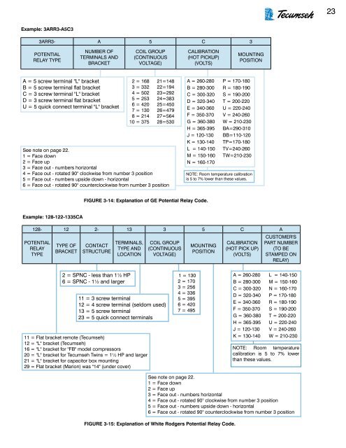
Example: 3ARR3-A5C3<br />
3ARR3- A 5 C 3<br />
POTENTIAL<br />
RELAY TYPE<br />
NUMBER OF<br />
TERMINALS AND<br />
BRACKET<br />
COIL GROUP<br />
(CONTINUOUS<br />
VOLTAGE)<br />
CALIBRATION<br />
(HOT PICKUP)<br />
(VOLTS)<br />
MOUNTING<br />
POSITION<br />
A = 5 screw terminal "L" bracket<br />
B = 5 screw terminal flat bracket<br />
C = 3 screw terminal "L" bracket<br />
D = 3 screw terminal flat bracket<br />
U = 5 quick connect terminal "L" bracket<br />
2 = 168<br />
3 = 332<br />
4 = 502<br />
5 = 253<br />
6 = 420<br />
7 = 130<br />
8 = 214<br />
10 = 375<br />
21=148<br />
22=194<br />
23=292<br />
24=383<br />
25=450<br />
26=479<br />
27=564<br />
28=530<br />
See note on page 22.<br />
1 = Face down<br />
2 = Face up<br />
3 = Face out - numbers horizontal<br />
4 = Face out - rotated 90° clockwise from number 3 position<br />
5 = Face out - numbers upside down - horizontal<br />
6 = Face out - rotated 90° counterclockwise from number 3 position<br />
A = 260-280<br />
B = 280-300<br />
C = 300-320<br />
D = 320-340<br />
E = 340-360<br />
F = 350-370<br />
G = 360-380<br />
H = 365-395<br />
J = 120-130<br />
K = 130-140<br />
L = 140-150<br />
M = 150-160<br />
N = 160-170<br />
P = 170-180<br />
R = 180-190<br />
S = 190-200<br />
T = 200-220<br />
U = 220-240<br />
V = 240-260<br />
W = 210-230<br />
BA=290-310<br />
BB=110-120<br />
TP=170-180<br />
TV=240-260<br />
TW=210-230<br />
NOTE: Room temperature calibration<br />
is 5 to 7% lower than these values.<br />
FIGURE 3-14: Explanation of GE Potential Relay Code.<br />
Example: 128-122-1335CA<br />
128- 12 2- 13 3 5 C A<br />
POTENTIAL<br />
RELAY<br />
TYPE<br />
TYPE OF<br />
BRACKET<br />
CONTACT<br />
STRUCTURE<br />
TERMINALS,<br />
TYPE AND<br />
LOCATION<br />
COIL GROUP<br />
(CONTINUOUS<br />
VOLTAGE)<br />
MOUNTING<br />
POSITION<br />
CALIBRATION<br />
(HOT PICK UP)<br />
(VOLTS)<br />
CUSTOMER'S<br />
PART NUMBER<br />
(TO BE<br />
STAMPED ON<br />
RELAY)<br />
2 = SPNC - less than 1½ HP<br />
6 = SPNC - 1½ and larger<br />
11 = 3 screw terminal<br />
12 = 4 screw terminal (seldom used)<br />
13 = 5 screw terminal<br />
23 = 5 quick connect terminals<br />
11 = Flat bracket remote (<strong>Tecumseh</strong>)<br />
12 = "L" bracket (<strong>Tecumseh</strong>)<br />
16 = "L" bracket for "FB" model compressors<br />
20 = "L" bracket for <strong>Tecumseh</strong> Twins = 1½ HP and larger<br />
21 = "L" bracket for capacitor box mounting<br />
29 = Flat bracket (Marion) was "14" (under cover)<br />
1 = 130<br />
2 = 170<br />
3 = 256<br />
4 = 336<br />
5 = 395<br />
6 = 420<br />
7 = 495<br />
A = 260-280<br />
B = 280-300<br />
C = 300-320<br />
D = 320-340<br />
E = 340-360<br />
F = 350-370<br />
G = 360-380<br />
H = 365-395<br />
J = 120-130<br />
K = 130-140<br />
L = 140-150<br />
M = 150-160<br />
N = 160-170<br />
P = 170-180<br />
R = 180-190<br />
S = 190-200<br />
T = 200-220<br />
U = 220-240<br />
V = 240-260<br />
W = 210-230<br />
NOTE: Room temperature<br />
calibration is 5 to 7% lower<br />
than these values.<br />
See note on page 22.<br />
1 = Face down<br />
2 = Face up<br />
3 = Face out - numbers horizontal<br />
4 = Face out - rotated 90° clockwise from number 3 position<br />
5 = Face out - numbers upside down - horizontal<br />
6 = Face out - rotated 90° counterclockwise from number 3 position<br />
FIGURE 3-15: Explanation of White Rodgers Potential Relay Code.