MANUAL rev 01 2005 eng LCA-D.pdf - Vetek Scales
MANUAL rev 01 2005 eng LCA-D.pdf - Vetek Scales
MANUAL rev 01 2005 eng LCA-D.pdf - Vetek Scales

Create successful ePaper yourself
Turn your PDF publications into a flip-book with our unique Google optimized e-Paper software.
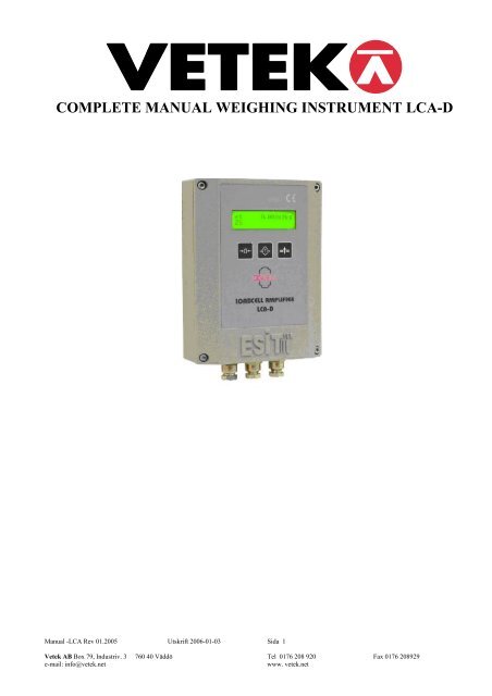
COMPLETE <strong>MANUAL</strong> WEIGHING INSTRUMENT <strong>LCA</strong>-D<br />
Manual -<strong>LCA</strong> Rev <strong>01</strong>.<strong>2005</strong> Utskrift 2006-<strong>01</strong>-03 Sida 1<br />
<strong>Vetek</strong> AB Box 79, Industriv. 3 760 40 Väddö Tel <strong>01</strong>76 208 920 Fax <strong>01</strong>76 208929<br />
e-mail: info@vetek.net<br />
www. vetek.net
CONTENTS<br />
1 OVERVIEW ....................................................................................... 4<br />
2 SPECIFICATIONS............................................................................ 5<br />
2.1 TECHNICAL SPECIFICATIONS ............................................. 5<br />
2.2 SYSTEM REQUIREMENTS ..................................................... 5<br />
2.3 ELECTRONICAL STRUCTURE .............................................. 6<br />
2.4 OPERATING SPECIFICATIONS ............................................. 7<br />
2.5 DISPLAY SPECIFICATIONS ................................................... 7<br />
2.6 CONTROL SPECIFICATIONS (OPTION) ............................... 8<br />
2.7 CERTIFICATES......................................................................... 8<br />
2.8 PHYSICAL DIMENSIONS........................................................ 9<br />
3 SCREEN APPEARANCE ............................................................... 10<br />
3.1 DISPLAY SYMBOLS.............................................................. 10<br />
3.2 KEYS........................................................................................ 10<br />
4 ASSEMBLING AND POWER-UP ................................................. 11<br />
4.1 START UP .................................................................................. 12<br />
4.2 INDICATOR VALUE RANGE ........................................................ 12<br />
4.3 ZERO PROCESS .......................................................................... 12<br />
4.4 AUTOMATIC ZERO ..................................................................... 12<br />
4.5 UNITS ........................................................................................ 12<br />
4.6 TARE (SEMI-AUTOMATIC TARE) ............................................... 13<br />
4.7 NUMERICAL TARE ..................................................................... 13<br />
4.8 DATE AND TIME ........................................................................ 13<br />
4.9 PROGRAM VERSION................................................................... 13<br />
5 SAFETY PRECAUTIONS .............................................................. 14<br />
6 <strong>LCA</strong> INDICATOR WORKING DIAGRAM................................. 15<br />
6.1 PARAMETERS AND THEIR MEANINGS ........................................ 16<br />
6.1.1 #IDENTITY:........................................................................ 16<br />
6.1.2 #DISPLAY SETUP:............................................................. 17<br />
6.1.3 #CALIBRATION: ............................................................... 20<br />
6.1.4 #INPUT SETUP:.................................................................. 21<br />
6.1.5 #OUTPUT SETUP:.............................................................. 25<br />
6.1.6 #COMM SETUP:................................................................. 27<br />
Manual -<strong>LCA</strong> Rev <strong>01</strong>.<strong>2005</strong> Utskrift 2006-<strong>01</strong>-03 Sida 2<br />
<strong>Vetek</strong> AB Box 79, Industriv. 3 760 40 Väddö Tel <strong>01</strong>76 208 920 Fax <strong>01</strong>76 208929<br />
e-mail: info@vetek.net<br />
www. vetek.net
6.2 WEIGHT CALIBRATION....................................................... 32<br />
6.2.1 PRE-ADJUSMENTS & GAIN SETUP ............................... 32<br />
6.2.2 ZERO CALIBRATION ....................................................... 33<br />
6.2.3 LOAD CALIBRATION....................................................... 34<br />
7 NORMAL WEIGHING................................................................... 35<br />
7.1 RESETTING SCREEN VALUE TO ZERO ........................................ 35<br />
7.2 ACTIVATING TARE .................................................................... 35<br />
7.3 DISABLING TARE VALUE........................................................... 35<br />
8 ERROR MESSAGES....................................................................... 36<br />
9 PROBLEMS AND SOLUTIONS.................................................... 37<br />
10 POWER SUPPLY SPECIFICATIONS..................................... 38<br />
11 OPERATING TEMPERATURE............................................... 38<br />
12 LOADCELL CONNECTION .................................................... 39<br />
13 COMMUNICATION CONNECTIONS.................................... 40<br />
14 OPTION ....................................................................................... 41<br />
14.1 ANALOG OUTPUT OPTION.................................................. 41<br />
14.2 RELAY OPTION...................................................................... 42<br />
15 PC SOFTWARES........................................................................ 44<br />
16 DIGITAL LINEARIZATION.................................................... 46<br />
17 TEMPERATURE COMPENSATION ...................................... 47<br />
18 COMMUNICATION STRUCTURE......................................... 48<br />
18.1 PHYSICAL STRUCTURE....................................................... 48<br />
18.2 <strong>LCA</strong> INDICATOR RS485 SPECIFICATIONS.................................. 48<br />
18.2.1 DATA STRUCTURE ........................................................... 49<br />
18.2.2 APPLICATION LAYER ....................................................... 49<br />
19 TERMS......................................................................................... 51<br />
20 DRAWINGS................................................................................. 52<br />
Manual -<strong>LCA</strong> Rev <strong>01</strong>.<strong>2005</strong> Utskrift 2006-<strong>01</strong>-03 Sida 3<br />
<strong>Vetek</strong> AB Box 79, Industriv. 3 760 40 Väddö Tel <strong>01</strong>76 208 920 Fax <strong>01</strong>76 208929<br />
e-mail: info@vetek.net<br />
www. vetek.net
OVERVIEW<br />
<strong>LCA</strong> (Load Cell Amplifier) is a smart signal converter which is designed for harsh industrial environments. The<br />
most distinctive feature of <strong>LCA</strong> is, its ability to expose all of its parameters using the MODBUS protocol.<br />
Features:<br />
• High internal resolution<br />
• Digital filter<br />
• Linearization<br />
• Temperature compensation<br />
• ModBus protocol<br />
• Internal voltage supply circuitry is isolated from the external voltage supply<br />
• Isolated communication lines<br />
• Temperature sensor<br />
• LCD display<br />
• 2 relay outputs<br />
• 4-20mA Analog output module<br />
• Eeprom memory for user Set-Up and Calibration information.<br />
• 24-bits Resolution<br />
• MODBUS protocol<br />
• IP-66 protection class for industrial applications<br />
Manual -<strong>LCA</strong> Rev <strong>01</strong>.<strong>2005</strong> Utskrift 2006-<strong>01</strong>-03 Sida 4<br />
<strong>Vetek</strong> AB Box 79, Industriv. 3 760 40 Väddö Tel <strong>01</strong>76 208 920 Fax <strong>01</strong>76 208929<br />
e-mail: info@vetek.net<br />
www. vetek.net
1 SPECIFICATIONS<br />
1.1 TECHNICAL SPECIFICATIONS<br />
• Easily adjustable parameter and calibration menu by keypad<br />
• Up to 160 mV/V input range<br />
• Gain adjustment according to sensor output<br />
• Sense compensation<br />
• Works with 12-24 Volt supply (DC / AC)<br />
• Up to 8 Load cells are connectable<br />
• Industrial IP 66 protection class case<br />
• Remote control, parameter Set-Up and Calibration<br />
Model<br />
<strong>LCA</strong><br />
Input<br />
DC voltage: -1,60 Volt to 1,60 Volt<br />
A/D Speed (/second) 50<br />
Display Resolution 1/100.000<br />
Display<br />
LCD (2x16 character)<br />
Maximum Range 7 digit (-9999999 to +9999999)<br />
Communication RS-232C / RS-485 selectable<br />
Optional Futures 4-20mA analog output, 2 relay outputs<br />
Load cell Excitation 250mA (8 load cell) at 10 VDC<br />
Power Supply 12-24 Volt DC / AC<br />
Weighing Accuracy 10000d<br />
EMC<br />
EN 55<strong>01</strong>1:2002 Emission - Class,<br />
EN 455<strong>01</strong>:1992/AC:1993 Metrological<br />
Aspects of Non-Automatic weighing<br />
Instruments.<br />
Passed with tests; Electrostatic Discharges<br />
(ESD), Radiated AM Field, Electrical Fast<br />
Transient (EFT)/Burst Transients, Power<br />
Supply Voltage Variations, Dips and<br />
Interruptions by KEMA<br />
1.2 SYSTEM REQUIREMENTS<br />
A power supply and a sensor (Load cell) are required for standard connection. And additional modules for proper<br />
using;<br />
• JUNCTION BOX: If the system consists of more than one<br />
load cell, then a junction box is used for gathering the load cell outputs to the <strong>LCA</strong> device.<br />
• COMPUTER (PC): If a computer will be used for monitoring<br />
the measured value as indicator (in <strong>LCA</strong>-X model) or both PC and <strong>LCA</strong> device (in <strong>LCA</strong>-D model) will display the<br />
measured value, then a computer with standard configuration will be required.<br />
Minimum Configuration: P100MHz processor, 8Mb RAM, 500Mb hard-disc and at least an RS232 port.<br />
And also if there is a network system, a Network adapter is required to work with the Network workgroup.<br />
Manual -<strong>LCA</strong> Rev <strong>01</strong>.<strong>2005</strong> Utskrift 2006-<strong>01</strong>-03 Sida 5<br />
<strong>Vetek</strong> AB Box 79, Industriv. 3 760 40 Väddö Tel <strong>01</strong>76 208 920 Fax <strong>01</strong>76 208929<br />
e-mail: info@vetek.net<br />
www. vetek.net
(NOTE: According to the selected PC Software, minimum configuration can be changed. If there is only measurement<br />
transfer to the PC or user operations (Tare, Zero etc.) from <strong>LCA</strong> devices with PC program, minimum configuration and<br />
operation system is enough to execute. Otherwise if there is a data record, computer should work on power-on state<br />
continuously and automatically records the weighing data. For this reason, the PC should have the qualifications that can<br />
work with safety operating systems WinNT, Win2000 or similar and enough hard-disc capability.)<br />
• RS232/485 CONVERTER: If RS-485 communication base will be used for communication an RS232/485<br />
Converter must be used between PC and device(s) to adapt device(s) and computer.<br />
(NOTE: To communicate with more than one device at the same bus, RS-485 Communication must be used.<br />
Furthermore, because of long distance between devices and PC, RS-485 communication must be used. For 0-50 meters<br />
RS-232, more than 50 meters RS-485 communication must be preferred)<br />
1.3 ELECTRONICAL STRUCTURE<br />
<strong>LCA</strong> indicator uses 16-bit PIC 18C252 IC micro controller that has 16 kWord (32 kByte) ROM memory and<br />
1532 bytes RAM. There is an Eeprom memory (2048 byte) for user setup and calibration history information. All<br />
calibration parameters and digital linearization and compensation tables are kept in this memory.<br />
There is a key place inside of <strong>LCA</strong> indicator. When the jumper on state, the key is short circuited, calibration and<br />
related parameters can be changed. When the jumper is open circuited then calibration and related parameter setups are<br />
prohibited (Other optional parameters can be changed any time).<br />
After calibration and parameter set-up, this jumper should be left in open-circuit state. This protection key is placed<br />
inside of <strong>LCA</strong> device and the cover must be unlocked to short-circuit this jumper.<br />
Manual -<strong>LCA</strong> Rev <strong>01</strong>.<strong>2005</strong> Utskrift 2006-<strong>01</strong>-03 Sida 6<br />
<strong>Vetek</strong> AB Box 79, Industriv. 3 760 40 Väddö Tel <strong>01</strong>76 208 920 Fax <strong>01</strong>76 208929<br />
e-mail: info@vetek.net<br />
www. vetek.net
1.4 OPERATING SPECIFICATIONS<br />
• Following functions can be adjusted by keypad.<br />
1. Accessing to the device identity information.<br />
2. Screen parameters can be changed.<br />
3. Calibration process can be done.<br />
4. Digital filtering and communication parameters can be adjusted.<br />
5. Zero and Tare operations can be done.<br />
• No-motion detection.<br />
• Center of Zero detection.<br />
• Warning above maximum allowable value and other error conditions (Related error message appears on the<br />
screen, “ErrXX”).<br />
• All parameters and calibration process can be changed from remote point.<br />
1.5 DISPLAY SPECIFICATIONS<br />
• LCD screen shows the following data:<br />
1. 7 digit measurement result<br />
2. Net/Gross symbol (N-0.000050kg)<br />
3. Tare value (T 1.000000 )<br />
4. Relay state (1, 2)<br />
5. Level of scaling ( e1 / e2 )<br />
6. No-motion state ( S )<br />
7. Center-of-Zero ( Z )<br />
• Displaying measurement with decimal point (1.000000kg)<br />
• Wide view angle screen<br />
• LCD backlighting<br />
Manual -<strong>LCA</strong> Rev <strong>01</strong>.<strong>2005</strong> Utskrift 2006-<strong>01</strong>-03 Sida 7<br />
<strong>Vetek</strong> AB Box 79, Industriv. 3 760 40 Väddö Tel <strong>01</strong>76 208 920 Fax <strong>01</strong>76 208929<br />
e-mail: info@vetek.net<br />
www. vetek.net
1.6 CONTROL SPECIFICATIONS (OPTION)<br />
• 4-20 mA or 0-10V analog output (16 bits resolution)<br />
This module supplies self-calibrated adjustable current output. It can easily be configured for the required range.<br />
( See, 5.1.5 #OUTPUT SETUP)<br />
• Relay option<br />
<strong>LCA</strong> indicator has two optional relay outputs. Relay contacts can be adapted as NormallyClosed/NormallyOpen.<br />
( See, 5.1.5 #OUTPUT SETUP)<br />
• Digital Input<br />
<strong>LCA</strong> indicator has two optically isolated digital inputs. This feature is for proper using.<br />
CERTIFICATES<br />
<strong>LCA</strong> indicator passed KEMA EMC tests with success.<br />
Manual -<strong>LCA</strong> Rev <strong>01</strong>.<strong>2005</strong> Utskrift 2006-<strong>01</strong>-03 Sida 8<br />
<strong>Vetek</strong> AB Box 79, Industriv. 3 760 40 Väddö Tel <strong>01</strong>76 208 920 Fax <strong>01</strong>76 208929<br />
e-mail: info@vetek.net<br />
www. vetek.net
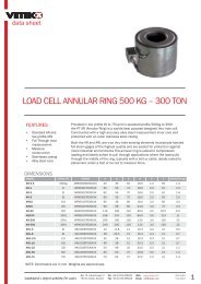
PHYSICAL DIMENSIONS<br />
Dimensions<br />
Width 130 mm<br />
Height 171 mm<br />
Depth 50 mm<br />
<strong>LCA</strong>-D<br />
Dimensions<br />
Width 130 mm<br />
Height 171 mm<br />
Depth 50 mm<br />
<strong>LCA</strong>-X<br />
Manual -<strong>LCA</strong> Rev <strong>01</strong>.<strong>2005</strong> Utskrift 2006-<strong>01</strong>-03 Sida 9<br />
<strong>Vetek</strong> AB Box 79, Industriv. 3 760 40 Väddö Tel <strong>01</strong>76 208 920 Fax <strong>01</strong>76 208929<br />
e-mail: info@vetek.net<br />
www. vetek.net
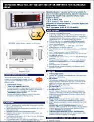
2 SCREEN APPEARANCE<br />
Level of scaling in Multi-<br />
Interval or Multi-Range<br />
(e1/e2)<br />
GROSS value. Shows the<br />
NET value with “N” symbol<br />
when Tare is active.<br />
Shows the unit of the<br />
measurement.<br />
(g, kg, lb, N, kN etc.)<br />
Rela<br />
y2<br />
State (2): This symbol appears on the screen when Relay2 is activated.<br />
2.1 DISPLAY SYMBOLS<br />
No-Motion (S): If there is<br />
stability on the platform, then ‘S’<br />
symbol appears on the screen.<br />
Center-of-Zero (Z): If<br />
displayed value is zero and the internal count is within<br />
±1/4d, ‘Z’ symbol appears on the screen.<br />
Relay1 State (1): This symbol appears on the<br />
screen when Relay1 is activated.<br />
Net (N): Appears on the screen when Tare is active. Notifies that displayed value is NET.<br />
Tare (T): Shows current Tare value.<br />
Shows the Tare value with “T” symbol,<br />
when Tare is active.<br />
Shows the activated<br />
relays.<br />
No-Motion symbol.<br />
(Stable)<br />
Center-of-Zero symbol.<br />
(Zero)<br />
Unit (g, kg, mV/V…):<br />
Shows the measurement unit in use. Can be changed in set-up menu.<br />
Scale Type (e1): Indicates that measured value is in first scale interval range when Scale Type is Multi-Interval<br />
or Multi-Range. (Not shown in Single-Interval mode)<br />
Scale Type (e2): Indicates that measured value is in second scale interval range when Scale Type is Multi-<br />
Interval or Multi-Range. (Not shown in Single-Interval mode)<br />
2.2 KEYS<br />
Zero Key:<br />
Tare Key:<br />
Makes screen value 0 (zero) if within allowable limits.<br />
Sets current screen value as Tare value or disables the p<strong>rev</strong>ious Tare value. Works as toggle.<br />
Function: If this button is pressed for 3 seconds or more, then Parameter Set-Up menu appears on the<br />
screen.<br />
( See. 5 <strong>LCA</strong> INDICATOR WORKING DIAGRAM)<br />
Manual -<strong>LCA</strong> Rev <strong>01</strong>.<strong>2005</strong> Utskrift 2006-<strong>01</strong>-03 Sida 10<br />
<strong>Vetek</strong> AB Box 79, Industriv. 3 760 40 Väddö Tel <strong>01</strong>76 208 920 Fax <strong>01</strong>76 208929<br />
e-mail: info@vetek.net<br />
www. vetek.net
3 ASSEMBLING and POWER-UP<br />
<strong>LCA</strong> Indicator has internal connection terminals. Relevant connections are done with these terminals. There is an<br />
explanation on the <strong>LCA</strong> board that represents the meaning of each terminal. Beginning with left side to right side on the<br />
<strong>LCA</strong> board (1 to 22) each terminal meaning is given below:<br />
1. POWER+ : Power Supply (+ Pin for DC Supply)<br />
2. POWER0 : Power Supply (– Pin for DC Supply)<br />
3. GROUND : Earth for device body.<br />
4. RS Rx/A : Rx pin for RS-232, A pin for RS-485<br />
5. RS Tx/B : Tx pin for RS-232, B pin for RS-485<br />
6. RELAY1 : Contact connection for Relay1.<br />
7. RELAYC : Common pin for both Relays.<br />
8. RELAY2 : Contact connection for Relay2.<br />
9. OUTPUT+ : Opto-isolated output (Opto-Collector)<br />
10. OUTPUT- : Opto isolated output (Opto-Emitter).<br />
11. INPUT1 : Digital input 1 (Opto isolated).<br />
12. INPUTC : Common pin for digital inputs.<br />
13. INPUT2 : Digital input 2 (Opto isolated).<br />
14. ANALOG+ : + Connection for 4-20 mA analog output.<br />
15. ANALOG- : – Connection for 4-20 mA analog output.<br />
16. SHIELD : Load cell ground connection (Same point with devices internal ground)<br />
17. –S : -Sense Load cell<br />
18. –E : -Excitation Load cell<br />
19. –I : -Input Load cell<br />
20. +S : +Sense Load cell<br />
21. +E : +Excitation Load cell<br />
22. +I : +Input Load cell<br />
It is enough to connect Power (1:Power+, 2:Power0) and Load cell (17..22, -S, -E, -I, +S, +E and +I) connections<br />
to device terminals for stand alone working as minimum requirements ( Section 1.2, MINIMUM REQUIREMENTS). When<br />
<strong>LCA</strong> device is first energized “ROM VERSION NO” appears on the screen and tests memory functions, then displays<br />
normal measurement screen.<br />
Manual -<strong>LCA</strong> Rev <strong>01</strong>.<strong>2005</strong> Utskrift 2006-<strong>01</strong>-03 Sida 11<br />
<strong>Vetek</strong> AB Box 79, Industriv. 3 760 40 Väddö Tel <strong>01</strong>76 208 920 Fax <strong>01</strong>76 208929<br />
e-mail: info@vetek.net<br />
www. vetek.net
3.1 Start Up<br />
When <strong>LCA</strong> is powered up, measured value appears on the screen. This value comes from p<strong>rev</strong>iously saved<br />
calibration and user zero point values. Also if there is a linearization and/or temperature compensation, screen value<br />
depends on these tables. Zero point moves to last saved user zero value.<br />
3.2 Indicator Value Range<br />
The result of the measurement can be from “–Max.-9e” to “Max.+9e” value (according to Gross value). If the<br />
screen value exceeds over these values then related screen message is shown (measured value will not be shown).<br />
3.3 Zero Process<br />
A new zero reference can be processed by pressing Zero key. Also screen value equals to zero and Center of Zero<br />
symbol (‘Z’) appears on the screen.<br />
Allowable Zero Limits: %4 of maximum value (OIML IR76, 4.5.1)<br />
Zero operation can only be set when screen value is GROSS. If there is a tared value (Screen showing Net value)<br />
then Zero process cannot be executed.<br />
3.4 Automatic Zero<br />
3.5 Units<br />
No permission to automatic zero.<br />
<strong>LCA</strong> indicator can be Set Up with different unit alternatives for the measured unit. This units are “kg”, “lb”,<br />
“t”, “g”, “oz”, “N”, “kN”, “mV/V”, “V” and “mb” ( See, 5.1.2 #DISPLAY SETUP). This Set Up can be done by keypad<br />
or by MODBUS.<br />
Manual -<strong>LCA</strong> Rev <strong>01</strong>.<strong>2005</strong> Utskrift 2006-<strong>01</strong>-03 Sida 12<br />
<strong>Vetek</strong> AB Box 79, Industriv. 3 760 40 Väddö Tel <strong>01</strong>76 208 920 Fax <strong>01</strong>76 208929<br />
e-mail: info@vetek.net<br />
www. vetek.net
3.6 Tare (Semi-Automatic Tare)<br />
Current screen value (Gross) becomes Tare value when Tare ( ) key pressed. If tare is active, ‘N’ symbol<br />
appears on the measurement screen, which indicates that the value on the screen is NET value. Tare value appears on the<br />
second line with ’T’ symbol.<br />
When Tare is active, if there is a stable condition with Net value (bigger than 1), Tare value will be set to zero<br />
after a zero or negative measurement (Gross) confirmed.<br />
NOTE: If screen value is unstable (There is a motion condition, no ‘S’ symbol) or screen value is negative, and then tare<br />
process is prohibited.<br />
Pressing Tare ( ) key again cancels Tare value.<br />
Tare operation can be done by MODBUS, too.<br />
3.7 Numerical Tare<br />
<strong>LCA</strong> indicator does not support getting known tare values from memory feature.<br />
3.8 Date and Time<br />
Production date, calibration date and number of calibration-processed information are kept in Eeprom memory.<br />
While during calibration process, calibrating PC program automatically saves the new calibration date to the memory.<br />
There is no Real Time Clock module inside of <strong>LCA</strong> devices.<br />
3.9 Program Version<br />
Program <strong>rev</strong>ision number appears on the screen when start-up occurs.<br />
Manual -<strong>LCA</strong> Rev <strong>01</strong>.<strong>2005</strong> Utskrift 2006-<strong>01</strong>-03 Sida 13<br />
<strong>Vetek</strong> AB Box 79, Industriv. 3 760 40 Väddö Tel <strong>01</strong>76 208 920 Fax <strong>01</strong>76 208929<br />
e-mail: info@vetek.net<br />
www. vetek.net
4 SAFETY PRECAUTIONS<br />
• After all connections are completed, power-up the device. Do not modify the current connections while device<br />
is powered up and working.<br />
• Please operate with the notified temperature ranges.<br />
• Always use the power supply given together with the indicator or a similar one with specifications.<br />
Manual -<strong>LCA</strong> Rev <strong>01</strong>.<strong>2005</strong> Utskrift 2006-<strong>01</strong>-03 Sida 14<br />
<strong>Vetek</strong> AB Box 79, Industriv. 3 760 40 Väddö Tel <strong>01</strong>76 208 920 Fax <strong>01</strong>76 208929<br />
e-mail: info@vetek.net<br />
www. vetek.net
5 <strong>LCA</strong> INDICATOR WORKING DIAGRAM<br />
If Function ( ) key is pressed for 3 seconds or more, then menu screen appears. There are six headline menus<br />
and they are as follows:<br />
• #IDENTITY<br />
• #DISPLAY SETUP<br />
• #CALIBRATION<br />
• #INPUT SETUP<br />
• #OUTPUT SETUP<br />
• #COMM SETUP<br />
Meaning of the keys (Exit Menu Enter) appears on the second line of screen when one of these headlines are<br />
listed. Menu screen looks like as follows:<br />
#IDENTITY<br />
Exit Menu Entr<br />
According to this logic, each key meaning is stated below.<br />
Exit: The Zero key is used. When this key is pressed, menu screen goes off and returns to normal<br />
measurement screen.<br />
Menu: The Tare key is used. Menu screen switches to next headline of menu when this button is pressed.<br />
(#IDENTITY, #DISPLAY<br />
SETUP, #CALIBRATION, #INPUT SETUP, #OUTPUT SETUP, COMM SETUP)<br />
Enter:<br />
is displayed.<br />
The Function key is used. When this key is pressed on the menu screen, related parameter setup screen<br />
One of these headlines can be selected by pressing Function ( ) key. Meaning of the parameter and<br />
parameter number that is to be modified or read from the screen, appears on the LCD’s upper line. The parameter’s<br />
alternatives or parameter value will be displayed on the second line of LCD. Related parameter digit blinks and helps us<br />
which digit is about to be changed.<br />
EXAMPLE:<br />
If parameter 16 (P16) “#INPUT SETUP”, “P16:Input Range” is wanted to be changed, then, first Function<br />
( ) key must be pressed for 3 seconds or more to enter the menu screen. Later, menu screen appears on the LCD as<br />
below:<br />
#IDENTITY<br />
Exit Menu Entr<br />
Pressing Tare (<br />
) key on this menu screen causes switching the other headlines. Switch to the #INPUT SETUP<br />
headline by pressing Tare (<br />
) key. Screen appearance will be as follows when this headline appeared on the screen:<br />
#INPUT SETUP<br />
Exit Menu Entr<br />
After then, enter to the parameter entry screen by pressing Function (<br />
) key. LCD appearance will be as below:<br />
Manual -<strong>LCA</strong> Rev <strong>01</strong>.<strong>2005</strong> Utskrift 2006-<strong>01</strong>-03 Sida 15<br />
<strong>Vetek</strong> AB Box 79, Industriv. 3 760 40 Väddö Tel <strong>01</strong>76 208 920 Fax <strong>01</strong>76 208929<br />
e-mail: info@vetek.net<br />
www. vetek.net
P16:Input Range<br />
1 2.50 mV/V<br />
The alternatives from 0 to 7 can be switched by pressing Zero (<br />
) key. Changeable parameter alternative blinks and<br />
the meaning of the alternative is seen next to the number. When Function ( ) key is pressed, selected parameter<br />
value is saved and parameter screen switches to the next parameter screen. The alternatives that belong to this parameter<br />
are:<br />
ALTERN MEANING<br />
0 1,25 mV/V<br />
1 2,50 mV/V<br />
2 5,00 mV/V<br />
3 10,0 mV/V<br />
4 20,0 mV/V<br />
5 40,0 mV/V<br />
6 80,0 mV/V<br />
7 160 mV/V<br />
5.1 Parameters and Their Meanings<br />
5.1.1 #IDENTITY:<br />
This headline contains some identity information about the device. These parameters are p<strong>rev</strong>iously generated<br />
values in the factory and each of these parameters cannot be change by keypad or ModBus. The topics included in this<br />
headline are; serial number, ROM version, number of calibration times, PC software version that used for calibration<br />
process and calibration date information. These are:<br />
P00:Serial Num:<br />
Shows the device’s serial number. Screen appearance will be as follows:<br />
P00:Serial Num<br />
0000<strong>01</strong>2 ─<br />
Since this is an unchangeable value, cursor blinks on the right bottom of the LCD.<br />
Passing to the next parameter screen is by pressing Function (<br />
) key.<br />
P<strong>01</strong>:ROM VERSION: Shows micro-controller’s software version. Screen appearance will be as follows:<br />
P<strong>01</strong>:Rom Version<br />
0000<strong>01</strong>0 ─<br />
Passing to the next parameter screen is by pressing Function ( ) key.<br />
P02:CustomerCode: Specific number for customers. Screen appearance will be as follows:<br />
P02:CustomerCode<br />
00000<strong>01</strong> ─<br />
Passing to the next parameter screen is by pressing Function (<br />
) key.<br />
P03:Calibr.Times: This information shows number of<br />
calibration done. (Automatically incremented when calibration is done). Screen appearance will be as follows:<br />
P03:Calibr.Times<br />
0000065 ─<br />
Passing to the next parameter screen is by pressing Function (<br />
) key.<br />
P04:PC Cal. Soft.: Personal code or PC software version number that the calibration process was made by.<br />
(The calibrating PC program automatically writes its own code to this area. If calibration is made by keypad, this value<br />
automatically sets itself to 0 [zero]). Screen appearance will be as follows:<br />
Manual -<strong>LCA</strong> Rev <strong>01</strong>.<strong>2005</strong> Utskrift 2006-<strong>01</strong>-03 Sida 16<br />
<strong>Vetek</strong> AB Box 79, Industriv. 3 760 40 Väddö Tel <strong>01</strong>76 208 920 Fax <strong>01</strong>76 208929<br />
e-mail: info@vetek.net<br />
www. vetek.net
P04:PC Cal. Soft<br />
00 ─<br />
Passing to the next parameter screen is by pressing Function (<br />
) key.<br />
P05:Calibr.Date: Calibration date information. The PC software that calibration made by, writes the<br />
calibration date to this area. If calibration process is made by keypad then this value will be displayed as “----“<br />
(unchangeable value). Screen appearance will be as follows:<br />
P05:Calibr. Date<br />
– – – – ─<br />
Passing to the next parameter screen is by pressing Function (<br />
returns to the headline screen)<br />
) key. (This is the last parameter screen. So, device<br />
5.1.2 #DISPLAY SETUP:<br />
This headline contains parameters about decimal point position, measurement unit, scale type, Max, Max1,<br />
Max2 and step (e1/e2) values.<br />
P06:Decimal Pt: Decimal point position adjustment. Maximum display value is 7 digit (9999999). According<br />
to this, alternatives are from 0 to 6.<br />
ALTERN MEANING<br />
0 9999999 (no decimal point)<br />
1 999999.9 (decimal point on 1 st digit)<br />
.. .. (………)<br />
6 9.999999 (decimal point on 6 th digit)<br />
(NOTE: Alternatives above 7 will not be displayed)<br />
Screen appearance will be as follows:<br />
P06:Decimal Pt<br />
2<br />
The digit, that is about to be changed, blinks for indicating the changeable value. The number on the flashing digit<br />
increases by pressing Zero ( ) key. Selected value is accepted by pressing Function ( ) key and next parameter<br />
screen is shown.<br />
P07:Unit Set: Measurement unit (g, kg, br, mV/V) for measured quantity. Alternatives from 0 to 9 and their<br />
meanings will be shown on the LCD screen. Screen appearance will be as follows:<br />
P07:Unit Set<br />
2 kg<br />
The new set value is blinks and meaning of the parameter is shown next to this value. The number on the flashing digit<br />
is increased by pressing Zero ( ) key. Alternatives and meanings are like as:<br />
ALTERN MEANING<br />
0 g<br />
1 kg<br />
2 t<br />
3 oz<br />
4 lb<br />
5 N<br />
6 kN<br />
7 mV/V<br />
8 V<br />
9 (no unit)<br />
Selected value is accepted by pressing Function (<br />
) key and next parameter screen is shown.<br />
P08:Scale Type: Scale Type for the measurement is determined in this parameter by choosing one of the<br />
alternatives from Single-Interval, Multi-Interval or Multi-Range. If there are two different steps for the measurement,<br />
selection must be Multi-Interval or Multi-Range. Screen appearance will be as follows:<br />
Manual -<strong>LCA</strong> Rev <strong>01</strong>.<strong>2005</strong> Utskrift 2006-<strong>01</strong>-03 Sida 17<br />
<strong>Vetek</strong> AB Box 79, Industriv. 3 760 40 Väddö Tel <strong>01</strong>76 208 920 Fax <strong>01</strong>76 208929<br />
e-mail: info@vetek.net<br />
www. vetek.net
P08:Scale Type<br />
0 Single<br />
The new set value blinks and meaning of the parameter shown next to this value. The number on the flashing digit is<br />
increased by pressing Zero ( ) key. Related alternatives and means are like as:<br />
ALTERN MEANING<br />
0 Single<br />
1 Mult Int<br />
2 Mult Rng<br />
As can be understood from the figure in above, when one of multi modes are used, measurement area can be<br />
evaluated as two different areas. According to this, passing value from 1 st area to 2 nd area is at “Max1+9e1”. As known<br />
in Single Mode, when the maximum (“Max+9e”) value exceeds then “Maximum” error message is displayed. In Multi<br />
modes, two different areas are separated with their own “Max” and “e” (Max1, e1 and Max2, e2) values. In Multi-<br />
Interval mode, e1 step value is valid from 0 (zero) to ‘Max1+9e1’ and from ‘Max1+9e1 to ‘Max2+9e2’ e2 step is valid.<br />
In Multi-Range mode: e1 step value is valid from 0 (zero) to ‘Max1+9e1’ and e2 step is valid from ‘Max1+9e1 to<br />
‘Max2+9e2’ too. But, there is no return from e2 to e1 on the ‘Max1+9e1’ value. Passing e2 step to e1 occurs when the<br />
screen value is Zero or negative (Absolute Zero).<br />
NOTE: If one of multi modes is chosen, Max1 and e1 alternatives are shown in the following parameter set up screens,<br />
too. If Single-Interval is chosen, then only Max (maximum value) and e (step) values are shown on the parameter Set-up<br />
menu.<br />
Selected value is accepted by pressing Function (<br />
) key and next parameter screen is shown.<br />
P09:(e1) Step: This step value is valid from 0 to “Max1+9e1” screen value (first-interval area) in Multi-<br />
Interval or Multi-Range selected measurements. Screen value increases or decreases with this step value. It can be 1, 2,<br />
5, 10, 20 or 50.<br />
If Single-Interval scale type is selected then this parameter screen message looks like “P09:(e ) Step” or if Multi-<br />
Interval or Multi-Range is selected then the screen message looks like “P09:(e1) Step”.<br />
Screen appearance will be as follows:<br />
P09:(e1) Step<br />
0 1<br />
The new set value blinks and meaning of the parameter is shown next to this value. The number on the flashing digit is<br />
increased by pressing Zero ( ) key. Related alternatives and means are like as:<br />
ALTERN MEANING<br />
0 1<br />
1 2<br />
2 5<br />
3 10<br />
4 20<br />
5 50<br />
Selected value is accepted by pressing Function (<br />
) key and next parameter screen is shown.<br />
Manual -<strong>LCA</strong> Rev <strong>01</strong>.<strong>2005</strong> Utskrift 2006-<strong>01</strong>-03 Sida 18<br />
<strong>Vetek</strong> AB Box 79, Industriv. 3 760 40 Väddö Tel <strong>01</strong>76 208 920 Fax <strong>01</strong>76 208929<br />
e-mail: info@vetek.net<br />
www. vetek.net
P10:Max1 Value: When the measurement area is evaluated as two different areas (Multi-Range or Multi-<br />
Interval), there is a transition value (Max1) from e1-paced area to e2-paced area. (This parameter setup menu will not<br />
shown in Single-Interval mode) Screen appearance will be as follows:<br />
P10:Max1 Value<br />
0<strong>01</strong>50.00 kg<br />
The new set value that is about to be changed blinks. The number on the flashing digit is increased by pressing<br />
Zero ( ) key. By pressing Tare ( ) key, flashing digit moves to the next digit. Measurement unit will be displayed<br />
on the right corner of LCD.<br />
Selected value is accepted by pressing Function (<br />
) key and next parameter screen is shown.<br />
P11:(e2) Step: Step value for Multi-Range and Multi-Interval modes in second interval area (1, 2, 5, 10, 20 or<br />
50). (If Single-Interval mode is selected then this parameter setup menu will not be displayed). Screen appearance will<br />
be as follows:<br />
P11:(e2) Step<br />
2 5<br />
The new set value blinks and meaning of the parameter is shown next to this value. The number on the flashing<br />
digit is increased by pressing Zero (<br />
) key.<br />
Selected value is accepted by pressing Function (<br />
) key and next parameter screen is shown.<br />
P12:Max2 Value: Maximum value. This is the maximum screen value that can be displayed for the<br />
measurement. If one of Multi modes are chosen then screen appearance will look like “P12:Max2 Value”, otherwise the<br />
screen appearance will look like “P12:Max Value”. Screen appearance will be as follows:<br />
P12:Max2 Value<br />
00500.00 kg<br />
The new set value that is about to be changed blinks. The number on the flashing digit can be increased by<br />
pressing Zero ( ) key. By pressing Tare ( ) key, flashing digit moves to the next digit. Measurement unit will be<br />
displayed on the right corner of LCD.<br />
Selected value is accepted by pressing Function (<br />
) key and next parameter screen is shown.<br />
Manual -<strong>LCA</strong> Rev <strong>01</strong>.<strong>2005</strong> Utskrift 2006-<strong>01</strong>-03 Sida 19<br />
<strong>Vetek</strong> AB Box 79, Industriv. 3 760 40 Väddö Tel <strong>01</strong>76 208 920 Fax <strong>01</strong>76 208929<br />
e-mail: info@vetek.net<br />
www. vetek.net
5.1.3 #CALIBRATION:<br />
In this menu calibration process is done. Also this screen can be used for monitoring internal counts. If you do<br />
not want to change anything then choose ‘No’ alternative, otherwise calibration can be modified or corrupted.<br />
P13:Set ZERO: In this section calibration zero is saved to the device non-volatile memory. On this parameter,<br />
screen appearance looks like as follows;<br />
P13:Set ZERO<br />
Yes 1476<br />
In this setup screen, “Yes” or “No” alternatives can be selected by pressing Zero (<br />
) key. Internal counts<br />
appear on the right bottom of LCD. Calibration Zero can be set by pressing Function ( ) key while “Yes”<br />
alternative is active on the screen. There will be no changes to Calibration Zero if “No” alternative on the screen.<br />
P14:Set LOAD: In this screen, calibrating value is determined. Screen appearance looks like as follows:<br />
P14:Set LOAD<br />
Yes 132476<br />
“Yes” or “No” alternatives can be selected by pressing Zero (<br />
) key. Internal counts appear on the right bottom of<br />
LCD. If Function ( ) key is pressed while “Yes” alternative is active on the screen the secondary calibration screen<br />
is displayed for calibration process. There is no change to the Calibration area if “No” alternative was selected<br />
(NOTE: If this parameter screen is passed with “No” selection, “P15:SCALE VALUE” menu will not be shown)<br />
Manual -<strong>LCA</strong> Rev <strong>01</strong>.<strong>2005</strong> Utskrift 2006-<strong>01</strong>-03 Sida 20<br />
<strong>Vetek</strong> AB Box 79, Industriv. 3 760 40 Väddö Tel <strong>01</strong>76 208 920 Fax <strong>01</strong>76 208929<br />
e-mail: info@vetek.net<br />
www. vetek.net
P15:SCALE VALUE: Determines the value that to is to be scaled as the reference value. Screen appearance<br />
will be as follows:<br />
P15:SCALE VALUE<br />
0<strong>01</strong>00.00 kg<br />
The new set value that is about to be changed blinks. The number on the flashing digit can be increased by<br />
pressing Zero ( ) key. By pressing Tare ( ) key, flashing digit moves to the next digit. Measurement unit appears<br />
on the right corner of LCD.<br />
On this screen, the value that is to be scaled is given for current internal counts. This is the value for the reference known<br />
value that the calibration is done.<br />
Selected value is accepted by pressing Function (<br />
) key. Calibration process is completed.<br />
EXAMPLE:<br />
After the calibration Zero is set, if there is a value like as above (‘132476’) on the screen, choosing “Yes”<br />
alternative and then pressing Function ( ) key, brings “P15:SCALE VALUE” to the screen. On this screen, setting<br />
“10000” as scaling value, means that calibrate this internal count (132476) to 10000 screen value.<br />
5.1.4 #INPUT SETUP:<br />
This menu item contains digital filtering, input range (mV/V) and temperature parameters.<br />
P16:Input Range: Determines input range (1,25 - 2,50 - ..160mV/V). Appropriate analogue input signal is chosen<br />
according to the sensor type. Screen appearance will be as follows:<br />
P16:Input Range<br />
<strong>01</strong>.25 mV<br />
The new set value blinks and meaning of the parameter is shown next to this value. The number on the flashing digit is<br />
increased by pressing Zero ( ) key. Related alternatives and means are as:<br />
ALTERN MEANING<br />
Manual -<strong>LCA</strong> Rev <strong>01</strong>.<strong>2005</strong> Utskrift 2006-<strong>01</strong>-03 Sida 21<br />
<strong>Vetek</strong> AB Box 79, Industriv. 3 760 40 Väddö Tel <strong>01</strong>76 208 920 Fax <strong>01</strong>76 208929<br />
e-mail: info@vetek.net<br />
www. vetek.net
0 1,25 mV/V<br />
1 2,50 mV/V<br />
2 5,00 mV/V<br />
3 10,0 mV/V<br />
4 20,0 mV/V<br />
5 40,0 mV/V<br />
6 80,0 mV/V<br />
7 160 mV/V<br />
Manual -<strong>LCA</strong> Rev <strong>01</strong>.<strong>2005</strong> Utskrift 2006-<strong>01</strong>-03 Sida 22<br />
<strong>Vetek</strong> AB Box 79, Industriv. 3 760 40 Väddö Tel <strong>01</strong>76 208 920 Fax <strong>01</strong>76 208929<br />
e-mail: info@vetek.net<br />
www. vetek.net
Selected value is accepted by pressing Function (<br />
) key and next parameter screen is shown.<br />
P17:Filter Size: Amount of measurement for arithmetical average calculation (0..3).<br />
Each A/D conversion result is kept in buffer memory for average calculation. According to this, amount of measurement<br />
can be changed by this parameter. Screen appearance will be as follows:<br />
P17:Filter Size<br />
3<br />
The new set value flashes and meaning of the parameter is shown next to this value. The number on the flashing digit is<br />
increased by pressing Zero ( ) key.<br />
(Buffer Size = 4x2^n, n: alternative)<br />
Related alternatives and means are as:<br />
ALTERN MEANING<br />
0 4 average<br />
1 8 average<br />
2 16 average<br />
3 32 average<br />
Selected value is accepted by pressing Function (<br />
) key and next parameter screen is shown.<br />
Manual -<strong>LCA</strong> Rev <strong>01</strong>.<strong>2005</strong> Utskrift 2006-<strong>01</strong>-03 Sida 23<br />
<strong>Vetek</strong> AB Box 79, Industriv. 3 760 40 Väddö Tel <strong>01</strong>76 208 920 Fax <strong>01</strong>76 208929<br />
e-mail: info@vetek.net<br />
www. vetek.net
P18:Flt.Toleranc: Amount of unstable internal counts for digital filtering can be determined with this<br />
parameter (0..9). Variations on internal counts can be compensated with this parameter. This parameter determines the<br />
permitted amount of internal counts between one after another measurement. The new measured value will be ignored<br />
when internal count value exceeds p<strong>rev</strong>ious value by this tolerance value. (Number of rejected measurements can be<br />
determined in “P19:Escape Count”)<br />
Screen appearance will be as follows:<br />
P18:Flt.Toleranc<br />
5<br />
The new set value blinks and the number on the flashing digit is increased by pressing Zero (<br />
( 8x2^n, n: Selected value)<br />
Related alternatives and means are like as:<br />
ALTERN MEANING<br />
0 8 count<br />
1 16 count<br />
2 32 count<br />
3 64 count<br />
4 128 count<br />
5 256 count<br />
6 512 count<br />
7 1024 count<br />
8 2048 count<br />
9 4096 count<br />
) key.<br />
Selected value is accepted by pressing Function (<br />
) key and next parameter screen is shown.<br />
P19:Escape Count: Number of measurements that is to be ignored when the measured value is over than the<br />
limit in parameter (“P18:Flt.Toleranc”). According to this value (0-.99), if following measurements exceeds the limit value<br />
then adapting to the new value is facilitated. This means, new screen value exists after this.<br />
This condition can be explained like as:<br />
There is a system with maximum 100kg capacity. Changing on the platform with 5kg weight will cause soft<br />
transition to the new value or fast response at once to the new value If fast response required than P18 and P19<br />
parameters must be set to smaller values. In this way, new value is ignored for a little time than buffered old values are<br />
cleared and adapted to the new value. Otherwise new measured values are kept on adding in the average buffer. In this<br />
way adapting to the new value is slower. Screen appearance will be as follows:<br />
P19:Escape Count<br />
05<br />
The new set value that is about to be changed blinks. The number on the flashing digit is increased by pressing<br />
Zero ( ) key. By pressing Tare ( ) key, flashing digit moves to the next digit. Selected value is accepted by<br />
pressing Function (<br />
) key and next parameter screen is shown.<br />
P33: Temp.Compens: This parameter determines whether the temperature compensation is ON or OFF<br />
(Yes/No). Temperature sensor can be activated by choosing the ‘Yes’ alternative. In this way current temperature value<br />
appears on the right corner of LCD. This parameter especially determines temperature compensation is operating on<br />
state or not. This means that digital compensation is on!!! Temperature compensation is a specific application for<br />
sensors and each sensor has its own multiplier constant values that is found during manufacturing. If current sensor is<br />
changed with a new one then the values used p<strong>rev</strong>iously become invalid. Be careful about the tables that temperature<br />
compensation uses. If you are not sure about your compensation table values, choose ‘No’ alternative. Screen<br />
appearance will be as follows:<br />
Manual -<strong>LCA</strong> Rev <strong>01</strong>.<strong>2005</strong> Utskrift 2006-<strong>01</strong>-03 Sida 24<br />
<strong>Vetek</strong> AB Box 79, Industriv. 3 760 40 Väddö Tel <strong>01</strong>76 208 920 Fax <strong>01</strong>76 208929<br />
e-mail: info@vetek.net<br />
www. vetek.net
P33:Temp.Compens<br />
Yes 39˚C<br />
In this setup screen, “Yes” or “No” alternative can be determined by pressing Zero (<br />
) key. Selected value is<br />
accepted by pressing Function (<br />
) key and next parameter screen is shown.<br />
5.1.5 #OUTPUT SETUP:<br />
This menu contains information about relay setting and 4-20 mA analog output setup.<br />
P20:SP1 NET/GRS: Set point 1 NET or GROSS. This parameter determines the value that used with Relay1 is<br />
NET value or GROSS value. If NET alternative is chosen then Relay1 is activated with respect to the NET value. Screen<br />
appearance will be as follows:<br />
P20:SP1 NET/GRS<br />
0 NET<br />
In this setup screen, alternatives can be changed by pressing Zero (<br />
ALTERN MEANING<br />
0 NET (Net value)<br />
1 GRS (Gross value)<br />
) key. Related alternatives and means are as:<br />
Selected value is accepted by pressing Function (<br />
) key and next parameter screen is shown.<br />
P21:SP1 Value: Set Point for Relay1 (7 digit). Screen appearance will be as follows:<br />
P21:SP1 Value<br />
00050.00 kg<br />
The new set value that is about to be changed blinks. The number on the flashing digit is increased by pressing<br />
Zero ( ) key. By pressing Tare ( ) key, flashing digit moves to the next digit. Measurement unit will be displayed<br />
on the right corner of LCD.<br />
Selected value is accepted by pressing Function (<br />
) key and next parameter screen is shown.<br />
P22:SP1 Abv/Belw: Activation condition for Relay1 is determined in this parameter screen. Relay1 can<br />
energize above the value that stated in “P21:SP1 Value” or below. Screen appearance will be as follows:<br />
P22:SP1 Abv/Belw<br />
0 Above<br />
Transition between alternatives can be done by pressing Zero (<br />
ALTERN MEANING<br />
0 Above (Above the Set value)<br />
1 Below (Below the Set value)<br />
) key. Related alternatives and means are like as:<br />
Selected value is accepted by pressing Function (<br />
) key and next parameter screen is shown.<br />
P23:SP2 NET/GRS: Set point 2 NET or GROSS. This parameter determines the value that used with Relay2 is<br />
NET value or GROSS value. If NET alternative chosen then Relay2 is energized with NET value. Screen appearance<br />
will be as follows:<br />
P23:SP2 NET/GRS<br />
0 NET<br />
In this setup screen, alternatives can be changed by pressing Zero (<br />
ALTERN MEANING<br />
0 NET (Net value)<br />
1 GRS (Gross value)<br />
) key. Related alternatives and means are like as:<br />
Selected value is accepted by pressing Function (<br />
) key and next parameter screen is shown.<br />
Manual -<strong>LCA</strong> Rev <strong>01</strong>.<strong>2005</strong> Utskrift 2006-<strong>01</strong>-03 Sida 25<br />
<strong>Vetek</strong> AB Box 79, Industriv. 3 760 40 Väddö Tel <strong>01</strong>76 208 920 Fax <strong>01</strong>76 208929<br />
e-mail: info@vetek.net<br />
www. vetek.net
P24:SP2 Value: Set Point for Relay1 (7 digit). Screen appearance will be as follows:<br />
P24:SP2 Value<br />
00250.00 kg<br />
The new set value that is about to be changed blinks. The number on the flashing digit is increased by pressing<br />
Zero ( ) key. By pressing Tare ( ) key, flashing digit moves to the next digit. Measurement unit will be displayed<br />
on the right corner of LCD.<br />
Selected value is accepted by pressing Function (<br />
) key and next parameter screen is shown.<br />
P25:SP2 Abv/Belw : Activation condition for Relay2 is determined in this parameter screen. Relay2 can<br />
energize above the value that stated in “P24:SP2 Value” or below. Screen appearance will be as follows:<br />
P25:SP2 Abv/Belw<br />
0 Above<br />
Transition between alternatives can be done by pressing Zero (<br />
ALTERN MEANING<br />
0 Above (Above the Set value)<br />
1 Below (Below the Set value)<br />
) key. Related alternatives and means are like as:<br />
Selected value is accepted by pressing Function (<br />
) key and next parameter screen is shown.<br />
P26:SP Delay: 100ms sensitive delay for Relays. Up to 25.5 second can be determined with this parameter<br />
(00.0-25.5 sc). Screen appearance will be as follows:<br />
P26:SP Delay<br />
00.5 sc<br />
The new set value that is about to be changed blinks. The number on the flashing digit is increased by pressing Zero<br />
( ) key. By pressing Tare ( ) key, flashing digit moves to the next digit. Unit of value will be displayed on the<br />
right corner of LCD.<br />
Selected value is accepted by pressing Function (<br />
) key and next parameter screen is shown.<br />
P27:AN Net/Gross : Analog output (4-20 mA) can work according to GROSS or NET value. Screen<br />
appearance will be as follows:<br />
P27:AN NET/GRS<br />
0 NET<br />
Alternatives can be changed by pressing Zero (<br />
ALTERN MEANING<br />
0 NET (Net value)<br />
1 GRS (Gross value)<br />
Selected value is accepted by pressing Function (<br />
) key. Related alternatives and means are like as:<br />
) key and next parameter screen is shown.<br />
P28:Analog From: Determines the analog outputs starting point (00,000...31,999 mA). When screen value is<br />
Zero (Net or Gross value, according to the selected value in “P27:AN Net/Gross”) then analog output value will be as stated<br />
in this parameter. Screen appearance will be as follows:<br />
P28:Analog From<br />
20.000 mA<br />
The new set value that is about to be changed blinks. The number on the flashing digit is increased by pressing Zero<br />
( ) key. By pressing Tare ( ) key, flashing digit moves to the next digit. Unit of value will be displayed on the<br />
right corner of LCD.<br />
Manual -<strong>LCA</strong> Rev <strong>01</strong>.<strong>2005</strong> Utskrift 2006-<strong>01</strong>-03 Sida 26<br />
<strong>Vetek</strong> AB Box 79, Industriv. 3 760 40 Väddö Tel <strong>01</strong>76 208 920 Fax <strong>01</strong>76 208929<br />
e-mail: info@vetek.net<br />
www. vetek.net
Selected value is accepted by pressing Function (<br />
) key and next parameter screen is shown.<br />
(This value (Analog From) is output when measured value is Zero (0) and must be less than “Analog To” value (Output<br />
when screen value is “Analog Maximum” that stated in parameter P30:Analog Max)<br />
P29:Analog To..: Determines the analog output end point (00,000...31,999 mA). When screen value is equal or<br />
greater than Analog Maximum value (P30:Analog Max) (Net or Gross value, according to the selected value in “P27:AN<br />
Net/Gross”) then analog output value will be as stated in this parameter. Screen appearance will be as follows:<br />
P29:Analog To..<br />
04.000 mA<br />
The new set value that is about to be changed blinks. The number on the flashing digit is increased by pressing Zero<br />
( ) key. By pressing Tare ( ) key, flashing digit moves to the next digit. Unit of value will be displayed on the<br />
right corner of LCD.<br />
Selected value is accepted by pressing Function (<br />
) key and next parameter screen is shown.<br />
Attention:<br />
These values can be set as:<br />
0 4 mA (Analog From)<br />
Analog Max 20 mA (Analog To)<br />
or,<br />
0 20 mA (Analog From)<br />
Analog Max<br />
4 mA (Analog To)<br />
P30:Analog Max: Maximum value for analog output. When screen value is equal or greater than “Analog<br />
Max” (Net or Gross value, according to the selected value in “P27:AN Net/Gross”) analog output value will be as stated in<br />
“P29:Analog To..”. Screen appearance will be as follows:<br />
P30:Analog Max<br />
<strong>01</strong>0.000 kg<br />
The new set value that is about to be changed blinks. The number on the flashing digit is increased by pressing<br />
Zero ( ) key. By pressing Tare ( ) key, flashing digit moves to the next digit. Measurement unit will be displayed<br />
on the right corner of LCD.<br />
Selected value is accepted by pressing Function (<br />
) key and next parameter screen is shown.<br />
5.1.6 #COMM SETUP:<br />
In this menu communication parameters can be set (ModBus ID, Protocol, baud rate, bits, parity, stop bits,<br />
response delay, timeout delay).<br />
P34:Modbus ID Nr: This value determines the device’s communication address on the communication line<br />
(Bus ID number). Can be set from 1 to 254.<br />
Attention: Number 0 and 255 are used for special applications.<br />
ModBus ID=0 Continuous Mode<br />
ModBus ID=255 Future Applications<br />
Screen appearance will be as follows:<br />
P34:Modbus ID Nr<br />
000<br />
If ID Number is set as 0, then signed (+,-) measured value is tranferred via the serial port continuously.<br />
Transmitting format is Ascii and finally “CR” (character 13) character is sent.<br />
For example transmitting the measured value as “1204kg” is transmitted like as:<br />
‘+’(43), ‘0’(48), ‘0’(48), ‘0’(48), ‘1’(49), ‘2’(50), ‘0’(48), ‘4’(52), chr(13 )<br />
Manual -<strong>LCA</strong> Rev <strong>01</strong>.<strong>2005</strong> Utskrift 2006-<strong>01</strong>-03 Sida 27<br />
<strong>Vetek</strong> AB Box 79, Industriv. 3 760 40 Väddö Tel <strong>01</strong>76 208 920 Fax <strong>01</strong>76 208929<br />
e-mail: info@vetek.net<br />
www. vetek.net
P34:Modbus ID<br />
255<br />
If ID Number=255 then communication parameters are forced to work with known parameters 1200,n,8b,1s in<br />
RTU protocol.<br />
The new set value that is about to be changed blinks. The number on the flashing digit is increased by pressing Zero<br />
( ) key. By pressing Tare ( ) key, flashing digit moves to the next digit. Unit of value will be displayed on the<br />
right corner of LCD.<br />
Selected value is accepted by pressing Function (<br />
) key and next parameter screen is shown.<br />
P35:CommProtocol: Protocol selection for Modbus communication mode.<br />
(NOT: If Modbus ID Number was selected as 0 (continuous mode) then this parameter screen is not shown.)<br />
Screen appearance will be as follows:<br />
P35:CommProtocol<br />
0 R<br />
Alternatives can be changed by pressing Zero (<br />
ALTERN MEANING<br />
0 R (RTU mode)<br />
1 A (ASCII mode)<br />
) key. Related alternatives and means are as:<br />
In shortly, according to MODBUS protocol: there are two ASCII character represents to a byte in ASCII mode. For<br />
example character 0hAF in hex denoted, is transmitted as ‘A’ and ‘F’ characters and their start-stop characters in ASCII<br />
mode. In RTU mode, each byte is treated as one byte. For example character 0hAF is transmitted as 0xAF<br />
(decimal175) and there are no start or stop characters in RTU mode. Determining start and stop conditions for<br />
MODBUS frames, timing between one data after another is checked.<br />
(examine MODBUS protocol for RTU and ASCII concepts.)<br />
Selected value is accepted by pressing Function (<br />
) key and next parameter screen is shown.<br />
P36:Baudrate: Communication speed selection (1200..9600). It is recommended to use lower speeds for long<br />
distances and noisy interfaces.<br />
Screen appearance will be as follows:<br />
P36:Baudrate<br />
0 1200<br />
Alternatives can be changed by pressing Zero (<br />
ALTERN MEANING<br />
0 1200<br />
1 2400<br />
2 4800<br />
3 9600<br />
Selected value is accepted by pressing Function (<br />
) key. Related alternatives and means are:<br />
) key and next parameter screen is shown.<br />
P37:Comm. Bits: Number of bits that to be used in communication (7bit/8bit).<br />
Screen appearance will be as follows:<br />
P37:Comm. Bits<br />
1 8b<br />
Alternatives can be changed by pressing Zero (<br />
ALTERN MEANING<br />
0 7b<br />
1 8b<br />
Selected value is accepted by pressing Function (<br />
) key. Related alternatives and means are like as:<br />
) key and next parameter screen is shown.<br />
Manual -<strong>LCA</strong> Rev <strong>01</strong>.<strong>2005</strong> Utskrift 2006-<strong>01</strong>-03 Sida 28<br />
<strong>Vetek</strong> AB Box 79, Industriv. 3 760 40 Väddö Tel <strong>01</strong>76 208 920 Fax <strong>01</strong>76 208929<br />
e-mail: info@vetek.net<br />
www. vetek.net
P38:Comm. Parity: Communication parity bit selection (none, even, odd parity)<br />
Screen appearance will be as follows:<br />
P38:Comm.Parity<br />
0 n<br />
Alternatives can be changed by pressing Zero (<br />
ALTERN MEANING<br />
0 n (no parity)<br />
1 o (odd parity)<br />
2 e (even parity)<br />
Selected value is accepted by pressing Function (<br />
) key. Related alternatives and means are as:<br />
) key and next parameter screen is shown.<br />
Manual -<strong>LCA</strong> Rev <strong>01</strong>.<strong>2005</strong> Utskrift 2006-<strong>01</strong>-03 Sida 29<br />
<strong>Vetek</strong> AB Box 79, Industriv. 3 760 40 Väddö Tel <strong>01</strong>76 208 920 Fax <strong>01</strong>76 208929<br />
e-mail: info@vetek.net<br />
www. vetek.net
P39:Comm. Stop: Communication stop bit selection (1stop, 2stop).<br />
Screen appearance will be as follows:<br />
P39:Comm. Stop<br />
0 1s<br />
Alternatives can be changed by pressing Zero (<br />
ALTERN MEANING<br />
0 1s (1 stop)<br />
1 2s (2 stop)<br />
Selected value is accepted by pressing Function (<br />
) key. Related alternatives and means are as:<br />
) key and next parameter screen is shown.<br />
P40:Resp. Delay: Response delay.<br />
Screen appearance will be as follows:<br />
P40:Resp. Delay<br />
008 ms<br />
The new set value that is about to be changed blinks. The number on the flashing digit is increased by pressing Zero<br />
( ) key. By pressing Tare ( ) key, flashing digit moves to the next digit. Unit of value will be displayed on the<br />
right corner of LCD.<br />
The values that are available in the parameter are:<br />
0..255ms in 1200 baud (max 255ms),<br />
0..127ms in 2400 baud (max 127ms),<br />
0.. 63ms in 4800 baud (max 63ms),<br />
0.. 31ms in 9600 baud (max 31ms).<br />
If the value that is to be adjusted for this parameter is over than maximum value than screen appearance will be as<br />
follows:<br />
Err:Resp. Delay<br />
008 ms<br />
In this case the value that entered must be changed with a valid value.<br />
Selected value is accepted by pressing Function (<br />
) key and next parameter screen is shown.<br />
P41:TimeOut Dly.: Timeout delay. When there is an error in communication, device waits for time out delay<br />
to end and then prepares communication to ready state. Screen appearance will be as follows:<br />
P41:TimeOut Dly.<br />
008 ms<br />
The new set value that is about to be changed blinks. The number on the flashing digit is increased by pressing Zero<br />
( ) key. By pressing Tare ( ) key, flashing digit moves to the next digit. Unit of value will be displayed on the<br />
right corner of LCD.<br />
The values that available in parameter are:<br />
12..255ms in 1200 baud (max 255ms),<br />
6...127ms in 1200 baud (max 127ms),<br />
3.....63ms in 1200 baud (max 63ms),<br />
2.....31ms in 1200 baud (max 31ms)<br />
If the value that to be adjusted for this parameter is over than maximum value than screen appearance will be as follows:<br />
Err:TimeOut Dly.<br />
008 ms<br />
In this case the value that entered must be changed with a valid value.<br />
Selected value is accepted by pressing Function (<br />
) key and next parameter screen is shown.<br />
Manual -<strong>LCA</strong> Rev <strong>01</strong>.<strong>2005</strong> Utskrift 2006-<strong>01</strong>-03 Sida 30<br />
<strong>Vetek</strong> AB Box 79, Industriv. 3 760 40 Väddö Tel <strong>01</strong>76 208 920 Fax <strong>01</strong>76 208929<br />
e-mail: info@vetek.net<br />
www. vetek.net
#IDENTITY<br />
P00:Serial Num<br />
|<br />
P<strong>01</strong>:Rom Version<br />
|<br />
P02:Customer Code<br />
|<br />
P03:Calibr. Times<br />
P04:PC Cal.. Soft<br />
|<br />
P05:Calibr.Date<br />
#DISPLAY SETUP<br />
P06:Decimal Pt<br />
|<br />
P07:Unit Set<br />
|<br />
P08:Scale Tpe<br />
|<br />
P09:(e1) Step<br />
P10:Max1 Value<br />
|<br />
P11:(e2) Step<br />
|<br />
P12:Max2 Value<br />
#CALIBRATION<br />
P13:Set ZERO<br />
|<br />
P14:Set LOAD<br />
P15:Scale Value<br />
#INPUT SETUP<br />
P16:Input Range<br />
|<br />
P17:Filter Size<br />
|<br />
P18:Flt.Toleranc<br />
|<br />
P19:Escape Count<br />
P33:Temp.Compens<br />
#OUTPUT SETUP<br />
P20:SP1 NET/GRS<br />
|<br />
P21:SP1 Value<br />
P22:SP1 Abv/Belw<br />
|<br />
P23:SP2 NET/GRS<br />
P24:SP2 Value<br />
|<br />
P25:SP2 Abv/Belw<br />
|<br />
P26:SP Delay<br />
|<br />
P27:AN Net/Gross<br />
|<br />
P28:Analog From<br />
|<br />
P29:Analog To..<br />
P30:Analog Max<br />
#COMM SETUP<br />
P34:Modbus ID Nr<br />
|<br />
P35:CommProtocol<br />
|<br />
P36:Baudrate<br />
|<br />
P37:Comm. Bits<br />
P38:Comm. Parity<br />
|<br />
P39:Comm. Stop<br />
|<br />
P40:Resp. Delay<br />
|<br />
P41:TimeOut. Dly.<br />
|<br />
|<br />
|<br />
|<br />
|<br />
|<br />
|<br />
|<br />
|<br />
|<br />
|<br />
|<br />
Manual -<strong>LCA</strong> Rev <strong>01</strong>.<strong>2005</strong> Utskrift 2006-<strong>01</strong>-03 Sida 31<br />
<strong>Vetek</strong> AB Box 79, Industriv. 3 760 40 Väddö Tel <strong>01</strong>76 208 920 Fax <strong>01</strong>76 208929<br />
e-mail: info@vetek.net<br />
www. vetek.net
5.2 WEIGHT CALIBRATION<br />
Follow the topics arranged below for performing calibration process correctly:<br />
• After all connections have been done, the indicator should be kept in power for at least 10 minutes before<br />
starting calibration process.<br />
• If possible, during this wait time, load and unload the weight for a few times.<br />
• Keep away all obstacles that may p<strong>rev</strong>ent load to be sensed by the platform.<br />
• The reference weight should better be approved by. authorities.<br />
• The calibration weight should better be at least half of the capacity.<br />
5.2.1 PRE-ADJUSMENTS & GAIN SETUP<br />
According to the sensor type (load cell) Input Voltage Range and digital filtering parameters should be set before<br />
the calibration process. For doing this, first enter the menu screen by pressing Function (<br />
) key for 3 seconds or<br />
more, then menu screen appears. And then switch to the “#INPUT SETUP” menu by pressing Tare (<br />
) key. Entering<br />
this menu headline is done pressing Function ( ) key.<br />
In this menu;<br />
• P16:Input Range: Input Voltage Range should be selected according to the sensor (load cell) type.<br />
Alternatives can be changed and displayed by pressing Zero (<br />
) key. Selected value accepted by pressing<br />
Function ( ) key and next parameter screen is shown.<br />
For example, if a load cell that 2 mV/V output ranged is used, then ‘1 2.50 mV/V’ alternative should be selected.<br />
• P17:Filter Size: Buffer size for average calculation. ‘0’ means 4, ‘1’ means 8, ‘2’ means 16 and ‘3’ means 32<br />
measurements will be added in for the average calculation. ( See. 6.1.4 #INPUT SETUP). It is recommended to<br />
choose ‘3’ (32 measurements) value for this parameter. Alternatives can be changed and displayed by pressing<br />
Zero ( ) key. Selected value accepted by pressing Function ( ) key and next parameter screen is shown.<br />
• P18:Flt.Toleranc: Permission to the unstable situation for internal counts. If the weight on the platform is<br />
unstable (in motion) this causes movement on the internal count. This situation can be eliminated by selecting<br />
suitable alternative ( See. 6.1.4 #INPUT SETUP). If ‘6’ is selected then it means over 512 counts will be<br />
rejected. If this situation occurs one after another, this means that the measured value is a new value. Because<br />
of this, the parameter that is determined in P19 (P19:Escape Counts) notifies how many times this overcome<br />
should occur before the averaging restarts.<br />
• P19:Escape Counts: Determines the difference between internal counts exceeding permissible value come in<br />
series.<br />
NOT: If you have no idea about this process, it is better to set this value as ‘5’.<br />
• P33:Temp.Compens: Determines whether the temperature compensation is On or Off state. While doing<br />
calibration process, defined temperature constants and temperature curve for the sensor (each load cell has<br />
different constant and curve) are saved to the non-volatile memory. Because of this reason if you not sure about<br />
this process, please choose ‘No’ alternative for this parameter!<br />
Manual -<strong>LCA</strong> Rev <strong>01</strong>.<strong>2005</strong> Utskrift 2006-<strong>01</strong>-03 Sida 32<br />
<strong>Vetek</strong> AB Box 79, Industriv. 3 760 40 Väddö Tel <strong>01</strong>76 208 920 Fax <strong>01</strong>76 208929<br />
e-mail: info@vetek.net<br />
www. vetek.net
5.2.2 ZERO CALIBRATION<br />
In order to introduce the Zero point value to the device, Zero Calibration is done. To attain the<br />
“#CALIBRATION” menu, press Tare (<br />
) key on the menu screen and then enter the sub-menu items under the<br />
“#CALIBRATION” menu by pressing Function (<br />
) key. Screen appearance will be as follows:<br />
P13:Set ZERO<br />
Yes 1476<br />
In this setup screen, “Yes” or “No” alternative can be determined by pressing Zero (<br />
) key. Internal counts<br />
appear on the right bottom of LCD. Calibration Zero is done by pressing Function ( ) key while “Yes” alternative<br />
is active on the screen. There are no changes to Calibration Zero if “No” alternative on the screen.<br />
Manual -<strong>LCA</strong> Rev <strong>01</strong>.<strong>2005</strong> Utskrift 2006-<strong>01</strong>-03 Sida 33<br />
<strong>Vetek</strong> AB Box 79, Industriv. 3 760 40 Väddö Tel <strong>01</strong>76 208 920 Fax <strong>01</strong>76 208929<br />
e-mail: info@vetek.net<br />
www. vetek.net
5.2.3 LOAD CALIBRATION<br />
In order to introduce known value to the device LOAD CALIBRATION should be performed. On this<br />
parameter screen appearance looks as:<br />
P14:Set LOAD<br />
Yes 132476<br />
Set (or load) your sensor with a known value. And then select ‘Yes’ by pressing Zero ( ) key. Internal count that<br />
represents the load on sensor appears on the right bottom of LCD. To continue the calibration progress press Function<br />
( ) key. Finally scaling value screen appears on the LCD. In this screen, calibrating value is written.<br />
P15:SCALE VALUE<br />
0<strong>01</strong>0000 g<br />
The new set value that is about to be changed blinks. The number on the flashing digit is increased by pressing Zero<br />
( ) key. By pressing Tare ( ) key, flashing digit moves to the next digit. Unit of value will be displayed on the<br />
right corner of LCD.<br />
Selected value is accepted by pressing Function (<br />
) key and next parameter screen is shown.<br />
Make sure to keep the platform (sensor set value) in stable condition.<br />
EXAMPLE:<br />
After the zero calibration is finished, choosing ‘Yes’ alternative with 132476 screen value and then entering<br />
10000 as scale value on “P15:SCALE VALUE” screen, means that calibrate the screen value for 132476 internal count to<br />
the 10000 screen value.<br />
Manual -<strong>LCA</strong> Rev <strong>01</strong>.<strong>2005</strong> Utskrift 2006-<strong>01</strong>-03 Sida 34<br />
<strong>Vetek</strong> AB Box 79, Industriv. 3 760 40 Väddö Tel <strong>01</strong>76 208 920 Fax <strong>01</strong>76 208929<br />
e-mail: info@vetek.net<br />
www. vetek.net
6 NORMAL WEIGHING<br />
To return to the normal measurement screen, press Zero (<br />
) key when menu screen is active. In the menu screen,<br />
each key’s meaning explained under the upper side of keys. Therefore “Exit” operation is represented with Zero ( )<br />
key. <strong>LCA</strong> device’s ROM version number is shown on LCD screen for a while and then starts to operate with normal<br />
measurement mode when <strong>LCA</strong> is powered up.<br />
6.1 Resetting Screen Value to Zero<br />
To reset screen value to zero, Zero ( ) key is pressed. In order to perform this function, the indicator should<br />
be in no-motion (stable) state which can be realized with the “S” symbol on the LCD. And also Tare is not active.<br />
Permission for zeroing screen value is limited with %4 of Maximum capacity. Otherwise an error message appears on<br />
the screen (See. Error Messages, ERROR-3,ZERO LIMIT).<br />
After the zero has been set, the Center-of-Zero point sign (“Z”) appears on the left side of LCD.<br />
6.2 Activating Tare<br />
Tare ( ) key is pressed to make the screen value as Tare value. When there is an unstable condition (There is<br />
no “S” symbol on the screen) this key is ignored. When Tare is activated, the display value will be zero and tared value<br />
is shown on the second line of LCD with “T” symbol. Also “N” symbol appears on the front of screen value. This<br />
means, measured value is Net value.<br />
• In order to Tare a value, the screen value must be positive.<br />
(There is no permission to Tare with negative value and if there is a tared value then there is no zeroing operation)<br />
• When Tare is active, Zero key is ignored.<br />
6.3 Disabling Tare Value<br />
Pressing Tare ( ) key again while Tare is active, will disable the Tare function. When tare is not active “T”<br />
symbol and tared value on the second line of LCD goes off. The value on the screen is now Gross value.<br />
Manual -<strong>LCA</strong> Rev <strong>01</strong>.<strong>2005</strong> Utskrift 2006-<strong>01</strong>-03 Sida 35<br />
<strong>Vetek</strong> AB Box 79, Industriv. 3 760 40 Väddö Tel <strong>01</strong>76 208 920 Fax <strong>01</strong>76 208929<br />
e-mail: info@vetek.net<br />
www. vetek.net
7 ERROR MESSAGES<br />
Because of wrong usage or some error conditions <strong>LCA</strong> device displays the following messages:<br />
ERROR-3<br />
"ZERO LIMIT"<br />
Cannot perform Zeroing. This value cannot be set to zero by pressing Zero ( ) key. Because, there<br />
is a limitation for zeroing with maximum of %4. Can be done with Zero Calibration.<br />
ERROR-50<br />
ERROR-1<br />
"CALIB.KEY!"<br />
Calibration key is disabled. To perform this operation, modification should be done on the <strong>LCA</strong> board.<br />
"MAXIMUM!!!"<br />
Screen value is over. (Over than Max+9e, Max:Maximum capacity, e: step value)<br />
ERROR-22<br />
ERROR-90<br />
ERROR-5<br />
ERROR-91<br />
"Eeprom Mem"<br />
Non-volatile memory error. Please call service.<br />
"CONV.TOUT!"<br />
ADC conversion is timed out. Chip not responding. Please call service.<br />
"ADC RANGE!"<br />
Internal counts are in over state. Check ADC gain setup.<br />
"TEMP.TOUT!"<br />
Time out for temperature sensor. Not responding. Call service.<br />
ERROR-99 "WATCHDOG! "<br />
There is an unknown soft lock occurred and device automatically RESET itself.<br />
Manual -<strong>LCA</strong> Rev <strong>01</strong>.<strong>2005</strong> Utskrift 2006-<strong>01</strong>-03 Sida 36<br />
<strong>Vetek</strong> AB Box 79, Industriv. 3 760 40 Väddö Tel <strong>01</strong>76 208 920 Fax <strong>01</strong>76 208929<br />
e-mail: info@vetek.net<br />
www. vetek.net
8 PROBLEMS and SOLUTIONS<br />
<br />
☺<br />
<br />
☺<br />
<br />
☺<br />
<br />
☺<br />
<br />
☺<br />
Nothing on screen and no backlight.<br />
No energy is given to the device. The plug may be loose or power is off. Check the voltages.<br />
<strong>LCA</strong> can not communicate with electronic device connected (PC,PLC..).<br />
Check the communication parameters and cables. The parameters must be same configured with the<br />
electronic device that <strong>LCA</strong> is connected (Protocol, baudrate, bits, parity, stop bits and Modbus ID<br />
number must be same if works as Modbus Slave device).<br />
Check the cable and RS232/485 converter if used.<br />
Weight can not be seen.<br />
There can be a calibration error or wrong connection in Load-cell cable. May need to perform<br />
calibration again.<br />
Keys not functioning.<br />
Check whether any key is left pressed.<br />
Weight can not be reset to zero.<br />
If the no-motion state is not achieved and ‘S’ symbol is not the LCD screen then Zeroise operation can<br />
not be performed. Increase the Digital Filtering values or increase the step value. If zeroise operation<br />
can not perform while ‘S’ (stable) symbol on the LCD screen then Zero (<br />
service.<br />
) key is broken. Call<br />
Manual -<strong>LCA</strong> Rev <strong>01</strong>.<strong>2005</strong> Utskrift 2006-<strong>01</strong>-03 Sida 37<br />
<strong>Vetek</strong> AB Box 79, Industriv. 3 760 40 Väddö Tel <strong>01</strong>76 208 920 Fax <strong>01</strong>76 208929<br />
e-mail: info@vetek.net<br />
www. vetek.net
9 POWER SUPPLY SPECIFICATIONS<br />
VOLT POWER<br />
1 12V 5W<br />
2 24V 5W<br />
Use one of the specified power<br />
supplies for <strong>LCA</strong> indicator.<br />
Isolation voltage minimum 2000 V.<br />
10 Operating Temperature<br />
Temperature Range: -10..50 °C<br />
Manual -<strong>LCA</strong> Rev <strong>01</strong>.<strong>2005</strong> Utskrift 2006-<strong>01</strong>-03 Sida 38<br />
<strong>Vetek</strong> AB Box 79, Industriv. 3 760 40 Väddö Tel <strong>01</strong>76 208 920 Fax <strong>01</strong>76 208929<br />
e-mail: info@vetek.net<br />
www. vetek.net
11 LOADCELL CONNECTION<br />
There are two power lines and two output lines on the Load cell cables. Some load cells has additional sense lines.<br />
The colors on the Esit Load cell cables and meanings are explained as follows:<br />
For 6 wired load cell cable:<br />
COLOR<br />
Shield<br />
Red<br />
White<br />
Black<br />
Green<br />
Orange (Yellow) - Sense<br />
Blue<br />
MEANING<br />
Cover (Blendage, Shield)<br />
- Output<br />
+Output<br />
- Excitation<br />
+Excitation<br />
+Sense<br />
Load cell cables can be 4 wired or 6 wired. When 4 wired load cell cable used then there are no Sense Lines<br />
(Orange and Blue). Because of this, these pins on <strong>LCA</strong> terminal must be shorted with Power (Excitation) lines. [Jumper<br />
from +Sense (+S) to +Power (+E) and from –Sense (-S) to –Power (-E)]<br />
If the system consists of more than one load cell, then a junction box is used for gathering the load cell outputs<br />
to the <strong>LCA</strong> device.<br />
For 4 wired load cell cable:<br />
COLOR MEANING<br />
Shield Cover (Blendage, Shield)<br />
Red<br />
- Output<br />
White +Output<br />
Black - Excitation<br />
Green +Excitation<br />
After checking the correct connection is supplied, power up the device.<br />
Manual -<strong>LCA</strong> Rev <strong>01</strong>.<strong>2005</strong> Utskrift 2006-<strong>01</strong>-03 Sida 39<br />
<strong>Vetek</strong> AB Box 79, Industriv. 3 760 40 Väddö Tel <strong>01</strong>76 208 920 Fax <strong>01</strong>76 208929<br />
e-mail: info@vetek.net<br />
www. vetek.net
12 COMMUNICATION CONNECTIONS<br />
<strong>LCA</strong> Communication Line Connection (RS-232 standard);<br />
RS Rx/A<br />
Rx (Receive)<br />
RS Tx/B<br />
Tx (Transmit)<br />
GROUND<br />
Gnd<br />
<strong>LCA</strong> Communication Line Connection (RS-485 standard);<br />
RS Rx/A<br />
RS A (Master device, PC etc..)<br />
RS Tx/B<br />
RS B (Master device, PC etc..)<br />
Manual -<strong>LCA</strong> Rev <strong>01</strong>.<strong>2005</strong> Utskrift 2006-<strong>01</strong>-03 Sida 40<br />
<strong>Vetek</strong> AB Box 79, Industriv. 3 760 40 Väddö Tel <strong>01</strong>76 208 920 Fax <strong>01</strong>76 208929<br />
e-mail: info@vetek.net<br />
www. vetek.net
13 OPTION<br />
<strong>LCA</strong> device has a 4-20 mA analog output and two-relay outputs as optional alternatives.<br />
13.1 ANALOG OUTPUT OPTION<br />
<strong>LCA</strong> indicator has a 4-20 mA analog output as option. D/A module doesn’t need to be calibrated and offset<br />
adjusted. Analog output range can be adjusted for the required output range and can achieve 16 bit resolution.<br />
Adjusting 4-20 mA Module:<br />
At first, relational analog output parameter must be set correctly. For doing this, selection for NET or GROSS value<br />
(P27), start point of analog output (P28), end point for analog output (P29) and maximum value for Analog output<br />
(P30)should be done. Setting these parameters are shown below;<br />
Pressing Function (<br />
) key for 3 seconds or more, than menu screen will appear on the LCD. Switch to the<br />
“#OUTPUT SETUP” menu by pressing Tare ( ) key and then press Function ( ) key to enter this menu item.<br />
Skip parameters from P20 to P26 by pressing Function (<br />
) key.<br />
P27:AN NET/GRS: This parameter determines the analog output will reflect the Net or Gross value. Gross or<br />
Net alternative can be changed by pressing Zero (<br />
) key. ( See. 5.1.5 #OUTPUT SETUP)<br />
P28 :Analog From : When the screen value is Zero (According to the selection on P27: NET/GRS), this value<br />
will be output. This value can be set from 0.000 mA to 31.999 mA.<br />
( See. 5.1.5 #OUTPUT SETUP)<br />
P29 :Analog To.. : When the screen value is Maximum (P12 :Max Value), analog output will be as defined in this<br />
section.<br />
( See. 5.1.5 #OUTPUT SETUP)<br />
If an error or bigger value over than 31.999, entered values will not be saved and an error message (“Err”) will<br />
appear on the left corner of LCD. Screen appearance will be as follows:<br />
Err:Analog From<br />
32.000 mA<br />
The entered value should be corrected with true value.<br />
Example:<br />
If the required analog output is,<br />
15 mA for the “0“ screen value,<br />
5 mA for the “Analog Max“ screen value<br />
and analog output will reflect the Net value, than parameters should be adjusted as follows;<br />
(Analog Max value that can be found in P30 represents the Max value for 4/20mA output)<br />
P27:AN Gross/Net; 0Nt<br />
P28:Analog From; 15.000 mA<br />
P29:Analog To..: 05.000 mA<br />
NOT:<br />
Analog output setup can be done as,<br />
0 4 mA (Analog From)<br />
Analog Max 20 mA (Analog To.. ),<br />
And also can be done as,<br />
0 20 mA (Analog From)<br />
Analog Max 4 mA (Analog To.. )<br />
Manual -<strong>LCA</strong> Rev <strong>01</strong>.<strong>2005</strong> Utskrift 2006-<strong>01</strong>-03 Sida 41<br />
<strong>Vetek</strong> AB Box 79, Industriv. 3 760 40 Väddö Tel <strong>01</strong>76 208 920 Fax <strong>01</strong>76 208929<br />
e-mail: info@vetek.net<br />
www. vetek.net
Analog ouput module is optically isolated from<br />
the power of <strong>LCA</strong> and Loadcell power lines.<br />
Principle of this module is based on adjustable<br />
resistance on the lines. Because of this reason<br />
external power circuit should be used for this<br />
operation. And also, the power of the 4-20mA<br />
analog output should connected correctly with<br />
at least 10V.<br />
13.2 RELAY OPTION<br />
<strong>LCA</strong> indicator has two relay outputs that support 2A current at 220V. Each relay can be set with following<br />
method:<br />
Pressing Function (<br />
) key for 3 seconds or more, than menu screen will appear on the LCD. Switch to the<br />
“#OUTPUT SETUP” menu by pressing Tare ( ) key and then press Function ( ) key to enter this menu<br />
headline.<br />
P20:SP1 NET/GRS: Relational value for Relay1 output (Net or Gross value)<br />
( See. 6.1.5 “#OUTPUT SETUP”)<br />
P21:SP1 Value: Set point value for Relay1.<br />
( See. 6.1.5 “#OUTPUT SETUP”).<br />
P22:SP1 Abv/Belw: Activating method for Relay1. Relay1 will activate above or below the set point value<br />
(defined in P21).<br />
( See. 6.1.5 “#OUTPUT SETUP”).<br />
P23:SP2 NET/GRS: Operations on “P20:SP1 NET/GRS” are done again for Relay2.<br />
P24:SP2 Value: Operations on “P21:SP1 Value” are done again for Relay2.<br />
P25:SP2 Abv/Belw: Operations on “P22:SP1 Abv/Belw” are done again for Relay2.<br />
steps.<br />
P26:SP Delay: Delay time for the relay outputs. Delay value affects each relays in the same way with 100ms<br />
( See. 6.1.5 “#OUTPUT SETUP”)<br />
Example:<br />
If the value on P26 is set as “<strong>01</strong>.0”, this means each relay will be energized over the set point value and there<br />
will be a delay of about 1 second.<br />
NOTE: After the Set Point value is exceeded and delay time has finished then the relay will be energized, if the relay<br />
should be deactivated, it is done so immediately.<br />
Manual -<strong>LCA</strong> Rev <strong>01</strong>.<strong>2005</strong> Utskrift 2006-<strong>01</strong>-03 Sida 42<br />
<strong>Vetek</strong> AB Box 79, Industriv. 3 760 40 Väddö Tel <strong>01</strong>76 208 920 Fax <strong>01</strong>76 208929<br />
e-mail: info@vetek.net<br />
www. vetek.net
Manual -<strong>LCA</strong> Rev <strong>01</strong>.<strong>2005</strong> Utskrift 2006-<strong>01</strong>-03 Sida 43<br />
<strong>Vetek</strong> AB Box 79, Industriv. 3 760 40 Väddö Tel <strong>01</strong>76 208 920 Fax <strong>01</strong>76 208929<br />
e-mail: info@vetek.net<br />
www. vetek.net
14 PC SOFTWARES<br />
There exist 2 softwares for <strong>LCA</strong> indicator:<br />
• Dlms_VP (Virtual Panel): Communicates with one <strong>LCA</strong> device and can setup all user changeable parameters.<br />
• Dlms_NW (NetWork): Communicates with more than one device and can setup all user changeable<br />
parameters on each device.<br />
DLMS VP: (VIRTUAL PANEL)<br />
DIGITAL LOADCELL MEASUREMENT SYSTEM<br />
VIRTUAL PANEL<br />
This PC software is single user purposed. Measurement on <strong>LCA</strong> device can be monitored and also all changeable<br />
parameters on the device can accessed (scaling, calibration, communication format and parameters, unit selection,<br />
optional setups etc.). Dlms_VP software can communicate with only one <strong>LCA</strong> device. If there is an RS485 bus then<br />
Dlms_VP can connect to each device on the bus separately.<br />
This PC software can record the measured values in selected periods. So, Dlms_VP can achieve automatical<br />
logging. ( Please see DLMS_VP User Manual for detailed information)<br />
Manual -<strong>LCA</strong> Rev <strong>01</strong>.<strong>2005</strong> Utskrift 2006-<strong>01</strong>-03 Sida 44<br />
<strong>Vetek</strong> AB Box 79, Industriv. 3 760 40 Väddö Tel <strong>01</strong>76 208 920 Fax <strong>01</strong>76 208929<br />
e-mail: info@vetek.net<br />
www. vetek.net
DLMS NW: (NETWORK)<br />
DIGITAL LOADCELL MEASUREMENT SYSTEM NETWORK<br />
Dlms_NW communicates with more than one device and can setup all user changeable parameters on each device.<br />
This PC software shares own data with other computers on the Network. According to this, each device on the system,<br />
even connected on the different computers, can be displayed on every computer.<br />
In a system that uses Dlms_NW, each <strong>LCA</strong> indicator or <strong>LCA</strong>’s formed as group (using the same RS845 line) is<br />
connected to PC’ s serial (RS232) port. Each port on the PC can be connected to another <strong>LCA</strong> device or <strong>LCA</strong> group. So,<br />
each Serial Port on the PC can be connected to the own bus with different baud rates and protocols. The PC shares all<br />
data to the other PCs on the Network. ( See. DLMS_NW User Manuel)<br />
Manual -<strong>LCA</strong> Rev <strong>01</strong>.<strong>2005</strong> Utskrift 2006-<strong>01</strong>-03 Sida 45<br />
<strong>Vetek</strong> AB Box 79, Industriv. 3 760 40 Väddö Tel <strong>01</strong>76 208 920 Fax <strong>01</strong>76 208929<br />
e-mail: info@vetek.net<br />
www. vetek.net
15 DIGITAL LINEARIZATION<br />
To regulate the sensor in a non-linear system or to get a different curve in a proper measurement zone, Digital<br />
Linearization process is done.<br />
Digital linearization process consists of 5 areas with 6 points. According to this, each zone (between two selected<br />
point) is accepted as linear. Linearization operation is done for each area. At the end of process, there is a linearized<br />
result with 6 linearization points in 5 areas. As can be understood from the figure below, if there is only one area (two<br />
points) then the erroneous measurements can be done. Because of this reason, the system can get more reliable results<br />
with 6 pointed linearization process in non-linear systems and the errors will be reduced to minimum.<br />
NOTE: If the sensor is changed in the digital linearized non-linear systems, the linearization coefficients for the new<br />
sensor must be defined to the <strong>LCA</strong> device because each sensor has its own curve and own coefficients. If these<br />
definitions for the new sensor are not done, then the result of measurement will be corrupted and incorrect.<br />
Manual -<strong>LCA</strong> Rev <strong>01</strong>.<strong>2005</strong> Utskrift 2006-<strong>01</strong>-03 Sida 46<br />
<strong>Vetek</strong> AB Box 79, Industriv. 3 760 40 Väddö Tel <strong>01</strong>76 208 920 Fax <strong>01</strong>76 208929<br />
e-mail: info@vetek.net<br />
www. vetek.net
16 TEMPERATURE COMPENSATION<br />
If the system is temperature sensitive, then temperature compensation process can be done for 3 different<br />
temperature values.<br />
Manufacturer defines these values during pre-adjustment. Also these values shape like digital linearization process<br />
and can corrupt the result of measurement even using sensors with same model and same company. Because of this<br />
reason temperature compensation process must be done again or be disabled when the sensor is changed. If you are not<br />
sure about the sensor that was changed or the compensation table, cancel the temperature compensation from the menu<br />
screen ( See. 6.1.4 “#INPUT SETUP”). In this case coefficients related with teperature will be omitted.<br />
Manual -<strong>LCA</strong> Rev <strong>01</strong>.<strong>2005</strong> Utskrift 2006-<strong>01</strong>-03 Sida 47<br />
<strong>Vetek</strong> AB Box 79, Industriv. 3 760 40 Väddö Tel <strong>01</strong>76 208 920 Fax <strong>01</strong>76 208929<br />
e-mail: info@vetek.net<br />
www. vetek.net
17 COMMUNICATION STRUCTURE<br />
<strong>LCA</strong> indicator uses MODBUS protocol (Slave RTU or SLAVE ASCII) and Continuous Communication Mode.<br />
Standard version of <strong>LCA</strong> always includes the MODBUS protocol. ( Bkz. 6.1.6 “#COMM SETUP”)<br />
17.1 PHYSICAL STRUCTURE<br />
There are two alternatives for communication layer:<br />
1-) RS232C, three wired communication (Full-Duplex mode)<br />
2-) RS485, two wired communication (Half-Duplex mode purposed)<br />
Only one of them can be selectable. If you want to use only one <strong>LCA</strong> with a PC then RS232 alternative can be<br />
chosen. Otherwise with RS485 interface an RS485/RS232 converter must be used between PC and the <strong>LCA</strong> device.<br />
Computers and PC compatible devices contains one or more RS232C port (as Master),<br />
<strong>LCA</strong> indicator has one RS232 or RS485 port (as Slave)<br />
Universal RS232C/RS485 Converters must be used for signal conversion between these protocols.<br />
17.2 <strong>LCA</strong> Indicator RS485 Specifications<br />
Media<br />
Protection<br />
Isolation<br />
Termination<br />
RS-485 (2 wired half duplex)<br />
Automotive class Protection of A & B Lines by<br />
varistors.<br />
Communication lines are not isolated from supply<br />
voltage.<br />
Isolation between supply voltage and the internal<br />
power supply.<br />
No internal termination or polarization (End-<br />
Device must be terminated externally).<br />
Manual -<strong>LCA</strong> Rev <strong>01</strong>.<strong>2005</strong> Utskrift 2006-<strong>01</strong>-03 Sida 48<br />
<strong>Vetek</strong> AB Box 79, Industriv. 3 760 40 Väddö Tel <strong>01</strong>76 208 920 Fax <strong>01</strong>76 208929<br />
e-mail: info@vetek.net<br />
www. vetek.net
17.2.1 Data Structure<br />
RS232C Framing used for communications.<br />
Baud rates 1200, 2400, 4800, 9600<br />
Parity<br />
None, Even, Odd<br />
Data Bits 7, 8<br />
Stop Bits 1, 2<br />
Limitations on<br />
communication<br />
Set-up<br />
Combination 2 stop, 8 bit, parity is not allowed<br />
Combination 1 stop, 7 bit, no parity is not<br />
allowed<br />
17.2.2 Application Layer<br />
SLAVE SPECIFICATIONS (For <strong>LCA</strong> devices)<br />
Protocol<br />
RESPONSE<br />
TIME<br />
Time Out<br />
Reply Timing<br />
Error<br />
MODBUS SLAVE ASCII or<br />
MODBUS SLAVE RTU<br />
Additional delay before response:<br />
0-31.5ms Selectable 500uS steps in 9600BPS<br />
0-63.5ms Selectable 500uS steps in 4800BPS<br />
0-127ms Selectable 500uS steps in 2400BPS<br />
0-255ms Selectable 1mS steps in 1200BPS<br />
Timeout utilized as reply timeout in RTU protocol<br />
(slave replies after the timeout specified) Utilized<br />
as cancel/error timeout for ASCII protocol (slave<br />
terminates communication if there is no EOL<br />
character received after last character reception)<br />
1.5ms-31.5ms Selectable 500uS steps in 9600bps<br />
3ms-63.5ms Selectable 500uS steps in 4800bps<br />
6ms-127ms Selectable 500uS steps in 2400bps<br />
12ms-255ms Selectable 1mS steps in 1200bps<br />
+2mS (maximum)<br />
Manual -<strong>LCA</strong> Rev <strong>01</strong>.<strong>2005</strong> Utskrift 2006-<strong>01</strong>-03 Sida 49<br />
<strong>Vetek</strong> AB Box 79, Industriv. 3 760 40 Väddö Tel <strong>01</strong>76 208 920 Fax <strong>01</strong>76 208929<br />
e-mail: info@vetek.net<br />
www. vetek.net
AVAILABLE MODBUS COMMANDS<br />
LIMITATIONS FOR MODBUS<br />
3 Read holding registers (RAM area)<br />
6 Preset single register<br />
16 Preset multiple registers<br />
<strong>LCA</strong><br />
Buffer<br />
Size<br />
30 bytes can be written or read in one ModBus cycle<br />
Each ASCII number (2 chars) treated as 1 byte<br />
Each byte of RTU byte treated as 1 byte<br />
( Please examine MODBUS protocol for more information)<br />
Manual -<strong>LCA</strong> Rev <strong>01</strong>.<strong>2005</strong> Utskrift 2006-<strong>01</strong>-03 Sida 50<br />
<strong>Vetek</strong> AB Box 79, Industriv. 3 760 40 Väddö Tel <strong>01</strong>76 208 920 Fax <strong>01</strong>76 208929<br />
e-mail: info@vetek.net<br />
www. vetek.net
18 TERMS<br />
Saturation Point: Maximum value for A/D converter input range.<br />
Internal Counts: Digital equivalent for Analog signal.<br />
Indicator: Device measuring the analogue signal.<br />
LCD: Liquid Crystal Display.<br />
Load-cell: Sensor that converts weight to electrical signal.<br />
ModBus: Special Communication protocol.<br />
Option: Offered feature as preference of the user.<br />
PLC: Programmable Logic Controller.<br />
Protocol : Communication format.<br />
Sensor: Converter that converts from physical force to the electrical signal (i.e. load cell).<br />
Manual -<strong>LCA</strong> Rev <strong>01</strong>.<strong>2005</strong> Utskrift 2006-<strong>01</strong>-03 Sida 51<br />
<strong>Vetek</strong> AB Box 79, Industriv. 3 760 40 Väddö Tel <strong>01</strong>76 208 920 Fax <strong>01</strong>76 208929<br />
e-mail: info@vetek.net<br />
www. vetek.net
19 DRAWINGS<br />
<strong>LCA</strong>-X PCB<br />
<strong>LCA</strong>-D PCB<br />
Manual -<strong>LCA</strong> Rev <strong>01</strong>.<strong>2005</strong> Utskrift 2006-<strong>01</strong>-03 Sida 52<br />
<strong>Vetek</strong> AB Box 79, Industriv. 3 760 40 Väddö Tel <strong>01</strong>76 208 920 Fax <strong>01</strong>76 208929<br />
e-mail: info@vetek.net<br />
www. vetek.net
20 SIMPLIFIED USER <strong>MANUAL</strong> <strong>LCA</strong>-D<br />
This is a simplified user manual and normally the only necessary information needed.<br />
Your instrument is already calibrated only a zero adjustment is necessary:<br />
1. Connect cables according to diagram or delivery spec.:<br />
2. Connect 12VDC to terminal marked ”power+” and ”power0”.<br />
3. If the instrument shows ±2% of full scale press ZERO if not continue<br />
4. Open the box..<br />
5. Connect calibration strap located between ANALOG and GND symbols..<br />
6. Keep button pressed until #IDENTITY……….appear<br />
7. Press 2 times on , display shows #CALIBRATION……….<br />
8. Press on display shows P13: Set ZERO ………. No flash<br />
9. Press on display shows P13: Set ZERO ………. Yes flash<br />
10. Press on display shows P13: Set LOAD ………. No flash<br />
11. Press on display shows #CALIBRATION……….<br />
12. Press on display return to ”normal mode” and is ready to use..<br />
13. IMPORTANT! Put the calibration strap back to were it was from beginning..<br />
Different loadcells<br />
C2S DT- CFS FH AG LPX<br />
1<strong>01</strong> SBS<br />
16 SHIELD Skärm från lastcell. FAS<br />
17 -S Lastcell sense -. Black Blue<br />
18 -E Lastcell Excitation-. Black Blue Blac Blue Green Black<br />
19 -I Lastcell Input -. Yell. Yell Whit Green White Whit<br />
20 +S Lastcell sense +. White Brow<br />
21 +E Lastcell Excitation +. Red Red Red Red Brown Red<br />
22 +I Lastcell Input +. White Gree Gree Yell Yellow Gree<br />
For 4 wires loadcells terminal<br />
17 - 18 and 20 – 21 must be wired.<br />
Normally the button<br />
is the only one you need to use during normal operating.<br />
Manual -<strong>LCA</strong> Rev <strong>01</strong>.<strong>2005</strong> Utskrift 2006-<strong>01</strong>-03 Sida 53<br />
<strong>Vetek</strong> AB Box 79, Industriv. 3 760 40 Väddö Tel <strong>01</strong>76 208 920 Fax <strong>01</strong>76 208929<br />
e-mail: info@vetek.net<br />
www. vetek.net
21 Terminal connections<br />
1 <strong>LCA</strong> OPTION BOARD SCHEMATIC<br />
2 <strong>LCA</strong> MAIN BOARD SCHEMATIC<br />
Term. Mark<br />
1 Power+ Supply 12 till 24 VDC +<br />
2 Power0 Supply 12 till 24 VDC -<br />
3 Ground Earth<br />
4 RS Rx/A Rx pin for RS-232, A pin for RS-<br />
485<br />
5 RS Tx/B Tx pin for RS-232, B pin for RS-<br />
485<br />
6 RELAY1 Relay contact 1<br />
7 RELAYC Common for both relay<br />
8 RELAY2 Relay contact 2<br />
9 OUTPUT+ Opto-isolated output (Opto-<br />
Collector).<br />
10 OUTPUT- Opto isolated output (Opto-<br />
Emitter).<br />
11 INPUT1 Digital input 1 (Opto isolated).<br />
12 INPUTC Common pin for digital inputs.<br />
13 INPUT2 Digital input 2 (Opto isolated).<br />
14 ANALOG 4-20 mA analog output +<br />
+<br />
15 ANALOG- 4-20 mA analog output -<br />
Power consumption 5W.<br />
Different loadcells<br />
C2S DT- CFS FH AG LPX<br />
1<strong>01</strong> SBS<br />
16 SHIELD Skärm från lastcell. FAS<br />
17 -S Lastcell sense -. Black Blue<br />
18 -E Lastcell Excitation-. Black Blue Blac Blue Green Black<br />
19 -I Lastcell Input -. Yell. Yell Whit Green White Whit<br />
20 +S Lastcell sense +. White Brow<br />
21 +E Lastcell Excitation +. Red Red Red Red Brown Red<br />
22 +I Lastcell Input +. White Gree Gree Yell Yellow Gree<br />
For 4 wires loadcells terminal<br />
17 - 18 and 20 – 21 must be wired.<br />
Manual -<strong>LCA</strong> Rev <strong>01</strong>.<strong>2005</strong> Utskrift 2006-<strong>01</strong>-03 Sida 54<br />
<strong>Vetek</strong> AB Box 79, Industriv. 3 760 40 Väddö Tel <strong>01</strong>76 208 920 Fax <strong>01</strong>76 208929<br />
e-mail: info@vetek.net<br />
www. vetek.net
Manual -<strong>LCA</strong> Rev <strong>01</strong>.<strong>2005</strong> Utskrift 2006-<strong>01</strong>-03 Sida 55<br />
<strong>Vetek</strong> AB Box 79, Industriv. 3 760 40 Väddö Tel <strong>01</strong>76 208 920 Fax <strong>01</strong>76 208929<br />
e-mail: info@vetek.net<br />
www. vetek.net