Installer's Guide - Lutron
Installer's Guide - Lutron
Installer's Guide - Lutron

Create successful ePaper yourself
Turn your PDF publications into a flip-book with our unique Google optimized e-Paper software.
<strong>Installer's</strong> <strong>Guide</strong><br />
A Step-by-Step <strong>Guide</strong> for Installing a<br />
Complete <strong>Lutron</strong> GRAFIK 5000/6000 ®<br />
Lighting Control System<br />
/<br />
®
®<br />
The information provided in this document will assist you in the installation of your new GRAFIK 5000 or<br />
GRAFIK 6000 Lighting Control System.<br />
Because the GRAFIK 5000 and GRAFIK 6000 Systems are very similar, the information and examples<br />
that follow refer only to the GRAFIK 6000 System.<br />
Please be assured that all the information presented is pertinent to your GRAFIK 5000 System as well, except<br />
for the following points:<br />
■ GRAFIK 5000 has Link A only with a maximum of 32 Wallstations; GRAFIK 6000 has Links A, B and C<br />
with a total maximum of 96 Wallstations.<br />
■ GRAFIK 5000 can control 128 zones; GRAFIK 6000 can control 512.<br />
Note:<br />
GRAFIK 5000 and GRAFIK 6000 System circuits are classified as Class 2 circuits (U.S.A.) and PELV<br />
circuits (IEC). Unless otherwise specified, the voltages range from (but do not exceed) 12 VDC to<br />
35 VDC. As Class 2 circuits, they comply with the requirements of NFPA 70. National Electrical<br />
Code (NEC). As PELV circuits, they comply with the requirements of IEC 60364-4-41, VDE 0100<br />
Part 410, BS7671:1992 and other equivalent standards. When installing and wiring to these<br />
Wallstations, follow all applicable national and/or local wiring regulations. External circuits<br />
connected to input, output, RS232, DMX512, and other communication terminals of Wallstations,<br />
must be supplied from a Listed Class 2 source or comply with the requirements for PELV circuits as<br />
applicable in your country.
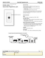
LUTRON<br />
LIGHTING<br />
SYSTEM<br />
HANDHELD<br />
PROGRAMMER<br />
PORT<br />
Lighting Programmer<br />
Intensity Fade Fade Delay Zone Finder<br />
LUTRON®<br />
SCENES ZONES AREAS<br />
Scene<br />
Zone<br />
(Area)<br />
HELP &<br />
SYSTEM<br />
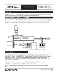
Overview<br />
The GRAFIK 6000 Lighting Control System provides centralized preset<br />
lighting control for commercial facilities and large residences. The system<br />
consists of touch-button Wallstations and handheld wireless remote<br />
controls located throughout a building, plus a central control panel and<br />
one or more dimming panels located in an electrical closet. System<br />
design, setup, and monitoring are accomplished via menu-driven<br />
personal computer software, provided with each system.<br />
System Features<br />
<br />
<br />
<br />
<br />
<br />
<br />
Total centralized control<br />
PC user interface<br />
Windows ® -based setup software<br />
Disk save and download capability<br />
Built-in timeclock, partitioning and sequencing<br />
Zone-adjustable fade times and delay times<br />
System Maximums<br />
<br />
<br />
<br />
<br />
<br />
<br />
<br />
32 local areas<br />
4 master or global areas<br />
512 zones<br />
544 scenes<br />
96 control points (3 links of 32 each)<br />
32 dimming panels<br />
768 circuits<br />
System setup &<br />
monitoring via PC<br />
(located in clean environment)<br />
Analog phone<br />
line for modem<br />
LIGHTING LOADS<br />
located throughout building<br />
Incandescent/<br />
Tungsten<br />
Electronic<br />
or Magnetic<br />
Low-Voltage<br />
Neon/Cold<br />
Cathode<br />
Switched<br />
Load<br />
T-12, T-8, T-5 plus T-4<br />
Compact Fluorescent<br />
CENTRALIZED CONTROL<br />
located in electrical closet<br />
Power IN<br />
GRAFIK 6000<br />
Processor Panel<br />
GRAFIK Eye<br />
Dimming Panel<br />
To additional<br />
dimming panels as<br />
required<br />
GRAFIK 6000 CONTROLS<br />
located throughout building<br />
From additional controls as required -<br />
96 max. (3 links of 32 each) per system<br />
2-Button<br />
Door Jamb<br />
7-Button<br />
Door Jamb<br />
2-Button<br />
Wall<br />
4-Button<br />
Wall<br />
5-Button<br />
Wall<br />
5-Button<br />
Wall<br />
Raise/Lower<br />
5-Button<br />
Wall<br />
Receiver<br />
Ceiling<br />
Receiver<br />
AV<br />
Interface<br />
Handheld<br />
Programmer<br />
Jack<br />
Viseo<br />
Class 2/PELV System Wiring - 4-wire daisy chain link<br />
Length of Link<br />
500' (152m)<br />
2000' (610m)<br />
Power<br />
2-#18 AWG (1.0 mm 2 )<br />
2- #12 AWG (2.5 mm 2 )<br />
Data<br />
(others available)<br />
Contact <strong>Lutron</strong><br />
1 twisted, shielded pair<br />
<strong>Lutron</strong> P/N GRX-CBL-46L<br />
(Belden No. 9461or Alpha<br />
No. 2211)<br />
Handheld Remotes<br />
I/O from contactclosure<br />
building<br />
devices, security<br />
systems, AV<br />
equipment, etc.<br />
Handheld<br />
Programmer
Table of Contents<br />
Step-by-Step Instructions<br />
Page<br />
Install System<br />
STEP 1: Mount Wallboxes ..........................................................2-3<br />
STEP 2: Mount Panels ................................................................4-8<br />
STEP 3: Install Electronics in Enclosure ........................................9<br />
STEP 4: Wire System ..............................................................10-14<br />
STEP 5: Set Address DIP Switches ........................................15-16<br />
STEP 6: Install Controls and Walljacks ........................................17<br />
Page<br />
Start Up System<br />
STEP 7: Activate Loads in Bypass ............................................17<br />
STEP 8: Activate Controls ..........................................................18<br />
Set Up System<br />
STEP 9: Set Normal/Emergency Switch......................................19<br />
Reference Sheets<br />
Page<br />
User-Supplied PC Specifications<br />
Hardware and Software Requirements ............................20<br />
Table of Contents for GRAFIK 5000/6000 Lighting Control System
Mount Wallboxes<br />
STEP 1:<br />
Mount Wallboxes<br />
Use wallboxes with a minimum depth of 2-3/4” (70mm). <strong>Lutron</strong><br />
recommends 3-1/2” (89mm) deep wallboxes for OMX Series<br />
Wallstations. Multi-gang installations may require spacers between<br />
wallboxes. Mount standard US wallboxes flush to 1/8” (3mm) below<br />
finished wall surface. See instruction sheets shipped with product for<br />
all other boxes. Finished wall should not have gaps around the wallbox<br />
of greater than 1/8” (3mm).<br />
Control<br />
Wallbox<br />
NTOMX-4S<br />
NTOMX-4S-NRL<br />
NTOMX-4B<br />
NTOMX-2B<br />
NTOMX-4S-IR<br />
NTOMX-62J<br />
NTOMX-HHPJ<br />
NTOMX-4S<br />
OMX-7B-DW<br />
OMX-2B-DW<br />
EOMX-4S<br />
EOMX-8S<br />
EOMX-2B<br />
EOMX-4S-IR<br />
EOMX-8S-IR<br />
OMX-4SLB-DW<br />
NTOMX-KP5<br />
NTOMX-KP10<br />
NTOMX-KP15<br />
NTOMX-LB6<br />
NTOMX-LB6-RL<br />
NTOMX-LB9<br />
NTOMX-LB9-RL<br />
SOMX-4S-NL<br />
SOMX-4S-IR-NL<br />
SOMX-2B-NL<br />
Standard US wallbox 2 3/4 in. deep minimum<br />
or<br />
<strong>Lutron</strong> No. 241-519: 3-1/2 in. (89mm) deep (1 per gang)<br />
<strong>Lutron</strong> No. 241-399 (provided). Refer to instructions<br />
packaged with controls<br />
OMX-AV<br />
MX-RPTR<br />
OMX-CIR<br />
MX-RS232<br />
LUT-DMX<br />
OMX-RACP<br />
1900 box (4 in. x 4 in. box) or <strong>Lutron</strong> No. 241-496<br />
Mounts in ceiling with special mounting ring (provided)<br />
OMX-DACPI<br />
Standard US wallbox, 4 gang, 2 3/4 in. deep minimum, 3-1/2 in. deep<br />
recommended<br />
or<br />
<strong>Lutron</strong> No. 241-519: 3-1/2 in. (89mm) deep, (1 per gang, 4 required)<br />
All other Controls<br />
Consult <strong>Lutron</strong><br />
<br />
For<br />
More Information...<br />
See instructions packaged with each control.<br />
2 Step by Step Instructions for GRAFIK 5000/6000 Lighting Control System
Mount Wallboxes<br />
STEP 1:<br />
Mount Wallboxes (cont.)<br />
Mount OMX-7B-DW, OMX-4SLB-DW, and OMX-2B DW<br />
Architrave Style Controls with or without wallbox (proper size<br />
wallbox available only through <strong>Lutron</strong> - P/N 241-399). Wood<br />
screws are provided for mounting control without a wallbox.<br />
Notes:<br />
The back of the control's yoke must be flush with the surface of<br />
the wall so that the faceplate will mount properly (see diagram<br />
directly to right).<br />
The screws must be driven into a material that supports them.<br />
<strong>Lutron</strong> recommends framing the location in wood.<br />
OMX-7B-DW, OMX-4SLB-DW, and OMX-2B-DW Mounting<br />
(side view, without wallbox)<br />
3-1/2 in. (90mm) recommended<br />
wall<br />
stud<br />
1 2 3 4 5 6<br />
1 2 3 4<br />
yoke<br />
Back View<br />
OMX-7B DW, OMX-4SLB-DW, and OMX-2B-DW Mounting<br />
(with wallbox)<br />
OMX-7B-DW, OMX-4SLB-DW, and OMX-2B-DW Mounting<br />
(without wallbox)<br />
<strong>Lutron</strong> P/N 241-399<br />
<strong>Lutron</strong> No.<br />
241-399<br />
yoke<br />
yoke<br />
Door Trim<br />
90 mm<br />
3-1/2”<br />
32 mm<br />
1-1/4”<br />
Step by Step Instructions for GRAFIK 5000/6000 Lighting Control System<br />
3
Mount Panels<br />
STEP 2:<br />
Mount Panels<br />
GP-3, 4<br />
(Dimensions and Conduit Entry)<br />
130 mm<br />
(5 1/8”)<br />
Top View<br />
92 mm<br />
(3 5/8”)<br />
160 mm<br />
(6 1/4”)<br />
29 mm<br />
(1 1/8”)<br />
SUGGESTED CONTROL WIRING ENTRY<br />
Left Side<br />
Front View<br />
244 mm<br />
(9 5/8”)<br />
Right Side<br />
130 mm<br />
(5 1/8”)<br />
30 mm (1 3/16”)<br />
495 mm<br />
(19 1/2”)<br />
457 mm<br />
(18”)<br />
537 mm<br />
(21 1/8”)<br />
29 mm (1 1/8”) 29 mm (1 1/8”)<br />
70 mm<br />
(2 3/4”)<br />
279 mm<br />
(11”)<br />
Bottom View<br />
70 mm<br />
(2 3/4”)<br />
SUGGESTED LOAD WIRING ENTRY<br />
SUGGESTED FEED WIRING ENTRY<br />
KEYHOLE ACCEPTS A MAXIMUM<br />
OF 1/4" (6.5mm) MOUNTING BOLT.<br />
(No. 10 RECOMMENDED)<br />
SINGLE KNOCKOUTS ARE 7/8"<br />
(23mm) DIA. DUALKNOCKOUTS<br />
ARE 7/8" (23mm) DIA. AND 1 1/8"<br />
(29mm) DIA.<br />
70 mm<br />
(2 3/4”)<br />
38 mm<br />
(1 1/2”)<br />
140 mm<br />
(5 1/2”)<br />
38 mm<br />
(1 1/2”)<br />
Caution! This equipment is aircooled.<br />
Vents must not be<br />
blocked or you will void the<br />
warranty.<br />
<br />
For<br />
More Information...<br />
See GP 3,4 Installation <strong>Guide</strong> provided with the panel .<br />
4<br />
Step by Step Instructions for GRAFIK 5000/6000 Lighting Control System
Mount Panels<br />
STEP 2:<br />
Mount Panels (cont.)<br />
GP8, 12, 16, 20, or 24<br />
(Dimensions and Conduit Entry)<br />
Top View<br />
711 mm<br />
(28”)<br />
Left Side<br />
Suggested feed<br />
wiring entry<br />
102 mm<br />
(4”)<br />
51 mm<br />
(2”) 51 mm<br />
Front View<br />
(2”)<br />
Suggested load<br />
wiring entry<br />
Removable top cover is shipped in the same<br />
box as the panel.<br />
Right Side<br />
889 mm<br />
(35”)<br />
838 mm<br />
(33”)<br />
330 mm<br />
(13”)<br />
Keyhole accepts a maximum of 5/16" (8 mm)<br />
mounting bolt (1/4" (m8) recommended).<br />
Class 2/PELV entry knockout is 7/8" dia. (22 mm)<br />
304 mm<br />
(12”)<br />
Bottom View<br />
51 mm<br />
(2”)<br />
Required control<br />
wiring entry<br />
304 mm<br />
(12”)<br />
Caution! This equipment is air-cooled. Vents must not be<br />
blocked or you will void the warranty.<br />
Note: GP-8 through 24 must have its top cover punched for Feed and<br />
Load Circuit wiring.<br />
<br />
For<br />
More Information...<br />
See GP Installation <strong>Guide</strong> provided with the panel<br />
Step by Step Instructions for GRAFIK 5000/6000 Lighting Control System<br />
5
Mount Panels<br />
Step 2: Mount Panels (cont.)<br />
GRAFIK 6000 Processor Panel<br />
Dimensions and Conduit Entry<br />
Dedicated 15A or 20A (120VAC) or 10A @ 220-240VAC<br />
circuit enters here<br />
45 mm<br />
(1 3/4”)<br />
25 mm<br />
(1”)<br />
13 mm (1/2”) and 19 mm (3/4”)<br />
conduit knockouts (18)<br />
365 mm (14 3/8”)<br />
51 mm (2”)<br />
25 mm (1”)<br />
98 mm<br />
(3 7/8”)<br />
Cover<br />
MOUNT THIS END UP<br />
883 mm<br />
(34 3/4”)<br />
Mounting holes for surface<br />
mounting. Do not use any other<br />
holes for mounting.<br />
Mounting holes (4) for flush<br />
mounting<br />
13 mm (1/2”). conduit knockouts<br />
RS232 input enters here<br />
25 mm (1”)<br />
51 mm (2”)<br />
MXINP-ENC<br />
Dimmer panel link enters here<br />
Wallstation links enter here<br />
User interface link<br />
6 Step by Step Instructions for GRAFIK 5000/6000 Lighting Control System
Mount Panels<br />
STEP 2:<br />
Mount Panels (cont.)<br />
GP-3, 4<br />
(Suggested Mounting)<br />
CEILING<br />
GP-8 through 24<br />
(Suggested Mounting)<br />
CEILING<br />
WIRING RACEWAY<br />
CLASS 2 (PELV)<br />
WIRING TO<br />
CONTROLS<br />
12" (305mm)<br />
MINIMUM<br />
CLEARANCE TO ANY<br />
OBSTRUCTION<br />
FEED<br />
WIRING<br />
LOAD<br />
CIRCUIT<br />
WIRING<br />
12" (305mm)<br />
MIN.<br />
AIR FLOW<br />
CLASS 2 (PELV)<br />
WIRING TO<br />
CONTROLS<br />
LOAD<br />
CIRCUIT<br />
WIRING<br />
FEED WIRING<br />
12" (305mm) MIN.<br />
WIRING RACEWAY<br />
12" (305mm)<br />
MINIMUM<br />
CLEARANCE TO ANY<br />
OBSTRUCTION<br />
AIR<br />
FLOW<br />
WALL<br />
WALL<br />
Front View Side View Front View Side View<br />
Notes:<br />
■<br />
■<br />
■<br />
■<br />
■<br />
■<br />
Panel generates heat. Mount only where ambient temperature will be<br />
0°C-40°C (32 °F-104 °F).<br />
Reinforce wall structure as required for weight and local codes.<br />
Panel clearances are 12" (305 mm) above and below and 0" to each<br />
side. (allow room for Class 2/PELV clearance).<br />
Indoor Use Only. NEMA, Type 1 enclosure, IP2O.<br />
Relative Humidity < 90% non-condensing.<br />
GP Panels must be mounted within 7° of true vertical.<br />
Panel<br />
GP3,4<br />
GP8<br />
GP12<br />
GP16<br />
GP20<br />
GP24<br />
Max BTUs/Hr.<br />
685<br />
1365<br />
2045<br />
2725<br />
3405<br />
4085<br />
Weight w/o Packaging<br />
30 lbs (14kg)<br />
115 lbs (52kg)<br />
130 lbs (59kg)<br />
145 lbs (66kg)<br />
160 lbs (73kg)<br />
175 lbs (80kg)<br />
Warning! CE marked panels with 10A circuit breakers are<br />
intended for industrial or commercial installations.<br />
Caution! Dimming Panels will hum slightly and internal<br />
relays will click while in operation. Mount where audible<br />
noise is acceptable.<br />
Caution! Mount panel so line (mains) voltage wiring will<br />
be at least 6 feet (1.8 m) from sound or electronic<br />
equipment and its wiring.<br />
Warning! CE marked panels with 10A circuit breakers are<br />
intended for industrial or commercial installations.<br />
Caution! This equipment is air-cooled. Vents must not be<br />
blocked or you will void the warranty.<br />
Step by Step Instructions for GRAFIK 5000/6000 Lighting Control System<br />
7
Mount Panels<br />
STEP 2:<br />
Mount Panels (cont.)<br />
GRAFIK 6000 Processor Panel Flush Mount<br />
(Suggested Mounting)<br />
CEILING<br />
GRAFIK 6000 Processor Panel Surface Mount<br />
(Suggested Mounting)<br />
CEILING<br />
DEDICATED<br />
15/20 AMP CIRCUIT<br />
DEDICATED<br />
15/20 AMP CIRCUIT<br />
CLASS 2<br />
(PELV)<br />
WIRING TO<br />
CONTROLS<br />
WALL SHOWN CUT AWAY FOR<br />
CLARITY<br />
STUDS MOUNTED 16" (407mm)<br />
ON CENTER<br />
WALL<br />
CLASS 2 (PELV)<br />
WIRING TO<br />
CONTROLS<br />
THIS SURFACE MUST BE SPACED<br />
1/8" (32mm) OFF OF MOUNTING<br />
SURFACE TO ALLOW SUBPLATE TO<br />
PROTRUDE<br />
WALL<br />
Front View Side View Front View Side View<br />
Notes:<br />
<br />
<br />
<br />
<br />
<br />
Indoor Use Only. Type 1 enclosure.<br />
Relative Humidity < 90% non-condensing.<br />
Must be mounted as shown.<br />
No clearance required above, below, or to each side.<br />
Weight: 45lbs (20kg) with electronics.<br />
Caution! Mount panel so that back surface is 1/8 in.<br />
(32mm) away from any wall surface. Subplate mounting<br />
screws must protrude 1/8 in. (32mm) behind panel.<br />
Caution! Only use the four holes indicated when<br />
surface mounting. Other holes in the back of panel are<br />
used for mounting the subplate.<br />
8 Step by Step Instructions for GRAFIK 5000/6000 Lighting Control System
DIMMER PANEL<br />
LINK<br />
USER<br />
INTERFACE<br />
CONTROL<br />
LINK #_____<br />
CONTROL<br />
LINK #_____<br />
CONTROL<br />
LINK #_____<br />
Install Electronics<br />
in Enclosure<br />
STEP 3: Install Electronics in Enclosure<br />
GRAFIK 6000 Processor Panel<br />
Subplate Installation<br />
Dedicated feed (see below)<br />
See Detail A on Page 14 for wiring<br />
N<br />
H<br />
UNSWITCHED<br />
Note: Receptacle present only for<br />
120VAC version<br />
UP<br />
GRAFIK 6000 Panel Power Switch<br />
SYSTEM POWER<br />
Use screws shipped with<br />
enclosure (4) to secure<br />
electronics<br />
GRAFIK 6000 Main Board<br />
GRAFIK 6000 Subplate (see model<br />
numbers below)<br />
Wiring terminal blocks (see Detail<br />
B on Page 14<br />
RS232 interface (to AV equipment<br />
provided by others)<br />
1 2 3 4 5 1 2 3 4 5 1 2 3 4 5 1 2 3 4 5 1 2 3 4 5<br />
MXIMP-ENC<br />
MODEL NUMBER<br />
GR6MXINP<br />
GR6MXINP-220/240<br />
DEDICATED FEED<br />
120VAC, 15A/20A<br />
220-240VAC, 10A<br />
Step by Step Instructions for GRAFIK 5000/6000 Lighting Control System<br />
9
Wire System<br />
STEP 4: Wire System (Control Wiring - Class 2/PELV)<br />
#12 AWG Power (red), terminal 2 to 2<br />
Note: Contact <strong>Lutron</strong> for other wire sizes<br />
#18 AWG Sense (orange), terminal 5 to 5<br />
(used only when linking dimming panels)<br />
#12 AWG Common (black), terminal 1 to 1<br />
Note: Contact <strong>Lutron</strong> for other wire sizes<br />
<strong>Lutron</strong> Cable P/N GRX-CBL-46L-500 (Non-Plenum)<br />
(Contact <strong>Lutron</strong> for other available wire types and sizes)<br />
#22 AWG MUX (white), twisted,<br />
shielded pair from terminal 3 to 3<br />
#22 AWG MUX (purple), twisted,<br />
shielded pair from terminal 4 to 4<br />
#24 AWG Drain, terminal<br />
D to D (if applicable)<br />
twisted, shielded<br />
pair from<br />
Belden (#9461) or<br />
Alpha (#2211)<br />
also<br />
recommended<br />
To additional panels. A<br />
<strong>Lutron</strong> LT1 (Link Terminator)<br />
must be used to terminate<br />
link at the last panel.<br />
G6000 Processor Panel<br />
GP Panel<br />
GP Panel<br />
See page 14 for more<br />
wiring detail on this<br />
processor panel.<br />
LT-1<br />
LT-1<br />
Dimmer Panel<br />
Link<br />
Circuit Selector in the GP Panel<br />
#12 AWG<br />
(2.5 mm 2 )<br />
#22 AWG<br />
(1.0 mm 2 )<br />
Wallstation<br />
Link C<br />
Wallstation<br />
Link B<br />
RS-232<br />
Interface<br />
Wallstation Link A<br />
Drain/Shield<br />
To User Interface/PC Link -<br />
NTOMX-62J (see page 12 for<br />
more details)<br />
#18 AWG<br />
(1.0 mm 2 )<br />
1 2 3 4 D 5<br />
C<br />
D<br />
#18 AWG<br />
(1.0 mm 2 )<br />
To DMX-512 stageboard or panels<br />
where Link B controls circuits. A<br />
<strong>Lutron</strong> LT1 (Link Terminator)must<br />
be used to terminate Link B at the<br />
last panel (LT1 not necessary for<br />
stageboard-already built in).<br />
Data A OK<br />
Power<br />
Data B OK<br />
Common<br />
24VFW<br />
MUX<br />
MUX<br />
Drain<br />
Sense<br />
1 2 3 4 D 5<br />
A Link<br />
Link<br />
B<br />
Comm<br />
C<br />
MUX<br />
MUX<br />
Drain<br />
D<br />
Common<br />
24VFW<br />
1 2 3 4 D 5<br />
MUX<br />
MUX<br />
Sense<br />
Link A Terminals<br />
Drain/Shield<br />
10 Step by Step Instructions for GRAFIK 5000/6000 Lighting Control System
Wire System<br />
STEP 4:<br />
Wire System (Control Wiring - Class 2/PELV) (cont.)<br />
<strong>Lutron</strong> Cable P/N GRX-CBL-46L-500 (Non-Plenum)<br />
Note: Total length of wire for any link may be no more than<br />
2000 ft. for #12 AWG (610m for 2.5 mm 2 ).<br />
Back of Wallstation<br />
4<br />
3<br />
2<br />
1<br />
To additional Control Units, Wallstations,<br />
Panels, or Control Interfaces. A <strong>Lutron</strong> LT1<br />
(Link Terminator) must be used to<br />
terminate link.<br />
Wallstation Link A from<br />
GRAFIK 6000 Processor Panel<br />
Drain/Shield–<br />
Keep short and isolated<br />
2 #12 AWG (2.5 mm 2 )<br />
4<br />
3<br />
2<br />
1<br />
1 #18 AWG (1.0 mm 2 )<br />
2 #12 AWG (2.5 mm 2 )<br />
Wallstation<br />
1 #18 AWG (1.0 mm 2 )<br />
Notes:<br />
■<br />
■<br />
■<br />
All control wiring is Class 2/PELV. Do not place any of these<br />
wires in with line voltage (mains voltage) wiring.<br />
GRAFIK 6000 Processor Panel and GRAFIK Eye Dimming Panels<br />
can be in the middle of the wiring or on the end as shown.<br />
2 #12 AWG (2.5mm 2 ) wires will not fit in the Wallstation Control<br />
terminal blocks. Use the diagram shown to make the<br />
connections in the wallbox. #12 AWG (2.5mm 2 ) is necessary due<br />
to voltage drop on the wire.<br />
■<br />
■<br />
■<br />
Connect the Drain/Shield to terminal ‘D’, if this terminal is<br />
available. The Drain is a bare wire – care must be taken so that it<br />
does not touch ground (earth) or wallstation circuitry.<br />
Make wire connections inside the wallbox and GP panel or in a<br />
junction box (provided by others) within 8 ft. (2.4 m) of the<br />
terminals. Do not use "T" taps in excess of 8 ft. (2.4 m).<br />
Use the wire connector required by local code (those shown are<br />
common in the USA).<br />
Step by Step Instructions for GRAFIK 5000/6000 Lighting Control System<br />
11
Lighting System Computer Interface<br />
Coopersburg, PA 18036<br />
Model: PJ62-ADPT<br />
Lighting System<br />
Computer<br />
RS-485 - Isolated<br />
Serial Port<br />
50 ft. max to wall jack<br />
RS232 25 ft. max<br />
LUTRON<br />
LIGHTING<br />
SYSTEM<br />
COMPUTER<br />
PORT<br />
Lighting Programmer<br />
LUTRON®<br />
Scene<br />
Zone<br />
(Area)<br />
Intensity Fade Fade Delay Zone Finder<br />
LUTRON<br />
LIGHTING<br />
SYSTEM<br />
COMPUTER<br />
PORT<br />
LUTRON<br />
LIGHTING<br />
SYSTEM<br />
HANDHELD<br />
PROGRAMMER<br />
PORT<br />
LUTRON<br />
LIGHTING<br />
SYSTEM<br />
HANDHELD<br />
PROGRAMMER<br />
PORT<br />
Wire System<br />
STEP 4:<br />
Wire System (cont.)<br />
Wiring Overview<br />
LT-1<br />
LINE IN<br />
OUT TO LOADS LINE IN OUT TO LOADS<br />
GP 3 AND 4 GP 8-24 GP 8-24<br />
GR6MXINP<br />
OR<br />
GR6MXINP-220/240<br />
120V 15A/20A OR<br />
220-240V 10A<br />
DEDICATED CIRCUIT<br />
OUT TO LOADS<br />
LINE IN<br />
LT-1 LT-1 LT-1<br />
3 #18AWG (1mm 2 ) AND<br />
1 TSP<br />
RS-232<br />
User-supplied standard analog phone line for<br />
modem<br />
DIMMER PANEL LINK<br />
Wallstation Link C<br />
NTOMX-62J<br />
NTOMX-62J<br />
LUTRON<br />
PJ62-ADPT-1<br />
ADPT READY<br />
RX DATA<br />
TX DATA<br />
TX ENABLE<br />
User interface link<br />
NTOMX-HHJP<br />
NTOMX-2B<br />
2 #12AWG (2.5 mm 2 ) and 1 TSP<br />
#22AWG (1.0mm 2 ) (twisted,<br />
shielded pair)<br />
Personal computer (see Page 20 for<br />
PC specifications)<br />
9-pin male to parallel port (<strong>Lutron</strong>-supplied)<br />
NTOMX-2B<br />
NTOMX-2B<br />
LOCATE COMPUTER, PJ62-ADPT-1, AND NTOMX-62J IN A CLEAN ENVIRONMENT<br />
Notes:<br />
• Do not home run individual controls. <strong>Lutron</strong> requires<br />
daisy-chain wiring.<br />
2 #12AWG (2.5 mm 2 ) and 1 TSP<br />
#22AWG (1.0mm 2 ) (twisted,<br />
shielded pair)<br />
NTOMX-4S<br />
NTOMX-HHJP<br />
• Max 32 controls/link.<br />
GR6-HHP<br />
NTOMX-4B<br />
NTOMX-4B<br />
• Max 96 controls/system.<br />
• LT-1 supplied in GRAFIK 6000 processor panel.<br />
OMX-AV<br />
OMX-CIR<br />
OMX-2B-DW<br />
OMX-7B-DW<br />
LT-1<br />
Wallstation Link A<br />
LT-1<br />
Wallstation Link B<br />
12<br />
Step by Step Instructions for GRAFIK 5000/6000 Lighting Control System
Wire System<br />
STEP 4:<br />
Wire System (cont.)<br />
Feed Wiring (Mains Voltage Wiring)<br />
Panel<br />
GP3 (277 V)<br />
GP3 (120 V, 230 V)<br />
GP4<br />
GP8 through 24 Main Lugs<br />
GP 8 through 24 Main Breaker<br />
Load Circuit Wiring<br />
Panel<br />
GP3, 4<br />
GP8 through 24<br />
Wire Size<br />
1 or 2 #10 AWG - #14 AWG<br />
#6 AWG (10 mm 2 ) - #14 AWG (1.0 mm 2 )<br />
#10 AWG (4 mm 2 ) - #14 AWG (1.0 mm 2 )<br />
#2/0 AWG (50 mm 2 ) - #14 AWG (1.0 mm 2 )<br />
see rating on breaker<br />
Wire Size<br />
#10 AWG (4mm 2 ) - #14 AWG (1.0mm 2 )<br />
#10 AWG (4mm 2 ) - #14 AWG (1.0mm 2 )<br />
Where to Enter Panel<br />
Bottom Right of Panel (Bottom or Side Entry)<br />
Bottom Right of Panel (Bottom or Side Entry<br />
Bottom Right of Panel (Bottom or Side Entry<br />
Top left of Panel (Top entry only)<br />
Top left of Panel (Top entry only)<br />
Where to Enter Panel<br />
Bottom Left of Panel (Bottom or Side Entry)<br />
Top Right of Panel (Top Entry Only)<br />
Load Wiring:<br />
For all load types except Hi-lume ® FDB or Eco-10 fluorescent dimming<br />
ballasts.<br />
Dimmed Hot (DH) must be used for Non-Dim loads.<br />
Load Wiring:<br />
For Hi-lume FDB or Eco-10 Fluorescent Dimming Ballast<br />
Load<br />
Load Terminals<br />
Notes:<br />
■<br />
■<br />
■<br />
■<br />
DH<br />
SHH<br />
Neutral<br />
Dimmable Load<br />
or<br />
Non Dim Load<br />
Load<br />
GP3 Main Breakers can be removed to ease installation of feed wiring.<br />
For 230V and 240V panels, ‘Hot’ is referred to as ‘Live’. Therefore,<br />
terminals will be labeled DL, SL, and L.<br />
Run wiring so that line (mains) voltage wiring will be at least 6 ft.<br />
(1.8 m) from sound or electronic equipment and its wiring.<br />
Hot (H) is used for bypass on all panels. It can also be used as a<br />
protected Hot output on GP3, 8, 12, 16, 20, and 24 (added Hot current<br />
plus Load current must not exceed breaker limits).<br />
Load Terminals<br />
Neutral<br />
DH<br />
SHH<br />
LUTRON®<br />
Eco-10 OR<br />
Hi-lume FDB Ballast<br />
Fluorescent Lamp<br />
Caution! Verify with electronic low voltage transformer or<br />
ballast manufacturer that product can be controlled with a<br />
phase control dimmer before bypass jumpers are removed.<br />
Caution! Switched Hot (SH) must only be used for Hilume<br />
FDB or Eco-10 loads. Use the Dimmed Hot (DH) for<br />
all Non-Dim Load Types.<br />
Danger! Feed-through panels, such as GP4, may be fed by<br />
multiple circuits. Locate and lock each supply breaker in the<br />
off position before wiring feed or loads.<br />
Warning! CE marked panels are appliances. A distribution<br />
panel must provide a main circuit breaker that does not<br />
exceed the rating of the panel.<br />
Step by Step Instructions for GRAFIK 5000/6000 Lighting Control System<br />
13
Wire System<br />
STEP 4: Wire System (cont.)<br />
Wire GRAFIK 6000 Panel<br />
Detail A<br />
Input Feed Wiring<br />
(Line Voltage)<br />
TO DEDICATED CIRCUIT<br />
N<br />
H<br />
GROUND/EARTH<br />
NEUTRAL<br />
HOT/LIVE<br />
Detail B<br />
Wallstation, Dimmer Panel, and<br />
User Interface Link Wiring (Low<br />
Voltage Wiring)<br />
Wire Terminals 1 to 1, 2 to 2, 3 to 3, . . .<br />
STATUS LEDs<br />
1 PER LINK<br />
1 2 3 4 5 1 2 3 4 5 1 2 3 4 5 1 2 3 4 5 1 2 3 4 5 1 2 3 4 5<br />
1<br />
2<br />
3<br />
4<br />
5<br />
1<br />
2<br />
3<br />
4<br />
5<br />
1<br />
2<br />
3<br />
4<br />
5<br />
1<br />
2<br />
3<br />
4<br />
5<br />
1<br />
2<br />
3<br />
4<br />
5<br />
1<br />
2<br />
3<br />
4<br />
5<br />
TO DIMMER<br />
PANEL LINK<br />
TO USER<br />
INTERFACE/<br />
COMPUTER LINK<br />
NOT USED<br />
TO<br />
WALLSTATION<br />
LINK A<br />
TO<br />
WALLSTATION<br />
LINK B<br />
TO<br />
WALLSTATION<br />
LINK C<br />
14<br />
Step by Step Instructions for GRAFIK 5000/6000 Lighting Control System
Set Address DIP Switches<br />
STEP 5:<br />
Link<br />
Set Address DIP Switches<br />
Note: Photocopy 1 page for each link.<br />
1<br />
2<br />
3<br />
4<br />
5<br />
6<br />
7<br />
8<br />
9<br />
10<br />
11<br />
1 2 3 4 5 6 1 2 3 4 5 6 1 2 3 4 5 6<br />
12<br />
23<br />
13<br />
24<br />
14<br />
25<br />
15<br />
26<br />
16<br />
27<br />
17<br />
28<br />
18<br />
29<br />
19<br />
30<br />
20<br />
31<br />
21<br />
32<br />
22<br />
Notes:<br />
<br />
<br />
<br />
Every Wallstation and Control Interface per link must be given a<br />
unique address at the time of installation for the system to work<br />
properly. Set DIP switches to match addresses shown in "User Set Up<br />
Software," "Wallstation Summary by Area" report, or Control Schedule<br />
in <strong>Lutron</strong>-supplied drawings.<br />
OMX-AV has 8 DIP switch positions. Position 8 sets the output<br />
function. Positions 6 and 7 are unused.<br />
NTOMX-62J and NTOMX-HHPJ do not have DIP switches.<br />
UP<br />
(ON)<br />
DOWN<br />
(OFF)<br />
"U" on Wallstation Summary<br />
"D" on Wallstation Summary<br />
Back of Wallstation<br />
Control (typical)<br />
Caution! Do not install controls in wallbox without<br />
setting the DIP Switches and recording them above.<br />
DIP Switch location<br />
4<br />
3<br />
2<br />
1<br />
Note: This diagram shows a common<br />
Wallstation back. Some newer products<br />
may have a different layout. See product<br />
instructions for detailed drawings.<br />
Step by Step Instructions for GRAFIK 5000/6000 Lighting Control System<br />
15
LUTRON<br />
LUTRON<br />
COOPERSBURG, PA 18036<br />
INTERFACE CONTROL<br />
CLASS 2 DEVICE<br />
Set Address DIP Switches<br />
STEP 5:<br />
Set Address DIP Switches (cont.)<br />
Address DIP switches may have been preset when the system was built and<br />
tested at the factory. If this is the case, your control will be labeled with a<br />
listing of the station addresses.<br />
If your controls are not labeled, you need to set the addresses yourself. Refer<br />
to the example at right.<br />
If your system drawings are not clear, or if your controls do not have unique<br />
addresses, contact <strong>Lutron</strong> before installing. This will prevent controls from<br />
having to be removed from the wall to set their addresses.<br />
To GRX-MXINP<br />
Panel<br />
Wallstation Link<br />
NTOMX-2B,<br />
Station A1,<br />
Lobby,Scene 1 &<br />
Off<br />
NTOMX-4S,<br />
Station A2,<br />
Conference Room,<br />
Scene 1 & Off<br />
OMX-AV<br />
OMX-AV, Station A3,<br />
A/V Room, Scenes 5-8<br />
& Off<br />
To A/V equipment (by<br />
others)<br />
Wallstation addresses are shown in the station designation given each<br />
control on the one-line diagrams supplied with the GRAFIK 6000 Lighting<br />
Control System. For example, a wallstation designation of “Station A3” is<br />
connected to Wallstation link “A” and has an address of “3.” Refer to control<br />
instruction sheets for addressing each control.<br />
SAMPLE<br />
Sample Wallstation Summary<br />
X -- Not Used<br />
U -- Up (On)<br />
D -- Down (Off)<br />
WALLSTATION SUMMARY BY AREA - C:\G6000\TEMP.GRX<br />
7 August 1999<br />
Entry Hall<br />
Address Switch Setting<br />
LVI Entry Hall 7B - Architrave 7 Button<br />
Scenes 1 - 4 and OFF Link A Address 1 UUUUUX<br />
LV2 Entry Hall 7B - Architrave 7 Button<br />
Scenes 1 - 4 and OFF Link A Address 2 DUUUUX<br />
LV3 Entry Hall 7B - Architrave 7 Button<br />
Scenes 1 - 4 and OFF Link A Address 3 UDUUUX<br />
Living Room<br />
Address Switch Setting<br />
LV4 Living Room 7V - Architrave 7 Button<br />
Scenes 1 - 4 and OFF Link A Address 4 DDUUUX<br />
LV5 Living Room 7B - Architrave 7 Button<br />
Scenes 1 - 4 and OFF Link A Address 5 UUDUUX<br />
LV29 Entry Hall Multi 7B - Architrave 7 Button<br />
Scenes 1 - 4 and OFF Link A Address 29 UUDDDX<br />
16<br />
Step by Step Instructions for GRAFIK 5000/6000 Lighting Control System
Install Controls and<br />
Activate Loads<br />
STEP 6:<br />
Install Controls and Walljacks<br />
After completing Steps 4 and 5, mount controls. Refer to detailed<br />
mounting instructions packaged with each control.<br />
CONTROL<br />
LINK<br />
CONTROL MOUNTING<br />
SCREWS<br />
ADAPTER MOUNTING<br />
SCREWS<br />
WALLBOX<br />
WALLSTATION<br />
FACEPLATE ADAPTER<br />
FACEPLATE<br />
STEP 7:<br />
Activate Loads in Bypass<br />
A. Complete load wiring.<br />
B. Check that the bypass jumpers are in place. These jumpers<br />
protect the dimmers from faults and must be used to check load<br />
wiring when it is installed or modified.<br />
FEED WIRING<br />
LOAD CIRCUIT WIRING<br />
Warning! For GP-3 or GP-4, the input breaker of circuit 1 is<br />
the control breaker. Control wiring will be powered when this<br />
breaker is turned on.<br />
C. Turn circuit breaker 1 ON.<br />
The load should energize, the breaker should not trip, and total load<br />
current must be less than 16 Amps (10Amps for 220-240V) or 80%<br />
of the Circuit Breaker rating (whichever is less).<br />
D. Repeat 'C.' for each circuit with completed load wiring.<br />
E. Make sure each breaker turns the proper load on and off. Refer to<br />
"User Set Up Software," "Dimmer Panel Load Report," or <strong>Lutron</strong> Load<br />
Schedule. Correct any problems before proceeding.<br />
F. Wire and check all loads connected to system prior to factory<br />
commissioning.<br />
AC RMS CURRENT<br />
TERMINAL BLOCKS<br />
CIRCUIT BREAKERS<br />
Warning! DO NOT remove bypass jumpers at this time.<br />
Bypass Jumpers<br />
Step by Step Instructions for GRAFIK 5000/6000 Lighting Control System<br />
17
1 2 3 4 5 1 2 3 4 5 1 2 3 4 5 1 2 3 4 5 1 2 3 4 5<br />
DIMMER PANEL<br />
LINK<br />
USER INTERFACE<br />
CONTROL<br />
LINK #_____<br />
CONTROL<br />
LINK #_____<br />
CONTROL<br />
LINK #_____<br />
L1<br />
L2<br />
L3<br />
L4<br />
L5<br />
L6<br />
L7<br />
L8<br />
N<br />
H<br />
UNSWITCHED<br />
SYSTEM POWER<br />
L8<br />
L7<br />
L6<br />
L5<br />
L4<br />
L3<br />
L2<br />
L1<br />
Activate Controls<br />
STEP 8:<br />
Activate Controls and GRAFIK 6000 Processor Panel<br />
A. Once all controls are installed and wiring is verified, turn GRAFIK 6000<br />
Processor Panel Power switch ON.<br />
B. The green LEDs in the GRAFIK 6000 Processor Panel should light above<br />
wallstation link A, B, and C. If not, look for a miswire of wires 1 and 2 on<br />
Wallstation link wiring.<br />
C. The GRAFIK 6000 Main Board will begin a 10 second start-up sequence.<br />
The LEDs indicated in the drawing below, should be flashing.<br />
D. The Dimming Panel Data OK LED will flash in the lower left corner of the<br />
GRAFIK 6000 Main Board. The Data OK LED will also flash in each<br />
GRAFIK Eye Dimming Panel with control breakers on. If the Data OK LEDs<br />
are not flashing, look for miswires of wires 3 and 4 on the Dimming Panel<br />
Link.<br />
E. Press a button on each control. The corresponding LED should<br />
light. It may then go out. If the station is flashing all LEDs in<br />
unison, the communication between theGRAFIK 6000 Processor<br />
Panel and the control is miswired. Verify that terminals 1, 3, and 4<br />
are correctly wired.<br />
F. If two or more Wallstations are flashing, at least two wall stations<br />
have duplicate addresses. Correct addresses and repeat the<br />
procedure above.<br />
G. If all wallstations on a link are flashing, check that terminals 1, 3,<br />
and 4 are wired correctly. Make sure that the four green LEDs on<br />
the I/O card are on or flashing rapidly.<br />
(C) LEDs L2 and L3 should be<br />
blinking<br />
(A)<br />
(G) Four green LEDs on I/O<br />
card<br />
I/O Card<br />
(D) Dimming Panel Data OK LED<br />
GRAFIK 6000 Main Board<br />
(B)<br />
18<br />
Step by Step Instructions for GRAFIK 5000/6000 Lighting Control System
Set Normal/Emergency<br />
Switch<br />
STEP 17:<br />
Set Normal/Emergency Switch (Non-<br />
Essential/Essential)<br />
Note: This step is only performed if there are any panels with<br />
Emergency (Essential) Lighting Circuits on the job.<br />
Panels are shipped with Switch 6 (located at the base of each Circuit<br />
Selector) in the center position for operation without any Emergency<br />
(Essential) Lighting Circuits.<br />
Identify a panel supplied with Normal (Non-Essential) power. Move<br />
its Switch 6 to the left position.<br />
For all the Emergency (Essential) Lighting Panels, move Switch 6 to<br />
the right position.<br />
In this arrangement, the Emergency (Essential) Lighting Panel will<br />
“sense” the Normal (Non-Essential) Panel’s power. When Normal<br />
(Non-Essential) power is removed, the Emergency (Essential)<br />
Lighting will go to ‘ord’ override levels (factory set to 100%).<br />
Loss of Normal (Non-Essential) power can be simulated by turning<br />
off all connected Normal (Non-Essential) Panel’s Control Breakers.<br />
When Switch 6 is in its center position (as shipped), terminal 5 has<br />
no affect on the Circuit Selector operation.<br />
Notes:<br />
■ If there is no Normal Panel, a PS-CIP can be used to create an<br />
external ‘sense’ line. See <strong>Lutron</strong>.<br />
■ Override (‘ord’) Level is factory set to full output (100). If less<br />
than full output is needed, contact <strong>Lutron</strong>.<br />
Circuit Selector in Normal<br />
(Non-Essential) Panel<br />
1 2 3 4 D 5 C D<br />
Common<br />
24VFW<br />
MUX<br />
Data A OK<br />
MUX<br />
Drain<br />
Sense<br />
Circuit<br />
Power<br />
Link Link<br />
A B<br />
Comm<br />
MUX<br />
1<br />
2<br />
Data B OK<br />
1 2 3 4 D 5 C D<br />
SELECT CIRCUIT<br />
VIEW VALUE<br />
SELECT VALUE<br />
Link A<br />
3<br />
Link B<br />
4<br />
Value<br />
SELECT VALUE DISPLAYED<br />
Circuit Level<br />
5<br />
Load Type (See Instructions)<br />
Zone Assignment w/ Circuit Schedule<br />
Zone Assignment w/ Zone CaptureTM<br />
Low-End Trim<br />
High-End Trim<br />
Address('Ad' Displayed)<br />
Warning - Read instructions before setting the<br />
Load Type. Instructions show more load types.<br />
Load Type Quick Reference:<br />
--- Unassigned<br />
3-1 Neon / CC<br />
1-1 Incandescent<br />
4-1 Non-Dim<br />
2-1 Fluorescent <strong>Lutron</strong> Hi-lume FDB Ballast<br />
2-2 Fluorescent <strong>Lutron</strong> Tu-Wire TM Ballast<br />
MUX<br />
Drain<br />
Circuit Selector in<br />
Emergency (Essential)<br />
Lighting Panel<br />
1 2 3 4 D 5 C D<br />
Common<br />
24VFW<br />
MUX<br />
Data A OK<br />
MUX<br />
Drain<br />
Sense<br />
Circuit<br />
Power<br />
Link Link<br />
A B<br />
Comm<br />
MUX<br />
1<br />
2<br />
Data B OK<br />
1 2 3 4 D 5 C D<br />
SELECT CIRCUIT<br />
VIEW VALUE<br />
SELECT VALUE<br />
Link A<br />
3<br />
Link B<br />
4<br />
Value<br />
SELECT VALUE DISPLAYED<br />
Circuit Level<br />
5<br />
Load Type (See Instructions)<br />
Zone Assignment w/ Circuit Schedule<br />
Zone Assignment w/ Zone CaptureTM<br />
Low-End Trim<br />
High-End Trim<br />
Address('Ad' Displayed)<br />
Warning - Read instructions before setting the<br />
Load Type. Instructions show more load types.<br />
Load Type Quick Reference:<br />
--- Unassigned<br />
3-1 Neon / CC<br />
1-1 Incandescent<br />
4-1 Non-Dim<br />
2-1 Fluorescent <strong>Lutron</strong> Hi-lume FDB Ballast<br />
2-2 Fluorescent <strong>Lutron</strong> Tu-Wire TM Ballast<br />
MUX<br />
Drain<br />
SW6<br />
SW6<br />
Move left<br />
Move right<br />
Step by Step Instructions for GRAFIK 5000/6000 Lighting Control System<br />
19
User-Supplied PC<br />
Specifications<br />
Reference Sheet<br />
Software Requirements:<br />
• IBM ® compatible PC<br />
• Windows ® 95<br />
• Norton-Lambert Close-Up ® 6.0 (Complete Package, Host and Remote)<br />
Hardware Requirements:<br />
Hardware<br />
CPU<br />
Memory<br />
Display<br />
Disk Space<br />
Available Disk<br />
Floppy Drive<br />
Modem*<br />
Pointing Device<br />
Serial Port**<br />
Minimum Required<br />
Pentium II ® 233 MHz<br />
16 MB RAM<br />
VGA or DSTN<br />
200MB<br />
100MB<br />
3.5" 1.44MB<br />
28.8K BAUD<br />
Mouse or Trackball<br />
High speed (16C550UART)<br />
<strong>Lutron</strong> Recommends<br />
Pentium II ® 350 MHz<br />
32MB RAM<br />
Color VGA or Color DSTN<br />
400MB<br />
200MB<br />
3.5" 1.44MB<br />
33.6K BAUD Internal<br />
PS/2-Style Pointing Device<br />
High speed (16C550UART)<br />
Notes:<br />
* For GRAFIK 6000 use, the modem, serial port, and pointing device must be able to run simultaneously (using unique COM ports and IRQs).<br />
** Serial port is dedicated to the GRAFIK 6000 Lighting System<br />
Disclaimer:<br />
If the customer supplies the PC, then the customer assumes responsibility for selecting a computer that meets the above specifications and agrees to<br />
pay for additional field service days/visits for any problems associated with the PC provided, such as incompatible equipment or other problems that<br />
may require additional time to solve.<br />
The PC should be set up prior to the Field Service Job Start-Up (Commissioning) by the end user of the PC. It should be located in a finished area<br />
that is within 10 feet (3m) of a <strong>Lutron</strong> Computer Port (NTOMX-62J) that is correctly wired to the G6000 Panel. The above software package (Norton-<br />
Lambert's Closeup ® Version 6.0) should be installed, in addition to the modem, in the PC. The end user should setup and configure the modem. The<br />
Closeup Software should be installed with the modem connected and powered. This will generate a report file called: CREPORT.DOC. Send a copy of<br />
this file to the Field Service Department at <strong>Lutron</strong> along with the Pre-Systems Startup Checklist so that the Field Service trip may be arranged.<br />
IBM is a registered trademark of International Business Machines Corporation. Windows is a registered trademark of Microsoft Corporation . Close-Up is a registered<br />
trademark of Norton-Lambert Corporation. Pentium is a registered trademark of Intel Corporation.<br />
20<br />
Reference Sheet for GRAFIK 5000/6000 Lighting Control System
®<br />
Internet: www.lutron.com<br />
E-mail: product@lutron.com<br />
WORLD HEADQUARTERS<br />
<strong>Lutron</strong> Electronics Co. Inc.,<br />
TOLL FREE: (800) 523-9466<br />
(U.S.A., Canada, Caribbean)<br />
Tel: (610) 282-3800;<br />
International ++1- 610-282-3800<br />
Fax: (610) 282-1243;<br />
International++1-610-282-1243<br />
GREAT BRITAIN<br />
<strong>Lutron</strong> EA Ltd.,<br />
Tel: (171) 702-0657;<br />
International ++44-(0)207-702-0657<br />
Fax: (171) 480-6899;<br />
International ++44-(0)207-480-6899<br />
GERMANY<br />
<strong>Lutron</strong> Electronics GmbH<br />
Tel: (309) 710-4590;<br />
International ++49-30-97-10-4590<br />
Fax: (309) 710-4591;<br />
International ++49-30-97-10-4591<br />
FRANCE<br />
<strong>Lutron</strong> LTC<br />
International ++33-(0)1-44-70-71-86<br />
Int’l Fax: ++33-(0)1-44-70-70-97<br />
ASIAN HEADQUARTERS<br />
<strong>Lutron</strong> Asuka Corporation (Japan)<br />
Tel: (03) 5405-7333;<br />
International ++81-3-5405-7333<br />
Fax: (03) 5405-7496;<br />
International ++81-3-5405-7496<br />
HONG KONG SALES OFFICE<br />
<strong>Lutron</strong> GL (Hong Kong)<br />
Tel: 2104-7733;<br />
International ++852-2104-7733<br />
Fax: 2104-7633;<br />
International ++852-2104-7633<br />
SINGAPORE<br />
<strong>Lutron</strong> GL (Singapore)<br />
Tel: ++65-220-4666<br />
Fax: ++65-220-4333<br />
LIMITED WARRANTY<br />
<strong>Lutron</strong> will, at its option, repair or replace any unit that is defective in materials<br />
or manufacture within one year after purchase. For warranty service, return unit<br />
to place of purchase or mail to <strong>Lutron</strong> at 7200 Suter Rd., Coopersburg, PA<br />
18036-1299, postage pre-paid.<br />
This warranty is in lieu of all other express warranties, and the<br />
implied warranty of merchantability is limited to one year from<br />
purchase. This warranty does not cover the cost of installation,<br />
removal or reinstallation, or damage resulting from misuse, abuse,<br />
or improper or incorrect repair, or damage from improper wiring or<br />
installation. This warranty does not cover incidental or<br />
consequential damages. <strong>Lutron</strong>’s liability on any claim for<br />
damages arising out of or in connection with the manufacture,<br />
sale, installation, delivery, or use of the unit shall never exceed<br />
the purchase price of the unit.<br />
This warranty gives you specific legal rights, and you may also have other<br />
rights which vary from state to state. Some states do not allow limitations on<br />
how long an implied warranty lasts, so the above limitation may not apply to<br />
you. Some states do not allow the exclusion or limitation of incidental or<br />
consequential damages, so the above limitation or exclusion may not apply to<br />
you. This product may be covered by one or more of the following U.S. patents:<br />
4,797,599; 4,803,380; 4,825,075; 4,893,062; 5,030,893; 5,191,265; 5,430,356;<br />
5,463,286; 5,530,322; 5,808,417; DES 308,647; DES 310,349; DES 311,170;<br />
DES 311,371; DES 311,382; DES 311,485; DES 311,678; DES 313,738; DES<br />
335,867; DES 344,264; DES 370,663; DES 378,814 and corresponding foreign<br />
patents. U.S. and foreign patents pending.<br />
<strong>Lutron</strong>, GRAFIK Eye, GRAFIK 6000, and Hi-lume are registered trademarks;<br />
GRAFIK 5000 Hi-Power, Eco-10, LIAISON, Designer, Tu-Wire, and Architrave<br />
are trademarks of <strong>Lutron</strong> Electronics Co., Inc. © 2001 <strong>Lutron</strong> Electronics Co.,<br />
Inc.<br />
Safety standards listed above apply to one or more products in the GRAFIK Eye product line. Consult factory for specific information.<br />
LUTRON-Quality Systems<br />
Registered to ISO 9001<br />
<strong>Lutron</strong> Electronics Co., Inc.<br />
Made and printed in U.S.A.<br />
P/N 032-093 Rev. A 5/01