Automatic capacitor banks with detuned filters - Circutor
Automatic capacitor banks with detuned filters - Circutor
Automatic capacitor banks with detuned filters - Circutor

You also want an ePaper? Increase the reach of your titles
YUMPU automatically turns print PDFs into web optimized ePapers that Google loves.
Power factor correction<br />
and harmonic filtering<br />
R.<br />
5 /6<br />
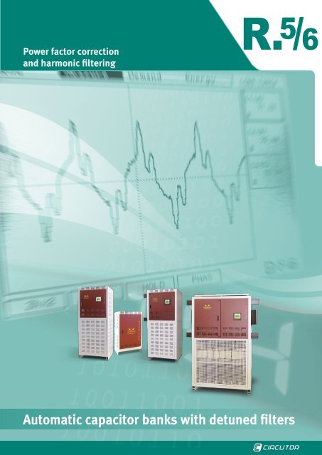
<strong>Automatic</strong> <strong>capacitor</strong> <strong>banks</strong> <strong>with</strong> <strong>detuned</strong> <strong>filters</strong>
R. 5 /6<br />
<strong>Automatic</strong> <strong>capacitor</strong> <strong>banks</strong> <strong>with</strong> <strong>detuned</strong> <strong>filters</strong><br />
Introduction ·· · · · · · · · · · · · · · · · · · · · · · · · · · · · · · · · · · · · · · · · · · · · · · · · · · · · · · · · · · · · · · · · · · · · · · · · · · · · · · · · · · · · · · · · R5/6- 3<br />
R.5 - <strong>Automatic</strong> <strong>capacitor</strong> <strong>banks</strong> <strong>with</strong> <strong>detuned</strong> <strong>filters</strong><br />
Selection table· · · · · · · · · · · · · · · · · · · · · · · · · · · · · · · · · · · · · · · · · · · · · · · · · · · · · · · · · · · · · · · · · · · · · · · · · · · · · · · · · · · · · · R5/6- 5<br />
FR<br />
Capacitor <strong>banks</strong> <strong>with</strong> <strong>detuned</strong> <strong>filters</strong>·· · · · · · · · · · · · · · · · · · · · · · · · · · · · · · · · · · · · · · · · · · · · · · · · · · · · · · · · · · · · · · · · · · · · · · · · · · · R5-7<br />
PLUS FR<br />
Intelligent <strong>capacitor</strong> <strong>banks</strong> <strong>with</strong> <strong>detuned</strong> <strong>filters</strong>·· · · · · · · · · · · · · · · · · · · · · · · · · · · · · · · · · · · · · · · · · · · · · · · · · · · · · · · · · · · · · · · · · · · R5-9<br />
FRF / FRM<br />
Fixed <strong>capacitor</strong> <strong>with</strong> rejection reactance p = 7 % ·· · · · · · · · · · · · · · · · · · · · · · · · · · · · · · · · · · · · · · · · · · · · · · · · · · · · · · · · · · · · · · · · R5-11<br />
R.6 - <strong>Automatic</strong> <strong>capacitor</strong> <strong>banks</strong> <strong>with</strong> <strong>detuned</strong> <strong>filters</strong>, static system<br />
FRE<br />
Capacitor <strong>banks</strong> <strong>with</strong> <strong>detuned</strong> <strong>filters</strong> <strong>with</strong> thyristors· · · · · · · · · · · · · · · · · · · · · · · · · · · · · · · · · · · · · · · · · · · · · · · · · · · · · · · · · · · · · · · · R6-13<br />
PLUS FRE<br />
Capacitor <strong>banks</strong> <strong>with</strong> <strong>detuned</strong> <strong>filters</strong> <strong>with</strong> thyristors· · · · · · · · · · · · · · · · · · · · · · · · · · · · · · · · · · · · · · · · · · · · · · · · · · · · · · · · · · · · · · · · R6-15<br />
PLUS FRE f-f<br />
Capacitor <strong>banks</strong> <strong>with</strong> <strong>detuned</strong> <strong>filters</strong> <strong>with</strong> thyristors· · · · · · · · · · · · · · · · · · · · · · · · · · · · · · · · · · · · · · · · · · · · · · · · · · · · · · · · · · · · · · · · R6-17<br />
R5/6-2
<strong>Automatic</strong> <strong>capacitor</strong> <strong>banks</strong> <strong>with</strong> <strong>detuned</strong> <strong>filters</strong><br />
R . 5 /6<br />
<strong>Automatic</strong> <strong>capacitor</strong> <strong>banks</strong> <strong>with</strong> <strong>detuned</strong> <strong>filters</strong><br />
The FR / FRE <strong>capacitor</strong> <strong>banks</strong> <strong>with</strong> <strong>detuned</strong><br />
<strong>filters</strong> have been designed for<br />
power compensation purposes in networks<br />
<strong>with</strong> a high content of harmonics<br />
and where there is a risk of resonance.<br />
Nowadays, installations <strong>with</strong> a high content<br />
of harmonics are quite common,<br />
so that when we perform a study for<br />
the compensation of the power factor,<br />
we must not only take into account the<br />
standard parameters, such as the active<br />
power, cos φ initial, cos φ objective and<br />
simultaneity of loads, but we must also<br />
take into account the harmonic distortion<br />
present in the installation.<br />
Capacitor <strong>banks</strong> do not generate harmonics<br />
but they are elements that are<br />
highly sensitive to the presence of harmonics.<br />
Capacitors are receivers that<br />
can cause harmonic resonance, amplifying<br />
the levels of harmonics in our installations.<br />
They are capable of causing<br />
the following effects:<br />
}}<br />
Premature deterioration of <strong>capacitor</strong>s,<br />
<strong>with</strong> the risk of their destruction.<br />
}}<br />
Unwanted protection tripping.<br />
}}<br />
Conductor overheating<br />
}}<br />
Overheating of transformers, causing<br />
excessive temperature trips, as well as<br />
additional losses in copper and iron and<br />
saturation<br />
}}<br />
Increase of thermal losses<br />
}}<br />
Errors in control processes.<br />
Said <strong>filters</strong> are equipped <strong>with</strong> filter reactances,<br />
<strong>with</strong> factor p = 7 %, avoiding the<br />
amplification of harmonics above 189<br />
Hz, while dampening existing harmonics.<br />
In order to avoid resonances in frequencies<br />
under 189 Hz (third-order harmonics),<br />
<strong>filters</strong> <strong>with</strong> p=14%<br />
Functions of a rejection filter<br />
}}<br />
Protection of the network by shifting<br />
the resonance out of the frequencies<br />
injected in harmonics. This is done to<br />
avoid the amplification effects<br />
}}<br />
Protection of <strong>capacitor</strong>s against<br />
the overloads generated by amplified<br />
voltages<br />
The threshold values recommended by<br />
CIRCUTOR for the installation of <strong>capacitor</strong><br />
<strong>banks</strong> of the FR/FRE type, equipped<br />
<strong>with</strong> <strong>detuned</strong> <strong>filters</strong>, are as follows:<br />
THD(I) ≥ 15%<br />
THD(U) ≥ 2.5%<br />
The set of values mentioned above<br />
must be analysed to determine the need<br />
to install a <strong>capacitor</strong> bank <strong>with</strong> <strong>filters</strong>. A<br />
high value of THD(U) <strong>with</strong> a low value of<br />
THD(I) might be an indicator of a weak<br />
short-circuit power in our system, so that<br />
the harmonic resonance can increase<br />
and important changes in the levels of<br />
harmonics can lead to the deformation<br />
of the wave shape under voltage.<br />
R. 5 /6<br />
In the case of project installations where<br />
the analysis of the values of THD(I) and<br />
THD(U) is not possible or is complicated,<br />
we will apply the following formula<br />
to determine whether it is necessary to<br />
install a <strong>capacitor</strong> bank <strong>with</strong> <strong>detuned</strong> <strong>filters</strong><br />
or not.<br />
Harmonic contamination index =(kW<br />
(harmonic loads) / kW (total load)) x<br />
100<br />
A value above 15% indicates that our installation<br />
has a high content of harmonics,<br />
so that a <strong>capacitor</strong> bank <strong>with</strong> <strong>filters</strong><br />
must be installed.<br />
Selecting a FR / FRE <strong>capacitor</strong> bank<br />
The following information is required<br />
before selecting a FR / FRE <strong>capacitor</strong><br />
bank:<br />
►Power ► factor (evolution in time)<br />
►Measurement ►<br />
of the installation, in<br />
order to check the following:<br />
}}<br />
Content of harmonics or potential<br />
resonance<br />
}}<br />
Load variation speed. This will allow<br />
us to determine the type of regulation<br />
technology (contactors or electronic, <strong>with</strong><br />
thyristors)<br />
R5/6-3
R. 5 /6 <strong>Automatic</strong> <strong>capacitor</strong> <strong>banks</strong> <strong>with</strong> <strong>detuned</strong> <strong>filters</strong><br />
Connecting a FR / FRE <strong>capacitor</strong><br />
bank<br />
FR / FRE <strong>capacitor</strong> <strong>banks</strong> are usually<br />
connected to the general switchboard or<br />
secondary switchboards in the case of<br />
large-scale installations.<br />
The FRF / FRM fixed <strong>capacitor</strong>s act as<br />
single step <strong>filters</strong>. They are usually installed<br />
on the secondary power transformer<br />
of the installation.<br />
Classification of <strong>detuned</strong> <strong>filters</strong>, in<br />
accordance <strong>with</strong> their compensation<br />
method<br />
Detuned <strong>filters</strong> are as follows, as in the<br />
case of <strong>capacitor</strong> <strong>banks</strong>:<br />
}}<br />
Fixed <strong>detuned</strong> <strong>filters</strong>. For the compensation<br />
of transformers and motors<br />
(FRF /FRM).<br />
}}<br />
<strong>Automatic</strong> <strong>detuned</strong> <strong>filters</strong>. For the<br />
monitoring of variable loads.<br />
The equipment will be (depending on<br />
the fluctuation speed of the load):<br />
}}<br />
FR Series. Equipped <strong>with</strong> electromechanical<br />
contactors and conventional<br />
power factor regulator<br />
}}<br />
FRE Series. Equipped <strong>with</strong> static<br />
contactors based on thyristors and quick<br />
power factor regulator. This solution offers<br />
a very fast switching operation and<br />
low maintenance as a result of the absence<br />
of mobile mechanical parts.<br />
Comments about the data table<br />
►(1) ► Switch<br />
The switch gauge required by the <strong>capacitor</strong><br />
bank is provided, but it is not included<br />
in the standard references. It is<br />
an optional element<br />
►(2) ► Cable section (power connection<br />
cables)<br />
The following tables show the cable sections<br />
recommended for the <strong>capacitor</strong><br />
<strong>banks</strong>. The following have been taken<br />
into account to select the unit:<br />
}}<br />
Dimensioning criteria, 1.4 times the<br />
nominal current of the <strong>capacitor</strong> bank<br />
}}<br />
The section is provided by the phase<br />
}}<br />
The sections correspond to unipolar<br />
copper cables, <strong>with</strong> XLPE insulation,<br />
exposed (type F, perforated tray, ICT-<br />
BT-19), <strong>with</strong> a room temperature of 40<br />
ºC and no reducing coefficients by the<br />
grouping of various different lines<br />
}}<br />
Distance between the mains and <strong>capacitor</strong><br />
bank of 15 m<br />
}}<br />
We recommend calculating the cable<br />
section in accordance <strong>with</strong> real data, as<br />
regards the length, type of channeling<br />
and cable used<br />
FR 12 / FRE 12 type cabinets<br />
The FR 12 / FRE 12 type cabinets are<br />
composed of two FR 6 / FRE6 cabinets.<br />
Therefore, they need two independent<br />
power cable connections.<br />
When the <strong>capacitor</strong> <strong>banks</strong> are equipped<br />
<strong>with</strong> switches, one will be installed in<br />
each FR 6 / FRE 6 cabinet (total: two<br />
switches)<br />
B - Alteration filtering solutions<br />
Different types of units are required to<br />
neutralise the different types of anomalies<br />
detected.<br />
There are five categories that classify<br />
the unit in accordance <strong>with</strong> the objective<br />
desired:<br />
}}<br />
B.1: Power factor correction in networks<br />
<strong>with</strong> harmonic currents<br />
}}<br />
B.2: Harmonic filtering<br />
}}<br />
B.3: Neutral discharges<br />
}}<br />
B.4: HF filtering<br />
}}<br />
Unbalance between phases (see<br />
NETACTIVE MULTIFUNCTION)<br />
Power factor correction in networks<br />
<strong>with</strong> harmonic currents B.1<br />
The Power factor correction in networks<br />
<strong>with</strong> a high content of harmonics can be<br />
carried out under two different objectives,<br />
as shown on the following diagram:<br />
Power factor correction in the presence of harmonics.<br />
Detuned <strong>filters</strong><br />
Elimination of resonance<br />
Absorption <strong>filters</strong> and<br />
Power factor correction,<br />
FAR-Q and FARE-Q Series<br />
Fixed <strong>filters</strong><br />
<strong>Automatic</strong> <strong>filters</strong><br />
<strong>Automatic</strong> <strong>filters</strong><br />
With contactors<br />
With static contactors<br />
FRF<br />
Fuse<br />
protection<br />
FRM<br />
Protection <strong>with</strong><br />
automatic switch<br />
FR<br />
(single-phase measurement)<br />
PLUS FR<br />
(three-phase measurement)<br />
FRE<br />
(single-phase measurement)<br />
PLUS FRE<br />
(three-phase measurement)<br />
FAR-Q<br />
With contactors<br />
FARE-Q<br />
With static<br />
contactors<br />
R5/6-4
<strong>Automatic</strong> <strong>capacitor</strong> <strong>banks</strong> <strong>with</strong> <strong>detuned</strong> <strong>filters</strong><br />
R . 5 /6<br />
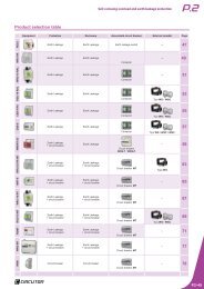
Product selection table<br />
Equipment Detuned <strong>filters</strong> Protection Connection Scope Page<br />
FRF<br />
Fixed <strong>filters</strong> By fuses Contactor 25 to 100 kvar 11<br />
FRM<br />
Fixed <strong>filters</strong> By automatic switch Contactor 25 to 100 kvar 11<br />
FR<br />
<strong>Automatic</strong> - Contactor<br />
Up to 75 kvar: FRS<br />
Up to 400 kvar: FR4<br />
Up to 600 kvar: FR6<br />
Up to 800 kvar: FR8<br />
Up to 1200 kvar: FR12<br />
7<br />
PLUS FR<br />
<strong>Automatic</strong> - Contactor<br />
Up to 75 kvar: PLUS FRS<br />
Up to 400 kvar: PLUS FR4<br />
Up to 600 kvar: PLUS FR6<br />
Up to 800 kvar: PLUS FR8<br />
Up to 1200 kvar: PLUS FR12<br />
9<br />
FRE<br />
<strong>Automatic</strong> <strong>filters</strong> - Thyristors<br />
Up to 75 kvar: FRES<br />
Up to 400 kvar: FRE4<br />
Up to 600 kvar: FRE6<br />
Up to 800 kvar: FRE8<br />
Up to 1200 kvar: FRE12<br />
13<br />
PLUS FRE<br />
<strong>Automatic</strong> <strong>filters</strong> - Thyristors<br />
Up to 75 kvar: PLUS FRES<br />
Up to 400 kvar: PLUS FRE4<br />
Up to 600 kvar: PLUS FRE6<br />
Up to 800 kvar: PLUS FRE8<br />
Up to 1200 kvar: PLUS FRE12<br />
15<br />
PLUS FRE f-f<br />
<strong>Automatic</strong> <strong>filters</strong> - Thyristors<br />
Up to 300 kvar: PLUS FREF4<br />
Up to 400 kvar: PLUS FREF6<br />
Up to 600 kvar: PLUS FREF8<br />
Up to 800 kvar: PLUS FREF12<br />
17<br />
R5/6-5
R. 5 /6 <strong>Automatic</strong> <strong>capacitor</strong> <strong>banks</strong> <strong>with</strong> <strong>detuned</strong> <strong>filters</strong><br />
R5/6-6
R .5<br />
FR<br />
Capacitor <strong>banks</strong> <strong>with</strong> <strong>detuned</strong> <strong>filters</strong><br />
Description<br />
The FR Series <strong>capacitor</strong> <strong>banks</strong> <strong>with</strong> <strong>detuned</strong><br />
<strong>filters</strong> have been designed for power compensation<br />
purposes in networks <strong>with</strong> fluctuating<br />
load levels, a high content of harmonics<br />
and where there is a risk of resonance. Power<br />
variations are relatively slow (in seconds)<br />
so that the switching operations are carried<br />
out <strong>with</strong> contactors.<br />
Application<br />
Its application is mainly focused on the compensation<br />
of installations <strong>with</strong> different loads,<br />
which require a regulated compensation, as<br />
a result of the power factor variations and<br />
where there is a high content of harmonics<br />
in the network.<br />
}}<br />
Fixed <strong>detuned</strong> <strong>filters</strong>. For the compensation<br />
of transformers and motors (FRF/<br />
FRM)<br />
}}<br />
<strong>Automatic</strong> <strong>detuned</strong> <strong>filters</strong>. For the monitoring<br />
of variable loads (FR).<br />
Features<br />
Features<br />
Operating voltage<br />
230, 400 V (for other voltages, please ask)<br />
Support voltage (400 V)<br />
440 V<br />
Capacity tolerance ± 10%<br />
••<br />
CF <strong>capacitor</strong><br />
••<br />
Contactors <strong>with</strong> pre-insertion block and quick discharge resistor<br />
••<br />
Individual protection of each step <strong>with</strong> fuses <strong>with</strong><br />
high rupture power (HRP). NH-00 Series.<br />
••<br />
Two-pole protection circuit-breaker for <strong>capacitor</strong><br />
Unit composed of bank and regulator operations.<br />
••<br />
Power factor regulator of the computer m series.<br />
••<br />
Detuned <strong>filters</strong> tuned at 189 Hz for the protection against harmonics<br />
present in the network and to avoid the problems of resonance<br />
<strong>with</strong> fifth or higher order harmonics. Built-in thermostat for the<br />
disconnection of the step in case of excessive temperatures (90 ºC).<br />
••<br />
Manual <strong>capacitor</strong> bank header switch<br />
••<br />
<strong>Automatic</strong> <strong>capacitor</strong> bank header switch<br />
••<br />
<strong>Automatic</strong> switch + Earth leakage protection at the <strong>capacitor</strong> bank's header<br />
Add-ons<br />
••<br />
Forced ventilation unit + thermostat<br />
••<br />
Polycarbonate plate to protect against direct contacts<br />
••<br />
Auto-transformer 400/230 V<br />
Insulation level<br />
3 / 15 kV<br />
Discharge resistance<br />
75 V / 3 minutes<br />
Overload<br />
1.3 times the rated current permanently<br />
••<br />
10 % 8 over 24 hours<br />
••<br />
15 % up to 15 minutes over 24 hours<br />
Overvoltage<br />
••<br />
20 % up to 5 minutes over 24 hours<br />
••<br />
30 % up to 1 minutes over 24 hours<br />
Contactor operating voltage<br />
230 V<br />
Ambient conditions<br />
Daily mean<br />
45 ºC<br />
Class D temperature<br />
Annual mean<br />
35 ºC<br />
Maximum<br />
50 ºC<br />
Minimum<br />
-25 ºC<br />
Humidity<br />
80% RH<br />
Altitude<br />
2,000 m<br />
Construction features<br />
Degree of protection IP 21<br />
Colour<br />
RAL 7035 Grey<br />
RAL 3005 Maroon<br />
Assembly conditions<br />
Type of assembly<br />
Vertical<br />
Ventilation<br />
Natural or forced, depending on the option<br />
Distance between <strong>capacitor</strong>s<br />
Minimum, 2 cm<br />
Standards<br />
CEI 60831-1, CEI 70/7, UNE 20827, UNE 20010, BS 1650, VDE 560<br />
R5-7
R.5 <strong>Automatic</strong> <strong>capacitor</strong> <strong>banks</strong> <strong>with</strong> <strong>detuned</strong> <strong>filters</strong><br />
FR<br />
Capacitor <strong>banks</strong> <strong>with</strong> <strong>detuned</strong> <strong>filters</strong><br />
Dimensions<br />
FRS<br />
FR4<br />
FR6<br />
700<br />
900<br />
100 1000<br />
380<br />
1900<br />
1900<br />
100<br />
800<br />
800<br />
100<br />
1100<br />
800<br />
FR8<br />
FR12<br />
1900<br />
1900<br />
100<br />
1500<br />
800<br />
100<br />
1100<br />
1100<br />
800<br />
R eferences<br />
kvar Composition Switch (A) Cable section Weight Dimensions (mm) Type<br />
Code<br />
440 400<br />
(mm 2 )<br />
(kg) width x height x depth<br />
17,5 14 ( 2,5 + 5 + 10 ) 63 6 105 700 x 1000 x 380 FRS-17.5-440 R5H450<br />
25 21 ( 5 + ( 2 X 10 )) 63 10 120 700 x 1000 x 380 FRS-25-440 R5H455<br />
27,5 23 ( 2.5 + 5 + ( 2 x 10 )) 125 16 130 700 x 1000 x 380 FRS-27.5-440 R5H460<br />
35 29 ( 5 + ( 3 X 10 )) 125 16 140 700 x 1000 x 380 FRS-35-440 R5H465<br />
37,5 31 ( 7.5 + ( 2 X 15 )) 125 25 150 700 x 1000 x 380 FRS-37.5-440 R5H470<br />
45 37 ( 3 x 15 ) 125 25 175 700 x 1000 x 380 FRS-45-440 R5H475<br />
60 50 ( 4 x 15 ) 200 35 200 700 x 1000 x 380 FRS-60-440 R5H480<br />
75 62 ( 4 x 18.75 ) 200 50 215 700 x 1000 x 380 FRS-75-440 R5H485<br />
87,5 72 ( 12,5 + 25 + 50 ) 200 50 300 800 x 1900 x 800 FR4-87.5-440 R5E416<br />
100 83 ( 25 + 25 + 50 ) 250 95 325 800 x 1900 x 800 FR4-100-440 R5E420<br />
125 103 ( 25 + 50 + 50 ) 400 95 345 800 x 1900 x 800 FR4-125-440 R5E422<br />
150 125 ( 25 + 25 + 50 + 50 ) 400 95 355 800 x 1900 x 800 FR4-150-440 R5E423<br />
175 145 ( 25 + 50 + 100 ) 400 120 365 800 x 1900 x 800 FR4-175-440 R5E425<br />
200 165 ( 50 + 50 + 100 ) 400 150 380 800 x 1900 x 800 FR4-200-440 R5E428<br />
250 207 ( 50 + ( 2 x 100 )) 630 185 390 800 x 1900 x 800 FR4-250-440 R5E429<br />
300 248 ( 50 + 50 + ( 2 x 100 )) 630 240 410 800 x 1900 x 800 FR4-300-440 R5E430<br />
350 289 ( 50 + ( 3 x 100 )) 800 2x150 430 800 x 1900 x 800 FR4-350-440 R5E432<br />
400 331 ( 4 x 100 ) 800 2x185 460 800 x 1900 x 800 FR4-400-440 R5E434<br />
400 331 ( 50 + 50 + ( 3 x 100 )) 800 2x185 550 1100 x 2000 x 800 FR6-400-440 R5J425<br />
450 372 ( 50 + ( 4 x 100 )) 1000 2x185 587 1100 x 2000 x 800 FR6-450-440 R5J430<br />
500 413 ( 5 x 100 ) 1000 2x240 621 1100 x 2000 x 800 FR6-500-440 R5J435<br />
550 455 ( 50 + ( 5 x 100 )) 1250 2x240 658 1100 x 2000 x 800 FR6-550-440 R5J440<br />
600 496 ( 6 x 100 ) 1250 2x240 685 1100 x 2000 x 800 FR6-600-440 R5J445<br />
600 496 ( 50 + 50 + ( 5 x 100 )) 1250 2x240 820 1500 x 2000 x 800 FR8-600-440 R5K436<br />
650 537 ( 50 + ( 6 x 100 )) 1600 3x150 865 1500 x 2000 x 800 FR8-650-440 R5K438<br />
700 579 ( 7 x 100 ) 1600 3x150 910 1500 x 2000 x 800 FR8-700-440 R5K440<br />
750 620 ( 50 + ( 7 x 100 )) 1600 3x185 955 1500 x 2000 x 800 FR8-750-440 R5K442<br />
800 661 ( 8 x 100 ) 1600 3x185 1000 1500 x 2000 x 800 FR8-800-440 R5K442<br />
800 661 ( 50 + 50 + ( 7 x 100 )) 1250 /400 2x240/ 240 1100 2200 x 2000 x 800 FR12-800-440 R5L425<br />
850 702 ( 50 + ( 8 x 100 )) 1000 / 630 2x240/ 240 1137 2200 x 2000 x 800 FR12-850-440 R5L430<br />
900 744 ( 9 x 100 ) 1250 / 630 2x240/ 240 1174 2200 x 2000 x 800 FR12-900-440 R5L435<br />
950 785 ( 50 + ( 9 x 100 )) 1000 / 800 2x240/ 2x185 1211 2200 x 2000 x 800 FR12-950-440 R5L440<br />
1000 826 ( 10 x 100 ) 1250 / 800 2x240/ 2x185 1248 2200 x 2000 x 800 FR12-1000-440 R5L445<br />
1050 868 ( 50 + ( 10 x 100 )) 1250 / 800 2x240/ 2x240 1285 2200 x 2000 x 800 FR12-1050-440 R5L450<br />
1100 909 ( 11 x 100 ) 1250 / 1000 2x240/ 2x240 1322 2200 x 2000 x 800 FR12-1100-440 R5L455<br />
1150 950 ( 50 + ( 11 x 100 )) 2 X 1250 2x240/ 2x240 1359 2200 x 2000 x 800 FR12-1150-440 R5L460<br />
1200 992 ( 12 x 100 ) 2 X 1250 2x240/ 2x240 1389 2200 x 2000 x 800 FR12-1200-440 R5L465<br />
R5-8
R .5<br />
PLUS FR<br />
Intelligent <strong>capacitor</strong> <strong>banks</strong> <strong>with</strong> <strong>detuned</strong> <strong>filters</strong><br />
Description<br />
Intelligent state-of-the-art <strong>capacitor</strong> <strong>banks</strong>,<br />
capable of measuring the three installation<br />
phases and compensating the total power<br />
factor consumption accurately.<br />
The PLUS FR series includes <strong>detuned</strong> <strong>filters</strong><br />
tuned at 189 Hz to avoid the resonance<br />
phenomena in 5th or higher order harmonics.<br />
Units for other harmonics orders are manufactured<br />
on demand.<br />
Including CIRCUTOR's measurement technology,<br />
effectively creating a compensation +<br />
measurement unit. As a power quality analyzer,<br />
it displays any electrical parameter of<br />
the network in real time and records it in its<br />
memory, <strong>with</strong> maximum and minimum values,<br />
date and hour.<br />
Application<br />
Its application is mainly focused on the compensation<br />
of installations <strong>with</strong> different loads,<br />
which require a regulated compensation, as<br />
a result of the power factor variations and<br />
where there is a high content of harmonics<br />
in the network.<br />
}}<br />
Fixed <strong>detuned</strong> <strong>filters</strong>. For the compensation<br />
of transformers and motors (FRF /FRM).<br />
}}<br />
<strong>Automatic</strong> <strong>detuned</strong> <strong>filters</strong>. For the monitoring<br />
of variable loads (PLUS FR).<br />
Features<br />
Features<br />
Operating voltage<br />
230, 400 V (for other voltages, please ask)<br />
Support voltage (400 V)<br />
440 V<br />
Capacity tolerance ± 10%<br />
••<br />
CF Capacitor<br />
••<br />
Contactors <strong>with</strong> pre-insertion block and quick discharge resistor<br />
••<br />
Individual protection of each step <strong>with</strong> fuses <strong>with</strong><br />
high rupture power (HRP). NH-00 Series.<br />
••<br />
Two-pole protection circuit-breaker for <strong>capacitor</strong><br />
bank and regulator operations.<br />
Unit composed of<br />
••<br />
Power factor regulator of the computer Plus series, threephase<br />
measurement and power analyzer functions<br />
••<br />
Detuned <strong>filters</strong> tuned at 189 Hz for the protection against harmonics<br />
present in the network and to avoid the problems of resonance<br />
<strong>with</strong> fifth or higher order harmonics. Built-in thermostat for the<br />
disconnection of the step in case of excessive temperatures (90 ºC)<br />
••<br />
Manual <strong>capacitor</strong> bank header switch<br />
••<br />
<strong>Automatic</strong> <strong>capacitor</strong> bank header switch<br />
••<br />
<strong>Automatic</strong> switch + Earth leakage protection at the <strong>capacitor</strong> bank's header<br />
Add-ons<br />
••<br />
Forced ventilation unit + thermostat<br />
••<br />
Polycarbonate plate to protect against direct contacts<br />
••<br />
Auto-transformer 400/230 V<br />
Insulation level<br />
3 / 15 kV<br />
Discharge resistance<br />
75 V / 3 minutes<br />
Overload<br />
1.3 times the rated current permanently<br />
••<br />
10 % 8 over 24 hours<br />
••<br />
15 % up to 15 minutes over 24 hours<br />
Overvoltage<br />
••<br />
20 % up to 5 minutes over 24 hours<br />
••<br />
30 % up to 1 minutes over 24 hours<br />
Contactor operating voltage<br />
230 V<br />
Ambient conditions<br />
Daily mean<br />
45 ºC<br />
Annual mean<br />
35 ºC<br />
Class D temperature<br />
Maximum<br />
50 ºC<br />
Minimum<br />
-25 ºC<br />
Humidity<br />
80% RH<br />
Altitude<br />
2,000 m<br />
Construction features<br />
Degree of protection IP 21<br />
RAL 7035 Grey<br />
Colour<br />
RAL 3005 Maroon<br />
Assembly conditions<br />
Type of assembly<br />
Vertical<br />
Ventilation<br />
Natural or forced, depending on the option<br />
Distance between <strong>capacitor</strong>s<br />
Minimum, 2 cm<br />
Standards<br />
CEI 60831-1, CEI 70/7, UNE 20827, UNE 20010, BS 1650, VDE 560<br />
R5-9
R.5 <strong>Automatic</strong> <strong>capacitor</strong> <strong>banks</strong> <strong>with</strong> <strong>detuned</strong> <strong>filters</strong><br />
PLUS FR<br />
Intelligent <strong>capacitor</strong> <strong>banks</strong> <strong>with</strong> <strong>detuned</strong> <strong>filters</strong><br />
Dimensions<br />
PLUS FRS<br />
PLUS FR4<br />
PLUS FR6<br />
700<br />
900<br />
100 1000<br />
380<br />
100<br />
1900<br />
800<br />
800 1100<br />
100<br />
1900<br />
800<br />
PLUS FR8<br />
PLUS FR12<br />
1900<br />
1900<br />
100<br />
1500<br />
800<br />
100<br />
1100<br />
1100<br />
800<br />
R eferences<br />
kvar Composition Switch (A) Cable section Weight Dimensions (mm) Type<br />
Code<br />
440 400<br />
(mm 2 )<br />
(kg) width x height x depth<br />
17,5 14 ( 2,5 + 5 + 10 ) 63 6 105 700 x 1000 x 380 PLUS FRS-17.5-440 R5G450<br />
25 21 ( 5 + ( 2 X 10 )) 63 10 120 700 x 1000 x 380 PLUS FRS-25-440 R5G455<br />
27,5 23 ( 2.5 + 5 + ( 2 x 10 )) 125 16 130 700 x 1000 x 380 PLUS FRS-27.5-440 R5G460<br />
35 29 ( 5 + ( 3 X 10 )) 125 16 140 700 x 1000 x 380 PLUS FRS-35-440 R5G465<br />
37,5 31 ( 7.5 + ( 2 X 15 )) 125 25 150 700 x 1000 x 380 PLUS FRS-37.5-440 R5G470<br />
45 37 ( 3 x 15 ) 125 25 175 700 x 1000 x 380 PLUS FRS-45-440 R5G475<br />
60 50 ( 4 x 15 ) 200 35 200 700 x 1000 x 380 PLUS FRS-60-440 R5G480<br />
75 62 ( 4 x 18.75 ) 200 50 215 700 x 1000 x 380 PLUS FRS-75-440 R5G485<br />
87,5 72 ( 12,5 + 25 + 50 ) 200 50 300 800 x 1900 x 800 PLUS FR4-87.5-440 R5D416<br />
100 83 ( 25 + 25 + 50 ) 250 95 325 800 x 1900 x 800 PLUS FR4-100-440 R5D420<br />
125 103 ( 25 + 50 + 50 ) 400 95 345 800 x 1900 x 800 PLUS FR4-125-440 R5D422<br />
150 125 ( 25 + 25 + 50 + 50 ) 400 95 355 800 x 1900 x 800 PLUS FR4-150-440 R5D423<br />
175 145 ( 25 + 50 + 100 ) 400 120 365 800 x 1900 x 800 PLUS FR4-175-440 R5D425<br />
200 165 ( 50 + 50 + 100 ) 400 150 380 800 x 1900 x 800 PLUS FR4-200-440 R5D428<br />
250 207 ( 50 + ( 2 x 100 )) 630 185 390 800 x 1900 x 800 PLUS FR4-250-440 R5D429<br />
300 248 ( 50 + 50 + ( 2 x 100 )) 630 240 410 800 x 1900 x 800 PLUS FR4-300-440 R5D430<br />
350 289 ( 50 + ( 3 x 100 )) 800 2x150 430 800 x 1900 x 800 PLUS FR4-350-440 R5D432<br />
400 331 ( 4 x 100 ) 800 2x185 460 800 x 1900 x 800 PLUS FR4-400-440 R5D434<br />
400 331 ( 50 + 50 + ( 3 x 100 )) 800 2x185 550 1100 x 2000 x 800 PLUS FR6-400-440 R5M425<br />
450 372 ( 50 + ( 4 x 100 )) 1000 2x185 587 1100 x 2000 x 800 PLUS FR6-450-440 R5M430<br />
500 413 ( 5 x 100 ) 1000 2x240 621 1100 x 2000 x 800 PLUS FR6-500-440 R5M435<br />
550 455 ( 50 + ( 5 x 100 )) 1250 2x240 658 1100 x 2000 x 800 PLUS FR6-550-440 R5M440<br />
600 496 ( 6 x 100 ) 1250 2x240 685 1100 x 2000 x 800 PLUS FR6-600-440 R5M445<br />
600 496 ( 50 + 50 + ( 5 x 100 )) 1250 2x240 820 1500 x 2000 x 800 PLUS FR8-600-440 R57436<br />
650 537 ( 50 + ( 6 x 100 )) 1600 3x150 865 1500 x 2000 x 800 PLUS FR8-650-440 R57438<br />
700 579 ( 7 x 100 ) 1600 3x150 910 1500 x 2000 x 800 PLUS FR8-700-440 R57440<br />
750 620 ( 50 + ( 7 x 100 )) 1600 3x185 955 1500 x 2000 x 800 PLUS FR8-750-440 R57442<br />
800 661 ( 8 x 100 ) 1600 3x185 1000 1500 x 2000 x 800 PLUS FR8-800-440 R57442<br />
800 661 ( 50 + 50 + ( 7 x 100 )) 1250 /400 2x240/ 240 1100 2200 x 2000 x 800 PLUS FR12-800-440 R55425<br />
850 702 ( 50 + ( 8 x 100 )) 1000 / 630 2x240/ 240 1137 2200 x 2000 x 800 PLUS FR12-850-440 R55430<br />
900 744 ( 9 x 100 ) 1250 / 630 2x240/ 240 1174 2200 x 2000 x 800 PLUS FR12-900-440 R55435<br />
950 785 ( 50 + ( 9 x 100 )) 1000 / 800 2x240/ 2x185 1211 2200 x 2000 x 800 PLUS FR12-950-440 R55440<br />
1000 826 ( 10 x 100 ) 1250 / 800 2x240/ 2x185 1248 2200 x 2000 x 800 PLUS FR12-1000-440 R55445<br />
1050 868 ( 50 + ( 10 x 100 )) 1250 / 800 2x240/ 2x240 1285 2200 x 2000 x 800 PLUS FR12-1050-440 R55450<br />
1100 909 ( 11 x 100 ) 1250 / 1000 2x240/ 2x240 1322 2200 x 2000 x 800 PLUS FR12-1100-440 R55455<br />
1150 950 ( 50 + ( 11 x 100 )) 2 X 1250 2x240/ 2x240 1359 2200 x 2000 x 800 PLUS FR12-1150-440 R55460<br />
1200 992 ( 12 x 100 ) 2 X 1250 2x240/ 2x240 1389 2200 x 2000 x 800 PLUS FR12-1200-440 R55465<br />
R5-10
R .5<br />
FRF / FRM<br />
Fixed <strong>capacitor</strong> <strong>with</strong> rejection reactance p = 7 %<br />
Description<br />
The FRF / FRM Series <strong>capacitor</strong> <strong>banks</strong> <strong>with</strong><br />
<strong>detuned</strong> <strong>filters</strong> have been designed for power<br />
compensation purposes in motors and transformers<br />
<strong>with</strong> a constant load level, a high<br />
content of harmonics and where there is a<br />
risk of resonance. Including:<br />
}}<br />
FRF: general protection <strong>with</strong> NH-00 fuses<br />
<strong>with</strong> a high rupture power (HRP) for the <strong>capacitor</strong>.<br />
}}<br />
FRM: general circuit breaker protection<br />
for the <strong>capacitor</strong>.<br />
Application<br />
Its application is mainly based on the compensation<br />
of transformers and motors. In<br />
general, it is used for the compensation of<br />
installations under constant loads and where<br />
there is a high content of harmonics in the<br />
network.<br />
Features<br />
Features<br />
Operating voltage<br />
230, 400 (for other voltages, please ask)<br />
Support voltage (400 V)<br />
440 V<br />
Capacity tolerance ±10%<br />
••<br />
CF Capacitor<br />
••<br />
FRF: General protection fuse, type<br />
••<br />
NH-00 <strong>with</strong> a high rupture power (HRP)<br />
••<br />
FRM: General three-pole protection circuit breaker<br />
Unit composed of<br />
••<br />
Detuned <strong>filters</strong> tuned at 189 Hz for the protection<br />
against harmonics present in the network and to avoid<br />
the problems of resonance <strong>with</strong> fifth or higher order<br />
harmonics. Built-in thermostat for the disconnection<br />
of the step in case of excessive temperatures (90 ºC)<br />
Insulation level<br />
3 / 15 kV<br />
Discharge resistance<br />
75 V / 3 minutes<br />
Overload<br />
1.3 times the rated current permanently<br />
••<br />
10 % 8 over 24 hours<br />
••<br />
15 % up to 15 minutes over 24 hours<br />
Overvoltage<br />
••<br />
20 % up to 5 minutes over 24 hours<br />
••<br />
30 % up to 1 minute over 24 hours<br />
Frequency<br />
50 or 60 Hz<br />
••<br />
Dielectric<br />
< 0.2 W / kvar<br />
Losses:<br />
••<br />
Total<br />
< 0.5 W / kvar<br />
••<br />
Dielectric regeneration<br />
••<br />
Internal fuse<br />
Protections<br />
••<br />
Overpressure system<br />
••<br />
Vermiculite<br />
Construction features<br />
Terminals:<br />
Torque value<br />
Ambient conditions<br />
Class D temperature:<br />
••<br />
Power rating<br />
••<br />
Earth<br />
Daily mean<br />
Annual mean<br />
Maximum<br />
Minimum<br />
••<br />
M6 for CV, M10 for CQ, CS, CS-6B, CF, CF-6B<br />
••<br />
M6<br />
••<br />
CV 5 Nm<br />
••<br />
CQ, CS, CS-6B, CF, CF-6B: 15 Nm<br />
45 ºC<br />
35 ºC<br />
50 o C<br />
-25 ºC<br />
80% RH<br />
2,000 m<br />
Humidity<br />
Altitude<br />
Assembly conditions<br />
Degree of protection IP 21<br />
Type of assembly<br />
Vertical<br />
Ventilation<br />
Natural or forced, depending on the option<br />
RAL 7035 Grey<br />
Colour<br />
RAL 3005 Maroon<br />
Standards<br />
CEI 60831-1, CEI 70/7, UNE 20827, UNE 20010, BS 1650, VDE 560<br />
R5-11
R.5 <strong>Automatic</strong> <strong>capacitor</strong> <strong>banks</strong> <strong>with</strong> <strong>detuned</strong> <strong>filters</strong><br />
FRF / FRM<br />
Fixed <strong>capacitor</strong> <strong>with</strong> rejection<br />
reactance p = 7 %<br />
Dimensions<br />
100 960<br />
1060<br />
20<br />
610<br />
650<br />
20<br />
420<br />
INPUTS ENTRADAS<br />
R eferences<br />
440 V / 50 Hz<br />
FRF: APR Fuse protection<br />
kvar<br />
(A)<br />
440 V 400 V<br />
Weight (kg)<br />
Cable section<br />
(mm 2 )<br />
Dimensions (mm)<br />
width x height x depth<br />
25 21 33 78 10 650 x 1060 x 420 FRF-25-440 R55350<br />
37,5 31 47 82 16 650 x 1060 x 420 FRF-37.5-440 R55370<br />
50 42 66 85 25 650 x 1060 x 420 FRF-50-440 R55380<br />
60 50 79 90 35 650 x 1060 x 420 FRF-60-440 R55390<br />
75 62 99 96 50 650 x 1060 x 420 FRF-75-440 R553A0<br />
100 83 131 110 70 650 x 1060 x 420 FRF-100-440 R553B0<br />
Type<br />
Code<br />
440 V / 50 Hz<br />
FRM: Three-pole automatic protection<br />
kvar<br />
(A)<br />
440 V 400 V<br />
Weight (kg)<br />
Cable section<br />
(mm 2 )<br />
Dimensions (mm)<br />
width x height x depth<br />
25 21 33 78 10 650 x 1060 x 420 FRM-25-440 R57350<br />
37,5 31 47 82 16 650 x 1060 x 420 FRM-37.5-440 R57370<br />
50 42 66 85 25 650 x 1060 x 420 FRM-50-440 R57380<br />
60 50 79 90 35 650 x 1060 x 420 FRM-60-440 R57390<br />
75 62 99 96 50 650 x 1060 x 420 FRM-75-440 R573A0<br />
100 83 131 110 70 650 x 1060 x 420 FRM-100-440 R573B0<br />
Type<br />
Code<br />
R5-12