1.5KW/2KW PV Inverter User Manual - Voltron
1.5KW/2KW PV Inverter User Manual - Voltron
1.5KW/2KW PV Inverter User Manual - Voltron

Create successful ePaper yourself
Turn your PDF publications into a flip-book with our unique Google optimized e-Paper software.
<strong>User</strong> <strong>Manual</strong><br />
<strong>1.5KW</strong>/<strong>2KW</strong> <strong>PV</strong> <strong>Inverter</strong>
Table Of Contents<br />
1. Introduction ......................................................................................................... 1<br />
1-1. Overview ..................................................................................................... 1<br />
1-2. Affecting Factors for Performance of the <strong>Inverter</strong> ............................................ 1<br />
2. Important Safety Warning ..................................................................................... 2<br />
3. Unpacking & Overview .......................................................................................... 4<br />
3-1. Packing List .................................................................................................. 4<br />
3-2. Product Overview.......................................................................................... 4<br />
4. Installation ........................................................................................................... 5<br />
4-1. Selecting Mounting Location .......................................................................... 5<br />
4-2. Mounting Unit with Wall Mounting Bracket ...................................................... 5<br />
5. Grid (AC) Connection ............................................................................................ 6<br />
5-1. Preparation .................................................................................................. 6<br />
5-2. Connecting to the AC Utility ........................................................................... 6<br />
6. <strong>PV</strong> Module (DC) Connection ................................................................................... 8<br />
7. Communication ................................................................................................... 11<br />
8. Commissioning .................................................................................................... 12<br />
9. Operation ........................................................................................................... 13<br />
9-1. Interface ..................................................................................................... 13<br />
9-2. LCD Information Define ................................................................................ 13<br />
9-3. Operation Button ......................................................................................... 14<br />
9-4 Query Menu Operation .................................................................................. 14<br />
9-5. Operation Mode & Display ............................................................................ 15<br />
10. Maintenance & Cleaning ....................................................................................... 16<br />
11. Trouble Shooting ................................................................................................... 17<br />
11-1. Warning Situation ...................................................................................... 17<br />
11-2. Fault Reference Codes ................................................................................ 17<br />
12. Specifications ........................................................................................................ 20
1. Introduction<br />
1-1. Overview<br />
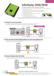
This <strong>PV</strong> inverter is designed to convert solar electric (photovoltaic or <strong>PV</strong>) power into<br />
utility-grade electricity that can be sold to the local power company. This inverter is embedded<br />
with smart MPP tracker to allow the <strong>PV</strong> inverter to operate at optimum power output voltage.<br />
<strong>PV</strong> module<br />
<strong>PV</strong> inverter<br />
Distribution Box<br />
Electric grids<br />
Figure 1 Basic <strong>PV</strong> System Overview<br />
This inverter is only compatible with <strong>PV</strong> module types of single crystalline and poly crystalline.<br />
Do not connect any sources of energy other than these two types of <strong>PV</strong> modules to the<br />
inverter. When designing the <strong>PV</strong> system, ensure that the values comply with the permitted<br />
operating range of all components at all times. See Figure 1 for a simple diagram of a typical<br />
<strong>PV</strong> system with the <strong>Inverter</strong>.<br />
1-2. Affecting Factors for Performance of the <strong>Inverter</strong><br />
There are a lot of factors to influence the performance of this inverter.<br />
Rating for <strong>PV</strong> Modules<br />
<strong>PV</strong> modules are rated at ideal factory conditions, such as specified illumination (1000 W/m2),<br />
spectrum of the light and temperature (25 °C / 77 °F). This is called the STC (Standard Test<br />
Condition) rating and is the figure that appears on the spec label of <strong>PV</strong> module. Generally<br />
speaking, only around 60% to 70% of its peak STC-rated output will be produced from your<br />
<strong>PV</strong> modules due to unpredicted environmental factors.<br />
Temperature and Power Reduction<br />
Environment temperature affects the power output of <strong>PV</strong> modules. Higher the temperature,<br />
lower the power output of <strong>PV</strong> module. Comparing with pole-mounted <strong>PV</strong> module array,<br />
roof-mounted <strong>PV</strong> module array generates less power due to less air circulation and excess<br />
heat from roof top.<br />
1
Important: The inverter will reduce its output generation to protect its electronic circuits<br />
from overheating and any damage under high temperature environment. For maximum<br />
power output in high temperature, it’s recommended to mount the inverter in a shaded<br />
location with good ventilation.<br />
Angle of the Sun<br />
The angle of the sun in relation to the <strong>PV</strong> array surface—the array orientation can dramatically<br />
affect the <strong>PV</strong> array output. The array energy output will vary depending on the time of day<br />
and time of year as the sun’s angle in relation to the array changes. Sunlight output decreases<br />
as the sun approaches the horizons (such as in winter in Europe) due to the greater<br />
atmospheric air mass it must penetrate, reducing both the light intensity that strikes the<br />
array’s surface and spectrum of the light. In general, you can expect only four to six hours of<br />
direct sunlight per day depending on what part of Europe the inverter is installed.<br />
Partial Shade<br />
Shading on a single <strong>PV</strong> module of the array will reduce the output power of the entire system.<br />
Such shading can be caused by something as simple as the shadow of a utility wire or tree<br />
branch on part of the array’s surface. This condition, in effect, acts like a weak battery in a<br />
flashlight, reducing the total output, even though the other batteries are good. However, the<br />
output loss is not proportionate to shading even a tiny bit of shading will reduce the <strong>PV</strong> power<br />
to the inverter. The inverter is designed to maximize its power production in all of the above<br />
situations using its proprietary MPPT algorithm.<br />
Other Factors<br />
Other factors to reduce power generation of a solar system are:<br />
• Dust or dirt on the modules<br />
• Fog or smog<br />
• Mismatched <strong>PV</strong> array modules, with slight inconsistencies in performance from one<br />
module to another.<br />
• <strong>Inverter</strong> efficiency<br />
• Wire losses<br />
• Utility grid voltage<br />
2. Important Safety Warning<br />
Before using the inverter, please read all instructions and cautionary markings on<br />
the unit and this manual. Store the manual where it can be accessed easily.<br />
This manual is for qualified personnel. The tasks described in this manual may be performed<br />
by qualified personnel only.<br />
General Precaution-<br />
Conventions used:<br />
WARNING! Warnings identify conditions or practices that could result in personal injury;<br />
CAUTION! Caution identify conditions or practices that could result in damaged to the<br />
unit or other equipment connected.<br />
2
WARNING! Before installing and using this inverter, read all instructions and cautionary<br />
markings on the inverter and all appropriate sections of this guide.<br />
WARNING! Normally grounded conductors may be ungrounded and energized when a<br />
ground fault is indicated.<br />
WARNING! This inverter is heavy. It should be lifted by at least two persons.<br />
CAUTION! Authorized service personnel should reduce the risk of electrical shock by<br />
disconnecting both the AC and DC power from the inverter before attempting any<br />
maintenance or cleaning or working on any circuits connected to the inverter. Turning off<br />
controls will not reduce this risk. Internal capacitors can remain charged for 5 minutes after<br />
disconnecting all sources of power.<br />
CAUTION! Do not disassemble this inverter yourself. It contains no user-serviceable parts.<br />
Attempt to service this inverter yourself may cause a risk of electrical shock or fire and will<br />
void the warranty from the manufacturer.<br />
CAUTION! To avoid a risk of fire and electric shock, make sure that existing wiring is in good<br />
condition and that the wire is not undersized. Do not operate the <strong>Inverter</strong> with damaged or<br />
substandard wiring.<br />
CAUTION! Under high temperature environment, heat sink of this inverter could be hot<br />
enough to cause skin burns if accidentally touched. Ensure that this inverter is away from<br />
normal traffic areas.<br />
CAUTION! Use only recommended accessories from installer . Otherwise, not-qualified tools<br />
may cause a risk of fire, electric shock, or injury to persons.<br />
CAUTION! To reduce risk of fire hazard, do not cover or obstruct the heat sink.<br />
CAUTION! Do not operate the <strong>Inverter</strong> if it has received a sharp blow, been dropped, or<br />
otherwise damaged in any way. If the <strong>Inverter</strong> is damaged, called for an RMA (Return Material<br />
Authorization).<br />
3
3. Unpacking & Overview<br />
3-1. Packing List<br />
Before installation, please inspect the unit. Be sure that nothing inside the package is<br />
damaged. You should have received the following items inside of package:<br />
<strong>Inverter</strong> unit <strong>PV</strong> connectors AC connector Mounting Software CD <strong>Manual</strong> USB cable<br />
plate<br />
3-2. Product Overview<br />
1) LCD display panel (Please check section 8 for detailed LCD operation)<br />
2) Operation button<br />
3) Connectors for solar modules<br />
4) Intelligent slot with USB communication port<br />
5) AC output terminal<br />
4
4. Installation<br />
4-1. Selecting Mounting Location<br />
Consider the following points before selecting where to install:<br />
• Do not mount the inverter on flammable construction materials.<br />
• Mount on a solid surface<br />
• Although the unit is fitted with UV resistant components, direct exposure to sunlight<br />
may cause a power reduction due to excessive heating.<br />
• This inverter can make noises during operation which may be perceived as a nuisance in<br />
a living area.<br />
• Install this inverter at eye level in order to allow the LCD display to be read at all times.<br />
• For proper air circulation to dissipate heat, allow a clearance of approx. 20 cm to the<br />
side and approx. 50 cm above and below the unit.<br />
• Dusty conditions on the unit may impair the performance of this inverter.<br />
• The ambient temperature should be between -25°C and 60°C to ensure optimal<br />
operation.<br />
• The recommended installation position is to be adhered to (vertical).<br />
• Unused DC connectors and interfaces must be sealed with sealing plugs to ensure<br />
protection class IP65 for the whole system (inverter & cables).<br />
• This inverter is designed with IP65 for outdoor applications with high humidity.<br />
WARNING!! Remember that this inverter is heavy! Please be carefully when lifting out<br />
from the package.<br />
4-2. Mounting Unit with Wall Mounting Bracket<br />
Please utilize the delivered mounting plate for problem-free installation of the solar inverter.<br />
Installation to the wall should be implemented with the proper screws. Mount the wall bracket<br />
so that the solar inverter can be easily attached to the wall. After that, the device should be<br />
bolted on securely.<br />
1. Mount the mounting plate with<br />
appropriate screws (M5,SUS304) into<br />
four holes to fix the plate in place.<br />
2. Put solar inverter onto the mounting<br />
plate.<br />
5
3. Screw the inverter in position by screwing<br />
the supplied M5 screw, located on the<br />
underside of the enclosure.<br />
4. Check if the solar inverter is firmly<br />
secured.<br />
5. Grid (AC) Connection<br />
5-1. Preparation<br />
Before connecting to AC utility, please install a separate AC circuit breaker between inverter<br />
and AC utility. This will ensure the inverter can be securely disconnected under load.<br />
NOTE1: Although this inverter is equipped with a fuse (F1 point on PCB, 250VAC/20A), it’s<br />
still necessary to install a separate circuit breaker for safety consideration. Please use<br />
250VAC/20A circuit breaker.<br />
NOTE2: If you want to add a manual RCMU, it shall be type B.<br />
WARNING! It's very important for system safety and efficient operation to use appropriate<br />
cable for grid connection. To reduce risk of injury, please use the proper recommended cable<br />
size as below.<br />
Suggested cable requirement for AC wire<br />
Model External Conductor cross-section AWG no. Temperature<br />
Diameter(mm) (mm 2 )<br />
1.5kW/2kW ≦4.5 ≥3.3 ≤12 125°C<br />
5-2. Connecting to the AC Utility<br />
Overview of AC Connection Socket<br />
A<br />
B<br />
C D E<br />
F<br />
Cable gland<br />
6
Component<br />
A<br />
B<br />
C<br />
D<br />
E<br />
F<br />
Description<br />
AC output terminal on the inverter<br />
Socket element<br />
Protective element<br />
Threaded sleeve<br />
Sealing nut<br />
Pressure dome<br />
Step 1: Check the grid voltage and frequency with an AC voltmeter. It should be the same to<br />
“VAC” value on the product label.<br />
Step 2: Turn off the circuit breaker.<br />
Step 3: Insert sealing nut (E) inside of threaded sleeve (D). Then, screw pressure dome (F)<br />
tightly onto the assembled threaded sleeve. (Refer to Chart 1)<br />
Step 4: Thread the protective element (C) with assembled cable gland over the utility cable.<br />
(Refer to Chart 1)<br />
F<br />
E<br />
D<br />
C<br />
Chart 1<br />
Step 5: Remove insulation sleeve 8 mm for three conductors. And shorten phase L and neutral<br />
conductor N 3 mm.<br />
Step 6: Insert utility cable through socket element (B) and tighten the screw to fix utility cable.<br />
And push protective element (C) onto the socket element (B) until it audibly snaps into place.<br />
B<br />
screw<br />
Step 7: Connect wires according to polarities indicated on AC output terminal on the inverter<br />
and tighten the screws after connection.<br />
L→LINE (brown or black)<br />
G→Ground (yellow-green)<br />
N→Neutral (blue)<br />
7
Step 8: Twist the gland so that the cable is firmly connected.<br />
CAUTION: To prevent risk of electric shock, ensure the ground wire is properly earthed<br />
before operating the solar inverter.<br />
6. <strong>PV</strong> Module (DC) Connection<br />
CAUTION: Before connecting to <strong>PV</strong> modules, please install separately a 2P DC circuit<br />
breakers between inverter and <strong>PV</strong> modules.<br />
NOTE: Please use 600VDC/15A circuit breaker.<br />
Please follow below steps to implement <strong>PV</strong> module connection:<br />
WARNING: This inverter is only compatible to two types of <strong>PV</strong> modules: single crystalline<br />
and poly crystalline. To avoid any malfunction, do not connect any <strong>PV</strong> modules with<br />
possibility of leakage current to the inverter.<br />
Step 1: Assemble provided <strong>PV</strong> connectors into <strong>PV</strong> modules by following below steps.<br />
Cable preparation and stripping process:<br />
Strip cable 0.276 inches (7.0 mm) and be careful NOT to nick<br />
conductors. Amphenol specified strip tool can be used in this step.<br />
Adjust the striper stopper and put the cable in corresponding notch<br />
to strip the length of 7mm.See below picture 1 and 2.<br />
Insert striped cable into contact barrel and ensure all conductor strands are captured in the<br />
contact barrel. See below pictures 3 and 4.<br />
8
Crimp contact barrel by using the crimping die, and be careful NOT to hurt the second row<br />
wings. See below pictures 5 and 6 for crimping result.<br />
Amphenol specified crimp tool can be used in this step. The pull-out forces requirement is<br />
listed as the following:<br />
Cable size<br />
Cable pull-out force requirement<br />
2.5 mm 2 Min. 230 N (~50Lbs)<br />
4.0 mm 2 Min. 310 N (~70Lbs)<br />
6.0 mm 2 Min. 360 N (~80Lbs)<br />
Connector assembly process:<br />
Insert assembled contact cable into back of male and female connector. A ”click” should be<br />
heard or felt when the assembled contact cable is seated in correct position. Contacts cannot<br />
be removed once seated. See below pictures 7-10.<br />
Female coupler<br />
Male Coupler<br />
Back cap must be locked by using a torque between 2.6 and 2,9NM. Amphenol specified hand<br />
wrench tool can be used in this step or electric torque controlled wrench tool with as well the<br />
Amphenol open-end back cap spanner or socket wrench. See below picture 11 and 12 for<br />
hand wrench.<br />
9
Note: Pneumatic wrench tools are NOT recommended since torque control is very difficult.<br />
Step 2: Check the input voltage of <strong>PV</strong> array modules. The acceptable input voltage of the solar<br />
inverter is 125VDC - 450VDC for <strong>1.5KW</strong> and 125VDC - 450VDC for <strong>2KW</strong>. Please make sure<br />
maximum input current should not exceed 11A.<br />
CAUTION: Exceeding the maximum input voltage can destroy the unit!! Check the system<br />
before wire connection.<br />
Step 3: Disconnect the circuit breaker.<br />
Step 4: Check correct polarity of connection cable from <strong>PV</strong> modules and <strong>PV</strong> input connectors.<br />
Then, connect positive pole (+) of connection cable to positive pole (+) of <strong>PV</strong> input connector.<br />
Connect negative pole (-) of connection cable to negative pole (-) of <strong>PV</strong> input connector.<br />
WARNING! It's very important for system safety and efficient operation to use appropriate<br />
cable for grid connection. To reduce risk of injury, please use the proper recommended cable<br />
size as below.<br />
Suggested cable requirement for DC wire<br />
Model External Conductor cross-section AWG no. Temperature<br />
Diameter(mm) (mm 2 )<br />
1.5kW/2kW ≦6.0 ≥3.3 ≤12 125°C<br />
CAUTION: Never directly touch terminals of the inverter. It will cause lethal electric shock.<br />
10
7. Communication<br />
This inverter is equipped with a slot for communication interfaces in order to communicate<br />
with a PC (personal computer) with corresponding software. Follow below procedure to<br />
connect communication wiring and install the software.<br />
Step 1: Take out communication cover by removing 4 screws.<br />
Step 2: There are two kinds of ports available: RS-232 and USB. You may use supplied USB<br />
cable to connect USB port of this inverter and your PC (personal computer). Or you may use<br />
one network cable (RJ-45) to connect RS-232 port of this inverter and your PC (personal<br />
computer).<br />
Step 3: Install monitoring software in your PC (personal computer). For the details of<br />
monitoring software, please check with the installer.<br />
Step 4: Initial your monitoring software and extract data through communication port. After<br />
completing data acquisition, please put the communication port back to the unit.<br />
11
8. Commissioning<br />
Step 1: Check the following requirements before commissioning:<br />
• Ensure the inverter is firmed secured<br />
• Check if the open circuit DC voltage of <strong>PV</strong> module meets requirement (Refer to Section<br />
6)<br />
• Check if the open circuit utility voltage of the utility is at approximately same to the<br />
nominal expected value from local utility company.<br />
• Correct connection to grid<br />
• Full connection to <strong>PV</strong> modules<br />
• Unused DC input connectors are sealed with supplied sealing plugs.<br />
• AC circuit breaker and DC circuit breaker are installed correctly.<br />
Step 2: After switching on the DC circuit breakers, it will display “No Utility” in the LCD screen.<br />
Then, switch on the AC circuit breakers. After 60 seconds, the system will automatically<br />
connect to the grid. Then:<br />
• If inverter icon is in the LCD display like below, commissioning has been successfully.<br />
• Or, if icon flashes, there is insufficient radiation and the inverter is in standby<br />
mode. Wait for sufficient radiation.<br />
• Or, if icon flashes, the grid voltage or frequency is beyond acceptable range<br />
and the inverter is in standby mode. Wait for grid voltage or frequency to return to<br />
acceptable range.<br />
• Or if icon flashes, there has been an error. Please check chapter 10 for trouble<br />
shooting. If the problem still resists, please inform your installer.<br />
Step 3: Use supplied USB cable to connect the inverter and your computer, and start<br />
monitoring software installed in your computer.<br />
12
9. Operation<br />
9-1. Interface<br />
This LCD panel shows current status and value of your system. This display is operated by<br />
Information/SELECT button.<br />
NOTICE: To accurately monitor and calculate the energy generation, please calibrate the<br />
timer of this unit via software every one month. For the detailed calibration, please check the<br />
user manual of bundled software.<br />
9-2. LCD Information Define<br />
Display<br />
Function<br />
Indicates input voltage of <strong>PV</strong> module.<br />
V: voltage<br />
Indicates AC output voltage or frequency.<br />
V: voltage, Hz: frequency<br />
Indicates current feeding power.<br />
Indicates energy generated today.<br />
Indicates total energy generated so far.<br />
Indicates that the warning occurs.<br />
Indicates that the fault occurs.<br />
Indicates fault code in fault mode or WR for warning<br />
situation.<br />
13
9-3. Operation Button<br />
Indicates <strong>PV</strong> module status.<br />
• Each indicates 150VDC. When input voltage is<br />
below 100VDC, icon will flash.<br />
• When <strong>PV</strong> module is not connected, icon will<br />
flash.<br />
Indicates the <strong>Inverter</strong> circuit is working.<br />
Indicates grid.<br />
The INFORMATION/SELECT button controls LCD settings and has three functions.<br />
Function Operation Description<br />
Information<br />
changes<br />
Press the button once<br />
To jump to next selection or<br />
decrease value.<br />
Query Menu Press and hold the button for 2 To enter query menu<br />
seconds<br />
Selection<br />
confirmed<br />
Press and hold the button for 2<br />
seconds<br />
To confirm selection or<br />
value entry in query menu.<br />
NOTE: If backlight shuts off, you may activate it by pressing any button.<br />
9-4 Query Menu Operation<br />
This display shows current values of your system. These displayed values can be changed in<br />
query menu via button operation. Press “INFORMATION/SELECT” button to enter query menu.<br />
There are two query selections:<br />
• Frequency or voltage of AC output<br />
• Power generation today or total power generation since installation.<br />
Frequency or voltage of AC output<br />
Voltage of AC output<br />
Procedure<br />
LCD Display<br />
Frequency of AC output<br />
Procedure<br />
LCD Display<br />
14
Power generation<br />
Power generation today<br />
Procedure<br />
LCD Display<br />
Total power generation since installation<br />
Procedure<br />
LCD Display<br />
9-5. Operation Mode & Display<br />
Mode LCD Display Description<br />
Power on<br />
mode<br />
The inverter is initializing.<br />
Grid mode<br />
The inverter is feeding<br />
power to the grid.<br />
Standby<br />
mode<br />
The inverter is waiting for<br />
the DC voltage to reach a<br />
certain level so that it can<br />
start feeding the grid.<br />
15
Fault mode<br />
An error occurs inside of<br />
the inverter. Please inform<br />
your installer.<br />
, and icons will flash.<br />
10. Maintenance & Cleaning<br />
Check the following points to ensure proper operation of whole solar system at regular<br />
intervals.<br />
• Heat sink of the inverter should be cleaned from dust.<br />
WARNING: Although the inverter is designed in sealed IP65 enclosure, it is not<br />
recommended to use a pressure washer to clean the inverter, or use other high pressure<br />
cleaning methods that could allow water or moisture to enter the unit.<br />
• Clean the <strong>PV</strong> modules, during the cool time of the day, whenever it is visibly dirty.<br />
• Periodically inspect the system to make sure that all wires and supports are securely<br />
fastened in place.<br />
WARNING: There are no user-replaceable parts inside of the inverter. Do not attempt to<br />
service the unit yourself.<br />
16
11. Trouble Shooting<br />
When there is no information displayed in the LCD, please check if <strong>PV</strong> module connection is<br />
correctly connected.<br />
11-1. Warning Situation<br />
There are 5 situations defined as warnings. When a warning situation occurs,<br />
flash and the fault code area will display “WR” wordings.<br />
No <strong>PV</strong> module is connected<br />
flash failure<br />
<strong>Inverter</strong> initial failure<br />
Line loss<br />
Islanding is detected<br />
icon will<br />
11-2. Fault Reference Codes<br />
When a fault occurs, the icon will flash as a reminder. See below for fault codes for<br />
reference.<br />
Situation<br />
Fault<br />
Icon<br />
Solution<br />
Fault Event<br />
Code<br />
(flashing)<br />
1 Over voltage on Bus 1. Disconnect AC circuit breaker<br />
2 Under voltage on Bus<br />
first. Then, disconnect DC<br />
3 Time out for Bus soft start<br />
circuit breaker.<br />
4 Time out for <strong>Inverter</strong> soft<br />
start<br />
2. Until LCD screen completely<br />
shuts down, turn on DC<br />
5 <strong>Inverter</strong> over current<br />
breaker first. It will show “No<br />
7 Relay fault<br />
Utility” in LCD screen. Then,<br />
8 Output current sensor<br />
failure<br />
turn on AC breaker. After 60<br />
seconds, the system will<br />
10 Power failure<br />
automatically connect to the<br />
11 DC input over current<br />
grid.<br />
3. If the error message still<br />
14 <strong>Inverter</strong> DC current over<br />
remains, please contact your<br />
16 GFCI sensor failure<br />
installer.<br />
6 Over temperature 1. The internal temperature is<br />
higher than specified<br />
temperature.<br />
2. Leave inverter to be cooled<br />
to room temperature.<br />
3. If the error message still<br />
remains, please contact your<br />
installer.<br />
17
Situation<br />
Fault<br />
Icon<br />
Solution<br />
Fault Event<br />
Code<br />
(flashing)<br />
9 High voltage on <strong>PV</strong> module 1. Check if the open circuit<br />
voltage of <strong>PV</strong> modules is<br />
higher than 450VDC for<br />
<strong>1.5KW</strong> or 500VDC for <strong>2KW</strong>.<br />
2. If <strong>PV</strong> open circuit voltage is<br />
less than 450VDC for <strong>1.5KW</strong><br />
or 500VDC for <strong>2KW</strong> and the<br />
error message remains,<br />
pelase contact your installer.<br />
12 GFCI failure 1. The ground voltage is too<br />
high.<br />
2. Please disconnect AC<br />
breaker first and then DC<br />
breaker. Check if grounding<br />
is connected properly after<br />
LCD screen completely shuts<br />
down.<br />
3. If grounding is correctly<br />
connected, turn on DC<br />
brearker. After it displays<br />
“No Utility” in LCD screen,<br />
turn on AC breaker. After 60<br />
seconds, the system will<br />
automatically connect to the<br />
grid.<br />
4. If the error message still<br />
remains, please contact your<br />
installer.<br />
13 <strong>PV</strong> insulation failure 1. Check if the impedance<br />
between positive and<br />
negative poles to the ground<br />
is greater than 1MΩ.<br />
2. If the impedance is lower<br />
than 1MΩ, please contact<br />
your installer.<br />
18
Situation<br />
Fault<br />
Fault Event<br />
Code<br />
15 Line value consistent fail<br />
between MCU & DSP<br />
17 Connection failure between<br />
MCU & DSP<br />
18 Communication failure<br />
between MCU & DSP<br />
Icon<br />
(flashing)<br />
Solution<br />
1. Please disconnect AC<br />
breaker first and then<br />
disconnect DC breaker.<br />
2. After LCD screen is<br />
completely off, turn on DC<br />
breaker. Until it shows “No<br />
Utility” in LCD display, turn<br />
on AC breaker. After 60<br />
seconds, the system will<br />
automatically connect to the<br />
grid.<br />
3. If error message remains,<br />
please contact your installer.<br />
19 Ground loss 1. Check if the inverter is<br />
connected to the ground.<br />
2. If ground is properly<br />
connected and the error<br />
message remains, please<br />
contact your installer.<br />
No display in LCD screen. 1. Check input voltage of <strong>PV</strong><br />
modules.<br />
2. If input voltage is higher<br />
than 150VDC, please<br />
contact your installer.<br />
Time display in LCD screen changes quickly or<br />
slowly.<br />
1. Please calibrate the timer<br />
via software.<br />
2. If the problem remains after<br />
calibration, please contact<br />
your installer.<br />
<strong>Inverter</strong> is turned on and turned off in turns. 1. It’s normal situation due to<br />
insufficient radiation in the<br />
short-term time.<br />
19
12. Specifications<br />
MODEL <strong>1.5KW</strong> <strong>2KW</strong><br />
INPUT (DC)<br />
Max. DC Power 1650W 2200W<br />
Maximum DC Voltage 450 VDC 500 VDC<br />
MPP Voltage Range 150 VDC ~ 400 VDC 200 VDC ~ 450 VDC<br />
DC Nominal Voltage 360 VDC 360 VDC<br />
Start-up Voltage / Initial Feeding Voltage 125VDC / 150VDC 125VDC / 150VDC<br />
Maximum Input Current 1 x 11 A 1 x 11 A<br />
Number of MPP Trackers / Strings per MPP<br />
Tracker<br />
1 / A: 1 1 / A: 1<br />
OUTPUT (AC)<br />
AC Nominal Power 1500 W 2000 W<br />
Maximum AC Apparent Power 1500 VA 2000 VA<br />
Nominal AC Voltage / Range<br />
230 VAC / 184 VAC ~ 230 VAC / 184 VAC ~<br />
264 VAC<br />
264 VAC<br />
AC Grid Frequency 50 Hz 50 Hz<br />
AC Grid Frequency Range 47.5~ 51.5 Hz 47.5~ 51.5 Hz<br />
Nominal Output Current 6.6A 8.7A<br />
Power Factor @ > 50% load > 0.99 > 0.99<br />
EFFICIENCY<br />
Maximum Efficiency @ Nominal Voltage 96% 96%<br />
European Efficiency @ Nominal Voltage 95% 95%<br />
PROTECTION<br />
DC Reverse-Polarity Protection Yes Yes<br />
Ground Fault Monitoring Yes Yes<br />
Grid Monitoring Yes Yes<br />
AC Short Circuit Protection Yes Yes<br />
PHYSICAL<br />
Dimension, D X W X H (mm) 410 x 270 x 155 410 x 270 x 155<br />
Net Weight (kgs) 12 12<br />
INTERACE<br />
Intelligent Slot<br />
USB & RS-232 card /<br />
Optional SNMP &<br />
Modbus card<br />
USB & RS-232 card /<br />
Optional SNMP &<br />
Modbus card<br />
ENVIRONMENT<br />
Protection Degree<br />
IP65/Pollution Degree IP65/Pollution Degree<br />
Ⅲ<br />
Ⅲ<br />
Humidity 0 ~ 100% 0 ~ 100%<br />
Operating Temperature -25°C to 60°C* -25°C to 60°C*<br />
Altitude 0 ~ 1000 m 0 ~ 1000 m<br />
* When temperature is above 75°C, the unit will de-rate according to the below formula:<br />
P=P Rating x [110%-(T-75)x10%].<br />
20