
You also want an ePaper? Increase the reach of your titles
YUMPU automatically turns print PDFs into web optimized ePapers that Google loves.
®<br />
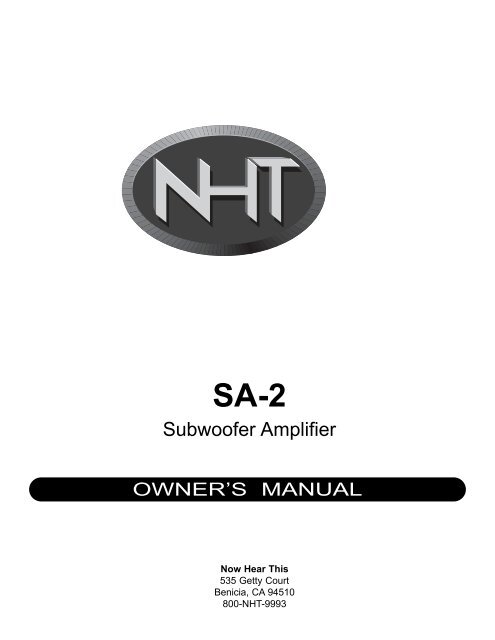
SA-2<br />
Subwoofer Amplifier<br />
OWNER’S MANUAL<br />
Now Hear This<br />
535 Getty Court<br />
Benicia, CA 94510<br />
800-<strong>NHT</strong>-9993
IMPORTANT SAFETY INSTRUCTIONS<br />
CAUTION<br />
RISK OF ELECTRIC SHOCK<br />
DO NOT OPEN<br />
CAUTION: TO REDUCE RISK OF ELECTRICAL SHOCK, DO NOT REMOVE COVER (OR BACK). NO<br />
USER SERVICEABLE PARTS INSIDE. REFER TO QUALIFIED SERVICE PERSONNEL.<br />
The lightning flash with the arrowhead symbol, within an equilateral triangle, is intended to alert the user to the presence of uninsulated<br />
“dangerous voltage” within the product’s enclosure that may be of sufficient magnitude to constitute a risk of electric shock to persons.<br />
The exclamation point within an equilateral triangle is intended to alert the user to the presence of important operating and maintenance<br />
(servicing) instructions in the literature accompanying the appliance.<br />
WARNING: TO REDUCE THE RISK OF FIRE OR ELECTRIC SHOCK, DO NOT EXPOSE THIS APPLIANCE TO RAIN OR MOISTURE.<br />
1. READ INSTRUCTIONS - All safety and operating instructions should be read before the appliance is operated.<br />
2. RETAIN INSTRUCTIONS - <strong>Sa</strong>fety and operating instructions should be retained for future reference.<br />
3. HEED WARNINGS - All warnings on the appliance and in operating instructions should be adhered to.<br />
4. FOLLOW INSTRUCTIONS - All operating and use instructions should be followed.<br />
5. WATER AND MOISTURE- The appliance should not be used near water - near bathtub, washbowl, kitchen sink, laundry tub; in a wet basement<br />
near a swimming pool, etc.<br />
6. CARTS AND STANDS - Do not place this product on an unstable cart, stand, tripod, bracket, or table. The appliance should be used only<br />
with a cart or stand that is recommended by the manufacturer.<br />
7. VENTILATION - The appliance should be situated so that its location and position do not interfere with proper ventilation. The appliance<br />
should not be situated on a bed, sofa, rug, or any surface that may obstruct cabinet openings.<br />
8. HEAT - The appliance should be situated away from heat sources such as radiators, heat registers, stoves, or other devices (including amplifiers)<br />
that produce heat.<br />
9. POWER SOURCES - This product should be operated only from the type of power source indicated on the marking label. If you are not sure<br />
of the type power supply in your home, consult your product dealer or local power company. For products intended to operate from battery power<br />
or other sources, refer to the operating instructions.<br />
10. POWER CORD PROTECTION - Power supply cords should be routed so that they are not likely to be walked upon or pinched by items<br />
placed upon or against them, paying attention to cords and plugs, convenience receptacles, and the point where they exit from the appliance.<br />
11. POLARIZED PLUG - This appliance is equipped with a polarized line plug (a plug having one blade wider than the other). This plug will fit<br />
into the power outlet only one way. This is a safety feature. If you are unable to insert the plug fully into the outlet, try reversing the plug. If the<br />
plug still fails to fit, contact your electrician to replace your obsolete outlet. Do not attempt to defeat this safety feature.<br />
12. LIGHTNING - For added protection for this product during a lightning storm, or when it is left unattended and unused for long periods of time,<br />
unplug it from the wall outlet and disconnect the antenna or cable system. This will prevent damage to the product due to lightning and power<br />
line surges.<br />
13. OVERLOADING - Do not overload wall outlets, extension cords, or integral convenience receptacles, as this can result in a risk of fire or<br />
electricshock.<br />
14. CLEANING - Unplug this product from the wall outlet before cleaning. Do not use liquid cleaners or aerosol cleaners. Use a damp cloth for<br />
cleaning.<br />
15. NON-USE PERIODS - This amplifier should be unplugged from the outlet when the appliance is left unused for a long period of time.<br />
16. OBJECT AND LIQUID ENTRY - Never push objects of any kind into this product through openings, as they may touch dangerous voltage<br />
points or short-out parts that could result in a fire or electric shock. Never spill liquid of any kind on this product.<br />
17. DAMAGE REQUIRING SERVICE - The appliance should be serviced by qualified personnel when:<br />
a. The power supply cord or plug has been damaged; or<br />
b. Objects have fallen on or liquid has been spilled into the appliance; or<br />
c. The appliance has been exposed to rain; or<br />
d. The appliance does not appear to operate normally or exhibits a marked change in performance; or<br />
e. The appliance has been dropped or the enclosure is damaged.<br />
18. SERVICING - Do not attempt to service this product yourself, as opening or removing covers may expose you to dangerous voltage or other<br />
hazards. Refer all servicing to qualified service personnel. For service warranty information call the <strong>NHT</strong> Hotline number: 1-800-<strong>NHT</strong>-9993.<br />
19. REPLACEMENT PARTS - When replacement parts are required, be sure the service technician has used replacement parts specified by<br />
the manufacturer or that have the same characteristics as the original part. Unauthorized substitution may result in fire, electric shock, or other<br />
hazards.<br />
20. SAFETY CHECK - Upon completion of any service or repairs to this product, ask the service technician to perform safety checks to determine<br />
that the product is in proper operating condition.<br />
CAUTION<br />
TO PREVENT ELECTRIC SHOCK, DO NOT USE THIS (POLARIZED) PLUG WITH AN EXTENSION CORD, RECEP-<br />
TACLE OR OTHER OUTLET UNLESS THE BLADES CAN BE FULLY INSERTED TO PREVENT BLADE EXPOSURE.
Table of Contents<br />
I. Specifications 2<br />
Placement 2<br />
Front and Back Panel Diagrams 3<br />
General Connections 4<br />
Low-Pass Filter 4<br />
High-Pass Filter 4<br />
Subwoofer Phase 4<br />
Subwoofer Volume Control 5<br />
II. The SA-2 and SW2Si: The SW2Pi Powered Subwoofer System<br />
Connection Methods 5<br />
Fine Tuning the Subwoofer 10<br />
III. Multiple Subwoofer Configurations: Using two SW2Si subwoofers 11<br />
Connection Method 11<br />
IV. The SA-2 and Biamplification 11<br />
Connection Methods 12<br />
Recommended Biamplification Settings 15<br />
Bass Tuning Methods 15<br />
V. Operation 15<br />
Maintenance 15<br />
Changing the Line Voltage Setting 15<br />
Changing the Fuse 15<br />
Troubleshooting 16<br />
Glossary of Terms 16<br />
VI. Warranty Information 17<br />
Thank you for your purchase of the <strong>NHT</strong> SA-2 monaural subwoofer amplifier. Please take a few<br />
moments to read through this Owner’s Manual prior to installing your new amplifier and/or subwoofer<br />
system. The information provided can help you to obtain maximum performance from your audio<br />
system. For your convenience, a glossary on page 16 explains some technical terms. If you have<br />
questions or require assistance at any time during the installation or operation of your new<br />
amplifier/powered subwoofer system, please call your local <strong>NHT</strong> dealer or our Toll-Free Customer<br />
Service Hotline at:<br />
1-800-<strong>NHT</strong> 9993<br />
Please retain the SA-2 packaging to protect the amplifier in the event that you move or transport it.<br />
1
SA-2 Amplifier Specifications<br />
· System Type: Monaural Class G subwoofer amplifier<br />
· Power Output: 120 watts RMS into 8 ohms, 165 watts into 4 ohms<br />
· Frequency Response: 25Hz - 150Hz +/-3dB<br />
· Distortion: Less than 0.03% at full power<br />
· Crossover: Low-pass continuously variable between 35-150Hz, 18dB/octave<br />
Selectable high-pass at 50, 75, and 110Hz, 12dB/octave (line-level)<br />
Fixed high-pass at 100Hz (8 ohms), 6dB/octave (high-level)<br />
· Input Connectors: Gold plated RCA jacks for line level input<br />
Gold plated barrier strip for speaker level input<br />
· Output Connectors: Gold plated RCA jacks for line level output<br />
Gold plated barrier strip for speaker level output<br />
Gold plated 5-way binding posts for subwoofer output<br />
· Phase Control: 2 position selectable at 0 and 180 degrees<br />
· Standby Mode: (defeatable) Automatically shuts off when no signal is present for 10 minutes<br />
· Weight: 15 lbs.<br />
· Dimensions: 3.75"H x 16"W x 10.75"D<br />
· Finish: Black anodized front panel, black painted chassis<br />
• Design<br />
<strong>NHT</strong> products are designed to deliver refined, musical sound from attractive and affordable packages. Our<br />
efforts are guided by the study of human hearing and are optimized for real-world use. Every <strong>NHT</strong> product<br />
undergoes rigorous testing and quality control at the factory to ensure you years of listening pleasure.<br />
The <strong>NHT</strong> SA-2 Subwoofer Amplifier is a powerful and versatile monaural low frequency amplifier. The SA-2 and<br />
SW2Si passive subwoofer together comprise the SW2Pi Powered Subwoofer System. Additionally, the SA-2 is<br />
designed to power the subwoofer sections of <strong>NHT</strong> tower speakers when connected in biamplified configurations.<br />
The SA-2 is optimized for powerful low frequency reproduction, with a host of convenience features and<br />
sufficient high output capability to drive up to two subwoofers. Its discrete Class G design enables cooler<br />
operating temperatures, employing a massive power transformer and dual-rail power supplies for high output<br />
and low distortion. Only high-precision, low-noise componentry is used in the crossover circuits, for seamless<br />
blending with any loudspeaker.<br />
• Placement<br />
The SA-2 amplifier’s stand-alone design allows it to be placed either with other electronic components in the<br />
system or on top of the SW2Si subwoofer enclosure.<br />
Note: To prevent the SA-2 amplifier from overheating, always be sure to provide adequate space for<br />
proper ventilation.<br />
2
Front and Back Panel Diagram<br />
(A) Power Switch - Turns the unit on and off<br />
(B) Power / Status Light - Tri-color LED: Green (On), Orange (Standby), Red (Protect)<br />
(C) Volume Control - Adjusts the loudness of the subwoofer independently of the main speakers<br />
(D) Subwoofer Output Terminal - 5-way binding posts for connection to the subwoofer<br />
(E) High Level Output Barrier Strips - Speaker level connection to satellite speakers<br />
(F) High Level Input Barrier Strips - Speaker level connection from amplifier or A/V receiver<br />
(G) Line In - Low level RCA input jacks<br />
(H) Low-Pass Filter (Subwoofer Fc) - Continuously variable low-pass crossover control<br />
(I) High-Pass Filter (<strong>Sa</strong>tellite Fc) - 3-way selectable high-pass crossover for satellite line out<br />
(J) Line Out - Low level RCA output jacks to receiver / main amplifier<br />
(K) Subwoofer Phase Selector - 2-position selectable phase control<br />
(L) Standby Mode Switch - Selects standby mode on or off. Status LED shows orange in standby mode<br />
(M) Input Voltage Selector - 115VAC or 230VAC line voltage selector switch (note: under a removable cover)<br />
(N) AC Power Connection and Fuse Holder - For universal line input connection<br />
3
• General Connections<br />
Caution: Prior to connecting the SA-2 to your system, it is important that all AC power connections to associated components<br />
(receivers, amplifiers, pre-amplifiers, processors, etc.) are either unplugged or turned off. Do not plug in or connect the SA-2 to<br />
AC power until all connections have been made.<br />
The SA-2 subwoofer amplifier is designed for use with passive subwoofers only. As it is not a full-range amplifier, it will not function<br />
satisfactorily if used to power full-range loudspeakers. Four different subwoofer connection methods are covered in this manual.<br />
Proper wiring of the subwoofer is essential to good sound. At a minimum, 14 AWG cable is recommended for runs of 15 feet or less<br />
between the SA-2 and the subwoofer, with heavier special purpose cable used for longer runs. For specialty cable considerations,<br />
consult your local authorized <strong>NHT</strong> retailer. If you are using a single SA-2 to drive two SW2Si subwoofers in parallel, it is preferable to<br />
use similar lengths of speaker cable for connections to each subwoofer.<br />
Prepare your speaker cable by removing 1/4” to 3/8” of insulation from the ends and twisting the exposed wire strands tightly. The fiveway<br />
binding posts on the subwoofer and amplifier will accept raw wire, banana plugs or spade plugs. Tighten the binding posts by hand,<br />
as pliers can strip or break them.<br />
Be sure to wire the subwoofer “in-phase.” That is, the positive (red) terminal on the amplifier output must be connected to the<br />
corresponding positive (red) terminal on the subwoofer. Likewise with the negative (black) terminals. All speaker cables have<br />
some sort of marking along one or both conductors to help you make the correct connections.<br />
To minimize noise pickup, segregate cables by function. Do not run low level signal cables parallel to power cables, speaker cables,<br />
or digital cables. Also, do not run speaker cables or digital cables parallel to power cords or parallel to each other. If different types of<br />
cables are placed near each other at some place in your system, separate them by the maximum practical distance and cross them at<br />
right angles where they meet.<br />
• Low-Pass Filter (Subwoofer Fc)<br />
The SA-2 features a continuously variable LOW-PASS FILTER which is used to determine the range of frequencies that the subwoofer<br />
will reproduce. For example, a low-pass setting of 100Hz means that the subwoofer reproduces only frequencies below 100Hz. The<br />
Low-Pass Filter is variable between 35Hz (low bass) to 150Hz (upper bass), to accommodate a variety of speaker configurations.<br />
If you are using Connection Method #1 or #4, your main speakers are reproducing the entire frequency range (including bass) and it<br />
is advantageous for the subwoofer to reproduce only those frequencies below the rated response of the main speakers. For example,<br />
if your main speakers have a rated low frequency response of 60Hz, begin with the Low-Pass Filter set at 60Hz. See the “Fine Tuning”<br />
section for further adjustment guidelines.<br />
If you are using Connection Method #2, your main speakers are reproducing only the frequency range selected by the SA-2’s High-<br />
Pass Filter (see following section). As a starting point, set the Low-Pass Filter at about the same frequency you have set the High-Pass<br />
Filter. For example, if the High-Pass Filter sends only signals above 75Hz to your main speakers, begin with the Low-Pass Filter set at<br />
75Hz. See the “Fine Tuning” section for further adjustment guidelines.<br />
If you are using Connection Method #3, your main speakers are reproducing only frequencies above 100Hz, due to the fixed 100Hz<br />
high-pass filter at the speaker-level output barrier strip. As a starting point, set the Low-Pass Filter at 100Hz. See the “Fine Tuning”<br />
section for further adjustment guidelines.<br />
• High-Pass Filter (<strong>Sa</strong>tellite Fc): Connection Method #2 Only<br />
The SA-2 features a 3-position selectable HIGH-PASS FILTER which is used to determine the range of frequencies that the L & R speakers<br />
(“satellites”) will reproduce. For example, a high-pass setting of 50Hz means that the L & R speakers receive a signal containing<br />
only frequencies above 50Hz. The benefit of high-pass filtering is improved dynamic range and lower distortion in the main speakers,<br />
as they are spared the task of low frequency reproduction. There are three available high-pass settings: 50Hz, 75Hz and 110Hz.<br />
The High-Pass Filter should initially be set to a frequency above the rated low frequency limit of the L & R speakers. For example, if<br />
your speakers have a rated low frequency response of 40Hz, use the 50Hz high-pass setting. If your speakers have a rated low frequency<br />
response of 90Hz, use the 110Hz high-pass setting.<br />
To select the appropriate high-pass setting for your L & R speakers, check the owner’s manual for their rated low frequency response.<br />
If you are unable to obtain this information, here are some common high-pass settings:<br />
Small speaker Medium speaker Large speaker<br />
• Subwoofer Phase<br />
100Hz to 150Hz 80Hz to 100Hz 65Hz to 80Hz<br />
The ability to adjust subwoofer phase is a great advantage for achieving smooth bass response in your system. The propagation of low<br />
frequency sound waves from the subwoofer and the speakers combined can sometimes cause peaks and dips in the frequency response<br />
at the listening position. In this case, adjusting the subwoofer phase may improve the blending and overall performance of the system.<br />
The SA-2 features a 2-position SUBWOOFER PHASE selector which inverts the phase of the subwoofer between the 0° position (normal<br />
phase) and the 180° position (reverse phase). The optimal phase setting will differ according to room conditions and placement,<br />
and the main speakers used. Experiment with phase settings by listening to a familiar CD from the listening seat, alternating phase set-<br />
4
tings on the same track. Do not attempt to evaluate the best sound while standing above the subwoofer or amplifier, as the sound at<br />
the listening position will be significantly different.<br />
• Subwoofer Volume Control<br />
The SA-2’s front panel VOLUME CONTROL allows you to adjust the volume of the subwoofer relative to the rest of the system. Many<br />
listeners make the mistake of setting subwoofers too loud, which can cause excess bloat and loss of detail and musicality. A properly calibrated<br />
subwoofer blends in with the speakers and does not call attention to itself. Observe the following guidelines for volume setting:<br />
Turn down the volume control of the SA-2 to its lowest position (counter-clockwise). Turn on your system, including the SA-2. Play<br />
some music you are familiar with and set your receiver/preamplifier volume to a comfortable listening level. Slowly increase the volume<br />
on the SA-2, listening for proper frequency balance. When the subwoofer output is balanced with the rest of the system, you will hear<br />
improved bass extension, but you should be unaware that it is coming from the subwoofer!<br />
From this point on, the volume control on your receiver/preamplifier will control the overall volume of your system, including the subwoofer.<br />
• The SA-2 and SW2Si: The SW2Pi Powered Subwoofer System<br />
A subwoofer’s performance in the context of your audio / video system is highly dependent upon its interaction with your front L & R<br />
speakers. Since a subwoofer is designed only to provide low frequency response, it is important to connect it in a manner that ensures<br />
seamless integration with your speakers.<br />
There are four possible connection methods outlined in this manual. The best method for you depends on the size of your front L & R<br />
speakers and the connection options available on your receiver or preamplifier. To help you determine the best way to connect the subwoofer<br />
to your system, consider the following suggestions:<br />
1. If you have large (full-range) L & R speakers...<br />
If your L & R speakers have generous bass response and you are adding a subwoofer, you have the option of sending the speakers a<br />
high-pass filtered signal (Method #2). With the low bass information removed from the signal before it reaches the speakers, all low frequencies<br />
are reproduced exclusively by the subwoofer. With this configuration it is usually easier to achieve smooth low frequency<br />
response, as the subwoofer reproduces a different frequency range than the speakers. Use the 50Hz high-pass setting.<br />
If you want to run the L & R speakers full-range, or if you have a receiver with no “Pre-Out” and “Main-In” (see “What connection methods<br />
are available” below), you can run the L & R speakers full range and use the subwoofer only to provide low bass reinforcement<br />
(Connection Methods #1 and #4). Sending the speakers a full-range signal can sometimes make it difficult to integrate them with the<br />
subwoofer, as their combined low frequency output can cause irregularities (peaks and dips) in the room’s low frequency response. In<br />
this case, the subwoofer’s low-pass setting should be quite low and used only to fill in the lowest octave.<br />
Method #3 is not recommended with large L & R speakers.<br />
2. If you have small (bookshelf) L & R speakers...<br />
If your L & R speakers are smaller bookshelf-type models with limited bass response, it is advisable to send them a high-pass filtered<br />
signal (Method #2 or #3). With the low bass information removed from the signal before it reaches the speakers, all low frequencies are<br />
reproduced exclusively by the subwoofer. The L & R speakers exhibit reduced distortion, greater dynamic range and power handling,<br />
because they receive a signal containing only information that falls within their specified frequency response range. Use the 75Hz or<br />
110Hz high-pass setting.<br />
Alternately, you can run the speakers full range and use the subwoofer to reproduce all the low bass frequencies below their response<br />
capabilities (Methods #1 and 4). While simple, this configuration does not remove the burden of low frequencies from the L & R speakers<br />
and may limit their output at higher volumes.<br />
3. What connection options are available<br />
1st Choice: Method #2 (SA-2 connected at line level with high-pass filter loop)<br />
2nd Choice: Method #1 (SA-2 connected at line level, no high-pass filter)<br />
3rd Choice: Method #4 (SA-2 connected at speaker level, no high-pass filter)<br />
1st Choice: Method #2 (SA-2 connected at line level with high-pass filter loop)<br />
2nd Choice: Method #3 (SA-2 connected at speaker level with fixed high-pass filter)<br />
a) If you are using a separate preamplifier and main amplifier, all of the connection methods are available to you.<br />
b) If you are using an integrated amplifier or receiver (hereafter called “receiver”) with “Pre-Out” and “Main-In” jacks, all of the connection<br />
methods are available to you.<br />
c) If you are using a receiver with “Pre-Out”, “Line Out’ or “Subwoofer Out” jacks but no “Main-In” jacks, you may use Methods #1, #3<br />
or #4.<br />
d) If you are using a receiver with no “Pre-Out”, “Line Out” or “Subwoofer Out” jacks, you may use Methods #3 or #4.<br />
5
SW2Pi Connection Method #1<br />
Connect the SA-2 from a receiver / preamplifier’s “Pre-Out”, “Line Out” or “Subwoofer Out,” with no high-pass filtering<br />
Use if:<br />
You wish to run your L & R speakers full-range<br />
You have a receiver with “Pre-Out” jacks but no “Main-In” jacks<br />
You have a receiver with “Subwoofer Out” jacks<br />
This method of connection allows your main speakers to receive the full-range audio signal (no high-pass filtering), and the subwoofer<br />
to be utilized for low bass extension only.<br />
1) Your L & R speakers are connected directly from your amplifier / receiver.<br />
2) If you have a receiver with “Pre-Out” (or “Line Out”) jacks but no “Main-In,” you may connect the SA-2 to the “Pre-Out” without<br />
having to route the signal back into the receiver. Using an RCA interconnect cable, connect the “Pre-Out” to the SA-2’s LINE IN.<br />
2a) If you have a separate preamplifier and amplifier, and the preamplifier has two pairs of “Line Out” jacks, connect one pair directly to<br />
your main amplifier, and the second pair to the SA-2’s LINE IN. If your preamplifier has only one pair of “Line Out” jacks, you may utilize<br />
two “Y”-splitters to send the line-level signal into both the main amplifier and the SA-2.<br />
3) Many integrated amplifiers and receivers feature a “Subwoofer Out” jack. If your receiver’s “Subwoofer Out” consists of a single RCA<br />
jack, you may plug it into either the left or right LINE IN jack on the SA-2. Alternately, you may utilize a “Y”-splitter to split the line-level<br />
signal into both jacks.<br />
3a) Check your receiver’s owner’s manual to see if the “Subwoofer Out” signal is full-range or low-pass filtered. A full range “subwoofer<br />
out” signal is preferred, however on many receivers the “Subwoofer Out” signal is low-pass filtered to cut out frequencies above a<br />
certain point (80Hz, for example), which means the signal coming out this jack has already passed through an internal crossover in the<br />
receiver. This can be problematic, because the signal will encounter further low-pass filtering when passing through the SA-2. If<br />
possible, bypass any low-pass filtering contained in the “Subwoofer Out” signal, as the SA-2 will provide greater flexibility of adjustment.<br />
If the receiver’s “subwoofer out” signal has a selectable low-pass filter, select the highest setting.<br />
4) Connect the SA-2 SUBWOOFER OUTPUT to the SW2Si input terminals with speaker cable.<br />
SW2Pi Connection Method #1<br />
6
SW2Pi Connection Method #2<br />
Connect the SA-2 between a receiver’s “Pre-Out” and “Main-In”,<br />
with high-pass filter loop<br />
Use if:<br />
You wish to send your L & R speakers a high-pass filtered signal<br />
You have a receiver with “Pre-Out” and “Main-In” jacks<br />
You have a separate preamplifier and main amplifier<br />
This method allows your main speakers to receive a high-pass filtered signal (not full range), and the subwoofer to be utilized for<br />
low- to mid-bass reproduction. The full-range line-level signal coming from the receiver’s “Pre-Out” passes through the SA-2’s<br />
selectable high-pass filter, which removes the low frequencies from the signal before sending it back to the receiver’s “Main-In.” This<br />
configuration effectively increases the receiver and speakers’ dynamic range and power output by sparing them the difficult task of<br />
reproducing low frequency information.<br />
1) Your L & R speakers are connected directly from your amplifier / receiver.<br />
2a) If you have a receiver with “Pre-Out”and “Main-In” jacks, patch in the SA-2 between these. With an RCA interconnect cable,<br />
connect the receiver’s “Pre-Out” to the SA-2’s LINE IN. Connect a second RCA interconnect cable from the SA-2’s SATELLITE LINE<br />
OUT back to the receiver’s “Main-In.”<br />
2b) If you have a separate preamplifier and main amplifier, connect the preamplifier output to the SA-2’s LINE IN. Connect a second<br />
interconnect cable from the SA-2’s SATELLITE LINE OUT to the main amplifier’s line-level inputs. With this configuration, your<br />
preamplifier is not connected directly to your amplifier; instead the signal passes through the SA-2 before it reaches the amplifier.<br />
3) Connect the SA-2’s SUBWOOFER OUTPUT to the SW2Si input terminals with speaker cable.<br />
SW2Pi Connection Method #2<br />
7
SW2Pi Connection Method #3<br />
Connect the SA-2 at speaker level from the receiver’s speaker outputs,<br />
with fixed high-pass filter<br />
Use if:<br />
You wish to send your L & R speakers a high-pass filtered signal<br />
Your receiver has no “Pre-Out”, “Line Out” or “Subwoofer Out” jacks<br />
This method of connection is recommended if you have a receiver with no line level preamplifier output of any<br />
sort and you want your L & R speakers to receive a high-pass filtered signal. The SA-2 may be connected to<br />
the system at speaker level between the receiver and the speakers. The SA-2’s speaker-level output has a<br />
fixed 100Hz high-pass filter that removes frequencies below 100Hz before sending the signal on to the speakers.<br />
The speaker-level high-pass filter is not adjustable. This method is not recommended if the L & R speakers<br />
are large, full range models.<br />
1) Connect a pair of speaker cables from your receiver’s front L & R speaker output terminals to the SA-2’s<br />
INPUT FROM AMPLIFIER barrier strip.<br />
2) Connect a second pair of speaker cables from the SA-2’s OUTPUT TO SATELLITES barrier strip to the front<br />
L & R speakers.<br />
3) Connect the SA-2’s SUBWOOFER OUTPUT to the SW2Si input terminals with speaker cable.<br />
SW2Pi Connection Method #3<br />
8
SW2Pi Connection Method #4<br />
Connect the SA-2 at speaker level from the receiver’s speaker outputs,<br />
with no high-pass filter<br />
Use if:<br />
You wish to send your L & R speakers a full range signal<br />
Your receiver has no “Pre-Out”, “Line Out” or “Subwoofer Out” jacks<br />
Your receiver has two sets of speaker output terminals: “Speaker A” and “Speaker B”<br />
This method of connection is recommended when you have a receiver with no line level preamplifier output of<br />
any sort and you want to run your speakers full range (no high-pass filtering). If your receiver features two sets<br />
of speaker output terminals (“Speaker A” and “Speaker B”), you may use “Speaker B” to connect the SA-2.<br />
1) Connect a pair of speaker cables from your receiver’s “Speaker A” outputs directly to your main speakers.<br />
2) Connect a second pair of speaker cables from your receiver’s “Speaker B” outputs to the SA-2’s INPUT<br />
FROM AMPLIFIER barrier strip.<br />
3) If your receiver is not equipped with “Speaker A” and “Speaker B” output terminals, you may connect both<br />
the L & R speakers and the SA-2 in parallel from the same terminal. Connect one pair speaker cables from the<br />
receiver’s speaker output terminal to the L & R speakers. Connect a second pair of speaker cables from the<br />
receiver’s same output terminal to the SA-2’s INPUT FROM AMPLIFIER barrier strip. The SA-2’s barrier strip<br />
input will not present a significant load to the receiver and will not compromise its output to the L & R speakers.<br />
4) Connect the SA-2’s SUBWOOFER OUTPUT to the SW2Si input terminals with speaker cable.<br />
SW2Pi Connection Method #4<br />
9
• Fine Tuning the Subwoofer<br />
The frequency chart below lists some terms commonly used to describe different bands of the frequency spectrum. The key to good<br />
subwoofer / speaker integration is repeated listening, followed by small re-adjustments of the subwoofer controls. The most important<br />
bass tuning functions you will control are the LOW-PASS FILTER, followed by the VOLUME CONTROL settings and then PHASE<br />
SELECTOR.<br />
Frequency Chart<br />
Low Bass Mid Bass Upper Bass Lower Mid Mid Upper Mid High<br />
Below 50Hz 50Hz-100Hz 100Hz-180Hz 180Hz-300Hz 300Hz-700Hz 700Hz-3K<br />
3K and above<br />
Listen to your system and make adjustments to achieve a seamless blend between your main speakers and the SW2Pi. Four common<br />
problems are outlined below. Follow the flow chart to correct these. See the glossary for any terms you are unfamiliar with.<br />
Fine Tuning Flow Chart<br />
Problem<br />
Too much<br />
mid / upper<br />
bass:<br />
“Boomy”<br />
Lacks mid / upper<br />
bass:<br />
“lean but with weight”<br />
Lacks low<br />
bass weight<br />
Excessive<br />
low bass<br />
weight<br />
Solution<br />
Lower lowpass<br />
crossover<br />
frequency<br />
Lower subwoofer<br />
volume<br />
Adjust subwoofer<br />
phase<br />
Listen<br />
Adjust subwoofer<br />
phase<br />
If this makes the<br />
problem worse,<br />
try.<br />
If the sound<br />
improves<br />
Adjust subwoofer<br />
volume<br />
Raise low-pass<br />
setting<br />
Adjust subwoofer<br />
volume<br />
Adjust subwoofer<br />
phase<br />
Increase subwoofer<br />
volume and<br />
lower lowpass<br />
setting<br />
Move subwoofer<br />
closer to wall<br />
Adjust subwoofer<br />
phase<br />
Decrease<br />
subwoofer<br />
volume and<br />
raise low-pass<br />
setting<br />
Move subwoofer<br />
farther from<br />
wall<br />
Adjust subwoofer<br />
phase<br />
Listen<br />
Listen<br />
Listen<br />
Listen<br />
10
• Multiple Subwoofer Configurations: Using two SW2Si subwoofers<br />
While the addition of a powered subwoofer system results in significant improvements to an audio or home theater system, there are<br />
some potential drawbacks to the use of a single subwoofer in certain rooms. A single subwoofer tends to excite the resonant frequencies<br />
of a room, inevitably causing peaks and dips in the room response within a certain range of low frequencies.<br />
To help counteract some inherent low frequency colorations, it can be advantageous to employ multiple subwoofers placed assymetrically<br />
in the room. When two subwoofers are used together and are set up properly with respect to phase and level, they tend to smooth<br />
out peaks and dips, for a flatter overall low frequency response, increased articulation and clarity.<br />
The SA-2 was designed with sufficient high current capability to drive two SW2Si subwoofers. Adding a second SW2Si decreases the<br />
impedance load, which increases the SA-2’s power output to 165 watts.<br />
• Dual Subwoofer Connection Method<br />
To run two SW2Si subwoofers from a single SA-2 amplifier,<br />
the two subwoofers are wired in parallel.<br />
1) Using two similar lengths of speaker cable, connect<br />
the positive (red) conductors of both cables to the<br />
positive (red) SUBWOOFER OUTPUT terminal on the<br />
SA-2, and both negative (black) conductors to the negative<br />
(black) SUBWOOFER OUTPUT terminal on the SA-<br />
2.<br />
2) Connect one speaker cable to the first subwoofer<br />
(positive conductor to positive terminal, negative<br />
conductor to negative terminal).<br />
3) Connect the second speaker cable to the second<br />
subwoofer, wired in the same fashion.<br />
• The SA-2 and Biamplification<br />
All <strong>NHT</strong> tower loudspeakers are designed with dual sets of binding posts to allow for biamplification. Biamplification is the use of two separate<br />
amplifiers, one to power the low frequency (subwoofer) drivers and one to power the upper frequency (midrange / tweeter) drivers.<br />
The advantages of biamplification include reduced distortion, increased dynamic range and power output. Since both amplifiers are<br />
spared the task of reproducing the entire frequency range, both are able to concentrate all their headroom toward a specific frequency<br />
range. In the event that the speakers are driven to elevated listening levels, the subwoofer amplifier may clip first, but this distortion will<br />
be isolated from the upper frequency ranges because they are amplified separately.<br />
Biamplifying tower speakers with the SA-2 results in added benefits, as it transforms their built-in subwoofer sections into fully adjustable<br />
powered subwoofers. Using the SA-2’s onboard bass tuning functions, the user can fine-tune a tower loudspeaker’s bass response in<br />
a specific listening environment. For example, if the speakers are used in a room that tends to under-emphasize or over-emphasize low<br />
frequencies, it is possible to increase or decrease the volume level of the subwoofer sections independently of the upper driver sections.<br />
Additionally, the SA-2’s low-pass crossover allows the user to adjust the rolloff of low frequencies to the subwoofer sections of the speakers,<br />
for further fine-tuning of low- to mid-bass frequencies.<br />
Towers may be biamplified monaurally using a single SA-2 and a full-range main (stereo) amplifier, or biamplified in stereo using two<br />
SA-2’s and a main amplifier. Additionally, the towers may be biamplified either in series or in parallel. Wired in series (Method #1), the<br />
main amplifier receives a filtered line-level signal via the high-pass output from the SA-2. Wired in parallel (Method #2), both the main<br />
amplifier and the SA-2 receive full-range signals directly from the preamplifier. The main amplifier may be a stand-alone stereo unit,<br />
dual monoblocks, or the amplifier section of an integrated amplifier or A/V receiver that features “Pre-Out” and “Main-In” jacks. The SA-<br />
2 may be used to successfully biamplify <strong>NHT</strong> Models 2.5i and VT-1.2.<br />
11
Biamplification Method #1 (Most recommended)<br />
Line level connection in series, utilizing the SA-2’s high-pass filter.<br />
Use if:<br />
You have a receiver with “Pre-Out” and “Main-In” jacks<br />
You have a separate preamplifier and main amplifier<br />
This connection method routes the full-range line-level signal from the preamplifier through the SA-2, which passes on a high-pass<br />
filtered signal to the main amplifier and powers the subwoofer sections of the speakers directly with a low-pass filtered signal. Do not<br />
use the receiver’s “Subwoofer Out” jacks to connect the SA-2, as this signal is likely to be different from the full-range L & R channel<br />
signal.<br />
1) Run a pair of RCA interconnect cables from the preamplifier output to the SA-2’s LINE IN jacks.<br />
2) Run a pair of RCA interconnect cables from the SA-2’s SATELLITE LINE OUT jacks to the main amplifier’s line-level inputs.<br />
3) Remove the binding post jumper straps from the tower speaker (VERY IMPORTANT!).<br />
4) Run speaker cables from the main amplifier’s speaker output terminals to the tower speakers’ upper pairs of binding posts.<br />
5) Run a second pair of speaker cables from the SA-2’s SUBWOOFER OUTPUT terminal to the tower speakers’ lower pairs of binding<br />
posts (both speakers). Since there is only one SUBWOOFER OUTPUT terminal on the SA-2, connect both speaker cables to the single<br />
terminal.<br />
Note: When biamplifying with two SA-2’s (one for each tower speaker), run the left channel RCA interconnect cable to the left channel<br />
SA-2’s LINE IN “L” jack, then out from its SATELLITE LINE OUT “L” jacks. Run the right channel RCA interconnect cable to the right<br />
channel SA-2’s LINE IN “R” jack, then out from its SATELLITE LINE OUT “R” jack.<br />
Biamplification Method #1<br />
Right side shown only<br />
12
Biamplification Method #2<br />
Line level connection in parallel, no high-pass filtering,with main amplifier and SA-2 connected from preamplifier<br />
Use if:<br />
You have a receiver with “Pre-Out” jacks but no “Main-In” jacks<br />
You have a separate preamplifier and main amplifier<br />
This connection method results in sending a full-range line-level signal to both the main amplifier and the SA-2. If you have a separate<br />
preamplifier that features two sets of line outputs, each set is connected to one amplifier. If the preamplifier features only one set of line<br />
outputs, use “Y”-adaptors to split the signal.<br />
If you have a receiver with “Pre-Out” jacks but no “Main-In” jacks, you can use the “Pre-Out” jacks to connect the SA-2, without having<br />
to route the signal back to the receiver. Do not use the receiver’s “Subwoofer Out” jacks to connect the SA-2, as this signal is likely to<br />
be different from the full-range L & R channel signal.<br />
1) Run a pair of RCA interconnect cables from preamplifier output #1 to the SA-2’s LINE IN jacks.<br />
2) Run a second pair of RCA interconnect cables from preamplifier output #2 to the main amplifier’s line inputs.<br />
3) Remove the binding post jumper straps from the tower speaker (VERY IMPORTANT!).<br />
4) Run speaker cables from the main amplifier’s speaker output terminals to the tower speakers’ upper pairs of binding posts.<br />
5) Run a second pair of speaker cables from the SA-2’s SUBWOOFER OUTPUT terminal to the tower speakers’ lower pairs of binding<br />
posts (both speakers). Since there is only one Subwoofer Output terminal on the SA-2, connect both speaker cables to the single terminal.<br />
Note: When biamplifying with two SA-2’s, run RCA interconnect cables to either the SA-2’s left or right LINE IN jacks. For more gain,<br />
use a “Y”-adaptor to utilize both the left and right inputs.<br />
Biamplification Method #2<br />
Right side shown only<br />
13
Biamplification Method #3<br />
Speaker-level connection in parallel, no high-pass filtering,<br />
with SA-2 connected from the main amplifier’s speaker output<br />
Use if:<br />
You have a receiver with no “Pre-Out” jacks<br />
You do not have a separate preamplifier and main amplifier<br />
This connection method may be employed if your receiver has no line-level preamplifier output. The speakers and the SA-2 are connected<br />
in parallel off the receiver’s speaker output terminals. If your receiver has two sets of speaker output terminals (“Speaker A” and<br />
“Speaker B”), you may connect the speakers directly from “Speaker A” and connect the SA-2 from “Speaker B”.<br />
1) Remove the binding post jumper straps from the tower speaker (VERY IMPORTANT!).<br />
2) Run speaker cables from the receiver’s speaker output terminals to the tower speakers’ upper pairs of binding posts.<br />
3) Run a second pair of speaker cables from the receiver’s speaker output terminals to the SA-2’s INPUT FROM AMPLIFIER barrier<br />
strip terminal. If the receiver has two sets of speaker output terminals, connect the tower speakers from “Speaker A” and the SA-2 from<br />
“Speaker B.” However, if the receiver has only one set of speaker output terminals, connect both pairs of speaker cables in parallel from<br />
the same terminal.<br />
4) Run two pairs of speaker cables from the SA-2’s SUBWOOFER OUTPUT to the tower speakers’ lower pairs of binding posts (both<br />
speakers). Since there is only one SUBWOOFER OUTPUT terminal on the SA-2, connect both speaker cables to the single terminal.<br />
Do not use the SA-2’s OUTPUT TO SATELLITES barrier strip terminal.<br />
Biamplification Method #3<br />
Right side shown only<br />
14
• Recommended biamplification settings:<br />
1) SUBWOOFER PHASE: 0°. If the main amplifier inverts phase, use 180°. If you are unsure about this, select the setting that results<br />
in higher bass output with the volume control unchanged.<br />
2) SUBWOOFER VOLUME: Adjust for accuracy, listening for seamless blending between upper and lower frequency ranges. When<br />
changing electronics, it may become necessary to re-adjust the SA-2’s volume level, since the correct volume setting depends on the<br />
sensitivity of partnering electronics.<br />
3) SATELLITE FC (High-pass filter): 50Hz. THIS SETTING ONLY APPLIES TO BIAMPLIFICATION CONNECTION METHOD #1. IF<br />
YOU ARE USING METHOD #2 OR #3, IGNORE THIS SETTING. Set the SA-2’s high-pass filter to its lowest setting to ensure that the<br />
SA-2’s high-pass filter does not interfere with the tower speaker’s passive crossover. In other words, the SA-2 sends only information<br />
from 50Hz-up to the main amplifier (and consequently the speaker’s upper range drivers. The speaker itself then filters the signal<br />
further, according to the low-pass filter designed into its passive crossover.<br />
4) SUBWOOFER FC (Low-pass filter): 150Hz. Set the SA-2’s low-pass filter to its highest setting so that the SA-2’s low-pass filter does<br />
not interfere with the tower speaker’s passive crossover. In other words, the SA-2 sends only information below 150Hz to the speaker’s<br />
subwoofer section. The speaker itself then filters the signal further, according to the high-pass filter designed into its passive<br />
crossover.<br />
• Biamplification: Bass Tuning Methods<br />
Following are two bass tuning methods that can be employed to further “dial in” a tower speaker’s bass response, using the SA-2’s<br />
onboard low-pass filter.<br />
1) If there is excessive mid-bass, lower the SA-2’s low-pass setting (SUBWOOFER Fc) until the mid-bass response is smoothed out.<br />
Lowering the SA-2’s low-pass setting allows gradually increased filtering of the bass information before the signal reaches the speaker’s<br />
passive crossover network.<br />
2) If there is not enough low bass output, lower the SA-2’s low-pass setting and increase its volume. This bass tuning method allows<br />
the listener to decrease the mid-bass response, but in conjunction with increased output from the subwoofer amplifier. This effectively<br />
increases the audibility of low bass information.<br />
3) Experiment with phase.<br />
• Operation<br />
The SA-2 was designed to handle a wide range of listening levels, but every component has limits. It is important to use common sense<br />
and listen for signs of possible distress from the subwoofer. Noticeable distortion or harsh breakup is an indication that either the SA-2<br />
or the subwoofer is running beyond its capacity, and the volume should be decreased. If you feel heat emanating from the front of the<br />
woofer, reduce the level immediately. Speaker damage most often occurs from sustained high volume levels, not from transient sounds<br />
or brief musical peaks. Excessive boosting of bass, treble, or equalizer controls can worsen the problem and is not recommended.<br />
• Maintenance<br />
Your SA-2 subwoofer amplifier has been designed for years of trouble-free operation and required minimal maintenance under normal<br />
use. The SA-2 may be cleaned by wiping with a lint-free cloth. Do not expose the SA-2 to direct sunlight, high temperatures or<br />
moisture. In the event that service is required, do not open the SA-2. Refer the unit to a qualified service technician.<br />
• Changing the Line Voltage Setting<br />
In the event that it is necessary to change the line voltage setting, begin by turning the power switch to the OFF position. Remove<br />
all connections from the subwoofer, including the detachable power cord. Locate the two screws holding the cover plate over the<br />
voltage selector switch, and loosen both screws two turns. DO NOT REMOVE THE SCREWS! Rotate the cover plate 45 degrees to<br />
gain access to the switch. Using a flat blade screwdriver, slide the switch to the correct position. Use the 115 VAC position for 110 to<br />
120 VAC, and the 230 VAC position for 220 to 240 VAC. Slide the cover plate back into position. Tighten both screws. Next, you will<br />
need to replace the fuse (see “Changing the Fuse”).<br />
• Changing the Fuse<br />
Always replace the fuse with one of the exact same specifications. For systems operating in the 115 volt setting, use<br />
only 5 x 20 mm, T3A, 250-volt slow-blow fuses. For systems operating in the 230 volt setting, use only 5 x 20 mm, T1.6A,<br />
250-volt slow-blow fuses.<br />
The SA-2 subwoofer amplifier has a user-serviceable fuse. To replace or change the fuse, begin by turning the power to the OFF<br />
position and removing the detachable power cord from the amplifier. Next, remove the fuse holder cover from the power cord socket<br />
with a flat blade screwdriver. Remove the fuse from the holder and replace it with the appropriate type. For 110 to 120 VAC, use a<br />
5mm x 20mm T3A 250V slow-blow fuse. For 220 to 240 VAC, use a 5mm x 20mm T1.6A 250V slow-blow fuse. Reinstall the fuse holder.<br />
Replace the power cord with the appropriate type designed for your wall outlet. Reconnect the power cord.<br />
15
• Troubleshooting<br />
If the amplifier fails to operate when the Power Switch is turned on, check the power cord and all the input and output connections<br />
thoroughly. If the front panel status LED is red, the unit is in “protect” mode. This could be caused by incorrect wiring, short circuits,<br />
or excessive volume. Turn off the Power Switch on the front panel for two or more seconds to reset. Double check all speaker<br />
cables to be sure that no small strands are extruding. If the front panel LED indicator fails to illuminate, it is possible that mis-wiring<br />
or an electrical power surge has caused the protection fuse to blow. It must be replaced with one of correct type and value. Contact<br />
your local Authorized <strong>NHT</strong> Dealer or <strong>NHT</strong> immediately for assistance.<br />
• Glossary of Terms<br />
Active: Uses electrical power.<br />
Amplifier: An electronic device that increases the current of a signal, providing power to the loudspeakers (i.e. power<br />
amplifier, integrated amplifier, receiver).<br />
Barrier Strip: A row of speaker connectors with screw-activated locking mechanisms.<br />
Bass: The range of audio frequencies below 160Hz, characterized by low pitch.<br />
Crossover: An electronic circuit that divides an audio signal into different frequency ranges.<br />
Distortion: Any deviation from the original signal, caused by any type of equipment.<br />
Driver: The moving part of a loudspeaker which radiates energy.<br />
Dynamics: Variations in loudness of sound.<br />
Frequency: A rate of vibration which corresponds to musical pitch in the audio band, expressed in Hertz (Hz).<br />
Full Range: A signal encompassing the entire frequency spectrum, not filtered above or below a certain frequency.<br />
Hertz (Hz): A unit of frequency equal to one cycle per second, used to measure the frequency of a signal or sound.<br />
High-Pass Filter: A filter that passes only frequencies above a certain lower limit; electronically removes low frequencies<br />
from a full range signal.<br />
Impedance: A measure of the total opposition to current flow in an alternating current circuit, described in ohms.<br />
In Phase: The polarity of an audio signal when connected as follows: (+) to (+) and (-) to (-).<br />
Integrated Amplifier: Has preamplifier and amplifier built into one chassis.<br />
Interconnect Cable: A length of shielded wire with plugs at both ends for feeding signals from one electronic device to<br />
another.<br />
Line-Level Connection: Low level RCA/phono type connection.<br />
Load: A term used to describe the impedance which a speaker presents to an amplifier.<br />
Low-Pass Filter: A filter that passes only frequencies below a certain upper limit; electronically removes high frequencies<br />
from a full range signal.<br />
Main Speakers: Front L & R channel speakers, sometimes referred to as satellites.<br />
Midrange: The frequency span of the middle of the audio range, roughly 160Hz - 1300Hz. Also used to describe the<br />
driver which reproduces these frequencies.<br />
Ohm: A unit of electrical resistance; that which opposes an electric current in a conductor. In audio, a measure of the<br />
load presented by a device to an electrical source.<br />
Out-of-Phase: The polarity of an audio signal when connected as follows: (+) to (-) and (-) to (+).<br />
Passive: Uses no electrical power.<br />
Phase: An expression of the relative polarities of two identical signals.<br />
Power Handling: The ability of a loudspeaker to operate without distortion when given varying amounts of wattage.<br />
Preamplifier: An electronic device that selects sources and passes line-level signal to amplifier.<br />
Receiver: Has preamplifier, amplifier and tuner built into one chassis.<br />
<strong>Sa</strong>tellite: Front L & R speakers when used with a subwoofer. Referred to as “main speakers”.<br />
Sensitivity (same as efficiency): A measure of how much of the input electrical energy is converted into sound energy,<br />
measured in decibels.<br />
Signal: The series of continually changing electrical voltages that correspond to variations in the loudness of the original<br />
sound.<br />
Speaker-Level Connection: The connection between a loudspeaker and an amplifier.<br />
Subwoofer: A driver designed to operate over the low bass portion of the audio range. Also refers to a system consisting<br />
of a woofer and its enclosure which are physically separate from the upper range loudspeakers.<br />
Surround Speakers: Speakers located in the side or rear for surround channel effects.<br />
Treble: The upper part of the frequency spectrum, consisting of frequencies above about 1300Hz.<br />
Tweeter: A small driver designed to reproduce high frequencies.<br />
Watt: A measure of electrical power, combining the voltage with the electrical current required to drive the loudspeaker.<br />
Weight: Low frequencies below 50Hz.<br />
Woofer: A driver designed to operate over the bass portion of the audio range.<br />
16
Warranty<br />
(Valid Only in the U.S.A.)<br />
Warranty Period: For the period of 5 years for parts and 5 years for labor for loudspeaker products<br />
and 1 year for parts and 1 year for labor for electronic components from date of original purchase (the<br />
warranty period) from an authorized <strong>NHT</strong> dealer, <strong>NHT</strong> warrants that if our product fails to function properly<br />
under normal use due to a manufacturing defect when installed and operated according to the<br />
owner’s manual instructions enclosed with the unit, it will be repaired or replaced with a unit of comparable<br />
value at the option of <strong>NHT</strong> without charge to you for parts or actual repair work. Parts supplied<br />
under this warranty may be new or rebuilt at the option of <strong>NHT</strong>.<br />
What’s Not Covered: This warranty does not cover any product which is used in any trade or<br />
business, or in an industrial or commercial application.<br />
This warranty does not cover the cabinet or any appearance item, or any damage caused to the<br />
product resulting from: alterations, modifications not authorized in writing by <strong>NHT</strong>, accident, misuse or<br />
abuse, damage due to lightning or power surges, or beingsubjected to power in excess of the<br />
speaker’s published power rating.<br />
This warranty does not cover the cost of parts which would otherwise be provided without charge<br />
under this warranty, obtained from any source other than an authorized <strong>NHT</strong> service location. This<br />
warranty does not cover defects or damage caused by the use of unauthorized parts or labor or from<br />
improper maintenance.<br />
Altered, defaced or removed serial numbers void this warranty.<br />
Your Rights: The liability of <strong>NHT</strong> will be limited to the purchase price of the product, and <strong>NHT</strong> will not<br />
be liable for incidental or consequential damages. <strong>NHT</strong> limits its obligations under any implied warranties<br />
under state laws to a period not exceeding the warranty period. Some states do not allow limitations<br />
on how long an implied warranty lasts, and some states do not allow the exclusion or limitation<br />
of incidental or consequential damages. The above limitations or exclusions may not apply to<br />
you. This warranty gives you specific legal rights, and you may have other rights which vary from state<br />
to state.<br />
To Obtain Service: <strong>NHT</strong> has appointed a number of authorized service companies throughout the<br />
USA should your product ever require service. To receive warranty service, you will need to present<br />
your sales receipt showing place and date or original owner’s transaction.<br />
To find the name and address of the nearest authorized <strong>NHT</strong> service location, call or write: Customer<br />
Service Department, Now Hear This, 6400 Goodyear Road, Benicia, CA 94510. 1-800-<strong>NHT</strong>-9993.<br />
Please do not return product to this address. It is not a service location.<br />
Keep this warranty with your sales receipt.<br />
Record date and place of purchase for future reference.<br />
17