Contents Pressure Switch Overview . . . . . . . . . . . . . . . . . . . . . . .2 ...
Contents Pressure Switch Overview . . . . . . . . . . . . . . . . . . . . . . .2 ...
Contents Pressure Switch Overview . . . . . . . . . . . . . . . . . . . . . . .2 ...

Create successful ePaper yourself
Turn your PDF publications into a flip-book with our unique Google optimized e-Paper software.
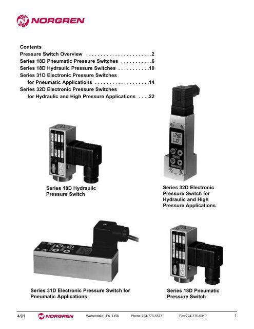
<strong>Contents</strong><br />
<strong>Pressure</strong> <strong>Switch</strong> <strong>Overview</strong> . . . . . . . . . . . . . . . . . . . . . . <strong>.2</strong><br />
Series 18D Pneumatic <strong>Pressure</strong> <strong>Switch</strong>es . . . . . . . . . . .6<br />
Series 18D Hydraulic <strong>Pressure</strong> <strong>Switch</strong>es . . . . . . . . . . .10<br />
Series 31D Electronic <strong>Pressure</strong> <strong>Switch</strong>es<br />
for Pneumatic Applications . . . . . . . . . . . . . . . . . . .14<br />
Series 32D Electronic <strong>Pressure</strong> <strong>Switch</strong>es<br />
for Hydraulic and High <strong>Pressure</strong> Applications . . . <strong>.2</strong>2<br />
Series 18D Hydraulic<br />
<strong>Pressure</strong> <strong>Switch</strong><br />
Series 32D Electronic<br />
<strong>Pressure</strong> <strong>Switch</strong> for<br />
Hydraulic and High<br />
<strong>Pressure</strong> Applications<br />
Series 31D Electronic <strong>Pressure</strong> <strong>Switch</strong> for<br />
Pneumatic Applications<br />
Series 18D Pneumatic<br />
<strong>Pressure</strong> <strong>Switch</strong><br />
4/01 Warrendale, PA USA Phone 724-776-5577 Fax 724-776-0310 1
<strong>Pressure</strong> <strong>Switch</strong>es<br />
Guaranteed Quality<br />
Norgren and Herion have joined<br />
forces to create one of the largest<br />
manufacturers of pressure control<br />
instruments in the world.<br />
Herion is the international market leader<br />
in high technology pressure switches<br />
with a comprehensive range of<br />
electronic and electrical products for<br />
the most demanding applications.<br />
The combination of Herion’s technical<br />
expertise and Norgren’s Global strength<br />
makes the perfect fit, bringing benefits to<br />
customers worldwide.<br />
Pneumatics/Vacuum<br />
Norgren Herion pressure switches provide:<br />
• Safe operation<br />
• Long life<br />
• Cost efficiency<br />
• Easy handling<br />
• Compact design<br />
• <strong>Switch</strong>ing pressure ranges<br />
vacuum to 435 psi (30 bar)<br />
•<br />
Electro-mechanical and<br />
electronic models<br />
Hydraulics<br />
• <strong>Switch</strong>ing pressure ranges<br />
0 to 10,000 psi (700 bar)<br />
•<br />
Electro-mechanical and<br />
electronic models<br />
2<br />
Warrendale, PA USA Phone 724-776-5577 Fax 724-776-0310 4/01
Rugged Designs<br />
<strong>Pressure</strong> <strong>Switch</strong>es<br />
Look inside our Model 18D pressure switch<br />
Convenient setpoint adjustment with locking screw<br />
Anodized aluminum housing<br />
machined from barstock<br />
<strong>Pressure</strong> transmission<br />
O-ring for environmental<br />
protection of adjustment<br />
mechanism<br />
Elastomer diaphragm<br />
supported by<br />
steel piston head<br />
(pneumatic versions)<br />
Heavy-duty range spring<br />
5 amp microswitch with<br />
gold plated contacts.<br />
UL & CSA approved<br />
Plug-in electrical<br />
connections<br />
DIN 43650<br />
Positive stop limits<br />
for overpressure<br />
Choice of pressure port thread options<br />
(port is stainless steel on hydraulic versions)<br />
<strong>Pressure</strong> switch applications and industries<br />
● Vacuum handling and transfer equipment<br />
● Packaging and production machines<br />
● Automated test stands<br />
● Hydraulic power units<br />
● Machine tools<br />
4/01 Warrendale, PA USA Phone 724-776-5577 Fax 724-776-0310 3
<strong>Pressure</strong> <strong>Switch</strong>es<br />
Pneumatics/Vacuum<br />
18D<br />
Competitively priced switches<br />
for pneumatic applications<br />
• Rugged, compact design<br />
•<br />
• Convenient setpoint adjustment<br />
• Plug-in electrical connections<br />
• UL and CSA approved microswitch<br />
Port options: 1/4" NPT, G 1/4, or flange mount<br />
<strong>Pressure</strong> range selection<br />
-14 to 0 psi (-1 to 0 bar)<br />
3 to 30 psi (<strong>.2</strong> to 2 bar)<br />
7 to 120 psi (.5 to 8 bar)<br />
15 to 230 psi (1 to 16 bar)<br />
15 to 435 psi (1 to 30 bar)<br />
31D<br />
The “Intelligent” choice for<br />
pneumatic pressure monitoring<br />
• Solid state technology<br />
•<br />
•<br />
•<br />
•<br />
Real-time LCD display of actual pressure<br />
Extremely long cycle life – up to 100 million cycles<br />
Adjustable hysteresis and window mode capability<br />
Can be calibrated without applied pressure<br />
<strong>Pressure</strong> range selection<br />
-14 to 15 psi (-1 to 1 bar)<br />
0 to 150 psi (0 to 10 bar)<br />
0 to 360 psi (0 to 25 bar)<br />
4<br />
Warrendale, PA USA Phone 724-776-5577 Fax 724-776-0310 4/01
Hydraulics<br />
18D<br />
<strong>Pressure</strong> <strong>Switch</strong>es<br />
Cost effective hydraulic<br />
pressure switches<br />
• Rugged, compact design<br />
•<br />
Port options: 1/4" NPT, 7/16-20 UNF, G 1/4,<br />
or flange mount<br />
• Convenient setpoint adjustment<br />
• Plug-in electrical connections<br />
•<br />
UL and CSA approved microswitch<br />
<strong>Pressure</strong> range selection<br />
70 to 1015 psi (5 to 70 bar)<br />
150 to 2320 psi (10 to 160 bar)<br />
360 to 3600 psi (25 to 250 bar)<br />
580 to 6100 psi (40 to 250 bar)<br />
32D<br />
Advanced solid state features –<br />
rugged industrial performance<br />
•<br />
•<br />
•<br />
•<br />
•<br />
Extremely long cycle life – up to 100 million cycles<br />
Real-time LCD display of actual pressure<br />
Adjustable hysteresis and window mode capability<br />
Can be calibrated without applied pressure<br />
Optional 4-20 mA and 0-10V analog output<br />
<strong>Pressure</strong> range selection<br />
0 to 100 bar<br />
0 to 160 bar<br />
0 to 250 bar<br />
0 to 350 bar<br />
0 to 700 bar<br />
4/01 Warrendale, PA USA Phone 724-776-5577 Fax 724-776-0310 5
Series 18D<br />
Pneumatic <strong>Pressure</strong> <strong>Switch</strong>es<br />
● Rugged compact design<br />
● Convenient setpoint adjustment<br />
● High cycle life<br />
● Vibration resistant to 15g<br />
● Microswitch approved by UL and CSA<br />
● Gold plated contacts – suitable for use in<br />
intrinsically safe circuits<br />
● Plug-in electrical connections<br />
Technical Data<br />
Fluid:<br />
Neutral gasses and light oil<br />
Construction:<br />
Diaphragm Actuated<br />
Port Size:<br />
1/4 NPT, G1/4 (BSPP), Flange<br />
Adjustment Range:<br />
28" Hg to 435 psi (-1 to 30 bar)<br />
Ambient Temperature:<br />
14° to 175°F (-10° to 80°C)<br />
Maximum Viscosity:<br />
450 SSU (1000 mm 2 /s)<br />
Fluid Temperature:<br />
-4° to 175°F (-20° to 80°C)<br />
Maximum <strong>Switch</strong>ing Rate:<br />
100 cycles/min<br />
Repeatability:<br />
± 3%, for vacuum ± 4%<br />
Electrical Connection:<br />
DIN 43650 Table A<br />
<strong>Switch</strong>ing Element:<br />
Microswitch<br />
Environmental Protection:<br />
IP65<br />
Mounting:<br />
Arbitrary<br />
Weight:<br />
.4 lbs (0<strong>.2</strong> kg)<br />
Graphic Symbol<br />
<strong>Switch</strong>ing function: Microswitch SPDT<br />
Terminals 1 - 3: Contacts close on rising pressure.<br />
Terminals 1 - 2: Contacts open on rising pressure.<br />
p<br />
2 3<br />
1<br />
6<br />
Warrendale, PA USA Phone 724-776-5577 Fax 724-776-0310 4/01
Series 18D Pneumatic <strong>Pressure</strong> <strong>Switch</strong>es<br />
General Information<br />
(Part numbers include mating connector)<br />
Part Number <strong>Pressure</strong> Range <strong>Switch</strong>ing <strong>Pressure</strong> Maximum Materials Fluid Connection Dimension<br />
psi (bar) Difference (Hysteresis)* Over <strong>Pressure</strong> ** Drawing No.<br />
psi (bar)<br />
psi (bar)<br />
Lower Upper Housing Seal Type Size<br />
Range Range Dyn./Static<br />
0880100 -14 – 0 (-1 – 0) 2 (0.15) 3 (0.18) 1150 (80) Al FKM/NBR Female G1/4 01<br />
0880120 -14 – 0 (-1 – 0) 2 (0.15) 3 (0.18) 1150 (80) Al FKM/NBR Female 1/4 NPT 01<br />
0881100 -14 – 0 (-1 – 0) 2 (0.15) 3 (0.18) 1150 (80) Al FKM/NBR Flange - 03<br />
0880200 3 – 30 (0<strong>.2</strong> – 2) 2 (0.15) 4 (0<strong>.2</strong>7) 1150 (80) Al FKM/NBR Female G1/4 01<br />
0880220 3 – 30 (0<strong>.2</strong> – 2) 2 (0.15) 4 (0<strong>.2</strong>7) 1150 (80) Al FKM/NBR Female 1/4 NPT 01<br />
0881200 3 – 30 (0<strong>.2</strong> – 2) 2 (0.15) 4 (0<strong>.2</strong>7) 1150 (80) Al NBR/NBR Flange - 03<br />
0880300 7 – 120 (0.5 – 8) 4 (0<strong>.2</strong>5) 9 (0.65) 1150 (80) Al NBR/NBR Female G1/4 02<br />
0880320 7 – 120 (0.5 – 8) 4 (0<strong>.2</strong>5) 9 (0.65) 1150 (80) Al NBR/NBR Female 1/4 NPT 02<br />
0881300 7 – 120 (0.5 – 8) 4 (0<strong>.2</strong>5) 9 (0.65) 1150 (80) Al NBR/NBR Flange - 04<br />
0880400 15 – 230 (1 – 16) 4 (0.30) 13 (0.90) 1150 (80) Al NBR/NBR Female G1/4 02<br />
0880420 15 – 230 (1 – 16) 4 (0.30) 13 (0.90) 1150 (80) Al NBR/NBR Female 1/4 NPT 02<br />
0881400 15 – 230 (1 – 16) 4 (0.30) 13 (0.90) 1150 (80) Al NBR/NBR Flange - 04<br />
0880600 15 – 435 (1 – 30) 15 (1.0) 73 (5.00) 1150 (80) Al NBR/NBR Female G1/4 02<br />
0880620 15 – 435 (1 – 30) 15 (1.0) 73 (5.00) 1150 (80) Al NBR/NBR Female 1/4 NPT 02<br />
* <strong>Switch</strong>ing pressure difference (hysteresis) is not<br />
adjustable. Maximum values are shown.<br />
** Do not subject switch to maximum allowable<br />
pressure during normal operation. Even short<br />
pressure peaks must not exceed this value.<br />
Materials:<br />
Al = Aluminum<br />
NBR = Buna N<br />
FKM = Viton<br />
Making And/Or Breaking Capacity<br />
Load Level* Type of Current Type of Load Vmin [V] Maximum Permanent Current Imax [A] at V Contact life<br />
24 V 125 V 250 V electrical mechanical<br />
at I max at I ≈ 0<br />
Standard<br />
AC Resistive 12 5 5 5<br />
5 x 10 4 approx 10 7<br />
(relays, switching switching<br />
solenoids)<br />
AC<br />
Inductive<br />
PF ≈ 0.7<br />
12 3 3 3<br />
cycles cycles<br />
DC Resistive 12 5 .4 -<br />
DC Inductive 12 3 .05 -<br />
L/R ≈ 10 ms<br />
Low<br />
AC Resistive 5 .34 .08 .04<br />
2 x 10 5 approx 10 7<br />
(electronic switching switching<br />
circuits)<br />
DC Inductive 5 .1 - -<br />
cycles cycles<br />
L/R ≈ 10 ms<br />
* Load Level Explanation<br />
Series 18D <strong>Pressure</strong> <strong>Switch</strong>es have microswitch contacts with<br />
gold-plating over silver base metal. The gold plating remains<br />
intact when “low level” voltage / current levels are observed.<br />
This feature assures highly reliable switching in low-level<br />
electronic circuits.<br />
Standard applications do not require the gold plating which will<br />
decay naturally when switching larger electrical loads.<br />
Notes:<br />
1. Reference conditions:<br />
30 cycles per min and 86°F (30°C) ambient.<br />
2. Reducing load current to 50% of I max approximately<br />
doubles contact life.<br />
3. Creepage and clearance distances correspond to insulation<br />
group B per VDE Reg. 0110 (except contact clearance of<br />
microswitch.<br />
4/01 Warrendale, PA USA Phone 724-776-5577 Fax 724-776-0310 7
Series 18D Pneumatic <strong>Pressure</strong> <strong>Switch</strong>es<br />
All Dimensions in Inches (mm)<br />
Dimensional drawing 01<br />
Dimensional drawing 02<br />
<strong>Switch</strong> Adjustment<br />
<strong>Switch</strong> Adjustment<br />
1.18 (30)<br />
2.95 (75)<br />
1.18 (30)<br />
2.95 (75)<br />
.79 (20)<br />
1.18 (30)<br />
.79 (20)<br />
1.18 (30)<br />
.59 (15)<br />
<strong>.2</strong>1 (5.3)<br />
.61<br />
(15.5)<br />
2.83 (72)<br />
.59 (15)<br />
<strong>.2</strong>1 (5.3)<br />
.37<br />
(9.5) 2.83 (72)<br />
1<br />
/4 NPT or G 1 /4<br />
1<br />
/4 NPT or G 1 /4<br />
Dimensional drawing 03 (flange mount)<br />
Dimensional drawing 04 (flange mount)<br />
<strong>Switch</strong> Adjustment<br />
<strong>Switch</strong> Adjustment<br />
1.18 (30)<br />
.79 (20)<br />
1.18 (30)<br />
2.95 (75)<br />
1.18 (30)<br />
.79 (20)<br />
1.18 (30)<br />
2.95 (75)<br />
<strong>.2</strong>1 (5.3)<br />
2.83 (72)<br />
<strong>.2</strong>1 (5.3)<br />
.59 (15)<br />
2.83 (72)<br />
.315 (8) dia recess<br />
at pressure inlet for<br />
O-ring. (O-ring supplied<br />
with switch)<br />
.59 (15)<br />
.315 (8) dia recess<br />
at pressure inlet for<br />
O-ring. (O-ring supplied<br />
with switch)<br />
Protective Cover<br />
An optional elastomer cover for protection of the switch<br />
adjustment against dirt and splashing liquids<br />
1.18 (30)<br />
<strong>.2</strong>8 (7)<br />
1.18 (30)<br />
.06 (1.5)<br />
Part No. 0554737<br />
8<br />
Warrendale, PA USA Phone 724-776-5577 Fax 724-776-0310 4/01
Series 18D Pneumatic <strong>Pressure</strong> <strong>Switch</strong>es<br />
<strong>Switch</strong> Selection and Mounting Instructions<br />
• Select a switch such that the desired switching point<br />
falls roughly in the middle of the adjustment range.<br />
• Do not exceed switch electrical ratings. Use an<br />
appropriately sized relay when switching larger<br />
electrical loads.<br />
• For liquid media with pressure spikes and/or<br />
pulsating pressures, install a pressure snubber.<br />
• For outdoor applications, sufficient protection must<br />
be provided.<br />
Adjustment of <strong>Switch</strong>ing Point<br />
Either the upper or the lower switching point may be<br />
adjusted. The opposite one is then fixed by the<br />
hysteresis characteristics of the switch.<br />
Use a pressure gauge for exact adjustment. Proceed<br />
as follows:<br />
1.Loosen locking screw.<br />
2.Adjust the switching point using a 5 mm hexagon<br />
wrench. Clockwise rotation increases switching<br />
pressure and counter-clockwise rotation decreases<br />
switching pressure.<br />
Low-end of adjustment range is reached when top of<br />
adjustment barrel is approximately level with top of<br />
switch housing. High-end of adjustment range is<br />
reached when adjustment barrel is fully CW.<br />
3.Re-tighten locking screw.<br />
Adjustment Of <strong>Switch</strong>ing Points<br />
Locking Screw<br />
4/01 Warrendale, PA USA Phone 724-776-5577 Fax 724-776-0310 9
Series 18D<br />
Hydraulic <strong>Pressure</strong> <strong>Switch</strong>es<br />
● Rugged compact design<br />
● Convenient setpoint adjustment<br />
● High cycle life<br />
● Vibration resistant to 15g<br />
● Microswitch approved by UL and CSA<br />
● Gold plated contacts - suitable for use in<br />
intrinsically safe circuits<br />
● Plug-in electrical connections<br />
Technical Data<br />
Fluid:<br />
Hydraulic, lubricating and light fuel oils<br />
Construction:<br />
Piston actuated<br />
Port Size:<br />
1/4 NPT, 7/16-20 UNF (SAE-4), G1/4 (BSPP), Flange<br />
Adjustment range:<br />
70 – 6100 psi (5 - 420 bar)<br />
Ambient Temperature:<br />
-13° to 175°F (-25° to 80°C )<br />
Maximum Viscosity:<br />
450 SSU (1000 mm 2 /s)<br />
Fluid Temperature:<br />
-13° to 175°F (-25° to 80°C )<br />
Maximum <strong>Switch</strong>ing Rate:<br />
100 cycles/min<br />
Repeatability:<br />
± 3%<br />
Electrical Connection:<br />
DIN 43650 Table A<br />
<strong>Switch</strong>ing Element:<br />
Microswitch<br />
Environmental Protection:<br />
IP65<br />
Mounting:<br />
Arbitrary<br />
Weight:<br />
.4 lbs (0<strong>.2</strong> kg)<br />
Graphic Symbol<br />
<strong>Switch</strong>ing function: Microswitch SPDT<br />
Terminals 1 - 3: Contacts close on rising pressure.<br />
Terminals 1 - 2: Contacts open on rising pressure.<br />
p<br />
2 3<br />
1<br />
10<br />
Warrendale, PA USA Phone 724-776-5577 Fax 724-776-0310 4/01
General Information<br />
(Part numbers include mating connector)<br />
Series 18D Hydraulic <strong>Pressure</strong> <strong>Switch</strong>es<br />
Part Number <strong>Pressure</strong> Range <strong>Switch</strong>ing <strong>Pressure</strong> Maximum Materials Fluid Connection Dimension<br />
psi (bar) Difference (Hysteresis)* Over <strong>Pressure</strong> ** Drawing No.<br />
psi (bar)<br />
psi (bar)<br />
Lower Upper Housing/ Seal Type Size<br />
Range Range Piston Dyn./Static<br />
0882100 70 – 1015 (5 – 70) 152 (10.5) 218 (15) 5800 (400) Al/Steel PTFE/NBR Female G1/4 01<br />
0883100 70 – 1015 (5 – 70) 152 (10.5) 218 (15) 5800 (400) Al/Steel PTFE/NBR Flange - 02<br />
0882119 70 – 1015 (5 – 70) 152 (10.5) 218 (15) 5800 (400) Al/Steel PTFE/NBR Female 7/16-20 UNF 01<br />
0882120 70 – 1015 (5 – 70) 152 (10.5) 218 (15) 5800 (400) Al/Steel PTFE/NBR Female 1/4 NPT 01<br />
0882200 150 – 2320 (10 – 160) 160 (11) 247 (17) 5800 (400) Al/Steel PTFE/NBR Female G1/4 01<br />
0883200 150 – 2320 (10 – 160) 160 (11) 247 (17) 5800 (400) Al/Steel PTFE/NBR Flange - 02<br />
0882219 150 – 2320 (10 – 160) 160 (11) 247 (17) 5800 (400) Al/Steel PTFE/NBR Female 7/16-20 UNF 01<br />
0882220 150 – 2320 (10 – 160) 160 (11) 247 (17) 5800 (400) Al/Steel PTFE/NBR Female 1/4 NPT 01<br />
0882300 360 – 3600 (25 – 250) 160 (11) 247 (17) 5800 (400) Al/Steel PTFE/NBR Female G1/4 01<br />
0883300 360 – 3600 (25 – 250) 160 (11) 247 (17) 5800 (400) Al/Steel PTFE/NBR Flange - 02<br />
0882319 360 – 3600 (25 – 250) 160 (11) 247 (17) 5800 (400) Al/Steel PTFE/NBR Female 7/16-20 UNF 01<br />
0882320 360 – 3600 (25 – 250) 160 (11) 247 (17) 5800 (400) Al/Steel PTFE/NBR Female 1/4 NPT 01<br />
0882400 580 – 6100 (40 – 420) 247 (17) 508 (35) 8700 (600) Al/Steel PTFE/NBR Female G1/4 01<br />
0883400 580 – 6100 (40 – 420) 247 (17) 508 (35) 8700 (600) Al/Steel PTFE/NBR Flange - 02<br />
0882419 580 – 6100 (40 – 420) 247 (17) 508 (35) 8700 (600) Al/Steel PTFE/NBR Female 7/16-20 UNF 01<br />
0882420 580 – 6100 (40 – 420) 247 (17) 508 (35) 8700 (600) Al/Steel PTFE/NBR Female 1/4 NPT 01<br />
* <strong>Switch</strong>ing pressure difference (hysteresis) is not<br />
adjustable. Maximum values are shown.<br />
** Do not subject switch to maximum allowable<br />
pressure during normal operation. Even short<br />
pressure peaks must not exceed this value.<br />
Materials:<br />
Al = Aluminum<br />
NBR = Buna N<br />
PTFE = Teflon<br />
Making And/Or Breaking Capacity<br />
Load Level* Type of Current Type of Load Vmin [V] Maximum Permanent Current Imax [A] at V Contact life<br />
24 V 125 V 250 V electrical mechanical<br />
at I max at I ≈ 0<br />
Standard<br />
AC Resistive 12 5 5 5<br />
5 x 10 4 approx 10 7<br />
(relays, switching switching<br />
solenoids)<br />
AC<br />
Inductive<br />
PF ≈ .7<br />
12 3 3 3<br />
cycles cycles<br />
DC Resistive 12 5 .4 -<br />
DC Inductive 12 3 .05 -<br />
L/R ≈ 10 ms<br />
Low<br />
AC Resistive 5 .34 .08 .04<br />
2 x 10 5 approx 10 7<br />
(electronic switching switching<br />
circuits)<br />
DC Inductive 5 .1 - -<br />
cycles cycles<br />
L/R ≈ 10 ms<br />
* Load Level Explanation<br />
Series 18D <strong>Pressure</strong> <strong>Switch</strong>es have microswitch contacts with<br />
gold-plating over silver base metal. The gold plating remains<br />
intact when “low level” voltage / current levels are observed.<br />
This feature assures highly reliable switching in low-level<br />
electronic circuits.<br />
Standard applications do not require the gold plating – which<br />
will decay naturally when switching larger electrical loads.<br />
Notes:<br />
1. Reference conditions:<br />
30 cycles per min and 86°F (30°C) ambient.<br />
2. Reducing load current to 50% of I max approximately<br />
doubles contact life.<br />
3. Creepage and clearance distances correspond to insulation<br />
group B per VDE Reg. 0110 (except contact clearance of<br />
microswitch.<br />
4/01 Warrendale, PA USA Phone 724-776-5577 Fax 724-776-0310 11
Series 18D Hydraulic <strong>Pressure</strong> <strong>Switch</strong>es<br />
All Dimensions in Inches (mm)<br />
Dimensional drawing 01<br />
Dimensional drawing 02 (flange mount)<br />
1.18 (30)<br />
.79 (20)<br />
1.18 (30)<br />
2.95 (75)<br />
<strong>Switch</strong> Adjustment<br />
1.18 (30)<br />
.79 (20)<br />
1.18 (30)<br />
2.95 (75)<br />
<strong>Switch</strong> Adjustment<br />
.59 (15)<br />
<strong>.2</strong>1 (5.3)<br />
.31<br />
(8) 2.83 (72)<br />
<strong>Pressure</strong> port<br />
material:<br />
430 SS (1.4104)<br />
1<br />
/4 NPT, G 1 /4 or<br />
7/16-20 UNF<br />
.59 (15)<br />
<strong>.2</strong>1 (5.3)<br />
2.83 (72)<br />
.315 (8) dia recess<br />
at pressure inlet for<br />
O-ring. (O-ring supplied<br />
with switch)<br />
Protective Cover<br />
An optional elastomer cover for protection of the switch<br />
adjustment against dirt and splashing liquids<br />
1.18 (30)<br />
<strong>.2</strong>8 (7)<br />
1.18 (30)<br />
.06 (1.5)<br />
Part No. 0554737<br />
12<br />
Warrendale, PA USA Phone 724-776-5577 Fax 724-776-0310 4/01
Series 18D Hydraulic <strong>Pressure</strong> <strong>Switch</strong>es<br />
<strong>Switch</strong> Selection and Mounting Instructions<br />
• Select a switch such that the desired switching point<br />
falls roughly in the middle of the adjustment range.<br />
• Do not exceed switch electrical ratings. Use an<br />
appropriately sized relay when switching larger<br />
electrical loads.<br />
• For liquid media with pressure spikes and/or<br />
pulsating pressures, install a pressure snubber.<br />
• For outdoor applications, sufficient protection must<br />
be provided.<br />
Adjustment of <strong>Switch</strong>ing Point<br />
Either the upper or the lower switching point may be<br />
adjusted. The opposite one is then fixed by the<br />
hysteresis characteristics of the switch.<br />
Use a pressure gauge for exact adjustment. Proceed<br />
as follows:<br />
1.Loosen locking screw.<br />
2.Adjust the switching point using a 5 mm hexagon<br />
wrench. Clockwise rotation increases switching<br />
pressure and counter-clockwise rotation decreases<br />
switching pressure.<br />
Low-end of adjustment range is reached when top of<br />
adjustment barrel is approximately level with top of<br />
switch housing. High-end of adjustment range is<br />
reached when adjustment barrel is fully CW.<br />
3.Re-tighten locking screw.<br />
Adjustment Of <strong>Switch</strong>ing Points<br />
Locking Screw<br />
4/01 Warrendale, PA USA Phone 724-776-5577 Fax 724-776-0310 13
●<br />
●<br />
●<br />
●<br />
●<br />
●<br />
●<br />
Digital Display Panel<br />
– Real-time display of actual pressure<br />
– LED status indication<br />
Adjustable Hysteresis<br />
– Independent setting of switching and reset pressures<br />
Window Mode Capability<br />
Off-line Calibration<br />
– <strong>Switch</strong>ing points can be preset without applied<br />
pressure<br />
Extremely Long Service Life<br />
– No moving parts, no mechanical contacts<br />
– Up to 100 million cycles<br />
Fast Accurate Response<br />
– 5ms switching time<br />
– .5% full scale linearity<br />
Full 1 Amp <strong>Switch</strong>ing Capability<br />
– “Normally on” or “Normally off” operation<br />
Series 31D<br />
Electronic <strong>Pressure</strong> <strong>Switch</strong>es<br />
for Pneumatic Applications<br />
Technical Data<br />
Fluid:<br />
Filtered compressed air, lubricated or unlubricated<br />
Fluid Connection:<br />
Female 1/4 NPT, G 1/4<br />
Mounting:<br />
Arbitrary<br />
Electrical Connection:<br />
DIN 43650 Table A plug-in<br />
Adjustment Range:<br />
-14 to 350 psi (-1 to 25 bar)<br />
Ambient Temperature:<br />
14° to 140°F (-10° to 60°C)<br />
Fluid Temperature:<br />
14° to 175°F (-10° to 80°C)<br />
Temperature sensitivity (zero point):<br />
0.4% of FS value/10 K<br />
Temperature sensitivity (range):<br />
0<strong>.2</strong>% of FS value/10 K<br />
<strong>Switch</strong>ing point:<br />
Adjustable between 0 and 100% of FS value<br />
Reset point:<br />
Adjustable between 0 and 100% of FS value<br />
Display format:<br />
3-1/2 digit LCD<br />
Linearity:<br />
< 0.5% of FS value<br />
Environmental Protection<br />
IP65<br />
Housing Material:<br />
Die-cast zinc<br />
Series 31D pressure switches are electronic<br />
devices for pressure monitoring. The switches<br />
consist essentially of a integral pressure<br />
sensor, microprocessor evaluation circuitry, and<br />
a solid state output driver.<br />
14<br />
Warrendale, PA USA Phone 724-776-5577 Fax 724-776-0310 4/01
Series 31D <strong>Pressure</strong> <strong>Switch</strong>es<br />
General Information<br />
(Part numbers include mating connector)<br />
<strong>Pressure</strong> display in PSI<br />
Part No. <strong>Switch</strong>ing <strong>Pressure</strong> Maximum Fluid Type of Step Size<br />
Range (psi) <strong>Pressure</strong> (psi) Connection Fluid Connection of Display (psi)<br />
0886120 -14 – 15 150 1/4 NPT Female .14<br />
0886620 0 – 150 440 1/4 NPT Female .6 - .7<br />
0886720 0 – 350 580 1/4 NPT Female 1 - 2<br />
<strong>Pressure</strong> display in Bar<br />
Part No. <strong>Switch</strong>ing <strong>Pressure</strong> Maximum Fluid Type of Step Size<br />
Range (bar) <strong>Pressure</strong> (bar) Connection Fluid Connection of Display (bar)<br />
0886100 -1 – 1 10 G1/4 Female .01<br />
0886600 0 – 10 30 G1/4 Female .04 - .05<br />
0886700 0 – 25 40 G1/4 Female .1<br />
4/01 Warrendale, PA USA Phone 724-776-5577 Fax 724-776-0310 15
Series 31D <strong>Pressure</strong> <strong>Switch</strong>es<br />
All Dimensions in Inches (mm)<br />
Electrical Parameters<br />
Electrical connection<br />
DIN 43650 Table A<br />
Power supply (polarity safe) 18 to 32V dc<br />
Permissible residual ripple 10% (within 18 to 32V)<br />
Current consumption<br />
RP**<br />
Signal “on” with falling pressure, if SP < RP<br />
1.97 (50)<br />
1.85 (47) 1.18 (30)<br />
NPT 1 /4<br />
G 1 /4<br />
* SP = <strong>Switch</strong>ing point<br />
**RP = Reset point<br />
Ø.31 (8)<br />
4.53 (115)<br />
.47<br />
(12)<br />
.59 (15)<br />
<strong>.2</strong>0 (5<strong>.2</strong>)<br />
.05 (1<strong>.2</strong>)<br />
.79 (20)<br />
1.18 (30)<br />
16<br />
Warrendale, PA USA Phone 724-776-5577 Fax 724-776-0310 4/01
Series 31D <strong>Pressure</strong> <strong>Switch</strong>es<br />
Adjusting the <strong>Switch</strong>ing Points (SP) and<br />
Reset Points (RP)<br />
a) Adjusting the switching point.<br />
Case 1 or Case 2<br />
Q<br />
Press and hold the SP button. The display will show the<br />
previous switching pressure setting, and the dotted bar<br />
will flash while the button is pressed down (case 1).<br />
You can now use the cursor keys to adjust the switching<br />
point upwards or downwards. If a cursor key is held<br />
down, the values will change faster. When the cursor<br />
key is released again, the switch-on pressure setting will<br />
cease to change. This setting is stored and activated<br />
when the SP button is released, after which the display<br />
will show the current pressure value and the bar will quit<br />
flashing.<br />
b) Adjusting the reset point.<br />
Case 3 or Case 4<br />
p<br />
Q<br />
p<br />
c) Setting a buffering time.<br />
In order to prevent brief pressure “spikes” or “surges”<br />
from causing undesired switching, a buffering time can<br />
be entered. The effect of this is that pressure changes<br />
are evaluated only if the pressure signal in question is<br />
present for longer than the buffering time. In order to set<br />
a buffering time, press the button SP before the power<br />
supply is switched on. Release this button again after<br />
the power supply has been switched on. The display will<br />
then show the buffering time in milliseconds (e.g. 03) or<br />
seconds. The cursor buttons ▼, ▲ can be used to set<br />
the buffering time to 03, 06,12, 24. When this has been<br />
done, press SP to store the setting.<br />
d) Setting the pressure switch to ambient<br />
pressure = 0.<br />
Since ambient pressure varies according to altitude, the<br />
user may re-calibrate the zero point to match local<br />
conditions.<br />
Press the button RP before the power supply is<br />
switched on. Release this button again after the power<br />
supply has been switched on and the display test has<br />
run. The display will then show "OFS". The cursor<br />
buttons ▼, ▲ can be used to set the pressure display to<br />
0. When this has been done, press SP to store the<br />
setting.<br />
Q<br />
Q<br />
p<br />
p<br />
Press and hold the RP button. The display will show the<br />
previous reset pressure setting, and the dotted bar will<br />
flash while the button is pressed down.<br />
You can now use the cursor keys to adjust the reset<br />
point in the same manner as described above.<br />
During both adjustment operations, it may occur that the<br />
hysteresis graph changes from one state to another at<br />
the time a transition is made through the point<br />
"<strong>Switch</strong>ing pressure = Reset pressure". When both<br />
points are correctly set, the hysteresis graph will also be<br />
correct. You can change between SP and RP as often<br />
as you wish until the settings are correct.<br />
4/01 Warrendale, PA USA Phone 724-776-5577 Fax 724-776-0310 17
Series 31D <strong>Pressure</strong> <strong>Switch</strong>es<br />
e) Hysteresis mode<br />
If it is desired to operate with a fixed hysteresis value<br />
instead of the reset point, this value can be selected as<br />
desired.<br />
In order to set a hysteresis value, the two buttons SP<br />
and ▼ must be pressed simultaneously before the<br />
power supply is switched on.<br />
Release these buttons again after the power supply has<br />
been switched on and the display test has run. The<br />
display will then show the operating mode. The cursor<br />
buttons ▲,▼ can now be used to change the operating<br />
mode until "HYS" appears in the display. When this has<br />
been done, press SP to store the setting.<br />
The SP button can be used to display the switchingpoint<br />
setting, which can be modified by means of the<br />
cursor buttons ▲,▼.<br />
The button RP can be used to display the hysteresis<br />
setting, which can also be modified by means of the<br />
cursor buttons ▲,▼.<br />
Negative hysteresis means: Signal “on” with rising<br />
pressure (case 1).<br />
Positive hysteresis means: Signal “on” with falling<br />
pressure (case 2).<br />
If the switching point is modified, this will automatically<br />
also result in a change in the reset point by a value<br />
equal to the hysteresis setting.<br />
Case 1<br />
1<br />
Negative hysteresis<br />
Release these buttons again after the power supply has<br />
been switched on and the display test has run. The<br />
display will then show the operating mode.<br />
The cursor buttons ▲,▼. can now be used to change<br />
the operating mode until "FEn" (standing for "Window")<br />
in the display. When this has been done, press SP to<br />
store the setting. The button SP can be used to display<br />
the switching-point setting, which can be modified by<br />
means of the cursor buttons ▼, ▲.<br />
The distance between the switching point and reset<br />
point is the switching window. If the switching point is<br />
lower than the reset point, a signal will be output as long<br />
as the pressure lies within the preset window (case 1,<br />
rising pressure). If the switching point is higher than the<br />
reset point, a signal will be output as long as the<br />
pressure lies outside the preset window (case 2, rising<br />
pressure). In the case of falling pressure, the signal is<br />
inverted.<br />
Case 1<br />
1<br />
0<br />
Case 2<br />
1<br />
On = <strong>Pressure</strong> within window<br />
SP < RP<br />
Off = <strong>Pressure</strong> within window<br />
p<br />
<strong>Switch</strong>ing point<br />
0<br />
p<br />
Case 2<br />
Positive hysteresis<br />
1<br />
0<br />
RP < SP p<br />
<strong>Switch</strong>ing point<br />
0<br />
f) Window mode<br />
p<br />
Std = Standard mode, switching and reset points adjustable<br />
HYS = Hysteresis mode, switching point and hysteresis<br />
adjustable<br />
FEn = Window mode, switching window adjustable<br />
If it is desired to monitor whether the pressure lies within<br />
a certain range, a switching window can be created for<br />
this purpose. The pressure switch will then indicate<br />
cases in which the actual pressure lies above or below<br />
this area. In order to set a switching window, the two<br />
buttons SP and ▼ must be pressed simultaneously<br />
before the power supply is switched on.<br />
18<br />
Warrendale, PA USA Phone 724-776-5577 Fax 724-776-0310 4/01
<strong>Switch</strong>ing Characteristic Graphs<br />
Signal “on” with rising pressure<br />
Setting SP* > RP**<br />
Series 31D <strong>Pressure</strong> <strong>Switch</strong>es<br />
Signal “on” with falling pressure<br />
Setting SP < RP<br />
p<br />
SP<br />
p<br />
RP<br />
RP<br />
SP<br />
t<br />
t<br />
UA<br />
U<br />
Signal “off” with rising pressure<br />
Setting RP > SP<br />
p<br />
RP<br />
t<br />
Signal “off” with falling pressure<br />
Setting RP < SP<br />
p<br />
SP<br />
t<br />
SP<br />
RP<br />
t<br />
t<br />
U<br />
UA<br />
t<br />
Explanation:<br />
When the switching point (SP) is adjusted HIGHER than the reset point (RP), then the switching output will be “normally off”.<br />
When the switching point (SP) is adjusted LOWER than the reset point (RP), then the switching output will be “normally on”.<br />
Position of operating elements<br />
t<br />
* SP = <strong>Switch</strong>ing point<br />
**RP = Reset point<br />
<strong>Pressure</strong> display<br />
<strong>Switch</strong>ing<br />
function graph<br />
<strong>Switch</strong>ing point button<br />
<strong>Switch</strong>ing output LED<br />
Raise switching<br />
or reset point button<br />
Reset point button<br />
Lower switching<br />
or reset point button<br />
4/01 Warrendale, PA USA Phone 724-776-5577 Fax 724-776-0310 19
Series 31D <strong>Pressure</strong> <strong>Switch</strong>es<br />
Error messages<br />
Display of hardware errors or malfunctions<br />
Display Meaning Cause / Remedy<br />
O.Er Output error Error at switching output: Circuit-breaker defective, feedback loop to processor open circuit. Repair necessary.<br />
E.Er E 2 PROM error E 2 PROM module defective or connection to processor faulty. Repair necessary.<br />
I.Er Initialization error Checksum of initialization data incorrect. Remedy: Call up any SETUP function and acknowledge the setting with SP. This error message is caused by<br />
a data error. All setup values should therefore be checked and corrected if necessary .<br />
C.Er Calibration error Checksum of calibration data incorrect. Recalibration necessary.<br />
SC.L Short-circuit low Short-circuit between output and ground. Check wiring: Power supply may be too weak for connected load (leading to collapse of voltage, particularly<br />
with loads with a high switch-on current such as incandescent lamps or capacitances).<br />
UFL Underflow The applied pressure is below the measuring range:<br />
Increase pressure until it is within the measuring range.<br />
OFL Overflow The applied pressure is above the measuring range:<br />
Decrease pressure until it is within the measuring range.<br />
Display of hardware errors or malfunctions (can be switched off)<br />
Display Meaning Cause / Remedy<br />
SC.H Short-circuit high Short-circuit between output and power supply. Check wiring. If the switching line from the load (e.g. electrical control device, PLC or similar) is being<br />
held at an open-circuit potential of > 3V, or if several pressure switches are being operated in parallel, this function should be switched off.<br />
Disconnection: ▼ during display test, then adjust with ▼ or ▲<br />
U.Lo Voltage low Power supply voltage too low (
Norgren offers electronic solutions<br />
for your pneumatic circuit design.<br />
Electronic Media<br />
In addition to printed catalogs,<br />
Norgren offers a wide variety of<br />
valuable information at our<br />
web site.<br />
This is a great source for additional<br />
pneumatic product catalogs,<br />
CAD files, circuit design software,<br />
distributor locations, customer<br />
service and application<br />
engineering contacts.<br />
To access our website, set your<br />
web browser to:<br />
www.usa.norgren.com<br />
5400 South Delaware Street<br />
Littleton, Colorado 80120-1663<br />
Phone: 303-794-2611 Fax: 303-795-9487<br />
www.usa.norgren.com<br />
e-mail: inquiry@usa.norgren.com<br />
4/01 Warrendale, PA USA Phone 724-776-5577 Fax 724-776-0310 21
●<br />
●<br />
●<br />
●<br />
●<br />
●<br />
●<br />
●<br />
Digital Display Panel<br />
– Real-time display of actual pressure<br />
– LED status indication<br />
Adjustable Hysteresis<br />
– Independent setting of switching and reset pressures<br />
Window Mode Capability<br />
Off-line Calibration<br />
– <strong>Switch</strong>ing points can be preset without applied<br />
pressure<br />
Extremely Long Service Life<br />
– No moving parts, no mechanical contacts<br />
– Up to 100 million cycles<br />
Fast Accurate Response<br />
– 5ms switching time<br />
– .5% full scale linearity<br />
Full 1 Amp <strong>Switch</strong>ing Capability<br />
– “Normally on” or “Normally off” operation<br />
Optional Versions with Analog Output<br />
Series 32D<br />
Electronic <strong>Pressure</strong> <strong>Switch</strong>es for Hydraulic<br />
and High <strong>Pressure</strong> Applications<br />
Technical Data<br />
Fluid:<br />
Gaseous, liquid, aggressive and neutral fluids<br />
Fluid Connection:<br />
Flange (mount plates purchased separately)<br />
Mounting:<br />
Arbitrary<br />
Electrical Connection:<br />
Versions without analog output option have DIN 43650 Table A<br />
connector. Optional versions with analog output have DIN 43651 (7 pin)<br />
circular connector.<br />
Adjustment Range:<br />
0 to 700 bar<br />
Ambient Temperature:<br />
14° to 140°F (-10° to 60°C)<br />
Fluid Temperature:<br />
14° to 175°F (-10° to 80°C)<br />
Temperature sensitivity (zero point):<br />
0.4% of FS value/10 K<br />
Temperature sensitivity (range):<br />
0.3% of FS value/10 K<br />
<strong>Switch</strong>ing point:<br />
Adjustable between 0 and 100% of FS value<br />
Reset point:<br />
Adjustable between 0 and 100% of FS value<br />
Display format:<br />
3-1/2 digit LCD<br />
Linearity:<br />
Series 32D Electronic <strong>Pressure</strong> <strong>Switch</strong>es<br />
General Information<br />
(Part numbers include mounting screws, o-ring, and electrical mating connector)<br />
<strong>Pressure</strong> display in Bar<br />
Part No. <strong>Switch</strong>ing <strong>Pressure</strong> Proof/Burst Electrical Analog Output Step Size<br />
(bar) <strong>Pressure</strong> (bar) Connection 0–10V and 4–20mA of Display (bar)<br />
0875100 0 – 100 200/300 DIN 43650 0.5<br />
0875130 0 – 100 200/300 DIN 43651 x 0.5<br />
0875200 0 – 160 300/400 DIN 43650 0.8<br />
0875230 0 – 160 300/400 DIN 43651 x 0.8<br />
0875300 0 – 250 500/750 DIN 43650 1–2<br />
0875330 0 – 250 500/750 DIN 43651 x 1–2<br />
0875400 0 – 350 500/750 DIN 43650 1–2<br />
0875430 0 – 350 500/750 DIN 43651 x 1–2<br />
0875500 0 – 500 750/1000 DIN 43650 2–3<br />
0875530 0 – 500 750/1000 DIN 43651 x 2–3<br />
0875600 0 – 700 1000/1200 DIN 43650 3–4<br />
0875630 0 – 700 1000/1200 DIN 43651 x 3–4<br />
Notes:<br />
1) Mounting plates purchased separately see p. 27.<br />
2) For hydraulic applications with pressure spikes or surges install a pressure snubber.<br />
4/01 Warrendale, PA USA Phone 724-776-5577 Fax 724-776-0310 23
Series 32D Electronic <strong>Pressure</strong> <strong>Switch</strong>es<br />
Electrical parameters<br />
Electrical connection<br />
DIN 43650 Table A without analog output<br />
DIN 43651 (7 pin), with analog output<br />
Power supply (polarity safe) 18 to 32V dc<br />
Permissible residual ripple: 10% (within 18 to 32V)<br />
Current consumption:<br />
RP*<br />
Signal “on” with falling pressure, if SP < RP<br />
*SP = <strong>Switch</strong>ing point<br />
*RP = Reset point<br />
24<br />
Warrendale, PA USA Phone 724-776-5577 Fax 724-776-0310 4/01
Series 32D Electronic <strong>Pressure</strong> <strong>Switch</strong>es<br />
Adjusting the <strong>Switch</strong>ing Points (SP) and<br />
Reset Points (RP)<br />
a) Adjusting the switching point.<br />
Case 1 or Case 2<br />
Q<br />
Press and hold the SP button. The display will show the<br />
previous switching pressure setting, and the dotted bar<br />
will flash while the button is pressed down (case 1).<br />
You can now use the cursor keys to adjust the switching<br />
point upwards or downwards. If a cursor key is held<br />
down, the values will change faster. When the cursor key<br />
is released again, the switch-on pressure setting will<br />
cease to change. This setting is stored and activated<br />
when the SP button is released, after which the display<br />
will show the current pressure value and the bar will quit<br />
flashing.<br />
b) Adjusting the reset point.<br />
Case 3 or Case 4<br />
p<br />
Q<br />
p<br />
c) Setting a buffering time.<br />
In order to prevent brief pressure “spikes” or “surges”<br />
from causing undesired switching, a buffering time can<br />
be entered. The effect of this is that pressure changes<br />
are evaluated only if the pressure signal in question is<br />
present for longer than the buffering time. In order to set<br />
a buffering time, press the button SP before the power<br />
supply is switched on. Release this button again after<br />
the power supply has been switched on. The display will<br />
then show the buffering time in milliseconds (e.g. 03) or<br />
seconds. The cursor buttons ▼, ▲ can be used to set<br />
the buffering time to 03, 06,12, 24 or 50 ms or 0.1, 0<strong>.2</strong><br />
or 0.4 seconds. When this has been done, press SP to<br />
store the setting.<br />
d) Setting the pressure switch to ambient<br />
pressure = 0.<br />
Since ambient pressure varies according to altitude, the<br />
user may re-calibrate the zero point to match local<br />
conditions.<br />
Press the button RP before the power supply is switched<br />
on. Release this button again after the power supply has<br />
been switched on and the display test has run. The<br />
display will then show "OFS". The cursor buttons ▼, ▲<br />
can be used to set the pressure display to 0. When this<br />
has been done, press SP to store the setting.<br />
Q<br />
Q<br />
p<br />
p<br />
Press and hold the RP button. The display will show the<br />
previous reset pressure setting, and the dotted bar will<br />
flash while the button is pressed down.<br />
You can now use the cursor keys to adjust the reset<br />
point in the same manner as described above.<br />
During both adjustment operations, it may occur that the<br />
hysteresis graph changes from one state to another at<br />
the time a transition is made through the point<br />
"<strong>Switch</strong>ing pressure = Reset pressure". When both<br />
points are correctly set, the hysteresis graph will also be<br />
correct. You can change between SP and RP as often as<br />
you wish until the settings are correct.<br />
4/01 Warrendale, PA USA Phone 724-776-5577 Fax 724-776-0310 25
Series 32D Electronic <strong>Pressure</strong> <strong>Switch</strong>es<br />
e) Hysteresis mode<br />
If it is desired to operate with a fixed hysteresis value<br />
instead of the reset point, this value can be selected as<br />
desired.<br />
In order to set a hysteresis value, the two buttons SP<br />
and ▼ must be pressed simultaneously before the<br />
power supply is switched on.<br />
Release these buttons again after the power supply has<br />
been switched on and the display test has run. The<br />
display will then show the operating mode. The cursor<br />
buttons ▲,▼ can now be used to change the operating<br />
mode until "HYS" appears in the display. When this has<br />
been done, press SP to store the setting.<br />
The SP button can be used to display the switchingpoint<br />
setting, which can be modified by means of the<br />
cursor buttons ▲,▼.<br />
The button RP can be used to display the hysteresis<br />
setting, which can also be modified by means of the<br />
cursor buttons ▲,▼.<br />
Negative hysteresis means: Signal “on” with rising<br />
pressure (case 1).<br />
Positive hysteresis means: Signal “on” with falling<br />
pressure (case 2).<br />
If the switching point is modified, this will automatically<br />
also result in a change in the reset point by a value<br />
equal to the hysteresis setting.<br />
Case 1<br />
1<br />
Negative hysteresis<br />
Release these buttons again after the power supply has<br />
been switched on and the display test has run. The<br />
display will then show the operating mode.<br />
The cursor buttons ▲,▼. can now be used to change<br />
the operating mode until "FEn" (standing for "Window")<br />
in the display. When this has been done, press SP to<br />
store the setting. The button SP can be used to display<br />
the switching-point setting, which can be modified by<br />
means of the cursor buttons ▼, ▲.<br />
The distance between the switching point and reset<br />
point is the switching window. If the switching point is<br />
lower than the reset point, a signal will be output as long<br />
as the pressure lies within the preset window (case 1,<br />
rising pressure). If the switching point is higher than the<br />
reset point, a signal will be output as long as the<br />
pressure lies outside the preset window (case 2, rising<br />
pressure). In the case of falling pressure, the signal is<br />
inverted.<br />
Case 1<br />
1<br />
0<br />
Case 2<br />
1<br />
On = <strong>Pressure</strong> within window<br />
SP < RP<br />
Off = <strong>Pressure</strong> within window<br />
p<br />
<strong>Switch</strong>ing point<br />
0<br />
p<br />
Case 2<br />
Positive hysteresis<br />
1<br />
0<br />
RP < SP p<br />
<strong>Switch</strong>ing point<br />
0<br />
f) Window mode<br />
p<br />
Std = Standard mode, switching and reset points adjustable<br />
HYS = Hysteresis mode, switching point and hysteresis<br />
adjustable<br />
FEn = Window mode, switching window adjustable<br />
If it is desired to monitor whether the pressure lies within<br />
a certain range, a switching window can be created for<br />
this purpose. The pressure switch will then indicate<br />
cases in which the actual pressure lies above or below<br />
this area. In order to set a switching window, the two<br />
buttons SP and ▼ must be pressed simultaneously<br />
before the power supply is switched on.<br />
26<br />
Warrendale, PA USA Phone 724-776-5577 Fax 724-776-0310 4/01
Series 32D Electronic <strong>Pressure</strong> <strong>Switch</strong>es<br />
All Dimensions in Inches (mm)<br />
General Dimensions<br />
1.97 (50)<br />
Connector to DIN 43651 (7 Pin)<br />
(for versions with analog output)<br />
2.44 (62) 1.18 (30)<br />
1.18 (30)<br />
Connector to DIN 43650<br />
(3) Mounting Screws<br />
M5x45<br />
4<strong>.2</strong>5 (108) 1.85 (47)<br />
2.56 (65)<br />
Connector to M12<br />
20<br />
Note: All 32D switches are shipped with mounting screws, o-ring and mating electrical connector<br />
Mounting Plates<br />
<strong>.2</strong>2 (5.5)<br />
1.42 (36)<br />
1<strong>.2</strong>2 (31)<br />
1.57 (40)<br />
O-Ring<br />
1<strong>.2</strong>2 (31)<br />
G 1/4 <strong>Pressure</strong> Port<br />
Part No. 0522259 Material: Aluminum<br />
Part No. 0522233 Material: Stainless 304 (1.4301)<br />
<strong>.2</strong>2 (5.5)<br />
Ø.12 (3)<br />
G 1 /4<br />
.94 (24)<br />
1.73 (44)<br />
A<br />
.47<br />
(12)<br />
A<br />
1.57 (40)<br />
.59 (15)<br />
M5<br />
View on 'A'<br />
.35<br />
(9)<br />
.45 (11.5)<br />
.79 (20)<br />
1/4 NPT <strong>Pressure</strong> Port<br />
Part No. 0522260 Material: Aluminum<br />
Part No. 0522232 Material: Stainless Steel 304 (1.4301)<br />
<strong>.2</strong>2 (5.5)<br />
<strong>.2</strong>2 (5.5)<br />
Ø.12 (3)<br />
.94<br />
(24)<br />
1.73 (44)<br />
A<br />
1.57 (40) .47<br />
(12)<br />
A<br />
.59 (15)<br />
1<br />
/4 – 18 NPT<br />
M5<br />
View on 'A'<br />
.35<br />
(9)<br />
.45 (11.5)<br />
.79 (20)<br />
1.57 (40)<br />
1.57 (40)<br />
Note: Stainless steel mounting plate suggested for pressures above 250 bar – and for any aggressive fluids.<br />
4/01 Warrendale, PA USA Phone 724-776-5577 Fax 724-776-0310 27
Series 32D Electronic <strong>Pressure</strong> <strong>Switch</strong>es<br />
<strong>Switch</strong>ing Characteristic Graphs<br />
Signal “on” with rising pressure<br />
Setting SP* > RP**<br />
p<br />
SP<br />
Signal “on” with falling pressure<br />
Setting SP < RP<br />
p<br />
RP<br />
RP<br />
SP<br />
t<br />
t<br />
UA<br />
U<br />
Signal “off” with rising pressure<br />
Setting RP > SP<br />
t<br />
Signal “off” with falling pressure<br />
Setting RP < SP<br />
t<br />
p<br />
RP<br />
p<br />
SP<br />
SP<br />
RP<br />
t<br />
t<br />
U<br />
UA<br />
t<br />
* SP = <strong>Switch</strong>ing point<br />
**RP = Reset point<br />
Explanation:<br />
When the switching point (SP) is adjusted HIGHER than the reset point (RP), then the switching output will be “normally off”.<br />
When the switching point (SP) is adjusted LOWER than the reset point (RP), then the switching output will be “normally on”.<br />
Position of operating elements<br />
<strong>Pressure</strong> display<br />
<strong>Switch</strong>ing<br />
function graph<br />
<strong>Switch</strong>ing output LED<br />
<strong>Switch</strong>ing point button<br />
Raise switching<br />
or reset point button<br />
Reset point button<br />
Lower switching<br />
or reset point button<br />
28<br />
Warrendale, PA USA Phone 724-776-5577 Fax 724-776-0310 4/01
Series 32D Electronic <strong>Pressure</strong> <strong>Switch</strong>es<br />
Error messages<br />
Display of hardware errors or malfunctions<br />
Display Meaning Cause / Remedy<br />
O.Er Output error Error at switching output: Circuit-breaker defective, feedback loop to processor open circuit. Repair necessary.<br />
E.Er E 2 PROM error E 2 PROM module defective or connection to processor faulty. Repair necessary.<br />
I.Er Initialization error Checksum of initialization data incorrect. Remedy: Call up any SETUP function and acknowledge the setting with SP. This error message is caused by<br />
a data error. All setup values should therefore be checked and corrected if necessary .<br />
C.Er Calibration error Checksum of calibration data incorrect. Recalibration necessary.<br />
SC.L Short-circuit low Short-circuit between output and ground. Check wiring: Power supply may be too weak for connected load (leading to collapse of voltage, particularly<br />
with loads with a high switch-on current such as incandescent lamps or capacitances).<br />
UFL Underflow The applied pressure is below the measuring range:<br />
Increase pressure until it is within the measuring range.<br />
OFL Overflow The applied pressure is above the measuring range:<br />
Decrease pressure until it is within the measuring range.<br />
Display of hardware errors or malfunctions (can be switched off)<br />
Display Meaning Cause / Remedy<br />
SC.H Short-circuit high Short-circuit between output and power supply. Check wiring. If the switching line from the load (e.g. electrical control device, PLC or similar) is being<br />
held at an open-circuit potential of > 3V, or if several pressure switches are being operated in parallel, this function should be switched off.<br />
Disconnection: ▼ during display test, then adjust with ▼ or ▲<br />
U.Lo Voltage low Power supply voltage too low (
Electronic Media<br />
Norgren offers electronic solutions<br />
for your pneumatic product selection.<br />
Pneusoft is an easy-to-use integrated<br />
Windows® based software designed to<br />
make the selection and specification<br />
of Norgren products simple and<br />
straightforward.<br />
Pneusoft allows you to:<br />
● select individual products and save<br />
them to a parts list<br />
● access, view and print technical data<br />
sheets<br />
● take advantage of built-in sizing<br />
programs to ensure product<br />
suitability<br />
● view product animation sequences<br />
● make use of integrated software for<br />
configuring valve manifolds<br />
5400 South Delaware Street<br />
Littleton, Colorado 80120-1663<br />
Phone: 303-794-2611 Fax: 303-795-9487<br />
www.usa.norgren.com<br />
e-mail: inquiry@usa.norgren.com<br />
30<br />
Warrendale, PA USA Phone 724-776-5577 Fax 724-776-0310 4/01
Warning / Warranty<br />
Warning<br />
These products are intended to use in<br />
industrial compressed air systems only. Do not<br />
use these products where pressures and<br />
temperatures can exceed those listed under<br />
Specifications.<br />
Before using these products with fluids other<br />
than those specified, for non-industrial<br />
applications, life-support systems, or other<br />
applications not within published specifications,<br />
consult Norgren.<br />
Through misuse, age, or malfunction,<br />
components used in fluid power systems can<br />
fail in various modes. The system designer is<br />
warned to consider the failure modes of all<br />
component parts used in fluid power systems<br />
and to provide adequate safeguards to prevent<br />
personal injury or damage to equipment in the<br />
event of such failure modes. System designers<br />
must provide a warning to end users in the<br />
system instructional manual if protection<br />
against a failure mode cannot be adequately<br />
provided.<br />
Warranty<br />
Limited Warranty, Disclaimer and Limitation<br />
of Remedies<br />
Items sold by Norgren are warranted to be<br />
free from defects in materials and workmanship<br />
for a period of two years from the date<br />
manufacture, provided said items are used<br />
according to Norgren’s recommended usages<br />
and within Norgen’s specifications. Norgren’s<br />
liability is limited to the repair of, or replacement<br />
in kind of, at Norgren’s sole option, any items<br />
proved defective, provided these items are<br />
returned to Norgren prepaid. To confirm date of<br />
purchase, invoice date or invoice number must<br />
be furnished; otherwise, date code on product<br />
will be used to determine eligibility for warranty<br />
coverage. The warranties expressed above are<br />
in lieu of and exclusive of all other warranties.<br />
System designers and end users are<br />
cautioned to review specific warnings found in<br />
instruction sheets packed and shipped with<br />
these products. System designers should also<br />
provide for all OSHA requirements including<br />
Title 29 CFR 1910.147 Lockout/Tagout.<br />
It should be recognized that warnings are<br />
valid for any product, regardless of<br />
manufacturer, and are not restricted to products<br />
manufactured by Norgren. Norgren’s reputation<br />
for product quality and performance is well<br />
established. We feel we have the additional<br />
obligation to provide information or warnings to<br />
customers to assist them in applying our<br />
products in a reasonable and safe manner.<br />
There are no other warranties, expressed<br />
or implied, except as stated herein. There are<br />
no implied warranties of merchantability or<br />
fitness for a particular purpose, which are<br />
specifically disclaimed. Norgren’s liability for<br />
breach of warranty as herein stated in the<br />
exclusive remedy, and in no event shall<br />
Norgren be liable or responsible for<br />
incidental or consequential damages, even if<br />
the possibility of such incidental or<br />
consequential damages has been made<br />
known to Norgren.<br />
Norgren reserves the right to discontinue<br />
manufacture of any product or change product<br />
materials, design, or specifications without<br />
notice.<br />
4/01 Warrendale, PA USA Phone 724-776-5577 Fax 724-776-0310 31