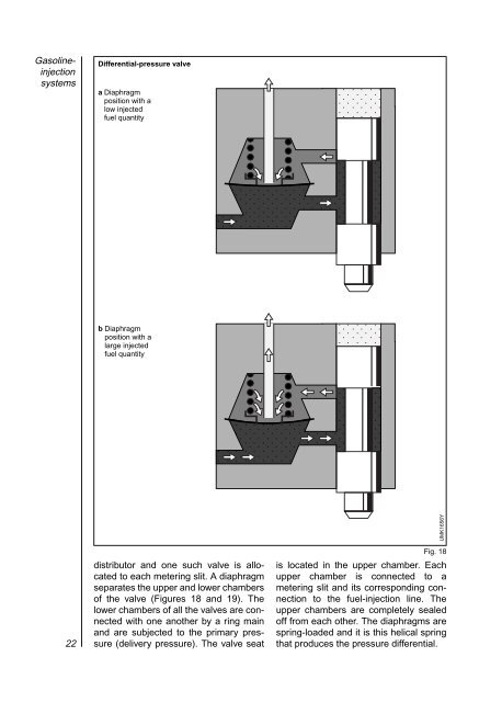
<strong>Gasoline</strong>injection systems Differential-pressure valve a Diaphragm position with a low injected fuel quantity ,,, ,,, ,,, ,,,,,,,, ,,,,,,,, ,,,,,,,, ,,,,,,,, ,,,,,,,, , , , , b Diaphragm position with a large injected fuel quantity ,,, ,,, ,,,,,,,, ,,,,,,,, ,,,,,,,, ,,,,,,,, ,,,,,,,, , , , , UMK1656Y 22 distributor and one such valve is allocated to each metering slit. A diaphragm separates the upper and lower chambers of the valve (Figures 18 and 19). The lower chambers of all the valves are connected with one another by a ring main and are subjected to the primary pressure (delivery pressure). The valve seat Fig. 18 is located in the upper chamber. Each upper chamber is connected to a metering slit and its corresponding connection to the fuel-injection line. The upper chambers are completely sealed off from each other. The diaphragms are spring-loaded and it is this helical spring that produces the pressure differential.
<strong>Fuel</strong> distributor with differential-pressure valves 1 <strong>Fuel</strong> intake (primary pressure), 2 Upper chamber of the differentialpressure valve, 2 3 4 5 6 3 Line to the fuelinjection valve ,,,, (injection ,,,, pressure), ,,,, 4 Control plunger, 5 Control edge and metering slit, 6 Valve spring, ,,,,,,,,,, 7 Valve diaphragm, ,,,,,,,,,, 8 Lower chamber of ,,,,,,,,,, the differentialpressure valve. ,,,,,,,,,, 1 ,,,,,,,,,, ,,,,,,,,,, ,,,,,,,,,, ,,,,,,,,,, ,,,,,,,,,, ,,,,,,,,,, ,,,,,,,,,, ,,,,,,,,,, K-<strong>Jetronic</strong> 8 7 UMK1602Y If a large basic fuel quantity flows into the upper chamber through the metering slit, the diaphragm is bent downwards and enlarges the valve cross-section at the outlet leading to the injection valve until the set differential pressure once again prevails. If the fuel quantity drops, the valve crosssection is reduced owing to the equilibrium of forces at the diaphragm until the differential pressure of 0.1 bar is again present. This causes an equilibrium of forces to prevail at the diaphragm which can be maintained for every basic fuel quantity by controlling the valve cross-section. Mixture formation The formation of the air-fuel mixture takes place in the intake ports and cylinders of the engine. The continually injected fuel coming from the injection valves is “stored” in front of the intake valves. When the intake valve is opened, the air drawn in by the engine carries the waiting “cloud” of fuel with it into the cylinder. An ignitable air-fuel mixture is formed during the induction stroke due to the swirl effect. Fig. 19 Fig. 20 Mixture formation with air-shrouded fuelinjection valve 1 <strong>Fuel</strong>-injection valve, 2 Air-supply line, 3 Intake manifold, 4 Throttle valve. ,,, @@@ €€€ ÀÀÀ ,,, @@@ €€€ ÀÀÀ ,, @@ €€ ÀÀ ,, @@ €€ ÀÀ ,, @@ €€ ÀÀ ,, @@ €€ ÀÀ ,, @@ €€ ÀÀ ,, @@ €€ ÀÀ ,, @@ €€ ÀÀ ,, @@ €€ ÀÀ ,, @@ €€ ÀÀ ,, @@ €€ ÀÀ 1 2 3 4 Air-shrouded fuel-injection valves favor mixture formation since they atomize the fuel very well at the outlet point (Figures 10, 20). UMK0068Y 23
- Page 1 and 2: Gasoline-engine management Gasoline
- Page 3 and 4: K-Jetronic Since its introduction,
- Page 5 and 6: As the piston travels upward it red
- Page 7 and 8: Ignition Finally, the “ignition
- Page 9 and 10: mechanically driven compressors pow
- Page 11 and 12: Adapting to specific operating cond
- Page 13 and 14: valves for intermittent fuel discha
- Page 15 and 16: K-Jetronic System overview The K-Je
- Page 17 and 18: The electric fuel pump delivers mor
- Page 19 and 20: holders to insulate them against th
- Page 21 and 22: ,,,, ,,,, The air-flow sensor is lo
- Page 23: Primary pressure and control pressu
- Page 27 and 28: Cold-start valve in operated state
- Page 29 and 30: The warm-up regulator comprises a s
- Page 31 and 32: Acceleration response The good acce
- Page 33 and 34: pressure in the lower chambers of t
- Page 35 and 36: Heated Lambda oxygen sensor To a la
- Page 37 and 38: Lambda closed control-loop The Lamb
- Page 39 and 40: consequently, does not inject extra
- Page 41 and 42: Fig. 44). And since the test is per