MINIMESS english version 2005 - Matelco
MINIMESS english version 2005 - Matelco
MINIMESS english version 2005 - Matelco

You also want an ePaper? Increase the reach of your titles
YUMPU automatically turns print PDFs into web optimized ePapers that Google loves.
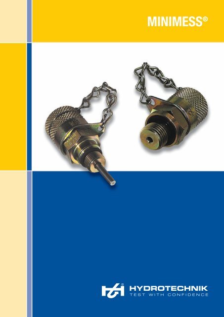
<strong>MINIMESS</strong> ®<br />
TEST WITH CONFIDENCE
Preface<br />
Pioneering technology and innovative solutions<br />
The company philosophy “Test with confidence” has a long tradition at Hydrotechnik. In 1964, the<br />
<strong>MINIMESS</strong> ® - ball sealing threaded test point and plug-in coupling was invented and proved to be a<br />
major advance for pressure measurement on hydraulic systems.<br />
The benefits of this innovative development were vast because up till then, pressure measurements<br />
had been mainly carried out with help of fixed mounted pressure gauges and with enormous expenditure.<br />
Now, with Hydrotechnik, the use of pressure sensors and pressure gauges could now be carried out<br />
quickly, safely and without any interruptions to plant. This is why we say “Test with confidence”.<br />
The next step: New sealing technique<br />
As a consequent development of the <strong>MINIMESS</strong> ® - plug-in and threaded<br />
test point with ball sealing from the 60’s, the patented leakage-free<br />
coupling with soft-sealing was introduced.<br />
The added benefits to our customers were at the forefront of<br />
our mind, meaning cleaner handling and new applications in<br />
problematic areas like water protection zones and for the<br />
first time also in gas application, which established<br />
HYDROTECHNIK even further in the market.<br />
p/T coupling - for requirements in the<br />
present and the future<br />
Handling, operating characteristics and quality of the MINI-<br />
MESS ® - test points have been proved a million times, however<br />
“Test with confidence” stands also for research and<br />
development. In order to offer more innovative products to our<br />
customers, new demands in the automation and robotics sector<br />
caused the next development. Our aim was to avoid measuring<br />
pessure and temperature with separate sensors. Instead, we wanted<br />
to use one common Test Point.<br />
Hydrotechnik developed the p/T - coupling, which was lengthened and designed<br />
to accept a temperature probe which actually gets in contact with the<br />
medium. Perfect heat transmission between the medium and the temperature sensor<br />
is guaranteed.<br />
Reliability and quality<br />
Everything<br />
begins at<br />
one point<br />
The high quality standard, connected with large process-security and non-leakage are reached by a<br />
modern automatic assembling with integrated leak testing.<br />
Due to this fact, ultra-modern test- and measurement couplings from Hydrotechnik are available to everyone.<br />
Today, <strong>MINIMESS</strong> ® - couplings are the basic requirement for measuring and testing in industry<br />
worldwide, due to its enormous environmental security and economy.<br />
Convince yourself and “Test with confidence”.
<strong>MINIMESS</strong> ® –<br />
One product for many applications<br />
Hydraulic control blocks<br />
Mobile load sensing systems<br />
Pump drives<br />
Cylinder controls<br />
Servo valves
Contents<br />
<strong>MINIMESS</strong> ® -Index<br />
6 <strong>MINIMESS</strong> ® – an overview<br />
7 <strong>MINIMESS</strong> ® -Technical data<br />
8 <strong>MINIMESS</strong> ® -1620 Test Points<br />
Metric DKO, Tee Adaptors - 1620<br />
Metric DKO 1620 Male/Female Tee Adaptors<br />
1620 Bulkhead Adaptors<br />
1620 Standpipe adaptor 37°-edged screwing SAE J514<br />
<strong>MINIMESS</strong> ® -1620 pressure gauge connection for bulkhead fitting<br />
<strong>MINIMESS</strong> ® -1620 pressure gauge - direct connection<br />
1620 90° Swivel screw connection<br />
<strong>MINIMESS</strong> ® -1620 Hose adaptors<br />
12 <strong>MINIMESS</strong> ® -1620 p/T Test Points<br />
13 <strong>MINIMESS</strong> ® -1215 Test Points<br />
Metric DKO, Tee Adaptors - 1215<br />
1215 Bulkhead Adaptors<br />
<strong>MINIMESS</strong> ® -1215 pressure gauge connection for bulkhead fitting<br />
<strong>MINIMESS</strong> ® -1215 pressure gauge - direct connection<br />
1215 90° Swivel screw connection<br />
<strong>MINIMESS</strong> ® -1215 hose adaptors<br />
16 <strong>MINIMESS</strong> ® -1615 Test Points<br />
<strong>MINIMESS</strong> ® -1615 specialised options<br />
Metric DKO, Tee Adaptors - 1615<br />
1615 Bulkhead adaptors<br />
<strong>MINIMESS</strong> ® -1615 pressure gauge connection for bulkhead fitting<br />
<strong>MINIMESS</strong> ® -1615 pressure gauge - direct connection<br />
1615 90° Swivel screw connection<br />
<strong>MINIMESS</strong> ® -1615 Hose Adaptors<br />
19 <strong>MINIMESS</strong> ® -1604 Test Points<br />
19 <strong>MINIMESS</strong> ® -Plug-in Test Points<br />
20 <strong>MINIMESS</strong> ® -Pressure inhibitors and accessories<br />
21 <strong>MINIMESS</strong> ® -Technical data on DN2 and DN4 microbore hose<br />
23 Mounting suggestions of <strong>MINIMESS</strong> ® microbore hose assemblies<br />
24 <strong>MINIMESS</strong> ® -DN2 microbore hose assemblies 1620,1615, 1215 and plug-in series<br />
Measuring hoses DN2 with protection against leakage<br />
25 <strong>MINIMESS</strong> ® -DN4 microbore hose assemblies 1604<br />
Measuring hoses DN4 with protection against leakage<br />
26 Order chart for hose material and accesories DN2 and DN4<br />
27 Selectable hose ends for DN2 and DN4 hose<br />
31 Accessories for <strong>MINIMESS</strong> ® -hoses<br />
32 Digital pressure gauges<br />
<strong>MINIMESS</strong> ® -1620 Test kit with two digital pressure gauges<br />
33 Analogue pressure gauges<br />
<strong>MINIMESS</strong> ® -1620 Test kit with two analogue gauges<br />
35 Accumulator charging and testing devices<br />
36 <strong>MINIMESS</strong> ® -gas charging valve 1615<br />
37 Accumulator charging and testing devices<br />
37 Gas charging and testing devices with pressure reducer valve<br />
37 Gas charging and flushing devices with pressure reducer valve<br />
38 Compatibility table<br />
39 Con<strong>version</strong> table of pressure measuring units
<strong>MINIMESS</strong> ® – an overview<br />
<strong>MINIMESS</strong> ® -1620<br />
Thread of<br />
screw-cap<br />
Nominal Bore<br />
Max Pressure<br />
Material<br />
Sealing material<br />
Page<br />
M 16 x 2<br />
DN 2<br />
63,0 MPa<br />
Free-cutting steel<br />
1.0718<br />
Stainless steel<br />
1.4571<br />
NBR (Perbunan)<br />
FKM (Viton)<br />
8<br />
<strong>MINIMESS</strong> ® -p/T 1620<br />
Thread of<br />
screw-cap<br />
Nominal Bore<br />
Max Pressure<br />
Material<br />
Sealing material<br />
Page<br />
M 16 x 2<br />
DN 2<br />
63,0 MPa<br />
Free-cutting steel<br />
1.0718<br />
NBR (Perbunan)<br />
FKM (Viton)<br />
11<br />
<strong>MINIMESS</strong> ® -1215<br />
Thread of<br />
screw-cap<br />
Nominal Bore<br />
Max Pressure<br />
Material<br />
Sealing material<br />
Page<br />
Fixing thread 12<br />
DN 2<br />
63,0 MPa<br />
Free-cutting steel<br />
1.0718<br />
Stainless steel<br />
1.4571<br />
NBR (Perbunan)<br />
FKM (Viton)<br />
12<br />
<strong>MINIMESS</strong> ® -1615<br />
Thread of<br />
screw-cap<br />
Nominal Bore<br />
Max Pressure<br />
Material<br />
Sealing material<br />
Page<br />
M 16 x 1,5<br />
DN 2<br />
63,0 MPa<br />
Free-cutting steel<br />
1.0718<br />
Stainless steel<br />
1.4571<br />
NBR (Perbunan)<br />
FKM (Viton)<br />
15<br />
<strong>MINIMESS</strong> ® -1604<br />
Thread of<br />
screw-cap<br />
Nominal Bore<br />
Max Pressure<br />
Material<br />
Sealing material<br />
Page<br />
Fixing thread 16<br />
DN 4<br />
40,0 MPa<br />
Free-cutting steel<br />
1.0718<br />
NBR (Perbunan)<br />
FKM (Viton)<br />
18<br />
6 1 MPa =10 bar
t<br />
t<br />
t<br />
t<br />
t<br />
<strong>MINIMESS</strong> ® -Technical data<br />
Max. working pressure 63 MPa (630 bar) according to ISO 15171-2<br />
Material<br />
Coupling body and metal cap made of steel 1.0718<br />
Note: Unless stated otherwise, all products shown in this catalogue<br />
are made of free-cutting steel 1.0718<br />
Sealing<br />
Internal primary- and secondary sealing as well as sealing for<br />
screw-in threads are made of NBR (Perbunan). Option in FKM (Viton).<br />
Vibration<br />
NBR (Perbunan) and/or FKM (Viton) O-ring to prevent cap loosening<br />
due to vibration.<br />
Screw-in thread<br />
Large range of threads are available.<br />
Media application<br />
Suitable for hydraulic- and other oils on mineral oil basis<br />
Temperature ranges at applications with<br />
metal cap (standard)<br />
Sealing made of NBR (Perbunan): -25 °C to +100 °C,<br />
for a short time, can<br />
be also used up to +120 °C<br />
Sealing made of FKM (Viton) as option: -20 °C to +200 °C<br />
Application with plastic cap (option)<br />
and for both sealing materials: -20 °C to +100 °C<br />
Thread form data<br />
Form C<br />
Form E Form F Form G Form H<br />
G<br />
45°<br />
ø d2<br />
z°<br />
ø d1<br />
G<br />
45°<br />
ø d<br />
G<br />
45°<br />
a<br />
ø d<br />
G<br />
30°<br />
G<br />
45°<br />
2,5 +0,2<br />
0,5 +0,15<br />
b<br />
k<br />
a<br />
b<br />
b<br />
b<br />
Thread port according to<br />
DIN 3852 part 1 and part<br />
2, form Z (sealed with<br />
suitable sealant)<br />
Thread port according to SAEJ 514<br />
(UNF) or according to ISO 6149-1<br />
(sealed with O-ring)<br />
Thread Port up to Ø d according<br />
to DIN 3852 part 1 and<br />
part 2, from X (sealed with<br />
flat seal)<br />
Thread Port according to<br />
HYDROTECHNIK standard<br />
N901-01-14 (sealed with<br />
O-ring)<br />
Thread Port<br />
according to<br />
ANSI/ASME B<br />
1.20.1-1983 (self<br />
sealing thread)<br />
SAE J 514 (UNF)<br />
G b t<br />
ISO 7 / I - R1/8 5,5 9,5<br />
ISO 7 / I - R1/4 8,5 13,5<br />
G d 1 d 2 b k t a z°<br />
7/16-20 UNF 21,0 12,4 11,5 2,4 14,0 1,6 12,0<br />
1/2-20 UNF 23,0 14,0 11,5 2,4 14,0 1,6 12,0<br />
9/16-18 UNF 25,0 15,6 12,7 2,5 15,5 1,6 12,0<br />
3/4-16 UNF 30,0 20,6 14,3 2,5 17,5 2,4 15,0<br />
ISO 6149-1<br />
M 10 x 1 19,0 11,1 10,0 1,6 11,5 1,0 12,0<br />
M 12 x 1,5 19,0 13,8 11,5 2,4 14,0 1,5 15,0<br />
M 14 x 1,5 21,0 15,8 11,5 2,4 14,0 1,5 15,0<br />
M 16 x 1,5 24,0 17,8 13,0 2,4 15,5 1,5 15,0<br />
G d a b t<br />
ISO 228-G 1/8 15,0 1,0 8,0 13,0<br />
ISO 228-G 1/4 20,0 1,5 12,0 18,5<br />
ISO 228-G 3/8 23,0 2,0 12,0 18,5<br />
ISO 228-G 1/2 27,0 2,5 14,0 22,0<br />
M 12 x 1,5 18,0 1,5 12,0 18,5<br />
M 14 x 1,5 20,0 1,5 12,0 18,5<br />
M 16 x 1,5 22,0 1,5 12,0 18,5<br />
G d b t<br />
M 8 x 1 9,5 9,0 13,0<br />
M 10 x 1 11,5 9,0 13,0<br />
G<br />
t<br />
1/8 NPTF 12,0<br />
1/4 NPTF 17,5<br />
1/2 NPTF 22,9<br />
1 MPa =10 bar<br />
7
i<br />
<strong>MINIMESS</strong> ® -1620 Test Points<br />
ø 20<br />
H<br />
H<br />
+3 mm<br />
SW<br />
G<br />
Metal cap with anti vibration O-ring<br />
Plastic cap – Vibration Proof<br />
Torque in Nm<br />
Technical data<br />
Material:<br />
Free cutting steel<br />
1.0718<br />
Metal<br />
cap<br />
Material:<br />
Free cutting steel<br />
1.0718<br />
Plastic<br />
cap<br />
Material:<br />
Stainless steel<br />
1.4571<br />
Metal<br />
cap<br />
Thread<br />
G<br />
Type of seal<br />
A<br />
p max<br />
H<br />
in mm<br />
i<br />
in mm<br />
SW<br />
in mm<br />
Part-number<br />
with NBR - sealing<br />
Part-number<br />
with NBR - sealing<br />
Part-number<br />
with FKM - sealing<br />
M 8 x 1*<br />
M 10 x 1<br />
Form G<br />
6<br />
12<br />
25 MPa<br />
41<br />
37,5<br />
8,5<br />
8,5<br />
17<br />
17<br />
2103-01-32.00<br />
2103-01-33.00<br />
2103-30-32.00<br />
2103-30-33.00<br />
on request<br />
2703-01-33.10<br />
M 12 x 1,5<br />
30<br />
36<br />
10<br />
17<br />
2103-01-13.00<br />
2103-30-13.00<br />
on request<br />
M 14 x 1,5<br />
Form F<br />
40<br />
63 MPa<br />
36<br />
10<br />
19<br />
2103-01-14.00<br />
2103-30-14.00<br />
2703-01-14.10<br />
M 16 x 1,5<br />
60<br />
36<br />
10<br />
22<br />
2103-01-15.00<br />
2103-30-15.00<br />
on request<br />
M 14 x 1,5<br />
Form E**<br />
45<br />
35,5<br />
11<br />
19<br />
2103-01-96.00<br />
2103-30-96.00<br />
on request<br />
ISO 228-G 1/8<br />
18<br />
40 MPa<br />
38<br />
8<br />
17<br />
2103-01-17.00<br />
2103-30-17.00<br />
2703-01-17.10<br />
ISO 228-G 1/4<br />
ISO 228-G 3/8<br />
Form F<br />
40<br />
60<br />
63 MPa<br />
36<br />
36<br />
10<br />
10<br />
19<br />
22<br />
2103-01-18.00<br />
2103-01-16.00<br />
2103-30-18.00<br />
2103-30-16.00<br />
2703-01-18.10<br />
on request<br />
1/8 NPTF<br />
1/4 NPTF<br />
Form H<br />
–<br />
–<br />
40 MPa<br />
33<br />
33<br />
9,5<br />
16,5<br />
17<br />
17<br />
2103-01-46.00<br />
2103-01-47.00<br />
2103-30-46.00<br />
2103-30-47.00<br />
on request<br />
2703-01-47.10<br />
7/16-20 UNF<br />
9/16-18 UNF<br />
Form E<br />
20<br />
35<br />
63 MPa<br />
37<br />
36<br />
9<br />
10<br />
17<br />
19<br />
2103-01-21.00<br />
2103-01-53.00<br />
2103-30-21.00<br />
2103-30-53.00<br />
on request<br />
on request<br />
ISO 7/I-R 1/8<br />
ISO 7/I-R 1/4<br />
Form C<br />
–<br />
–<br />
40 MPa<br />
63 MPa<br />
33<br />
33<br />
13<br />
13<br />
17<br />
17<br />
2103-01-40.00<br />
2103-01-41.00<br />
2103-30-40.00<br />
2103-30-41.00<br />
on request<br />
on request<br />
* M8x1 - Please do not use for new machinery design.<br />
** Form E – ISO 6149-2.<br />
Option<br />
For sealing in FKM (Viton) Exchange end digits from 00 to 10<br />
10<br />
Other materials, designs, sealing and screw-in threads on request.<br />
We reserve the right to carry out technical modifications.<br />
8 1 MPa =10 bar
ø<br />
d<br />
<strong>MINIMESS</strong> ® -1620 Test Points<br />
Metric DKO, Tee Adaptors - 1620<br />
For solder free screw-in pipe connections according to DIN 2353; free-cutting steel 1.0718; sealing NBR<br />
ø 20<br />
ø 20<br />
ø 20<br />
L0<br />
L0<br />
SW17<br />
SW<br />
SW<br />
Safety ring<br />
L0<br />
SW1<br />
SW2<br />
SW17<br />
G<br />
G<br />
G<br />
Fig. 1 ø d<br />
Fig. 2<br />
ø d<br />
L2<br />
ca.L1<br />
DKO - measuring connection with 24° sealing cone and Test Points incorporated.<br />
Elastic Perbunban O-ring at the sealing cone.<br />
Tee adapter c/w cutting rings with union nuts.<br />
Test Points incorporated.<br />
Series<br />
Ø d<br />
p max<br />
Thread<br />
G<br />
Fig.<br />
L o<br />
SW<br />
Part-number<br />
Part-number<br />
L 1 L 2<br />
49,5<br />
L o SW 1<br />
24 14<br />
SW 2<br />
2103-11-06.00<br />
L 6<br />
M 12 x 1,5<br />
52<br />
14<br />
2103-93-06.00<br />
50,5<br />
20,5<br />
L 8<br />
M 14 x 1,5<br />
52<br />
17<br />
2103-93-08.00<br />
50,5<br />
20,5<br />
49,5<br />
24<br />
17<br />
2103-11-08.00<br />
L 10<br />
31,5 MPa<br />
M 16 x 1,5<br />
1<br />
52<br />
19<br />
2103-93-10.00<br />
52,5<br />
22,5<br />
49,5<br />
24<br />
19<br />
2103-11-10.00<br />
L 12<br />
M 18 x 1,5<br />
52<br />
22<br />
2103-93-12.00<br />
52,5<br />
22,5<br />
49,5<br />
24<br />
22<br />
2103-11-12.00<br />
L 15<br />
M 22 x 1,5<br />
52<br />
27<br />
2103-93-15.00<br />
54,5<br />
24,5<br />
52,5<br />
30<br />
27<br />
2103-11-15.00<br />
L 18<br />
M 26 x 1,5<br />
52<br />
32<br />
2103-93-18.00<br />
56,5<br />
23,5<br />
53,5<br />
32<br />
32<br />
2103-11-18.00<br />
L 22<br />
M 30 x 2<br />
60<br />
36<br />
2103-40-22.00<br />
60,5<br />
27,5<br />
55,5<br />
36<br />
36<br />
2103-11-22.00<br />
L 28<br />
L 35<br />
16 MPa<br />
M 36 x 2<br />
M 45 x 2<br />
2<br />
61<br />
63<br />
41<br />
50<br />
2103-40-28.00<br />
2103-40-35.00<br />
60,5<br />
68,5<br />
27,5<br />
25,5<br />
58<br />
60,5<br />
41<br />
46<br />
41<br />
50<br />
2103-11-28.00<br />
2103-11-35.00<br />
L 42<br />
M 52 x 2<br />
63<br />
60<br />
2103-40-42.00<br />
70,5<br />
24,5<br />
65<br />
55<br />
60<br />
2103-11-42.00<br />
S 6<br />
M 14 x 1,5<br />
52<br />
17<br />
2103-94-06.00<br />
54,5<br />
24,5<br />
49,5<br />
24<br />
17<br />
2103-12-06.00<br />
S 8<br />
M 16 x 1,5<br />
52<br />
19<br />
2103-94-08.00<br />
54,5<br />
24,5<br />
49,5<br />
24<br />
19<br />
2103-12-08.00<br />
S 10<br />
63 MPa<br />
M 18 x 1,5<br />
1<br />
52<br />
22<br />
2103-94-10.00<br />
56,5<br />
23,5<br />
49,5<br />
24<br />
22<br />
2103-12-10.00<br />
S 12<br />
M 20 x 1,5<br />
52<br />
24<br />
2103-94-12.00<br />
56,5<br />
23,5<br />
49,5<br />
24<br />
24<br />
2103-12-12.00<br />
S 14<br />
M 22 x 1,5<br />
2<br />
63<br />
27<br />
2103-41-14.00<br />
62,5<br />
26,5<br />
51<br />
27<br />
27<br />
2103-12-14.00<br />
S 16<br />
M 24 x 1,5<br />
1<br />
52<br />
30<br />
2103-94-16.00<br />
62,5<br />
25,5<br />
52,5<br />
30<br />
30<br />
2103-12-16.00<br />
S 20<br />
40 MPa<br />
M 30 x 2<br />
63<br />
36<br />
2103-41-20.00<br />
68,5<br />
25,5<br />
55,5<br />
36<br />
36<br />
2103-12-20.00<br />
S 25<br />
S 30<br />
M 36 x 2<br />
M 42 x 2<br />
2<br />
64,5<br />
66<br />
46<br />
50<br />
2103-41-25.00<br />
2103-41-30.00<br />
74,5<br />
80,5<br />
26,5<br />
27,5<br />
58<br />
60,5<br />
41<br />
46<br />
46<br />
50<br />
2103-12-25.00<br />
2103-12-30.00<br />
S 38<br />
31,5 MPa<br />
M 52 x 2<br />
69<br />
60<br />
2103-41-38.00<br />
91<br />
29<br />
65<br />
55<br />
60<br />
2103-12-38.00<br />
Options<br />
All sealing made of Viton with metal cap (when ordering, exchange end digits from 00 to 10) 10<br />
With mounted plastic cap (when ordering, exchange end digits from 00 to 90) 90<br />
All sealing made of Viton with plastic cap (when ordering, exchange end digits from 00 to 95) 95<br />
1 MPa =10 bar<br />
9
<strong>MINIMESS</strong> ® -1620 Test Points<br />
Metric DKO 1620 Male/Female Tee Adaptors<br />
For solder free screw-in pipe connections according to DIN 2353<br />
Series<br />
p max<br />
G1<br />
D1<br />
G2<br />
D2<br />
SW<br />
L<br />
Part-number<br />
L 6<br />
M 12 x 1,5<br />
6<br />
M 12 x 1,5<br />
6<br />
24<br />
44,5<br />
2103-KL-06.00<br />
L 8<br />
M 14 x 1,5<br />
8<br />
M 14 x 1,5<br />
8<br />
24<br />
44,5<br />
2103-KL-08.00<br />
37,5<br />
L 10<br />
31,5 MPa<br />
M 16 x 1,5<br />
10<br />
M 16 x 1,5<br />
10<br />
24<br />
47,5<br />
2103-KL-10.00<br />
L 12<br />
M 18 x 1,5<br />
12<br />
M 18 x 1,5<br />
12<br />
24<br />
48,5<br />
2103-KL-12.00<br />
L 15<br />
M 22 x 1,5<br />
15<br />
M 22 x 1,5<br />
15<br />
30<br />
51,5<br />
2103-KL-15.00<br />
G1<br />
D1<br />
D2<br />
G2<br />
L 18<br />
M 26 x 1,5<br />
18<br />
M 26 x 1,5<br />
18<br />
32<br />
55,5<br />
2103-KL-18.00<br />
L 22<br />
M 30 x 2<br />
22<br />
M 30 x 2<br />
22<br />
36<br />
58,5<br />
2103-KL-22.00<br />
SW<br />
ca.L<br />
L 28<br />
L 35<br />
16 MPa<br />
M 36 x 2<br />
M 45 x 2<br />
28<br />
35<br />
M 36 x 2<br />
M 45 x 2<br />
28<br />
35<br />
41<br />
46<br />
59<br />
68<br />
2103-KL-28.00<br />
2103-KL-35.00<br />
L 42<br />
M 52 x 2<br />
42<br />
M 52 x 2<br />
42<br />
55<br />
68<br />
2103-KL-42.00<br />
Series<br />
G1<br />
D1<br />
G2<br />
D2<br />
SW<br />
L<br />
Part-number<br />
S 6<br />
M 14 x 1,5<br />
6<br />
M 14 x 1,5<br />
6<br />
24<br />
46,5<br />
2103-KS-06.00<br />
S 8<br />
M 16 x 1,5<br />
8<br />
M 16 x 1,5<br />
8<br />
24<br />
48,5<br />
2103-KS-08.00<br />
S 10<br />
63 MPa<br />
M 18 x 1,5<br />
10<br />
M 18 x 1,5<br />
10<br />
24<br />
49,5<br />
2103-KS-10.00<br />
S 12<br />
M 20 x 1,5<br />
12<br />
M 20 x 1,5<br />
12<br />
24<br />
50<br />
2103-KS-12.00<br />
S 14<br />
M 22 x 1,5<br />
14<br />
M 22 x 1,5<br />
14<br />
27<br />
53,5<br />
2103-KS-14.00<br />
S 16<br />
M 24 x 1,5<br />
16<br />
M 24 x 1,5<br />
16<br />
30<br />
56,5<br />
2103-KS-16.00<br />
S 20<br />
40 MPa<br />
M 30 x 2<br />
20<br />
M 30 x 2<br />
20<br />
36<br />
64,5<br />
2103-KS-20.00<br />
S 25<br />
M 36 x 2<br />
25<br />
M 36 x 2<br />
25<br />
41<br />
66<br />
2103-KS-25.00<br />
<strong>MINIMESS</strong> ® -1620 Test Points<br />
1620 Bulkhead Adaptors<br />
For solder free screw-in pipe connections according to DIN 2353, to <strong>MINIMESS</strong> ® - 1620 Test Points, NBR sealing<br />
ø 20<br />
Thread<br />
G<br />
p max<br />
Connectoin<br />
L<br />
in mm<br />
L 1<br />
in mm<br />
SW<br />
in mm<br />
Part-number<br />
M 12 x 1,5<br />
L 6<br />
34<br />
67<br />
17<br />
2103-04-22.00<br />
M 14 x 1,5<br />
31,5 MPa<br />
L 8<br />
34<br />
67<br />
19<br />
2103-04-23.00<br />
SW<br />
13max.<br />
L1<br />
M 16 x 1,5<br />
L 10<br />
33,5<br />
66,5<br />
22<br />
2103-04-18.00<br />
L<br />
M 14 x 1,5<br />
S 6<br />
36<br />
69<br />
19<br />
2103-04-24.00<br />
G<br />
24°<br />
M 16 x 1,5<br />
M 18 x 1,5<br />
63 MPa<br />
S 8<br />
S 10<br />
33,5<br />
37<br />
66,5<br />
70<br />
22<br />
24<br />
2103-04-25.00<br />
2103-04-26.00<br />
ø<br />
20<br />
Thread<br />
G<br />
p max<br />
Connectoin<br />
Part-number<br />
70<br />
SW22<br />
13max.<br />
M 16 x 2<br />
63 MPa<br />
Both sides for <strong>MINIMESS</strong> ® 1620 (M 16 x 2)<br />
2103-04-16.00<br />
SW19<br />
G<br />
10 1 MPa =10 bar
<strong>MINIMESS</strong> ® -1620 Test Points<br />
1620 Standpipe adaptor 37° - edged screwing SAE J514<br />
NBR sealing<br />
ø 20<br />
L<br />
L<br />
Thread<br />
G<br />
p max<br />
Pipe Ø<br />
in mm<br />
Pipe Ø<br />
in inch<br />
L<br />
in mm<br />
SW<br />
in mm<br />
Part-number<br />
7/16-20 UNF<br />
60 MPa<br />
6<br />
1/4”<br />
55<br />
17<br />
2103-85-21.00<br />
SW<br />
1/2 -20 UNF<br />
42 MPa<br />
8<br />
5/16”<br />
56,5<br />
17<br />
2103-85-22.00<br />
G<br />
9/16-18 UNF<br />
3/4- 16 UNF<br />
31,5 MPa<br />
10<br />
12<br />
3/8”<br />
1/2”<br />
57,5<br />
60,5<br />
19<br />
22<br />
2103-85-23.00<br />
2103-85-24.00<br />
<strong>MINIMESS</strong> ® - pressure gauge connection for bulkhead fitting<br />
SW1<br />
G1<br />
Internal thread<br />
G1<br />
p max<br />
Connection<br />
G2<br />
L<br />
in mm<br />
SW<br />
in mm<br />
Note<br />
Part-number<br />
10 max.<br />
SW2<br />
G2<br />
ISO 228-G 1/4<br />
ISO 228-G 1/2<br />
1/4 NPT<br />
63 MPa<br />
1620 /<br />
M 16 x 2<br />
38<br />
42,5<br />
–<br />
19<br />
27<br />
19<br />
Without<br />
return valve<br />
2103-05-11.00<br />
2103-05-12.00<br />
2103-05-23.00<br />
<strong>MINIMESS</strong> ® -1620 pressure gauge – direct connection<br />
G<br />
Internal thread<br />
G<br />
p max<br />
L<br />
in mm<br />
SW<br />
in mm<br />
Part-number<br />
SW<br />
ISO 228-G 1/4<br />
14,5<br />
19<br />
2103-07-11.62<br />
L<br />
SW22<br />
ISO 228-G 1/2<br />
63 MPa<br />
17<br />
27<br />
2103-07-12.62<br />
1/4 NPT<br />
–<br />
19<br />
2103-07-23.62<br />
<strong>MINIMESS</strong> ® -1620<br />
90° Swivel screw connection<br />
NBR sealing<br />
L2<br />
SW<br />
Thread<br />
G<br />
p max<br />
L 1<br />
in mm<br />
L 2<br />
in mm<br />
SW<br />
in mm<br />
Part-number<br />
L1<br />
ISO 228-G 1/4<br />
63 MPa<br />
34,5 64,5 19<br />
2115-22-34.00<br />
G<br />
dka-ring<br />
Sealing on screw-in thread (hollow screw) via dka-ring, on hexagon via Gi-ring (NBR).<br />
Other options on request.<br />
<strong>MINIMESS</strong> ® -1620 hose adaptor<br />
G<br />
Thread<br />
G<br />
p max<br />
L<br />
in mm<br />
SW<br />
in mm<br />
Note<br />
Part-number<br />
L<br />
SW<br />
M 16 x 2<br />
63 MPa<br />
42<br />
17<br />
Without<br />
return valve<br />
2146-01-00.00<br />
G<br />
Other materials, further executions, sealing and screw-in threads on request.<br />
1 MPa =10 bar<br />
11
i<br />
<strong>MINIMESS</strong> ® -1620 p/T Test Points<br />
for pressure and temperature measurement<br />
G1/4<br />
ø20<br />
45°<br />
1,5<br />
ø11,5<br />
M10x1<br />
30°<br />
12<br />
27*)<br />
Thread forms<br />
only for p/T -<br />
screw coupling<br />
2,5 +0,2<br />
0,5 +0,15<br />
9<br />
25,5*)<br />
Form F<br />
Form G<br />
*) = recommended min. depth of drill<br />
H<br />
ø 20<br />
Torque in Nm<br />
Technical data<br />
Material:<br />
Free cutting steel<br />
1.0718<br />
Metal<br />
cap<br />
SW<br />
Thread<br />
G<br />
Type of sealing<br />
A<br />
p max<br />
H<br />
in mm<br />
i<br />
in mm<br />
L 0<br />
in mm<br />
L<br />
in mm<br />
SW<br />
in mm<br />
Part-number<br />
with NBR - sealing<br />
L0<br />
L<br />
G<br />
ISO 228-G 1/4<br />
M 10 x 1<br />
Form F<br />
Form G<br />
40<br />
12<br />
63 MPa<br />
36,5<br />
38<br />
10<br />
8,5<br />
16<br />
16<br />
14,5<br />
14,5<br />
19<br />
17<br />
2149-04-15.13<br />
2149-04-19.13<br />
L 0 = max. immersion depth in coupled state, L = not coupled state<br />
Option<br />
For FKM (Viton) - exchange end digits from 13 to 53 53<br />
Other materials, further options, sealing and screw-in threads on request.<br />
We reserve the right to carry out technical modifications.<br />
12 1 MPa =10 bar
i<br />
<strong>MINIMESS</strong> ® -1215 Test Points<br />
17<br />
ø 20<br />
SW17<br />
H<br />
SW<br />
H +3mm<br />
Metal cap with anti vibration O-ring<br />
G<br />
Plastic cap with integrated safety<br />
device against vibration<br />
Torque in Nm<br />
Technical data<br />
Material:<br />
Free cutting steel<br />
1.0718<br />
Metal<br />
cap<br />
Material:<br />
Free cutting steel<br />
1.0718<br />
Plastic<br />
cap<br />
Material:<br />
Stainless steel<br />
1.4571<br />
Metal<br />
cap<br />
Thread<br />
G<br />
Type of sealing<br />
A<br />
p max<br />
H<br />
in mm<br />
i<br />
in mm<br />
SW<br />
in mm<br />
Part-number<br />
with NBR - sealing<br />
Part-number<br />
with NBR - sealing<br />
Part-number<br />
with FKM - sealing<br />
M 8 x 1*<br />
M 10 x 1<br />
Form G<br />
6<br />
12<br />
25 MPa<br />
30<br />
30<br />
8,5<br />
8,5<br />
14<br />
14<br />
2101-06-32.00<br />
2101-06-33.00<br />
2101-01-32.00<br />
2101-01-33.00<br />
on request<br />
2701-06-33.10<br />
M 12 x 1,5<br />
30<br />
63 MPa<br />
29<br />
10<br />
17<br />
2101-06-13.00<br />
2101-01-13.00<br />
on request<br />
M 14 x 1,5<br />
ISO 228-G 1/8<br />
Form F<br />
40<br />
18<br />
40 MPa<br />
29<br />
30<br />
10<br />
8<br />
19<br />
14<br />
2101-06-14.00<br />
2101-06-17.00<br />
2101-01-14.00<br />
2101-01-17.00<br />
on request<br />
on request<br />
ISO 228-G 1/4<br />
40<br />
63 MPa<br />
29<br />
10<br />
19<br />
2101-06-18.00<br />
2101-01-18.00<br />
2701-06-18.10<br />
1/8 NPTF<br />
1/4 NPTF<br />
Form H<br />
–<br />
–<br />
40 MPa<br />
26<br />
26<br />
12<br />
15<br />
14<br />
14<br />
2101-06-46.00<br />
2101-06-47.00<br />
2101-01-46.00<br />
2101-01-47.00<br />
on request<br />
2701-06-47.10<br />
7/16-20 UNF<br />
9/16-18 UNF<br />
Form E<br />
20<br />
35<br />
63 MPa<br />
29<br />
28<br />
9<br />
10<br />
17<br />
19<br />
2101-06-21.00<br />
2101-06-53.00<br />
2101-01-21.00<br />
2101-01-53.00<br />
on request<br />
on request<br />
ISO 7/I-R 1/8<br />
Form C<br />
–<br />
40 MPa<br />
26<br />
12<br />
14<br />
2101-06-40.00<br />
2101-01-40.00<br />
on request<br />
* M 8 x 1 – please do not use for new constructions.<br />
Option<br />
For FKM (Viton) - Exchange end digits from 00 to 10 10<br />
Other materials, further options, sealing and screw-in threads on request.<br />
We reserve the right to carry out technical modifications.<br />
1 MPa =10 bar<br />
13
<strong>MINIMESS</strong> ® -1215 Test Points<br />
Metric DKO, Tee Adaptors-1215<br />
For solder free screw-in pipe connections according to DIN 2353; execution free-cutting steel 1.0718; sealing NBR<br />
ø17<br />
ø 17<br />
ø 17<br />
SW14<br />
L0<br />
SW14<br />
L0<br />
SW<br />
SW<br />
Safety ring<br />
L0<br />
SW1<br />
SW2<br />
SW14<br />
G<br />
Fig. 1 Fig. 2<br />
ød<br />
G<br />
ø d<br />
d<br />
ø<br />
G<br />
L2<br />
ca. L1<br />
DKO - measuring connection with 24° sealing cone Safety ring and Test Points<br />
incorporated. Elastic Perbunban O-ring at the sealing cone.<br />
Tee adapter c/w cutting rings and union nuts.<br />
Test Points incorporated.<br />
Series<br />
Ø d<br />
p max<br />
Thread<br />
G<br />
Fig.<br />
L o<br />
SW<br />
Part-number<br />
SW 1 Part-number<br />
2101-11-06.90<br />
L 1 L 2<br />
42<br />
L o SW 1<br />
24 14<br />
L 6<br />
M 12 x 1,5<br />
62<br />
17<br />
2101-40-06.90<br />
50,5<br />
20,5<br />
L 8<br />
M 14 x 1,5<br />
62<br />
19<br />
2101-40-08.90<br />
50,5<br />
20,5<br />
42<br />
24<br />
17<br />
2101-11-08.90<br />
L 10<br />
31,5 MPa<br />
M 16 x 1,5<br />
1<br />
62<br />
19<br />
2101-40-10.90<br />
52,5<br />
22,5<br />
42<br />
24<br />
19<br />
2101-11-10.90<br />
L 12<br />
M 18 x 1,5<br />
58<br />
22<br />
2101-40-12.90<br />
52,5<br />
22,5<br />
42<br />
24<br />
22<br />
2101-11-12.90<br />
L 15<br />
M 22 x 1,5<br />
51,5<br />
27<br />
2101-40-15.90<br />
54,5<br />
24,5<br />
45<br />
30<br />
27<br />
2101-11-15.90<br />
L 18<br />
M 26 x 1,5<br />
52,5<br />
32<br />
2101-40-18.90<br />
56,5<br />
23,5<br />
46<br />
32<br />
32<br />
2101-11-18.90<br />
L 22<br />
L 28<br />
16 MPa<br />
M 30 x 2<br />
M 36 x 2<br />
2<br />
52,5<br />
53,5<br />
36<br />
41<br />
2101-40-22.90<br />
2101-40-28.90<br />
60,5<br />
60,5<br />
27,5<br />
27,5<br />
48<br />
50,5<br />
36<br />
41<br />
36<br />
41<br />
2101-11-22.90<br />
2101-11-28.90<br />
L 35<br />
M 45 x 2<br />
55,5<br />
50<br />
2101-40-35.90<br />
68,5<br />
25,5<br />
53<br />
46<br />
50<br />
2101-11-35.90<br />
L 42<br />
M 52 x 2<br />
55,5<br />
60<br />
2101-40-42.90<br />
70,5<br />
24,5<br />
57,5<br />
55<br />
60<br />
2101-11-42.90<br />
S 6<br />
M 14 x 1,5<br />
62<br />
17<br />
2101-41-06.90<br />
54,5<br />
24,5<br />
42<br />
24<br />
17<br />
2101-12-06.90<br />
S 8<br />
M 16 x 1,5<br />
62<br />
19<br />
2101-41-08.90<br />
54,5<br />
24,5<br />
42<br />
24<br />
19<br />
2101-12-08.90<br />
S 10<br />
63 MPa<br />
M 18 x 1,5<br />
1<br />
62<br />
22<br />
2101-41-10.90<br />
56,5<br />
23,5<br />
42<br />
24<br />
22<br />
2101-12-10.90<br />
S 12<br />
M 20 x 1,5<br />
58<br />
24<br />
2101-41-12.90<br />
56,5<br />
23,5<br />
42<br />
24<br />
24<br />
2101-12-12.90<br />
S 14<br />
M 22 x 1,5<br />
55<br />
27<br />
2101-41-14.90<br />
62,5<br />
26,5<br />
43,5<br />
27<br />
27<br />
2101-12-14.90<br />
S 16<br />
M 24 x 1,5<br />
55<br />
30<br />
2101-41-16.90<br />
62,5<br />
25,5<br />
45<br />
30<br />
30<br />
2101-12-16.90<br />
S 20<br />
S 25<br />
40 MPa<br />
M 30 x 2<br />
M 36 x 2<br />
2<br />
55,5<br />
57<br />
36<br />
46<br />
2101-41-20.90<br />
2101-41-25.90<br />
68,5<br />
74,5<br />
25,5<br />
26,5<br />
48<br />
50,5<br />
36<br />
41<br />
36<br />
46<br />
2101-12-20.90<br />
2101-12-25.90<br />
S 30<br />
M 42 x 2<br />
58,5<br />
50<br />
2101-41-30.90<br />
80,5<br />
27,5<br />
53<br />
46<br />
50<br />
2101-12-30.90<br />
S 38<br />
31,5 MPa<br />
M 52 x 2<br />
61,5<br />
60<br />
2101-41-38.90<br />
91<br />
29<br />
57,5<br />
55<br />
60<br />
2101-12-38.90<br />
Options<br />
All sealing made of Viton with metal cap (when ordering, exchange end digits from 00 to 10)<br />
00<br />
With mounted plastic cap (when ordering, exchange end digits from 00 to 90) 95<br />
Other materials, further options, sealing and screw-in threads on request.<br />
14 1 MPa =10 bar
<strong>MINIMESS</strong> ® -1215 Test Points<br />
1215 Bulkhead Adaptors<br />
For solder free screw-in pipe connections according to DIN 2353; execution free-cutting steel 1.0718; sealing NBR<br />
L<br />
ø 17<br />
Thread<br />
G<br />
p max<br />
Connection<br />
L<br />
in mm<br />
L 1<br />
in mm<br />
SW<br />
in mm<br />
Part-number<br />
SW<br />
13max.<br />
60,5 L1<br />
M 12 x 1,5<br />
M 14 x 1,5<br />
31,5 MPa<br />
L 6<br />
L 8<br />
34<br />
34<br />
60,5<br />
60,5<br />
17<br />
19<br />
2101-04-22.90<br />
2101-04-23.90<br />
d<br />
G<br />
24°<br />
M 14 x 1,5<br />
63 MPa<br />
S 6<br />
36<br />
62,5<br />
19<br />
2101-04-24.90<br />
SW19<br />
Thread<br />
G<br />
p max<br />
Connection<br />
Part-number<br />
65<br />
13 max.<br />
Fixing thread 12<br />
63 MPa<br />
On both sides <strong>MINIMESS</strong> ® - 1215 connection<br />
2101-04-16.90<br />
SW19<br />
G<br />
<strong>MINIMESS</strong> ® -1215 pressure gauge connection for bulkhead fitting<br />
SW1<br />
G1<br />
Internal thread<br />
G1<br />
p max<br />
Connection<br />
G2<br />
L in mm<br />
(approx.)<br />
SW<br />
in mm<br />
Note<br />
Part-number<br />
10 max.<br />
SW2<br />
ISO 228-G 1/4<br />
ISO 228-G 1/2<br />
63 MPa<br />
1215<br />
31<br />
38,5<br />
19<br />
27<br />
Without<br />
return valve<br />
2101-05-11.00<br />
2101-05-12.00<br />
G2<br />
1/4 NPT<br />
–<br />
22<br />
2101-05-23.00<br />
<strong>MINIMESS</strong> ® -pressure gauge – direct connection<br />
G<br />
Internal thread<br />
G<br />
p max<br />
L<br />
in mm<br />
SW<br />
in mm<br />
Part-number<br />
L<br />
SW<br />
SW 22<br />
ISO 228-G 1/4<br />
ISO 228-G 1/2<br />
63 MPa<br />
14,5<br />
17<br />
19<br />
27<br />
2101-07-11.62<br />
2101-07-12.62<br />
1/4 NPT<br />
–<br />
19<br />
2101-07-23.62<br />
<strong>MINIMESS</strong> ® -1215 Test Points<br />
1215 90° Swivel screw connection<br />
L2<br />
SW<br />
Thread<br />
G<br />
p max<br />
L 1<br />
in mm<br />
L 2<br />
in mm<br />
SW<br />
in mm<br />
Part-number<br />
L1<br />
ISO 228-G 1/4<br />
63 MPa<br />
34,5 46 19<br />
2115-22-14.00<br />
G<br />
dka-ring<br />
Sealing on screw-in thread (hollow screw) via dka-ring, on hexagon via Gi-ring (NBR).<br />
Other options on request.<br />
<strong>MINIMESS</strong> ® -1215 hose adaptors<br />
G<br />
Thread<br />
G<br />
p max<br />
L<br />
in mm<br />
SW<br />
in mm<br />
Note<br />
Part-number<br />
SW<br />
L<br />
Fixing thread 12<br />
63 MPa<br />
29 14 Without return valve<br />
2146-20-00.20<br />
G<br />
Other materials, further options, sealing and screw-in threads on request.<br />
1 MPa =10 bar<br />
15
i<br />
<strong>MINIMESS</strong> ® -1615 Test Points<br />
ø 20<br />
H<br />
SW<br />
G<br />
Metal cap with anti vibration O-ring<br />
Torque in Nm<br />
Technical data<br />
Material:<br />
Free cutting steel<br />
1.0718<br />
Metal<br />
cap<br />
Material:<br />
Stainless steel<br />
1.4571<br />
Metal<br />
cap<br />
Thread<br />
G<br />
Type of sealing<br />
A<br />
p max<br />
H<br />
in mm<br />
i<br />
in mm<br />
SW<br />
in mm<br />
Part-number<br />
with NBR - sealing<br />
Part-number<br />
with NBR - sealing<br />
M 10 x 1<br />
Form G<br />
12<br />
37,5<br />
8,5<br />
17<br />
2102-01-33.00<br />
2702-01-33.10<br />
M 12 x 1,5<br />
M 14 x 1,5<br />
M 16 x 1,5<br />
Form F<br />
Form B<br />
30<br />
40<br />
60<br />
63 MPa<br />
36<br />
36<br />
36<br />
10<br />
10<br />
10<br />
17<br />
19<br />
19<br />
2102-01-13.00<br />
2102-01-14.00<br />
2102-01-50.00<br />
on request<br />
on request<br />
on request<br />
ISO 228-G 1/4<br />
Form F<br />
40<br />
36<br />
10<br />
19<br />
2102-01-18.00<br />
2702-01-18.10<br />
1/4 NPTF<br />
Form H<br />
–<br />
33<br />
16,5<br />
17<br />
2102-01-47.00<br />
on request<br />
Option<br />
For FKM (Viton) Exchange end digits from 00 to 10 10<br />
<strong>MINIMESS</strong> ® -1615 Specialised Options<br />
Thread<br />
G<br />
Type of sealing<br />
p max<br />
H<br />
in mm<br />
L<br />
in mm<br />
SW<br />
in mm<br />
Execution all sealing made of Viton<br />
Part-number<br />
M 14 x 1,5<br />
Gi-ring<br />
36<br />
12<br />
19<br />
With anti vibration O-ring, alternative housing length<br />
2102-01-14.48<br />
ISO 228- G 1/4<br />
Sealing edge<br />
63 MPa<br />
38<br />
10<br />
19<br />
Low temperature -54°C to +110°C<br />
2102-01-51.56<br />
M 14 x 1,5<br />
Gi-ring<br />
36<br />
12<br />
19<br />
With sintered bronze filter<br />
2102-72-14.10<br />
Other materials, further options, sealing and screw-in threads on request.<br />
We reserve the right to carry out technical modifications.<br />
16 1 MPa =10 bar
<strong>MINIMESS</strong> ® -1615 Test Points<br />
Metric DKO, Tee Adaptors-1615<br />
For solder free screw-in pipe connections according to DIN 2353; execution free-cutting steel 1.0718; sealing NBR<br />
ø 20<br />
ø 20<br />
ø 20<br />
L0<br />
SW17<br />
L0<br />
SW17<br />
L0<br />
SW1<br />
SW<br />
SW<br />
Safety ring<br />
SW2<br />
SW17<br />
G<br />
Fig. 1 Fig. 2<br />
ø d<br />
G<br />
ø d<br />
L2<br />
ø d<br />
G<br />
ca.L1<br />
DKO - measuring connection with 24° sealing cone and Test Points incorporated.<br />
Elastic Perbunban O-ring at the sealing cone.<br />
Tee adapter c/w cutting rings and union nuts.<br />
Test Points incorporated.<br />
Series<br />
Ø d<br />
p max<br />
Thread<br />
G<br />
Fig.<br />
L o<br />
SW<br />
Part-number<br />
Part-number<br />
L 1 L 2<br />
49,5<br />
L 0 SW 1<br />
24 14<br />
SW 2<br />
2102-11-06.00<br />
L 6<br />
M 12 x 1,5<br />
69,5<br />
14<br />
2102-40-06.00<br />
50,5<br />
20,5<br />
L 8<br />
M 14 x 1,5<br />
69,5<br />
17<br />
2102-40-08.00<br />
50,5<br />
20,5<br />
49,5<br />
24<br />
17<br />
2102-11-08.00<br />
L 10<br />
31,5 MPa<br />
M 16 x 1,5<br />
1<br />
69,5<br />
19<br />
2102-40-10.00<br />
52,5<br />
22,5<br />
49,5<br />
24<br />
19<br />
2102-11-10.00<br />
L 12<br />
M 18 x 1,5<br />
65,5<br />
22<br />
2102-40-12.00<br />
52,5<br />
22,5<br />
49,5<br />
24<br />
22<br />
2102-11-12.00<br />
L 15<br />
M 22 x 1,5<br />
59<br />
27<br />
2102-40-15.00<br />
54,5<br />
24,5<br />
52,5<br />
30<br />
27<br />
2102-11-15.00<br />
L 18<br />
M 26 x 1,5<br />
60<br />
32<br />
2102-40-18.00<br />
56,5<br />
23,5<br />
53,5<br />
32<br />
32<br />
2102-11-18.00<br />
L 22<br />
L 28<br />
16 MPa<br />
M 30 x 2<br />
M 36 x 2<br />
2<br />
60<br />
61<br />
36<br />
41<br />
2102-40-22.00<br />
2102-40-28.00<br />
60,5<br />
60,5<br />
27,5<br />
27,5<br />
55,5<br />
58<br />
36<br />
41<br />
36<br />
41<br />
2102-11-22.00<br />
2102-11-28.00<br />
L 35<br />
M 45 x 2<br />
63<br />
50<br />
2102-40-35.00<br />
68,5<br />
25,5<br />
60,5<br />
46<br />
50<br />
2102-11-35.00<br />
L 42<br />
M 52 x 2<br />
63<br />
60<br />
2102-40-42.00<br />
70,5<br />
24,5<br />
65<br />
55<br />
60<br />
2102-11-42.00<br />
S 6<br />
M 14 x 1,5<br />
69,5<br />
17<br />
2102-41-06.00<br />
54,5<br />
24,5<br />
49,5<br />
24<br />
17<br />
2102-12-06.00<br />
S 8<br />
M 16 x 1,5<br />
69,5<br />
19<br />
2102-41-08.00<br />
54,5<br />
24,5<br />
49,5<br />
24<br />
19<br />
2102-12-08.00<br />
S 10<br />
63 MPa<br />
M 18 x 1,5<br />
1<br />
69,5<br />
22<br />
2102-41-10.00<br />
56,5<br />
23,5<br />
49,5<br />
24<br />
22<br />
2102-12-10.00<br />
S 12<br />
M 20 x 1,5<br />
65,5<br />
24<br />
2102-41-12.00<br />
56,5<br />
23,5<br />
49,5<br />
24<br />
24<br />
2102-12-12.00<br />
S 14<br />
M 22 x 1,5<br />
62,5<br />
27<br />
2102-41-14.00<br />
62,5<br />
26,5<br />
51<br />
27<br />
27<br />
2102-12-14.00<br />
S 16<br />
M 24 x 1,5<br />
62,5<br />
30<br />
2102-41-16.00<br />
62,5<br />
25,5<br />
52,5<br />
30<br />
30<br />
2102-12-16.00<br />
S 20<br />
40 MPa<br />
M 30 x 2<br />
2<br />
63<br />
36<br />
2102-41-20.00<br />
68,5<br />
25,5<br />
55,5<br />
36<br />
36<br />
2102-12-20.00<br />
S 25<br />
M 36 x 2<br />
64,5<br />
46<br />
2102-41-25.00<br />
74,5<br />
26,5<br />
58<br />
41<br />
46<br />
2102-12-25.00<br />
S 30<br />
M 42 x 2<br />
66<br />
50<br />
2102-41-30.00<br />
80,5<br />
27,5<br />
60,5<br />
46<br />
50<br />
2102-12-30.00<br />
S 38<br />
31,5 MPa<br />
M 52 x 2<br />
69<br />
60<br />
2102-41-38.00<br />
91<br />
29<br />
65<br />
55<br />
60<br />
2102-12-38.00<br />
Option<br />
All sealing made of Viton with metal cap (when ordering, exchange end digits from 00 to 10) 10<br />
Other materials, further options, sealing and screw-in threads on request.<br />
1 MPa =10 bar<br />
17
<strong>MINIMESS</strong> ® -1615 Test Points<br />
1615 Bulkhead Adaptors<br />
SW19<br />
Thread<br />
G<br />
M 16 x 1,5<br />
p max<br />
63 MPa<br />
Connection<br />
Part-number<br />
71<br />
12 max.<br />
L<br />
On both sides <strong>MINIMESS</strong> ® 1615 connection 2102-04-01.00<br />
SW19<br />
G<br />
<strong>MINIMESS</strong> ® -1615 pressure gauge connection for bulkhead fitting<br />
SW<br />
G1<br />
Internal thread<br />
G1<br />
p max<br />
Connection G2<br />
L<br />
in mm<br />
SW<br />
in mm<br />
Note<br />
Part-number<br />
10 min.<br />
SW 19<br />
ISO 228-G 1/4<br />
ISO 228-G 1/2<br />
63 MPa<br />
1615 /<br />
M 16 x 1,5<br />
38<br />
42,5<br />
19<br />
27<br />
Without<br />
return valve<br />
2102-05-11.00<br />
2102-05-12.00<br />
G2<br />
<strong>MINIMESS</strong> ® -1615 pressure gauge – direct connection<br />
G<br />
Internal thread<br />
G<br />
p max<br />
L<br />
in mm<br />
SW<br />
in mm<br />
Part-number<br />
SW<br />
ISO 228-G 1/4<br />
14,5<br />
19<br />
2102-07-11.62<br />
L<br />
SW 22<br />
ISO 228-G 1/2<br />
63 MPa<br />
17<br />
27<br />
2102-07-12.62<br />
1/4 NPT<br />
–<br />
19<br />
2102-07-23.62<br />
<strong>MINIMESS</strong> ® -1615 Test Points<br />
1615 90° Swivel screw connection<br />
SW<br />
L2<br />
Thread<br />
G<br />
p max<br />
L 1<br />
in mm<br />
L 2<br />
in mm<br />
SW<br />
in mm<br />
Part-number<br />
L1<br />
ISO 228-G 1/4<br />
63 MPa<br />
43 69,5 19<br />
2115-22-24.00<br />
G<br />
dka-ring<br />
Sealing on screw-in thread (hollow screw) via dka-ring, on hexagon via Gi-ring (NBR).<br />
Other options on request.<br />
<strong>MINIMESS</strong> ® -1615 Hose Adaptors<br />
G<br />
Thread<br />
G<br />
p max<br />
L<br />
in mm<br />
SW<br />
in mm<br />
Note<br />
Part-number<br />
L<br />
<strong>MINIMESS</strong> ® 1615<br />
SW 63 MPa 42 17 Without return valve<br />
M 16 x 1,5<br />
2146-10-00.00<br />
G<br />
Other materials, further options, sealing and screw-in threads on request.<br />
18 1 MPa =10 bar
H<br />
i<br />
<strong>MINIMESS</strong> ® -1604 Test Points<br />
ø 22<br />
G<br />
SW<br />
Metal cap with<br />
anti vibration O-ring<br />
Torque in Nm<br />
Technical data<br />
Material:<br />
Free cutting steel<br />
1.0718<br />
Metal<br />
cap<br />
Material:<br />
Stainless steel<br />
1.4571<br />
Metal<br />
cap<br />
Thread<br />
G<br />
Type of sealing<br />
A<br />
p max<br />
H<br />
in mm<br />
i<br />
in mm<br />
SW<br />
in mm<br />
Part-number<br />
with NBR - sealing<br />
Part-number<br />
with NBR - sealing<br />
M 10 x 1<br />
Form G<br />
12<br />
43<br />
8,5<br />
17<br />
2106-01-33.00<br />
on request<br />
M 14 x 1,5<br />
ISO 228-G 1/4<br />
Form F<br />
40<br />
40<br />
40 MPa<br />
40<br />
40<br />
10<br />
10<br />
19<br />
19<br />
2106-01-14.00<br />
2106-01-18.00<br />
on request<br />
2706-01-18.10<br />
Option<br />
For FKM (Viton) Exchange end digits from 00 to 10 10<br />
<strong>MINIMESS</strong> ® -plug-in Test Points<br />
Internal Ball Sealing<br />
ø15<br />
i H<br />
SW<br />
Plastic cap<br />
G<br />
Torque in Nm<br />
Technical data<br />
Material:<br />
Free cutting steel<br />
1.0718<br />
Material:<br />
Stainless steel<br />
1.4571<br />
Thread<br />
G<br />
Type of sealing<br />
A<br />
p max<br />
H<br />
in mm<br />
i<br />
in mm<br />
SW<br />
in mm<br />
Part-number<br />
with FKM - sealing<br />
Part-number<br />
with FKM - sealing<br />
M 8 x 1<br />
M 10 x 1<br />
ISO 7/ I-R 1/8<br />
1/8 NPT<br />
Form G<br />
Suitable<br />
sealant<br />
6<br />
12<br />
–<br />
–<br />
40 MPa<br />
17,5<br />
17,5<br />
17,5<br />
17,5<br />
8,5<br />
8,5<br />
8,5<br />
8,5<br />
12<br />
12<br />
12<br />
12<br />
2104-30-32.00<br />
2104-30-33.00<br />
2104-30-40.00<br />
2104-30-43.00<br />
2704-30-32.10<br />
on request<br />
on request<br />
on request<br />
1 MPa =10 bar<br />
19
i<br />
<strong>MINIMESS</strong> ® -Pressure inhibitors and accessories<br />
Pressure limiter valve<br />
n<br />
Used for protection of pressure gauges against overload<br />
65 max.<br />
ø19+0,4<br />
G2<br />
16,2<br />
15<br />
G1<br />
30<br />
Pressure gauge connection<br />
Working pressure max. 63 MPa<br />
Adjustable pressure range<br />
0,5 bis 0,9 MPa<br />
0,1 bis 2,5 MPa<br />
0,25 bis 6,3 MPa<br />
6,3 bis 10 MPa<br />
10 bis 25 MPa<br />
25 bis 60 MPa<br />
0,5 bis 0,9 MPa<br />
0,1 bis 2,5 MPa<br />
0,25 bis 6,3 MPa<br />
6,3 bis 10 MPa<br />
10 bis 25 MPa<br />
25 bis 60 MPa<br />
Pressure gauge connection<br />
G 1<br />
ISO 228-G 1/4<br />
according to<br />
DIN 16288<br />
ISO 228-G 1/2<br />
according to<br />
DIN 16288<br />
Connection G 2<br />
ISO 228-G 1/4<br />
according to<br />
DIN 3852<br />
Form X<br />
ISO 228-G 1/4<br />
according to<br />
DIN 3852<br />
Form X<br />
Part-number<br />
5110-01-20.00<br />
5110-02-20.00<br />
5110-03-20.00<br />
5110-04-20.00<br />
5110-05-20.00<br />
5110-07-20.00<br />
5110-01-30.00<br />
5110-02-30.00<br />
5110-03-30.00<br />
5110-04-30.00<br />
5110-05-30.00<br />
5110-07-30.00<br />
Restrictor valve<br />
ca.53<br />
SW36<br />
G1<br />
H<br />
G2<br />
ø19 +0,4<br />
Thread<br />
G1<br />
ISO 228-G 1/4<br />
ISO 228-G 1/2<br />
Thread<br />
G2<br />
ISO 228-G 1/4<br />
ISO 228-G 1/4<br />
H p max Execution<br />
53<br />
58<br />
63 MPa<br />
Adjustable under<br />
pressure up to 150 bar<br />
in-line connection<br />
Part-number<br />
5104-03-00.00<br />
5104-02-00.00<br />
Damping cartridge (snubber)<br />
18<br />
Borehole: nozzle<br />
Material<br />
Application<br />
Part-number<br />
M4<br />
M8x1<br />
ø 0,5 mm<br />
2.0401<br />
Choking element for dampening of fluidity vibrations<br />
2100-24-01.00<br />
Threaded adaptor M 10 x 1, Form G<br />
M 10 x 1<br />
External<br />
thread G<br />
Type<br />
of sealing<br />
H L SW<br />
p max<br />
in mm in mm in mm<br />
Part-number<br />
Free cutting steel 1.0718<br />
Part-number<br />
Stainless steel 1.4571<br />
M 12 x 1,5<br />
19<br />
10<br />
17<br />
2134-13-00.00<br />
auf Anfrage<br />
L<br />
SW<br />
ISO 228-G 1/8<br />
ISO 228-G 1/2<br />
Form F<br />
63 MPa<br />
19<br />
10<br />
8<br />
14<br />
17<br />
27<br />
2134-07-01.00<br />
2134-21-00.00<br />
2734-07-01.10<br />
2734-21-00.10<br />
G<br />
ISO 228-G 3/4<br />
1/2 NPTF<br />
Form H<br />
13<br />
10<br />
12<br />
18<br />
32<br />
24<br />
2134-51-00.00<br />
2134-45-01.01<br />
2734-51-00.10<br />
on request<br />
Welding adapter<br />
ø D<br />
G<br />
Thread<br />
G<br />
Screw-in hole<br />
p max<br />
L<br />
in mm<br />
SW<br />
in mm<br />
Part-number<br />
Free cutting steel 1.0718<br />
Part-number<br />
Stainless steel 1.4571<br />
M 10 x 1<br />
Form G<br />
25<br />
20<br />
2126-33-00.01<br />
on request<br />
L<br />
M 14 x 1,5<br />
ISO 228-G 1/4<br />
Form F<br />
63 MPa<br />
30<br />
22<br />
2126-04-00.01<br />
2126-08-00.01<br />
on request<br />
2726-08-00.01<br />
Other materials, further executions, sealing and screw-in threads on request.<br />
20 1 MPa =10 bar
<strong>MINIMESS</strong> ® -Technical data on DN2 and DN4 microbore hose<br />
DN 2 and DN 4<br />
Hose structure<br />
A D<br />
I D<br />
Hose Core:<br />
Polyamide<br />
Jacket: Polyamide<br />
Internal braid: Polyester fibre<br />
Nominal width<br />
Design<br />
Application<br />
p n<br />
p B<br />
in MPa in MPa<br />
I D<br />
in mm<br />
A D<br />
in mm<br />
r min Operable temperature range<br />
-20 °C up to +100 °C<br />
Pressure utilisation factor<br />
DN 2<br />
DN 2<br />
DN 2<br />
DN 4<br />
DN 4<br />
Standard 400<br />
Standard 630<br />
Low temperature<br />
Standard 315<br />
Standard 450<br />
Perforated<br />
hose<br />
40,0<br />
63,0<br />
63,0<br />
31,5<br />
45,0<br />
104,0<br />
195,0<br />
150,0<br />
81,0<br />
150,0<br />
2<br />
2<br />
2<br />
4<br />
4<br />
5<br />
5<br />
5<br />
8<br />
8<br />
20 mm<br />
(below -20 °C<br />
30 mm)<br />
40 mm<br />
(below -20 °C<br />
60 mm)<br />
short time up to +120 °C<br />
-54 °C up to +100 °C<br />
-20 °C up to +100 °C<br />
short time up to +120 °C<br />
0 °C 122% 30 °C 110%<br />
50 °C 100% 80 °C 86%<br />
100 °C 77% 120 °C 68%<br />
Example for calculation:<br />
<strong>MINIMESS</strong> ® -hose DN 2/63 MPa<br />
at 30 °C pressure utilisation<br />
facto: 63,0 x 1,10 = 69,3 MPa<br />
Reference of the specified data: 20 °C – 3 K<br />
p n = operating pressure<br />
p B = bursting pressure<br />
I D = internal diameter<br />
A D = external diameter<br />
r min = Minimum bend radius of hose<br />
Perforated hose = Jacket of hose is perforated for applications using gas<br />
Definition for the tightness of a <strong>MINIMESS</strong> ® -hose pipe<br />
“Technically tight” describes systems, part systems and functional elements if the leakage rate amounts to < 0,00001 mbar I s -1 .<br />
Criteria for selection of hoses and fittings<br />
1. Selection of the hose assembly for the maximum operating pressure (p N ):<br />
When ordering a hose assembly, you have to pay attention to the operating pressures of the hose material and of the connection<br />
fitting. The lowest pressure determines the max. operating pressure of the complete hose assembly.<br />
2. Selection of hose assembly for use with different media:<br />
Hose assemblies can be used with different media, as long as the end connections are suitable. To check the compatability for<br />
different media, please refer to our list on page 37.<br />
If your medium is not mentioned on page 37, please contact us!<br />
1 MPa =10 bar<br />
21
Fittings available with the following materials:<br />
Free cutting steel 1.0718 galvanized and chromated, acid-resistant stainless steel 1.4571 (antimagnetic)<br />
Identification<br />
Hose: Manufacturer’s stamp<br />
Nominal width DN.<br />
Year of manufacture<br />
Material (PA = polyamid)<br />
Operating pressure p N<br />
Hose Collar<br />
Date of manufacture, Month / Year<br />
Safety note: The hose assemblies have to be protected from flames and sharp-edged, hot objects.<br />
Pressure loss curve of DN 2 hose only<br />
Pressure loss curve of DN 2 hose assemblies<br />
Pressure loss ∆p (MPa/m)<br />
1,2<br />
1,0<br />
0,8<br />
0,6<br />
0,4<br />
0,2<br />
0,2 0,4 0,6 0,8 1,0 1,2<br />
Flow rate Q (l/min)<br />
Pressure loss in<br />
Mpa per metre<br />
of hose length<br />
without fittings,<br />
mineral oil: viscosity<br />
30 mm 2 s -1<br />
Pressure loss p (MPa/m)<br />
3,0<br />
2,5<br />
2,0<br />
1,5<br />
1,0<br />
0,5<br />
0,2 0,4 0,6 0,8 1,0 1,2<br />
Flow rate Q (l/min)<br />
Pressure loss in<br />
MPa through a<br />
hose assembly with<br />
a length of 1 m, with<br />
fittings and Test Points<br />
of series 1620 on both<br />
sides, mineral oil:<br />
viscosity 30 mm 2 s -1<br />
Pressure loss curve of DN 4 hoses<br />
Pressure loss curve of DN 4 hose pipes<br />
Pressure loss∆p (MPa/m)<br />
0,8<br />
0,7<br />
0,6<br />
0,5<br />
0,4<br />
0,3<br />
0,2<br />
0,1<br />
Pressure loss<br />
in Mpa per metre<br />
of hose length<br />
without fittings,<br />
mineral oil: viscosity<br />
30 mm 2 s -1<br />
Pressure loss∆p (MPa/m)<br />
4,0<br />
3,0<br />
2,0<br />
1,0<br />
Pressure loss in<br />
MPa through a<br />
hose assembly with<br />
a length of 1 m, with<br />
fittings and Test Points<br />
of series 1604 on both<br />
sides, mineral oil:<br />
viscosity 30 mm 2 s -1<br />
1 2 3 4 5 6 7 8<br />
Flow rate Q (l/min)<br />
1 2 3 4 5 6 7 8<br />
Flow rate Q (l/min)<br />
We guarantee a very high quality level of our <strong>MINIMESS</strong> ® -systems, as all components are manufactured very precisely and to tight<br />
tolerances. All parts in our <strong>MINIMESS</strong> ® -system are easy and safe to use. We reserve the right to carry out technical modifications!<br />
22 1 MPa =10 bar
Mounting suggestions of <strong>MINIMESS</strong> ® -hose assemblies<br />
Working reliability of a system and lifetime of the hose assembly are dependent on the<br />
correct installation. For this, here are some important notes:<br />
wrong<br />
Under load, the length of a hose pipe can change. A shortening causes an additional tensile<br />
stress of the hose and the connections. Therefore, the hose pipe needs “slack” in an unpressurised<br />
state. Please tighten the union nuts only so far using recommended tightening torques.<br />
Further tightening does not improve the operation, but can damage the connections.<br />
right<br />
wrong<br />
With curved assemblies, attention has to be paid to the bending radius. Sharp bends have to<br />
be avoided wherever possible. When calculating the length of a hose assembly, you have to<br />
pay attention to the fact that the connection fittings are not flexible. The correct calculation<br />
of the free hose length between the fittings is therefore essential.<br />
right<br />
wrong<br />
90° hose fittings are also available to aid in the fitting of hose assemblies to maximize life and<br />
operation of the assembly.<br />
right<br />
wrong<br />
90° hose fittings can also aid in the fitting of a tidy hose assembly in the tightest of porting<br />
requirements.<br />
right<br />
Notes for operation and installation<br />
In order to guarantee the operability of hoses and to not reduce assembly life by introducing additional strains, the following points<br />
have to be taken into consideration:<br />
n Hose assemblies may not be strained during operation by external influences like tension, torsion and upset.<br />
n The smallest mentioned bending radius of the hose must not be exceeded at any time.<br />
n Hose assemblies have to be protected against external damages caused by thermal, chemical or mechanical influences.<br />
n Painting or marking of hose assemblies should be avoided.<br />
Notes for storage of hose and hose assemblies<br />
n Store in cool, dry places and avoid direct UV-irradiation.<br />
n Sources of radiant heat should be avoided.<br />
n Ozone building light fittings and electronic instruments with sparking should be kept away from hoses and hose material (e.g.<br />
mercury vapor discharge lamps)<br />
n Optimum storage conditions are temperatures between +15°C and +25°C, a relative air humidity of 65%, as well as shielding<br />
against UV-radiation by special UV-impervious foils.<br />
n The storage time should not exceed four years for hose and two years for hose assemblies.<br />
1 MPa =10 bar<br />
23
<strong>MINIMESS</strong> ® -DN 2 microbore hose assemblies<br />
For 1620, 1615, 1215 and plug-in series<br />
L<br />
Fig. 1<br />
L<br />
p max<br />
Part-number<br />
p max<br />
Part-number<br />
200<br />
S 100-AC-AC-0020<br />
S 110-AC-AC-0020<br />
300<br />
S 100-AC-AC-0030<br />
S 110-AC-AC-0030<br />
400<br />
S 100-AC-AC-0040<br />
S 110-AC-AC-0040<br />
The tables show the series 1620<br />
n<br />
Suitable for hydraulic and other oils on<br />
mineral oil basis<br />
500<br />
630<br />
800<br />
S 100-AC-AC-0050<br />
S 100-AC-AC-0063<br />
S 100-AC-AC-0080<br />
S 110-AC-AC-0050<br />
S 110-AC-AC-0063<br />
S 110-AC-AC-0080<br />
n Same fittings on both sides<br />
n Fittings made of free cutting steel 1.0718<br />
1000<br />
1250<br />
40 MPa<br />
S 100-AC-AC-0100<br />
S 100-AC-AC-0125<br />
63 MPa<br />
S 110-AC-AC-0100<br />
S 110-AC-AC-0125<br />
1500<br />
S 100-AC-AC-0150<br />
S 110-AC-AC-0150<br />
2000<br />
S 100-AC-AC-0200<br />
S 110-AC-AC-0200<br />
2500<br />
S 100-AC-AC-0250<br />
S 110-AC-AC-0250<br />
3200<br />
S 100-AC-AC-0320<br />
S 110-AC-AC-0320<br />
4000<br />
S 100-AC-AC-0400<br />
S 110-AC-AC-0400<br />
5000<br />
S 100-AC-AC-0500<br />
S 110-AC-AC-0500<br />
Fittings made of<br />
stainless steel 1.4571<br />
Stainless Steel<br />
Exchange number 1 to 7,<br />
when ordering<br />
7<br />
7<br />
Series 1215 (picture 1)<br />
(fixing thread)<br />
When ordering, replace the<br />
letter codes with -AA-AA-.<br />
-AA-AA-<br />
Series 1615 (picture 1)<br />
(M 16 x 1,5)<br />
When ordering, replace the<br />
letter codes with -AB-AB-.<br />
-AB-AB-<br />
Plug-in series<br />
Max. pressure 40,0 MPa<br />
When ordering, replace the<br />
letter codes with -AI-AI-.<br />
-AI-AI-<br />
L<br />
DN 2 measuring hoses with protection against leakage<br />
with integrated return valve<br />
Series 1620<br />
(M 16x2)<br />
When ordering, replace<br />
both letter codes with<br />
-AR-AR-.<br />
-AR-AR-<br />
L<br />
Lmin = 300 mm<br />
-AR-AR-<br />
24 1 MPa =10 bar
<strong>MINIMESS</strong> ® -DN 4 microbore hose assemblies 1604<br />
for series 1604<br />
L<br />
Fig. 1<br />
L<br />
p max<br />
Part-number<br />
p max<br />
Part-number<br />
200<br />
S 150-AD-AD-0020<br />
S 160-AD-AD-0020<br />
300<br />
S 150-AD-AD-0030<br />
S 160-AD-AD-0030<br />
400<br />
S 150-AD-AD-0040<br />
S 160-AD-AD-0040<br />
n<br />
Suitable for hydraulic and other oils on<br />
mineral oil basis<br />
500<br />
630<br />
S 150-AD-AD-0050<br />
S 150-AD-AD-0063<br />
S 160-AD-AD-0050<br />
S 160-AD-AD-0063<br />
n Same fittings on both sides<br />
n Fittings made of free cutting steel 1.0718<br />
800<br />
1000<br />
1250<br />
31,5 MPa<br />
S 150-AD-AD-0080<br />
S 150-AD-AD-0100<br />
S 150-AD-AD-0125<br />
45 MPa<br />
S 160-AD-AD-0080<br />
S 160-AD-AD-0100<br />
S 160-AD-AD-0125<br />
1500<br />
S 150-AD-AD-0150<br />
S 160-AD-AD-0150<br />
2000<br />
S 150-AD-AD-0200<br />
S 160-AD-AD-0200<br />
2500<br />
S 150-AD-AD-0250<br />
S 160-AD-AD-0250<br />
3200<br />
S 150-AD-AD-0320<br />
S 160-AD-AD-0320<br />
4000<br />
S 150-AD-AD-0400<br />
S 160-AD-AD-0400<br />
5000<br />
S 150-AD-AD-0500<br />
S 160-AD-AD-0500<br />
Armaturen aus<br />
stainless steel 1.4571<br />
Stainless Steel<br />
Exchange number 1 to 7,<br />
when ordering 7<br />
7<br />
DN 4 measuring hoses with protection against leakage<br />
with integrated return valve<br />
Series 1604<br />
(fixing thread 16)<br />
When ordering, replace<br />
both letter codes with<br />
-AY-AY-.<br />
-AY-AY-<br />
L<br />
Lmin = 300 mm<br />
-AY-AY-<br />
Delivery effects with protective plugs on both sides.<br />
1 MPa =10 bar<br />
25
Order chart for hose material and accessories DN 2 and DN 4<br />
Options<br />
Part-number<br />
S XXX - XX - XX - XXXX<br />
Material of the fittings<br />
Free cutting steel 1.0718 galvanized and chromated<br />
Free cutting steel 1.0718 plus sealing for brake fluid<br />
Acid-resistant stainless steel 1.4571<br />
Stainless Steel<br />
1<br />
2<br />
7<br />
Hose material DN 2<br />
Perforated standard hose<br />
40,0 MPa<br />
DN 2<br />
0<br />
Perforated standard hose<br />
63,0 MPa<br />
1<br />
Perforated low temperature hose<br />
63,0 MPa<br />
2<br />
Hose material DN 4<br />
DN 4<br />
Perforated standard hose<br />
31,5 MPa<br />
5<br />
Perforated standard hose<br />
45,0 MPa<br />
6<br />
Standard<br />
Additional options<br />
Anti buckling spiral, left side (min. hose length 40 cm)<br />
Anti-buckling spiral, right side (min. hose length 40 cm)<br />
Anti-buckling spiral both sides (min. hose length 40 cm)<br />
Aluminium protection hose (min. hose length 40 cm)<br />
0<br />
1<br />
2<br />
3<br />
4<br />
Freely selectable fitting<br />
Input as a 2-digit fitting code from page 26 on<br />
Freely selectable fitting<br />
Input as a 2-digit fitting code from page 26 on<br />
Length L in cm (e.g. 30 cm = 0030 or 500 cm = 0500)<br />
Input as a 4-digit group of figures<br />
L in cm<br />
Attention: Aluminium protection in combination with an anti-buckling spiral is not possible.<br />
26 1 MPa =10 bar
Selectable hose ends for DN 2 and DN 4 hose<br />
Free cutting steel 1.0718 galvanized and chromated<br />
<strong>MINIMESS</strong> ® -connection<br />
Fig. 1<br />
Fig. 3<br />
D<br />
ø<br />
G<br />
2119-05-00.00<br />
2119-06-00.00<br />
2119-07-00.00<br />
3<br />
3<br />
3<br />
1215<br />
1615<br />
1620<br />
63<br />
63<br />
63<br />
20<br />
20<br />
20<br />
35<br />
35<br />
35<br />
AA<br />
AB<br />
AC<br />
L<br />
2119-14-00.00<br />
3<br />
Plug-in<br />
40<br />
22<br />
35<br />
AD<br />
<strong>MINIMESS</strong> ® -connection 90°<br />
Fig. 1<br />
L<br />
Thread p max ø D<br />
Part-number Fig.<br />
L L<br />
in MPa in mm<br />
1<br />
G<br />
Fitting code<br />
1<br />
ø D<br />
G<br />
Fittings<br />
Part-number<br />
Fig.<br />
Thread<br />
G<br />
p max<br />
in MPa<br />
ø D<br />
in mm<br />
L<br />
Fitting code<br />
Fig. 2<br />
L<br />
DN 2<br />
2119-02-00.00<br />
2119-03-00.00<br />
2119-04-00.00<br />
1<br />
1<br />
1<br />
1215<br />
1615<br />
1620<br />
63<br />
63<br />
63<br />
20<br />
20<br />
20<br />
22<br />
20<br />
20<br />
AA<br />
AB<br />
AC<br />
L<br />
2119-21-00.00<br />
2<br />
Plug-in<br />
40<br />
–<br />
30,5<br />
AI<br />
DN 4<br />
Fittings<br />
L<br />
SW<br />
DN 2<br />
2119-02-01.00<br />
2119-03-01.00<br />
1<br />
1215<br />
1615<br />
63<br />
63<br />
20<br />
20<br />
35,5<br />
35,5<br />
17,5<br />
17,5<br />
AJ<br />
AK<br />
G<br />
2119-04-01.00<br />
1620<br />
63<br />
20<br />
35,5<br />
17,5<br />
AL<br />
<strong>MINIMESS</strong> ® -connection with non-return valve<br />
Fig. 1<br />
Fittings<br />
Part-number<br />
Fig.<br />
Thread<br />
G<br />
p max<br />
in MPa<br />
ø D<br />
in mm<br />
L<br />
Fitting code<br />
D<br />
G<br />
ø<br />
DN 2<br />
2119-04-04.00<br />
1 1620 63<br />
20<br />
50<br />
AR<br />
L<br />
DN 4<br />
2119-09-04.00<br />
1 1604 40 24 70 AY<br />
<strong>MINIMESS</strong> ® -connection with hexagon clamping nut<br />
Fig. 1<br />
SW<br />
Fittings<br />
Thread p max ø D<br />
Part-number Fig.<br />
L L<br />
G in MPa in mm<br />
1<br />
Fitting code<br />
G<br />
2119-02-03.00<br />
1215<br />
63<br />
19<br />
38<br />
22<br />
AM<br />
L1<br />
DN 2<br />
2119-03-03.00<br />
1<br />
1615<br />
63<br />
19<br />
38<br />
20<br />
AN<br />
L<br />
2119-04-03.00<br />
1620<br />
63<br />
19<br />
38<br />
20<br />
AO<br />
1 MPa =10 bar<br />
27
Pressure gauge connection according to DIN 16 288 with O-ring sealing<br />
Fig. 1<br />
SW<br />
Fittings<br />
Thread p max SW<br />
Part-number Fig.<br />
L L<br />
in MPa in mm<br />
1<br />
G<br />
Fitting code<br />
G<br />
L<br />
DN 2<br />
5140-20-21.00<br />
5140-20-22.00<br />
1<br />
ISO 228-G 1/4<br />
ISO 228-G 1/2<br />
63<br />
63<br />
17<br />
27<br />
28,5<br />
31,5<br />
–<br />
–<br />
FG<br />
FH<br />
Pressure gauge connection according to DIN 16 288 - 90° with O-ring sealing<br />
Fig. 1<br />
G<br />
SW<br />
Fittings<br />
Thread p max SW<br />
Part-number Fig.<br />
L L<br />
in MPa in mm<br />
1<br />
G<br />
Fitting code<br />
L1<br />
L<br />
DN 2<br />
5140-20-23.00<br />
5140-20-24.00<br />
1<br />
ISO 228-G 1/4<br />
ISO 228-G 1/2<br />
63<br />
63<br />
17<br />
27<br />
43,5<br />
43<br />
32<br />
43<br />
FI<br />
FJ<br />
DKO - connection “light (L) and heavy (S) series”<br />
for solder free screw-in pipe connections according to DIN 2353 (24°)<br />
Fig. 1<br />
Fittings<br />
Part-number<br />
Fig.<br />
Series<br />
Thread<br />
G<br />
p max SW<br />
in MPa in mm<br />
L<br />
Fitting code<br />
5140-06-03.00<br />
L 6<br />
M 12 x 1,5<br />
31,5<br />
14<br />
30<br />
CQ<br />
SW<br />
DN 2<br />
5140-06-04.00<br />
5140-06-07.00<br />
1<br />
L 8<br />
L 10<br />
M 14 x 1,5<br />
M 16 x 1,5<br />
31,5<br />
31,5<br />
17<br />
19<br />
34<br />
33,5<br />
CR<br />
CS<br />
G<br />
5140-06-08.00<br />
L 12<br />
M 18 x 1,5<br />
31,5<br />
22<br />
33,5<br />
CT<br />
L<br />
DN 2<br />
5140-06-01.00<br />
5140-06-02.00<br />
5140-06-05.00<br />
1<br />
S 6<br />
S 8<br />
S 10<br />
M 14 x 1,5<br />
M 16 x 1,5<br />
M 18 x 1,5<br />
63<br />
63<br />
63<br />
17<br />
19<br />
22<br />
30<br />
34<br />
33,5<br />
CU<br />
CV<br />
CW<br />
5140-06-06.00<br />
S 12<br />
M 20 x 1,5<br />
63<br />
24<br />
23,5<br />
CX<br />
5140-16-03.00<br />
L 6<br />
M 12 x 1,5<br />
31,5<br />
14<br />
40<br />
CQ<br />
DN 4<br />
5140-16-04.00<br />
5140-16-07.00<br />
1<br />
L 8<br />
L 10<br />
M 14 x 1,5<br />
M 16 x 1,5<br />
31,5<br />
31,5<br />
17<br />
19<br />
41<br />
44,5<br />
CR<br />
CS<br />
5140-16-08.00<br />
L 12<br />
M 18 x 1,5<br />
31,5<br />
22<br />
44,5<br />
CT<br />
5140-16-01.00<br />
S 6<br />
M 14 x 1,5<br />
63<br />
17<br />
40<br />
CU<br />
DN 4<br />
5140-16-02.00<br />
5140-16-05.00<br />
1<br />
S 8<br />
S 10<br />
M 16 x 1,5<br />
M 18 x 1,5<br />
63<br />
63<br />
19<br />
22<br />
41<br />
44,5<br />
CV<br />
CW<br />
5140-16-06.00<br />
S 12<br />
M 20 x 1,5<br />
63<br />
24<br />
44,5<br />
CX<br />
28 1 MPa =10 bar
DKO - connection “light (L) and heavy (S) series” 90°<br />
for solder free screw-in pipe connections according to DIN 2353 (24°)<br />
Fig. 1<br />
Fittings<br />
Part-number<br />
Fig.<br />
Series<br />
Thread<br />
G<br />
p max<br />
in MPa<br />
SW<br />
in mm<br />
L<br />
L 1<br />
Fitting code<br />
SW<br />
5140-06-13.00<br />
L 6<br />
M 12 x 1,5<br />
31,5<br />
14<br />
30<br />
32,5<br />
DA<br />
G<br />
90°<br />
DN 2<br />
5140-06-18.00<br />
5140-06-10.00<br />
1<br />
L 8<br />
L 10<br />
M 14 x 1,5<br />
M 16 x 1,5<br />
31,5<br />
31,5<br />
17<br />
19<br />
34 32,5<br />
33,5 37,5<br />
DB<br />
DC<br />
L<br />
L1<br />
5140-06-17.00<br />
L 12<br />
M 18 x 1,5<br />
31,5<br />
22<br />
33,5 37,5<br />
DD<br />
5140-06-15.00<br />
S 6<br />
M 14 x 1,5<br />
63<br />
17<br />
30<br />
32,5<br />
DE<br />
DN 2<br />
5140-06-19.00<br />
5140-06-14.00<br />
1<br />
S 8<br />
S 10<br />
M 16 x 1,5<br />
M 18 x 1,5<br />
63<br />
63<br />
19<br />
22<br />
34<br />
33,5<br />
32,5<br />
37,5<br />
DF<br />
DG<br />
5140-06-16.00<br />
S 12<br />
M 20 x 1,5<br />
63<br />
24<br />
23,5<br />
37,5<br />
DH<br />
Standpipes for solder free screw-in pipe connection according to DIN 2353<br />
Fig. 1<br />
Fittings<br />
Part-number<br />
Fig.<br />
Execution<br />
p max<br />
in MPa<br />
ø D<br />
in mm<br />
L<br />
L 1<br />
Fitting code<br />
ø D<br />
L<br />
DN 2<br />
5140-08-16.00<br />
5140-08-01.00<br />
5140-08-11.00<br />
1 straight<br />
10<br />
63<br />
63<br />
4<br />
6<br />
8<br />
35<br />
35<br />
35<br />
20<br />
20<br />
21<br />
BA<br />
BB<br />
BC<br />
L1<br />
5140-07-01.00<br />
63<br />
6,35<br />
35<br />
20<br />
BD<br />
DN 4<br />
5140-18-01.00<br />
5140-18-02.00<br />
1 straight<br />
63<br />
45<br />
6<br />
8<br />
48<br />
47<br />
20<br />
21<br />
BB<br />
BC<br />
Standpipes, 90°, for solder free screw-in pipe connection acc. to DIN 2353<br />
Fig. 1<br />
L1<br />
Fittings<br />
p max ø D<br />
Part-number Fig. Execution<br />
L L<br />
in MPa in mm<br />
1<br />
Fitting code<br />
øD<br />
90°<br />
DN 2<br />
5140-08-02.00<br />
1 90° 63<br />
6<br />
30<br />
28<br />
BG<br />
L<br />
DN 4<br />
5140-08-12.00 1 90° 63 6 48 25 BG<br />
1 MPa =10 bar<br />
29
Male threaded connection<br />
Fig. 1<br />
L1<br />
L<br />
Fittings<br />
Thread p max SW<br />
Part-number Fig.<br />
L L<br />
in MPa in mm<br />
1<br />
G<br />
Fitting code<br />
DN 2<br />
5140-24-03.00<br />
1 ISO 228-G 1/8 40<br />
14<br />
26,5<br />
8<br />
GA<br />
ORS-connection<br />
Fig. 1<br />
SW<br />
Fittings<br />
Thread p max SW<br />
Part-number Fig.<br />
L L<br />
in MPa in mm<br />
1<br />
G<br />
Fitting code<br />
5140-26-03.00<br />
1 11/16-16UN 40<br />
22<br />
26,5<br />
–<br />
HC<br />
L<br />
Banjo fitting with M10x1 Banjo Bolt<br />
Fig. 1<br />
41<br />
SW<br />
Thread p max SW<br />
Part-number Fig.<br />
L L<br />
G in MPa in mm<br />
1<br />
Fitting code<br />
5140-27-01.00<br />
1 M 10 x 1 20<br />
14<br />
28<br />
10<br />
IA<br />
G<br />
Banjo fitting to accept M10x1 Banjo Bolt according to DIN 7642<br />
Fig. 1<br />
D<br />
Part-number<br />
5140-27-02.00<br />
Fig.<br />
1 – 20<br />
p max SW<br />
in MPa in mm<br />
17<br />
L<br />
41<br />
–<br />
Fitting code<br />
IB<br />
ø 10<br />
L1<br />
L<br />
G<br />
SW<br />
G<br />
DN 2<br />
Fittings<br />
DN 2<br />
CU-Dichtring<br />
Fittings<br />
DN 2<br />
L<br />
DN 4<br />
5140-27-11.00 1 – 20 17 43,5 –<br />
IB<br />
30 1 MPa =10 bar
<strong>MINIMESS</strong> ® -hoses<br />
Accessories<br />
Hose material DN 2 and DN 4<br />
Hose material for self assembly<br />
Perforated hose, DN 2<br />
Perforated hose, DN 2<br />
Low temperature, Perforated hose, DN 2<br />
40,0 MPa<br />
63,0 MPa<br />
63,0 MPa<br />
Part-number<br />
2020-01-00.31<br />
2020-01-00.30<br />
2020-01-00.18<br />
Perforated hose, DN 4<br />
Perforated hose, DN 4<br />
31,5 MPa<br />
45,0 MPa<br />
2030-01-00.22<br />
2030-01-00.24<br />
Anti-buckling spiral<br />
Anti-buckling spiral for self assembly<br />
Anti-buckling spiral for DN 2<br />
Part-number<br />
2123-01-00.01<br />
Anti-buckling spiral for DN 4 2133-01-00.01<br />
Aluminium protection hose<br />
Aluminium protection hose for self assembly<br />
Aluminium protection hose DN 2<br />
In addition to this, 2 pieces end screw sockets are necessary<br />
End screw sockets DN 2<br />
Part-number<br />
2121-01-00.01<br />
2121-01-00.02<br />
Aluminium protection hose for self assembly<br />
Aluminium protection hose DN 4<br />
In addition to this, 2 pieces end screw sockets are necessary<br />
End screw sockets DN 4<br />
Part-number<br />
2131-01-00.01<br />
2131-01-00.02<br />
1 MPa =10 bar<br />
31
Digital pressure gauges<br />
ø 74<br />
51<br />
G 1/4 A<br />
rotatable display<br />
89<br />
30<br />
2<br />
SW24<br />
38<br />
Technical data<br />
n Pressure measuring ranges 60 bar,<br />
250 bar or 600 bar<br />
n Error limit 0,5 %<br />
n 4-digit display, 12,7 mm<br />
n High overload<br />
n Pressure peak<br />
min.- and max.-values<br />
n IP 65<br />
n 9-Volt battery, 5000 h<br />
Digital Pressure gauge are the best solution to carry out a local network independent<br />
pressure measurement. Accuracy, reliability and mechanical capacity make the digital<br />
pressure gauge perfect for carrying out different pressure measurements. The front<br />
panel, which can be turned through 350° allows easy reading of values in any<br />
mounting position.<br />
Axial turning is made by loosening the nut at the housing. Simple operation is carried<br />
out with a 3 button panel whereby pressure and pressure peaks can also be measured<br />
as well as min. and max. values.<br />
Measuring range<br />
0–60 bar<br />
0–250 bar<br />
0–600 bar<br />
Part-number<br />
9801-97-00.60<br />
9801-97-02.50<br />
9801-97-06.00<br />
<strong>MINIMESS</strong> ® -1620 pressure test kit with two digital pressure gauges<br />
Test kit with 1 digital pressure gauge<br />
Part-number<br />
Measuring range<br />
0–60 bar<br />
0–250 bar<br />
0–600 bar<br />
Identification<br />
4<br />
6<br />
9<br />
3101 - 81 - 0 X.50<br />
4, 6 or 9<br />
Test kit with 2 digital pressure gauges<br />
Part-number<br />
Measuring range<br />
0–60 bar<br />
0–250 bar<br />
0–600 bar<br />
Identification<br />
4<br />
6<br />
9<br />
3101 - 82 - X X.50<br />
Lower<br />
measuring range<br />
Higher<br />
measuring range<br />
32 1 MPa =10 bar
Analogue pressure gauges<br />
Ø 63<br />
1,6 %<br />
25<br />
6<br />
Display range<br />
0–10 bar (0–145 psi)<br />
Part-number<br />
9802-01-00.10<br />
0–16 bar (0–230 psi)<br />
9802-01-00.16<br />
EN 837-1<br />
psi<br />
bar<br />
21 ø 62<br />
8<br />
13<br />
ø 68,5<br />
0–25 bar (0–360 psi)<br />
0–40 bar (0–580 psi)<br />
0–60 bar (0–870 psi)<br />
0–100 bar (0–1450 psi)<br />
0–160 bar (0–2300 psi)<br />
9802-01-00.25<br />
9802-01-00.40<br />
9802-01-00.60<br />
9802-01-01.00<br />
9802-01-01.60<br />
Connection according<br />
to DIN EN 837-<br />
1 and EN 837-3<br />
ISO 228-G1/4 B<br />
0–250 bar (0–3600 psi)<br />
0–400 bar (0–5800 psi)<br />
0–600 bar (0–8700 psi)<br />
9802-01-02.50<br />
9802-01-04.00<br />
9802-01-06.00<br />
n Housing ø 63 mm/Stainless steel<br />
n Accuracy 1,6% of end value<br />
n Display range in bar and psi<br />
n Glycerine filled<br />
Part-number<br />
<strong>MINIMESS</strong> ® -1620 pressure test kit with two analogue pressure gauges<br />
Test kit with 2 digital pressure gauges<br />
Measuring range<br />
0–10 bar (0–145 psi)<br />
0–16 bar (0–230 psi)<br />
0–25 bar (0–360 psi)<br />
0–40 bar (0–580 psi)<br />
0–60 bar (0–870 psi)<br />
0–100 bar (0–1450 psi)<br />
0–160 bar (0–2300 psi)<br />
0–250 bar (0–3600 psi)<br />
0–400 bar (0–5800 psi)<br />
0–600 bar (0–8700 psi)<br />
Identification<br />
0<br />
1<br />
2<br />
3<br />
4<br />
5<br />
6<br />
7<br />
8<br />
9<br />
3101 - 14 - X X.50<br />
Smaller<br />
measuring range<br />
Larger<br />
measuring range<br />
Requested<br />
measuring range<br />
Test kit with 1 digital pressure gauge<br />
3101 - 13 - 0 X.50<br />
<strong>MINIMESS</strong> ® -pressure test kit for series 1215 When ordering, please exchange end digits to 30<br />
<strong>MINIMESS</strong> ® -pressure test kit for series 1615 When ordering, please exchange end digits to 40<br />
30<br />
40<br />
1 MPa =10 bar<br />
33
3<br />
Analogue pressure gauges<br />
Rear Entry<br />
Ø 63<br />
1,6 %<br />
Position after installation<br />
Display range<br />
0–10 bar (0–145 psi)<br />
Part-number<br />
9801-53-00.10<br />
0–16 bar (0–230 psi)<br />
9801-53-00.16<br />
91<br />
78<br />
EN 837-1<br />
psi<br />
bar<br />
ISO 228-G1/4 B<br />
ø 63<br />
ø 68<br />
0–25 bar (0–360 psi)<br />
0–40 bar (0–580 psi)<br />
0–60 bar (0–870 psi)<br />
0–100 bar (0–1450 psi)<br />
9801-53-00.25<br />
9801-53-00.40<br />
9801-53-00.60<br />
9801-53-01.00<br />
0–160 bar (0–2300 psi)<br />
9801-53-01.60<br />
Connection according<br />
to DIN EN 837-<br />
1 und EN 837-3<br />
62<br />
37<br />
3,5<br />
0–250 bar (0–3600 psi)<br />
0–400 bar (0–5800 psi)<br />
0–600 bar (0–8700 psi)<br />
9801-53-02.50<br />
9801-53-04.00<br />
9801-53-06.00<br />
Ø 80<br />
1,0 %<br />
25±1<br />
14,5 45,5 ±1<br />
Display range Part-number<br />
0–10 bar (0–145 psi)<br />
9801-35-00.10<br />
Cutting ring connection<br />
S6 according<br />
to DIN 3861<br />
M14x1,5<br />
EN 837-1<br />
psi<br />
bar<br />
SW22<br />
ø 80 ±0,5<br />
Note:<br />
Not glycerine filled<br />
0–16 bar (0–230 psi)<br />
0–25 bar (0–360 psi)<br />
0–40 bar (0–580 psi)<br />
0–60 bar (0–870 psi)<br />
0–100 bar (0–1450 psi)<br />
9801-35-00.16<br />
9801-35-00.25<br />
9801-35-00.40<br />
9801-35-00.60<br />
9801-35-01.00<br />
25<br />
45,5<br />
ø84<br />
ø80<br />
Chromated<br />
triangular front ring<br />
0–160 bar (0–2300 psi)<br />
0–250 bar (0–3600 psi)<br />
0–400 bar (0–5800 psi)<br />
0–600 bar (0–8700 psi)<br />
on request<br />
9801-35-02.50<br />
9801-35-04.00<br />
9801-35-06.00<br />
n Housing ø 63 mm or ø 80 mm/Stainless steel<br />
n Accuracy: 1,6% or 1,0% of end value<br />
n Display range in bar and psi<br />
n Glycerine filled<br />
Analogue pressure gauges<br />
Bottom Entry<br />
Ø 100<br />
1,0 %<br />
19<br />
53<br />
Display range<br />
0–10 bar (0–145 psi)<br />
Part-number<br />
on request<br />
0–16 bar (0–230 psi)<br />
on request<br />
0–25 bar (0–360 psi)<br />
9801-20-00.25<br />
EN 837-1<br />
ø100<br />
0–40 bar (0–580 psi)<br />
on request<br />
F<br />
psi<br />
bar<br />
87 ±0.5<br />
0–60 bar (0–870 psi)<br />
0–100 bar (0–1450 psi)<br />
0–160 bar (0–2300 psi)<br />
9801-20-00.60<br />
9801-20-01.00<br />
9801-20-01.60<br />
ISO 228-G1/2 B<br />
Connection shank<br />
according to<br />
DIN EN 837-1<br />
and EN 837-3<br />
0–250 bar (0–3600 psi)<br />
0–400 bar (0–5800 psi)<br />
0–600 bar (0–8700 psi)<br />
on request<br />
9801-20-04.00<br />
9801-20-06.00<br />
34 1 MPa = 10 bar
Accumulator charging and testing devices<br />
Easy-to-use gas charging valves with leak proof integrity are required for charging, discharging and pressure testing of hydraulic<br />
accumulators. HYDROTECHNIK fulfills these requirements with its gas charging valves.<br />
The quality of a gas charging valve is essential for the long term use in plants with high safety regulations. The valves are easy to<br />
use with a safe and reliable connection.<br />
The essential advantages:<br />
n Very good leak proof integrity, leakage<br />
<strong>MINIMESS</strong> ® -gas charging valve 1615<br />
Maximum working pressure 63 MPa<br />
H<br />
Torque in Nm<br />
i<br />
i<br />
ø 20<br />
G<br />
SW<br />
Screw-cap thread:<br />
M 16 x 1,5<br />
Compatible with the following media<br />
Inert gases, nitrogen and compressed air. Resistant against antifreeze, oil,<br />
anti corrosion oil, grease and fuel.<br />
Technical data<br />
Execution:<br />
Metal<br />
cap<br />
Thread<br />
G<br />
Type of sealing<br />
A<br />
p max<br />
H<br />
in mm<br />
i<br />
in mm<br />
SW<br />
in mm<br />
Operating temperature range<br />
Coupling<br />
material<br />
Part-number<br />
with FKM sealings<br />
M 12 x 1,5<br />
30<br />
36,5<br />
8,5<br />
17<br />
1.4571<br />
2402-01-13.50<br />
M 14 x 1,5<br />
ISO 228-G 1/4<br />
Form F<br />
40<br />
40<br />
63 MPa<br />
36,5<br />
36,5<br />
10<br />
10<br />
19<br />
19<br />
-20 °C bis +135 °C<br />
1.4104<br />
2402-01-14.00<br />
2402-01-18.00<br />
Recorded with inspection certificate 3.1 B in accordance to DIN EN 10204, certificate 2.2. in accordance to DIN EN 10204<br />
M 14 x 1,5 Form B 40 63 MPa 36,5 10 19 -33 °C bis +135°C 1.4104 2402-01-49.70<br />
Material<br />
Body: 1.4104 (C4)<br />
Pressure spring: 1.4310<br />
Screw cap: brass (blackened)<br />
Sealing<br />
Internal primary and secondary sealing as well as integral seat seal<br />
and anti vibration O-ring (to prevent loosening of the metal cap) made<br />
of Viton.<br />
Attention: Before using oxygen, please ensure you rinse and clean the gas charging valve.<br />
Adapter incorporating gas charging valve 1615 made of stainless steel<br />
ø20<br />
Thread of<br />
accumulator<br />
Type of hydraulic<br />
accumulator<br />
p max Material<br />
H<br />
in mm<br />
I<br />
in mm<br />
SW<br />
in mm<br />
Part-number<br />
with FKM - sealing<br />
H<br />
G<br />
SW30<br />
7/8“-14 UNF<br />
M 28 x 1,5<br />
Bosch-bubble accumul.<br />
Bosch-diaphragm accumul.<br />
63 MPa 1.4104<br />
73<br />
63<br />
36<br />
26<br />
30<br />
36<br />
2446-16-30.00<br />
2446-18-30.00<br />
Gas charging valve adapter 1615<br />
To be directly screwed on the original valve of the accumulator<br />
M16x1,5<br />
Thread of<br />
accumulator<br />
Type of hydraulic<br />
accumulator<br />
p max<br />
Material<br />
H<br />
in mm<br />
Part-number<br />
with FKM - sealing<br />
H<br />
G<br />
ø 25<br />
VG 8 DIN 7756<br />
5/16“-32 UNEF<br />
Langen<br />
US<br />
63 MPa 1.0718<br />
32<br />
32<br />
5414-02-00.00<br />
5414-02-10.00<br />
Surface protection: galvanized and chromated. Further screw-in threads on request.<br />
36 1 MPa = 10 bar
Accumulator charging and testing devices<br />
Pressure gauge<br />
display range<br />
Measuring connection<br />
Cylinder connection<br />
thread G<br />
H<br />
in mm<br />
L<br />
in mm<br />
SW<br />
in mm<br />
Part-number<br />
0–400 bar<br />
<strong>MINIMESS</strong> ® 1615<br />
W 24,32 x 1/14“<br />
124<br />
123<br />
28<br />
5114-01-00.10<br />
0–250 bar<br />
<strong>MINIMESS</strong> ® 1620<br />
W 24,32 x 1/14“<br />
124<br />
123<br />
28<br />
5114-21-03.00<br />
n<br />
n<br />
n<br />
Charging of the hydraulic accumulator<br />
Testing and lowering the pressure within the hydraulic accumulator<br />
Pressure gauge Cl. 1,6 - Ø 63 mm<br />
Complete measuring equipment kit on request.<br />
Gas charging and testing device with pressure reducer valve<br />
Secondary<br />
adjustment<br />
Pressure gauge display<br />
range, secondary<br />
Cylinder connection<br />
thread G<br />
Connection<br />
secondary<br />
SW<br />
in mm<br />
Part-number<br />
1,0–235 bar<br />
0–250 bar<br />
W 24,32 x 1/14“<br />
<strong>MINIMESS</strong> ® 1615<br />
28<br />
5401-02-00.00<br />
1,0–235 bar<br />
0–250 bar<br />
W 21,8 x 1/14“<br />
<strong>MINIMESS</strong> ® 1615<br />
28<br />
5401-02-02.00<br />
n<br />
n<br />
n<br />
Filling, adjusting and controlling gas pressure in hydraulic accumulators with nitrogen filling<br />
Pressure gauge Cl. 1,6 - Ø 63 mm<br />
Pressure gauge for primary pressure display 0 to 400 bar<br />
Complete measuring equipment kit on request.<br />
Gas charging and flushing device with pressure reducer valve<br />
for low pressure<br />
Secondary<br />
adjustment<br />
Pressure gauge display<br />
range, secondary<br />
Cylinder connection<br />
thread G<br />
Connection<br />
secondary<br />
SW<br />
in mm<br />
Part-number<br />
0–1,3 bar<br />
0–1,6 bar<br />
W 24,32 x 1/14“<br />
<strong>MINIMESS</strong> ® 1615<br />
28<br />
5401-07-00.00<br />
Complete measuring equipment with transport case and high pressure hose<br />
5401-07-00.10<br />
n<br />
n<br />
n<br />
n<br />
Pre-adjustment of the flushing- and charging pressure<br />
Flushing and charging of nitrogen systems<br />
Pressure gauge Cl. 1,6 - Ø 63 mm<br />
Pressure gauge for primary pressure display 0 to 250 bar<br />
1 MPa =10 bar<br />
37
Compatibility table<br />
n Sealing material: Viton<br />
n Free-cutting steel 1.0718 (9SMnPb28K), surface galvanized and chromated<br />
n Corrosion-resistant stainless steel 1.4104 (X 12CrMoS 17)<br />
n Acid proof stainless steel 1.4571 (X 10CrNiMoTi 1810) antimagnetic<br />
n Hoses: polyamide 11<br />
All statements are not binding and are only for your information<br />
Flow rate media<br />
Acetone<br />
Ethyl alcohol, pure<br />
Ammonia, concentrated<br />
Ammonia, liquid<br />
Formic acid<br />
Gasoline, pure<br />
Benzene<br />
Brake fluid<br />
Butane<br />
Cyclohexane<br />
Diesel motor fuel<br />
Freon 12<br />
Glycerin, pure<br />
Glycols<br />
Heating oil<br />
Hydraulic fluid (mineral oil base)<br />
Kerosene<br />
Carbon dioxide<br />
Methane<br />
Methyl alcohol, pure<br />
Mineral oils<br />
Petroleum<br />
Polyalkyleneglycol (HEPG)<br />
Propane<br />
Oxygen<br />
Lubricating oils and grease<br />
Soap solution<br />
Nitrogen<br />
Synthetic esters (HEES)<br />
Essence of turpentine<br />
Tetra chloromethane<br />
Toluene<br />
Trichloroethylene<br />
Triglycerides (HETG)<br />
Water<br />
Sea water<br />
Sealing<br />
3 *)<br />
1/2<br />
3 *)<br />
3 *)<br />
3 *)<br />
1<br />
1/2<br />
3 *)<br />
1<br />
1<br />
1<br />
1/2<br />
1/2<br />
1/2<br />
1<br />
1<br />
1<br />
1<br />
1<br />
3 *)<br />
1<br />
1<br />
2 (
Con<strong>version</strong> table of the pressure measuring units<br />
Units<br />
1 Pa = 1N/m 2<br />
PA<br />
N/m 2<br />
1<br />
MPa<br />
bar<br />
MN/m 2 10 -5<br />
10 -6<br />
mbar<br />
10 -2<br />
mWS<br />
1,02 x 10 -4<br />
1 MPa = 1MN/m 2 10 6<br />
1<br />
10<br />
10 4<br />
102<br />
1 bar<br />
10 5<br />
10 -1<br />
1<br />
10 3<br />
10,2<br />
1 mbar<br />
10 2<br />
10 -4<br />
10 -3<br />
1<br />
1,02 x 10 -2<br />
1 mWS 9,81 x 10 3 9,81 x 10 -3 9,81 x 10 -2 9,81 x 10 1<br />
1<br />
1 mmWS<br />
9,81<br />
9,81 x 10 -6 9,81 x 10 -5 9,81 x 10 -2<br />
10 -3<br />
1 mmHg (Torr) 1,33 x 10 2 1,33 x 10 -4 1,33 x 10 -3<br />
1,33<br />
1,36 x 10 -2<br />
1 psi<br />
6,89 x 10 3 6,89 x 10 -3 6,89 x 10 -2 6,89 x 10 1 7,03 x 10 -1<br />
1 kp/cm 2 (at) 9,81 x 10 4 9,81 x 10 -2 9,81 x 10 -1 9,81 x 10 2<br />
10<br />
Definition of the units:<br />
at Technical atmosphere<br />
kp/cm 2 Kilopond per square centimetre<br />
Pa Pascal<br />
MPa Mega-Pascal<br />
N/m 2 Newton per square centimetre<br />
MN/m 2 Mega-Newton per square centimetre<br />
bar bar<br />
mbar Millibar<br />
mWS Meter water pillar<br />
mmWs Millimetre water pillar<br />
mmHg Millimetre mercury pillar at = 0°C<br />
psi English pound per square inch<br />
mmWS<br />
1,02 x 10 -1<br />
1,02 x 10 5<br />
1,02 x 10 4<br />
10,2<br />
10 3<br />
1<br />
1,36 x 10 1<br />
7,03 x 10 2<br />
10 4<br />
mmHg<br />
(Torr)<br />
7,5 x 10 -3<br />
7500<br />
750<br />
7,5 x 10 -1<br />
7,36 x 10 1<br />
7,36 x 10 -2<br />
1<br />
5,17 x 10 1<br />
7,36 x 10 2<br />
psi<br />
1,45 x 10 -4<br />
145<br />
14,5<br />
1,45 x 10 -2<br />
1,42<br />
1,42 x 10 -3<br />
1,93 x 10 -2<br />
1<br />
1,42 x 10 1<br />
kp/cm 2<br />
(at)<br />
1,02 x 10 -5<br />
10,2<br />
1,02<br />
1,02 x 10 -3<br />
10 -1<br />
10 -4<br />
1,36 x 10 -3<br />
7,03 x 10 -2<br />
1
HYDROTECHNIK GmbH<br />
Holzheimer Straße 94 –96 | 65549 Limburg<br />
Tel. 0 64 31.40 04-0 | Fax 0 64 31.4 53 08<br />
www.hydrotechnik.com | info@hydrotechnik.com<br />
TEST WITH CONFIDENCE<br />
8898-01-00.71/<strong>2005</strong>