

38CKB(N) Wiring Diagrams - Carrier
38CKB(N) Wiring Diagrams - Carrier
38CKB(N) Wiring Diagrams - Carrier

You also want an ePaper? Increase the reach of your titles
YUMPU automatically turns print PDFs into web optimized ePapers that Google loves.
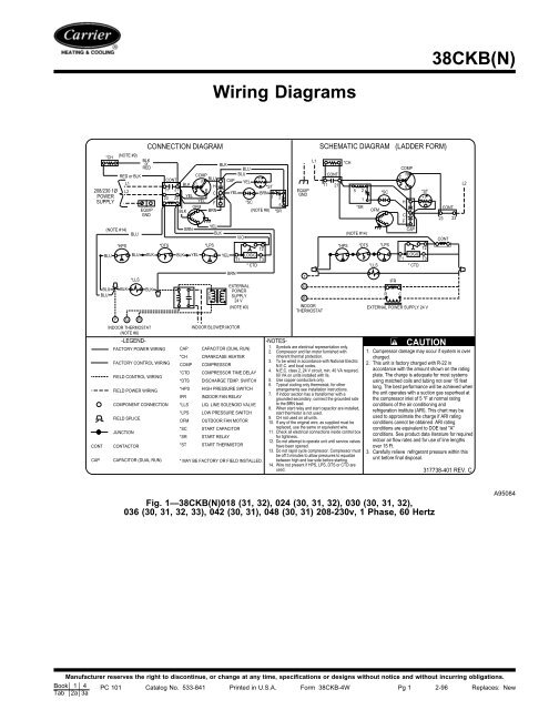
<strong>38CKB</strong>(N)<br />
<strong>Wiring</strong> <strong>Diagrams</strong><br />
CONT<br />
CAP<br />
*CH<br />
208/230 1Ø<br />
POWER<br />
SUPPLY<br />
Y G R<br />
INDOOR THERMOSTAT<br />
(NOTE #6)<br />
-LEGEND-<br />
FACTORY POWER WIRING<br />
FACTORY CONTROL WIRING<br />
FIELD CONTROL WIRING<br />
FIELD POWER WIRING<br />
COMPONENT CONNECTION<br />
FIELD SPLICE<br />
JUNCTION<br />
CONTACTOR<br />
BLK or<br />
RED<br />
CAPACITOR (DUAL RUN)<br />
CONNECTION DIAGRAM SCHEMATIC DIAGRAM (LADDER FORM)<br />
RED or BLK<br />
COMP<br />
CONT<br />
BLU<br />
L1<br />
S<br />
BLK C<br />
H<br />
L2 11 21<br />
R<br />
C<br />
23 23<br />
YEL<br />
YEL<br />
F<br />
EQUIP<br />
BLK<br />
OFM<br />
BRN<br />
GND<br />
(NOTE #14)<br />
BLU<br />
BLU<br />
BLU<br />
(NOTE #9)<br />
*HPS<br />
BLK<br />
BLU<br />
BLU<br />
*LLS<br />
BLK<br />
BLK<br />
*DTS<br />
BLK<br />
BRN<br />
CAP<br />
*CH<br />
COMP<br />
*CTD<br />
*DTS<br />
*HPS<br />
IFR<br />
*LLS<br />
*LPS<br />
OFM<br />
*SC<br />
*SR<br />
*ST<br />
YEL<br />
YEL<br />
BLK<br />
*LPS<br />
C<br />
R<br />
BLK<br />
BLU<br />
BLU<br />
CAP YEL<br />
+ t<br />
*ST<br />
YEL<br />
BRN<br />
1 2<br />
*SC<br />
5<br />
(NOTE #8) *SR<br />
YEL<br />
BRN<br />
INDOOR BLOWER MOTOR<br />
VIO<br />
T2<br />
LOGIC<br />
T1<br />
T3<br />
* CTD<br />
EXTERNAL<br />
POWER<br />
SUPPLY<br />
24 V<br />
(NOTE #3)<br />
CAPACITOR (DUAL RUN)<br />
CRANKCASE HEATER<br />
COMPRESSOR<br />
COMPRESSOR TIME DELAY<br />
DISCHARGE TEMP. SWITCH<br />
HIGH PRESSURE SWITCH<br />
INDOOR FAN RELAY<br />
LIQ. LINE SOLENOID VALVE<br />
LOW PRESSURE SWITCH<br />
OUTDOOR FAN MOTOR<br />
START CAPACITOR<br />
START RELAY<br />
START THERMISTOR<br />
* MAY BE FACTORY OR FIELD INSTALLED.<br />
EQUIP<br />
GND<br />
Y<br />
G<br />
R<br />
L1<br />
INDOOR<br />
THERMOSTAT<br />
CONT<br />
11 21<br />
*CH<br />
*HPS<br />
5 2<br />
1<br />
*SR<br />
(NOTE #14)<br />
*DTS<br />
-NOTES-<br />
1. Symbols are electrical representation only.<br />
2. Compressor and fan motor furnished with<br />
inherent thermal protection.<br />
3. To be wired in accordance with National Electric<br />
N.E.C. and local codes.<br />
4. N.E.C. class 2, 24 V circuit, min. 40 VA required,<br />
60 VA on units installed with lls.<br />
5. Use copper conductors only.<br />
6. Typical cooling only thermostat, for other<br />
arrangements see installation instructions.<br />
7. If indoor section has a transformer with a<br />
grounded secondary, connect the grounded side<br />
to the BRN lead.<br />
8. When start relay and start capacitor are installed,<br />
start thermistor is not used.<br />
9. CH not used on all units.<br />
10. If any of the original wire, as supplied must be<br />
replaced, use the same or equivalent wire.<br />
11. Check all electrical connections inside control box<br />
for tightness.<br />
12. Do not attempt to operate unit until service valves<br />
have been opened.<br />
13. Do not rapid cycle compressor. Compressor must<br />
be off 3 minutes to allow pressures to equalize<br />
between high and low side before starting.<br />
14. Wire not present if HPS, LPS, DTS or CTD are<br />
used.<br />
OFM<br />
*LLS<br />
*SC<br />
*LPS<br />
R<br />
IFR<br />
COMP<br />
C<br />
R<br />
H<br />
C<br />
F<br />
CAP<br />
*ST<br />
+t<br />
T2<br />
LOGIC<br />
T1 T3<br />
* CTD<br />
EXTERNAL POWER SUPPLY 24 V<br />
C<br />
S<br />
CONT<br />
23 23<br />
CONT<br />
CAUTION<br />
1. Compressor damage may occur if system is over<br />
charged.<br />
2. This unit is factory charged with R-22 in<br />
accordance with the amount shown on the rating<br />
plate. The charge is adequate for most systems<br />
using matched coils and tubing not over 15 feet<br />
long. The best performance will be achieved when<br />
the unit operates with a suction gas superheat at<br />
the compressor inlet of 5 °F at normal rating<br />
conditions of the air conditioning and<br />
refrigeration institute (ARI). This chart may be<br />
used to approximate the charge if ARI rating<br />
conditions cannot be obtained. ARI rating<br />
conditions are equivalent to DOE test "A"<br />
conditions. See product data literature for required<br />
indoor air flow rates and for use of line lengths<br />
over 15 Ft.<br />
3. Carefully relieve refrigerant pressure within this<br />
unit before final disposal.<br />
L2<br />
317738-401 REV. C<br />
Fig. 1—<strong>38CKB</strong>(N)018 (31, 32), 024 (30, 31, 32), 030 (30, 31, 32),<br />
036 (30, 31, 32, 33), 042 (30, 31), 048 (30, 31) 208-230v, 1 Phase, 60 Hertz<br />
A95084<br />
Manufacturer reserves the right to discontinue, or change at any time, specifications or designs without notice and without incurring obligations.<br />
Book 1 4 PC 101 Catalog No. 533-841 Printed in U.S.A. Form <strong>38CKB</strong>-4W Pg 1 2-96 Replaces: New<br />
Tab 2a 3a
CONNECTION DIAGRAM<br />
*CH (NOTE #9)<br />
BLK<br />
RED or BLK<br />
BLU BLU<br />
RED or BLK<br />
COMP BLU CAP +t°<br />
S<br />
YEL<br />
L1<br />
BLK C<br />
H<br />
*ST<br />
208/230 1Ø L2<br />
11 21<br />
C<br />
POWER<br />
YEL<br />
R<br />
YEL BRN<br />
1 2<br />
13 23<br />
SUPPLY<br />
*SC<br />
YEL F<br />
5<br />
(NOTE #8)<br />
EQUIP CONT OFM<br />
*SR<br />
GND<br />
BRN<br />
BLK<br />
BLU<br />
BRN<br />
(NOTE #14)<br />
BLK<br />
VIO<br />
YEL<br />
*HPS<br />
*DTS<br />
*LPS<br />
T2<br />
BLU BLU BLK BLK YEL YEL LOGIC<br />
T1 T3<br />
*CTD<br />
BRN<br />
*LLS<br />
BLU<br />
BLU<br />
EQUIP<br />
GND<br />
Y<br />
BLK<br />
BLK<br />
Y G R<br />
INDOOR THERMOSTAT (NOTE #5)<br />
L1 *CH<br />
G<br />
R<br />
INDOOR THERMOSTAT<br />
SCHEMATIC DIAGRAM<br />
(LADDER FORM)<br />
IFR<br />
R<br />
C<br />
INDOOR BLOWER MOTOR<br />
CONT<br />
C R COMP<br />
11 21<br />
S<br />
*ST<br />
5 2<br />
*SC<br />
+t°<br />
1 H<br />
*SR<br />
OFM<br />
CONT<br />
C<br />
F CAP 23 13<br />
(NOTE #14)<br />
*CTD CONT<br />
*HPS *DTS *LPS<br />
T2<br />
LOGIC<br />
T1 T3<br />
*LLS<br />
IFR<br />
C<br />
R<br />
EXTERNAL POWER SUPPLY 24 V<br />
EXTERNAL POWER<br />
SUPPLY 24V<br />
(NOTES #3 & #6)<br />
L2<br />
FACTORY POWER WIRING<br />
FACTORY CONTROL WIRING<br />
FIELD CONTROL WIRING<br />
FIELD POWER WIRING<br />
COMPONENT CONNECTION<br />
FIELD SPLICE<br />
JUNCTION<br />
CONT CONTACTOR<br />
CAP CAPACITOR (DUAL RUN)<br />
*CH CRANKCASE HEATER<br />
COMP COMPRESSOR<br />
*CTD COMPRESSOR TIME DELAY<br />
*DTS DISCHARGE TEMP. SWITCH<br />
*HPS HIGH PRESSURE SWITCH<br />
IFR INDOOR FAN RELAY<br />
*LLS LIQ. LINE SOLENOID VALVE<br />
*LPS LOW PRESSURE SWITCH<br />
OFM OUTDOOR FAN MOTOR<br />
*SC START CAPACITOR<br />
*SR START RELAY<br />
*ST START THERMISTOR<br />
* MAY BE FACTORY OR FIELD<br />
INSTALLED.<br />
-LEGEND-<br />
-NOTES-<br />
1. Symbols are electrical representation only.<br />
2. Compressor and fan motor furnished with inherent thermal<br />
protection.<br />
3. To be wired in accordance with National Electric N.E.C.<br />
and local codes.<br />
4. N.E.C. class 2, 24 V circuit, min. 40 VA required, 60 VA on<br />
units installed with LLS.<br />
5. Use copper conductors only.<br />
6. Connection for typical cooling only thermostat, for other<br />
arrangements, see installation instructions.<br />
7. If indoor section has a transformer with a grounded<br />
secondary, connect the grounded side to the BRN lead.<br />
8. When start relay and start capacitor are installed, start<br />
thermistor is not used.<br />
9. CH not used on all units.<br />
10. If any of the original wire, as supplied, must be replaced,<br />
use the same or equivalent wire.<br />
11. Check all electrical connections inside control box for<br />
tightness.<br />
12. Do not attempt to operate unit until service valves have<br />
been opened.<br />
13. Do not rapid cycle compressor. Compressor must be off<br />
3 minutes to allow pressures to equalize between high<br />
and low side before starting.<br />
14. Wire not present if HPS, LPS, DTS or CTD are used.<br />
321939-101 REV. B<br />
Fig. 2—<strong>38CKB</strong>060 (30, 31) 208-230v, 1 Phase, 60 Hertz<br />
A95018<br />
2
208/230 3Ø<br />
POWER<br />
SUPPLY<br />
L2<br />
L1<br />
L3<br />
CONNECTION DIAGRAM SCHEMATIC DIAGRAM (LADDER FORM)<br />
BLU<br />
CONT<br />
BLK<br />
11 21<br />
13 23<br />
RED or BLK<br />
RED or BLK<br />
YEL<br />
*CH (NOTE #8)<br />
COMP<br />
T1 T2<br />
T3<br />
CAP<br />
YEL<br />
EQUIP<br />
GND<br />
L1<br />
CONT<br />
11 21<br />
*CH<br />
T1<br />
COMP<br />
T3<br />
T2<br />
CAP<br />
L2<br />
CONT<br />
L3<br />
ALERT !<br />
SEE NOTE #11<br />
BLU<br />
Y<br />
BLU<br />
BLK<br />
G<br />
EQUIP GND<br />
*LLS<br />
*HPS<br />
R<br />
BLK<br />
BLU<br />
IFR<br />
BLK<br />
BRN<br />
*LPS<br />
YEL<br />
OFM<br />
YEL<br />
C<br />
R<br />
BLK<br />
BRN<br />
BRN<br />
YEL<br />
VIO<br />
T2<br />
LOGIC<br />
T1<br />
T3<br />
CTD<br />
EXTERNAL<br />
POWER<br />
SUPPLY<br />
24 V<br />
(NOTES #3 & #6)<br />
Y<br />
G<br />
R<br />
INDOOR<br />
THERMOSTAT<br />
*HPS<br />
OFM<br />
23 13<br />
CONT<br />
*LPS<br />
T2<br />
LOGIC<br />
T1 T3<br />
*LLS<br />
CTD<br />
IFR<br />
R C<br />
EXTERNAL POWER SUPPLY 24 V<br />
-LEGEND-<br />
CONT<br />
CAP<br />
INDOOR THERMOSTAT<br />
(NOTE #5)<br />
FACTORY POWER WIRING<br />
FACTORY CONTROL WIRING<br />
FIELD CONTROL WIRING<br />
FIELD POWER WIRING<br />
COMPONENT CONNECTION<br />
FIELD SPLICE<br />
JUNCTION<br />
CONTACTOR<br />
CAPACITOR (DUAL RUN)<br />
INDOOR BLOWER MOTOR<br />
*CH CRANKCASE HEATER<br />
COMP COMPRESSOR<br />
*CTD COMPRESSOR TIME DELAY<br />
IDF INDOOR FAN<br />
*HPS HIGH PRESSURE SWITCH<br />
IFR INDOOR FAN RELAY<br />
*LLS LIQ. LINE SOLENOID VALVE<br />
*LPS LOW PRESSURE SWITCH<br />
OFM OUTDOOR FAN MOTOR<br />
* MAY BE FACTORY OR FIELD INSTALLED.<br />
-NOTES-<br />
CAUTION<br />
1. Symbols are electrical representation only.<br />
2. Compressor and fan motor furnished with inherent 1. Compressor damage may occur if system is over<br />
thermal protection.<br />
charged.<br />
3. To be wired in accordance with National Electric 2. This unit is factory charged with R-22 in<br />
N.E.C. and local codes.<br />
4. N.E.C. class 2, 24 V circuit, min. 40 VA required, accordance with the amount shown on the rating<br />
60 VA on units installed with lls.<br />
plate. The charge is adequate for most systems<br />
5. Use copper conductors only.<br />
using matched coils and tubing not over 15 feet<br />
6. Typical cooling only thermostat, for other<br />
arrangements see installation instructions.<br />
long. The best performance will be achieved when<br />
7. If indoor section has a transformer with a grounded the unit operates with a suction gas superheat at<br />
secondary, connect the grounded side to the BRN lead. the compressor inlet of 5 °F at normal rating<br />
8. If any of the original wire, as supplied must be<br />
replaced, use the same or equivalent wire.<br />
conditions of the air conditioning and<br />
9. Check all electrical connections inside control box refrigeration institute (ARI). This chart may be<br />
for tightness.<br />
used to approximate the charge if ARI rating<br />
10. Do not attempt to operate unit until service valves conditions cannot be obtained. ARI rating<br />
have been opened.<br />
11. Do not rapid cycle compressor. Compressor must conditions are equivalent to DOE test "A"<br />
be off 3 minutes to allow pressures to equalize<br />
conditions. See product data literature for required<br />
between high and low side before starting.<br />
indoor air flow rates and for use of line lengths<br />
12. It is imperative to connect 3Ø field power to unit with<br />
correct phasing. wrong phasing will cause reverse over 15 Ft.<br />
rotation of scroll compressor which will result in 3. Carefully relieve refrigerant pressure within this<br />
reduced current draw, elevated noise level and<br />
unit before final disposal.<br />
improper operation. If rotation is reversed, simply<br />
interchange any two of the three power connections<br />
on field side.<br />
319390-401 REV.C<br />
Fig. 3—<strong>38CKB</strong>030 (50, 51), 036 (50, 52, 60, 62), 042 (50, 51, 61),<br />
048 (50, 51, 60, 61), 060 (50, 51, 60, 61) 208/230v and 460v, 3 Phase, 60 Hertz<br />
A94414<br />
3
Copyright 1996 CARRIER Corp. • 7310 W. Morris St. • Indianapolis, IN 46231<br />
38ckb4w<br />
Manufacturer reserves the right to discontinue, or change at any time, specifications or designs without notice and without incurring obligations.<br />
Book 1 4 PC 101 Catalog No. 533-841 Printed in U.S.A. Form <strong>38CKB</strong>-4W Pg 4 2-96 Replaces: New<br />
Tab 2a 3a


