NCRP-147 Shielding Models 147 Shielding Models - Radiation ...
NCRP-147 Shielding Models 147 Shielding Models - Radiation ...
NCRP-147 Shielding Models 147 Shielding Models - Radiation ...

You also want an ePaper? Increase the reach of your titles
YUMPU automatically turns print PDFs into web optimized ePapers that Google loves.
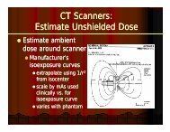
RSMI 2009 Session III<br />
Diagnostic X-Ray <strong>Shielding</strong> Design<br />
<strong>NCRP</strong>-<strong>147</strong> <strong>Shielding</strong> <strong>Models</strong><br />
Douglas J. Simpkin, Ph.D.<br />
Aurora St. Luke’s Medical Ctr<br />
Milwaukee, WI<br />
dsimpkin@wi.rr.com<br />
http://www.geocities.com/djsimpkin/
<strong>Models</strong> for Diagnostic X-Ray<br />
<strong>Shielding</strong> Calculations<br />
Yes<br />
No<br />
2
The Three <strong>Models</strong> for Diagnostic<br />
X-ray <strong>Shielding</strong> In <strong>NCRP</strong> <strong>147</strong><br />
1. First-principle extensions to <strong>NCRP</strong> 49<br />
2. Given calculated kerma per patient, scale<br />
by # patients and inverse squared distance,<br />
and then use transmission curves designed<br />
for particular room types<br />
3. NT/(Pd 2 )<br />
3
1 st principle extensions to <strong>NCRP</strong> 49<br />
• (Underlies the other two methods)<br />
• The kerma in the occupied area may have<br />
contributions from<br />
– primary radiation<br />
– scatter radiation<br />
}<br />
– leakage radiation } Secondary radiation<br />
4
Primary, Scatter, and Leakage<br />
Must protect<br />
from primary<br />
radiation<br />
primary<br />
Must protect from<br />
scatter & leakage<br />
radiation<br />
5
1 st principle extensions to <strong>NCRP</strong> 49<br />
• The models for primary, scatter, and leakage in<br />
<strong>NCRP</strong>-<strong>147</strong> are extensions to what’s in <strong>NCRP</strong>-<br />
49 (1976):<br />
– x-ray tubes operating over ranges of potentials<br />
(“workload distribution”)<br />
– new model for image receptor attenuation<br />
– new model for leakage<br />
6
1 st principle extensions to <strong>NCRP</strong> 49<br />
• These primary, scatter, and leakage<br />
radiations may be from multiple x-ray<br />
sources (or tube positions)<br />
• So, simply add up all the contributions to the<br />
kerma, K, from all these sources in the<br />
occupied area behind a barrier of thickness x,<br />
K ( x)<br />
= ( K ( x)<br />
+ K ( x)<br />
K ( x)<br />
)<br />
∑ ∑ +<br />
tubes kVp<br />
P<br />
S<br />
L<br />
7
1 st principle extensions to <strong>NCRP</strong> 49<br />
• Then iteratively find a barrier thickness x that<br />
decreases that kerma to P/T, the design goal<br />
modified by the occupancy factor<br />
K )<br />
(<br />
x<br />
) =<br />
∑ ∑ ( K<br />
(<br />
x<br />
)<br />
+<br />
K<br />
(<br />
x<br />
)<br />
+<br />
K<br />
(<br />
x<br />
)<br />
=<br />
= P<br />
S<br />
L<br />
tubes kVp<br />
• See http://www.geocities.com/djsimpkin/ for<br />
shareware program XRAYBARR to do this<br />
P<br />
T<br />
8
1 st principle extensions to <strong>NCRP</strong> 49<br />
• XRAYBARR was written by me in the mid<br />
1990s to perform shielding calculations with<br />
these new models as we developed <strong>NCRP</strong>-<strong>147</strong>.<br />
The shielding data and examples in <strong>NCRP</strong>-<strong>147</strong><br />
are based on the output of XRAYBARR.<br />
• Note: Some of the examples in <strong>NCRP</strong>-<strong>147</strong><br />
aren’t duplicated by XRAYBARR because<br />
<strong>NCRP</strong>-<strong>147</strong> takes shortcuts in the tabulated x pre<br />
values. XRAYBARR is right!<br />
9
Primary <strong>Radiation</strong> Model<br />
• In primary beam,<br />
know kerma per<br />
workload at 1 m,<br />
K W(kVp) , for 3<br />
phase units (data<br />
of Archer et al.<br />
1994)<br />
Primary Kerma at 1 m per workload<br />
10
Unshielded Primary Beam Kerma<br />
KW ( kVp<br />
) W<br />
( kVp<br />
)<br />
K (0)<br />
=<br />
d<br />
W<br />
• At a given kVp,<br />
P<br />
2<br />
• If only a fraction U of the tube’s workload<br />
is directed at this barrier, then<br />
K<br />
K ( 0) =<br />
W<br />
P<br />
( kVp)<br />
d<br />
2<br />
P<br />
P<br />
U W ( kVp)<br />
• U is the use factor for this barrier<br />
11
Kerma Behind a Primary Barrier<br />
• The kerma behind a primary barrier of<br />
transmission B(x, kVp) is<br />
K<br />
K<br />
kVp<br />
U W<br />
kVp<br />
(<br />
) (<br />
)<br />
( x,<br />
kVp)<br />
W<br />
B<br />
( x,<br />
kVp<br />
)<br />
2<br />
d<br />
P =<br />
• For the whole distribution of workloads, total<br />
kerma is<br />
P<br />
K<br />
P<br />
( x)<br />
=<br />
∑<br />
kVp<br />
K<br />
W<br />
( kVp)<br />
U W<br />
2<br />
d P<br />
( kVp)<br />
B(<br />
x,<br />
kVp)<br />
12
Primary <strong>Radiation</strong>:<br />
i<br />
The Old <strong>NCRP</strong>-49 Model<br />
x<br />
Barrier of thickness x decreases raw<br />
primary radiation kerma to P/T<br />
13
Primary <strong>Radiation</strong>:<br />
The Reality<br />
Grid, cassette,<br />
supporting structures<br />
patient<br />
t<br />
Primary radiation is significantly<br />
attenuated t before reaching barrier<br />
14
Primary <strong>Radiation</strong>:<br />
A Conservative, Realistic Model<br />
Grid, cassette, maybe<br />
image receptor<br />
supporting structures<br />
Even without the patient, primary radiation is still<br />
significantly ifi attenuated t before reaching barrier<br />
15
Primary <strong>Radiation</strong>:<br />
<strong>NCRP</strong>-<strong>147</strong> Model<br />
Grid, cassette, maybe<br />
supporting structures<br />
No patient!<br />
t!<br />
x pre<br />
} x tot = x + x pre<br />
x<br />
Assume primary beam attenuation in image receptor is due to a<br />
pseudo-barrier whose equivalent thickness x pre gives same<br />
transmission as that seen for actual image receptors.<br />
16
1E+0 Primary Transmission Through Patient,<br />
8<br />
6 Image Receptor, and Supports<br />
4<br />
Data of Dixon (1994)<br />
Transmiss sion<br />
1E-1<br />
2<br />
8<br />
6<br />
4<br />
2<br />
1E-2<br />
8<br />
6<br />
1E-3<br />
4<br />
2<br />
8<br />
6<br />
4<br />
2<br />
1E-4<br />
No patient & grid & cassette:<br />
B = 4.7E-6 kVp 2.181<br />
No patient & grid & cassette &<br />
cassette support structures &<br />
radiographic table:<br />
B = 9.36E-13 kVp 4.917<br />
ers<br />
Wall-Mou unted Grid +<br />
Cassette + Cassette Hold<br />
Type of Radiographic Table<br />
(data of Dixon 1994)<br />
GE RTE Table<br />
GE Advantx Table<br />
Siemens Multix-T Table<br />
Picker Clinix-T Table<br />
40 50 60 70 80 90 100 125 150<br />
kVp<br />
17
1E+3<br />
Values of x pre<br />
(Grid+cassette+support)<br />
p<br />
Gypsum<br />
1E+2 Plate Glass<br />
Concrete<br />
x pre (mm m)<br />
1E+1<br />
Steel<br />
1E+0<br />
Lead<br />
1E-1<br />
1<br />
20 30 40 50 60 70 80 90 100 110 120 130 140 150<br />
kVp<br />
18
x pre for Radiographic Room<br />
Workload Distributions<br />
• From <strong>NCRP</strong>-<strong>147</strong> Table 4.6:<br />
– Grid + cassette:<br />
• 0.3 mm Pb<br />
• 30 mm concrete<br />
– Gid+ Grid cassette +tbl/h table/chest tbucky supports:<br />
• 0.85 mm Pb<br />
• 72 mm concrete<br />
• (See Dixon & Simpkin Health Phys 74;181-<br />
189;1998 for a more complete list.)<br />
19
Calculation of Primary Kerma<br />
• Same as model in <strong>NCRP</strong>-49 except<br />
– account for workload distribution in kVp<br />
– May account for image receptor shielding x pre<br />
• Primary kerma in occupied area is then<br />
K ( x )<br />
P<br />
1<br />
d 2<br />
P<br />
+ x pre<br />
=<br />
∑ K W ( kVp)<br />
U W ( kVp)<br />
B(<br />
x + x pre , kVp)<br />
kVp<br />
20
Scatter <strong>Radiation</strong><br />
patient<br />
21
Scaled Normalized Scatter Fraction<br />
1 m<br />
1 m<br />
1m<br />
K S<br />
K P<br />
1 cm 2 area<br />
primary beam<br />
at 1 m<br />
θ<br />
K<br />
a<br />
′ =<br />
S<br />
× 10 +6<br />
1<br />
K<br />
P<br />
22
Scaled Normalized Scatter Fraction<br />
'<br />
23
Scatter <strong>Radiation</strong><br />
• Same theory as old <strong>NCRP</strong>-49<br />
K<br />
– scatter fraction data of Kelley & Trout reevaluated<br />
by Simpkin & Dixon (Health Phys 1998)<br />
– pri ib beam area F (cm 2 ) measured at pri idistance d F<br />
conveniently taken as image receptor area @ SID<br />
– explicitly itl show kVp dependence d and sum over<br />
workload distribution to yield shielded scatter<br />
kerma<br />
S<br />
−6<br />
a′<br />
× 10 K ( ) ( )<br />
,<br />
1 W<br />
kVp W kVp F<br />
( x θ ) =<br />
∑<br />
B<br />
( x,<br />
kVp<br />
)<br />
2 2<br />
d<br />
d<br />
kVp<br />
S<br />
F<br />
24
Leakage <strong>Radiation</strong><br />
<strong>Radiation</strong> originating from x-<br />
ray tube focal spot but not<br />
emanating from the tube<br />
portal<br />
patient<br />
25
Leakage radiation<br />
• Intensity can’t exceed L = 100 mR/hr at 1 m<br />
when tube is operated at its leakage<br />
technique factors<br />
– maximum potential for continuous operation<br />
kVp max (typically 135-150150 kVp, or 50 kVp for<br />
mammography)<br />
– I max is the maximum continuous tube current<br />
possible at kVp max . Note that this is usually a<br />
low mA, not typical of clinical radiography.<br />
26
Leakage radiation<br />
• These leakage technique factors specify<br />
how thick the shielding in the tube housing<br />
should be<br />
• <strong>NCRP</strong>49 suggested leakage technique<br />
factors of 3.3 mA at 150 kVp, 4 mA at 125<br />
kVp, 5 mA at 100 kVp; remain fairly<br />
typical today<br />
27
Leakage radiation<br />
• <strong>NCRP</strong>-<strong>147</strong> calculations (and shielding methods<br />
2 and 3) use<br />
– 3.33 mA at 150 kVp<br />
– worst case leakage rates<br />
– (Subsequently, we’ve found that assuming 4 mA at<br />
125 kVp leakage technique factors specifies<br />
barriers that are 10-20% thicker than in the report)<br />
– However, actual leakage rates are 0-30% of the<br />
maximum leakage so we don’t see a problem<br />
28
New Leakage Model<br />
• For tube operating at techniques (kVp, I) with<br />
transmission through the tube housing B housing ,<br />
assume leakage kerma rate at 1 m through tube<br />
housing is<br />
2<br />
K<br />
L ( h i<br />
( kVp<br />
)<br />
∝<br />
kVp<br />
I<br />
Bhousing (<br />
kVp<br />
)<br />
• Assume worst case scenario: leakage kerma rate =<br />
limit L for tube operation at leakage technique<br />
factors (conservative by factors of 3 to ~infinity)<br />
29
New Leakage Model<br />
• Estimate thickness of tube housing by using primary beam<br />
output at leakage technique factors as model for unhoused<br />
leakage radiation.<br />
1931 mGy/hr 100 mR/hr = 0.873 mGy/hr<br />
1 m<br />
Tube operated at<br />
150 kVp, 3.3 mA<br />
1 m<br />
“unhoused”<br />
tube<br />
Tube housing<br />
= 2.32 mm Pb<br />
thick<br />
1 m 1 m<br />
1931 mGy/hr 1931 mGy/hr<br />
30
New Leakage Model<br />
• Write ratio of leakage kerma rates at any kVp<br />
to L at kVp max<br />
• and knowing that at a given kVp, workload<br />
W(kVp) is the time integral of the tube<br />
current: W ( kVp)<br />
= ∫ I dt<br />
•then unshielded d leakage kerma K L (at 1 m) at<br />
that kVp is<br />
K L<br />
(0, kVp)<br />
=<br />
L kVp<br />
2<br />
(1 −U<br />
) W<br />
2<br />
( kVp)<br />
B<br />
housing<br />
kVp I<br />
B<br />
( housing max )<br />
max max<br />
kVp<br />
( kVp)<br />
31
New Leakage Model<br />
• Applying inverse square to distance d L from<br />
tube to shielded area,<br />
• and putting a barrier with transmission<br />
exp(–ln(2)x/HVL) between tube & area yields<br />
K L<br />
( x,<br />
kVp)<br />
=<br />
L kVp<br />
1<br />
d<br />
2<br />
d L<br />
2<br />
kVp<br />
(1 −<br />
U<br />
)<br />
W<br />
2<br />
max<br />
I<br />
max<br />
(<br />
kVp<br />
)<br />
B<br />
⎛ − ln(2) x<br />
× exp⎜<br />
⎝ HVL(kVp(<br />
)<br />
housing<br />
⎞<br />
⎟<br />
⎠<br />
B<br />
housing<br />
( kVp<br />
max<br />
(<br />
kVp<br />
)<br />
×<br />
)<br />
32
How far off is <strong>NCRP</strong>-49’s leakage model<br />
1E+0<br />
1E-1<br />
1E-2<br />
<strong>NCRP</strong>-1 <strong>147</strong> leakage e/<br />
<strong>NCRP</strong>-4 49 leakage<br />
1E-3<br />
1E-4<br />
Leakage dose as function of kVp<br />
transmitted through x-ray tube<br />
1E-5 housing of 2.32 mm Pb compared<br />
to that at 150 kVp<br />
1E-6<br />
1E-7<br />
Leakage technique factors:<br />
150 kVp, 3.3 mA for 100 mR/hr<br />
1E-8<br />
1E-9<br />
50 60 70 80 90 100 110 120 130 140 150<br />
kVp<br />
33
Summary: <strong>Shielding</strong> Model No. 1<br />
• Rigorous model based on the well-accepted<br />
<strong>NCRP</strong>-49 methods.<br />
• But you need a computer program<br />
(XRAYBARR, for example) to implement<br />
fully!<br />
• Is there a shielding method that allows<br />
paper and calculator solutions<br />
34
<strong>NCRP</strong>-<strong>147</strong> <strong>Shielding</strong> Model No. 2<br />
• For each clinical workload distribution, of<br />
total workload dWW norm per patient, for both<br />
primary and secondary barriers, <strong>NCRP</strong>-<strong>147</strong><br />
provides:<br />
– K 1 , the kerma per patient at 1 m distance<br />
• Primary kerma per patient K 1 P is in Table 4.5<br />
• Secondary kerma per patient K sec1 is in Table 4.7<br />
– B, the transmission of the radiation<br />
generated by this workload distribution for<br />
primary or secondary barriers (cf App B & C)<br />
35
<strong>NCRP</strong>-<strong>147</strong> <strong>Shielding</strong> Model No. 2<br />
Primary Air Kerma at 1 m for Workload<br />
Distributions, ib i K 1<br />
36
<strong>NCRP</strong>-<strong>147</strong> <strong>Shielding</strong> Model No. 2<br />
Secondary Air Kerma at 1 m for Workload<br />
Distributions, K 1 sec<br />
37
<strong>NCRP</strong>-<strong>147</strong> <strong>Shielding</strong> Model No. 2<br />
• For single kVp operation cf. Simpkin and<br />
Dixon Health Phys. 74(3), (), 350–365 for<br />
secondary kerma per workload at 1 m at<br />
single kVp operation<br />
• All other data is available in <strong>NCRP</strong> <strong>147</strong><br />
– But be careful reading scientific notation:<br />
1.234 x 10 1 = 12.34<br />
38
<strong>Shielding</strong> Model No. 2<br />
• Get the unshielded kerma, K(0), by scaling the kerma<br />
per patient at 1 m, K 1 , by<br />
– N patient procedures (suggested values of N are in Table<br />
4.3) or, equivalently<br />
– total workload W tot (where workload/pat = W norm )<br />
– can tweak W tot by a QE-specified different workload per<br />
patient, W site<br />
• Kerma is then<br />
1<br />
K<br />
U N<br />
K( 0) = =<br />
2<br />
d<br />
K<br />
– (where U is replaced dby 1 for secondary barriers)<br />
d<br />
1<br />
2<br />
U W<br />
W<br />
tt tot<br />
norm<br />
39
<strong>Shielding</strong> Model No. 2<br />
• Ratio of P/T to K(0) is the required transmission<br />
2 2<br />
P / T P d P d W<br />
B<br />
( x<br />
) = = =<br />
norm<br />
K<br />
(0)<br />
1<br />
1<br />
N T UD W T UD<br />
– (again, U is replaced by 1 for secondary barriers)<br />
• Transmission i B is now a function of<br />
– barrier material and thickness<br />
– workload distribution<br />
ib i<br />
– primary or secondary<br />
tot<br />
40
B=0.0047<br />
x=1.2 mm Pb<br />
42
Now the<br />
difficulty is in<br />
reading the<br />
correct curve!<br />
43
<strong>Shielding</strong> Model No. 3 for<br />
“Representative Rooms”<br />
• Model No. 2 fails for<br />
complicated<br />
assemblages of x-ray<br />
tubes/ positions/<br />
workload<br />
distributions, such as<br />
in a radiographic or<br />
radiographic/<br />
fluoroscopic room<br />
44
<strong>Shielding</strong> Model No. 3 for<br />
“Representative Rooms”<br />
• (Using XRAYBARR) <strong>NCRP</strong>-<strong>147</strong> shows<br />
barrier thickness requirements calculated for<br />
representative rooms:<br />
– Assume conservatively small room layout<br />
• assures maximum contribution from all sources<br />
– Presumes that the kinds of exposures made<br />
amongst the various x-ray tubes/positions follow<br />
those observed by the AAPM TG-9 survey<br />
45
Representative Radiographic Room<br />
46
Use Factors from AAPM Survey<br />
Rad Room:<br />
Chest Bucky<br />
(Another primary wall gets<br />
U=2% of the floor/ other<br />
barrier distribution; assume<br />
tube is centered overtable)<br />
Cross-table<br />
Lateral Position<br />
U=9%<br />
Overtable Position<br />
U=89% shooting down<br />
at tfloor<br />
Rad Room: floor/<br />
other barriers applies<br />
to Overtable and<br />
Crosstable positions<br />
47
Representative Radiographic Room<br />
Chest<br />
Bucky<br />
wall<br />
primary<br />
Secondary Barrier<br />
ky<br />
dary<br />
est Buck<br />
l second<br />
Che<br />
wal<br />
Cross-table<br />
Lateral Wall<br />
primary<br />
Secondary Barrier<br />
U=2%<br />
primary<br />
wall<br />
48
“Representative R&F Room”<br />
• Also assume a “Representative R&F room”<br />
– Has same layout as “Standard Radiographic Room<br />
except an undertable fluoro x-ray tube and image<br />
intensifier are added, centered over table<br />
– Does fluoro as well as standard radiographic work,<br />
with table and chest buckies and crosstable work<br />
• Assume<br />
– 75% of patients imaged as if in radiographic room<br />
– 25% of patients imaged by fluoroscopy tube<br />
49
“Representative R&F Room”<br />
Chest Rad<br />
tube<br />
Overtable<br />
Rad tube<br />
Image<br />
Intensifier<br />
Crosstable<br />
Lateral Rad<br />
Tube<br />
Undertable Fluoro Tube<br />
50
“Representative Room”<br />
Barrier Requirements<br />
• From Model 2, transmission requirement is<br />
B ( x)<br />
=<br />
2<br />
P d<br />
N T UK<br />
1<br />
• so the barrier thickness requirement must<br />
scale as:<br />
N T<br />
P d<br />
2<br />
51
• Method:<br />
“Representative Room”<br />
Barrier Requirements<br />
– Given N patients/week, need to shield to P/T, a<br />
distance d from the x-ray source<br />
N T<br />
P d<br />
– Calculate in mGy -1 m -2<br />
2<br />
– Look up the required barrier thickness on the<br />
graph appropriate for that workload<br />
distribution, barrier, and barrier material<br />
52
There are 12 NT/Pd 2 graphs<br />
2<br />
• For Representative Radiographic and R&F<br />
Rooms:<br />
–For Lead and Concrete:<br />
• Primary barriers with preshielding<br />
• Primary barriers without preshielding<br />
• Secondary barriers<br />
53
NT/Pd 2 curves have been fit<br />
•The NT/Pd 2 curves have been fit to a<br />
modified Archer eqn:<br />
• See fitting parameters at<br />
– http://geocities.com/djsimpkin/<strong>Shielding</strong>/Shield<br />
ing.htm<br />
55
NT/Pd 2 : From where is d<br />
Primary Barriers<br />
measured<br />
Floor<br />
overhead radiographic tube<br />
Chest Bucky wall<br />
chest tube (72" SID)<br />
Crosstable Lateral Wall cross-table tube (40" SID)<br />
2% U wall center of table<br />
Secondary Barriers<br />
Floor<br />
Chest Bucky secondary wall<br />
Secondary Wall<br />
Ceiling<br />
patient on table<br />
chest tube (72" SID)<br />
patient on table<br />
patient on table<br />
57
Equivalency of <strong>Shielding</strong> Materials for<br />
Model No. 3 Calculations<br />
• For “representative room” calculations only,<br />
conservatively conclude<br />
– Steel thickness requirement =<br />
8 × Pb thickness requirement<br />
– Gypsum wallboard thickness requirement =<br />
3.2 × concrete thickness requirement<br />
– Glass thickness requirement =<br />
1.2 × concrete thickness requirement<br />
58
Conclusions<br />
• <strong>NCRP</strong>-<strong>147</strong> utilizes 3 shielding models<br />
– Model No. 1: Extension of the methods of <strong>NCRP</strong>-49<br />
• With kVp dependence<br />
• With new models for primary and leakage<br />
• Requires computer program to implement tfully<br />
– Model No. 2: Based on data from model no. 1,<br />
• <strong>NCRP</strong>-<strong>147</strong> shows kerma per patient at 1 m and transmission<br />
curves appropriate for a given workload.<br />
• Calculate unshielded kerma and then transmission needed to<br />
reduce to P/T. Look up barrier thickness.<br />
– Model lNo. 3: Based on data from model no. 1,<br />
• For N patients at distance d (for a particular workload<br />
distribution & barrier), calculate NT/Pd 2<br />
• <strong>NCRP</strong>-<strong>147</strong> shows barrier thickness as function of NT/Pd 2<br />
59