VSL Technical Report.. - Free
VSL Technical Report.. - Free
VSL Technical Report.. - Free

Create successful ePaper yourself
Turn your PDF publications into a flip-book with our unique Google optimized e-Paper software.
<strong>VSL</strong><br />
CONCRETE<br />
STORAGE STRUCTURES<br />
USE OF THE <strong>VSL</strong> SPECIAL<br />
CONSTRUCTION METHODS<br />
MAY 1983<br />
<strong>VSL</strong> INTERNATIONAL LTD.<br />
Berne / switzerland
Table of contents<br />
Page<br />
Foreword 1<br />
1. Applicable <strong>VSL</strong> systems 1<br />
1.1. Introduction 1<br />
1.2. <strong>VSL</strong> Slipforming 1<br />
1.3. <strong>VSL</strong> Post-tensioning 2<br />
1.4. <strong>VSL</strong> Heavy Rigging 4<br />
1.5. Reference to other <strong>VSL</strong> systems 4<br />
1.6. Services offered by <strong>VSL</strong> 4<br />
2.5. Safety walls 31<br />
2.5.1. Introduction 31<br />
2.5.2. Safety wall for ammonia tank, Hopewell, USA 31<br />
2.5.3. Safety wall for ethylene tank, Australia 31<br />
2.5.4. Safety walls for gasoline tanks, Lalden, Switzerland 32<br />
2.5.5. Safety wall for oil tank, Vienna, Austria 33<br />
2.6. <strong>VSL</strong>fuel oil tank 34<br />
2. Storage tanks for liquids 5<br />
2.1. Water tanks 5<br />
2.1.1. Introduction 5<br />
2.1.2. Water tank, Willows, USA 5<br />
2.1.3. Water tank, Paarl, South Africa 6<br />
2.1.4. Water tank, Buraydah, Saudi Arabia 7<br />
2.1.5. Water tank, Barnarp, Sweden 8<br />
2.1.6. Water tank, Leigh Creek South, Australia 8<br />
2.1.7. Water tank, Aqila, Kuwait 9<br />
2.1.8. Water tanks, Dodoma, Tanzania 9<br />
2.2. Water towers 11<br />
2.2.1. Introduction 11<br />
2.2.2. Water tower, Leverkusen, FR Germany 11<br />
2.2.3. Roihuvuori Water Tower, Helsinki, Finland 13<br />
2.2.4. Water and Telecommunications Tower Mechelen,<br />
Belgium 14<br />
2.2.5. Water tower, Buraydah, Saudi Arabia 16<br />
2.2.6. Water tower, AI Kharj, Saudi Arabia 17<br />
2.2.7. Water tower, Bandung, Indonesia 18<br />
2.2.8. Water towers for the new railway stations at Riyadh,<br />
Hofuf and Dammam, Saudi Arabia 20<br />
2.3. Sewage tanks 21<br />
2.3.1. Introduction 21<br />
2.3.2. Sludge digestion tanks, Prati Maggi, Switzerland 21<br />
2.3.3. Sewage treatment plant, Groningen-Garmerwolde,<br />
Netherlands 21<br />
2.3.4. Sludge tanks, Linz-Asten, Austria 23<br />
2.3.5. Sludge digestion tanks, Los Angeles, USA 25<br />
2.3.6. Environmental protection tanks 26<br />
2.4. LNG and LPG Storage tanks 27<br />
2.4.1. Introduction 27<br />
2.4.2. Tanks at Montoir, France 27<br />
2.4.3. Tanks at Terneuzen, Netherlands 28<br />
2.4.4. Fife Ethylene Plant, Great Britain 28<br />
2.4.5. Tanks at Antwerp, Belgium 29<br />
3. Tanks for the storage of solids (silos) 35<br />
3.1. Cement and clinker silos 35<br />
3.1.1. Introduction 35<br />
3.1.2. Clinker silos, Pedro Leopoldo, Brazil 35<br />
3.1.3. Cement silos, Chekka, Lebanon 35<br />
3.1.4. Clinker silos, Wetzlar, FR Germany 37<br />
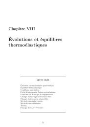
3.1.5. Clinker silos, Rombas, France 37<br />
3.1.6. Cement silos, Slite, Sweden38<br />
3.1.7. Cement and clinker silos at Cibinong, Indonesia 38<br />
3.1.8. Clinker silo, Exshaw, Canada 40<br />
3.2. Tanks for other solid materials 41<br />
3.2.1. Alumina silos, Portoscuso, Italy 41<br />
3.2.2. Alumina and coke silo, Richards Bay, South Africa 42<br />
3.2.3. Sugar silo, Enns, Austria 43<br />
3.2.4. Sugar silo, Frauenfeld, Switzerland 43<br />
3.2.5. Flour and grain silos, Kuwait 44<br />
3.2.6. Ore silo, Grangesberg, Sweden 45<br />
3.2.7. Coal silos, Gillette, Wy., USA 46<br />
4. Repairs 47<br />
4.1. Introduction 47<br />
4.2. Cement silos, Linz, Austria 47<br />
4.3. Sludge digestion tank, Meckersheim, FR Germany 47<br />
5. Bibliography and references 48<br />
5.1. Bibliography 48<br />
5.2. References 48<br />
Copyright 1983 by<br />
<strong>VSL</strong> INTERNATIONAL LTD., Berne/Switzerland<br />
All rights reserved<br />
Printed in Switzerland
CONCRETE STORAGE STRUCTURES - USE OF THE <strong>VSL</strong> SPECIAL CONSTRUCTION<br />
METHODS<br />
Foreword<br />
Tanks fulfil an important role in supplying mankind<br />
with essential products. They are used for storing<br />
liquids or solids which may be either intermittently<br />
produced but consumed at a fairly uniform rate, or<br />
continuously produced at a fairly uniform rate but<br />
consumed in an irregular manner. A further<br />
important aspect is that the locations of origin and<br />
consumption are frequently appreciable distances<br />
apart. These circumstances necessitate the<br />
provision of appropriate storage capacities.<br />
The building of tanks in concrete offers several<br />
advantages:<br />
- Concrete tanks are economical to construct<br />
and maintain (they require virtually no mainte<br />
nance). Construction is relatively inexpensive<br />
because the basic materials for making<br />
concrete are usually locally available and sui<br />
table special building methods make rapid<br />
construction possible.<br />
-Concrete tanks are relatively insensitive to<br />
mechanical influences, whereas steel tanks,<br />
for example, when used for storing environ<br />
mentally polluting or dangerous substances<br />
have to be surrounded by protective concrete<br />
walls to assure the required degree of safety.<br />
-Concrete tanks are eminently suitable for the<br />
storing of a very wide variety of substances;<br />
for example, if provided with a suitable liner,<br />
they may even be used for low temperature<br />
liquefied gases.<br />
The present report, which comprises descriptions<br />
of more than forty completed tank structures, has<br />
been prepared with the objective of illustrating the<br />
advantages of concrete tanks, of providing a<br />
summary of the numerous possible applications,<br />
and of explaining what <strong>VSL</strong> special construction<br />
methods can be employed in the building of<br />
concrete tanks and when, where and how these<br />
methods may be used. Since<br />
the type of substance to be stored has a profound<br />
influence upon the form and construction of a<br />
tank, the descriptions have been placed in<br />
appropriate chapters and usually arranged in<br />
chronological order. This will facilitate a certain<br />
degree of comparison within each group, though it<br />
must be remembered that the design conditions<br />
can vary appreciably on account of the differences<br />
in national codes and standards.<br />
The <strong>VSL</strong> organizations will be pleased to assist<br />
and advise you on questions relating to tank construction<br />
and hope that the present report will be<br />
helpful to you by stimulating new ideas, providing<br />
some pointers and offering possible solutions.<br />
The <strong>VSL</strong> Representative in your country or <strong>VSL</strong><br />
INTERNATIONAL LTD., Berne, Switzerland will<br />
be glad to provide you with further information on<br />
the subject of «Concrete tanks» or on the <strong>VSL</strong><br />
special construction methods.<br />
1. Applicable <strong>VSL</strong><br />
1.1 Introduction<br />
In tank construction three <strong>VSL</strong> special systems<br />
are of particular importance:<br />
- <strong>VSL</strong> Slipforming,<br />
- <strong>VSL</strong> Post-tensioning,<br />
- <strong>VSL</strong> Heavy Rigging.<br />
These systems ar1.e generally used in the above<br />
sequence, a tank being first built with the<br />
assistance of slipforming and then prestressed,<br />
after which, in certain circumstances, the tank<br />
itself of some other component, such as the roof,<br />
is brought into an elevated position.<br />
In principle, the systems are used separately, but<br />
it is especially advantageous if <strong>VSL</strong> is chosen for<br />
all the systems. By making use of the various <strong>VSL</strong><br />
systems in combination and taking account of this<br />
possibility at an early stage in planning, the Client<br />
will obtain substantial advantages. These may<br />
include, for example:<br />
- The placing of the cable fixings and ducts during<br />
the slipforming operation is carried out<br />
simultaneously with the fixing of reinforcement<br />
and can be continually monitored by the <strong>VSL</strong><br />
slipforming personnel.<br />
- The formwork panels, to which the <strong>VSL</strong><br />
anchorages are fixed at the buttresses, are<br />
reused during slipforming.<br />
- Lifting cables can be converted into suspension<br />
cables and the latter can then be post-tensioned.<br />
- The preparatory work, progress and also the use<br />
of personnel and materials are all<br />
under one control, which considerably simplifies<br />
coordination.<br />
1.2. <strong>VSL</strong> Slipforming<br />
Tanks at or near ground level and the shafts of<br />
water towers are especially well suited to the use<br />
of slipforming during building, since the<br />
preconditions for economic use of this<br />
construction method exist to a particularly high<br />
degree in these structures:<br />
- The proportion of walls to the total structure is<br />
high.<br />
- The shape and dimensions of the structure<br />
usually remain unchanged throughout the<br />
height.<br />
- The number of openings, built-in items, reces<br />
ses etc. is small.<br />
- Large structures can be built by steps or<br />
segments.<br />
- Insulation can be installed during building of the<br />
walls.<br />
The advantage of slipforming include the short<br />
construction time resulting from continuous<br />
working, monolithic construction without<br />
construction joints and of high dimensional<br />
accuracy and cost savings even where the height<br />
is moderate.<br />
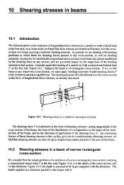
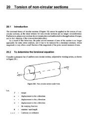
The slipforms of the <strong>VSL</strong> Slipforming consist of<br />
1.25 m high elements of steel. They are<br />
standardized components, from which any desired<br />
plan form can be made up. Steel was<br />
chosen as the formwork material because it<br />
guarantees the highest dimensional accuracy in<br />
construction. The inner and outer forms are<br />
connected together by transverse yokes. At the<br />
upper edge of the forms, working platforms are<br />
located and scaffolds for finishing the concrete<br />
surface are suspended beneath them.<br />
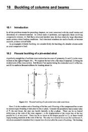
Figure 1: Basic construction of <strong>VSL</strong><br />
Slipforming<br />
1
Figure 3: Stressing anchorage <strong>VSL</strong>type E<br />
Figure 4: Stressing anchorage <strong>VSL</strong> type EC<br />
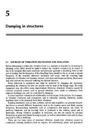
Figure 2 The use of <strong>VSL</strong> Slipforming in thank construction<br />
Figure 5: Centre stressing anchorage <strong>VSL</strong><br />
type Z<br />
The forms are raised by hydraulic jacks of 30 or<br />
60 kN lifting force moving on jacking tubes. The<br />
jacking tubes are positioned inside the wall under<br />
construction and transfer the load from the<br />
formwork equipment to the foundation. In the wet<br />
concrete zone the jacking tubes are encased in<br />
ducts which are connected to the slipform. These<br />
ducts provide antibuckling guidance to the tubes<br />
and prevent them from being concreted in, so that<br />
they can be recovered and used again (Fig. 1).<br />
<strong>VSL</strong> Slipforming can also be used with special<br />
forms, by which conical walls and walls of variable<br />
thickness or special shapes can be produced. The<br />
speed of progress depends upon many factors,<br />
such as size of structure, dimensions,<br />
reinforcement, concrete quality, temperature etc.<br />
The rate varies from 2 to 6 m per 24 hours.<br />
Slipforming is a largely mechanized construction<br />
procedure. A trouble-free and therefore economic<br />
sequence of work requires certain preconditions<br />
in respect of design, organization and<br />
construction. Cooperation should therefore be<br />
established as early as possible between the<br />
project designer, main contractor and slipforming<br />
contractor. This will then guarantee rational and<br />
coordinated construction.<br />
Information about the use of <strong>VSL</strong> Slipforming in<br />
the building of tanks and water towers (Fig. 2) will<br />
be found in the following chapters. Attention is<br />
also drawn to the publication «<strong>VSL</strong> Slipforming»,<br />
which contains further details and examples of<br />
use.<br />
1.3. <strong>VSL</strong> Post-tensioning<br />
Post-tensioning is used in tank construction for<br />
the following reasons:<br />
- It provides the required resistance to the acting<br />
forces.<br />
- It makes possible solutions more economic<br />
than those achievable with reinforced concrete<br />
or steel.<br />
- It renders the concrete virtually free of cracks.<br />
The <strong>VSL</strong> Post-tensioning System (see publication<br />
«<strong>VSL</strong> Post-tensioning» with its wide variety of<br />
types of anchorage and cable units, is ideally<br />
suited for use in tank construction. The methods<br />
adopted for assembling the tendons are also of<br />
particular advantage in tank construction, since<br />
they can be adapted to the particular<br />
circumstances encountered.<br />
The <strong>VSL</strong> Post-tensioning System uses, as tension<br />
elements, only 7-wire strands of 13 mm (0.5"), 15<br />
mm (0.6") or 18 mm (0.7") nominal diameter, with<br />
ultimate tensile strengths of 1670 to 1860 N/mm 2 .<br />
In addition to the high strength and low relaxation,<br />
the great ease with which the strands may be<br />
grouted (due to the screw action) should be<br />
emphasized. The strands of the <strong>VSL</strong> cables are<br />
stressed simultaneously, but individually locked in<br />
the anchorage. Stressing can be carried out in as<br />
many steps as desired.<br />
In tank construction, the <strong>VSL</strong> Post-tensioning can<br />
provide the stressing anchorages types E and EC<br />
(Figures 3 and 4), which are installed in buttresses,<br />
Figure 6: Centre stressing anchorage <strong>VSL</strong><br />
type ZU<br />
are installed in buttresses, and also the special<br />
centre stressing anchorages types Z and ZU<br />
(Figures 5 and 6), which make the provision of<br />
buttresses unnecessary as these anchorages can<br />
be stressed in a block-out in the wall. Of the<br />
dead-end anchorages, apart from types H and U<br />
(Figures 7 and 8), special mention should be<br />
made of type L, in which the tendon can be returned<br />
through 180° in a small space. This type is<br />
especially suitable for vertical post-tensioning,<br />
since it enables the posttensioning steel to be<br />
installed later, which has constructional<br />
advantage (Fig. 9).<br />
The horizontal tendons also are usually installed<br />
after concreting. The <strong>VSL</strong> pushthrough method is<br />
most commonly used here; this consists of pulling<br />
the strand from the dispenser and pushing it by<br />
means of a special device directly into the duct.<br />
When the strand has reached the necessary<br />
length it is cut off and the procedure is repeated<br />
2
Figure 7: Dead-end anchorage <strong>VSL</strong> type H<br />
Figure 8: Dead-end anchorage <strong>VSL</strong> type U<br />
Figure 8: Dead-end anchorage <strong>VSL</strong> type U<br />
Figure 10: Diagrammatic representation of<br />
the <strong>VSL</strong> push-through equipment<br />
until all the strands of the cable have been placed<br />
in the duct (Fig. 10). In tank construction, the<br />
following possible applications of post-tensioning<br />
may be considered:<br />
- Post-tensioning of foundation slabs,<br />
- Longitudinal post-tensioning of straight walls,<br />
- Circumferential post-tensioning of walls,<br />
- Vertical post-tensioning of walls,<br />
- Post-tensioning of flat tank roofs,<br />
- Post-tensioning of tank shells,<br />
- Suspension of tank shells.<br />
In foundation slabs, the crack-free nature of the<br />
structure obtained and economic savings are<br />
decisive advantages favouring the use of<br />
post-tensioning. Especially in the case of tanks of<br />
large horizontal dimensions, post-tensioned<br />
foundation slabs are cheaper than ordinarily<br />
reinforced slabs, since less material is required.<br />
The tendons are usually arranged orthogonally,<br />
even for circular foundation slabs.<br />
For straight walls, post-tensioning serves<br />
particularly for making the concrete crackfree.<br />
The circumferential post-tensioning of walls is<br />
provided by means of individual tendons where<br />
the <strong>VSL</strong> system is used. It would also be possible<br />
to use a winding method. This does, however,<br />
have certain disadvantages: before winding can<br />
commence a complete wall must have been<br />
erected. After winding, the prestressing wires<br />
must be covered with a sprayed concrete layer to<br />
protect them against corrosion. Since this layer is<br />
not prestressed, its freedom from cracking is not<br />
assured and thus also the corrosion protection of<br />
the post-tensioning steel is not fully assured, as<br />
some cases of failure have demonstrated.<br />
The cables of the circumferential wall prestressing<br />
are, where anchorages type E and EC are used,<br />
anchored in buttresses and, when anchorages<br />
types Z and ZU are used, anchored in block-outs.<br />
In the last named case each cable forms a<br />
complete circle; otherwise, the number of the<br />
buttresses is the determining factor for the cable<br />
angle. In practice this number is 2, 3, 4 or in<br />
certain circumstances even 6 or 8; the cables<br />
accordingly extend around 120°, 180°, 240°, or<br />
360°. The value to be chosen will depend upon<br />
the diameter of the tank, its height, the size of tendon<br />
used, the friction coefficient and the labour<br />
and material costs. For practical reasons the<br />
buttresses should not be further than 35 m apart<br />
in the case of low tanks built by segments (length<br />
of slipform). The cable length should not exceed<br />
120 m. In general it may be stated that the<br />
economic range lies between 180° and 360°. With<br />
decreasing tank diameter, the most favourable<br />
angle shifts towards the complete circle. Cables of<br />
fairly high ultimate strength are more economical<br />
than smaller cables, but it is not always possible<br />
to use them, since the spacing between cables<br />
should usually not exceed three times the wall<br />
thickness. In order to achieve a uniform<br />
distribution of prestressing force, the anchorages<br />
of successive cables are staggered from one<br />
another. The width of the buttresses depends<br />
upon the diameter of the tank, the wall thickness<br />
and the cable unit employed, and upon the<br />
straight length of cable necessary behind the<br />
anchorages. It is therefore not possible to make a<br />
general statement, but various specific indications<br />
will be found in the examples in the following<br />
chapters.<br />
For anchorages types Z and ZU, a special curved<br />
chair is inserted between the anchor body and the<br />
jack, thus enabling the strands to be bent out from<br />
the block-out (Fig. 11). After stressing, the blockouts<br />
are filled with concrete. Depending upon the<br />
access facilities, block-outs may be located either<br />
Figure 11: Anchorage <strong>VSL</strong> type Z or ZU with<br />
stressing jack and curved chair<br />
either on the inside or on the outside. The blockouts<br />
of successive cables are likewise staggered<br />
from one another.<br />
The use of cables comprising Z- or ZU-<br />
anchorages also has the following advantages:<br />
- No buttresses are required,<br />
- Only one anchorage per cable (except for very<br />
long cables, where a number of anchorages<br />
may be necessary),<br />
- Thus as a rule only one stressing operation per<br />
cable,<br />
- An economical solution, especially for small<br />
and medium tank diameters.<br />
For the vertical post-tensioning of walls, two types<br />
of cables may be considered: (1) cable type EH<br />
(possibly EU), i.e. a cable with a stressing<br />
anchorage type E at the top edge of the wall and<br />
a dead-end anchorage type H (possibly type U) at<br />
the foot of the wall. Cables of these types must be<br />
installed completely before concreting. (2) cables<br />
of type ELE, i.e. a cable possessing two stressing<br />
anchorages type E at the top edge of the wall and<br />
a dead-end anchorage type L at the foot of the<br />
wall. With this arrangement the cable can be<br />
installed after concreting. The anchorages of type<br />
L are arranged overlapping one another. Instead<br />
of type E the type EC may of course be used<br />
alternatively.<br />
Flat tank roofs, such as are used particularly for<br />
low tanks of fairly large horizontal dimensions,<br />
and which are supported on a regular grid of<br />
columns, are more economical to construct if they<br />
are post-tensioned, as in the case of slabs for<br />
3
uildings. The advantages of the post-tensioned<br />
tank roof as compared with an ordinarily<br />
reinforced roof include the following:<br />
-For a given thickness of slab a larger column<br />
spacing is possible,<br />
-For a given column spacing a thinner slab may<br />
be used,<br />
-More rapid construction is possible with the<br />
use of post-tensioning,<br />
-Expansion joints can be reduced in number or<br />
entirely eliminated,<br />
-Post-tensioning makes the slab largely<br />
watertight.<br />
The detailed design may be carried out according<br />
to the technical <strong>VSL</strong> report «Posttensioned<br />
Concrete in Building Construction -Post-tensioned<br />
Slabs» which discusses design and construction<br />
in considerable detail.<br />
For the post-tensioning of slabs, two special <strong>VSL</strong><br />
post-tensioning systems are available (Figures 12<br />
and 13):<br />
-Slab Post-tensioning System with unbonded<br />
tendons (Monostrand Post-tensioning System),<br />
-Slab Post-tensioning System with bonded<br />
tendons.<br />
In the first named system, individual strands<br />
coated with grease and subsequently sheathed<br />
with a polyethylene tube extruded over them,<br />
known as monostrand, are used. In the second<br />
system four strands lie in a flat duct, which is<br />
grouted after stressing. Details and examples of<br />
use (other than in tank construction) will be found<br />
in the brochure «<strong>VSL</strong> Slab Post-tensioning».<br />
Tank shells are usually circumferentially<br />
prestressed. To avoid the need for buttresses,<br />
cables with anchorages of <strong>VSL</strong> type Z or type ZU<br />
can be used. Other forms of construction for tank<br />
shells and the corresponding post-tensioning are<br />
given in Chapter 2.<br />
The suspending of tank shells by means of<br />
prestressing tendons is usually adopted when the<br />
shells are lifted into position (by converting the<br />
lifting cables into suspension cables).<br />
Figure 12: The basic layout of the <strong>VSL</strong> Slab<br />
Post-tensioning System with unbonded<br />
tendons<br />
1.4. <strong>VSL</strong> Heavy Rigging<br />
The tanks of water towers and the roofs of<br />
relatively high tanks may with advantage be<br />
constructed on the ground and subsequently lifted<br />
into their final position. This enables the use of<br />
expensive formwork, which is sensitive to<br />
deformation, and high risk working at a great<br />
height to be eliminated. Initial erection on the<br />
ground facilitates working sequences and the<br />
quality of construction is improved, because<br />
supervision is more thorough.<br />
The components are preferably raised by pulling<br />
rather than by pushing, since the pulling method is<br />
simple, economical in materials and<br />
comparatively rapid. The <strong>VSL</strong> Strand Rigging<br />
System (see also brochure «<strong>VSL</strong> Heavy<br />
Rigging») has been developed from the <strong>VSL</strong><br />
Post-tensioning System. Its essential components<br />
are the motive unit, the strand bundle and the<br />
anchorage at the lifted structure (Fig. 14).<br />
Figure 14: Basic construction of the <strong>VSL</strong><br />
Strand Rigging System<br />
The motive unit consists of a <strong>VSL</strong> centrehole jack<br />
and an upper and a lower strand anchorage. The<br />
upper anchorage is situated on the jack piston<br />
and moves up and down with it. The lower anchorage<br />
is fixed to the support of the jack.<br />
For the load-bearing element, 7-wire prestressing<br />
steel strands Ø 15 mm (0.6") are normally used.<br />
Strands have the advantage over other loadbearing<br />
elements that their specific carrying<br />
capacity is particularly high and they can be cut to<br />
any required length. The number of strands per<br />
cable is adapted to the load to be moved, so that<br />
within the scope of the six existing <strong>VSL</strong> basic<br />
motive units any force between 104 and 5738 kN<br />
is possible. The simultaneous use of a number of<br />
sets of motive units enables even very heavy<br />
loads to be raised (see, for example, Fig. 48).<br />
The anchoring of the strands to the structure lifted<br />
is effected with components of the <strong>VSL</strong> Posttensioning<br />
System. The fact that the <strong>VSL</strong> Strand<br />
Rigging System makes use of the same elements<br />
as the <strong>VSL</strong> Post-tensioning System is a particular<br />
advantage, in that it is possible to convert the<br />
lifting cables into suspension cables and thus, for<br />
example, to attach a tank shell to a shaft of a<br />
tower (see, for example, chapter 2.2.4.).<br />
1.5. Reference to other <strong>VSL</strong><br />
systems<br />
In connection with the construction of tanks, there<br />
may be occasion also to use other <strong>VSL</strong> systems,<br />
such as<br />
-<strong>VSL</strong> Soil and Rock Anchors,<br />
- <strong>VSL</strong> Measuring Technique,<br />
-<strong>VSL</strong> Fabric Formwork,<br />
-<strong>VSL</strong>FlatJacks.<br />
<strong>VSL</strong> Soil and Rock Anchors may be used, for<br />
example, for counteracting the uplift on tanks<br />
located in groundwater. Such tanks or basins are<br />
to be found, for instance, in sewage treatment<br />
plants. The technical <strong>VSL</strong> report «Soil and Rock<br />
Anchors Examples from Practice» contains a<br />
description of the prevention of uplift by means of<br />
<strong>VSL</strong> anchors.<br />
The other <strong>VSL</strong> systems referred to may be used in<br />
particular cases. The appropriate brochures give<br />
information about these Systems.<br />
Figure 13: The basic layout of the <strong>VSL</strong> Slab<br />
Post-tensioning System with bonded tendons<br />
Figure 15: Use of <strong>VSL</strong> Heavy Rigging in tank<br />
construction<br />
Services offered by <strong>VSL</strong><br />
it will be apparent from the preceding chapter that<br />
the <strong>VSL</strong> organizations can offer a very<br />
comprehensive range of services in tank<br />
construction, namely:<br />
- Consultancy service to owners, architects,<br />
engineers and contractors,<br />
- The carrying out of preliminary design<br />
studies,<br />
- Assistance with the preliminary design of<br />
tanks,<br />
- The development of complete projects,<br />
4
- The design and manufacture of slipforms,<br />
- The execution of slipforming work,<br />
- Detailed design of post-tensioning,<br />
- Carrying out of post-tensioning work,<br />
- Design of rigging operations,<br />
- Carrying out of rigging operations,<br />
- The use of other <strong>VSL</strong> systems.<br />
The <strong>VSL</strong> organizations I are in a position to<br />
provide these services on advantageous terms;<br />
for each case the possibilities and extent of the<br />
services will usually need to be clarified in<br />
discussions between the owner, the engineer, the<br />
contractor and the <strong>VSL</strong> organization.<br />
*) The addresses of <strong>VSL</strong> Representatives will be found on<br />
the back cover of this report.<br />
In many cases the use of several <strong>VSL</strong> systems is<br />
possible on a single project. This enables the use<br />
of labour and materials to be rationalized with<br />
consequent savings in costs.<br />
At this point reference may again be made to<br />
those <strong>VSL</strong> publications which are of importance in<br />
tank construction:<br />
• Brochure «<strong>VSL</strong> Slipforming»<br />
• Brochure « <strong>VSL</strong> Post-tensioning»<br />
• Brochure «<strong>VSL</strong> Slab Post-tensioning»<br />
• <strong>Technical</strong> report «Post-tensioned Concrete in<br />
Building Construction - Posttensioned Slabs»<br />
• Brochure «<strong>VSL</strong> Heavy Rigging»<br />
In addition, the following <strong>VSL</strong> publications are<br />
available:<br />
• Brochure «<strong>VSL</strong> Soil and Rock Anchors»<br />
•Brochure «<strong>VSL</strong> Measuring Technique»<br />
•Brochure «<strong>VSL</strong> Fabric Formwork»<br />
•Brochure «<strong>VSL</strong> Flat Jacks»<br />
•<strong>Technical</strong> report «Soil and Rock Anchors<br />
- Examples from Practice»<br />
•Brochure «Who are <strong>VSL</strong> International»<br />
•Brochure «<strong>VSL</strong> in Hydroelectric Power<br />
Schemes»<br />
•Various Job <strong>Report</strong>s<br />
•<strong>Technical</strong> <strong>Report</strong> «The Incremental Launching<br />
Method in Prestressed Concrete Bridge<br />
Construction»<br />
•<strong>Technical</strong> <strong>Report</strong> «The <strong>Free</strong> Cantilevering<br />
Method in Prestressed Concrete Bridge<br />
Construction»<br />
•<strong>Technical</strong> <strong>Report</strong> «Prestressed Concrete<br />
Pressure Tunnels»<br />
•<strong>VSL</strong> News Letters.<br />
2. Storage tanks for liquid:<br />
2.1. Water tanks<br />
2.1.1. Introduction<br />
Water storage tanks are certainly the commonest<br />
of all tanks, because water is a necessity of life.<br />
Since the medium water can adapt to any form<br />
without difficulty (even in the operating sense) and<br />
tanks require no lining, water tanks can have the<br />
most varied shapes.<br />
Water tanks on or in the ground are usually<br />
cylindrical, rarely rectangular. The roof is either<br />
flat, supported by columns, or is domed and<br />
therefore spans the vessel without supports.<br />
Since the pressure on the walls of the vessel is<br />
proportional to the water head, relatively low walls<br />
are preferred for water tanks on or in the ground.<br />
Figure 16: Section through the tank<br />
2.1.2. Water tank, Willows, USA<br />
Owner Willows Water District,<br />
Englewood, Col.<br />
Engineer Meurer & Associates,<br />
Denver, Col.<br />
Contractor Western Empire Constructors,<br />
Denver, Col.<br />
Post-tensioning<br />
<strong>VSL</strong> Corporation, Dallas, Tx.<br />
Year of construction<br />
1978<br />
Introduction<br />
This water tank was built between May and<br />
November 1978 in the southern urban district of<br />
Denver. The structure was designed and built on<br />
the basis of ACI Standard 318 «Building Code<br />
Requirements forReinforced Concrete», the<br />
report of ACI<br />
Committee 344 «Design and Construction of<br />
Circular Prestressed Concrete Structures», the<br />
report of ACI-ASCE Committee 423 «Tentative<br />
Recommendations for Pre-stressed Concrete Flat<br />
Plates», and ACI Standard 301-72 «Specifications<br />
for Structural Concrete for Buildings».<br />
Figure 17: Detail of connection between wall<br />
and bottom slab<br />
Details of the structure<br />
The tank (Fig. 16) has an external diameter of<br />
60.65 m, a wall height of 7.31 m and wall<br />
thickness of 250 mm. The bottom slab is<br />
generally 130 mm thick, with an increase at the<br />
edge and beneath columns to 300 mm. The roof<br />
is flat and has a thickness of 165 mm. It is<br />
supported by circular section columnsØ 410 mm<br />
on a grid of 7.01 m. When finally constructed, the<br />
wall is rigidly connected to the bottom slab (Fig.<br />
17 ).<br />
Construction procedure<br />
The bottom slab was constructed in two sections,<br />
after which the wall was concreted in eight<br />
segments using conventional formwork (Fig. 18).<br />
After all the wall tendons had been stressed, the<br />
roof was built; this again was carried out in two<br />
halves.<br />
Figure 18: Tank wall during construction<br />
Finally, the triangular in-fill between wall and<br />
bottom slab was concreted.<br />
Post-tensioning<br />
The tank is entirely in post-tensioned concrete, i.e.<br />
the wall, the bottom slab and the roof are all<br />
post-tensioned.<br />
The bottom slab post-tensioning consists of<br />
orthogonal monostrands Ø 13 mm, at uniform<br />
spacings. The strands were stressed after the<br />
second section of the slab had been concreted.<br />
For the wall, cables in ducts were used. In the<br />
horizontal direction, tendons of type <strong>VSL</strong> EE 5-7<br />
(ultimate strength 1286 kN) were used. They each<br />
extend around one quarter of the circumference<br />
and the spacing between tendons ranges from<br />
460 to 760 mm. Eight buttresses of 2.70 m width<br />
and 300 mm additional thickness serve for<br />
anchoring the tendons. For the vertical<br />
post-tensioning, 4-strand cables in flat ducts were<br />
used. The centre-to-centre spacing is 660 mm. At<br />
the lower end, the vertical tendons have dead-end<br />
anchorages of the monostrand system. The<br />
5
vertical cables are at a distance of 114 mm from<br />
the outer face, the horizontal cables being outside<br />
the vertical ones.<br />
The roof is also post-tensioned with monostrands.<br />
In contrast to the bottom slab, however, the<br />
strands in one direction are concentrated over the<br />
columns and in the other direction are distributed<br />
(Fig. 19).<br />
The tendons could be stressed after a concrete<br />
cylinder strength of 17 N/mm 2 had been reached.<br />
2.1.3. Water tank, Paarl, South Africa<br />
Owner Municipality of Paarl, Cape<br />
Province<br />
Engineer Ninham Shand and Partners<br />
Inc., Cape Town<br />
Contractor LTA Construction (Cape)<br />
Ltd., Cape Town<br />
Post- Steeledale Systems (Pty.)<br />
tensioning Ltd., Johannesburg<br />
Year of<br />
construction 1978<br />
Figure 19: Layout of tendons in tank roof<br />
Introduction<br />
The Municipality of Paarl, a town approximately<br />
40 km to the east of Cape Town, has had a water<br />
reservoir of 36 000 m 3 capacity built in its vicinity.<br />
The structure is circular with an external diameter<br />
of 78.80 m and a free height at the centre of 8.90<br />
m. It is covered by a 230 mm thick flat roof with a<br />
slight fall from the centre to the perimeter, on<br />
which there is a 100 mm thick layer of gravel. The<br />
roof is supported on square columns (dimensions<br />
400 x 400 mm), arranged on a grid of 9.20 x 9.20 m.<br />
The external wall of the tank is 6.30 m high and<br />
400 mm thick. It is structurally separated both<br />
from its foundation and from the roof. The joints<br />
are equipped with rubber bearing plates and the<br />
usual water stops. A fill embankment is placed<br />
around the tank (Fig. 20).<br />
In this tank both the outer wall and also the roof<br />
are post-tensioned. The post-tension-ing of the<br />
roof was based upon a special proposal from<br />
Steeledale Systems (Pty.)<br />
Ltd., which indicated considerable cost<br />
advantages for the prestressed solution over an<br />
ordinarily reinforced structure.<br />
Figure 20: Section through the structure<br />
tends around one-third of the circumference. The<br />
length of each cable is therefore approximately 85<br />
m. The 24 tendons of the lowest eight rings each<br />
consist of 12 strands Ø 13 mm (cable type<br />
therefore 5-12, ultimate strength per cable 2189<br />
kN). The next 4 x 3 cables each contain 7 strands,<br />
while at the top there are 3 cables of 5 strands<br />
and 3 of 4 strands of the same quality. The<br />
spacing between the tendons varies from bottom<br />
to top between 355 and 550 mm. To obtain the<br />
most uniform post-tensioning possible, the cables<br />
of two successive rings have their anchorages<br />
offset by 60° from one another.<br />
The wall therefore has 6 external buttresses;<br />
these are each 3.00 m wide and 400 mm thick,<br />
additionally to the wall thickness. The tendons are<br />
130 mm from the outer face of the wall and are all<br />
fitted with stressing anchorages type E at both ends.<br />
The empty ducts only were placed during<br />
construction of the wall and the strands were<br />
pushed through after concreting using the <strong>VSL</strong><br />
push-through method. The cables of one<br />
complete ring were simultaneously stressed to<br />
70% of the ultimate force by means of 6 jacks<br />
ZPE-12. During a first stage, the tendons of each<br />
alternate ring were stressed, and after this the<br />
remainder were stressed.<br />
The roof was post-tensioned with <strong>VSL</strong> cables of<br />
type 5-4 (ultimate force each 730 kN, working<br />
force after all losses 474 kN), for which flat ducts<br />
were used. For each span, 11 tendons were<br />
required in each direction, of which 7 run in the<br />
column strip (axial spacing of the cables 0.66 m)<br />
and 4 run in the span strip with an axial spacing of<br />
1.05 m (Fig. 21). To suit the construction<br />
procedure, all the cables are continuous in one<br />
Construction procedure<br />
The structure was built of in-situ concrete<br />
throughout. After the excavation had been<br />
completed, the foundations, which are situated<br />
approximately 3 to 5 m below the natural ground<br />
surface, and also the bottom slab were<br />
constructed, followed by the columns and the<br />
outer wall. The wall was constructed in a total of<br />
12 segments, which in turn were subdivided into<br />
three sections of 1.20, 2.10 and 3.00 m height.<br />
For each of these three sections, a separate form<br />
was used. The roof was built in three steps,<br />
approximately 375 m3 of concrete being required<br />
for each step.<br />
Post-tensioning<br />
The post-tensioning of the wall required a total<br />
of 42 <strong>VSL</strong> cables, each of which extend around<br />
Figure 21: Cables laid for the roof<br />
6
Figure 22: Stressing of tendons at the<br />
couplers in the construction joint<br />
direction, whereas in the other direction just<br />
sufficient tendons were coupled and stressed at<br />
each construction joint to support the self-weight<br />
and construction loads (Fig. 22). The remaining<br />
cables in this direction are also continuous and<br />
were installed after concreting by the pushthrough<br />
method. For all the other tendons, the strands<br />
were placed before concreting, the ducts being<br />
first laid and the strands then pushed through<br />
them. Depending upon the length, the cables<br />
either have stressing anchorages at both ends, or<br />
a compression fitting anchorage, that is a<br />
dead-end anchorage, at the one end. A concrete<br />
strength of 25 N/mm 2 was required before the<br />
prestressing forces was applied. The cables were<br />
stressed to 80% of ultimate force and locked off at<br />
70% of ultimate force. The stressing steel<br />
requirement for the roof, which is fully prestressed<br />
(that is no tensile stresses are permitted) was 7.6<br />
kg/M 2 . All cables were grouted with cement<br />
mortar. In addition to the post-tensioning cables,<br />
orthogonal ordinary reinforcement comprising 4<br />
bars Ø 20 mm in each direction was placed over<br />
each column.<br />
Figure 23: Section through the water tank at Buraydah<br />
Figure 24: The tank just before completion<br />
2.1.4. Water tank, Buraydah,<br />
Saudi Arabia<br />
Owner Kingdom of Saudi Arabia,<br />
Ministry of Agriculture and<br />
Water, Riyadh<br />
Engineer Vattenbyggnadsbyran,<br />
Stockholm, Sweden<br />
Contractor Saudi Swiss Construction<br />
Co., Riyadh<br />
Post- <strong>VSL</strong> INTERNATIONAL LTD.,<br />
tensioning Berne, Switzerland<br />
Year of construction<br />
1978<br />
of the domed roof (Fig. 23). The wall and tension<br />
ring are also post-tensioned. The tendon<br />
anchorages are situated in four buttresses, which<br />
are 3.40 m wide in the finished state (Fig. 24).<br />
Construction procedure<br />
After the foundation ring had been built, the wall<br />
was constructed by sections (Fig. 25). The<br />
external formwork and the stopends were first<br />
ereted, then the ordinary reinforcement, the empty<br />
horizontal ducts and the complete vertical cables<br />
were installed. The inner formwork was then fixed<br />
and the section was concreted. The<br />
number of sections was eight, four with and four<br />
without a buttress.<br />
Post-tensioning<br />
As mentioned above, the wall is horizontally and<br />
vertically post-tensioned. The horizontal cables<br />
are of type <strong>VSL</strong> EE 5-7 and 5-12 (ultimate forces<br />
1292 and 2216 kN) and the vertical cables of type<br />
EH 5-7. The horizontal tendons in the foundation<br />
ring are also of type EE 5-7, and those in the<br />
tension ring of the domed roof of type EE 5-10. All<br />
horizontal cables extend through 180°. Their axes<br />
are 120 mm from the outer face (or 130 mm in the<br />
foundation ring). The vertical spacing varies from<br />
410 to 850 mm. The vertical cables are located at<br />
the centre of the wall at a uniform spacing of 1.31<br />
m (Fig. 26). In total, 99 vertical tendons and 14 x<br />
2 horizontal tendons were required.<br />
Introduction<br />
This water tank has a capacity of 8000 m 3 and is<br />
situated at the edge of the town of Buraydah,<br />
adjacent to a water tower, to which it is connected<br />
by piping.<br />
Details of the structure<br />
The internal diameter of the tank is 41.00 m. Its<br />
370 mm thick wall stands on a 500 mm deep,<br />
post-tensioned foundation ring, and is separated<br />
from the ring by a joint. The wall is 6.02 m high<br />
and carries at the top a 785 mm deep tension ring,<br />
also separated by a joint, which forms the<br />
boundary of the domed roof (Fig. 23).<br />
Figure 25: First section of wall during<br />
construction<br />
Figure 26: Stressing of a vertical tendon<br />
7
2.1.5. Water tank, Barnarp, Sweden<br />
Owner - Municipality of Jonkoping<br />
Engineer Allmanna Ingenjorsbyran<br />
AB, Stockholm<br />
Contractor Nya Asfalt AB, Malmo<br />
Post- Internordisk Spannarmering<br />
tensioning AB, Danderyd<br />
Years of construction<br />
1978-1979<br />
Introduction<br />
At Barnarp, near Jonkoping in Southern Sweden,<br />
a water tank of approximately 3300 m3 capacity<br />
was built between November 1978 and May 1979.<br />
Its cylindrical wall was to have been equipped with<br />
eight buttresses for anchoring the post-tensioning<br />
cables, but on the basis of a proposal from<br />
Internordisk Spannarmering AB the number was<br />
reduced to two and the cable layout accordingly<br />
modified. This resulted in a saving in costs.<br />
Details of the structure<br />
The internal diameter of the tank is 18.00 m and<br />
its height 13.00 m above the foundation. The<br />
foundation slab is 400 mm thick and rests on rock.<br />
The thickness of the tank wall is 250 mm. The roof<br />
consists of three prefabricated, post-tensioned<br />
beams, with prefabricated slabs resting on them.<br />
These slabs are faced with insulation. The tank<br />
wall was constructed by slipforming. Between the<br />
wall and the foundation there is a joint which is<br />
sealed by a water stop (Fig. 27).<br />
Figure 27: Cross-section<br />
Figure 28: Tendon layout as originally envisaged and as built<br />
bled by pushing through the strands. The tendons<br />
could be stressed when a concrete strength of at<br />
least 28 N/mm 2 had been reached.<br />
proposal by the contractor and <strong>VSL</strong> Prestressing<br />
(Aust.) Pty. Ltd. the wall was prefabricated. The<br />
tank was constructed between June and<br />
2.1.6. Water tank, Leigh Creek South,<br />
Australia<br />
December 1979.<br />
Details of the structure<br />
The internal diameter of the tank is 39.00 m, its<br />
wall thickness 200 mm and the height of the wall<br />
7.50 m (Fig. 29). The wall is seated on an annular<br />
foundation by means of a continuous rubber<br />
bearing (Fig. 30). Four buttresses, each 1.80 m<br />
Owner Electricity Trust of South<br />
Australia, Adelaide<br />
wide and 250 mm thicker than the wall, are<br />
provided for anchoring the tendons. The roof is a<br />
Engineer <strong>VSL</strong> Prestressing (Aust.)<br />
steel structure supported on columns.<br />
Pty. Ltd., Mt. Waverly<br />
Contractor Dillingham Australia Pty.<br />
Ltd., Adelaide<br />
Construction procedure<br />
The annular foundation and bottom slab were<br />
Post- <strong>VSL</strong> Prestressing (Aust.)<br />
constructed in in-situ concrete. The wall, as<br />
tensioning Pty. Ltd., Mt. Waverly<br />
Year of construction<br />
1979<br />
mentioned above, was prefabricated. On the site,<br />
24 standard segments and 4 segments<br />
comprising buttresses were constructed (Fig. 31).<br />
After positioning (Fig. 32), the 200 mm wide joints<br />
between the elements were filled with concrete.<br />
Introduction<br />
This tank, with a capacity of 9000 m 3 , is situated<br />
approximately 700 km to the north of Adelaide.<br />
The original design provided for it to be<br />
constructed in reinforced concrete with the wall<br />
fixed in the foundation. On the basis of a special<br />
Post-tensioning<br />
The wall is horizontally and vertically posttensioned.<br />
The vertical tendons comprise <strong>VSL</strong> bars Ø23 mm<br />
Post-tensioning<br />
The tank wall, as mentioned above, was to have<br />
had eight buttresses and cables each extending<br />
through 180°. This arrangement was modified to<br />
only two buttresses, with cables extending<br />
through 360° (Fig. 28), thus providing cost<br />
savings. The quantities of prestressing steel and<br />
ducting for the asbuilt solution were indeed<br />
greater, but the number of anchorages, the work<br />
and in particular the quantity of concrete and<br />
ordinary reinforcement were reduced, since six<br />
buttresses had been eliminated. In total, 22 cables<br />
were required, namely two each of <strong>VSL</strong> type EE<br />
5-5 Dyform (ultimate force 1045 kN) at the top and<br />
bottom and 18 cables of <strong>VSL</strong> type EE 5-7 Dyform<br />
(ultimate force 1463 kN) between them. The<br />
cables, which are located on the axis of the wall,<br />
are at spacings of 420 to 750 mm. For the<br />
coefficients of friction, µ = 0.18 and k = 0.0022<br />
were used in the calculations. The tendons, 58.30<br />
m in length, were assembled by pushing through<br />
8<br />
Figure 29: Section through the tank<br />
Figure 30: Detail of joint between wall and<br />
foundation<br />
Figure 31: Prefabrication of segments on the<br />
site
Figure 32: Erection of segments<br />
(ultimate force 448 kN). Each 4.17 m wide segment<br />
has four of these bars. Horizontally, there<br />
are 16 cables 5-4 and 2 cables 5-3 (ultimate force<br />
per strand 184 kN) per section. Each tendon<br />
extends around one half of the circumference, the<br />
anchorages of successive rings being displaced<br />
by 90°. The spacing of the tendons varies, from<br />
bottom to top, between 160 and 750 mm.<br />
The vertical tendons were stressed before the<br />
elements were positioned, the specified minimum<br />
concrete strength at stressing being 25 N/mm 2 .<br />
Additional<br />
A few months ago a similar tank was constructed<br />
in the same manner at a different location. For the<br />
vertical post-tensioning, however, cables SO/H 5-<br />
4 in flat ducts were used and for the horizontal<br />
post-tensioning cables of type Z 5-4. There are<br />
four cables in each 4.475 m wide segment (wall<br />
thickness 225 mm, height 7.625 m). The number<br />
of horizontal cables is 18. In this tank the 125 mm<br />
thick bottom slab was also orthogonally post-tensioned<br />
with <strong>VSL</strong> single strand cables EH 5-1.<br />
2.1.7. Water tank, Aqila, Kuwait<br />
Client Government of Kuwait,<br />
Ministry of Electricity and<br />
Water<br />
Engineer Government of Kuwait,<br />
Ministry of Electricity and<br />
Water, Department of<br />
Water and Gas<br />
and <strong>VSL</strong> INTERNATIONAL<br />
LTD., Berne, Switzerland<br />
Introduction<br />
At the end of 1979 the Kuwaiti Government issued<br />
an enquiry for the constructionof two tanks, each<br />
of 172 500 m 3 capacity.<br />
The dimensions of each were 187.10 x 183.50 m<br />
and on average the free internal depth was 5.46<br />
m. It was intended that the<br />
Figure 34: Cable layout in the roof slab<br />
tanks should be constructed of reinforced<br />
concrete. The roofs were divided into panels of 10<br />
x 10 m (standard panel), separated from one<br />
another by expansion joints. Each roof panel was<br />
supported by four columns (spaced at 6.50 m).<br />
Alternative in post-tensioned concrete <strong>VSL</strong><br />
INTERNATIONAL LTD. prepared an<br />
alternative proposal to .the Government design,<br />
which however was not constructed since the<br />
contracting group to which the proposal was<br />
presented was unsuccessful in obtaining the<br />
contract. The special proposal provided for<br />
dividing the 33 600 m 2 roof into only 16 parts,<br />
which would have been carried on columns at<br />
spacings of 5.75 and 5.65 m respectively. The<br />
thickness of the post-tensioned roof would have<br />
been 200 mm (for the reinforced concrete solution<br />
230 to 260 mm). The bottom slab would also have<br />
been post-tensioned and its thickness would have<br />
been reduced from 200 to 150 mm (Fig. 33).<br />
The post-tensioned bottom slab alone would<br />
indeed have been more expensive than the<br />
normally reinforced one, but its design would have<br />
been considerably improved by the prestressing.<br />
In spite of the greater cost of the bottom slab, the<br />
total structure in post-tensioned concrete would<br />
have been approximately 7% more economical.<br />
This was particularly on account of the savings at<br />
the columns, the roof and the expansion joints. By<br />
the reduction of these also the quality of the roof<br />
would have been considerably improved.<br />
In this connection it may be mentioned that a<br />
similar solution had already been used earlier in<br />
Kuwait and that further proposals based on<br />
post-tensioning are pending.<br />
Post-tensioning<br />
The post-tensioning would have consisted of <strong>VSL</strong><br />
monostrands Ø 13 mm. The bottom slab would<br />
have been centrally prestressed and the roof<br />
prestressed according to the bending moment<br />
diagram. For the bottom slab and the roof, 12<br />
strands per span in each direction would have<br />
been required (Fig. 34). The calculations were<br />
based on strands of cross-section 99 mm 2 and an<br />
ultimate strength of 184.5 kN.<br />
2.1.8. Water tanks, Dodoma, Tanzania<br />
Owner Capital Development<br />
Authority, Dodoma<br />
Engineer Project Planning Associates<br />
Limited, Toronto, Canada<br />
and <strong>VSL</strong> INTERNATIONAL<br />
LTD., Berne, Switzerland<br />
Contractor Saarberg Interplan GmbH,<br />
Saarbrucken, FR Germany<br />
Slipforming and Posttensioning<br />
<strong>VSL</strong> INTERNATIONAL LTD.,<br />
Berne, Switzerland<br />
Year of construction<br />
1981<br />
Introduction<br />
Dodoma, the future capital of Tanzania, lies<br />
approximately 400 km to the west of the present<br />
capital of Dar-Es-Salaam. Two circular water<br />
tanks, each of approximately 17 500 m 3 capacity,<br />
have been built here and entirely covered with<br />
earth after completion. The stored water is used<br />
as drinking water.<br />
Figure 33: Section through the tank according to the alternative proposal by <strong>VSL</strong> INTERNATIONAL LTD.<br />
9
Details of the structures<br />
Each tank is 61.00 m in internal diameter and has<br />
a wall height of 6.92 m above the lower edge of<br />
the foundation. The wall thickness is 350 mm. The<br />
wall is monolithically connected with the<br />
foundation (Fig. 35). This type of transition<br />
between wall and foundation has in general<br />
proved to be the best solution. The monolithic<br />
connection provides the optimum in respect of<br />
failure behaviour and watertightness. Constraints<br />
arising from post-tensioning are avoided by<br />
leaving a construction joint open in the bottom<br />
slab and concreting it after stressing (see Fig. 35).<br />
Each tank has a flat roof, supported internally by<br />
individual columns (Fig. 36). These columns are<br />
on a grid of 5.80 x 5.80 m. The distance between<br />
centres of the two tanks is 65.00 m.<br />
Figure 37: Construction of a wall segment by <strong>VSL</strong> Slipforming<br />
Construction procedure<br />
The walls of the tanks were constructed with the<br />
use of <strong>VSL</strong> Slipforming (Fig. 37). This method<br />
proved to be economical in spite of the low height<br />
of the wall, since each wall could be divided into<br />
eight segments, thus making possible rational use<br />
of the formwork. The total area constructed by<br />
slipforming was 5000 m 2 . The rate of slipforming<br />
was 0.40 m/h, i.e. 15 hours were required for the<br />
construction of one segment. Erection of the<br />
formwork took ten days, and five days were<br />
required for transferring it to the next section.<br />
Figure 36: Section through a tank<br />
Post-tensioning<br />
It had originally been intended to prestress the<br />
walls by the winding method. <strong>VSL</strong><br />
INTERNATIONAL LTD. put forward an alternative<br />
solution, involving the use of annular cables<br />
ZZ 6-6 (ultimate force 1566 kN) and vertical<br />
tendons EC/L/EC 6-7, which proved more<br />
advantageous (Fig. 38). Two Z-anchorages per<br />
annualr cable were chosen, on account of the<br />
large circumference of the wall.<br />
Each wall thus comprises 12 annular cables, each<br />
possessing two anchorages <strong>VSL</strong> type Z, situated<br />
opposite to each other. The anchorages of two<br />
successive cables are displaced by 90°. The<br />
cable spacing increases from 350 mm at the<br />
bottom to 1000 mm at the top. The block-outs in<br />
which the anchorages were situated were 1400<br />
mm long, 250 mm wide and of maximum depth<br />
198 mm. They were on the external face of the<br />
wall. The axes of the annular cables are 100 mm<br />
from the external wall face.<br />
The vertical post-tensioning consists, as<br />
mentioned above, of cables of type EC/L/ EC 6-7.<br />
The EC-anchorages are 1.50 m apart, this<br />
dimension corresponding to twice the radius of<br />
the loop. In total, 64 of these cables are provided<br />
in each tank.<br />
The cables could be stressed when a concrete<br />
strength of 25 N/mm 2 had been reached. First of<br />
all, each alternate vertical cable was stressed,<br />
then the remaining vertical cables. Each alternate<br />
annular cable was then stressed, starting from the<br />
bottom and then, also from the bottom upwards,<br />
the remaining horizontal cables were stressed.<br />
Figure 37: Construction of a wall segment by <strong>VSL</strong> Slipforming<br />
Figure 38: Diagrammatic representation of post-tensioning<br />
10
2.2 Water towers<br />
2.2.1. Introduction<br />
Depending upon the pressure conditions it may<br />
be necessary to construct water tanks as<br />
high-level tanks, i.e. as water towers. Towers of<br />
this type usually consist of a cylindrical shaft and<br />
a conical tank shell. This form possesses<br />
advantages both in respect of construction and<br />
Figure 39: Erection of the high-level tank on<br />
falsework set up on the ground around the<br />
tower shaft<br />
also from the architectural standpoint.<br />
Water towers are, however, the type of structure in<br />
which from time to time very special forms are<br />
chosen, as illustrated by the example in Chapters<br />
2.2.5. and 2.2.6.<br />
The construction of the high-level tanks can be<br />
carried out in various ways:<br />
- on a falsework supported on the ground around<br />
the tower shaft (Fig. 39; for example, see<br />
Chapter 2.2.5.),<br />
Figure 40: Erection of the high-level tank on a<br />
scaffold suspended from the tower shaft<br />
- on a scaffold suspended from the tower shaft<br />
(Fig. 40; for example, see Chapter 2.2.2.),<br />
- on a falsework close to the ground, followed by<br />
pushing the tank upwards as the tower shaft is<br />
constructed beneath it (Fig. 41; for example,<br />
see Chapter 2.2.8.),<br />
- on a falsework close to the ground, followed<br />
by pulling up the tank from the previously<br />
erected tower shaft (Fig. 42; for example, see<br />
Chapter 2.2.3.).<br />
The first method has two disadvantages: the cost<br />
of the falsework beyond a certain height is high<br />
and there is a risk when the shell is concreted that<br />
it may suffer unfavourable deformations. The<br />
second method can also lead to adverse<br />
distortions, but is the only one possible when<br />
space at the base of the tower is restricted. The<br />
third method can only be used if the tower shaft<br />
has a relatively large diameter compared with the<br />
lifting height and the tank diameter, since<br />
otherwise stability problems occur. Furthermore,<br />
the construction of the tower shaft takes a fairly<br />
long time.<br />
In the majority of cases the fourth method is the<br />
most economical, since highly mechanised and<br />
efficient special methods can be used, namely<br />
slipforming for the construction of the shaft and<br />
heavy rigging for raising the tank. The building of<br />
the tank close to the ground is moreover<br />
advantageous, because it is easier to supervise<br />
the quality of the work and no operations need to<br />
be carried out at a great height. Thus, for<br />
example, the post-tensioning operations and the<br />
grouting of the cables can be completed before<br />
lifting, which naturally considerably simplifies their<br />
execution and thus makes them more<br />
economical.<br />
The cables which are used for lifting the tank can,<br />
with the <strong>VSL</strong> system, subsequently be converted<br />
into suspension cables, by which the tank is fixed<br />
to the tower.<br />
2.2.2. Water tower, Leverkusen,<br />
FR Germany<br />
Owner Stadtwerke GmbH,<br />
Leverkusen<br />
Engineer Leonhardt & Andra,<br />
Consulting Engineers,<br />
Stuttgart<br />
Contractor BaugesellschaftJ. G. Muller<br />
mbH, Wetzlar<br />
Post-tensioning<br />
<strong>VSL</strong> GmbH, Langenfeld<br />
Years of construction<br />
1975-1977<br />
Figure 41: Erection of the high-level tank close<br />
to the ground, followed by pushing it upwards<br />
concurrently with construction of the tower<br />
shaft<br />
Figure 42: Erection of the high-level tank close<br />
to the ground, followed by pulling it up fromthe<br />
previously erected tower shaft<br />
Introduction<br />
In the locality of Burrig of the large city of<br />
Leverkusen, to the north of Cologne, a water<br />
tower of 4000 m 3 capacity was built between 1975<br />
and 1977 to assure the central water supply. In<br />
periods of low consumption the tower is filled with<br />
filtered water from the banks of the Rhine and it<br />
then supplies this water when required to<br />
consumers in various parts of the city. The tower<br />
rises more than 70 m above ground and carries,<br />
in its uppermost section, a shell having the form of<br />
11
a conical frustum with its apex downwards, which<br />
contains the two water chambers. Above the<br />
chambers there is a «croof storey».<br />
Details of the structure<br />
The water tower consists of the tower shaft of<br />
74.80 m length and 8.00 m external diameter, and<br />
of the 17.35 m high tank (including «roof storey»,<br />
which is 42.45 m in diameter. The wall thickness<br />
of the shaft is 400 mm. It houses a stair and a lift<br />
and the feed and return lines for the water supply.<br />
The conical shell for the storage of water is of<br />
post-tensioned concrete. Its thickness varies<br />
between 250 and 500 mm. The shell has an<br />
upward slope of 34° to the horizontal. At the outer<br />
edge it is reinforced by a tension ring, which is<br />
also post-tensioned. The remainder of the<br />
structure is of normal reinforced concrete.<br />
The tower is founded at 5.00 m below ground<br />
level on the outcropping Rhine gravel, with a flat<br />
foundation 22.00 m in diameter. The foundation<br />
block increases in thickness from 1.50 m at the<br />
outside to 3.00 m near the centre and required<br />
860 m3 of concrete for its construction, which<br />
amounts to approximately one third of the total<br />
quantity of concrete for the project (Fig. 43).<br />
Construction procedure<br />
After completion of the foundation, the tower shaft<br />
together with the lift shaft were constructed by<br />
slipforming. The prefabricated stairs and landings<br />
were installed afterwards. Construction of the<br />
conical shell imposed special requierement.<br />
Figure 44: Tower with tank on falsework<br />
posed special requirements. Although it had been<br />
envisaged in the tender documents that the tank<br />
would be constructed in a form resting on the<br />
ground and then raised into its final position, the<br />
contractor decided upon construction in the final<br />
position. The formwork of the high-level tank was<br />
therefore erected more than 50 m above the<br />
ground. It rested at its inner edge against the shaft<br />
and was suspended at its outer edge by a large<br />
number of suspension rods from the summit of the<br />
tower and additionally guyed to the foundation<br />
(Fig. 44).<br />
The bottom layer of reinforcement was first placed<br />
on the formwork. Then the empty ducts of the<br />
prestressing tendons were laid in annular form.<br />
The tendons were installed in the ducts in a<br />
further operation by pushing through the<br />
individual strands with the <strong>VSL</strong> push-through<br />
machine (Fig. 45). As soon as the upper<br />
reinforcement had been placed and the forms for<br />
theblock-outs positioned, the shell could be<br />
concreted, commencing from the shaft and<br />
working outwards in a spiral. After the necessary<br />
hardening period the tendons were stressed, the<br />
block-outs concreted and the ducts grouted with<br />
cement grout. When the conical shell had been<br />
completed, it was covered with a slab, which also<br />
forms the floor for the roof storey. The works were<br />
completed with the fitting out of the «roof<br />
storey»and equipment for the water tower.<br />
Post-tensioning<br />
The post-tensioning of the conical shell exhibits<br />
some notable special features, since buttresses<br />
were not permitted and the concrete had to be<br />
impermeable without a special sealing skin.<br />
These requirements could be satisfied in an ideal<br />
manner by the <strong>VSL</strong> Post-tensioning System with<br />
the centre stressing anchorage type Z, which was<br />
used here for the first time in the Federal Republic<br />
of Germany on a water tower. A further advantage<br />
of the <strong>VSL</strong> system was that with the <strong>VSL</strong><br />
push-through method it was possible to assemble<br />
the tendons directly on the conical form. In this<br />
way cumbersome cable transporting operations<br />
and expensive placing work could be avoided.<br />
In total, 91 <strong>VSL</strong> annular tendons Z 5-6 (admissible<br />
stressing force 541 kN each) were required, with<br />
lengths ranging from 30.40 to 133.60 m. The total<br />
length of the cables used was almost 7.5 km. The<br />
Z-anchorages were situated in block-outs open<br />
towards the inside, 215 mm deep, 220 mm wide<br />
and 1400 mm long. These block-outs and<br />
therefore the stressing positions were spaced<br />
from one another by 60° and 120° respectively, so<br />
that an approximately uniform prestress was<br />
obtained. This layout resulted in six sets of cables.<br />
After completion of concreting, two tendons of the<br />
tension ring at the outer perimeter of the conical<br />
shell were first stressed and ten days afterwards<br />
stressing of the tendons of the shell was<br />
commenced (Fig. 46). The six sets of tendons<br />
were stressed successively in six steps, a<br />
minimum concrete compressive strength of 15<br />
N/mm 2 being specified for stressing. A standard<br />
Figure 43: Section through the water tower<br />
Figure 45: Pushing of the strands into the ducts<br />
12
Figure 40: Stressing of a cable Z 5-6<br />
standard <strong>VSL</strong>jack type ZPE-7, fitted with a curved<br />
chair for this application, was used for applying<br />
the stressing force. The curved chair bore directly<br />
against the centre stressing anchorage and<br />
guided the strands at the stressing end in a curve<br />
out of the block-out, so that the jack could remain<br />
outside. The dimensions of the block-outs could<br />
therefore be kept quite small.<br />
2.2.3. Roihuvuori Water Tower, Helsinki,<br />
Finland<br />
Owner Waterworks of the City of<br />
Helsinki<br />
Engineer Consulting Office Arto<br />
Pitkanen, Helsinki<br />
Contractor Oy Hartela, Helsinki<br />
Heavy <strong>VSL</strong> INTERNATIONAL LTD.<br />
Rigging Berne, Switzerland<br />
Years of<br />
construction 1976-1977<br />
design. As a result the shaft, which consists of a<br />
400 mm thick wall, is provided with 6 wide vertical<br />
buttresses of 1.50 m thickness, uniformly<br />
distributed around the circumference. The shell of<br />
the tank in general has a thickness of 350 mm.<br />
Towards the transition to the shaft, however, the<br />
thickness increases considerably. The cone has<br />
radial ribs and, in addition, is circularly structured.<br />
A special feature of the tank is the absence of any<br />
thermal insulation which, due to the severe winter<br />
conditions in the country, has previously been<br />
customary in Finnish water towers. The omission<br />
of the insulation enabled a saving of about 15% of<br />
the costs, which finally amounted to some 15<br />
million Finnmarks, to be achieved. The effects of<br />
ice formation, however, now had to be considered<br />
in the design. Since no information about the<br />
treatment of this problem was available, however,<br />
it was thoroughly investigated by the University of<br />
Technology of Helsinki, to enable the necessary<br />
design data to be provided. These data related to<br />
the strength and deformation properties of ice as<br />
a function of time and temperature, and therefore<br />
specifically to the ice pressure on the shell of the<br />
tank.<br />
Construction procedure<br />
In the design stage, the following three<br />
construction methods for the water tower were<br />
considered:<br />
- In-situ construction of the entire structure, i.e.<br />
construction of the storage tank in its final<br />
position by using formwork supported on the<br />
ground.<br />
- Construction of the tank on the ground,<br />
followed by pushing it up from below at the<br />
same rate as shaft construction proceeds.<br />
- Slipforming the shaft first and then constructing<br />
the tank on the ground and lifting it by pulling<br />
from above.<br />
The third possibility was obviously the most<br />
economical in view of the size (diameter 66.70 m),<br />
the weight (9000 t) and the height above ground<br />
(28 m and more) of the cone. This method was<br />
therefore chosen by the contractor.<br />
The foundation of the tower rests on rock. As<br />
already mentioned, the shaft, which has an<br />
internal diameter of 12.00 m, was constructed by<br />
slipforming. Its summit was provided with a<br />
prestressed concrete ring, on which the lifting<br />
equipment could be placed. A timber formwork<br />
erected on the ground served for the construction<br />
of the post-tensioned shell of the tank. The roof<br />
(except the central dome) was also added at this<br />
stage. After these operations were completed the<br />
tank was lifted into its final position and then<br />
connected to the shaft by in-situ concrete.<br />
Construction of the Roihuvuori water tower<br />
commenced in September 1976 and in February<br />
1978 the tower was linked to the supply network.<br />
Lifting<br />
For lifting the cone, 33 no. <strong>VSL</strong> motive units SLU-<br />
330 were placed on the concrete ring at the<br />
summit of the tower shaft at uniform spacings of<br />
1.50 m (Fig. 48). Each unit was provided with a<br />
bundle of 31 strands Ø 15 mm (0.6"), which was<br />
fixed to the base of the shell by a <strong>VSL</strong> dead-end<br />
anchorage type EP 6-31 (Fig. 49). The total<br />
nominal lifting capacity therefore amounted to<br />
106.8 MN, or 21% more than the weight of the<br />
cone. A margin of this order is, however, generally<br />
required to allow for impact forces that might<br />
occur. The lifting units were hydraulically<br />
connected in groups of 11, each group being<br />
driven by one pump EHPS-33. The pumps were<br />
operated from a central console.<br />
Before despatch from Switzerland to Helsinki, the<br />
entire hydraulic lifting equipment<br />
Introduction<br />
In the eastern and north-eastern part of the city of<br />
Helsinki, the demand for water during the<br />
seventies grew on average by about 4 percent per<br />
year. This increase was expected to continue on<br />
account of continuing building development. The<br />
water pressure and the supply capacity had<br />
consequently become inadequate and it was<br />
therefore decided to construct a new water tower<br />
at the place called Roihuvuori. The storage<br />
capacity was fixed at 12 600 m 3 , which will be<br />
sufficient until the nineties. A new water tower will<br />
then have to be built.<br />
Details of the structure<br />
The Roihuvuori water tower is of the mushroom<br />
type and consists of an approx. 28 m high<br />
cylindrical shaft of 15.00 m external diameter<br />
which supports a conical tank of 66.70 m<br />
diameter. The top of the tank, i. e. the summit of<br />
the cupola of the inner of the two compartments,<br />
is about 52 m above foundation level (Fig. 47).<br />
Because of the dominant situation of the<br />
structure, its form was the subject of an<br />
architectural<br />
Figure 47: Section through the structure<br />
13
Figure 48: The 33 <strong>VSL</strong> motive units SLU-330 at the summit of the tower<br />
shaft<br />
Figure 49: <strong>VSL</strong> dear-end anchorages of the lifting cables at the bottom<br />
of the shell<br />
was tested at the <strong>VSL</strong> works. On site, it was<br />
installed during the three weeks before lifting. The<br />
installation work comprised the positioning of the<br />
motive units, pumps and central control desk, the<br />
assembly of the strand bundles, the insertion of<br />
these bundles into the motive units and the<br />
installation of all hydraulic and electrical circuits.<br />
The actual lift started on 6 October 1977 (Fig. 50).<br />
The whole operation, including maintenance of<br />
the equipment, took 52 hours which, for the lifting<br />
distance of approx. 30 m, corresponds to an<br />
average speed of somewhat less than 0.6 m/h.<br />
This may seem low, but it must be remembered<br />
that in such a case speed is much less important<br />
than a smooth and safe lifting operation. On 11<br />
October 1977, the storage tank reached its final<br />
position.<br />
2.2.4. Water and Telecommunications<br />
Tower Mechelen, Belgium<br />
Owner City of Mechelen<br />
Engineers Design Office ITH,<br />
Mechelen<br />
Prof. Dr. F Mortelmans,<br />
University of Leuven<br />
Contractor Vanhout Vosselaar N.V.,<br />
Vosselaar<br />
Slipforming<strong>VSL</strong> INTERNATIONAL LTD.,<br />
Berne, Switzerland<br />
(in Joint Venture)<br />
Post-tensioning<br />
Civielco B.V., Leiden,<br />
Netherlands<br />
Heavy <strong>VSL</strong> INTERNATIONAL LTD.,<br />
Rigging Berne, Switzerland<br />
Year of construction<br />
1978<br />
Introduction<br />
As a result of the population increase and the<br />
expansion of industry in the north and south of the<br />
town of Mechelen, the municipal water supply<br />
system had to be extended and a new water tower<br />
had to be built in the southern industrial zone.<br />
Since, at the same time, television reception<br />
needed to be improved with new antennas, and<br />
the radio, telephone and telegraph services had<br />
to be extended, the construction of a multipurpose<br />
tower was decided upon.<br />
Figure 50: Commencement of tank lift<br />
In March 1977, the design of the structure was<br />
commissioned. Construction of the tower, the cost<br />
of which was estimated at 85 million BFr,<br />
commenced in February 1978. By the end of 1978<br />
the basic structure was complete and the official<br />
opening took place on 15 September 1979.<br />
Details of the structure<br />
The tower rises to 143.00 m above ground level.<br />
Up to level 120.00 m it consists of a conical<br />
reinforced concrete shaft with an external<br />
diameter of 9.20 m at the base and 3.40 m at the<br />
top. An arrow-like tube of stainless steel, which<br />
has an aesthetic function only, tops the tower. The<br />
water tank, of 2500 m 3 capacity, is situated<br />
between elevations 44.14 and 53.40 m.<br />
Immediately above it are the parabolic antennas<br />
for radio, telephone and telegraph. A platform at<br />
110.00 m level carries the television equipment.<br />
The tower shaft stands on a circular foundation<br />
slab of 19.60 m diameter and maximum thickness<br />
3.00 m, resting on 127 piles. The bottom of the<br />
foundation is 6.20 m below ground level. The<br />
tower wall has a thickness of 650 mm up to the<br />
bottom of the water tank, except in the area<br />
around the access door, where the thickness in<br />
creases to 1030 mm. Above the bottom level of<br />
the tank, the thickness of the shaft wall increases<br />
to 1840 mm over a height of 7.81 m. There follows<br />
a ring beam of 10.64 m diameter and 1.00 m<br />
height. At level 52.95 m, the wall thickness is 500<br />
mm; between 60.00 and 107.40 m the thickness is<br />
400 mm. It then decreases linearly to remain<br />
constant to 200 mm over the last 6.20 m at the top.<br />
The water tank has an external diameter of 40.00<br />
m. It has the form of a flat conical shell with the<br />
bottom sloped at about 17° to the horizontal. It is<br />
radially stiffened by 16 internal walls, each 350<br />
mm thick. The thickness of the tank shell is 300<br />
mm. The tank is covered by a slightly sloping roof<br />
supported on the outer wall of the shell (Fig. 51).<br />
Construction procedure<br />
After construction of the piles and the foundation<br />
slab, the first 3.50 m of the tower shaft were built<br />
conventionally. Slipforming was then used for<br />
constructing the shaft. The slipforming work was<br />
completed as planned within 40 days (from 25<br />
May to 4 July, 1978), although it was highly<br />
demanding on account of the conical form and the<br />
various cross-sectional changes in the wall.<br />
14
Figure 51: Phases of construction and section through the tower<br />
Post-tensioning<br />
The water tank is post-tensioned by means of<br />
radial and annular cables. Each radial wall<br />
contains 7 <strong>VSL</strong> tendons type EU 6-7 (ultimate<br />
force 1900 kN each). The deadend anchorages<br />
type U are placed in the ring beam topping the<br />
inner shell wall. The stressing anchorages are in<br />
the outer wall and in the shell bottom.<br />
Annular tendons were required in the ring beam,<br />
in which the dead-end anchorages of the radial<br />
tendons are located, in the outer wall, in the<br />
outermost part of the shell bottom and in the<br />
tension ring of the roof. With the exception of the<br />
tendons in the inner ring beam of the shell which<br />
are of type EE 6-12, all the tendons consist of 7<br />
strands Ø 15 mm, like the radial tendons. All<br />
cables are continuous around half the<br />
circumference, and therefore have lengths of 15<br />
to 62 m (Fig. 52).<br />
As already mentioned, post-tensioning was used<br />
also for suspending the tank from the tower (Fig.<br />
53). For this purpose 16 <strong>VSL</strong> cables 6-31<br />
(ultimate strength 8450 kN each) were required.<br />
Since these cables are short and straight, the<br />
strands were individually stressed.<br />
Figure 52: Arrangement of tank post-tensioning<br />
Lifting<br />
The tank shell, 2600 t in weight, was lifted from 6<br />
to 8 November 1978 (Fig. 54). The total lifting<br />
distance was 46.36 m. Eight <strong>VSL</strong> motive units<br />
SLU-330 (each with a lifting force of 3234 kN),<br />
uniformly distributed around the bracket ring at<br />
the tower shaft, were used. Each lifting cable was<br />
anchored at the bottom in the inner ring of the<br />
shell by means of a <strong>VSL</strong> anchorage type EP 6-31.<br />
Four pumps EHPS-24 were used for driving the<br />
motive units. They were operated from one control<br />
console. The pumps and control console were<br />
also mounted on the bracket ring.<br />
The lifting strands were cut to the required length<br />
on site, provided with compression fittings and<br />
bundled. They were then pulled<br />
The tank shell and the roof were constructed at<br />
ground level. Special attention was paid to the<br />
formwork of the tank bottom and the position of<br />
the radial walls was deliberately emphasized in<br />
order to give the structure a pleasing architectural<br />
character. After concreting, the shell and the roof<br />
were post-tensioned, the tendons were grouted<br />
and the block-outs filled. These two components<br />
were then made ready for lifting, and the lifting<br />
operation was carried out (Fig. 51). When the tank<br />
had reached its definitive position, the lifting<br />
cables were converted into suspension cables. As<br />
their number would not have been sufficient for<br />
the service condition, additional suspension<br />
cables were installed while the tank was still at<br />
ground level and lifted with it. The cables were<br />
anchored on the ring beam and then short<br />
concrete columns were cast around the sheathed<br />
tendons. When the concrete had reached the<br />
required strength, the suspension cables were<br />
stressed in order to keep the columns under<br />
permanent compression. Finally, tower shaft and<br />
tank bottom were connected by cast-in-place<br />
concrete.<br />
Figure 53: Suspension of the tank from the tower<br />
15
Figure 54: Phases of lifting the tank shell<br />
into the inner ring of the vessel shell and the<br />
bracket ring on the tower by means of a large<br />
mobile crane, which was used for placing the<br />
precast elements of the platform at level 110 m.<br />
2.2.5. Water tower, Buraydah,<br />
Saudi Arabia<br />
Owner Buraydah Water Supply<br />
Engineer VBB (Vattenbyggnadsbyran),<br />
Stockholm, Sweden<br />
Contractor Kumho Construction &<br />
Engineering Inc., Riyadh<br />
Slipforming<br />
and Post-tensioning<br />
<strong>VSL</strong> INTERNATIONAL LTD.,<br />
Berne, Switzerland<br />
Years of construction<br />
1982-1984<br />
spherical wall is initially 0.50 m and finally 0.40 m<br />
thick. Further up, in the non-prestressed portion,<br />
the wall thickness continues to decrease.<br />
Construction procedure<br />
After completion of the foundation, the tower shaft<br />
was built using <strong>VSL</strong> Slipforming in a period of<br />
28 days, including setting up and dismantling<br />
operations (Fig. 57). The shaft continues up<br />
inside the sphere and was therefore slipformed to<br />
a height of 49.69 m above ground. The conical<br />
portion was then built (Fig. 58) and one quarter of<br />
the post-tensioning force applied. This stage was<br />
followed by construction of the walls of the lower<br />
storey, the post-tensionned of the spherical wall<br />
Introduction<br />
The water supply of Buraydah, 300 km to the<br />
north-west of Riyadh, is being extended by a<br />
water tower. Construction of the tower<br />
commenced in spring 1982 and will continue until<br />
1984. The tower not only serves for storing water<br />
but also contains (in addition to one storey<br />
housing supply equipment) a viewing platform<br />
with ornamental fountains and a storey<br />
comprising cafeteria and reception rooms.<br />
Figure 55: The finished tower at Mechelen<br />
16<br />
Details of the structure<br />
The tower stands, 8.00 m below ground level, on<br />
an annular foundation 26.00 m in diameter. A<br />
cylinder of 5.50 m radius extending 23 m high<br />
above ground supports a sphere of diameter<br />
42.40 m. The cylinder contains the stairwell, two<br />
lifts and a service shaft. The lower part of the<br />
sphere houses the water tank itself (capacity 8400<br />
m 3 ) and the upper part the rooms mentioned<br />
above (Fig. 56).<br />
The lowest portion of the sphere, which strictly<br />
speaking is conical, has a wall thickness of 2.47 to<br />
1.46 m and above the<br />
Figure 56: Section through the structure
6-19 were used, and after this in the spherical<br />
wall, firstly 2 x 24 cables EC/EC 6-12 and then 2<br />
x 6 cables EC/EC 6-7 (Fig. 59). Each individual<br />
cable extends around one-half of the circumference.<br />
The anchorages of successive cable rings are<br />
displaced by 45° from one another. Eight internal<br />
buttresses therefore are used for anchoring the<br />
tendons (Fig. 60).<br />
2.2.6. Water tower, Al Kharj,<br />
Saudi Arabia<br />
Owner Kingdom of Saudi Arabia,<br />
Ministry of Agriculture and<br />
Water, Riyadh<br />
Engineer Saudi Consulting Services,<br />
Riyadh and Prinsloo Graham<br />
Associates, Toronto, Canada<br />
Contractor Lotte Construction Co. Ltd.,<br />
Riyadh<br />
Post-tensioning<br />
<strong>VSL</strong> INTERNATIONAL LTD.,<br />
Berne, Switzerland<br />
Years of construction<br />
1982-1985<br />
Figure 59: Section through the post-tensioned<br />
part of the water tower at Buraydah<br />
Figure 57: Construction of the tower shaft by<br />
<strong>VSL</strong> Slipforming<br />
and further floors and walls inside the sphere.<br />
During these construction phases, the post-tensioning<br />
force was applied by steps up to full<br />
prestress. The upper parts of the sphere were<br />
then built.<br />
Post-tensioning<br />
The post-tensioning is concentrated in the lower<br />
part of the sphere, where considerable hoop<br />
tension forces are produced by the water loading.<br />
The number and size of the cables were<br />
established from a diagram provided by the<br />
engineer, which showed the prestressing force<br />
required in each step. <strong>VSL</strong> INTERNATIONAL<br />
LTD. prepared the corresponding detailed<br />
drawings. On account of the different forces<br />
required, cables of <strong>VSL</strong> types EC/EC 6-7, 6-12<br />
and 6-19 were chosen. The ultimate strengths of<br />
these tendons are 1827, 3132 and 4959 kN. In the<br />
uppermost part of the cone, 2 x 18 cables EC/EC<br />
Introduction<br />
AI Kharj lies 95 km to the south-east of Riyadh, in<br />
an oasis. It is a town of 50 000 inhabitants. It<br />
supplies a large quantity of water from its<br />
underground reserves through a pipeline to<br />
Riyadh. The surrounding country grows food,<br />
which is marketed in the capital city and other<br />
locations.<br />
AI Kharj is to be developed as a rest and<br />
recuperation area. The development plan<br />
includes a water tower housing a restaurant and<br />
designed to assure the town water supply.<br />
Construction of this tower commenced in April<br />
1982 and is expected to take three years.<br />
Details of the structure<br />
The total height of the tower is 121.70 m,<br />
measured from the underside of the foundation. It<br />
consists essentially of 4 parts: the flat structures<br />
around the base of the tower, the tower shaft, the<br />
turret containing the viewing platform, the<br />
restaurant (the outer part of which revolves) and<br />
the service rooms, and the water tank itself of 7800<br />
m 3 capacity in the uppermost part of the structure<br />
(Fig. 61).<br />
The shaft, with an internal diameter of 8.40 m and<br />
900 mm wall thickness, stands on an octagonal<br />
foundation slab having an inscribed diameter of<br />
35.20 m and maximum thickness of 8.00 m. The<br />
shaft possesses eight short and eight longer<br />
vertical stiffening ribs projecting radially from its<br />
external face.<br />
The turret has three storeys containing the rooms<br />
referred to above. These can be reached by four<br />
lifts housed in the tower shaft. The maximum<br />
diameter of the turret, measured across the tips of<br />
the roof ribs, is 57.00 m.<br />
The water tank has approximately the form of a<br />
water droplet. Its useful depth is 34.70 m and the<br />
maximum diameter is 23.66 m. The tower is<br />
closed by a roofed service platform.<br />
Construction procedure<br />
After completion of the excavation, the foundation<br />
was constructed. The tower shaft was then built<br />
by slipforming to below the water tank.<br />
Figure 58: Construction of buttresses in the conical portion Figure 60: Cables in the conical porion stressed to 25%<br />
17
Post-tensioning System and this was the system<br />
actually used. In addition to the usual<br />
subcontractor services, <strong>VSL</strong> INTERNATIONAL<br />
LTD. also had to provide the construction<br />
drawings for the post-tensioning. The posttensioning<br />
consists of the following parts:<br />
In general, the cables are installed by pushing<br />
through the strands after concreting. Exceptions<br />
are the tendons possessing Hanchorages, which<br />
must be installed before concreting and the cables<br />
possessing anchorages type L, which are pulled<br />
through (Fig. 64).<br />
a) Annular post-tensioning of the outer ring of<br />
the viewing platform,<br />
b) Radial post-tensioning of the ribs between<br />
this outer ring and the tower shaft,<br />
c) Annular post-tensioning of the outer ring of<br />
the restaurant storey,<br />
d) Three-layer post-tensioning of the tank<br />
bottom (Fig. 63),<br />
e) Annular post-tensioning at the edge of the<br />
tank bottom,<br />
f) Vertical post-tensioning of the lower part of<br />
the tank wall,<br />
g) Annular post-tensioning of the tank wall.<br />
Figure 64: Cables in the lower part of the tank<br />
Figure 61: Section through the tower<br />
Construction of the heavy tank base then followed<br />
(Fig. 62). The next stages comprised the<br />
construction of the storeys of the turret. Finally,<br />
the water tank and the summit of the tower were<br />
constructed in 12 sections.<br />
Post-tensioning<br />
Various parts of the turret and water tank are posttensioned.<br />
The drawings contained in the<br />
invitation to tender were ready based on the <strong>VSL</strong><br />
For the post-tensioning listed under a), c), d), and<br />
e), <strong>VSL</strong> cables EC/EC 5-31 (ultimate force 5620<br />
kN) are used, for b) cables of type EC/H 5-12.<br />
Section f) comprises tendons EC/L/EC 5-12, while<br />
for g) cables of type EC/EC 5-12 are required in<br />
the lower region, EC/EC 5-7 in the middle region<br />
and EC/EC 5-3 in the upper region. All the<br />
annular post-tensioning is composed of cable<br />
pairs, each cable extending round one-half of the<br />
circumference and being anchored in buttresses.<br />
The buttress axes coincide with those of the<br />
longer ribs of the tower shaft. In general the cable<br />
axes are at a distance of 105 mm from the outer<br />
face of the wall. The spacings of the cables vary<br />
from 170 to 500 mm. The three-layer posttensioning<br />
of the tank base can be compared with<br />
that of a dome (e.g. a reactor building).<br />
Anchorages of type L, that is loop anchorages,<br />
are the most suitable for the vertical tendons of<br />
the tank wall, because a construction joint is<br />
necessary between base and wall and the cables<br />
for practical reasons must be installed later.;<br />
2.2.7. Watertower, Bandung, Indonesia<br />
Owner PT Industri Pesawat<br />
Terbang Nurtanio, Bandung<br />
Engineer APARC, Bandung<br />
Contractor PT Bangun Tjipta Sarana,<br />
Bandung<br />
Post-tensioning<br />
PT <strong>VSL</strong> Indonesia, Jakarta<br />
Heavy <strong>VSL</strong> INTERNATIONAL LTD.,<br />
Rigging Berne, Switzerland<br />
Years of construction<br />
1982-1983<br />
Introduction<br />
On the outskirts of the town of Bandung a water<br />
tower is being built for an aircraft factory at<br />
present under construction. It has the<br />
conventional mushroom form, i. e. it comprises a<br />
conical high-level tank and a<br />
Figure 62: View during construction<br />
Figure 63: Three-layer post-tensioning of tank bottom<br />
18
cylindrical shaft. For architectural reasons the<br />
tower has vertical ribs.<br />
Details of the structure<br />
The water tower consists of three parts: an<br />
underground tank of 1400 m 3 capacity, into which<br />
the foundation structure of the tower is integrated,<br />
the tower shaft and the high-level tank of 900 m 3<br />
capacity.<br />
The lower tank rests on limestone, is entirely<br />
below ground and is covered over with 0.50 m<br />
depth of soil. Its external diameter is 21.60 m and<br />
its total height 5.75 m: The tower shaft is 42.25 m<br />
high and its external diameter is 3.70 m. The wall<br />
thickness is 600 mm. At the summit of the tower<br />
there is a 1.80 m thick top slab 5.70 m in<br />
diameter, from which the conical high-level tank is<br />
suspended. This tank is 25.20 m in diameter and<br />
9.20 m high and is covered by an annular domed<br />
roof. The conical shell has a thickness of 400 mm<br />
at the bottom and 160 mm at the top. It is<br />
post-tensioned, with eight anchorage buttresses<br />
on the external face giving an additional thickness<br />
of 200 mm. The high-level tank is constructed of<br />
concrete K-350, the remainder of the structure of<br />
K-225 (Fig. 65).<br />
Construction procedure<br />
After completion of the underground tank, the<br />
tower shaft was built by slipforming between 17<br />
and 24 January 1983. The high-level tank was<br />
then constructed near to the ground on falsework<br />
(Figures 66 and 67).<br />
Figure 66: View during construction<br />
67). After stressing and grouting of the tendons,<br />
the high-level tank was raised into its final<br />
position, where the lifting cables were converted<br />
into suspension cables.<br />
Post-tensioning<br />
The conical shell is prestressed with a total of 25<br />
cable rings, each consisting of 2 cables (Fig. 68).<br />
The cables are <strong>VSL</strong> types EE 5-4, 5-5, 5-6 and<br />
5-7 (ultimate force of the latter 1288 kN). The<br />
anchorages of successive cable rings are<br />
displaced by one buttress spacing.<br />
Figure 67: View inside the tank during<br />
construction<br />
As already mentioned, the suspension for<br />
attaching the tank to the tower consists of posttensioning<br />
tendons. Twelve cables 6-12 (ultimate<br />
force 3120 kN each) serve this purpose. The<br />
cables are stressed strand by strand and the<br />
anchorages on the top slab are later covered with<br />
in-situ concrete blocks.<br />
Lifting<br />
On the proposal of PT <strong>VSL</strong> Indonesia the<br />
high-level tank will be constructed on the ground<br />
and lifted into position The lifting of the approx.<br />
900 t tank will take place in the second half of<br />
1983. The lifting distance will be approx. 31 m. For<br />
the lift, twelve <strong>VSL</strong> motive units SLU-70 (lifting<br />
force each 730 kN) will be uniformly distributed in<br />
a circle of 4.30 m diameter on the summit slab. A<br />
cable 6-7 will run through each motive unit. The<br />
five additional strands per lifting point, which are<br />
necessary to form a suspension cable, will be<br />
installed before lifting and accompany the<br />
movement unstressed.<br />
Figure 65: Section through the structure<br />
Figure 68: Cable layout<br />
19
2.2.8. Water towers for the new railway<br />
stations at Riyadh, Hofuf and<br />
Dammam, Saudi Arabia<br />
Owner Saudi Government Railroad<br />
Organization (SGRRO),<br />
Dammam<br />
Engineer Technital, Rome, Italy<br />
Contractor Yamama Establishment,<br />
Dammam<br />
Slipforming,<br />
Post-tensioning and Heavy Rigging<br />
<strong>VSL</strong> INTERNATIONAL LTD.,<br />
Berne, Switzerland<br />
Years of construction<br />
1983-1984<br />
At the centre of the tank there is a cylindrical wall<br />
also of 100 mm thickness and 1.70 m external diameter.<br />
The roof has a slope of 17° and is 100 mm<br />
thick at the edge and 70 mm thick at the top.<br />
The tower shaft has an external diameter of 2.60<br />
m and a wall thickness of 300 mm. For the towers<br />
at Riyadh and Dammam, the length of shaft from<br />
the top of foundation is 34.80 m, while for the<br />
tower at Hofuf it is 29.56 m. The latter tower<br />
stands on piles, the other two on slab foundations.<br />
Between the tank and the tower shaft there are<br />
eight steel tubes of 180 mm diameter and 0.92 m<br />
height for connecting these two components<br />
together. This detail is associated with the<br />
construction method (Fig. 69).<br />
Introduction<br />
In connection with the extension of the railway line<br />
Riyadh-Hofuf-Dammam, new stations are being<br />
built in these three towns. Each of them will<br />
include a water tower of 150 m 3 capacity.<br />
Details of the structures<br />
The three towers are identical, except for the<br />
lengths of their shafts. They consist each of a<br />
conical high-level tank and a cylindrical tower<br />
shaft. The diameter of the tank is 11.50 m and its<br />
overall height 6.65 m, of which 1.74 m is<br />
accounted for by the roof, also conical. The tank<br />
wall is only 100 mm thick. It is inclined to the<br />
horizontal at 48° 10'.<br />
Construction procedure<br />
The foundation slab is first built and into it eight<br />
steel beams HEA 140, each 2.78 m long, are cast<br />
in an upright position. These beams are uniformly<br />
distributed around a circle of radius 1.15 m. On<br />
each of them a jack with a 400 mm lifting stroke is<br />
placed. The tank is then built on this assembly<br />
and when complete it is raised by the jacks, the<br />
tower wall being constructed simultaneously. At<br />
each step, prefabricated concrete cylinders (<br />
Ø180 mm, length 400 mm ) are placed beneath<br />
the jacks. The daily rate of progress will be approx.<br />
2 m.<br />
Figure 69: Cross-section through a tower<br />
Figure 70: Cable layout in the tank shell<br />
Post-tensioning<br />
Both the tower wall and also the tank are posttensioned<br />
with monostrands Ø 15 mm (0.6")<br />
Dyform (ultimate force 300 kN). In the shaft there<br />
are 8 strands, uniformly distributed around the<br />
circumference. The cable layout in the tank is<br />
shown in Fig. 70. The cables will be stressed at a<br />
concrete strength of 25 N/mm 2 .<br />
20
2.3. Sewage tanks<br />
2.3.1. Introduction<br />
In sewage treatment, sedimentation tanks,<br />
aeration tanks and sludge tanks are of particular<br />
interest for the application of <strong>VSL</strong> special<br />
construction methods. Sedimentation tanks are<br />
generally circular and aeration tanks rectangular,<br />
while sludge tanks are cylindrical or oviform. The<br />
oviform shape (egg-shape) has proved very<br />
advantageous for the sludge digestion process,<br />
and is therefore becoming increasingly common.<br />
Another reason for the increased interest in the<br />
oviform shape is that tanks of this form are no<br />
longer built in vertical segments but in horizontal<br />
rings, which greatly simplifies construction.<br />
Sewage treatment plants are usually built in the<br />
vicinity of a drainage channel and the<br />
groundwater level around them is therefore<br />
usually high. High standards are therefore<br />
specified for the tightness of the structures. These<br />
requirements can be met by posttensioning, the<br />
bottom slabs and walls being furnished with<br />
post-tensioned cables.<br />
2.3.2. Sludge digestion tanks,<br />
Prati Maggi, Switzerland<br />
Owner Sewage treatment authority,<br />
Mendrisio and District<br />
Engineer G. F Dazio, Bellinzona<br />
Contractor Mazzi & Co. SA., Locarno<br />
Slipforming<br />
<strong>VSL</strong> INTERNATIONAL LTD.<br />
and Post-tensioning<br />
(formerly Spannbeton AG/<br />
Precompresso SA)<br />
Year of construction<br />
1974<br />
Introduction<br />
The sewage treatment plant of Mendrisioand<br />
District serves 12 communities. It issituated in the<br />
Plain of Rancate, in Prati Maggi. Components of<br />
the treatment plantinclude two digestion tanks,<br />
namely theprimary and secondary digestion<br />
tanks.<br />
These were built as post-tensioned structures, to<br />
enable crack-free, watertight tanks to be obtained.<br />
Details of the structures<br />
Each tank consists of a circular bottom slab,<br />
sloping down towards the centre, a cylindrical wall<br />
and a domed roof of prefabricated elements (Fig.<br />
71). The wall has an external diameter of 13.80 m,<br />
a thickness of 200 mm and a height of 6.50 m. It<br />
has 6 buttresses on the external face. In addition<br />
a 90 mm thick thermal insulation and 120 mm<br />
thick brick walling outside this were constructed<br />
as cladding.<br />
Post-tensioning<br />
The wall, which was built by means of <strong>VSL</strong><br />
Slipforming, is post-tensioned with two<br />
polyethylene-sheathed, greased monostrands Ø<br />
13 mm (0.5"). The two strands run helically<br />
through the concrete wall from the bottom to the<br />
top. The spacing between the rings, that is the<br />
pitch of the helix, increases from 117 mm (at the<br />
bottom) to 750 mm (at the top). Each strand has a<br />
dead-end anchorage at the lower end and a<br />
standard <strong>VSL</strong> anchorage E 5-1 at the top. The<br />
entire length of each strand is 430 m (Fig. 72).<br />
To obtain a constant, average cable force of 111<br />
kN, the two strands were anchored at 180° from<br />
each other and were stressed at each alternate<br />
buttress by means of a special stressing<br />
procedure. This procedure was as follows:<br />
1. Placing of a first intermediate<br />
stressing anchorage followed by<br />
stressing.<br />
2. Placing of a second intermediate<br />
stressing anchorage at the nextbut-one<br />
buttress, followed by<br />
stressing; the first intermediate<br />
Figure 72: Wall after completion of<br />
post-tensioning<br />
termediate stressing anchorage now floats.<br />
3. Placing of a third intermediate stressing ancho<br />
rage at the next-but-one buttress, followed by<br />
stressing; the second intermediate stressing<br />
anchorage now floats.<br />
4. Removal of the first intermediate stressing<br />
anchorage and placing of same at the same<br />
buttress, but higher up by one pitch of the<br />
tendon.<br />
5. As 2, etc.<br />
As a result of the use of polyethylene-sheathed,<br />
greased strands, which already possess excellent<br />
corrosion protection from the moment it leaves the<br />
factory, the friction losses with this method of<br />
post-tensioning are very low. It is therefore well<br />
suited to fairly small structures. It keeps the<br />
concreting and stressing operations completely<br />
independent from one another.<br />
2.3.3. Sewage treatment plant,<br />
Groningen-Garmerwolde,<br />
Netherlands<br />
Owner Provinciale Waterstaat,<br />
Groningen<br />
Engineer Grontmij NV, Cultural and<br />
Structural Engineer Office,<br />
De Bilt<br />
Contractor Brand's Bouwbedrijf,<br />
Emmen<br />
Post-tensioning<br />
Civielco B.V., Leiden<br />
Years of construction<br />
1976-1979<br />
Introduction<br />
In 1974 the Consulting Engineers Grontmij<br />
received from the Owner instructions to prepare a<br />
design for a sewage treatment plant for a<br />
population equivalent of 300 000 persons for the<br />
Groningen agglomeration. In April 1976,<br />
construction commenced on the plant, the cost of<br />
which was estimated at 75 million Dutch Guilders.<br />
The site was a 12.5 ha area on the southern bank<br />
of the Ems Canal, approximately 7 km to the east<br />
of Groningen. After a construction period of almost<br />
four years, the plant was commissioned in 1980<br />
(Fig. 74).<br />
Figure 71: Section through a tank<br />
Figure 73: Diagram of cable force<br />
21
4. The requirements for materials are minimal.<br />
The thickness of the wall is determined only by<br />
the practicability of construction and water<br />
tightness. A wall thickness of 220 mm was<br />
chosen, the concrete cover to the reinforcing<br />
steel being 30 mm.<br />
The use of post-tensioning presumed that the wall<br />
would be shuttered and cast in one operation.<br />
This was no disadvantage in the present case, as<br />
the formwork could be used 11 times.<br />
The bottom slabs of the three aeration tanks were<br />
each built in one concrete pour, at least two joints<br />
and additional piles being saved by this method.<br />
To prevent shrinkage cracks, the bottom slabs<br />
were centrally post-tensioned in the longitudinal<br />
direction. This post-tensioning did indeed involve<br />
additional cost, but this was compensated by<br />
savings in reinforcing steel, the joints and the<br />
piles. In addition, posttensioning improved the<br />
quality of the floor slabs<br />
Figure 74: General view of the sewage treatment plant<br />
Plant components with post-tensioning<br />
Four parts of the plant comprise post-tensioning:<br />
- the sedimentation and clarification tanks (Fig.<br />
75),<br />
- the aeration tanks (Fig. 76),<br />
-- the sludge digestion tanks (Fig. 77),<br />
- the roof of the filter press building (Fig. 77).<br />
In total, there are 11 sedimentation and<br />
clarification tanks with internal diameters of 48.40<br />
m. Of these 2 are sedimentation tanks with a wall<br />
height of 3.20 m, 3 are preclarification tanks and 6<br />
final clarification tanks (wall height 2.50 m).<br />
The three aeration tanks have 2 compartments of<br />
dimensions 70.00 x 8.00 m. The wall height is<br />
5.00 m.<br />
The two sludge digestion tanks have an internal<br />
diameter of 18.00 m and a height of 19.20 m.<br />
Their walls were constructed by slipforming.<br />
The roof of the filter press building is in lightweight<br />
concrete and is post-tensioned in two directions.<br />
This would appear to be the first time a roof of this<br />
type has been constructed in The Netherlands.<br />
Figure 75: Section through a sedimentation tank<br />
Details of the structures<br />
For the circular tanks such as the sedimentation<br />
and clarification tanks, two basic types of<br />
construction can be chosen: retaining wall<br />
construction and annular wall construction. It was<br />
decided on this project to use annular wall<br />
construction, in which the wall rests more or less<br />
unrestrained on a rubber strip which acts as a seal<br />
at the transition between floor and wall.<br />
The reasons for the choice of annular wall<br />
construction were:<br />
1. The water pressure can be resisted by tensile<br />
hoop forces in the wall, which can be easily<br />
compensated by post-tensioning. The water<br />
pressure does not produce any bending<br />
moments in the wall.<br />
2. Vertical joints are eliminated.<br />
3. Deformations due to creep and temperature<br />
changes are not prevented, so that no stresses<br />
occur in the walls from these sources.<br />
Figure 76: Aeration tank during construction<br />
Figure 77: Sludge digestion tanks (left) and filter press building (right)<br />
22
slabs.<br />
Sludge digestion tanks must be airtight and watertight,<br />
but nevertheless the minimum wall thickness<br />
possible is the objective. A figure of 250 mm was<br />
chosen here, which was possible as a result of<br />
horizontal posttensioning. This post-tensioning<br />
resists the large hoop forces caused by the liquid<br />
pressure. On account of the insulation provided<br />
the tanks had only ordinary reinforcement in the<br />
vertical direction. The circular roof rests freely on<br />
the wall. To reduce its selfweight, which amounts<br />
to 80% of the loading, lightweight concrete was<br />
used. Posttensioning would also have provided a<br />
saving in weight, but the post-tensioning of<br />
circular slabs leads to some constructional<br />
problems.<br />
The roof of the filter press building has to span<br />
over a space of approx. 20 x 22 m. It is supported<br />
along the periphery and by a row of columns at 5<br />
m distance from the side wall. Two types of<br />
construction were compared: one entirely of steel<br />
and one entirely of concrete. From the cost<br />
aspect, the steel construction was found to be the<br />
more suitable, but allowance had to be made for<br />
higher maintenance costs and lower fire<br />
resistance. A further aspect was the prevention of<br />
noise, which is achieved particularly by the use of<br />
large masses, which would have been lacking in<br />
the steel construction. Concrete was therefore<br />
chosen for the roof.<br />
In order to limit the self-weight, the following<br />
measures were adopted:<br />
- construction as a waffle slab with a total depth<br />
of 475 mm,<br />
- the use of lightweight concrete,<br />
- post-tensioning in two directions.<br />
This would appear to be the first occasion on<br />
which this form of construction has been used in<br />
The Netherlands. With a ratio of slab thickness to<br />
span of 1:36, the result is a very slender slab.<br />
Construction procedure<br />
Sedimentation and clarification tanks: after the<br />
rubber bearing strip has been glued in position the<br />
inner formwork was set up. Next the inner<br />
reinforcement for the wall was fixed. The posttensioning<br />
cables were unrolled around the tank.<br />
After the outer wall reinforcement had been<br />
placed, the post-tensioning cables were fixed to<br />
its vertical bars. The outer formwork could now be<br />
fixed and the wall concreted in one pour.<br />
Aeration tanks: a layer of lean concrete was<br />
placed and the bottom transverse reinforcement<br />
laid on it. The post-tensioning cables were then<br />
laid in position. After the upper transverse<br />
reinforcement had been positioned, the cables of<br />
the upper layer were fixed to this reinforcement.<br />
Sludge digestion tanks: the wall was constructed<br />
using slipforming. During raising of the form, the<br />
ordinary reinforcement and the ducts were placed,<br />
the latter being temporarily stiffened. After<br />
completion of the wall the cables and anchorages<br />
were installed.<br />
Filter press building: the relatively high columns<br />
were constructed in two phases insitu. Steel posts<br />
were erected to provide support points in one<br />
direction and on these the waffle forms were laid.<br />
After concreting, the forms were removed and the<br />
supports left in position. In this way the waffle<br />
forms could be used three times.<br />
Post-tensioning<br />
Sedimentation and clarification tanks: in the<br />
standard case, there are 30 monostrands of<br />
nominal diameter 13 mm (ultimate force 184.6 kN)<br />
per section in the wall of the clarification tank. In<br />
the preclarification tank the number of strands is<br />
21. Each strand extends around one-half of the<br />
perimeter. Four buttresses are provided for<br />
anchoring them. The stressing force was applied<br />
as a function of the concrete strength in two steps.<br />
Aeration tanks: in total, 94 monostrand cables<br />
each having an ultimate force of 184.6 kN were<br />
installed. Stressing was carried out in two phases<br />
(Fig. 78).<br />
Sludge digestion tanks: here the post-tensioning<br />
consists of 55 cables <strong>VSL</strong> 5-7, the net<br />
prestressing force of which has a minimum value<br />
of 520 kN and maximum value 635 kN. The<br />
cables were grouted.<br />
Filter press building: each roof rib contains 1 to 4<br />
monostrands of the above-named quality. In four<br />
ribs it was necessary to use 15 mm diameter<br />
monostrands to enable the required force to be<br />
obtained. The cables were stressed to 138 and<br />
177 kN respectively.<br />
2.3.4. Sludge tanks, Linz-Asten, Austria<br />
Owner Stadtbetriebe Linz GesmbH,<br />
Linz<br />
Engineer Office Dr. Lengyel, Vienna<br />
Ed. ZGblin AG, Nuremberg,<br />
FR Germany<br />
Contractor Arge Regionalklaranlage<br />
Linz-Asten (Consortium<br />
comprising: ZGblin / Univer-sale /<br />
Mayreder / Dyckerhoff<br />
& Widmann / Strabag<br />
/ C. Peters / Porr / Stuag /<br />
H. Weissel)<br />
Post-tensioning<br />
Sonderbau GesmbH,<br />
Vienna<br />
Years of construction<br />
1977-1979<br />
Introduction<br />
At Linz-Asten, a regional sewage treatment plant<br />
was constructed in 1977 to 1979. An important<br />
part of this plant is formed by the three sludge<br />
tanks which, on the basis of a special proposal,<br />
were constructed as oviform, post-tensioned<br />
structures. This choice was substantially<br />
influenced by the successful application of this<br />
form of construction for the similar tanks,<br />
completed a short time before at Forchheim<br />
(Federal Republic of Germany).<br />
Details of the structures<br />
Two of the tanks, each of which has a capacity of<br />
10 400 m3 were built in a first extension phase. A<br />
third tank was, however, planned at the same time<br />
and was built following the first ones (Fig. 79). All<br />
the tanks are identical in form and dimensions.<br />
Each is 42.95 m high and has a maximum<br />
external diameter of 24.40 m. In the upper 23.85<br />
m the wall thickness is constant at 400 mm. It then<br />
increases gradually to 520 mm at the point of<br />
intersection with the ground surface and remains<br />
constant over a depth of 3.85 m. It then<br />
decreases again to 420 mm at the base of the<br />
tank (Fig. 80).<br />
Figure 78: Stressing of tendons of aeration tanks<br />
Construction procedure<br />
The construction of each tank commenced with<br />
the excavation of a 6 m deep pit, in which the<br />
lower conical shell was constructed.<br />
23
Figure 79: The three oviform sludge tanks<br />
Figure 80: Section through a sludge tank<br />
structed. The spherical part of each tank was then<br />
built in 15 horizontal rings, each approximately<br />
2.30 m high (as measured along the axis of the<br />
shell), one week being required for each ring. In a<br />
final phase, the upper conical shell was<br />
completed. The concrete used was of quality B<br />
40, i.e. it had a cube compressive strength at 28<br />
days of 40 N/mm 2 . For the formwork, a special<br />
annular climbing form was used, which could be<br />
built up from various panels to allow for the<br />
changes in diameter (Fig. 81).<br />
Post-tensioning<br />
The tanks were horizontally and vertically<br />
post-tensioned with <strong>VSL</strong> tendons. The horizontal<br />
cables are annular, i.e. they form a complete<br />
circle and possess only one anchorage. This is of<br />
type Z. The tendons are composed of 4 and 6<br />
strands of 13 mm diameter. Their<br />
designations therefore are Z 5-4 and Z 5-6. The<br />
number of annular cables per tank is 153, of which<br />
139 are of type Z 5-6 and 14 of type Z 5-4. The<br />
latter are situated in the uppermost part of the<br />
tank. The cables have ultimate strengths of 985<br />
and 657 kN respectively. Their lengths vary from<br />
28.18 to 76.09 m.<br />
For the vertical tendons, the units EH 5-6 and ELE<br />
5-6 were used. In each tank there are 28 of the<br />
first and 14 of the second type. They range<br />
between 31.51 and 59.75 m in length. The<br />
dead-end (H) anchorages of the EH cables are in<br />
the thirteenth, fourteenth and sixteenth ring.<br />
These cables were stressed at three different<br />
levels in the bottom cone. The cables with the<br />
loop (anchorage type L) all terminate at the<br />
construction joint between the fifteenth ring and<br />
the top cone. The loops themselves are situated in<br />
the fourth and sixth rings (Fig. 82).<br />
With few exceptions, all the annular cables are<br />
situated 90 mm from the external wall surface.<br />
Their spacings vary from 123 to 548 mm. The<br />
vertical tendons are located in the centre of the<br />
wall, being slightly deflected towards the inside<br />
only at the stressing anchorages. The Z-anchorages<br />
were located during the construction phase in<br />
block-outs, which were concreted after stressing.<br />
The block-outs were 750 to 1100 mm long, 200 to<br />
260 mm wide and 150 to 310 mm deep. The use<br />
Figure 81: View on tank fromwork<br />
Figure 82: Scheme of vertical post-tensioning<br />
of Z-anchorages enabled stressing buttresses to<br />
be completely dispensed with, thus simplifying the<br />
formwork.<br />
Apart from a few exceptions, the blockouts were<br />
situated on the outer faces. They were arranged<br />
in several vertical rows, displaced by 45° from one<br />
another.<br />
All the cables, both the horizontal and the vertical<br />
ones, were installed by the <strong>VSL</strong> push-through<br />
method. The annular tendons were not installed<br />
until after concreting. The strands of the cables<br />
equipped with H-anchorages had, of course, to be<br />
pushed through before the concreting of that ring<br />
in which the dead-end anchorage is situated. The<br />
cables comprising loops were installed after<br />
completion of the fifteenth construction step.<br />
Since their anchorages are located in the axis of<br />
the shell, they had to be stressed immediately<br />
afterwards and grouted, before the upper cone<br />
could be constructed. The remaining vertical<br />
tendons were not stressed until the last section<br />
had been completed. For the annular cables, a<br />
special stressing programme had to be observed,<br />
in which some cables had to be stressed shortly<br />
after concreting, others within three weeks of<br />
concreting and yet others only after the vertical<br />
loop cables had been stressed.<br />
Additional items<br />
After the construction of the three tanks and the<br />
operating tower, six beams each approximately 19<br />
m long were prefabricated and stressed with two<br />
<strong>VSL</strong> cables 5-11 each. They were then positioned<br />
in pairs between the tower and the tanks and<br />
serve as support structures for the catwalks.<br />
24
2.3.5. Sludge digestion tanks,<br />
Los Angeles, USA<br />
Owner City of Los Angeles<br />
Engineer Design Office of the Building<br />
Department of the City<br />
of Los Angeles<br />
Contractor TG.I., Inc., Paramus, New<br />
Jersey<br />
Post-tensioning<br />
<strong>VSL</strong> Corporation, Los Gatos<br />
Years of construction<br />
1977-1979<br />
Introduction<br />
The Terminal Island sewage treatment plant of the<br />
City of Los Angeles has been extended by four<br />
oviform sludge digestion tanks (Fig. 83), this being<br />
the first time that this shape has been used in<br />
America. The oviform shape originates from<br />
Europe, where it has been established for some<br />
time, because an oviform sludge digestion tank<br />
has various advantages over a cylindrical tank.<br />
Probably the most important advantage is that the<br />
curved surface causes the deposits to sink to the<br />
bottom of the cone, where they can be easily and<br />
continuously removed. The light particles that are<br />
produced during the digestion process ascend to<br />
the surface of the sludge, where they form a crust.<br />
Since the surface area in an oviform tank is<br />
smaller than in a cylindrical tank, the removal of<br />
the crust is less difficult. For the same reason, the<br />
heat losses are smaller. Finally, the oviform shape<br />
also contributes to a more efficient digestion<br />
process.<br />
The design of the tanks was started in 1975, the<br />
tenders were submitted in October 1976 and in<br />
December 1976 the contract was awarded.<br />
Details of the structures<br />
Each tank is 30.65 m high and has a maximum<br />
internal diameter of 20.00 m. A foundation ring<br />
18.00 m in diameter forms a basic part of each<br />
structure. It is located approximately at the natural<br />
ground level and rests on piles. The wall thickness<br />
decreases from 610 mm at the base of the cone<br />
to one half of this value at the summit of the tank,<br />
where the diameter is still 5.18 m (Fig. 84).<br />
Construction procedure<br />
The contract documents envisaged four different<br />
sections of construction: the bottom cone plus<br />
foundation ring, lower ring, segments and upper<br />
ring. The six segments were to have been erected<br />
vertically. The tanks were, however, constructed<br />
in annular sections. The bottom cone and the<br />
foundation ring were concreted in three steps<br />
against a sand slurry applied to the excavated<br />
surface. The foundation had conventional<br />
formwork. For the inner face of the cone a steel<br />
of the cone a steel form was used. An annular,<br />
movable inner and outer form was used for<br />
constructing the 1.22 m high rings of the tank wall<br />
which followed next. For each ring about 7<br />
working days were required. In total 18 rings had<br />
to be concreted pertank.<br />
Post-tensioning<br />
For the vertical and horizontal post-tensioning,<br />
three types of <strong>VSL</strong> tendons were used, instead of<br />
the bar tendons envisaged in the initial design<br />
(Fig. 85).<br />
In the foundation ring there are twelve cables 5-12<br />
(ultimate force 2204 kN), equipped at every 120°<br />
with a Z-anchorage. The same applies for the 4-<br />
strand and 6-strand cables of the tank shell. The<br />
block-outs of<br />
Figure 84: Section through a tank<br />
Figure 85: Arrangement of post-tensioning tendons<br />
25
immediately adjacent tendons are displaced<br />
through 711/2°. The 49 cables 5-6 are located in<br />
the lower part and the 30 cables 5-4 in the upper<br />
part of the tank.<br />
The vertical post-tensioning throughout consists<br />
of cables having a loop anchorage at one end.<br />
Their stressing anchorages are located at four<br />
different levels. At level 11.33 m above the lowest<br />
point of the structure, 24 cables ELE 5-12 are<br />
anchored. The same occurs at level 17.67 m. At<br />
6.10 m higher, 24 cables ELE 5-7 terminate. At the<br />
top edge of the tank, 12 tendons ELE 5-8 are<br />
anchored.<br />
The cables were stressed in the following<br />
sequence: first of all the vertical cables at level<br />
11.33 m, then the horizontal cables in the<br />
foundation ring. Above this ring, the horizontal<br />
cables were stressed when a concrete strength of<br />
28 N/mm 2 was reached in the relevant ring and a<br />
strength of 14 N/mm 2 in the ring above. The<br />
vertical cables were stressed when the concrete<br />
strength in the last ring reached 28 N/mm 2 and<br />
before the horizontal cables in the two rings<br />
immediately below the anchorages of the vertical<br />
cables were stressed.<br />
2.3.6. Environmental protection tanks<br />
Engineer Dr.-Ing. Helmut Vogt,<br />
Schleswig, FR Germany<br />
Manufacturer<br />
PERSTRUP Beton-Industri<br />
ApS, Pederstrup, Denmark<br />
Contractor Carsten Borg, Betonvarefabrik ApS,<br />
Tonder,<br />
Denmark<br />
Post-tensioning<br />
SUSPA Spannbeton GmbH,<br />
Langenfeld, FR Germany<br />
Figure 86: Environmental protection tank<br />
has hardened, the cables are stressed. Finally,<br />
the projecting ends of the strands are cut off, the<br />
anchorages are injected with grease and a<br />
protective cover and safety stirrups are fitted. The<br />
anchorage zones are then sealed with mortar.<br />
Post-tensioning<br />
The edge ribs have passages through them just<br />
above and just below the transverse ribs; through<br />
these passages <strong>VSL</strong> monostrands of diameter 15<br />
mm (0.6") are pulled. The monostrands change<br />
direction at the passages to form a polygon. To<br />
prevent the plastic tube from being damaged by<br />
pressure against the concrete, the monostrand is<br />
additionally protected inside the passage by two<br />
extra polyethylene half<br />
shells. The width of the edge ribs and the<br />
maximum angle of deflection between two edge<br />
ribs have been chosen so that the minimum<br />
deflection radius is not less than 2.50 m. In addition<br />
the monostrands are stressed to only 55% of<br />
their ultimate force. The cables continue around<br />
the entire tank and are stressed first at the one<br />
end, then at the other end.<br />
The anchorages are concreted into the edge ribs,<br />
so that when the elements are brought together at<br />
the joints the result is virtually an overlapping buttress<br />
anchorage. The polyethylene sleeves are<br />
sufficiently long to be able to pass through the<br />
opposite edge rib, so that a satisfactory<br />
connection to the monostrand is obtained (Figures<br />
87 and 88).<br />
Introduction<br />
The firm Borg constructs tanks of prefabricated<br />
reinforced concrete panels, which are used as<br />
sewage purification, water or manure tanks (Fig.<br />
86). The panels are produced in steel forms and<br />
are of impermeable concrete B 45.<br />
Details of the tanks<br />
The tanks are built up of from 19 to 31 standard<br />
elements, each 2.40 m wide and 3.00 or 4.00 m<br />
high. They accordingly have a capacity of 460 to<br />
1630 m 3 and an internal diameter of 14.00 to<br />
22.70 m. The elements have strengthening zones<br />
in the form of edge and transverse ribs. The edge<br />
ribs are so constructed that adjacent elements fit<br />
together on the tongue-andgroove principle. The<br />
panels have a thickness of 60 mm and the ribs an<br />
additional height of 140 mm.<br />
Figure 87: Anchorage zone<br />
Construction procedure<br />
A base slab is first constructed of in-situ concrete.<br />
On this slab the precast panels are then erected<br />
and temporarily supported. On the same day the<br />
tendons are pulled through, lightly stressed and<br />
the joints between the elements are concreted.<br />
The tendons are then encased in cement mortar.<br />
After the joint and protective mortar<br />
Figure 88: Anchorage of a monostrand at an edge rib<br />
26
2.4. LNG and LPG Storage<br />
tanks<br />
2.4.1. Introduction<br />
LNG and LPG tanks are used for storing liquefied<br />
gases. LNG stands for «Liquefied Natural Gas»,<br />
LPG for «Liquefied Petroleum Gase» (= a mixture<br />
on a basis of propane and/or butane). Some of the<br />
gases have to be very drastically cooled in order<br />
to liquefy them, i.e. they are stored at -5 °C to-<br />
165 °C. The upper range applies to LPG and the<br />
lower range to LNG. In the liquid state the volume<br />
is 1/240 (butane) to 1/630 (LNG) of the volume of<br />
gas. LPG must be stored under pressure,<br />
whereas LNG can be stored at atmospheric<br />
pressure on account of the very low temperatures.<br />
A liquefied gas storage tank has to fulfil three<br />
functions:<br />
- The liquefied gas must be stored without<br />
leakage,<br />
- The heat absorption of the gas must be kept as<br />
small as possible,<br />
- The tank must be leaktight in both directions.<br />
It has been found that concrete tanks with a<br />
suitable lining are very well suited to these<br />
requirements. The lining, which is subjected to<br />
wide temperature fluctuations, in many cases is of<br />
nickel steel sheet. Between the lining and the<br />
concrete wall thermal insulation is incorporated.<br />
Another very satisfactory solution is provided by a<br />
steel sheet in the concrete wall and insulation<br />
externally on the concrete wall.<br />
In the extreme case, the concrete and therefore<br />
also the prestressing cables may be subjected to<br />
the very low temperatures. They should therefore<br />
be capable of accepting these temperatures<br />
without damage, so that the gas cannot escape.<br />
This means that the prestressing steel and also<br />
the anchorages must withstand such very low<br />
temperatures. This is the case in the <strong>VSL</strong> Posttensioning<br />
System, as has been demonstrated by<br />
tests. On the basis of these tests, the <strong>VSL</strong> Posttensioning<br />
System has been approved by various<br />
authorities, owners and engineers for use in<br />
iquefied gas storage tanks.<br />
2.4.2. Tanks at Montoir, France<br />
Owner<br />
Engineer<br />
Gaz de France, Paris<br />
Europe Etudes Gecti,<br />
Boulogne-Billancourt<br />
Contractor Chantiers Modernes, Levallois-Perret<br />
Heavy<br />
Rigging<br />
Construction<br />
<strong>VSL</strong> France s.a rl.,<br />
Boulogne-Billancourt and<br />
<strong>VSL</strong> INTERNATIONAL LTD.,<br />
Berne, Switzerland<br />
1978<br />
Figure 89: Section through a tank<br />
two LNG tanks, each of 120 000 m 3 capacity. A<br />
further LNG tank of the same size was added in<br />
1980.<br />
Details of the structures<br />
The tanks are of concrete, which is internally insulated<br />
with PVC panels and sealed with steel. Each<br />
tank has an external diameter of 64.90 m and a<br />
height (from the base slab to the highest point of<br />
the dome) of 51.93 m. The 1000 mm thick bottom<br />
slab rests 2 m above the ground, so that it can be<br />
well ventilated below. It stands on 113 square<br />
columns, which are carried on piles of elongated<br />
cross-section, 35 to 40 m in length. The thickness<br />
of the wall is 900 mm, that of the dome (radius 60<br />
m) is 600 mm. The bottom slab has external hoop<br />
post-tensioning, the wall contains post-tensioning<br />
cables in the horizontal and vertical directions.<br />
The connections between wall and bottom slab<br />
and wall and dome are monolithic (Fig. 89).<br />
Construction procedure<br />
After completion of the foundation and the bottom<br />
slab, the wall was constructed by slipforming. This<br />
method was preferred to climbing formwork, on<br />
account of its better guarantee of tightness. In<br />
addition, it was possible to use the formwork<br />
twice, which offered economic advantages. The<br />
concrete dome was erected on the steel dome<br />
which served as seal and formwork skin.<br />
Lifting<br />
After the wall had been built, the steel dome was<br />
assembled on the base slab. This dome contains<br />
stiffeners, some of which were of a temporary<br />
nature. After the dome had been completed it was<br />
lifted as a unit into its final position. In the lifting<br />
state its weight was 600 tonnes.<br />
For the lift, 12 lifting frames of steel were erected<br />
on the upper edge of the tank wall. Each of these<br />
brackets was fitted with a <strong>VSL</strong> motive unit<br />
SLU-70, through which a<br />
Introduction<br />
In the vicinity of St. Nazaire at the mouth of the<br />
Loire, a transit plant for liquefied natural gas was<br />
built from 1977 to 1979. This plant contains also<br />
Figure 90: Lifting of the first dome<br />
27
cable comprising 7 strands Ø 15 mm ran. The<br />
lifting distance was 32 m. The dome was raised to<br />
100 mm above the bearing plane, and was then<br />
fitted with the ends of the beams, which came to<br />
rest on the bearings when the dome was set<br />
down.<br />
The first dome was lifted in June and the second<br />
in July 1978 (Fig. 90).<br />
2.4.3. Tanks at Terneuzen, Netherlands<br />
Owner Dow Chemical (Nederland)<br />
BV., Terneuzen<br />
Engineer D3BN, Rotterdam<br />
Contractor Amsterdam Ballast International,<br />
Amstelveen<br />
Slipforming<strong>VSL</strong> INTERNATIONAL LTD.,<br />
Berne, Switzerland<br />
Year of construction<br />
1981<br />
Introduction<br />
The two tanks serve for storing LPG at<br />
- 50 °C. Each tank has a capacity of 50 000 m 3 .<br />
Each consists of a 600 mm thick bottom slab<br />
supported on piles (dimensions 450 x 450 mm) at<br />
1.60 m above ground level, of an inner steel tank<br />
47.00 m in diameter with a domed roof and of an<br />
outer concrete wall of 49.20 m internal<br />
diameter with a 200 mm thick domed roof.<br />
The height of the concrete wall is 30.00 m.<br />
The wall thickness is 600 mm at the bottom and<br />
then decreases uniformly through 9.00 m to 450<br />
mm. This dimension then remains constant over<br />
the upper 21.00 m (Fig. 91). The walls are<br />
post-tensioned and possess four buttresses.<br />
Construction procedure<br />
The concrete walls were constructed with <strong>VSL</strong><br />
Slipforming (Fig. 92). The external<br />
Figure 93: <strong>VSL</strong> Slipforming for the tank walls<br />
conical form of the walls in the lower part imposed<br />
special requirements on the formwork. The weight<br />
of the slipform alone was 60 tonnes. The number<br />
of jacks required was 108 (Fig. 93). To construct<br />
one tank, 10 days were required. The erection of<br />
the slipform took 11 days and its dismantling 12<br />
days per tank.<br />
Figure 92: Construction of the one tank<br />
2.4.4. Fife Ethylene Plant, Great Britain<br />
Owner Esso Chemical Ltd.<br />
Engineer D3BN, Rotterdam, Netherlands<br />
Contractor G. Dew & Co., Oldham<br />
Post- Losinger Systems Ltd.,<br />
tensioning Thame<br />
Years of<br />
construction 1981-1983<br />
Introduction<br />
The gas from the Brent field in the North Sea is<br />
brought by a 445 km long pipeline to St. Fergus in<br />
northern Scotland, where the methane is<br />
extracted from it. The remainder is supplied for<br />
processing into marketable products by a further<br />
220 km pipeline to Mossmorran. There the gas is<br />
decomposed into its constituents. Mossmorran is<br />
only 7 km from Braefoot Bay (on the Firth of Forth)<br />
an almost ideal location for a terminal for shipping<br />
the products.<br />
At Mossmorran the liquefied natural gas will be<br />
cracked to give propane, butane and natural light<br />
gasoline and also ethane. Approximately 2.14<br />
million tonnes will be processed annually, of which<br />
700 000 tonnes will be ethane. The construction<br />
of the plants, in which Esso is investing more than<br />
400 million pounds, started in 1981 and will<br />
continue until 1985.<br />
Post-tensioned tanks<br />
The Esso plant at Mossmorran includes a tank of<br />
18 000 m 3 capacity, in which the ethane is stored<br />
at-101 °C, before it is processed to ethylene. This<br />
is then transported by pipeline to Braefoot Bay,<br />
where two further tanks, each of 10 000 m 3<br />
capacity, are located, in which the ethylene is<br />
stored at-104 °C while awaiting shipment.<br />
The tanks are of post-tensioned concrete. All of<br />
them are 32.51 m in diameter. Their height is<br />
25.39 m for the tank at Mossmorran and 14.79 m<br />
for those at Braefoot Bay. The latter have a<br />
spacing between centres of 64.00 m (Fig. 94).<br />
Construction procedure<br />
The walls were constructed in horizontal sections,<br />
the number of sections being 10 for the tank at<br />
Mossmorran, and 6 for each<br />
Figure 91: Cross-section through the tanks at Terneuzen<br />
28
2.4.5. Tanks at Antwerp, Belgium<br />
Owner Antwerp Gas Terminal (Consortium of<br />
Transol, Rotterdam, Netherlands<br />
/V.E.R., Houston, USA/ A.C.P,<br />
Belgium)<br />
Engineer Constructor, Antwerp<br />
Contractor Joint venture Van Laere,<br />
Burcht / Ballast Nedam Benelux<br />
Slipforming<br />
<strong>VSL</strong> INTERNATIONAL LTD.,<br />
Berne, Switzerland<br />
Post-tensioning<br />
Civielco B.V., Leiden, Netherlands<br />
Year of construction<br />
1982<br />
(Figure 94: Section through the tank at Mossmorran<br />
at Braefoot Bay. Construction of each stage took<br />
10 days. For the tank at Mossmorran this resulted<br />
in a construction time of 16 weeks, after which 8<br />
weeks were required for installing the tendons,<br />
5-14 and 40 of type 5-12. All the tanks are also<br />
vertically post-tensioned. For this purpose, <strong>VSL</strong><br />
cables ELE 5-12 were used, these being pulled<br />
into the ducts (Fig. 96).<br />
stressing and grouting the cables. The In the construction state, a 3.90 m high opening<br />
construction of each tank wall at Braefoot Bay<br />
took 10 weeks, plus 6 weeks for the above-named<br />
cable operations (Fig. 95).<br />
was left in each wall for erecting the inner steel<br />
tank. The cables at the opening were coupled<br />
with K-anchorages, when the opening was closed<br />
(Fig. 97).<br />
The horizontal cables of the tank at Mossmorran<br />
Post-tensioning<br />
The tank at Mossmorran contains 124 horizontal<br />
cables, each extending through 180°. Of these 62<br />
no. are of type 5-19, 16 of type 5-16 and 46 of<br />
type 5-12. Four buttresses, each 4.00 m wide, are<br />
used for anchoring. The installation of the tendons<br />
was carried out by pushing through the strands<br />
individually.<br />
Each tank at Braefoot Bay contains 72 horizontal<br />
cables, of which 32 are of type<br />
are spaced at intervals ranging from 280 to<br />
500 mm. The distance from the outer face of the<br />
wall varies. From bottom to top there are,<br />
successively, cable types 5-19, 5-16 and 5-12,<br />
with two further rings comprising cables 5-16 at<br />
the top. The vertical cables in the upper region lie<br />
in the centre of the wall, while in the lower region<br />
they are nearer to the inner face. This applies for<br />
all three tanks. The buttresses contain additional<br />
vertical cables.<br />
Introduction<br />
In the port and industrial zone of Doel-Kallo,<br />
approximately 12 km to the west of Antwerp,<br />
various plants have been under construction since<br />
1982 for the transit and storage of gases.<br />
Construction is being carried out in two phases. In<br />
the first phase until August 1983 berths for ships,<br />
spherical tanks for storing butane, propane,<br />
propylene and butylene, and rail tracks and roads<br />
are being constructed. One year later, the low<br />
temperature storage tanks and piping should be<br />
completed.<br />
Details of the structures<br />
The two LPG tanks for the storage of propane,<br />
butane and mixtures of these two gases in the low<br />
temperature state (-45 °C) consist of an inner<br />
steel tank with a domed roof of 46.00 m diameter<br />
and 36.00 m height and an outer concrete wall of<br />
48.50 m internal diameter and 500 mm wall<br />
thickness. Their height from the upper face of the<br />
600 mm thick bottom slab is 30.50 m. The wall is<br />
fixed in the bottom slab. The tanks are founded on<br />
piles (Fig. 98). To allow for ventilation, the bottom<br />
slabs lie 1.00 m above ground level. Each tank<br />
has a capacity of 50 000 m 3 .<br />
Construction procedure<br />
After completion of the foundations, the bottom<br />
slabs were constructed, a strip being left open<br />
near the perimeter, to be concreted later after<br />
partial prestressing had been applied. The<br />
concrete walls were then built by means of <strong>VSL</strong><br />
Slipforming<br />
Figure 95: Construction of tanks at Braefoot Bay<br />
Figure 96: Ducts of horizontal and vertical post-tensioning<br />
29
(Fig. 99). During advancing of the formwork, the<br />
empty ducts and bearing plates for the <strong>VSL</strong> cables<br />
were positioned. The time required for building<br />
one wall was 9 days. The maximum slipforming<br />
rate was 4.20 m/24 h. The concrete was brought<br />
to the placing position by cranes. The entire time<br />
required for the use of the slipforms for the two<br />
tanks, that is for erection, slipforming and<br />
dismantling, was 11 weeks.<br />
Figure 97: Cable layout in the region of the opening of the Fife Ethylene Plant tanks<br />
Figure 98: Cross-section through the tanks at Antwerp<br />
Figure 99: Construction of the concrete walls (in the foreground <strong>VSL</strong> Slipforming, in the background<br />
<strong>VSL</strong> Post-tensioning in progress)<br />
Post-tensioning<br />
The concrete walls are horizontally and vertically<br />
post-tensioned with <strong>VSL</strong> cables. The edge of the<br />
base slab acts as a ring beam. It contains 8 cables<br />
EC/EC 6-19 (ultimate force 5045 kN each), each<br />
extending around one half of the circumference.<br />
The horizontal post-tensioning of the wall consists<br />
of 164 semi-circular cables EC/EC 5-12 (ultimate<br />
force 2232 kN each), while 92 cables ELE 6-3 and<br />
4 cables ELE 6-4 (ultimate force 984 kN)<br />
prestress the wall in the vertical direction. The last<br />
mentioned are located in the 4 buttresses.<br />
The installation of the cables was carried out after<br />
completion of the wall by pushing through the individual<br />
strands. The strand coils remained on the<br />
ground, while the push-through machine was<br />
moved from one anchorage to another. The<br />
vertical cables with loop anchorages were also<br />
assembled by pushing-through. For this purpose,<br />
two hydraulic pumps were connected in parallel,<br />
thus providing twice the force at the push-through<br />
machine.<br />
The post-tensioning procedure was in the<br />
following sequence:<br />
1. Stressing of the cables of the ring beam<br />
to 60% of the final force,<br />
2. Stressing of the horizontal cables in the lowest<br />
2. 50 m of the wall to 60% of the final force,<br />
3. Stressing of the horizontal cables in the next<br />
5 m of the wall to 50% of the final force,<br />
4. Concreting of the remaining open strip between<br />
ring beam and remainder of base slab,<br />
5. Stressing of the vertical cables to full load,<br />
6. Stressing of the ring beam cables to full load,<br />
7. Stressing of the horizontal cables to full load.<br />
The horizontal cables in the wall were<br />
simultaneously post-tensioned in pairs (to form a<br />
ring) at both ends. For this purpose, four <strong>VSL</strong><br />
jacks ZPE-12/St2 and two pumps EHPS-3 were<br />
used at two opposite buttresses. To assure<br />
simultaneity of stressing, the stressing teams<br />
were supplied with walkie-talkie equipment and<br />
the force was increased by steps of 300 kN each.<br />
All the cable pairs anchored at the same<br />
buttresses were first stressed, and after this the<br />
remaining pairs of cables.<br />
The cables of the ring beam were stressed<br />
individually, but simultaneously at both ends. For<br />
the vertical cables, stressing was carried out<br />
simultaneously first at the one ends of two<br />
opposite cables, and then at the other ends of the<br />
same cables.<br />
After completion of all stressing operations the<br />
cables were grouted.<br />
30
2.5. Safety walls<br />
2.5.1. Introduction<br />
Steel tanks which contain environmentally<br />
hazardous liquids are usually required today to be<br />
surrounded by a protective or safety wall of<br />
concrete, which would retain the liquid in the case<br />
of a catastrophic accident. For new tanks, steel<br />
and concrete walls are frequently constructed<br />
together, whereas older tanks now have to be<br />
subsequently provided with a safety wall.<br />
These safety walls are very well adapted for<br />
construction by the slipforming method. They are<br />
usually cylindrical like the tanks they surround. As<br />
a rule, they are also posttensioned, monostrand<br />
cables being frequently used.<br />
2.5.2. Safety wall for ammonia tank,<br />
Hopewell, USA<br />
Owner Allied Chemical Company,<br />
Fibers Division, Petersburg,<br />
VA.<br />
Engineer Dicta International, Gouda,<br />
Netherlands<br />
Contractor <strong>VSL</strong> Corporation, Los Gatos,<br />
CA.<br />
Post-tensioning<br />
<strong>VSL</strong> Corporation,<br />
Springfield, VA.<br />
Year of construction<br />
1978<br />
Introduction<br />
In 1978 the Allied Chemical Company had a<br />
safety wall erected around its existing ammonia<br />
tank. The tank, with a capacity of 15 000 tonnes,<br />
has a diameter of 36.58 m and a wall height of<br />
19.76 m. It is of steel with a foundation slab of<br />
concrete.<br />
Details of the structure<br />
The safety wall of post-tensioned concrete is 305<br />
mm thick, 18.29 m high and has an internal<br />
diameter of 40.23 m, so there is a space of 1.82 m<br />
between safety wall and tank. The wall stands on<br />
an annular foundation independent of the tank<br />
and immediately adjoining the foundation slab of<br />
the tank. The safety wall is seated on rubber strip<br />
bearings on the foundation ring. The annular<br />
space between wall and tank is roofed. The<br />
safety wall has 3 buttresses, each 1.22 m wide, on<br />
its external face (Fig. 100).<br />
Figure 100: Section through tank and safety wall<br />
between wall and tank for safety reasons. The<br />
time for constructing the safety wall was 4<br />
months.<br />
Post-tensioning<br />
The safety wall was post-tensioned with 144<br />
bundles each comprising two <strong>VSL</strong> monostrand<br />
cables. Each cable bundle extended around<br />
two-thirds of the circumference, that is through<br />
240°. This gave a cable length of approximately<br />
87 m. Successive cable bundles are displaced by<br />
120°.<br />
The long cable length was found to be<br />
unsatisfactory for the monostrands from the<br />
standpoint of handling, so that for safety walls<br />
constructed later cables extending through 120°<br />
or 180° were chosen. The cable bundles are 57<br />
mm from the outer wall surface and the spacings<br />
between them (vertically) are 178 mm at the<br />
bottom, and 1435 mm at the extreme top. The<br />
strands used are 13 mm in diameter and are<br />
coated with grease, therefore unbonded. The<br />
ultimate force per strand is 184.5 kN.<br />
2.5.3. Safety wall for ethylene tank,<br />
Australia<br />
Owner I.C.I. Australia Pty. Ltd.,<br />
Sydney<br />
Engineer Chicago Bridge & Iron<br />
(safety wall)<br />
Constructions Pty. Ltd.,<br />
Sydney and <strong>VSL</strong> Prestressing (Aust.)<br />
Pty. Ltd., Thornleigh<br />
Contractor Steel tank: Chicago Bridge<br />
& Iron Constructions Pty.<br />
Ltd., Sydney<br />
Safety wall: Pearson Bridge<br />
(N.S.W.) Pty. Ltd., Sydney<br />
Post-tensioning<br />
<strong>VSL</strong> Prestressing (Aust.)<br />
Pty. Ltd., Thornleigh<br />
Years of construction<br />
1979-1980<br />
Introduction<br />
I.C.I. is Australia's largest manufacturer of<br />
chemicals. In the vicinity of Sydney it has an<br />
important production and storage plant. This was<br />
extended with an ethylene tank of 4000 tonnes<br />
capacity. The tank is of steel,<br />
Construction procedure<br />
The wall was constructed by means of slipforming<br />
(Fig. 101) although this method is not regarded as<br />
the most economical for a structure of these<br />
dimensions in the USA. Safety considerations<br />
relating to the existing tank had, however, a<br />
decisive influence upon the choice. The concrete<br />
(cylinder compressive strength at 28 days 27.6<br />
N/mm 2 ) was placed by skips. It became evident<br />
during construction, however, that pumped<br />
concrete would have been quicker and more<br />
convenient. Gas masks had to be worn<br />
continuously for work in the space<br />
Figure 101: Commencement of construction of safety wall (slipforming)<br />
31
ut had to be surrounded with a safety wall of<br />
concrete.<br />
Previously, tanks of this type in Australia were<br />
either constructed in the ground or built with an<br />
earth embankment. In a prelimary submission,<br />
<strong>VSL</strong> Prestressing (Aust.) Pty. Ltd. investigated, on<br />
the instigation of the steel tank constructor,<br />
whether a posttensioned concrete safety wall<br />
would be more economical and what costs it<br />
would involve. A tender was prepared and this<br />
was accepted.<br />
Details of the structure<br />
The wall is 20.72 m high with an internal diameter<br />
of 28.50 m. Its thickness is 360 mm. The wall has<br />
4 buttresses, each 1.80 m wide. It was<br />
constructed by the slipforming method, only the<br />
empty ducts for the horizontal post-tensioning<br />
being placed during slipforming. The wall stands<br />
on sliding bearings and is therefore completely<br />
independent of the foundation.<br />
Post-tensioning<br />
The wall is horizontally and vertically posttensioned.<br />
The vertical post-tensioning consists of<br />
<strong>VSL</strong> bars Ø 23 mm located at the centre of the<br />
wall. These were assembled by coupling together<br />
2.40 m long bars. The spacing between the<br />
vertical tendons is 1.00 m, so that the force in the<br />
final condition is 126 kN/m.<br />
Horizontally, there are 39 cables in the crosssection.<br />
These are <strong>VSL</strong> strand tendons, unit 5-7,<br />
each extending through 180°. Their spacing<br />
increases from 300 mm at the bottom to 875 mm<br />
at the top. The strands of the tendons were<br />
pushed through after concreting.<br />
Alternate vertical tendons were stressed, followed<br />
then by the remainder. The horizontal tendons<br />
were then stressed in accordance with a specific<br />
programme.<br />
2.5.4. Safety walls for gasoline tanks,<br />
Lalden, Switzerland<br />
Owner Lonza AG, Basle<br />
Engineer De Kalbermatten & Burri,<br />
Visp<br />
Contractor Regotz & Furrer, Visp<br />
Slipforming<strong>VSL</strong> INTERNATIONAL LTD.<br />
and Post-tensioning<br />
(formerly Spannbeton AG/<br />
Precontrainte SA)<br />
Years of construction<br />
1980-1981<br />
Introduction<br />
Lonza AG operates a chemical factory at Visp,<br />
with a considerable demand for mineral oils. On<br />
account of the high fluctuations in price of these<br />
products, the firm decided to have two gasoline<br />
tanks each of 25 000 m 3 capacity erected in the<br />
adjacent community of Lalden, so as to have a<br />
certain reserve available. The tanks themselves<br />
are of steel and they are surrounded with safety<br />
walls of post-tensioned concrete.<br />
Figure 102: Cross-section<br />
spaced 63.10 m apart.<br />
A tank and its safety wall stand on a common<br />
foundation slab 400 mm in thickness. This is<br />
carried on 388 in-situ concrete piles Ø 520 mm<br />
with spread feet and each approx. 7 m long. In the<br />
region of the steel tank the piles are firmly fixed to<br />
the slab, while in the region of the safety wall there<br />
is a sliding foil between piles and slab.<br />
The safety wall is 260 mm thick and 18.00 m<br />
high. It rests on the foundation slab by means of<br />
neoprene bearings. On its outer face the wall has<br />
four buttresses, 1.20 m wide in the final state, for<br />
anchoring the tendons (Fig. 102).<br />
The two tanks and safety walls were constructed<br />
between the beginning of 1980 and summer<br />
1981. The safety walls were constructed using<br />
<strong>VSL</strong> Slipforming in spring 1981, after completion<br />
of the steel tanks (Fig. 103).<br />
Post-tensioning<br />
Originally it had been intended to post-tension the<br />
safety walls with grouted <strong>VSL</strong> tendons each<br />
comprising 9 strands. It became apparent,<br />
however, that the use of monostrands was more<br />
economical, not least on account of the<br />
considerably lower friction.<br />
<strong>VSL</strong> monostrand cables of type EE 6-1<br />
were therefore used. Each strand has a nominal<br />
diameter of 15 mm (0.6"), a crosssectional area of<br />
146 mm 2 and an ultimate strength of 257.8 kN.<br />
The stressing anchorages are standard<br />
anchorages E 6-1 with bearing plate and anchor<br />
head, and therefore not the same as anchorages<br />
for the <strong>VSL</strong> unbonded Slab Post-tensioning<br />
System.<br />
The cable axes are 45 mm from the outer face of<br />
the wall. The monostrands are arranged in pairs,<br />
but with a small space between them. The<br />
distance between the cable pairs increases from<br />
110 mm at the bottom by steps to 600 mm at the<br />
extreme top. Each safety wall contains 396<br />
tendons of 67.87 to 68.40 m length. One cable<br />
therefore extends through 180°. The difference in<br />
length is due to deflections for bypassing<br />
manholes.<br />
Installation of the monostrands was carried out<br />
during the execution of the slipforming work. The<br />
cables, individually coiled, were suspended by<br />
pairs in a special unreeling device on the slipform<br />
(Fig. 104). As each<br />
Details of the structures<br />
The steel tanks have a diameter of 38.14 m and<br />
the safety walls an internal diameter of 42.10 m.<br />
The axes of the two tanks are spaced 63.10 m<br />
Figure 103: Safety wall during construction<br />
with <strong>VSL</strong> Slipforming<br />
Figure 104: Cables in the unreeling device<br />
32
monostrand came to be installed, the tip of the<br />
strand was attached to a bare prestressing steel<br />
strand, which was moved forwards in a circulating<br />
motion by a fixed <strong>VSL</strong> push-through machine, and<br />
thus the monostrand was installed. The relatively<br />
large number of monostrands in the lower part of<br />
the wall made very good co-ordination between<br />
the individual trades essential, so that the regular<br />
progress of construction required for slipforming<br />
could be achieved.<br />
Stressing was carried out by steps. In the first step<br />
a number of pairs of cables were stressed at one<br />
end to 191.3 kN per cable. Approximately one<br />
month later all the remaining cables were<br />
stressed to this force at both ends and anchored<br />
at 180.5 kN. Finally, the initially stressed cables<br />
were also stressed at the other end.<br />
2.5.5. Safety wall for oil tank, Vienna,<br />
Austria<br />
Owner Osterreichische Mineralolverwaltungs<br />
AG (OMV),<br />
Vienna<br />
Engineer Industriebau GesmbH,<br />
Vienna<br />
Contractor Industriebau GesmbH,<br />
Vienna<br />
Post-tensioning<br />
Sonderbau GesmbH,<br />
Vienna<br />
Year of construction<br />
1981<br />
Figure 105: Section through tank and safety wall<br />
The maximum cable force is 1412 kN. The<br />
crosssectional area of the strands is 100 mm2<br />
and the steel quality is St 1570/1770.<br />
The wall contains 45 cables 5-12 with four Z-<br />
anchorages at the periphery and also, at the<br />
extreme top, three cables 5-6, also with four Z-<br />
anchorages each. In the lowest part of the wall the<br />
cables are situated near to both the outer and the<br />
inner faces and the block-outs are accordingly<br />
arranged both internally and externally. All other<br />
block-outs are in the outer face (Figures 107 and<br />
108).<br />
Stressing was always carried out simultaneously<br />
at two mutually opposite Z-anchorages. For a total<br />
cable length of 303.00 m, the total elongation was<br />
1822 mm.<br />
Introduction<br />
Austria possesses at Vienna-Schwechat one of<br />
the most modern refineries for mineral oil products<br />
in Europe. The tank storage plants at Lobau have<br />
been continually expanded since 1955 and the<br />
new tanks have been equipped with safety walls.<br />
The safety walls hitherto have been either earth<br />
embankments with an impermeable layer or of<br />
reinforced concrete. Their height was about 5 m.<br />
They were arranged in the form of a rectangle<br />
around the storage tanks.<br />
The last tank to be constructed was a steel tank of<br />
130 000 m3 capacity. For this large tank, at the<br />
time of construction the largest in Europe, a rectangular<br />
safety wall 5 m in height would no longer<br />
have been economical, either on account of the<br />
additional space requirement around the tank or<br />
on account of cost. A circular safety wall of posttensioned<br />
concrete was therefore chosen as a<br />
new departure (Fig. 105).<br />
Figure 106: Section through safety wall<br />
The wall was constructed by the slipforming<br />
method. The empty ducts were placed during<br />
construction. A construction time of only 13 weeks<br />
was available.<br />
Post-tensioning<br />
The post-tensioning of the foundation ring<br />
consists of <strong>VSL</strong> cables 5-12 with 4 Z-anchorages<br />
at the periphery. Four Z-anchorages per cable<br />
were chosen on account of the great length of the<br />
tendons.<br />
Figure 107: Z-anchorages in block-out<br />
Details of the structure<br />
The maximum diameter of the safety wall is 97.40<br />
m and its height inclusive of foundation 19.60 m.<br />
On the flat foundation of maximum depth 1.80 m<br />
the actual foundation ring of the wall rests. It is<br />
2.20 m high and 1.20 m thick and carries 240<br />
neoprene bearings, on which the wall rests. The<br />
wall thickness decreases from 800 mm at the<br />
bottom to 350 mm at the top (Fig. 106).<br />
The foundation was constructed in 32 segments.<br />
The actual foundation ring, which is posttensioned,<br />
had recesses for the Z-anchorages<br />
through the entire height of the ring.<br />
Figure 108: The wall during post-tensioning operation<br />
33
2.6. <strong>VSL</strong> fuel oil tank<br />
Introduction<br />
In 1975 <strong>VSL</strong> INTERNATIONAL LTD. prepared a<br />
design for a 20 000 m 3 capacity fuel oil tank,<br />
consisting of an outer tank in post-tensioned<br />
concrete and a doublelayer, plasticized PVC inner<br />
tank. The concrete tank is designed to fulfil two<br />
functions: firstly to serve as a support for the PVC<br />
tank and secondly as a collecting basin for any<br />
leakages which might occur in the inner tank.<br />
Details of the structure<br />
The tank has an internal diameter of 36.00 m, a<br />
wall height of 20.00 m and wall thickness of 250<br />
mm. It has a bottom slab at least 150 mm thick<br />
with an edge beam at least 400 mm thick. The<br />
roof consists of a reinforced concrete dome with<br />
post-tensioned ring beam. The minimum concrete<br />
thickness of the roof is 60 mm (Fig. 109). There<br />
are sliding bearings between the ring beam and<br />
the tank wall. As a transition between the bottom<br />
slab and the wall, a sliding bearing with an<br />
internal seal or a continuous neoprene bearing is<br />
installed. To improve the tightness of this joint, a<br />
proportion of the vertical tendons of the wall are<br />
continued through the joint and anchored in the<br />
base slab (Fig. 110). This transition between base<br />
slab and wall would today be constructed<br />
monolithically (Fig. 111).<br />
Construction procedure<br />
The bottom slab is concreted in one pour. To<br />
prevent shrinkage cracks, a proportion of the<br />
post-tensioning is applied after one to three days<br />
and the remainder after about two weeks.<br />
The wall is built by the slipforming method, to give<br />
a monolithic structure without construction joints.<br />
The roof dome can be constructed of T section<br />
precast components or of cast-inplace concrete.<br />
At the centre of the roof an opening of 2 to 4 m<br />
diameter is required for removing scaffolding; this<br />
is later closed with a prefabricated concrete<br />
element.<br />
Post-tensioning<br />
The post-tensioning of the base slab consists of<br />
<strong>VSL</strong> monostrands Ø 15 mm (0.6") of 146 mm 2<br />
cross-sectional area.<br />
Figure 109: Section through the <strong>VSL</strong>fuel oil tank<br />
The tendon layout is orthogonal. In each direction<br />
there are 48 monostrands, each having one<br />
dead-end anchorage and one stressing anchorage.<br />
The wall is horizontally and vertically posttensioned.<br />
It comprises three buttresses. The<br />
vertical post-tensioning consists of 26 <strong>VSL</strong> cables<br />
EP 6-3 and 52 <strong>VSL</strong> cables EU 6-6. The strands<br />
used were again monostrands, as for the base<br />
slab. The horizontal post-tensioning is composed<br />
of 18 cables EE 6-7 and 33 cables EE 6-12, each<br />
95.50 m in length. Alternatively, it could consist,<br />
for example, of cables ZU 6-4 and 6-6, in which<br />
case the buttresses could be omitted. In the<br />
tension ring of the roof there are three cables type<br />
ZU 6-4.<br />
Safety considerations<br />
In connection with this project, which at that time<br />
was not constructed in practice on account of the<br />
fall in steel prices, the safety of the post-tensioned<br />
concrete tank was investigated for normal and<br />
catastrophic loading and compared with that of a<br />
steel tank.<br />
Normal loading was assumed to include<br />
self-weight, filling with fuel oil and test fill<br />
ing with water, prestress, creep and shrinkage,<br />
snow loading, possible above-atmospheric or<br />
sub-atmospheric pressure, wind loading and<br />
temperature. For these loading conditions the<br />
post-tensioned concrete tank exhibited a safety<br />
factor at least equivalent to that of the steel tank.<br />
For the catastrophic loading, a fire inside and a<br />
fire outside a tank were considered. For a total fire<br />
lasting 90 minutes the structure remains<br />
completely intact in spite of cracked outer zones<br />
and the stored liquid does not escape.<br />
In addition, the effects of weapons and sabotage<br />
were investigated. In the comparison with a steel<br />
tank, the post-tensioned concrete tank comes out<br />
rather better.<br />
Concluding comment<br />
Since the preparation of the project design, new<br />
knowledge has become available in regard to<br />
lining. Today a lining would be chosen which<br />
would enable the post-tensioned concrete tank to<br />
be used for storing other liquids also, or the lining<br />
would be designed for the particular liquid to be<br />
stored. With this modification, the project can still<br />
be regarded as up-to-date.<br />
Figure 110: Transition between base slab and wall with joint<br />
Figure 111: Monolithic transition between base slab and wall<br />
34
3. Tanks for the storage of solids (silos)<br />
3.1. Cement and clinker silos<br />
3.1.1. Introduction<br />
Silos for the storage of cement and clinker as a<br />
rule are of cylindrical form, since this is the most<br />
suitable for the frequently changing loads.<br />
Beneath the actual storage space, the silos<br />
normally have a trough for discharging the<br />
contents and an access for loading transporting<br />
equipment, as the silos are filled from the top but<br />
emptied from the bottom.<br />
Silos are usually comparatively large structures,<br />
particularly in the vertical direction. Their walls are<br />
therefore normally constructed with slipforming<br />
and post-tensioned.<br />
3.1.2. Clinker silos, Pedro Leopoldo, Brazil<br />
Owner CIMINAS (Cimento Nacional de Minas<br />
S.A.),<br />
Sao Paulo<br />
Engineer H. Trachsel & H. J. Schibli<br />
AG, Olten, Switzerland<br />
Contractor Joint venture M. Roscoe/<br />
Moura, Schwark Ltda., Belo<br />
Horizonte<br />
Post-tensioning<br />
Sistemas <strong>VSL</strong> Engenharia<br />
S.A., Rio de Janeiro<br />
Years of construction<br />
1973-1974<br />
Figure 113: Cable layout in the base slab<br />
Introduction<br />
Each of the two clinker silos has an internal<br />
diameter of 26.00 m and a wall height of 42.00 m.<br />
The wall thickness is 320 mm. The base slabs,<br />
which each rest on 232 piles, are 1.70 m thick<br />
(Fig. 112). The distance between the centres of<br />
the silos is 32.00 m.<br />
Construction procedure<br />
The silo walls were constructed by slipforming.<br />
During slipforming only timber.<br />
formwork strips with the anchorages fixed to them<br />
and the empty ducts were placed. Construction of<br />
the first wall lasted 9 days and that of the second<br />
7 days.<br />
Post-tensioning<br />
Each base slab was post-tensioned with 144 <strong>VSL</strong><br />
cables EU 5-12 in 2 layers. The first layer is<br />
located 400 mm above the lower face of the<br />
foundation slab and the second 400 mm below<br />
the upper face. The cables are curved at their<br />
ends, in order to lead the cables axes radially from<br />
the edge of the slab. In the central region of the<br />
slab the cables cross one another. Cable lengths<br />
vary from 25.50 to 31.50 m (Fig. 113).<br />
The silo wall is horizontally post-tensioned with<br />
104 <strong>VSL</strong> cables EE 5-12 and 55 cables EE 5-7.<br />
The cables each extend around one-half of the<br />
circumference. They are anchored alternately at<br />
the four buttresses. The cables were pulled into<br />
the empty ducts by working from a suspended<br />
scaffold (Fig. 114). The cable axis is 100 mm from<br />
the outer face of the wall. The cable spacing is<br />
220 mm minimum and 810 mm maximum.<br />
3.1.3. Cement silos, Chekka, Lebanon<br />
Owner Societe des Ciments<br />
Libanais, Chekka<br />
Engineer H. Trachsel & H. J. Schibli<br />
AG, Olten, Switzerland<br />
Heinzelmann & Co. AG,<br />
Brugg, Switzerland<br />
Contractor R. Fakhry, Beirut<br />
Slipforming<br />
and Post-tensioning<br />
<strong>VSL</strong> INTERNATIONAL LTD.,<br />
Berne, Switzerland<br />
Years of construction<br />
1974-1975, 1977-1978,1981<br />
Figure 112: Cross-section through a silo<br />
Figure 114: Susperidea scaffold for<br />
post-tensioning operations<br />
Introduction<br />
The cement factory of Chekka is approximately 60<br />
km to the north of the Lebanese capital of Beirut<br />
close to the shore of the Mediterranean. From<br />
1974 to 1978 the plant was extended and five new<br />
cement silos were built (Fig. 115). The<br />
construction time for the extension was originally<br />
35
Figure 115: View of the five silos and the feed tower during construction<br />
Figure 118: Pushing-through of strands<br />
mated at two years, but as a consequence of the<br />
internal disturbances in the country the work had<br />
to be suspended for two years, from summer<br />
1975 to summer 1977. In 1981 two further silos<br />
and a tower were added.<br />
Details of the structures<br />
All five silos of the first extension stage are<br />
identical in form and dimensions. Their overall<br />
heights are 63.00 m and the internal diameters<br />
25.00 m. Each silo has a working capacity of 25<br />
000 tonnes of cement, with a density of 1.2 to 1.4<br />
t/m3. Conveyor belts, which are enclosed in a 7 m<br />
high steel construction, lead from a feed tower<br />
over all five silos. The charging equipment is<br />
situated in the uppermost 8 m of the concrete<br />
structure. Each silo is equipped with two<br />
discharge hoppers, from which the cement is<br />
discharged again onto conveyor belts, which feed<br />
it to the loading plant. The actual silo storage<br />
space commences 7 m above the foundation slab.<br />
From here upwards the silo wall is 340 mm thick.<br />
The silos are circumferentially post-tensioned and<br />
therefore have four vertical buttresses each, in<br />
which the tendons are anchored. The silos are<br />
arranged in a straight line, the distance between<br />
their centres being 30.00 m (Fig. 116).<br />
Construction procedure<br />
The silo walls and also the feed tower were<br />
constructed by means of <strong>VSL</strong> Slipforming (Fig.<br />
117). During slipforming, the bearing plates,<br />
sleeves and spiral reinforcement of the cable<br />
anchorages and also the empty ducts and the<br />
ordinary reinforcement were placed. The cables<br />
themselves were not installed until at least two<br />
silos had been completed.<br />
Slipforming on the first silo was started on 9 May<br />
1975, after the corresponding foundations and<br />
lower structures had been completed. The daily<br />
rate of progress was 3.60 to 5.00 m (per 24<br />
hours).<br />
Slipforming of the second silo could then be<br />
commenced as early as 23 June 1975. After this<br />
had been completed construction work had to be<br />
suspended, as already mentioned, on account of<br />
the civil war. Silo No. 3 could therefore not be<br />
started until two years later, on 15 August 1977.<br />
The remaining two silos followed at intervals of<br />
approximately five weeks each. The total area<br />
constructed by slipforming was 52 600 m 2 .<br />
In May 1977 installation of the <strong>VSL</strong> cables on the<br />
first two silos could be commenced. The<br />
push-through method was used (Fig. 118), which<br />
is especially well adapted to this type of structure.<br />
The strands are simply pulled from the reels on<br />
the ground and pushed into the empty ducts by<br />
the pushthrough machine. In this way transporting<br />
and tedious pulling through of tendons are avoided.<br />
Only a relatively light working platform is<br />
required, on which the pushthrough machine is<br />
placed. The platform is subsequently used also for<br />
stressing and grouting the cables.<br />
The silos built in 1981 have internal diameters of<br />
16.00 m and heights of 38.00 m. The tower measures<br />
8.50 x 9.60 m in plan and is 43.00 m high. All<br />
three structures were constructed with <strong>VSL</strong><br />
Slipforming. The slipformed area was 10 500 m 2 .<br />
Post-tensioning<br />
Each silo of the first extension phase is<br />
horizontally post-tensioned with 186 <strong>VSL</strong> cables<br />
Figure 116: Section through a silo<br />
Figure 117: Construction of a silo with <strong>VSL</strong><br />
Slipforming<br />
Figure 119: Stressing of a tendon<br />
36
les type EC/EC 5-12 (ultimate strength each<br />
1970 kN). Each tendon extends around one-half<br />
of the circumference, so that their individual<br />
lengths are 42.10 m. The anchorages are so<br />
arranged that each second pair of cables is<br />
anchored in the same buttress. The axes of the<br />
tendons are 100 mm from the outer wall face of<br />
the silo. The mean distance between tendons<br />
increases from 400 mm at the bottom to 580 mm<br />
at the top. The wall post-tensioning commences at<br />
level 22.76 m and extends to level 64.41 m (Fig.<br />
119).<br />
3.1.4. Clinker silos, Wetzlar,<br />
FR Germany<br />
Owner Buderus Ironworks, Wetzlar<br />
Engineer Wayss & Freytag AG,<br />
Frankfurt<br />
Contractor Wayss & Freytag AG,<br />
Frankfurt<br />
Post-tensioning<br />
<strong>VSL</strong> GmbH, Langenfeld<br />
Year of construction<br />
1975<br />
Figure 121: Dispenser on the wall<br />
cable axis is 100 mm. The anchorages were<br />
installed in the buttresses in blockouts which were<br />
formed by timber inserts during slipforming.<br />
The cables were installed in the empty ducts by<br />
pushing through the strands. For this purpose the<br />
dispenser (Fig. 121) was fixed to a frame, which<br />
rested with rollers against the tank wall and was<br />
also suspended, so that it could easily be moved<br />
along.<br />
Introduction<br />
Each of the two silos has an internal diameter of<br />
34.00 m and a wall thickness of 300 mm. The wall<br />
height is 43.00 m. The distance between centres<br />
of the structures is 55.00 m. Each silo has a<br />
capacity of 50 000 tonnes (Fig. 120).<br />
Post-tensioning<br />
The silos were post-tensioned with <strong>VSL</strong> tendons<br />
EE 5-12. These are anchored alternately in two<br />
opposite buttresses, i.e. each cable extends<br />
around the entire circumference. The width of the<br />
buttresses at the extreme bottom (the first 4.10<br />
and 4.40 m respectively) is 7.50 m, and above this<br />
2.30 m. The tendon spacing increases from 485<br />
mm at the bottom to 1000 mm at the top. The<br />
distance from the outer face to the<br />
3.1.5. Clinker silos, Rombas, France<br />
Owner Societe des Ciments<br />
Francais, Paris<br />
Engineer Europe-Etudes, Clichy<br />
Contractor Muller Freres, Boulay<br />
Moselle<br />
Slipforming<strong>VSL</strong> INTERNATIONAL LTD.,<br />
Berne, Switzerland<br />
Post-tensioning<br />
<strong>VSL</strong> France s.a r.l.,<br />
Boulogne-Billancourt<br />
Years of construction<br />
1977-1978<br />
Introduction<br />
Between autumn 1977 and spring 1978 the<br />
cement factory of Rombas was extended by a raw<br />
meal silo and a clinker silo.<br />
Both the silos have the same dimensions,<br />
external diameter 15.60 m, wall height 34.50 m,<br />
wall thickness 300 mm. Each silo has four<br />
buttresses, 1.30 m wide.<br />
The silos are founded on shaft foundations 1.30<br />
and 1.50 m in diameter. These are fixed into a<br />
2.00 m thick base slab, on which the 16.00 m<br />
high, square discharge and loading equipment<br />
stands. Above this is the silo itself. It is covered by<br />
a ribbed slab roof (Fig. 122).<br />
The raw meal has a density of 1.3 t/m 3 , an<br />
internal angle of friction ϕ = 30° and a maximum<br />
temperature of 100 °C.<br />
The walls of the silos were constructed by <strong>VSL</strong><br />
Slipforming one after the other in November and<br />
December 1977 in 9 and 8days respectively (Fig.<br />
123).<br />
Figure 122: Cross-section through the raw<br />
meal silo<br />
Figure 120: Cross-section<br />
Post-tensioning<br />
The silos are horizontally aryl vertically posttensioned<br />
with <strong>VSL</strong> cables EC/EC 5-6. The raw<br />
meal silo contains 140 horizontal and 28 vertical<br />
cables, and the clinker silo 154 and 26 respectively.<br />
The tendons were installed by pushing<br />
through.<br />
Figure 123: Slipforming of one silo<br />
37
The minimum spacing of the horizontal tendons is<br />
320 mm and the maximum spacing 1104 mm. The<br />
horizontal cables are 100 mm from the external<br />
surface, while the vertical cables are located in<br />
the centre of the wall. The horizontal cables<br />
extend around one-half of the circumference.<br />
Block-outs were formed for their anchorages in<br />
the buttresses and were concreted in after<br />
grouting.<br />
The cables could be stressed when a concrete<br />
strength of 32 N/mm 2 was reached. All the vertical<br />
cables were stressed first, at the upper<br />
anchorage, followed by the horizontal cables<br />
which were stressed at both anchorages.<br />
3.1.6. Cement silos, Slite, Sweden<br />
Owner Cementa AB, Danderyd<br />
Engineer Skanska AB, Malmo<br />
Contractor Joint venture Slitebygget<br />
(Skanska /Armerad<br />
Betong Vagforbattringar /<br />
Byggproduktion AB)<br />
Post-tensioning<br />
Internordisk Spannarmering<br />
AB, Danderyd<br />
Years of construction<br />
1977-1979<br />
placed in the wall. Platforms were then erected at<br />
the buttresses. The pushthrough machines were<br />
suspended from electric hoists to facilitate<br />
handling of them. The strands were pulled from<br />
the dispenser standing on the ground and were<br />
pushed into the duct. An automatic stop device<br />
stopped them when the final position was reached<br />
(Fig. 126).<br />
The clinker silos each contain 20 cables <strong>VSL</strong> EE<br />
5-5, 5-7, 5-10, 5-11 and 5-12. Each cable is 54.50<br />
m long, i.e. it extends around one-half the<br />
circumference. The strands have an ultimate<br />
strength of 184.6 kN.<br />
For each of the raw meal silos 252 cables <strong>VSL</strong> EE<br />
5-5, 5-6 and 5-7 were used. These cables again<br />
lead through 180° and are each 34.00 m long. The<br />
strand quality is the same as described above.<br />
For stressing, four automatic 200 tonne jacks<br />
were used. The cables were then grouted, finally<br />
the ends of the buttresses were reinforced and the<br />
sides fitted with formwork and the anchor heads<br />
were covered with two layers of gunned concrete.<br />
This method is more rapid and cheaper than the<br />
traditional concreting method.<br />
In the clinker silos the duct axes are 150 mm from<br />
the outer face of the wall and in the raw meal silos<br />
120 mm from this face. The cable spacing is 300<br />
mm minimum and 350 mm maximum for the<br />
clinker silos and varies from 300 to 500 mm for the<br />
raw meal silos.<br />
Introduction<br />
At Slite on the island of Gotland Cementa<br />
operates a cement factory with a production of 2.1<br />
million tonnes per year. In recent years<br />
approximately 150 million US dollars have been<br />
invested in the factory, to expand production<br />
capacity for export and for modernization. It is<br />
now one of the most modern factories in the world<br />
and the most modern in Europe.<br />
The extension commenced in 1976. A complete<br />
new plant was built alongside the old one.<br />
Production in the new plant is by the dry process,<br />
which reduces energy consumption by about<br />
40%. The new plant was ready for production in<br />
1979.<br />
Details of the structures<br />
Two identical clinker silos were built in 1977 to<br />
1978 and two identical raw meal silos in 1978 to<br />
1979. The clinker silos have an internal diameter<br />
of 33.00 m, a wall height of 36.30 m and a wall<br />
Figure 124: Section through a raw meal silo<br />
thickness of 340 mm. The corresponding<br />
dimensions for the raw meal silos are 20.00 m,<br />
48.75 m and 300 mm (Fig. 124). The capacity of<br />
each clinker silo is 45 000 tonnes and that of each<br />
raw meal silo 15 000 tonnes (Fig. 125).<br />
Post-tensioning<br />
During construction of the silo walls by the<br />
slipforming method the empty ducts were<br />
3.1.7. Cement and clinker silos at<br />
Cibinong, Indonesia<br />
Owner PT Perkasa Indonesia<br />
Cement Enterprise, Jakarta<br />
Engineer Peter T K. Loh, Kuala<br />
Lumpur, Malaysia<br />
Schalcher & Partner, Zurich,<br />
Switzerland<br />
Contractor PT John Holland Construction<br />
Indonesia<br />
Ting Tai Construction,<br />
Taiwan<br />
Post-tensioning<br />
PT <strong>VSL</strong> Indonesia, Jakarta<br />
Years of construction<br />
1979-1980, 1982-1983<br />
Figure 125: View of the finished silos<br />
Figure 126: Push-through equipment with automatic stopper<br />
38
Introduction<br />
The cement factory of Indocement is situated at<br />
Cibinong, 30 km to the south of Jakarta. Since<br />
1975 extensions have been carried out in a<br />
nine-stage programme with the objective of<br />
raising production from 500 000 to 6 500 000<br />
tonnes per year.<br />
Certain phases of this extension include the<br />
building of silos: in phase IV two cement silos, two<br />
homogenization silos and four clinker silos were<br />
built (Fig. 127). Phase VI comprised two cement<br />
silos, two raw meal silos, two clinker silos and one<br />
silo each for clinker from the underburner-type kiln<br />
and for clinker dust (Fig. 128).<br />
Details of the structures<br />
Phase IV.- the four clinker silos are of interest<br />
here, since they were post-tensioned. Each silo<br />
has an internal diameter of 27.00 m and a wall<br />
height of 46.50 m. The wall thickness is 400 mm.<br />
There are four buttresses in each silo. The<br />
capacity of each silo is 25 000 tonnes (Fig. 129).<br />
Phase VI.- the cement silos are 53.00 m high with<br />
an internal diameter of 22.00 m. The wall<br />
thickness is 400 mm. Each silo has three<br />
buttresses. The capacity per silo is 25 000<br />
tonnes (Fig. 130). The height of the raw meal silos<br />
is 58.75 m, the internal diameter 18.00 m and the<br />
wall thickness again is 400 mm. These silos have<br />
only 2 buttresses and their capacity is<br />
Figure 127: Clinker silos of phase IV<br />
Figure 129: Cross-section through a clinker<br />
silo of phase IV<br />
20 000 tonnes of raw meal each. The clinker silos<br />
have a height of 47.00 m, internal diameter 30.00<br />
m and wall thickness 400 mm. There are 4 buttresses<br />
per silo. The capacity of each silo is 45<br />
000 tonnes. The silo for clinker from the underburner-type<br />
kiln has the following dimensions:<br />
diameter 12.00 m, height 12.00 m, wall thickness<br />
250 mm. There are 2 buttresses. The silo for<br />
clinker dust is 19.00 m high and 12.00 m in<br />
diameter. Its wall thickness is 250 mm and it has<br />
two buttresses.<br />
Construction procedure<br />
All the silos were built by the slipforming method<br />
(Fig. 131). Those of phase IV were built from<br />
November 1979 to August 1980 and those of<br />
phase VI from October 1982 to January 1983.<br />
Post-tensioning<br />
Phase IV- for the clinker silos which were built in<br />
phase IV, <strong>VSL</strong> cables EE 5-12 were used. Each<br />
silo contains 151 of these cables in the wall and<br />
two in the upper ring beam. The ultimate strength<br />
of each cable is 2200 kN.<br />
Figure 130: Cross-section through a cement<br />
silo of phase VI<br />
The cables extend around onehalf the<br />
circumference and are 120 mm from the outer<br />
face of the wall. The distance between tendons<br />
varies from 560 to 1350 mm.<br />
Phase Vl: the walls of the cement silos contain<br />
159 cables EE 5-7, with an ultimate strength each<br />
of 1288 kN, and 8 cables EE 5-19 in the upper<br />
zone of the substructure. All the cables extend<br />
through 270'. Their distance from the outer wall<br />
face again is 120 mm and their spacing varies<br />
from 225 to 500 mm.<br />
Each raw meal silo comprises 74 cables EE 5-7 in<br />
the wall and 8 cables EE 5-19 (ultimate strength<br />
3496 kN each) in the upper part of the foundation.<br />
The latter cables extend round one-half the<br />
Figure 128: Various silos of phase VI (from left: cement, clinker, raw<br />
meal silos)<br />
Figure 131: The two cement silos of phase VI during construction;<br />
in the foreground, prefabricated <strong>VSL</strong> tendons<br />
39
circumference and the wall cables around the<br />
entire circumference. The tendons are located at<br />
140 mm from the outer face of the wall and the<br />
spacing between cables varies from 300 to 1100<br />
mm.<br />
All the cables of the clinker silos are of <strong>VSL</strong> type<br />
EE 5-7. For the one silo the total number is 220<br />
and for the other 230. The cables extend around<br />
one-half of the circumference, the distance from<br />
the outer wall face is 140 mm and the cable<br />
spacing varies from 250 to 700 mm.<br />
The silo for clinker from the underburnertype kiln<br />
is post-tensioned with <strong>VSL</strong> tendons EE 5-3. Each<br />
of the 41 tendons has an ultimate strength of 552<br />
kN and extends around the entire circumference.<br />
The cable spacing is constant at 400 mm and the<br />
distance from the outer face of the wall is 90 mm.<br />
The data for the silo for clinker dust are the same,<br />
except for the number of cables. Here there are<br />
23 cables, since only the upper part of the silo is<br />
post-tensioned.<br />
The cables were assembled on the ground, raised<br />
by a winch onto the slipforming platform and<br />
placed from there. The cables were stressed from<br />
a suspended platform or from of a scaffold, in<br />
some cases by steps.<br />
3.1.8. Clinker silo, Exshaw, Canada<br />
Owner Canada Cement Lafarge<br />
Ltd., Calgary<br />
Engineer Lafarge Consultants Ltd.,<br />
Montreal<br />
Contractor Supercrete Inc., Edmonton<br />
Post-tensioning<br />
<strong>VSL</strong> Corporation, Los Gatos,<br />
USA<br />
Year of construction<br />
1981<br />
type with a capa-Figure 132: Section through the silo<br />
city of 115 000 tonnes was built in 1981 at the These latter elements contained the block-outs for<br />
cement factory of Exshaw, Alberta.<br />
the cable anchorages,<br />
The prefabricated components were erected on a<br />
Details of the structure<br />
50 mm thick neoprene strip and temporarily<br />
The silo has an internal diameter of 65.23 m. The supported on the inside (Fig. 133). The in-situ<br />
wall, 11.76 m high and 310 mm thick, carries a concrete piers were then concreted. The upper<br />
steel dome 20.35 m in height. The wall stands on edge of the wall was monolithically connected<br />
a flat foundation and has 6 buttresses each 426 with a post-tensioned ring which carries the steel<br />
mm thick (Fig. 132).<br />
dome (Fig. 134).<br />
Introduction<br />
With the objective of making the storage of clinker<br />
more efficient, the engineers of La-farge<br />
Consultants Ltd., Montreal, have developed a new<br />
type of silo consisting of a cone at the base, a<br />
cylindrical wall and a domed roof. A silo of this<br />
Construction procedure<br />
The silo wall was constructed from precast components,<br />
which were connected together by castin-place<br />
concrete. The insitu concrete joints were<br />
formed to-resemble columns for architectural reasons.<br />
Of the sixty-six precast elements, sixty were<br />
2.80 m wide and 310 mm thick and the remaining<br />
six were 2.60 m wide and 426 mm thick...<br />
Post-tensioning<br />
The wall was post-tensioned with 29 <strong>VSL</strong> tendons<br />
Z 6-8 (ultimate strength each 2116 kN). The Z-<br />
anchorages were distributed over the 6 buttresses<br />
in order to achieve the most uniform force<br />
distribution possible. A concrete strength of 35<br />
N/mm 2 had to be reached before stressing was<br />
carried out.<br />
Figure 133: Positioning of a precast element 40<br />
Figure 134: The finished silo (photos: PCI Journal)<br />
40
3.2. Tanks for other solid<br />
materials<br />
3.2.1. Alumina silos, Portoscuso, Italy<br />
Owner Eurallumina S.p.A., Rome<br />
Engineer Dr. Gian Carlo Giuliani,<br />
Milan<br />
Contractor Tecnosystem Costruzioni<br />
S.p.A., Milan<br />
Posttensioning<br />
and Heavy<br />
Rigging <strong>VSL</strong> Italia S.p.A., Milan<br />
Years of construction<br />
1971-1972<br />
Introduction<br />
At the bauxite processing factory of Eurallumina,<br />
at Portoscuso on the island of Sardinia, three<br />
alumina silos have been built (Fig. 135). Shortly<br />
after the alumina has been processed, it is fed by<br />
conveyor belts into the silos, where its<br />
temperature can be up to 100°C.<br />
Details of the structure<br />
All three silos have the same dimensions (Fig.<br />
136). Each is cylindrical and is covered by a<br />
domed roof. The external diameter of the walls is<br />
42.50 m and the thickness 250 mm. The height of<br />
the wall from the foundation slab is 35.95 m. The<br />
dome rises 6.05 m above this and is 60 to 120 mm<br />
thick. The silo base is approximately 5 m above<br />
the foundation slab and the space below contains<br />
machinery and equipment for discharging the alumina<br />
from the tanks. Compressed air is used for<br />
«liquefying» the settled material.<br />
The walls of the silos are arranged so that they<br />
can slide on the foundation slabs. At their upper<br />
end they are reinforced by torsionally stiff ring<br />
beams, from which the domes are suspended,<br />
completely independent of the walls. This<br />
separation prevents the transmission of<br />
deformations and stresses due to asymmetrical<br />
wall pressure from the alumina, temperature<br />
differences and the shrinkage and creep of the<br />
concrete.<br />
Figure 135: View of the silos during construction<br />
anchored in a total of 6 vertical buttresses on the<br />
outer face of each silo. Each wall contains 180<br />
cables in total. The cable spacing varies from 250<br />
mm at the bottom to 2140 mm at the top. The<br />
distance of the cables from the outer face of the<br />
wall is 70 mm.<br />
The post-tensioning of each of the domes consists<br />
of 18 cables, comprising 6 each of types 5-3, 6-3<br />
and 6-7. The tendons were completely preassembled,<br />
i.e. the strands were cut to the required<br />
length, bundled and ducted. The cables were<br />
placed by hand. The length of the cables varies<br />
from 23.15 to 46.00 m.<br />
Lifting equipment<br />
In total 60 motive units SLU-10, each with a<br />
capacity of 104 kN, were used, uniformly<br />
distributed around the circumference of the ring<br />
beam (Figures 137 and 138). All the units were<br />
connected to a central pump and control station,<br />
from which they could be remotely controlled. A<br />
strand Ø 15 mm passed through each lifting unit<br />
Construction procedure<br />
The substructure of each silo was constructed by<br />
traditional methods, whereas the slipforming<br />
method was used for the wall. A special<br />
construction procedure was chosen for the domed<br />
roof. This was constructed on a form erected on<br />
the silo floor and was then post-tensioned. It was<br />
then raised approximately 0.50 m to allow the<br />
formwork to be removed and then the 490 tonnes<br />
dome was pulled up to the ring beam of the wall.<br />
The entire lifting height was 27.60 m. The dome<br />
was then suspended by 30 bars Ø 26.5 mm from<br />
the ring beam. To relieve the lifting units of load,<br />
the dome was raised a further 20 mm and then<br />
lowered onto the suspension bars. The bars were<br />
finally coated with a corrosion preventing agent<br />
and the joint between the wall and the dome was<br />
sealed.<br />
Post-tensioning<br />
Wall and domes are horizontally post-tensioned<br />
with <strong>VSL</strong> cables. In the walls there are tendons<br />
EE 5-3, extending each through 120°. They are<br />
Figure 136: Cross-section through an alumina silo<br />
41
and was fixed by a <strong>VSL</strong> dead-end anchorage to<br />
the lower face of the dome. The rate of lifting was<br />
4 m/h.<br />
Figure 137: Motive units SLU-10 on the ring<br />
beam<br />
Figure 139: The two silos during construction<br />
Figure 138: Lifting equipment<br />
3.2.2. Alumina and coke silo, Richards<br />
Bay, South Africa<br />
Owner Alusaf (Pty) Ltd., Richards<br />
Bay<br />
Engineer ALESA Alusuisse Engineering<br />
Ltd., Zurich, Switzerland<br />
Contractor Futurus Engineering (Pty)<br />
Ltd., Johannesburg<br />
Post- Steeledale Systems (Pty)<br />
tensioning Ltd., Johannesburg<br />
Year of construction<br />
1980<br />
Introduction<br />
Alusaf commissioned the construction, in the<br />
harbour area of Richards Bay, of a coke silo from<br />
February to May 1980 and an alumina silo from<br />
March to June 1980, in order to increase the<br />
storage capacity for raw materials. The new silos<br />
are filled through openings in the roof and<br />
discharged through openings in the floor into<br />
railway wagons. The walls of the silos were<br />
constructed<br />
structed by slipforming. The roofs were<br />
assembled on the ground and pulled up into the<br />
final position (Fig. 139).<br />
Details of the structures<br />
The alumina silo has an external diameter of<br />
35.90 m and an overall height of wall plus dome of<br />
42.14 m. The wall is 350 mm thick. The silo can<br />
contain 35 000 tonnes of alumina (Fig. 140). The<br />
coke silo has a capacity of 18 000 tonnes.<br />
Figure 140: Section through the alumina silo<br />
nes. Its external diameter is 28.60 m, and its wall<br />
thickness 300 mm. The total height of wall and<br />
roof is 51.60 m.<br />
The transition between wall and bottom slab in<br />
both silos consists of bearings, whereas the roof<br />
is suspended from the collar ring of the wall.<br />
Between the ring beam of the roof and the collar<br />
ring there are neoprene plates.<br />
Post-tensioning<br />
The silos are horizontally post-tensioned with <strong>VSL</strong><br />
cables, which extend through 180°. The<br />
anchorages are situated in 4 buttresses. The<br />
alumina silo was provided with 84 cables 5-12, 40<br />
cables 5-10 and 42 cables 5-7. The minimum<br />
cable spacing is 400 mm and the maximum 650<br />
mm. The coke silo contains 184 cables 5-17, at<br />
spacings of 420 to 800 mm. The requirement of<br />
prestressing steel was 47 tonnes for the coke silo<br />
and 78 tonnes for the alumina silo.<br />
The cables were assembled on a platform<br />
alongside the slipforming equipment and were<br />
pulled through during the slipforming work. This<br />
was therefore a relatively slow procedure.<br />
For stressing the cables, scaffold towers were<br />
erected at all 4 buttresses. The stressing jacks<br />
and pumps were suspended from the top of the<br />
silo. Stressing was carried out simultaneously at 2<br />
opposite buttresses, working from the top to the<br />
bottom. The grouting equipment was set up on the<br />
ground. The pressure was sufficient to grout the<br />
highest cables.<br />
42
3.2.3. Sugar silo, Enns, Austria<br />
Owner Ennser Zuckerfabriks-AG,<br />
Enns<br />
Engineer Prof. Dr. H. Wycital, Vienna<br />
Contractor Universale-Bau AG, Linz<br />
Post- Sonderbau GesmbH,<br />
tensioning Vienna<br />
Year of construction<br />
1974<br />
Introduction<br />
Silo IV (capacity 20 000 tonnes) was built in the<br />
spring of 1974. In March the silo wall had been<br />
constructed by slipforming within one week, the<br />
preassembled tendons being installed at the<br />
same time. In May the tendons were stressed and<br />
grouted, whichagain required one week.<br />
Details of the structure<br />
The internal diameter is 31.60 m and the wall<br />
thickness 220 mm. The height of the wall is 33.70<br />
m. There are four buttresses for anchoring the<br />
tendons. These are 2.50 m wide. An inner silo wall<br />
of 250 mm thickness and 14.00 m internal<br />
diameter is only ordinarily reinforced. The silo has<br />
a conical roof (Fig. 141).<br />
Post-tensioning<br />
The post-tensioning consists of 102 <strong>VSL</strong> tendons<br />
EE 5-6. Each tendon extends around one-half of<br />
the circumference. The cable spacing varies from<br />
400 mm at the bottom to a maximum of 1500 mm<br />
at the top. The distance of the cables from the<br />
outer face of the wall is 60 mm. The<br />
preassembled tendons were installed with the<br />
help of conveying rollers.<br />
3.2.4. Sugar silo, Frauenfeld,<br />
Switzerland<br />
Owner Zuckerfabrik Frauenfeld AG,<br />
Frauenfeld<br />
Engineer A. Keller AG, Weinfelden /<br />
J. Bierett, Frauenfeld<br />
Contractor Joint venture Stutz AG,<br />
Hatswil / Herzog AG,<br />
Frauenfeld / Christen<br />
& Stutz AG, Frauenfeld<br />
Slipforming <strong>VSL</strong> INTERNATIONAL LTD.<br />
and Post- (formerly Spannbeton AG,<br />
tensioning Lyssach)<br />
Year of construction<br />
1981<br />
Figure 141: Cross-section through the sugar silo at Enns<br />
Introduction<br />
The storage capacity of the sugar factory at<br />
Frauenfeld has been increased by a silo of 35.50<br />
m height and 30.00 m internal diameter. The silo<br />
has a 260 mm thick wall, with external insulation<br />
60 mm thick. The silo comprises 4 buttresses.<br />
Construction procedure<br />
The silo was erected between the 4 and 14 May<br />
1981 by means of <strong>VSL</strong> Slipforming. The external<br />
insulation was brought up concurrently with the wall<br />
(Fig. 142). The slipforming equipment was also<br />
used for suspending, inside the silo, a 48 tonne<br />
steel support grid, which had to be lifted through a<br />
distance of approximately 29 m. The grid<br />
Figure 142: Silo at Frauenfeld during construction, of wall and insulation
was suspended by means of rods from transverse<br />
beams, each placed across two transverse yokes<br />
of the slipform. In total there were 16 suspension<br />
points.<br />
Post-tensioning<br />
The silo wall is post-tensioned with a total of 76<br />
<strong>VSL</strong> tendons. Of these, 50 are of type EE 6-4, 8 of<br />
type EE 6-3, 4 of type EE 6-2 and 14 of type EE<br />
6-1 (ultimate strength each 257.8 kN). Each cable<br />
extends around one-half of the circumference,<br />
resulting in a length for each cable of 50.16 m.<br />
The spacing of the cables varies from 500 to<br />
1400 mm.<br />
The bearing plates were fixed in advance by the<br />
main contractor to the timber formwork boards.<br />
For the ducting, special corrugated metal tubes<br />
with 0.5 mm wall thickness were used. These<br />
were delivered in lengths of 5 m and coupled<br />
together by sleeves. The ducts were placed<br />
empty. The cables were assembled by pushing<br />
through the strands immediately before the ducts<br />
were concreted in.<br />
Four <strong>VSL</strong> push-through machines together with<br />
the associated pumps were permanently installed<br />
on the outer scaffold walkway of the slipform<br />
directly in front of the buttresses, an arrangement<br />
which greatly facilitated pushing through of the<br />
strands (Fig. 143). For each push-through<br />
machine there was a strand dispenser, which was<br />
set up at the foot of the silo. This equipment<br />
enabled the pushing-through operations to be<br />
carried out with a small amount of labour and<br />
always in due time.<br />
The cables were post-tensioned in two steps: the<br />
first step 3 days after the last concrete was placed<br />
and the second step 18 days later. The cables of<br />
one level were always synchronously stressed by<br />
four jacks. Radio communication assured that<br />
out simultaneously.<br />
Grouting was carried out following the last<br />
stressing operation, after the anchorages had<br />
been concreted in. To improve the conditions for<br />
grouting, the cables had been placed with a<br />
continuous slope of 0.4%.<br />
3.2.5. Flour and grain silos, Kuwait<br />
Owner Kuwait Flour Mills Co.<br />
(S.A.K.), Kuwait<br />
Engineer Dr. M. Attiyah, Beirut,<br />
Lebanon<br />
Consulting A. Kramer, Zurich,<br />
Engineer Switzerland<br />
Contractor Losinger Ltd., Berne,<br />
Switzerland<br />
Slipforming <strong>VSL</strong> INTERNATIONAL LTD.,<br />
Berne, Switzerland<br />
Years of construction<br />
1973-1974, 1980-1981<br />
Introduction<br />
The entire silo plant consists of three parts: a flour<br />
silo block, a wheat silo block and a circular cell<br />
block. Construction of the silo walls by means of<br />
<strong>VSL</strong> Slipforming was carried out in five steps from<br />
18 March 1973 to 22 February 1974.<br />
Details of the structures<br />
The flour silo block measures 26.58 x 20.18 m<br />
in plan. It comprises 40 cells of<br />
3.12 x 3.82 m size. The wall thickness is 180 mm.<br />
The height of the cells is 18.80 m, but in some<br />
cases only 10.61 m (Fig. 144).<br />
The wheat silo block has base dimensions of<br />
19.48 x 5.81 m. The 18 cells have measurements<br />
of 3.04 x 1.17 m, 3.06 x 1.17 m, 3.04<br />
x1.19m,3.06x1.19m,3.04x2.77m and 3.06 x 2.77<br />
m. The outer walls are 180 mm thick and the inner<br />
walls 160 mm thick. The height of the cells is<br />
16.79 m.<br />
The circular cell block consists of two parts, each<br />
comprising 9 integral circular cells. Their internal<br />
diameter is 8.04 m, the wall thickness is 180 mm<br />
and the height of the cells 29.40 m.<br />
Construction procedure<br />
In a first step, one half of the flour silo block was<br />
built. This took 7 days, which corresponds to a<br />
slipforming rate of 3.10 m per 24 hours. The<br />
second half of the flour silo block was built in 6<br />
days. Since the cells were of different heights, a<br />
part of the formwork was assembled at level +<br />
7.64 m and the other part at + 15.83 m. As soon<br />
as the lower part of the formwork had reached the<br />
upper, the two were coupled together and the<br />
remainder of the cells were constructed using this<br />
combined form (Fig. 145).<br />
In the third step the wheat silo block was<br />
constructed, while the fourth step comprised the<br />
first part of the circular cell block and the fifth step<br />
the second part of this block (Fig. 146). Eleven<br />
days were required for each of these steps,<br />
corresponding to a slipforming rate of 2.85 m/24 h.<br />
Figure 143: Push-through equipment<br />
Figure 144: Section through the flour silo block<br />
44
Figure 145: Construction of the second stage of the flour silo block<br />
Figure 146: Part of the circular cell block during construction<br />
Further extension of the plant<br />
During 1980/81 further silos were constructed, the<br />
contractor on this occasion being M. A. Kharafi,<br />
Kuwait. The following were built:<br />
- Grain silo:<br />
3 blocks of 9 cells 5 blocks of 12 cells Cell sizes<br />
were 5.00 x 5.02 m and 5.02 x 5.40 m, the<br />
slipformed height of each being 49.84 m and<br />
that for the machine house 63.30 m.<br />
- Mixing silo:<br />
36 cells, constructed in 2 steps Plan area<br />
9.80 x 24.30 m<br />
Slipformed height 20.64 m - Flour silo:<br />
24 cells, constructed in 2 steps Plan area<br />
21.30 x 16.18 m Slipformed height 22.16 m<br />
- in addition one stair well, 2 lift shafts and 2<br />
external cells.<br />
The works were built with the use of two slipforms<br />
in 14 steps. The total area in <strong>VSL</strong> Slipforming was<br />
143 000 mz.<br />
Figure 148: The ore silo<br />
3.2.6. Ore silo, Grangesberg, Sweden<br />
Owner Grangesbergsbolaget,<br />
Strassa<br />
Engineer Jacobson & Widmark,<br />
Lidingo<br />
Contractor Widmark & PlatzerAB,<br />
Stockholm<br />
Post- Internordisk Spannarmering<br />
tensioning AB, Danderyd<br />
Year of<br />
construction 1969<br />
Introduction<br />
During the period from January to November<br />
1969 a silo for the storage of ore was built at the<br />
plant of the Grangesberg Mining Company. This<br />
silo has an internal diameter<br />
of 14.30 m, a wall thickness of 350 mm and<br />
a height of 43.45 m (Figures 147 Figure 147: Section through the ore silo Figure 149: Construction of the silo<br />
45
and 148). It rests on an octagonal substructure.<br />
The silo comprises 4 buttresses for anchoring the<br />
post-tensioning tendons. Its capacity is approx.<br />
7000 m3. The silo wall was built by the slipforming<br />
method (Fig. 149). On top of the silo there is a<br />
steel structure for the charging equipment.<br />
Post-tensioning<br />
The silo wall is post-tensioned with 160 <strong>VSL</strong><br />
cables EE 5-7 Dyform, each 24.70 m in length.<br />
Each cable extends around one half of the<br />
circumference. The distance of the cables from<br />
the outer face is 70 mm and the cable spacing<br />
varies from 450 to 1000 mm.<br />
Figure 150: Buttress with anchorages <strong>VSL</strong> type B<br />
3.2.7. Coal silos, Gillette, Wy., USA<br />
Owner North Antelope Coal Co.,<br />
St. Louis, Mo.<br />
Engineer SMH Engineering Inc.,<br />
Lakewood, Col.<br />
Contractor The Nicholson Co., Marietta,<br />
Ohio<br />
Posttensioning<br />
<strong>VSL</strong> Corporation, Dallas, Tx.<br />
Years of<br />
construction 1982-1983<br />
Introduction<br />
At the North Antelope coal mine three silos each<br />
of 20 000 tonnes capacity were built between<br />
September 1982 and June 1983. Beneath the<br />
silos there are rail tracks on which the trains move<br />
forward slowly during loading with coal.<br />
Details of the structures<br />
Each silo has an internal diameter of 21.34 m and<br />
a wall thickness of 350 mm. The height of the wall<br />
is 60.15 m and there are 4 buttresses each 1.98<br />
m wide for anchoring the tendons. The roof is of<br />
steel girders, resting in recesses in the silo wall,<br />
and of a profiled metal sheet covered with<br />
concrete which projects slightly beyond the silo<br />
wall. The roof is not connected with the wall, but<br />
the wall is fixed in the substructure.<br />
Post-tensioning<br />
The silos are post-tensioned with cables 5-4, 5-5<br />
and 5-6. The largest units, cables 5-6, are located<br />
in the central region of the wall. All the tendons<br />
extend around onehalf of the circumference. For<br />
the anchorages, <strong>VSL</strong> type B (Fig. 150) was<br />
chosen. The distance from the outer face of the<br />
silo wall to the axes of the cables is 89 mm and<br />
the cable spacings vary from 560 mm minimum to<br />
1520 mm maximum.<br />
During construction of the wall by the slipforming<br />
method, only the empty ducts were placed. After<br />
the wall had been completed, the strands were<br />
pulled by hand from the dispenser set up on the<br />
roof, were pushed into the duct and cut to length.<br />
When all the strands of a cable had been<br />
installed, the anchorages were fitted (Fig. 151).<br />
The cables were first stressed to 20% and<br />
immediately afterwards to 100% of the required<br />
force. At this stage the concrete strength had to be<br />
at least 24 N/mm 2 .<br />
Figure 151: One of the silos during the post-tensioning operations<br />
46
4. Repairs<br />
4.1. Introduction<br />
Regular maintenance or even repair of tanks is<br />
required from time to time. Reinforced concrete<br />
tanks can develop excessive cracking. In the case<br />
of older post-tensioned concrete tanks the<br />
prestressing force can be considerably reduced,<br />
for example, by corrosion, so that finally crack<br />
formation also occurs.<br />
For repairs to circular tanks with a smooth outer<br />
surface (i.e. without buttresses) <strong>VSL</strong> cables with<br />
centre-stressing anchorages (type Z or ZU) are<br />
especially suitable, since they require no support.<br />
The strand can be applied directly onto the wall to<br />
be repaired. After the repairs, the surface of the<br />
wall is still free of buttresses.<br />
Individual monostrands are also very suitable for<br />
repair work. They already have excellent<br />
protection against corrosion when they leave the<br />
factory, as has been mentioned before several<br />
times, and the friction losses during stressing are<br />
very low.<br />
4.3. Sludge digestion tank,<br />
Meckersheim, FR Germany<br />
Owner Sewage disposal authority,<br />
Meckersheimer Center<br />
Engineer Office Kordes, Mannheim<br />
Contractor Hellenthal, St. Ingbert<br />
Posttensioning<br />
<strong>VSL</strong> GmbH, Langenfeld<br />
Year of repair 1980<br />
Introduction<br />
The ordinarily reinforced sludge digestion tank<br />
has an internal diameter of 13.00 m, a wall thickness<br />
of 400 mm and a wall height of 17.80 m (Fig.<br />
154). Even before it was brought into use it exhibited<br />
appreciable cracks at the first test filling. A<br />
subsequent prestressing by a winding method<br />
was not possible on account of the piping and<br />
working bridge already in position. Repair was<br />
therefore carried out by means of individual tendons.<br />
4.2. Cement silos, Linz, Austria<br />
Owner Chemie-Linz AG, Linz<br />
Engineer<br />
Mayreder, Kraus & Co., Linz<br />
Contractor Joint venture Mayreder<br />
Post-tensioning<br />
Porr, Linz<br />
Sonderbau GesmbH,<br />
Vienna<br />
Year of repair 1978<br />
Figure 152: Cross-section<br />
adjacent to the block-out and the duct end itself<br />
was closed with a plug of putty. The block-outs<br />
were then filled with gunned concrete and after<br />
this had hardened grouting of the tendons was<br />
carried out.<br />
The repair work<br />
A total of 30 <strong>VSL</strong> tendons ZZ 5-4 without ducts<br />
were placed around the tank. Each tendon therefore<br />
possesses two anchorages of type Z. In the<br />
region of these anchorages (Fig. 155) a topping<br />
concrete was applied to enable the anchorages to<br />
move freely during stressing. The anchorages of<br />
successive cables were displaced by 90°. Flat<br />
steel strips with angles were used for cable supports<br />
(Fig. 156). After stressing (Fig. 157) a test<br />
filling was carried out and the tendons were then<br />
covered with gunned concrete.<br />
Introduction<br />
During the course of general repairs to tanks at<br />
the cement factory of Chemie-Linz AG the existing<br />
tank walls were encased in post-tensioned<br />
gunned concrete shells. The two tanks repaired<br />
have an internal diameter of 12.00 m, a height of<br />
approx. 24 m and an original wall thickness of<br />
200 mm (Fig. 152).<br />
The repair work<br />
The tanks were first surrounded in scaffolding to<br />
their full height and then the rendering which had<br />
been applied over the original annular<br />
reinforcement was chipped off. The vertical steel<br />
strips with the support stirrups were then fixed to<br />
the tank wall and the empty ducts were placed.<br />
Since tendons with centre-stressing anchorages<br />
<strong>VSL</strong> type Z were used for the new prestressing,<br />
timber boxes had to be constructed as forms for<br />
the block-outs and also had to be fixed to the tank<br />
wall (Fig. 153). To prevent dirt getting into the<br />
boxes, they were packed with paper. The<br />
supporting gunned concrete shell of 100 mm<br />
thickness was then applied. The empty ducts<br />
were not stiffened in this case.<br />
After the necessary strength of the gunned<br />
concrete had been reached the strands were<br />
pushed through and the tendons were stressed. A<br />
grout tube was then introduced into the end of the<br />
duct<br />
Post-tensioning<br />
To provide the required prestressing forces, 36<br />
<strong>VSL</strong> tendons type Z 5-4 and 21 of type Z 5-2 were<br />
required per tank. The larger tendons are in the<br />
lower part and the smaller ones in the upper part<br />
of the tank. The individual length per cable was<br />
39.50 m. The quantity of prestressing steel<br />
required per tank was approximately 6 tonnes.<br />
The use of cables with centre-stressing<br />
anchorages of type Z proved to be especially<br />
advantageous, since no buttresses at all were<br />
required and thus no formwork had to be used.<br />
Figure 153: Ducts of the <strong>VSL</strong> tendons and<br />
timber box as block-out formwork<br />
Figure 154: Section through the sludge<br />
digestion tank<br />
Figure 155: Region of the Z-anchorages<br />
47
Figure 156: Installed tendons with supports<br />
Figure 157: Stressing of a tendon at a Z-anchorage<br />
5. Bibliography and references<br />
5.1. Bibliography<br />
Hampe E.: Flussigkeitsbehalter, Band 1: Grundlagen. Verlag W.<br />
Ernst & Sohn, Berlin, 1980.<br />
Hampe E.: Flussigkeitsbehalter, Band 2: Bauwerke. Verlag W. Ernst<br />
& Sohn, Berlin, 1981.<br />
Hampe E: Rotationssymmetrische Flachentragwerke. Verlag W. Ernst &<br />
Sohn, Berlin, 1981.<br />
Sindel J. A.: Aspects of the Design and Construction of a 50 Megalitre<br />
Prestressed Concrete Water Reservoir. The Institution of Engineers, Australia,<br />
1980.<br />
Water Towers, Chateaux d'eau, Wasserturme. IABSE Periodica 3/1982.<br />
International Association for Bridge and Structural Engineering (IABSE),<br />
August 1982.<br />
Brusa R., Zaboia R., Gnone E: II serbatoio sopraelevato di Cutro (Catanzaro).<br />
L'Industria Italiana del Cemento, 9/1981, p. 543-558.<br />
Boll K., Munzner J., Najjar N.: Wasserturme mit vorgefertigten Behaltern in<br />
Riyadh. Beton- and Stahlbetonbau 4/1981, S. 95-99.<br />
Bomhard H.: Faulbehalter aus Beton. Bauingenieur 54 (1979), S. 77-84.<br />
Federation Internationale de la Precontrainte (FIP): Recommendations for the<br />
Design of Prestressed Concrete Structures for the Storage of Refrigerated<br />
Liquefied Gases (RLG). FIP/3/6, 1982.<br />
Bruggeling A.S. G.: Prestressed Concrete for the Storage of Liquefied Gases.<br />
Cement and Concrete Association, Wexham Springs, Slough, England, 1981.<br />
Turner FH.: Concrete and Cryogenics. Cement and Concrete Association,<br />
Wexham Springs, Slough, England, 1979.<br />
Federation Internationale de la Precontrainte (FIP): Recommendations for the<br />
Design of Prestressed Concrete Oil Storage Tanks. FIP/3/2, January 1978.<br />
Regles de conception et de calcul des silos en beton. Annales de I'Institut<br />
Technique du Batiment et des Travaux Publics, No. 334, Decembre 1975.<br />
Post-Tensioned Concrete Silos. <strong>Report</strong> No. ACI 313, 1R-81, American<br />
Concrete Institute Journal, January-February 1981, p. 54-61.<br />
Peter J. and Lochner G.: Zur Statik, Konstruktion and Ausfuhrung eines<br />
Klinkerrundlagers - Hinweise fur die Berechnung von Silow6nden. Beton- and<br />
Stahlbetonbau 72 (1977), Heft 4, S. 92-98 and Heft 5, S. 127-133.<br />
Crowley F X: Maintenance Problems and Solutions for Prestressed Concrete<br />
Tanks. Journal AWWA, November 1976, p. 579-585.<br />
Hertzberg L. B. and WesterbackA. E: Maintenance Problems With Wire-<br />
Wound Prestressed Concrete Tanks. Journal AWWA, December 1976, p. 652-<br />
655.<br />
5.2. References<br />
Petri H.: Die Herstellung des Wasserturms Leverkusen. Beton- and<br />
Stahlbetonbau 8/1981, S. 201/202.<br />
Pitkanen A.: Roihuvuori Water Tower. Prestressed Concrete in Finland 1974-<br />
1978, p. 24/25. Concrete Association of Finland, Helsinki, 1978.<br />
Mortelmans F: Water- en antennetoren to Mechelen. Cement XXXII (1980),<br />
Nr. 3, p. 109-115.<br />
<strong>VSL</strong> Post-tensioned System for water tower at AI Kharj and in Buraydah. <strong>VSL</strong><br />
News Letter April 1982, p. 7/8. <strong>VSL</strong> INTERNATIONAL LTD., Berne,<br />
Switzerland.<br />
De zuiveringsinrichting «Centraal Groningen>>. Grontmij NV, Zeist,<br />
Nederland, 1980.<br />
Rioolwaterzuivering Groningen. Reprint from GM (Aug. '77), Grontmij NV to<br />
De Bilt, Nederland.<br />
Los Angeles digests sludge in novel eggshaped tanks. Engineering News<br />
Record 1978, p. 26/27.<br />
Cheyrezy M.: Reservoirs de stockage de gaz naturel liquefie de Montoir-de-<br />
Bretagne. La Precontrainte en France, p. 290-294. Association Francaise du<br />
Beton, Paris 1978.<br />
Mossmorran. Construction News Magazine, November/December 1982, p.<br />
20-32.<br />
Sommer P: Liner System for Oil Tanks. IASS Meeting, San Diego, California,<br />
USA, June 1976.<br />
Matt P, Tellenbach Ch., Sommer P: Safety Aspects of Oil Tanks in Prestressed<br />
Concrete. IASS Meeting, San Diego, California, USA, June 1976.<br />
Cementfabriken i Slite. SCG Tidningen 1/79, p. 12/13. Skanska, Danderyd,<br />
Sweden.<br />
Clinker Storage Silo for Canada Cement Lafarge. PCI Journal,<br />
November/December 1981, p. 44-51.<br />
Dessilet T: Alumina and coke silos, Richards Bay. Concrete Beton Nr. 25,<br />
1982, p. 34/35. Concrete Society of Southern Africa.<br />
48
Addresses of the <strong>VSL</strong> Representatives<br />
Australia<br />
<strong>VSL</strong> Prestressing (Aust.) Pty. Ltd.<br />
PO. Box102<br />
Pennant Hills, N.S.W. 2120<br />
Telephone (02) 845944<br />
Telex AA 25 891<br />
Branch offices in Noble Park. Vic. andAlbion, Old<br />
Austria<br />
Sonderbau GesmbH<br />
P0. Box 268<br />
1061 Vienna<br />
Telephone (0222) 565503<br />
Telex 134027 sobau a<br />
Brazil<br />
Rudloff-<strong>VSL</strong> Protendidos Ltda.<br />
Rua Dr. Edgar Theotonio Santana, 158<br />
Barra Funda<br />
Sao Paulo /CEP 01140<br />
Telephone (011) 826 0455<br />
Telex 1137121 rudf br<br />
Branch office in Curitiba<br />
Brunei<br />
<strong>VSL</strong> Systems (B) Sdn. Bhd.<br />
PO. Box 901<br />
Bandar Seri Begawan<br />
Telephone 28131 / 28132<br />
Canada<br />
International Construction Systems (ICS)<br />
P0. Box 152<br />
Toronto, Ontario M5J 2J4<br />
Telephone (416) 865-1211<br />
<strong>VSL</strong> Corporation<br />
1077 Dell Avenue<br />
Campbell, CA 95008, USA<br />
Telephone (408) 866-5000<br />
Telex 172 705<br />
France<br />
<strong>VSL</strong> France s.a rl.<br />
154, rue du Vieux- Pont-de-Sevres<br />
92100 Boulogne-Billancourt Cedex<br />
Telephone (01) 6214942<br />
Telex 200 687 f vsl pari<br />
Branch offices in Egly and Mireval<br />
Germany<br />
SUSPA Spannbeton GmbH<br />
P0. Box 3033<br />
4018 Langenfeld<br />
Telephone (02173) 79020<br />
Telex 8515770 ssbl d<br />
Branch offices in Bremen, Konigsbrunn and<br />
Wiesbaden<br />
Subsidiary: Stump Bohr GmbH with offices in<br />
Langenfeld Berlin, lsmaning and Ronnenberg<br />
Greece<br />
EKGE S/A<br />
38, Capodistriou Street<br />
Athens 10432<br />
Telephone 522 0953 / 522 0954<br />
Telex 216 064 tev gr<br />
Hong Kong<br />
<strong>VSL</strong> Engineers (H K) Ltd.<br />
6/F, Amber Commercial Building<br />
70-72 Morrison Hill Road<br />
Hong Kong<br />
Telephone 5-891 7289<br />
Telex 83031 vs1hk hx<br />
Licensor for the<br />
<strong>VSL</strong> systems<br />
<strong>VSL</strong> INTERNATIONAL LTD. F0. Box 2676 3001<br />
Berne / Switzerland<br />
Telephone (031) 46 28 33<br />
Telex 911 755 vsl ch<br />
Indonesia<br />
PT <strong>VSL</strong> Indonesia<br />
Jalan Bendungan Hilir Raya<br />
Kav. 36A Blok B No. 3<br />
Jakarta Pusat<br />
Telephone 586190 / 581279<br />
Telex 45396 vslind ja<br />
Branch office in Surabaya<br />
Iran<br />
Sherkate Sakthemani Gostaresh Baton Iran<br />
10th floor, No. 40, Farvardin Building<br />
1304, Enghelab Avenue<br />
Tehran<br />
Telephone 648 560<br />
Telex 212 918 tpbalb it attn B-3049<br />
Italy<br />
<strong>VSL</strong> Italia s.r.l.<br />
Via Cascina Nuova 3<br />
20090 Segrate / Milan<br />
Telephone (02) 213 4123 1213 9479<br />
Telex 846 324 vsti ch<br />
Japan<br />
Taisei Corporation<br />
Engineering & Construction<br />
P0. Box 4001<br />
Tokyo 160-91<br />
Telephone (03) 348 1111<br />
Telex 232-2424 taisei j<br />
Korea<br />
<strong>VSL</strong> Korea Co., Ltd.<br />
4/F, Samneung Building<br />
696-40, Yeoksam-Dong<br />
Kangnam-ku<br />
Seoul<br />
Telephone 557-8743 / 556-8429<br />
Telex vslkor k 28786<br />
Malaysia<br />
<strong>VSL</strong> Engineers (M) Sdn. Bhd.<br />
39 B Jalan Alor<br />
Kuala Lumpur<br />
Telephone 424711 / 424742<br />
Telex vslmal ma 32474<br />
Netherlands<br />
Civielco B.V.<br />
PO. Box 751<br />
2300 AT Leiden<br />
Telephone 071-768 900<br />
Telex 39 472 cico n1<br />
New Zealand<br />
Precision Precasting (Wgtn.) Limited<br />
Private Bag<br />
Otaki<br />
Telephone Wgtn. 727-515<br />
Norway<br />
<strong>VSL</strong> Norge A/S<br />
PO. Box109<br />
4030 Hinna<br />
Telephone 04-576 399<br />
Telex 33 217 nocon n (for <strong>VSL</strong> Norge A IS)<br />
Entreprenorservice A/S<br />
Rudssletta 24<br />
1351 Rud<br />
Telephone 02-137 901<br />
Telex 71463 esco n<br />
Peru<br />
Pretensado <strong>VSL</strong> dal Peru SA<br />
Avenida Principal 190<br />
Santa Catalina, Lima 13<br />
Telephone 718 3411723 856<br />
Telex 20 434 pe laina<br />
Portugal<br />
Materiais Novobra, s.a.rl.<br />
Avenida Estados Unidos da Am6rica 100<br />
1799 Lisbon Codex<br />
Telephone 894116 / 899 331<br />
Telex 18373 novobra p<br />
Saudi Arabia<br />
<strong>VSL</strong>INTERNATIONALLTD.<br />
P 0. Box 4148<br />
Riyadh<br />
Telephone (O7) 46 47 660<br />
Telex 200 100 khozam sj (for <strong>VSL</strong>)<br />
Binladin-Losinger Ltd.<br />
PO. Box 8230<br />
Jeddah 21482<br />
Telephone (02) 68 77 469<br />
Telex 402 647 binlos sj<br />
Singapore<br />
VS LSystems Pte. Ltd.<br />
P0. Box 3716<br />
Singapore 9057<br />
Telephone 2357077 12357078<br />
Telex rs 26640 vs1sys<br />
South Africa<br />
Steeledale Systems Pty. Ltd.<br />
P0. Box 1210<br />
Johannesburg 2000<br />
Telephone (011) 8698520<br />
Telex 426 847 sa<br />
Sweden<br />
Internordisk Spannarmering AB<br />
Vendevagen 87<br />
18225 Danderyd<br />
Telephone 08-7530250<br />
Telex 11524 skanska s (for Spannarmering)<br />
With subficensees in Denmark and Finland<br />
Switzerland<br />
<strong>VSL</strong>INTERNATIONALLTD.<br />
PO. Box 2676<br />
3001 Berne<br />
Telephone (031) 46 28 33<br />
Telex 911 755 vsl ch<br />
Branch offices in Bellinzona, Crissier and<br />
Lyssach<br />
Taiwan<br />
<strong>VSL</strong> Engineers (Taiwan)<br />
Song Yong Building, Room 805<br />
432 Keelung Road, Sec. 1<br />
Taipei<br />
Telephone 02-704 2190<br />
Telex 25939 height<br />
Thailand<br />
<strong>VSL</strong> (Thailand) Co., Ltd.<br />
Phun Salk Building, Suite 201<br />
138/1 Petburi Road, Phyathai<br />
Bangkok 10400<br />
Telephone 2159498<br />
Telex 20 364 rti th<br />
Turkey<br />
Yapi Sistemleri Insaatve Sanayii A. S.<br />
Construction Systems Corporation<br />
Balmumcu, Bestekar Sevki Bey<br />
Sokak Enka 2. Binasi<br />
Besilktas-Istanbul<br />
Telephone 172 1876 / 172 1877<br />
Telex 26490 enas tr<br />
United Kingdom<br />
Losinger Systems Ltd.<br />
Lupton Road<br />
Thame, Oxon 0X9 3 PQ<br />
Telephone (084) 4214267<br />
Telex 837 342 Ins th g<br />
USA<br />
VS L Corporation<br />
P0. Box 459<br />
Los Gatos, CA 95030-1892<br />
Telephone /408) 866-5000<br />
Telex 821059<br />
Branch offices in Burnsville, MN l Campbell,<br />
CA l Englewood, CO l Grand Prairie, TX l<br />
Honolulu, Hl l Houston, TX l Lynnwood, WA l<br />
Miami; FL l Norcross, GA / Springfield, VA<br />
3.85