Resistance-Transmitter RT500 - Martens Elektronik GmbH
Resistance-Transmitter RT500 - Martens Elektronik GmbH
Resistance-Transmitter RT500 - Martens Elektronik GmbH

Create successful ePaper yourself
Turn your PDF publications into a flip-book with our unique Google optimized e-Paper software.
<strong>Martens</strong> <strong>Elektronik</strong> <strong>GmbH</strong><br />
Kiebitzhörn 18 • D-22885 Barsbüttel/Germany • www.martens-elektronik.de<br />
F+49-(0)40-670 73-0 • Fax +49-(0)40-670 73-288 • J info@martens-elektronik.de<br />
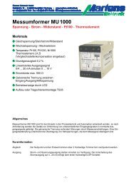
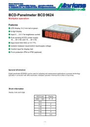
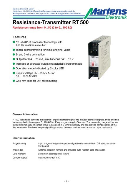
<strong>Resistance</strong>-<strong>Transmitter</strong> RT 500<br />
<strong>Resistance</strong> range from 0...50 Ω to 0...100 kΩ<br />
<strong>Elektronik</strong><br />
Features<br />
M 12 Bit AD/DA processor technology with<br />
250 Hz realtime execution<br />
M Teach-in programming for initial and final value<br />
M 2- and 3-wire connection<br />
M Output for 0/4 ... 20 mA, simultaneous 0/2 ... 10 V<br />
M Increase or decrease output characteristic programmable<br />
M Operation mode indicated by 2-color LED<br />
M Supply voltage 85 ... 265 V AC or<br />
10 ... 30 V AC/DC<br />
M 22.5 mm case for DIN rail mounting<br />
General information<br />
<strong>RT500</strong> transmitter converts a resistance- or potentiometer signal into industry standard signals. Initial and final<br />
value may be in the range of 0...100 kOhm. Easy programming by Teach-in. The measuring range will be selected<br />
automatically. The input circuit is designed in 3-wire technology and can provide compensation of the<br />
line resistance. The linear output-signal is generated between minimum and maximum input resistance.<br />
Short information<br />
Programming<br />
Watch-dog<br />
Data memory<br />
Current output<br />
input programming and output configuration is selected with DIP switches at the<br />
front panel<br />
watches program running and provides auto-reset in case of an error<br />
protection against power failure<br />
maximum burden 1 kΩ<br />
- 1 -
Technical data<br />
Power supply<br />
Supply voltage : 85 ... 265V AC or 10 ... 30V AC/DC<br />
Frequency AC : 47 ... 63 Hz<br />
Power consumption : < 3VA<br />
Operating temperature : -10 ... +50 °C<br />
Rated voltage : 500V• according to German VDE 0110 Group 3<br />
between input, output/power supply<br />
Test voltage<br />
: 4 kV= between power supply and input/output<br />
- conformity : EN55022, EN60555, IEC61000-4-4/5/11/13<br />
Input<br />
<strong>Resistance</strong> range<br />
Measuring voltage<br />
and - current<br />
Resolution<br />
Sampling frequency<br />
Cable resistance<br />
: Rmax: 50 Ω ... 100 kΩ, cond.: △R ≥ 0.5 Rmax (lower values on request)<br />
increasing or decreasing output characteristic programmable.<br />
Measuring<br />
voltage<br />
1 V<br />
2 V<br />
4 V<br />
6,25 mA<br />
100 Ω<br />
-<br />
-<br />
Measuring current<br />
2,5 mA 250 µA<br />
250 Ω 2,5 kΩ<br />
500 Ω 5 kΩ<br />
1 kΩ 10 kΩ<br />
25 µA<br />
25 kΩ<br />
50 kΩ<br />
100 kΩ<br />
: 600 ... 3000 digit (depends on measurement range)<br />
: 250 Hz real-time processing<br />
: 10 Ω max. Automatic compensation in 3-wire-circuits with<br />
symmetric line-resistance<br />
<strong>Resistance</strong> values<br />
for maximum<br />
resolution!<br />
Output<br />
Current output : 0/4 ... 20 mA switch selectable; load ≤ 1 kΩ<br />
Voltage output : 0/2 ... 10 V switch selectable; load 15 mA max., short-circuit-protection<br />
(simultaneous to current output 5 mA max.)<br />
Attention! No isolation between input and output!<br />
Rise time (t90) : < 8 ms<br />
Accuracy : < 0.2 %<br />
Temperature coefficient : ≤100 ppm/°C<br />
Case<br />
Weight<br />
Protection<br />
Connection<br />
: standard case of polycarbonate 8020 UL94V-1<br />
: approx. 200 g<br />
: Case IP30, terminals IP20 finger safe acc. to German BGV A3<br />
: screw-terminals with pressure plate max 2.5 mm², wire<br />
Programming<br />
Programming resistance measuring range<br />
1 Set resistance (Rmin) at terminals 1,2,3<br />
2 S1 ON -> <strong>RT500</strong> stores the value of Rmin<br />
3 -> LED flashes green = OK<br />
-> LED flashes red = error (see status LED)<br />
4 S1 OFF<br />
5<br />
6<br />
7<br />
8<br />
9<br />
Set resistance (Rmax) at Terminals 1,2,3<br />
S2 ON -> <strong>RT500</strong> stores the value of Rmax<br />
see point 3<br />
S2 OFF -> Programming of the measuring range is<br />
now completed<br />
Set with S3 the wanted output configuration<br />
Status of the front side LED<br />
OFF green Operation mode<br />
red Measuring range exeeded or break of line<br />
ON<br />
red/green<br />
flashing<br />
LED off<br />
(2 sec.)<br />
green<br />
flashing<br />
red<br />
flashing<br />
red<br />
Last programming invalid.<br />
<strong>Resistance</strong> value could not be stored<br />
<strong>Resistance</strong> value stored<br />
Measured resistance value has been stored in the<br />
EEPROM<br />
The difference of the resistance is smaller than<br />
20 ... 50% (depending on measuring range) of Rmax<br />
Measured value exceeds the max. value of 100 kΩ.<br />
<strong>Resistance</strong> value could not be stored.<br />
Examples:<br />
1.) Measuring range 15 ... 90 Ω<br />
2.) Measuring range 0 ... 1 kΩ<br />
3.) Measuring range 100 ... 200 Ω<br />
Attention! Minimal span 0.5 Rmax<br />
- 2 -
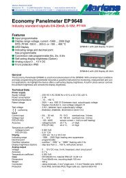
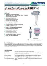
Connection diagram<br />
Front panel controls<br />
Attention!<br />
No connection between<br />
input and output!<br />
Shield not at PE!<br />
Status-LED<br />
50Ω ≤ ΔR ≤ 100kΩ<br />
Shield<br />
Outputs<br />
0/2 ... 10 V<br />
0/4 ... 20 mA<br />
Inputs<br />
Programming<br />
switch<br />
Potentiometer<br />
3-wireconnection<br />
2-wireconnection<br />
Outputconfiguration<br />
Supply voltage<br />
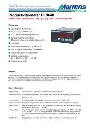
Dimensions<br />
Caution!<br />
Mounting of multiple units<br />
without distance is only<br />
permitted in horizontal<br />
orientation.<br />
TS35 DIN rail mounting<br />
acc. to DIN 46277 and DIN EN 50022<br />
- 3 -
<strong>Martens</strong> <strong>Elektronik</strong> <strong>GmbH</strong><br />
Kiebitzhörn 18 • D-22885 Barsbüttel/Germany • www.martens-elektronik.de<br />
F+49-(0)40-670 73-0 • Fax +49-(0)40-670 73-288 • J info@martens-elektronik.de<br />
<strong>Elektronik</strong><br />
Ordering code<br />
<strong>RT500</strong> -<br />
1.<br />
-<br />
2.<br />
1. Measuring range<br />
40 Rmax programmable from 50 Ω up to 100 kΩ<br />
(see examples page 2)<br />
2. Supply voltage<br />
0<br />
5<br />
85 ... 265 V AC<br />
10 ... 30 V AC/DC<br />
Note:<br />
Configuration is possible ex factory without extra charge.<br />
Please state the desired data, when ordering.<br />
E.g.: 0 ... 250 Ω or 150 ... 800 Ω<br />
10/03-00<br />
- 4 -