10. Seismic Stratigraphy
10. Seismic Stratigraphy
10. Seismic Stratigraphy

Create successful ePaper yourself
Turn your PDF publications into a flip-book with our unique Google optimized e-Paper software.
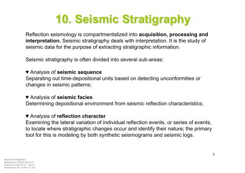
<strong>10.</strong> <strong>Seismic</strong> <strong>Stratigraphy</strong><br />
Reflection seismology is compartmentalized into acquisition, processing and<br />
interpretation. <strong>Seismic</strong> stratigraphy deals with interpretation. It is the study of<br />
seismic data for the purpose of extracting stratigraphic information.<br />
<strong>Seismic</strong> stratigraphy is often divided into several sub-areas:<br />
♥ Analysis of seismic sequence<br />
Separating out time-depositional units based on detecting unconformities or<br />
changes in seismic patterns;<br />
♥ Analysis of seismic facies<br />
Determining depositional environment from seismic reflection characteristics;<br />
♥ Analysis of reflection character<br />
Examining the lateral variation of individual reflection events, or series of events,<br />
to locate where stratigraphic changes occur and identify their nature; the primary<br />
tool for this is modeling by both synthetic seismograms and seismic logs.<br />
Sequence <strong>Stratigraphy</strong><br />
Department of Earth Sciences<br />
National Central Univ., Taiwan<br />
Prepared by Dr. Andrew T. Lin<br />
1
<strong>10.</strong>1 Nature of<br />
a reflection<br />
seismic<br />
section<br />
An example header<br />
A typical oil industry<br />
seismic section consists<br />
of<br />
(1) a header;<br />
(2) the main body of<br />
seismic data that consist<br />
of a series of seismic<br />
traces;<br />
(3) shot points or<br />
common depth points;<br />
(4) velocity analyses.<br />
Sequence <strong>Stratigraphy</strong><br />
Department of Earth Sciences<br />
National Central Univ., Taiwan<br />
Prepared by Dr. Andrew T. Lin<br />
Courtesy of Chinese Petroleum Corporation<br />
2
Main body of<br />
seismic data<br />
(courtesy of CPC)<br />
Display of <strong>Seismic</strong> Data<br />
A series of vertical wiggle traces:<br />
Most seismic reflection data<br />
consists of a series of closely<br />
spaced, vertical wiggle traces.<br />
These traces resemble a series of<br />
A CDP<br />
gather<br />
shots and receivers<br />
at the same<br />
location. So called<br />
vertical incidence<br />
arrangement. A<br />
single seismic trace<br />
is a stacked trace of<br />
a CDP gather as<br />
shown on the left.<br />
Sequence <strong>Stratigraphy</strong><br />
Department of Earth Sciences<br />
National Central Univ., Taiwan<br />
Prepared by Dr. Andrew T. Lin<br />
Two-way travel time<br />
(TWT): Have to reduce<br />
time by 1/2 before<br />
multiplying times velocity<br />
to convert to depth.<br />
3
The fold of stacking refers to the number of traces in the CDP gather and may<br />
conventionally be 6. 12, 24, 48..<br />
CDP spacing = 1 / 2<br />
x group (channel) interval<br />
maximum CDP fold =<br />
Velocity increases with<br />
depth: Time section is<br />
compressed in terms of depth<br />
at greater times. Hence depth<br />
converted profiles have better<br />
representations of geometry.<br />
number of channels x group interval<br />
2x shot interval<br />
Vertical Exaggeration: Usually<br />
significant, and variable in depth.<br />
Boggs (2001), p.498<br />
Sequence <strong>Stratigraphy</strong><br />
Department of Earth Sciences<br />
National Central Univ., Taiwan<br />
Prepared by Dr. Andrew T. Lin<br />
4
◎ Nature of a reflection<br />
Velocity-porosity relationship<br />
Time-average equation:<br />
1<br />
v<br />
=<br />
φ 1−φ<br />
+<br />
v f<br />
v m<br />
v: velocity in the saturated rock<br />
Φ: porosity<br />
v f : fluid velocity<br />
v m : velocity of the matrix<br />
Velocity-density relationship<br />
ρ = 0.23v<br />
0.25<br />
Gardner’s equation<br />
Sequence <strong>Stratigraphy</strong><br />
Department of Earth Sciences<br />
National Central Univ., Taiwan<br />
Prepared by Dr. Andrew T. Lin<br />
Doyle and Bennett (1998), p.279<br />
Impedance contrasts: Reflections<br />
caused by impedance contrasts.<br />
The impedance (Z) of a rock unit is<br />
the product of its velocity (v) and<br />
density (ρ), that is Z= vρ.<br />
At normal incidence, Reflection<br />
Coefficient:<br />
RC = (Z 2<br />
-Z 1<br />
)/(Z 1<br />
+Z 2<br />
)<br />
5
♥ Amplitude<br />
Reflection amplitude has to do with seismic wave height and is a function of the<br />
energy of seismic waves. On a seismic record, amplitude is measured as the<br />
distance from the mid-position of a wave to the extreme position. Amplitude is<br />
directly proportional to RC. It is also affected by the spacing between reflecting<br />
surfaces. Where bed spacing is optimum, lower energy responses are phased<br />
together constructively (constructive interference) to intensity or amplify the<br />
reflected energy and thus increase amplitude.<br />
Sequence <strong>Stratigraphy</strong><br />
Department of Earth Sciences<br />
National Central Univ., Taiwan<br />
Prepared by Dr. Andrew T. Lin<br />
Boggs (2001), p.497<br />
6
♥ Polarity<br />
Positive RC produces a positive reflection, by definition and negative RC produces<br />
a negative reflection. Determine polarity from known impedance boundary, for<br />
example the water bottom (positive).<br />
Sequence <strong>Stratigraphy</strong><br />
Department of Earth Sciences<br />
National Central Univ., Taiwan<br />
Prepared by Dr. Andrew T. Lin<br />
Where to Pick Actual onset of reflection<br />
corresponds to impedance contrast or<br />
geological boundary in Minimum Phase<br />
Data. Data can be processed to Zero<br />
Phase such that peak amplitude of a<br />
symmetrical wavelet lies over impedance<br />
contrast. In any case you pick on the<br />
peak because that is what is easy and in<br />
the case of minimum phase data, make<br />
any necessary adjustment for the<br />
distance between the reflector and the<br />
geologic boundary. Most, if not all,<br />
seismic sections are displayed in<br />
minimum phase data.<br />
(Definitions: Minimum phase: a<br />
characteristic of waveforms which have<br />
their energy concentrated early in the<br />
waveform; Zero phase: a characteristic<br />
waveforms which are symmetrical.)<br />
Badley (1985), p.9<br />
Minimumphase<br />
wavelet<br />
Zero-phase<br />
wavelet<br />
7
Frequency: The frequency spectrum of the<br />
acoustic signal generated varies according to<br />
the energy sources.<br />
Sequence <strong>Stratigraphy</strong><br />
Department of Earth Sciences<br />
National Central Univ., Taiwan<br />
Prepared by Dr. Andrew T. Lin<br />
Doyle and Bennett (1998), p.284<br />
8
<strong>10.</strong>2 Resolution of seismic data<br />
A. Vertical resolution<br />
This can be defined as the minimum vertical distance between two interfaces<br />
needed to give rise to a single reflection that can be observed on a seismic section.<br />
Resolution depends on wavelength of signal at depth in question, which depends<br />
on frequency and velocity.<br />
Wavelength (λ)= Velocity (v) x period (T)<br />
= Velocity (v) /Frequency (f).<br />
The average vertical<br />
resolution for oil company<br />
seismic reflection data is<br />
about 10 m at shallow<br />
depth and 100 m in deeper<br />
crust depending upon the<br />
wavelengths involved.<br />
Photo: Andrew Lin<br />
Sequence <strong>Stratigraphy</strong><br />
Department of Earth Sciences<br />
National Central Univ., Taiwan<br />
Prepared by Dr. Andrew T. Lin<br />
Emery & Myers (1996), p.46<br />
Big Ben in London<br />
9
◎ The higher the frequency of the waveform, the greater or better will be the<br />
vertical resolution.<br />
Doyle and Bennett (1998), p.285<br />
Badley (1985), p.26<br />
Because velocity increases with depth and frequency decreases with depth resolution<br />
goes down. Typically tops and bottoms of beds resolved by TWT of λ/2. Once the<br />
bed is about λ/30 thick or less, reflections from the top and base effectively cancel<br />
and there is no detectable seismic response.<br />
Sequence <strong>Stratigraphy</strong><br />
Department of Earth Sciences<br />
National Central Univ., Taiwan<br />
Prepared by Dr. Andrew T. Lin<br />
10
Thin-bed effect<br />
or tuning<br />
Reflectors that<br />
are spaced more<br />
closely than onequarter<br />
thick<br />
(λ/4 )of the<br />
wavelength have<br />
responses that<br />
begin to add<br />
constructively to<br />
produce a<br />
reflection with high amplitude.<br />
λ/30<br />
λ/4<br />
λ/2<br />
Emery & Myers (1996), p.47<br />
Sequence <strong>Stratigraphy</strong><br />
Department of Earth Sciences<br />
National Central Univ., Taiwan<br />
Prepared by Dr. Andrew T. Lin<br />
Badley (1985), p.18<br />
11
Interference: the superposition of<br />
waveforms. Many (perhaps most)<br />
reflections are the interference<br />
composites resulting from several<br />
interfaces. So there is no one-to-one<br />
correspondence between seismic<br />
events and interfaces in<br />
the Earth.<br />
Examples of interference on a<br />
zero-phase normal-polarity<br />
wavelet for a range of bed<br />
thickness and spacings.<br />
Sequence <strong>Stratigraphy</strong><br />
Department of Earth Sciences<br />
National Central Univ., Taiwan<br />
Prepared by Dr. Andrew T. Lin<br />
Badley (1985), p.16<br />
12
B. Lateral resolution<br />
The seismic energy travels as wave fronts and the region on the reflector where the<br />
seismic energy is reflected constructively is known as the Fresnel zone. Lateral<br />
resolution is determined by the radius of the Fresnel Zone, which itself depends on<br />
the wavelength of the acoustic pulse and the depth of the reflector. Fresnel zone<br />
are typically hundreds of meters.<br />
For example, for a plane that reflects<br />
interface at a depth of 1,000 m and an<br />
average velocity of 2,000 m/sec, the first<br />
Fresnel zone has a radius of 130 m for a<br />
60-Hz component and 183 m for a 30-Hz<br />
component. For a reflection at 4,000 m<br />
with an average velocity of 3,500 m/sec,<br />
the first Fresnel zone has a radius of 375<br />
m for a 50-Hz component and 594 m for a<br />
20-Hz component.<br />
Sequence <strong>Stratigraphy</strong><br />
Department of Earth Sciences<br />
National Central Univ., Taiwan<br />
Prepared by Dr. Andrew T. Lin<br />
Sheriff (1977) in AAPG Mem.26, p.11<br />
13
A “hole” within a bedding plane<br />
hole<br />
Sheriff (1977) in AAPG Mem.26, p.12<br />
Sequence <strong>Stratigraphy</strong><br />
Department of Earth Sciences<br />
National Central Univ., Taiwan<br />
Prepared by Dr. Andrew T. Lin<br />
Sheriff (1977) in AAPG Mem.26, p.13<br />
14
<strong>10.</strong>3 Chronostratigraphic significance of seismic reflections<br />
Primary seismic reflections follow chronostratigraphic (time-stratigraphic) correlation<br />
patterns rather than time-transgressive lithostratigraphic (rock-stratigraphic) units. In<br />
other words, seismic reflectors in many cases are time lines. They cut across major<br />
lithologic boundaries, especially those defined by outcrop sections or wells.<br />
(1) (2)<br />
Sequence <strong>Stratigraphy</strong><br />
Department of Earth Sciences<br />
National Central Univ., Taiwan<br />
Prepared by Dr. Andrew T. Lin<br />
Vail et al. (1977) in AAPG Mem.26, p.102<br />
Vail et al. (1977) in AAPG Mem.26, p.103<br />
15
Another example showing the<br />
chronostratigraphic significance<br />
of seismic reflections (Sherrif<br />
and Geldart, 1995, p. 403)<br />
(3)<br />
Vail et al. (1977)<br />
in AAPG Mem.26, p.105<br />
Sequence <strong>Stratigraphy</strong><br />
Department of Earth Sciences<br />
National Central Univ., Taiwan<br />
Prepared by Dr. Andrew T. Lin<br />
16
<strong>10.</strong>4 <strong>Seismic</strong> sequence analysis<br />
The procedures for interpreting stratigraphy from seismic data involve three principle<br />
stages: (1) seismic sequence analysis, (2) seismic facies analysis, and (3)<br />
interpretation of depositional environments and lithofacies (Vail, 1987).<br />
<strong>Seismic</strong> sequence (or a depositional sequence): A stratigraphic unit composed of<br />
a relatively conformable succession of genetically related strata and bounded at its<br />
top and base by unconformities or their correlative conformities.<br />
A depositional sequence has chronostratigraphic significance because all the rocks of<br />
the sequence were deposited during the interval of geological time defined by the<br />
ages of the sequence boundaries where they are conformities.<br />
Sequence <strong>Stratigraphy</strong><br />
Department of Earth Sciences<br />
National Central Univ., Taiwan<br />
Prepared by Dr. Andrew T. Lin<br />
next page<br />
17
Basic<br />
concept of a<br />
depositional<br />
sequence<br />
Mitchum et al. (1977) in AAPG Mem.26, p.54<br />
Sequence <strong>Stratigraphy</strong><br />
Department of Earth Sciences<br />
National Central Univ., Taiwan<br />
Prepared by Dr. Andrew T. Lin<br />
18
An idealized sequence<br />
Vail (1987)<br />
Sequence <strong>Stratigraphy</strong><br />
Department of Earth Sciences<br />
National Central Univ., Taiwan<br />
Prepared by Dr. Andrew T. Lin<br />
<strong>Seismic</strong> sequence analysis involves identification of major reflection<br />
“packages” that can be delineated by recognizing surfaces of<br />
discontinuity. Discontinuities may thus be recognized by interpreting<br />
systematic patterns of reflection terminations along the discontinuity<br />
surfaces.<br />
19
Emery & Myers (1996), p.53<br />
toplap<br />
Erosional truncation<br />
is the termination of<br />
strata against an<br />
overlying erosional<br />
surface.<br />
http://ic.ucsc.edu/~casey/<br />
eart168/Lec.SeisStrat.htm<br />
Sequence <strong>Stratigraphy</strong><br />
Department of Earth Sciences<br />
National Central Univ., Taiwan<br />
Prepared by Dr. Andrew T. Lin<br />
onlap<br />
20
Apparent truncation is the termination of relatively low-angle seismic reflections<br />
beneath a dipping seismic surface, where that surface represents marine<br />
condensation.<br />
Emery & Myers (1996), p.54<br />
Lapout is the lateral termination of a reflection (generally a bedding plane) at its<br />
depositional limit.<br />
Baselap is the lapout of reflections against an underlying seismic surface (which<br />
marks the base of the seismic package). Baselap can consist of onlap or downlap.<br />
Sequence <strong>Stratigraphy</strong><br />
Department of Earth Sciences<br />
National Central Univ., Taiwan<br />
Prepared by Dr. Andrew T. Lin<br />
21
Onlap is recognized on seismic data by the termination of low-angle reflections<br />
against a steeper seismic surface. Two types of onlap are recognized: marine onlap<br />
and coastal onlap.<br />
Downlap is baselap in which an initially inclined stratum terminates downdip against<br />
an initially horizontal or inclined surface. The surface of downlap represents a marine<br />
condensed unit in most cases.<br />
Santa Cruz<br />
terrace deposits<br />
downlapping<br />
onto<br />
unconformity.<br />
http://ic.ucsc.edu/~casey/eart168/Lec.SeisStrat.htm<br />
Sequence <strong>Stratigraphy</strong><br />
Department of Earth Sciences<br />
National Central Univ., Taiwan<br />
Prepared by Dr. Andrew T. Lin<br />
22
Toplap is the termination of inclined reflections (clinoforms) against an overlying<br />
lower angle surface, where this is believed to represent the proximal depositional<br />
limit.<br />
Other term:<br />
Offlap: A conformable sequence of inclined strata, deposited during a marine<br />
regression, in which each stratum is succeeded laterally by progressively younger<br />
units (a clinoform).<br />
Clinoforms<br />
merging into<br />
toplap. Peru, a<br />
temperate water<br />
carbonate of<br />
Miocene age.<br />
Sequence <strong>Stratigraphy</strong><br />
Department of Earth Sciences<br />
National Central Univ., Taiwan<br />
Prepared by Dr. Andrew T. Lin<br />
http://ic.ucsc.edu/~casey/eart168/Lec.SeisStrat.htm<br />
23
Examples of erosional truncation<br />
(Mitchum et al., 1977)<br />
Sequence <strong>Stratigraphy</strong><br />
Department of Earth Sciences<br />
National Central Univ., Taiwan<br />
Prepared by Dr. Andrew T. Lin<br />
24
Examples of onlap<br />
(one kind of baselap)<br />
(Mitchum et al., 1977)<br />
Sequence <strong>Stratigraphy</strong><br />
Department of Earth Sciences<br />
National Central Univ., Taiwan<br />
Prepared by Dr. Andrew T. Lin<br />
25
Examples of downlap<br />
(one kind of baselap)<br />
(Mitchum et al., 1977)<br />
Sequence <strong>Stratigraphy</strong><br />
Department of Earth Sciences<br />
National Central Univ., Taiwan<br />
Prepared by Dr. Andrew T. Lin<br />
26
Examples of toplap<br />
(Mitchum et al., 1977)<br />
Sequence <strong>Stratigraphy</strong><br />
Department of Earth Sciences<br />
National Central Univ., Taiwan<br />
Prepared by Dr. Andrew T. Lin<br />
27
Steps in the stratigraphic interpretation of a seismic section<br />
1. Determine the vertical and horizontal scale of the section.<br />
2. Migrated section or not, marine or land data<br />
3. Identify multiples (e.g., water-bottom multiples, peg-leg multiples etc.) and mark them in light<br />
blue by convention.<br />
4. Identify and mark reflection terminations or unconformities (e.g. onlap, downlap, truncation<br />
etc.) with arrowheads (by convention use a red pencil).<br />
5. Identify seismic surfaces on the basis of reflection terminations (A seismic surface is a line<br />
on a seismic section where reflections terminate in a consistent manner.). In initial stages,<br />
mark seismic surfaces in yellow colour by convention. Then assign specific colour to<br />
individual seismic surface based on its type (e.g. sequence boundary, transgressive surface,<br />
maximum flooding surface etc.) or age in later stages of stratigraphic interpretation.<br />
6. Identify sequence boundaries. Sequence boundaries are commonly marked by truncation or<br />
onlap, whereas maximum-flooding surfaces are commonly marked by downlap.<br />
7. Carry out a similar exercise on other intersected seismic lines and tie the seismic surfaces<br />
and interpretation (i.e., ensure that the interpretation is consistent where lines cross) around<br />
the data set.<br />
8. Mapping sequence units on the basis of thickness, geometry, orientation, or other features<br />
to see how each sequence relates to neighboring sequences.<br />
9. Identify seismic facies for each sequence.<br />
<strong>10.</strong> Interpretation of depositional environments and lithofacies.<br />
Sequence <strong>Stratigraphy</strong><br />
Department of Earth Sciences<br />
National Central Univ., Taiwan<br />
Prepared by Dr. Andrew T. Lin<br />
28
Practical:<br />
On the following figure, overlay a piece of tracing paper and do the following:<br />
1. Pick reflection terminations;<br />
2. Draw lines of seismic surfaces.<br />
The seismic data is from the Outer Moray Firth, central North Sea, showing the<br />
seismic stratigraphy of the post-Palaeocene section. The surface at around 0.7<br />
second is dated as close to the top of the Miocene, and the high-relief surfaces in<br />
the shallower section are interpreted as glacial lowstand surfaces in the Pliocene-<br />
Pleistocene.<br />
Sequence <strong>Stratigraphy</strong><br />
Department of Earth Sciences<br />
National Central Univ., Taiwan<br />
Prepared by Dr. Andrew T. Lin<br />
29
Sequence <strong>Stratigraphy</strong><br />
Department of Earth Sciences<br />
National Central Univ., Taiwan<br />
Prepared by Dr. Andrew T. Lin<br />
sec<br />
30
<strong>10.</strong>5 <strong>Seismic</strong> facies analysis<br />
<strong>Seismic</strong> facies analysis takes the interpretation process one step beyond seismic<br />
sequence analysis by examining within sequences smaller reflection units that may<br />
be the seismic response to lithofacies.<br />
<strong>Seismic</strong> facies are packages of reflectors with a set of seismic characteristics<br />
differing from adjacent units (similar to definition of a “formation”-must be<br />
distinguishable from adjacent units and mappable on earth's surface).<br />
Keystones in seismic facies analysis (Sangree and Widmier, 1979):<br />
1. An understanding of the effects of lithology and bed spacing on reflection parameters:<br />
amplitude, frequency, continuity of reflections.<br />
Sequence <strong>Stratigraphy</strong><br />
Department of Earth Sciences<br />
National Central Univ., Taiwan<br />
Prepared by Dr. Andrew T. Lin<br />
Feature of<br />
Reflectors<br />
Amplitude<br />
Frequency<br />
Continuity<br />
Geological Interpretation (Sangree Widmier, 1979)<br />
Impedance (velocity-density) contrasts, Layer spacing<br />
(cause constructive and destructive interference),<br />
Fluid content<br />
Bed spacing, Fluid content<br />
Beddding or layer continuity, depositional processes<br />
31
Presence of gas may cause “bright spots” effect.<br />
Sequence <strong>Stratigraphy</strong><br />
Department of Earth Sciences<br />
National Central Univ., Taiwan<br />
Prepared by Dr. Andrew T. Lin<br />
<strong>Seismic</strong><br />
response for a<br />
sand with a<br />
gradational<br />
base, which<br />
results in lower<br />
amplitude. The<br />
9-m thickness<br />
is about 1/8<br />
wavelength.<br />
32
2. Parallelism of reflection cycles to gross bedding, and therefore, to physical surfaces<br />
that separate older from younger sediments :<br />
Reflection configurations.<br />
Reflection configuration refers to the gross stratification patterns identified on<br />
seismic records.<br />
Feature of<br />
Reflectors<br />
Reflection<br />
Configuration<br />
(pattern)<br />
External form<br />
and areal<br />
association of<br />
seismic facies<br />
units<br />
Geological Interpretation (Sangree Widmier, 1979)<br />
Stratification patterns, Depositional processes, Erosion<br />
and paleotopography<br />
Gross depositional environment, Sediment source,<br />
Geologic setting<br />
Sequence <strong>Stratigraphy</strong><br />
Department of Earth Sciences<br />
National Central Univ., Taiwan<br />
Prepared by Dr. Andrew T. Lin<br />
33
Principle reflection patterns<br />
1. Parallel and subparallel: generated by strata that were probably deposited at<br />
uniform rates on a uniformly subsiding shelf or in a stable basin setting.<br />
Sequence <strong>Stratigraphy</strong><br />
Department of Earth Sciences<br />
National Central Univ., Taiwan<br />
Prepared by Dr. Andrew T. Lin<br />
34
2. Divergent: Divergent<br />
configurations are<br />
characterized by a<br />
wedge-shaped unit in<br />
which lateral thickening<br />
of the entire unit is<br />
caused by thickening of<br />
individual reflection<br />
subunits within the main<br />
unit. Divergent<br />
configurations are<br />
interpreted to signify<br />
lateral variations in rates<br />
of deposition or<br />
progressive tilting of the<br />
sedimentary surface<br />
during deposition.<br />
Sequence <strong>Stratigraphy</strong><br />
Department of Earth Sciences<br />
National Central Univ., Taiwan<br />
Prepared by Dr. Andrew T. Lin<br />
35
3. Prograding: Generated by strata that were deposited by lateral outbuilding or<br />
progradation to form gently sloping depositional surfaces called clinoforms.<br />
Prograding reflection configurations may include patterns of sigmoid (superposed S-<br />
shaped reflectors) and oblique, complex sigmoid-oblique, shingled, hummocky.<br />
Sequence <strong>Stratigraphy</strong><br />
Department of Earth Sciences<br />
National Central Univ., Taiwan<br />
Prepared by Dr. Andrew T. Lin<br />
Mitchum et al. (1977), p.125<br />
36
Examples of<br />
prograding<br />
configuration<br />
pattern<br />
Sigmoid<br />
Tangential oblique<br />
Parallel oblique<br />
Complex<br />
sigmoid-oblique<br />
Mitchum et al. (1977), p.126<br />
Sequence <strong>Stratigraphy</strong><br />
Department of Earth Sciences<br />
National Central Univ., Taiwan<br />
Prepared by Dr. Andrew T. Lin<br />
37
Examples of prograding<br />
configuration pattern<br />
Mitchum et al. (1977), p.127<br />
Sequence <strong>Stratigraphy</strong><br />
Department of Earth Sciences<br />
National Central Univ., Taiwan<br />
Prepared by Dr. Andrew T. Lin<br />
38
4. Chaotic: This<br />
pattern is<br />
interpreted to<br />
represent a<br />
disordered<br />
arrangement of<br />
reflection surfaces<br />
owing to<br />
penecontemporan<br />
eous, softsediment<br />
deformation, or<br />
possibly to<br />
deposition of<br />
strata in a variable,<br />
high-energy<br />
environment.<br />
Mitchum et al. (1977), p.129<br />
Sequence <strong>Stratigraphy</strong><br />
Department of Earth Sciences<br />
National Central Univ., Taiwan<br />
Prepared by Dr. Andrew T. Lin<br />
39
5. Reflection-free: This<br />
pattern may represent<br />
homogeneous, nonstratified<br />
units such as<br />
igneous masses or<br />
thick salt deposits, or<br />
highly contorted or very<br />
steeply dipping strata.<br />
Modifying terms<br />
Sequence <strong>Stratigraphy</strong><br />
Department of Earth Sciences<br />
National Central Univ., Taiwan<br />
Prepared by Dr. Andrew T. Lin<br />
Mitchum et al. (1977), p.130<br />
40
External forms of seismic facies units<br />
Sediment waves<br />
Sequence <strong>Stratigraphy</strong><br />
Department of Earth Sciences<br />
National Central Univ., Taiwan<br />
Prepared by Dr. Andrew T. Lin<br />
Mitchum et al. (1977), p.133<br />
41
A summary for geological interpretation of seismic facies parameters<br />
Sequence <strong>Stratigraphy</strong><br />
Department of Earth Sciences<br />
National Central Univ., Taiwan<br />
Prepared by Dr. Andrew T. Lin<br />
Mitchum et al. (1977), p.118<br />
42
Interpretation of lithofacies and depositional environments<br />
Once the objective aspects of delineating seismic sequences and facies have been<br />
completed, the final objective is to interpret the facies in terms of lithofacies,<br />
depositional environments, and paleobathymetry.<br />
The most useful seismic parameters in seismic faces analysis are the following:<br />
1. The geometry of reflections (reflection amplitude, continuity, frequency) and<br />
reflection terminations (onlap, downlap, erosional truncation, toplap…).<br />
1. Reflection configuration (parallel, divergent, sigmoid, or oblique)<br />
2. Three dimensional form.<br />
Boggs (2001), p.507<br />
Sequence <strong>Stratigraphy</strong><br />
Department of Earth Sciences<br />
National Central Univ., Taiwan<br />
Prepared by Dr. Andrew T. Lin<br />
43
<strong>Seismic</strong> facies classification<br />
“A,B,C technique” for two-dimensional seismic facies analysis (Ramasayer, 1979)<br />
These codes can be marked on a map:<br />
Emery & Myers (1996), p.58<br />
Emery & Myers (1996), p.56<br />
There is no unequivocal link between seismic<br />
facies and depositional systems, with the probable<br />
exception of the link between clinoforms and slope<br />
systems. Continuous flat-lying reflections may, for<br />
example, reflect deep-marine shales, coastal-plain<br />
topsets, alluvial plain, or lacustrine facies.<br />
Sequence <strong>Stratigraphy</strong><br />
Department of Earth Sciences<br />
National Central Univ., Taiwan<br />
Prepared by Dr. Andrew T. Lin<br />
C-Dwn/Ob<br />
44
Summary of seismic facies<br />
characterized by parallel and<br />
divergent reflection<br />
configurations<br />
From Badley (1985) adapted<br />
from Vail et al. (1977).<br />
Sequence <strong>Stratigraphy</strong><br />
Department of Earth Sciences<br />
National Central Univ., Taiwan<br />
Prepared by Dr. Andrew T. Lin<br />
45
Summary of seismic facies<br />
characterized by<br />
progradational reflection<br />
configurations<br />
From Badley (1985) adapted<br />
from Vail et al. (1977).<br />
Sequence <strong>Stratigraphy</strong><br />
Department of Earth Sciences<br />
National Central Univ., Taiwan<br />
Prepared by Dr. Andrew T. Lin<br />
46
Summary of seismic facies<br />
characterized by mounded<br />
and draped reflection<br />
configurations<br />
From Badley (1985) adapted<br />
from Vail et al. (1977).<br />
Sequence <strong>Stratigraphy</strong><br />
Department of Earth Sciences<br />
National Central Univ., Taiwan<br />
Prepared by Dr. Andrew T. Lin<br />
47
Summary of seismic facies<br />
characterized by onlap and fill<br />
reflection configurations<br />
From Badley (1985) adapted<br />
from Vail et al. (1977).<br />
Sequence <strong>Stratigraphy</strong><br />
Department of Earth Sciences<br />
National Central Univ., Taiwan<br />
Prepared by Dr. Andrew T. Lin<br />
48