SCAN DRIVE SYSTEM SD 2000 - Terco
SCAN DRIVE SYSTEM SD 2000 - Terco
SCAN DRIVE SYSTEM SD 2000 - Terco

Create successful ePaper yourself
Turn your PDF publications into a flip-book with our unique Google optimized e-Paper software.
<strong>SCAN</strong> <strong>DRIVE</strong> <strong>SYSTEM</strong><br />
<strong>SD</strong> <strong>2000</strong>
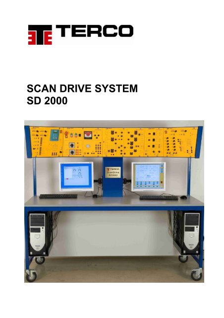
Scan Drive System - Mobile Motor Drive Teaching Unit<br />
<strong>SD</strong> <strong>2000</strong><br />
A complete mobile system for teaching electrical machines and drives. The system<br />
covers everything from basic electrical machines to computerized 4-quadrant drive of<br />
induction motor.<br />
The TERCO Scan Drive System is a learning system including both hardware and<br />
courseware, integrated to cover complete education in electrical machines and motor<br />
drives,<br />
thus opening a new path where teaching could reach the necessary goals to move<br />
industry ahead.<br />
The Scan Drive System is designed and adapted for compatibility and flexibility in<br />
pedagogical work for technical and vocational education as well as for engineering<br />
courses.<br />
It is designed for active participation by the student who can work independently,<br />
which creates a high degree of student motivation.<br />
Courses, that by tradition are treated separately, like electrical machines and power<br />
electronics, can with advantage be taught in an integrated way using the Scan Drive<br />
System.<br />
-2-
Scan Drive System<br />
<strong>SD</strong> <strong>2000</strong><br />
Highlights of <strong>Terco</strong> Scan Drive Systems<br />
• Four quadrant industrial drive Systems AC + DC<br />
• Covers most common electrical machines, static and rotary<br />
• Microprocessor based measuring system. Can display 26 different signals<br />
simultaneously<br />
• Vector visualization of electrical parameters<br />
• Digital Torque and Power meter<br />
• Equipped with double PC:s including 19” flat screens<br />
• Unique connection / experiment board, protected by microprocessor controlled<br />
blocking unit<br />
• Mobile main frame fabricated in steel and finished in baked blue enamel<br />
• Separate mobile machine bed with high torsional strength<br />
• Student surface 830 x <strong>2000</strong> mm<br />
• Full protection against over temp and over current<br />
• Outlets for oscilloscope measurements<br />
• 1-2-3-6 pulse rectifier<br />
• Separate torque meter to measure start torque<br />
• Machine set including 4 special made test machines allowing 20% overload<br />
during min 10 min.<br />
• Single and 3-phase variable transformer<br />
• 3-phase capacitive, inductive and resistive variable load banks<br />
• Build in UIP-unit to visualize, by multiplexer, immediate values of voltage,<br />
current and power simultaneously on a two channel oscilloscope explaining<br />
the 4Q operation in a unique way.<br />
• Complete power supply<br />
• Teachers manual, students experiment manual and technical description with<br />
diagrams.<br />
-3-
AC and DC Drives<br />
Engineers and technicians concerned with modern drive technology are today confronted with a whole<br />
complex of subjects like mechanics, electro mechanics, power conversion, electrical machines, power<br />
electronics, electronics, microcomputers, control theory, sensors and transducers, etc.<br />
With the Scan Drive System essential elements of these subjects can be integrated in a single course<br />
in electronic motion control. By use of new methodology of learning, integrated with the TERCO Scan<br />
Drive System, the course work, will be much easier for the teacher and more efficient for the student.<br />
4 Q frequency converter with MOS FET technique and a fixed intermediate DC-link<br />
Industrial converter, covers latest development in AC motor operation with frequency<br />
converters. The converter is designed to work according to different function principles and it<br />
is possible to explain several different types of frequency converters existing today.<br />
The converter is also suitable for experiments and tests in industries far beyond the area that<br />
the experiments show. When braking, the energy is transferred by the DC-link and a brake<br />
chopper to a built in load resistor. There is also an additional adjustable DC-injection brake.<br />
Operation can be done in three ways: manually, by alpha numeric display or from the built in<br />
PC.<br />
Built in Instruments and Oscilloscope functions.<br />
The enclosed software will make it possible to configure the internal connections and<br />
operating principles through the build in computer. On the screen it is possible to monitor 3<br />
analogue instruments and scroll a number of signals /parameters in parallel, which can be<br />
saved and printed. The number of parameters/tags possible to study exceeds 200.<br />
Standard Settings and Advanced Settings.<br />
Most parameters are set by default but settings can also be done manually from the front<br />
controls. Typically: Speed, Max Seed, Acc ramp, Flux Ret ramp, Lim, etc.<br />
-4-
4-Q DC motor Drive Module<br />
This Rectifier covers the latest development in DC motor operation with analogue<br />
control.<br />
The equipment is designed to work according to different industrial environments.<br />
The drive has signal in-and outputs for connections to slave and/or master drives.<br />
The design will enhance the possibilities of learning the theory and practice of<br />
understanding the operation of 4Q-drives for both single drives and the basic<br />
understanding of three bridges and their commutation.<br />
The 4Q-DC Drive can be used in the conception of speed/torque control versus<br />
electro machine theory.<br />
When braking the energy is transferred directly to the supplying network by operating<br />
in all four quadrants.<br />
Standard Settings<br />
12 Parameters are set manually.<br />
Typically: Speed, Max Speed, Acc ramp, Flux, Ret ramp, Lim, Current/Speed<br />
proportional, Current demand in/out, etc.<br />
Floating switches and potentiometers are used to study step response and stability.<br />
The results of the dynamic response regarding voltage, current and immediate power<br />
can be studied fully isolated on a standard oscilloscope via the built in isolation<br />
amplifier and multiplexer.<br />
-5-
Connection Module<br />
Scan Drive connection board includes preset exercises on screen<br />
and automatic blocking system.<br />
• The unique connection board of the control unit will make it possible to<br />
connect most experiment configurations in less than a minute.<br />
• The connection board switches are controlled by a microprocessor controlled<br />
blocking unit, to prevent faulty connections between power supplies and<br />
drives.<br />
• The connection board is monitored on one of the fixed PC screens and<br />
indicating which switches are to be operated. The current path is indicated in<br />
red.<br />
• After finishing an experiment the connection board is reset by a push button.<br />
At resetting all used switches will lit up indicting how to restart.<br />
• The main 3-phase variac will automatically ( by servo) reset to 0-voltage after<br />
finishing an experiment.<br />
• Automatic blocking of DC-circuits when operating AC-and DC-drives or PWMfield<br />
circuits, to avoid over voltage and destroying of equipment<br />
-6-
Measuring system<br />
The <strong>SCAN</strong> <strong>DRIVE</strong> measuring system is developed to cover all needs for<br />
measurement and studies of electrical machine drives, electric power and power<br />
electronics. It is designed with education in mind.<br />
The measuring system can show 26 different values simultaneously<br />
The picture also shows the connection board and current paths.<br />
It also shows how to integrate excel sheet for easy calculations.<br />
-7-
Power Module<br />
Power module including starting<br />
resistors for DC and Slip ring<br />
machines. Synchronizing unit,<br />
1-2-3-6 pulse bridge diode block,’<br />
1-phase transformer and 3-phase<br />
power supply<br />
‘<br />
Load module<br />
Load module including:<br />
3-phase DC resistive Load 0-1.5 kW in 13 steps<br />
3-phase Capacitive Load 0-1.5 KVAr ind in 13 steps<br />
3-phase Inductive Load 0-1.5 kVAr cap in 13 steps.<br />
Also including torque meter set and 2 - outgoing<br />
signals for oscilloscope.<br />
-8-
The pictures below shows the inside of <strong>SD</strong> <strong>2000</strong>, which is stacked with a lot of<br />
electronics and electrical components to provide for electrical and electronic signals<br />
required, as well as for maximum safety and control. The total weight of <strong>SD</strong> <strong>2000</strong> is<br />
more than 300 kgs.<br />
-9-
Scan Drive Machine Set with Torque and Power Meter.<br />
Machine Set with especially made test machines allowing overload of 20 % during<br />
min. 10 minutes without damaging the machines.<br />
One DC-Machine:<br />
Generator : 1.2 kW 1400 rpm<br />
Shunt motor : 1.0 kW 1400 rpm<br />
Series motor : 1.0 kW 1150 rpm<br />
Rotor : 220 V 5.5 A<br />
Excitation : 220 V 0.55 A<br />
Shaft height : 162 mm<br />
Weight : 45 kgs<br />
Open shunt and series winding for connections of separate-, shunt-, series and<br />
compound excitation.<br />
The series winding has an extra terminal at 2/3 of the winding. The DC-machine is<br />
equipped with commutating poles.<br />
-10-
One 4-pole Synchronous Machine with DC magnetized cylindrical rotor, including a<br />
damping winding that will counteract and also facilitate return to synchronism if the<br />
rotor falls out of phase.<br />
Synch. Gen. : 1.2 kVA x 0.8<br />
Synch. Motor : 1.0 kW<br />
Star conn. : 220 - 240 V, 3.5 A<br />
Delta conn. : 127 - 140 V, 6.1 A<br />
Weight : 39 kg<br />
One 1.1 kW Squirrel Cage Induction Motor<br />
4-pole machine : 1.1 kW 1400 rpm<br />
Start (Y) : 380 - 415, 3.0 A<br />
Delta (D) : 220 - 240 V, 5.2 A<br />
Weight : 19 kg<br />
One 1.1 kW Slip Ring Induction Motor<br />
4-pole : 1:1 kW 1400 rpm<br />
Star conn. : 380 -415 V, 3.2 A<br />
Delta conn. : 220 - 240 V, 5.5 A<br />
Weight : 42 kg<br />
One Digital Torque and Power Meter is fixed on the bed enabling torque<br />
measurements down to 120 rpm and speed measurement between 120 rpm and<br />
4000 rpm.<br />
Nominal torque 0-12 Nm<br />
Max. calibrated reading torque 15.0 Nm<br />
Max. mechanical load torque 25 Nm<br />
One separate torque meter for measuring of start torque.<br />
-11-
EXAMPLES OF EXPERIMENT<br />
1. To determine torque, speed<br />
and efficiency-curves for a<br />
separately excited DC-motor at<br />
rotor voltage control and also<br />
at field voltage control.<br />
2. To determine characteristic curves<br />
for a separately excited DC-<br />
Generator.<br />
3. To carry out basic standard<br />
measurements on the synchronous<br />
machine for the purpose of gaining<br />
insight into the construction,<br />
function and operation features of<br />
the machine.<br />
4. To investigate the operational<br />
features of the synchronous<br />
generator by performing a load test.<br />
5. To determine some of the<br />
characteristic graphs for a free<br />
running synchronous generator<br />
and determine the<br />
synchronous reactance of the<br />
machine.<br />
6. To verify the theoretical<br />
relationships for the various<br />
connections between diode<br />
configurations and rectifiers.<br />
7. Structure of a static converter for<br />
regulating rotation speed.<br />
8. Function controls of a frequency<br />
converter.<br />
9. Introduction of the UIP unit.<br />
10. Measurements with the UIP unit on<br />
the bus system with a sine-shape<br />
voltage with static loads<br />
11. Measurements with the UIP unit on<br />
a three-phase network with a nonesine-shape<br />
voltage.<br />
12. Measurements with the UIP unit on<br />
the network from the frequency<br />
converter.<br />
13. To study the function of a static<br />
frequency converter during<br />
induction motor operation.<br />
14. To study the frequency converter<br />
controlled manually during<br />
induction motor operation.<br />
15. To study the frequency converter<br />
controlled from Operator Station<br />
during induction motor operation.<br />
16. To study the frequency converter<br />
controlled from the built-in PC<br />
during induction motor operation.<br />
17. To study the function of the system<br />
during motor- and generator<br />
operation and at the same time<br />
determine operational / technical<br />
relations that are important for drive<br />
systems.<br />
18. To demonstrate the four quadrant<br />
operation of different electric<br />
machines.<br />
19. To investigate the operational<br />
features of the synchronous<br />
machine after synchronizing, both<br />
as a generator and as a motor<br />
during operation against a strong<br />
bus system.<br />
20. To investigate the operational<br />
features of a synchronous<br />
motor fed from a static<br />
frequency converter.<br />
21. To investigate the operational<br />
features in a synchronous machine<br />
network connected to a frequency<br />
converter, and to understand which<br />
control requirements the converter<br />
should fulfill during practical<br />
application.<br />
-12-
_________________________________________________________________<br />
www. terco.se