HW8 solutions - Itai Cohen Group
HW8 solutions - Itai Cohen Group
HW8 solutions - Itai Cohen Group
Create successful ePaper yourself
Turn your PDF publications into a flip-book with our unique Google optimized e-Paper software.
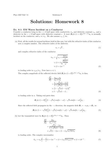
Phys 3327 Fall ’11 Solutions 8<br />
Solutions: Homework 8<br />
Ex. 8.1: EM Waves Incident on a Conductor<br />
Consider a conductor lying in the z > 0 half space with conductivity σ m and dielectric constant ǫ m , and a<br />
dielectric in the z > 0 half space with dielectric constant ǫ. A wave E 0 (r,t) = E 0 0e i(kz−ωt) e x is normally<br />
incident on the conductor, and ω ≪ σ m . We also assume ǫ m 4π.<br />
(a) First, allthe resultsfornormalincidenceholdinthiscase, butwiththe refractiveindexoftheconductor<br />
now a complex number. The refractive index of the dielectric<br />
and complex refractive index of the conductor<br />
√<br />
to leading order in ǫ m ω/σ m . Note here α ≪ 1.<br />
n 1 = √ ǫ , (1)<br />
n m = ǫ m +i 4πσ m<br />
ω<br />
√<br />
2πσm<br />
≃ (1+i)<br />
ω<br />
≡ (1+i)α −1 (2)<br />
The complex magnitude of the reflected electric field E 1 (r,t) = E 0 1 ei(kz−ωt) e x is then<br />
E 0 1<br />
E 0 0<br />
= n m −n 1<br />
n m +n 1<br />
= 1−√ ǫα(1−i)/2<br />
1+ √ ǫα(1−i)/2<br />
≃ [ 1− √ ǫα(1−i)/2 ] 2<br />
≃ 1− √ ǫα(1−i) , (3)<br />
to leading order in α. Taking real parts then<br />
[ (1−<br />
E 1 (r,t) = E0<br />
0 √ ) √ ]<br />
ǫα cos[kz −ωt]− ǫαsin[kz −ωt] e x . (4)<br />
Since the reflected field propagates in the −z direction, the magnetic field B 1 = −n 1 e z ×E 1 , so<br />
B 1 (r,t) = − √ [ (1−<br />
ǫE0<br />
0 √ ) √ ]<br />
ǫα cos[kz −ωt]− ǫαsin[kz −ωt] e y . (5)<br />
(b) Let the transmitted wave be E 2 (r,t) = E 0 2 ei(kmz−ωt) e x . Then<br />
E 0 2<br />
E 0 0<br />
to leading order. The complex wavenumber<br />
= 2n 1<br />
n m +n 1<br />
√ ǫ(1−i)α<br />
=<br />
1+ √ ǫα(1−i)/2<br />
≃ √ ǫ(1−i)α = (1−i) √ ǫω/2πσ m (6)<br />
k m = n m<br />
ω<br />
c = ω c (1+i)α−1 = (1+i) √ 2πσ m ω/c 2 ≡ (1+i)δ −1 . (7)<br />
1
Phys 3327 Fall ’11 Solutions 8<br />
(c) The magnetic field of the transmitted wave B 2 = n m e z ×E 2 . Hence<br />
in terms of only E 0 2 and k m.<br />
B 2 (r,t) = k mc<br />
ω E0 2e i(kmz−ωt) e y , (8)<br />
(d) Applying Ohm’s Law, the current density in the conductor j = σ m E 2 . Hence,<br />
j = σ m E 0 2e i(kmz−ωt) e x . (9)<br />
After taking real parts we have<br />
j(r,t) = σ m E0√ 0 ǫω/2πσm e −z/δ[ ]<br />
cos(δ −1 z −ωt)+sin(δ −1 z −ωt) . (10)<br />
(e) The time-averaged Poynting vector<br />
〈S〉 = c<br />
8π E 2 ×B ∗ 2<br />
= c<br />
8π e−2z/δ |E 0 2 |2 n ∗ m e z<br />
= ǫ<br />
8π 2 c 2<br />
δσ m<br />
(E 0 0 )2 e −2z/δ e z<br />
(11)<br />
after taking the real part only. Since there are free currents flowing in the conductor, then applying<br />
Ohm’s Law j = σ m E, the energy conservation law is<br />
∂<br />
∂t E +∇·S +σ mE 2 = 0 . (12)<br />
Ex. 8.2: Parallel Conducting Planes<br />
Consider two conducting planes, located at x = 0 and x = d, so their common surface normal is e x . The<br />
boundary condition for the two planes is<br />
e x ×E = 0 , and e x ·B = 0 . (13)<br />
Clearly, a TEM mode with k = ke z , E = Ee x and B = Be y satisfies the boundary conditions, so these<br />
plane support TEM modes.<br />
The proof that uniform cross-section hollow conductors do not support TEM modes depends on the conductor’s<br />
surface being closed (i.e. having no boundary) and connected. However, in the case of the two planes,<br />
the conducting surface is clearly not connected, so we do not expect TEM modes to be forbidden.<br />
Ex. 8.3: E & M Fields for a Transmission Line<br />
(a) Consider a coaxial cable with inner radius a and outer radius b, with the inner conductor at a potential<br />
V 0 with respect to the outer one. As found in previous homework, in the cylindrical coordinates (r,θ,z)<br />
the potential for a ≤ r ≤ b is<br />
and hence the electric field<br />
Φ(r) = −V 0<br />
ln(r/a)<br />
ln(b/a) , (14)<br />
E(r) = −∇Φ(r) = V 0 e r<br />
ln(b/a) r . (15)<br />
2
Phys 3327 Fall ’11 Solutions 8<br />
(b) Assuming the the current I 0 flows along the inner conductor in the +z direction, then by Ampère’s<br />
Law in integral form, clearly the magnetic field for a ≤ r ≤ b is<br />
B(r) = 2I 0<br />
c<br />
e θ<br />
r . (16)<br />
(c) Let V(z,t) = V 0 e i(kz−ωt) and I(z,t) = I 0 e i(kz−ωt) , and Z 0 = V 0 /I 0 . Consider the dynamical fields<br />
E(r,t) = V(z,t) e r<br />
ln(b/a) r = V 0<br />
ln(b/a)<br />
B(r,t) = 2I(z,t) e θ<br />
c r = 2I 0<br />
c<br />
e i(kz−ωt)<br />
r<br />
e i(kz−ωt)<br />
r<br />
e r (17)<br />
e θ . (18)<br />
which are obtained by näively replacing V 0 → V(z,t) and I 0 → I(z,t). Note these fields have not been<br />
derived from Maxwell’s equations, so the idea is to check that they satisfy the usual wave equations,<br />
and hence are the correct fields generated by V(z,t) and I(z,t).<br />
In the cylindrical coordinates chosen, we may write the electric field E = E r (r,z)e r . Using the hint<br />
provided, the Laplacian<br />
∇ 2 E = ∇ ( ∇·E ) −∇× ( ∇×E )<br />
) ∂<br />
= 0−∇×(<br />
∂z E r(r,z) e θ<br />
(<br />
= ik ∂ [<br />
rEr (r,z) ]) e r<br />
∂z r<br />
noting that ∂/∂r(rE r ) = 0. Hence<br />
∇ 2 E − 1 c 2 ∂ 2<br />
= −k 2 E , (19)<br />
∂t 2E = −k2 E + ω2<br />
c 2 E = 0 , (20)<br />
provided k = ω/c, and so the electric field (17) satisfies the wave equation.<br />
Similarly writing the magnetic field as B = B θ (r,z)e θ , then<br />
noting that ∂/∂r(rB θ ) = 0. Hence<br />
∇ 2 B = ∇ ( ∇·B ) −∇× ( ∇×B )<br />
) ∂<br />
= 0+∇×(<br />
∂z B θ(r,z) e r<br />
(<br />
= ik ∂ )<br />
∂z B θ(r,z)<br />
∇ 2 B − 1 c 2 ∂ 2<br />
e θ<br />
= −k 2 B , (21)<br />
∂t 2B = −k2 B + ω2<br />
c 2 B = 0 , (22)<br />
provided k = ω/c, and so the magnetic field (18) satisfies the wave equation.<br />
(d) The time-averaged Poynting vector<br />
〈S〉 = c<br />
8π E ×B∗<br />
= 1<br />
4π<br />
V 0 I 0<br />
ln(b/a)<br />
e z<br />
r 2 . (23)<br />
3
Phys 3327 Fall ’11 Solutions 8<br />
Hence the power transmitted through the interior cross section of the cable by the EM field is<br />
∫<br />
P = S ·dA<br />
= 1 V 0 I 0<br />
4π ln(b/a)<br />
= V 0I 0<br />
2<br />
∫ 2π ∫ b<br />
0<br />
a<br />
dr<br />
r<br />
. (24)<br />
Since the electric and magnetic fields outside the cable are zero, then P is the total power transmitted<br />
down the line by the EM wave. Note that P is the same as the rms power dissipated by the impedance<br />
Z 0 , which is I 2 0 Z 0/2.<br />
Ex. 8.4: Discrete Element Representation of a Transmission Line<br />
(a) Let the nth inductor be L n . The current running through L n is I n , and the impedance Z L = −iωL,<br />
assuming the ladder is driven by an external sinusoidal voltage or current source ∼ e −iωt . Note that<br />
the − sign in the exponential means that Z L is the opposite sign to the convention you may have seen<br />
elsewhere! From the defined direction of I n , the voltage drop over L n is V n −V n+1 , so by Ohm’s Law<br />
(V = IZ) we have<br />
V n+1 −V n = iωLI n . (25)<br />
Similarly, let the nth capacitor be C n , which has impedance Z C = i/(ωC) (different again by a sign<br />
to the usual convention). Clearly the voltage drop over C n is by definition V n+1 , and by Kirchoff’s<br />
junction rule, the current flowing through C n over the voltage drop is I n −I n+1 . Hence by Ohms’ Law<br />
I n+1 −I n = iωCV n+1 . (26)<br />
(b) First, note that to discretize the ladder we define the location of the nth node of the ladder to be z n ,<br />
and let z n+1 = z n +∆z. Letting V n = V(z n ) [I n = I(z n )] be the voltage at [current into] the n node,<br />
then we have the Taylor expansions<br />
V n+1 = V n + ∂V<br />
∂z ∆z +O(∆z2 ) , (27)<br />
I n+1 = I n + ∂I<br />
∂z ∆z +O(∆z2 ) . (28)<br />
Let the capacitance (inductance) per unit length be C l (L l ), so C = C l ∆z and L = L l ∆z. The<br />
recursion relation (25) then becomes<br />
V n+1 −V n<br />
∆z<br />
= iωI n L l = − ∂I<br />
∂t (z n)L l . (29)<br />
since I ∼ e −iωt . But in the limit of a continuous transmission line, ∆z → 0, clearly from (27)<br />
(V n+1 −V n )/∆z → ∂V/∂z. Hence<br />
Similarly, we find from (26) and (28) that<br />
∂V<br />
∂z = −∂I ∂t L l . (30)<br />
∂I<br />
∂z = −∂V ∂t C l . (31)<br />
4
Phys 3327 Fall ’11 Solutions 8<br />
(c) The impedance of the ladder may be expressed as a repeating continued fraction, so adding an extra<br />
ladder element to the infinite ladder does not change its limiting impedance, assuming that such limit<br />
exists. Hence, consider the impedance of the circuit shown, in which an extra ladder element is added<br />
to the ladder.<br />
Since Z is the impendance of an infinite ladder, then it is unchanged by the addition of the element,<br />
so it follows that<br />
Z = Z L + Z CZ<br />
Z C +Z , (32)<br />
as Z L is in series with the parallel combination of Z C and Z. Hence Z satisfies<br />
Z 2 −Z L Z −Z L Z C = 0 (33)<br />
which has solution<br />
Z = 1 2<br />
( )<br />
Z L ±<br />
√ZL 2 +4Z LZ C . (34)<br />
Now, Z L = −iωL l ∆z, and Z C = i(ωC l ∆z), so in the limit ∆z → 0 only the Z L Z C term survives.<br />
Hence for the continuum limit ∆z → 0,<br />
Z → √ L l /C l . (35)<br />
(d) If a resistance R = R l ∆z is added in series with the inductor, the the impedance Z L = −iωL+R. The<br />
recursion relation (25) then becomes<br />
and (26) remains the same.<br />
In the continuum limit, the differential equations are then modified to be<br />
which may be rewritten as<br />
V n+1 −V n = (iωL−R)I n , (36)<br />
∂V<br />
∂z = −∂I<br />
(<br />
Ll +iR l /ω ) , ∂I<br />
∂t ∂z = −∂V ∂t C l , (37)<br />
∂ 2 V<br />
∂z 2 −( L l +iR l /ω ) ∂ 2 V<br />
C l<br />
∂t 2 = 0 ,<br />
∂ 2 I<br />
∂z 2 −( L l +iR l /ω ) ∂ 2 I<br />
C l<br />
∂t 2 = 0 (38)<br />
The solution to these are V(z,t) = V 0 e i(kz−ωt) and I(z,t) = I 0 e i(kz−ωt) , with dispersion relation<br />
√ (<br />
k = C l ω2 L l +iωR) . (39)<br />
Note that k is complex, so that I and V are exponentially suppressed - or damped - in the z direction, as<br />
expected.<br />
5


