Model PL2 Service Manual - TWG
Model PL2 Service Manual - TWG
Model PL2 Service Manual - TWG

Create successful ePaper yourself
Turn your PDF publications into a flip-book with our unique Google optimized e-Paper software.
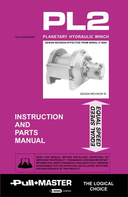
<strong>PL2</strong><br />
THE INTRAVENT<br />
PLANETARY HYDRAULIC WINCH<br />
DESIGN REVISION EFFECTIVE FROM SERIAL # 76061<br />
DESIGN REVISION ‘B’<br />
INSTRUCTION<br />
AND<br />
PARTS<br />
MANUAL<br />
READ THIS MANUAL BEFORE INSTALLING, OPERATING OR<br />
SERVICING THIS PRODUCT. THIS MANUAL CONTAINS IMPORTANT<br />
INFORMATION. MAKE THIS MANUAL AVAILABLE TO ALL PERSONS<br />
RESPONSIBLE FOR THE OPERATION, INSTALLATION, SERVICING<br />
AND MAINTENANCE OF THIS PRODUCT.<br />
THE LOGICAL<br />
CHOICE
Effective 2011/10/01<br />
SUPERSEDES ALL PRIOR WARRANTIES<br />
LIMITED WARRANTY 50130-0<br />
Seller warrants that each article (whether Gear Drive Products, Brake Products and/or Winch Products, all of which are covered<br />
hereunder) sold under this order shall at the time of shipment (i) conform to applicable specifications, and (ii) be free from<br />
defects in material and workmanship during normal and ordinary use and service (the "Warranty").<br />
Buyer's exclusive remedy and Seller's sole obligation under this Warranty shall be, at Seller's option, to repair or replace any<br />
article or part thereof which has proven to be defective, or to refund the purchase price of such article or part thereof. Buyer<br />
acknowledges that Buyer is knowledgeable concerning the articles covered by this Warranty and sold in connection therewith<br />
which are being purchased, that Buyer has reviewed this Warranty and that the remedies provided hereunder are adequate<br />
and acceptable to Buyer.<br />
This Warranty shall expire one (1) year from the date the article is first shipped by Seller. Notice of claimed breach of this<br />
Warranty must be given by Buyer to Seller within the applicable period. Such notice shall include an explanation of the claimed<br />
warranty defect and proof of date of purchase of the article or part thereof for which warranty coverage is sought. No<br />
allowances shall be made by Seller for any transportation, labor charges, parts, "in and out" costs, adjustments or repairs, or<br />
any other work, unless such items are authorized in writing and in advance by Seller. Nor shall Seller have any obligation to<br />
repair or replace items which by their nature are expendable.<br />
If an article is claimed to be defective in material or workmanship, or not to conform to the applicable specifications, Seller will<br />
either examine the article at Buyer's site or issue shipping instructions for return to Seller. This Warranty shall not extend to any<br />
articles or parts thereof which have been installed, used, or serviced otherwise than in conformity with Seller's applicable<br />
specifications, manuals, bulletins, or instructions, or which shall have been subjected to improper installation, operation, or<br />
usage, misapplication, neglect, incorrect installation, overloading, or employment for other than normal and ordinary use and<br />
service. This Warranty shall not apply to any article which has been repaired, altered or disassembled, or assembled by<br />
personnel other than those of Seller. This Warranty shall not apply to any article upon which repairs or alterations have been<br />
made (unless authorized in writing and in advance by Seller). This Warranty shall not apply to any articles or parts thereof<br />
furnished by Seller to Buyer's specifications and/or furnished by Buyer or acquired from others at Buyer's request.<br />
SELLER MAKES NO EXPRESS WARRANTIES AND NO IMPLIED WARRANTIES OF ANY KIND, OTHER THAN THE<br />
WARRANTY EXPRESSLY SET FORTH ABOVE. SUCH WARRANTY IS EXCLUSIVE AND IS MADE AND ACCEPTED IN<br />
LIEU OF ANY AND ALL OTHER WARRANTIES, EXPRESS OR IMPLIED, INCLUDING WITHOUT LIMITATION THE IMPLIED<br />
WARRANTIES OF MERCHANTABILITY AND FITNESS FOR A PARTICULAR PURPOSE.<br />
Buyer expressly agrees that Seller is not responsible to perform any work or investigation related in any way to torsional<br />
vibration issues and is not responsible for the detection or remedy of Natural Frequency Vibration of the mechanical system in<br />
which the unit is installed. Buyer acknowledges, understands and agrees that this Warranty does not cover failures of the unit<br />
which result in any manner from the operation of the machine or unit at vibration frequencies at or near the natural frequency<br />
vibration of the machine in such a way that damage may result. Buyer expressly agrees that Seller is not responsible for failure<br />
damage or accelerated wear caused by machine or ambient vibration. Further, Buyer acknowledges and agrees that Buyer is<br />
always solely responsible for determination and final approval of the “application factor” which may be used in Seller’s<br />
calculations and this application factor is 1.0 unless otherwise stated in Seller’s quotation specifications.<br />
The remedies for this Warranty shall be only those expressly set forth above, to the exclusion of any and all other remedies of<br />
whatsoever kind. The limited remedies set forth above shall be deemed exclusive, even though they may fail their essential<br />
purpose. No agreement varying or extending the foregoing Warranty, remedies, exclusions, or limitations shall be effective<br />
unless in writing signed by an executive officer of Seller and Buyer. This Warranty is non-transferable. If a party who had<br />
purchased articles from Buyer, or from persons in privity with Buyer, brings any action or proceeding against Seller for<br />
remedies other than those set forth in this Warranty, Buyer agrees to defend Seller against the claims asserted in such action<br />
or proceeding at Buyer’s expense, including the payment of attorneys’ fees and costs, and indemnify Seller and hold Seller<br />
harmless of, from and against all such claims, actions, proceedings or judgments therein. Buyer also agrees to defend and<br />
indemnify Seller of, from and against any loss, cost, damage, claim, debt or expenses, including attorneys’ fees, resulting from<br />
any claims by Buyer or third parties to property or injury to persons resulting from faulty installation, repair or modification of the<br />
article and misuse or negligent operation or use of the article, whether or not such damage to property or injury to persons may<br />
be caused by defective material, workmanship, or construction.<br />
ADVISORY: Winches and hoists are not approved for lifting or handling personnel or persons unless specifically approved in<br />
writing from Seller for the specific intended application.<br />
Under no circumstances shall Seller be liable (i) for any damage or loss to any property other than the warranted article or part<br />
thereof, or (ii) for any special, indirect, incidental, or consequential damage or loss, even though such expenses, damages, or<br />
losses may be foreseeable.<br />
The foregoing limitations on Seller's liability in the event of breach of warranty shall also be the absolute limit of Seller's liability<br />
in the event of Seller's negligence in manufacture, installation, or otherwise, with regard to the articles covered by this<br />
Warranty, and at the expiration of the Warranty period as above stated, all such liabilities shall terminate. Buyer’s purchase of<br />
any article(s) covered by this Warranty shall constitute acceptance of the terms and conditions hereof and shall be binding<br />
upon Buyer and Buyer’s representatives, heirs and assigns. The laws of the Province of British Columbia shall govern Buyer’s<br />
rights and responsibilities in regard to this Warranty and the transaction(s) subject thereto, and the Province of British Columbia<br />
shall be the exclusive forum and jurisdiction for any action or proceedings brought by Buyer in connection herewith or any<br />
dispute hereunder. If any of the terms and conditions contained within this Warranty are void, the remaining provisions thereof<br />
are and shall remain valid and enforceable.
SAFETY RECOMMENDATIONS<br />
DANGER<br />
FAILURE TO COMPLY WITH THE FOLLOWING SAFETY<br />
RECOMMENDATIONS AND LOCAL RULES AND<br />
REGULATIONS WILL RESULT IN PROPERTY<br />
DAMAGE, SEVERE INJURY OR DEATH.<br />
Definition: Caution indicates a potentially<br />
hazardous situation which, if not avoided may<br />
result in minor or moderate injury.<br />
Definition: Warning indicates a potentially<br />
hazardous situation which, if not avoided could<br />
result in death or serious injury.<br />
Definition: Danger indicates a potentially<br />
hazardous situation which, if not avoided will<br />
result in death or serious injury.<br />
The planetary hydraulic winches are made for hoisting and lowering loads and to be operated by trained and professional personnel. They<br />
are not designed for operations involving lifting or moving personnel. The winches are powered by hydraulic power. The ropes / cables<br />
for hoisting operations are not supplied by PULLMASTER. The winches are always assembled in an application, they do not function<br />
as an independent machine and it is not allowed to use them as such.<br />
The winches are to be used within the specifications as listed in the manual under “SPECIFICATIONS”. Other use as foreseen in the<br />
functional description of the hydraulic winch is not allowed without written permission from PULLMASTER.<br />
1. Do not install, operate or service winch before<br />
reading and understanding manufacturer's<br />
instructions.<br />
2. The winch described herein is not designed for<br />
operations involving lifting or moving personnel.<br />
3. Do not lift or carry loads over people.<br />
4. Do not exceed recommended operating<br />
pressure (psi) and operating volume (gpm).<br />
5. Do not jerk the winch. Always smoothly<br />
accelerate and decelerate load.<br />
6. Do not operate a damaged, noisy or<br />
malfunctioning winch.<br />
7. Do not leave a load suspended for any<br />
extended period of time.<br />
8. Never leave a suspended load unattended.<br />
9. Winch should be maintained and operated by<br />
qualified personnel.<br />
10. Inspect winch, rigging, mounting bolts and<br />
hoses before each shift.<br />
11. Warm-up equipment before operating winch,<br />
particularly at low ambient temperatures.<br />
12. Verify winch function by raising and lowering a<br />
full test load to a safe height before each shift.<br />
13. Do not weld any part of the winch.<br />
14. Verify gear lubrication and brake circulation<br />
supply and return before operating winch.<br />
15. Be sure of equipment stability before operating<br />
winch.<br />
16. Wear proper clothing to avoid entanglement in<br />
rotating machinery.<br />
17. Always stand clear of the load.<br />
18. Use only recommended hydraulic oil and gear<br />
lubricant.<br />
19. Keep hydraulic system clean and free from<br />
contamination at all times.<br />
20. Maintain winch and equipment in good operating<br />
condition. Perform scheduled maintenance regularly.<br />
21. Keep hands clear when winding wire rope onto<br />
the winch drum.<br />
22. Do not use the wire rope as a ground for welding.<br />
23. Rig the winch carefully. Ensure that the wire<br />
rope is properly anchored to the correct cable anchor<br />
slot at the cable drum.<br />
24. Do not lift a load with a twisted, kinked or<br />
damaged wire rope.<br />
25. Consult wire rope manufacturer for size, type and<br />
maintenance of wire rope.<br />
26. Maintain five wraps of wire rope on the cable<br />
drum at all times.<br />
27. In case of a power failure or breakdown leading<br />
to an unexpected stop of the hydraulic power circuit,<br />
stand clear of the area and the load being hoisted,<br />
take the necessary precautions to prevent access to<br />
area where the load is halted.<br />
28. The noise level of the winch is 90 dBA measured<br />
on a distance of 1.00 meter, 1.60 meters high. The<br />
measuring equipment used was: Realistic #42-3019.<br />
29. Clean up any oil spillage immediately.<br />
30. Wear proper clothing and personal protection<br />
equipment such as, footwear, safety goggles and a<br />
hard hat. Read manual first.<br />
315 REV.051117<br />
PAGE 1
DESCRIPTION OF THE MODEL <strong>PL2</strong><br />
GENERAL DESCRIPTION:<br />
The PULLMASTER <strong>Model</strong> <strong>PL2</strong> is a planetary hydraulic winch having equal speed in both directions.<br />
The main components of this unit are:<br />
✛<br />
✛<br />
✛<br />
✛<br />
✛<br />
✛<br />
✛<br />
✛<br />
Hydraulic gear motor<br />
Multi disc brake with static and dynamic function<br />
Over-running clutch<br />
Primary planet reduction<br />
Final planet reduction<br />
Brake housing<br />
End housing<br />
Cable drum<br />
FUNCTION IN FORWARD ROTATION (HOISTING):<br />
In forward rotation, the output torque and rpm of the hydraulic motor are transmitted to the sungear<br />
of the primary planet reduction. The output of the primary reduction is transferred to the final sungear,<br />
which is splined to the primary planet hub. The final planet assembly does not rotate, so the rotation<br />
is transmitted to the cable drum by the final drive planet gears. In forward rotation, or when a load<br />
is lifted, an over-running clutch, which connects the motor drive shaft to the automatic brake assembly,<br />
permits free rotation of the sungear, without effecting the brake. Pressure required to rotate the drum<br />
at full speed without load may vary up to 450 psi (31 bar). When the winch rotation is stopped, the<br />
load on the cable drum causes the over-running clutch to lock and the maximum load is held safely<br />
by the disc brake.<br />
FUNCTION IN REVERSE ROTATION (LOWERING):<br />
In reverse rotation, or when the winch is pressurized for lowering a load, hydraulic pressure from the<br />
reverse side of the hydraulic motor is channelled to the brake piston, causing the brake piston to<br />
release the multi-disc brake against a number of brake springs. The pressure required to rotate the<br />
drum at full speed may vary from 200 - 500 psi (14 - 34 bar) depending upon load and from 550 -<br />
1075 psi (38 - 74 bar) without load. The over-running clutch, connecting the motor drive shaft to the<br />
brake assembly, locks, causing the brake discs to rotate between divider plates, which are engaged<br />
into the brake housing. If the load on the cable drum tends to effect the lowering speed, the resulting<br />
pressure drop in the brake piston causes friction between the brake discs and the divider plates. In<br />
this way, a completely smooth paying out speed can be achieved in a stepless operation by<br />
modulation of the winch control handle. When the control handle is returned to neutral position,<br />
rotation stops and the disc brake applies automatically. A hydraulic counter-balance valve or holding<br />
valve is not required for smooth and positive operation of the automatic brake.<br />
During the lowering operation of the winch, the friction created by the brake discs results in heat. This<br />
heat is dissipated by the circulation of hydraulic fluid through the brake housing, supplied internally<br />
through the hydraulic motor. This circulation flow is internally vented to the return line flow through<br />
a check valve arrangement inside the hydraulic motor. The circulation flow is supplied only when a<br />
load is lowered. A separate vent line connecting the PULLMASTER <strong>Model</strong> <strong>PL2</strong> with the hydraulic<br />
reservoir is not normally required.<br />
(See TYPICAL HYDRAULIC CIRCUITS.)<br />
IMPORTANT:<br />
Pressure in the brake housing must never exceed 100 psi (7 bar). Excessive brake<br />
housing pressure will cause the safety valve located on top of the motor to leak.<br />
Brake housing pressure can be gauged at the safety valve port.<br />
PAGE 2<br />
315 REV.990607
EXPLANATION OF MODEL CODING<br />
PL 2 X - XX - XX - XX X - B XXXX<br />
BASIC UNIT SERIES<br />
SIZE OF UNIT<br />
REDUCTION RATIO<br />
Only used for non-standard reduction ratios<br />
TYPE OF BRAKE<br />
-12 Automatic brake, counterclockwise hoisting, intravent<br />
-13 Automatic brake, external brake release, counterclockwise hoisting,<br />
intravent<br />
-14 Automatic brake, external brake release, clockwise hoisting, intravent<br />
-15 Automatic brake, clockwise hoisting, intravent<br />
-16 Automatic brake, counterclockwise hoisting, intravent,<br />
external brake release<br />
-17 Automatic brake, effective in both directions, external brake release,<br />
external circulation, external drain port<br />
-18 Automatic brake, effective in both directions, intravent<br />
-19 Automatic brake, external brake release, zero leakage,<br />
counterclockwise hoisting, intravent<br />
-20 Automatic brake, external brake release, zero leakage,<br />
clockwise hoisting, intravent<br />
HYDRAULIC MOTOR<br />
-228 Gear motor (.81 cubic inch displacement)<br />
(Other motors are optional)<br />
DRUM SIZE<br />
-1 6.13 inch drum diameter x 9.00 inch flange diameter x 5.25 inch length - STANDARD<br />
(For other drum sizes refer to APPENDIX A)<br />
OPTIONS<br />
DESIGN REVISION *<br />
SPECIFICATION NUMBER<br />
Describes features not identified by preceding codes<br />
NOTE:<br />
Clockwise and counterclockwise drum rotation is the direction of rotation for pulling or hoisting,<br />
established by looking at the hydraulic motor.<br />
DESIGN REVISION EFFECTIVE FROM SERIAL # 76061<br />
315 REV.081208<br />
PAGE 3
OPTIONS<br />
CLOCKWISE ROTATION:<br />
The drum rotation of the standard PULLMASTER <strong>Model</strong> <strong>PL2</strong> planetary winch is counterclockwise for hoisting, when<br />
looking at the hydraulic motor of the winch. Drum rotation for clockwise hoisting direction is available as an option.<br />
EXTERNAL BRAKE RELEASE:<br />
PULLMASTER planetary winches can be supplied with an external brake release which permits release of the<br />
automatic disc brake from an external pressure source.<br />
DANGER<br />
FAILURE TO PROPERLY VENT EXTERNAL BRAKE RELEASE PORT WILL<br />
TRAP BRAKE PRESSURE AND ALLOW THE LOAD TO DROP,<br />
CAUSING PROPERTY DAMAGE, SEVERE INJURY OR DEATH.<br />
WINCHES SUPPLIED WITH EXTERNAL BRAKE RELEASE OPTION<br />
MUST BE CONNECTED ACCORDING TO "TYPICAL HYDRAULIC CIRCUIT".<br />
CABLE DRUM SIZES:<br />
Aside from the standard drum sizes listed in APPENDIX A, the PULLMASTER <strong>Model</strong> <strong>PL2</strong> planetary<br />
winch can be supplied with optional drums to accommodate large wire rope storage capacity.<br />
DRUM GROOVING:<br />
Cable drums for the PULLMASTER <strong>Model</strong> <strong>PL2</strong> planetary winch can be grooved. Where this option is<br />
a requirement, it is necessary to state the size of wire rope which is to be used with the winch.<br />
OPTIONAL GEAR SECTION FOR THE HYDRAULIC MOTOR:<br />
The performance of the standard PULLMASTER <strong>Model</strong> <strong>PL2</strong> planetary winch may be changed by using<br />
a different displacement motor.<br />
(Contact the factory for performance information.)<br />
HYDRAULIC MOTORS FOR HIGH PRESSURE HYDRAULIC SYSTEMS:<br />
The operating pressure of the PULLMASTER <strong>Model</strong> <strong>PL2</strong> planetary winch is limited to 2200 psi (152<br />
bar). For hydraulic systems operating with higher hydraulic pressure, the winch can be supplied with<br />
a hydraulic piston motor, which will provide for the same basic performance in terms of line pull and line<br />
speed capacity.<br />
(Contact the factory for this requirement.)<br />
The PULLMASTER WINCH CORPORATION will consider other options for quantity requirements.<br />
PAGE 4<br />
315 REV.990607
SPECIFICATIONS<br />
Performance specifications are based on standard hydraulic motor, gear ratio and cable drum with<br />
5/16 inch diameter wire rope. For other cable drums and gear ratios refer to APPENDIX A. Performance<br />
specifications for winches supplied with optional motors are provided in attached supplement.<br />
CABLE DRUM DIMENSIONS (STANDARD DRUM):<br />
Barrel diameter 6.13 in 156 mm<br />
Flange diameter 9.00 in 229 mm<br />
Barrel length 5.25 in 133 mm<br />
CABLE STORAGE CAPACITY:<br />
Size of wire rope 1/4 in 172 ft 52 m<br />
5/16 in 122 ft 37 m<br />
3/8 in 84 ft 25 m<br />
MAXIMUM OPERATING PRESSURE: 2200 psi 152 bar<br />
MAXIMUM OPERATING VOLUME: 7.7 (US) gpm 29 l/min<br />
MINIMUM OPERATING VOLUME: 2.5 (US) gpm 9 l/min<br />
DRUM TORQUE AT MAXIMUM PRESSURE: 7095 lb-in 802 Nm<br />
DRUM RPM AT MAXIMUM VOLUME:<br />
49 rpm<br />
LINE PULL AT MAXIMUM PRESSURE:<br />
Bare drum 2204 lb 9.8 kN<br />
Full drum 1633 lb 7.3 kN<br />
LINE SPEED AT MAXIMUM VOLUME:<br />
Bare drum 83 fpm 25 m/min<br />
Full drum 111 fpm 34 m/min<br />
PERMISSIBLE SYSTEM BACK PRESSURE AT<br />
MOTOR RETURN PORT: 65 psi 4.5 bar<br />
PERMISSIBLE PRESSURE AT<br />
BRAKE HOUSING SAFETY VALVE: 100 psi 7 bar<br />
LUBRICATING OIL:<br />
Refer to RECOMMENDATIONS for viscosity and instructions.<br />
Refer to APPENDIX A for oil volume required.<br />
315 REV.050722<br />
PAGE 5
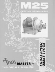
PERFORMANCE GRAPHS<br />
LINE PULL VS. OIL PRESSURE<br />
PG-<strong>PL2</strong>-B<br />
2200<br />
LINE PULL - kN<br />
0 1.8 3.6 5.3 7.1 8.9 10.7<br />
152<br />
2000 138<br />
OIL PRESSURE - psi<br />
1500 103<br />
1000 69<br />
500 35<br />
FULL DRUM<br />
BARE DRUM<br />
OIL PRESSURE - bar<br />
0<br />
0<br />
400<br />
800<br />
1200<br />
LINE PULL - lb<br />
1600<br />
2000<br />
2400<br />
0<br />
LINE SPEED VS. OIL VOLUME<br />
LINE SPEED - m/min<br />
7.7<br />
0 3 6 9 12 15 18 21 24 27 31 34<br />
29<br />
OIL VOLUME - (US)gpm<br />
7.0<br />
6.0<br />
5.0<br />
4.0<br />
3.0<br />
2.0<br />
1.0<br />
BARE DRUM<br />
FULL DRUM<br />
26<br />
23<br />
19<br />
15<br />
11<br />
8<br />
4<br />
OIL VOLUME - l/min<br />
0<br />
0 10 20 30 40 50 60 70 80 90 100 110<br />
LINE SPEED - fpm<br />
0<br />
Performance graphs are based on standard hydraulic motor, gear ratio and cable drum with 1/4<br />
inch diameter rope.<br />
PAGE 6<br />
315 REV.990607
TYPICAL HYDRAULIC CIRCUITS<br />
HC-<strong>PL2</strong>-S1<br />
PRESSURE<br />
RELIEF VALVE<br />
800 PSI [55 BAR]<br />
2(US)GPM [8 L/MIN]<br />
REQUIRED FOR MODELS<br />
SUPPLIED WITH EXTERNAL<br />
BRAKE RELEASE OPTION<br />
HYDRAULIC<br />
PUMP<br />
RESERVOIR<br />
FILTER<br />
WINCH CONTROL<br />
VALVE<br />
(MOTOR SPOOL)<br />
4-WAY SPRING<br />
RETURN TO<br />
CENTER<br />
1. TYPICAL HYDRAULIC CIRCUIT - STANDARD CONTROL VALVE<br />
Refer to above hydraulic circuit for installations where the winch is controlled by an individual control<br />
valve. Note that the valve must have a “motor spool” (both winch ports open to tank in neutral<br />
position). A motor drain line is not required.<br />
CONTROL VALVE STACK<br />
WINCH CONTROL<br />
VALVE<br />
(MOTOR SPOOL +<br />
POWER BEYOND)<br />
2. TYPICAL HYDRAULIC CIRCUIT - POWER BEYOND CONTROL VALVE<br />
Refer to above hydraulic circuit when the winch control valve is used in a circuit containing stacked<br />
valves controlling other functions, as occurs on hydraulic cranes and loaders. The winch control<br />
valve must have a “motor spool” and “power beyond” feature. The winch valve is shown upstream<br />
of the stacked control valves. If the winch control valve is located downstream of the stacked control<br />
valves, the valve stack must have the “power beyond” feature. A motor drain line is not required.<br />
315 REV.020730<br />
PAGE 7
TYPICAL HYDRAULIC CIRCUITS CONTINUED<br />
HC-<strong>PL2</strong>-S1<br />
CONTROL VALVE STACK<br />
MOTOR DRAIN LINE<br />
(MUST GO DIRECT<br />
TO RESERVOIR)<br />
WINCH CONTROL<br />
VALVE<br />
(CYLINDER SPOOL)<br />
3. TYPICAL HYDRAULIC CIRCUIT - STACKED CONTROL VALVE<br />
Refer to above hydraulic circuit when the winch control valve is one of several stacked control<br />
valves and has a “cylinder spool” (winch ports blocked in neutral position). In this configuration,<br />
the safety valve must be replaced with a drain line plumbed directly to the reservoir. The drain<br />
line cannot be connected to a common return line.<br />
IMPORTANT:<br />
For proper function of the winch in any circuit, the return line back pressure measured<br />
at the motor return port and the brake housing pressure measured at the safety valve<br />
must not exceed pressures per SPECIFICATIONS.<br />
PAGE 8<br />
315 REV.990607
RECOMMENDATIONS<br />
HYDRAULIC FLUID:<br />
The hydraulic fluid selected for use with<br />
PULLMASTER planetary winches should be a<br />
high grade, petroleum based fluid with rust, oxidation<br />
and wear resistance. Fluid cleanliness and<br />
operating viscosity are critical to winch reliability,<br />
efficiency and service life.<br />
For optimum performance, the recommended<br />
viscosity range at operating temperature is 81 - 167<br />
SUS (16 - 36 CS). For extreme operating conditions<br />
of short duration, the maximum viscosity range of<br />
58 - 4635 SUS (10 - 1000 CS) should not be<br />
exceeded.<br />
The winch recommended hydraulic fluid<br />
temperature operating range is 80 - 150F (27 -<br />
66C). For extreme operating conditions of short<br />
duration, the maximum temperature range of -5 -<br />
180F (-21 - 82C) should not be exceeded.<br />
LUBRICATION:<br />
The winch gear train requires oil bath lubrication.<br />
The winch is shipped from the factory without<br />
lubricating oil.<br />
IMPORTANT: ADD LUBRICATING OIL UP TO THE<br />
LEVEL OF THE END HOUSING OIL<br />
FILL PORT BEFORE RUNNING<br />
WINCH.<br />
Refer to INSTALATION DIMENSIONS for location<br />
of lubricating oil fill port. Refer to APPENDIX A for<br />
quantity of oil required. SAE 90 lubricating oil is<br />
recommended. Consult lubricating oil supplier or<br />
factory for temperature beyond normal operating<br />
range.<br />
HYDRAULIC PUMP:<br />
For maximum performance of the PULLMASTER<br />
planetary winch the hydraulic pump must supply<br />
the maximum flow of hydraulic fluid at the hydraulic<br />
pressure stated in SPECIFICATIONS.<br />
HYDRAULIC CONTROL VALVE:<br />
The standard control valve used for operating<br />
PULLMASTER planetary winches must have a<br />
four-way, spring return to neutral feature, which<br />
provides for open flow from the pressure ports of<br />
the winch to the reservoir in neutral position of the<br />
control (motor spool). It is important to point out that<br />
good speed control, especially when lowering a<br />
load, depends on the “metering” characteristics of<br />
the control valve. The better the oil flow is “metered”,<br />
the better will be the speed control.<br />
315 REV.030106<br />
HYDRAULIC PRESSURE RELIEF:<br />
The hydraulic circuit for the PULLMASTER<br />
planetary winch requires a pressure relief set at the<br />
operating pressure (see SPECIFICATIONS).<br />
Usually, a pressure relief is part of the hydraulic<br />
control valve. Where this is not the case, a separate<br />
pressure relief valve must be installed and set at<br />
the recommended maximum pressure.<br />
HYDRAULIC RESERVOIR:<br />
It is recommended that the hydraulic reservoir has<br />
sufficient capacity to provide good heat dissipation<br />
in order to prevent over-heating of the hydraulic<br />
fluid. The hydraulic reservoir should be made from<br />
clean and scale-free material to prevent<br />
contamination of the hydraulic fluid. In order to<br />
prevent air from being mixed with the hydraulic<br />
fluid, the reservoir should have an over-flow baffle<br />
separating the return lines from the suction line and<br />
all return lines should enter the reservoir below the<br />
fluid level. The reservoir should be mounted close<br />
to and above the hydraulic pump in a location<br />
which provides for free air circulation around the<br />
reservoir.<br />
HYDRAULIC FILTER:<br />
Consult hydraulic component manufacturer for<br />
recommendation. Generally, 5 to 10 micron filters<br />
are acceptable. In order to prevent accidental<br />
stoppage of the return line flow, the filter should<br />
have a by-pass feature.<br />
HYDRAULIC HOSES:<br />
The following hydraulic hose with suitable fittings<br />
is recommended for the PULLMASTER <strong>Model</strong> <strong>PL2</strong><br />
planetary winch.<br />
Pressure lines:<br />
Motor drain line<br />
(when required):<br />
SAE 100R2-8 or better<br />
SAE 100R6-4 or better<br />
It is recommended that larger hydraulic hose be<br />
installed where pressure lines are excessively<br />
long.<br />
USE OF AN E STOP:<br />
(FOR EUROPEAN MACHINERY DIRECTIVE<br />
APPLICATIONS)<br />
The use of an E stop (emergency) is mandatory in<br />
the controls circuit. The E stop is to be placed in the<br />
operator’s control panel. The E stop must be<br />
designed and placed in line with EN 60204 and EN<br />
418.<br />
PAGE 9
INSTALLATION INSTRUCTIONS<br />
DANGER<br />
FAILURE TO FOLLOW INSTALLATION INSTRUCTIONS<br />
WILL RESULT IN PROPERTY DAMAGE,<br />
SEVERE INJURY OR DEATH.<br />
The initial installation or mounting of a PULLMASTER planetary winch is critically important for proper<br />
operation and performance. If the winch is mounted to an uneven surface, the centre line of the unit<br />
can be distorted to a point where the winch will not operate in either direction. It is therefore very important<br />
that the following instructions are observed when a PULLMASTER planetary winch is installed:<br />
1) Make certain that the mounting platform is sufficiently strong in order to avoid deflection when a<br />
load is lifted.<br />
2) Set the winch on the mounting platform and check for surface contact on all mounting pads of<br />
the winch.<br />
3) If there is a space between the mounting surface and one of the mounting pads, the mounting<br />
surface is not even and the space below the mounting pad must be shimmed. If this condition<br />
exists, proceed as follows:<br />
a) Install mounting bolts snug tight on the three mounting pads which are in contact with the<br />
mounting surface. For mounting bolt size and grade, see INSTALLATION DIMENSIONS.<br />
b) Measure the space underneath the fourth mounting pad with a feeler gauge and use shim stock<br />
of equivalent thickness in the space between the mounting pad and the mounting surface.<br />
c) Only after this procedure, should the fourth mounting bolt be installed. Tighten all four bolts<br />
as per torque chart at back of manual.<br />
4) Fill the winch with lubricating oil. See APPENDIX A for oil volume required.<br />
5) Use recommended circuit components and hydraulic hoses.<br />
6) When required, the winch motor drain line must be connected directly to the reservoir. Do not<br />
connect to a common return line.<br />
IMPORTANT:<br />
Excessive pressure at brake housing will damage the winch motor or oil seals. Never<br />
plug safety valve port. Higher pressure inside the brake housing requires higher brake<br />
release pressure to rotate the drum in the lowering direction.<br />
7) Before operating the winch with a load, verify that hydraulic fluid is circulating through the brake<br />
assembly by removing the safety valve and checking flow when the winch is run in the lowering<br />
direction. Flow should measure 3/4 - 1 gpm (3 - 4 l/min).<br />
NOTE:<br />
Pressure required to rotate the drum in forward direction at full speed without load may<br />
vary up to 450 psi (31 bar).<br />
Pressure required to rotate the drum in reverse direction at full speed may vary from<br />
200 - 500 psi (14 - 34 bar) depending upon load and from 550 - 1075 psi (38 - 74 bar)<br />
without load.<br />
PAGE 10<br />
315 REV.990607
OPERATING INSTRUCTIONS<br />
DANGER<br />
FAILURE TO FOLLOW OPERATING INSTRUCTIONS WILL<br />
RESULT IN PROPERTY DAMAGE, SEVERE INJURY OR DEATH.<br />
After the PULLMASTER planetary winch has been installed in accordance with the INSTALLATION<br />
INSTRUCTIONS, the wire rope can be fastened to the cable drum.<br />
IMPORTANT:<br />
The ropes, chains, slings, etc. are not part of the winch and are not covered by this<br />
manual. Refer to manufacturer’s handling, inspection and maintenance<br />
recommendations to avoid potential accidents. For selection of ropes, etc. please<br />
check following product standards: DIN 15020, prEN818-1/9, prEN 1492-1/2, prEN<br />
1677-1/3 and other relevant product standards.<br />
1) The cable drum of the PULLMASTER planetary winch has two cable anchor slots, one for clockwise<br />
and one for counterclockwise hoisting. Standard rotation for hoisting is counterclockwise when<br />
looking at the hydraulic motor of the unit. It is critical to select the cable anchor slot which will permit<br />
winding of the wire rope on the drum in the correct direction of rotation. If the wire rope is wound<br />
on the cable drum in the wrong direction of rotation, the winch will have no braking capacity. Each<br />
winch is shipped from the factory with a label on the drum, indicating the correct cable anchor slot.<br />
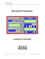
WIRE ROPE INSTALLATION<br />
Counterclockwise hoisting winch shown.<br />
(Use cable anchor slot on opposite side of<br />
drum for clockwise hoisting winch.)<br />
Feed the wire rope through the cable anchor<br />
slot. Loop rope back into slot as shown.<br />
Insert cable anchor into slot, small end first<br />
and long side nearest the drum flange. Pull<br />
rope tight to wedge rope in slot.<br />
SI1013 - <strong>PL2</strong><br />
CABLE ANCHOR SLOT<br />
CABLE ANCHOR<br />
2) On wire rope installation, care must be taken that the wire rope is wrapped completely around the<br />
cable anchor and properly pulled into the cable anchor slot in the cable drum. The cable drum<br />
requires minimum 5 wraps of wire rope for safety.<br />
3) The winch operation is controlled by a single control valve lever which has a forward, a reverse<br />
and a neutral position. Speed control in either direction is obtained by modulation of the control<br />
valve lever. Maximum line speed in either direction is obtained when the control valve lever is moved<br />
as far as it can go. The disc brake of the winch will come on automatically when the winch control<br />
lever is returned to neutral.<br />
4) Always warm up equipment prior to operating winch, particularly in low ambient temperature.<br />
Circulate hydraulic oil through the winch control valve for several minutes to warm the hydraulic<br />
systems. To prime the winch with warm oil, operate the winch at slow speed, forward and reverse,<br />
several times.<br />
5) To ensure proper winch installation and function, raise and lower a full test load to a safe height<br />
before using winch for regular operation at the start of each shift.<br />
If, after a new installation, the winch does not function properly, refer to the TROUBLESHOOTING<br />
section of this manual.<br />
315 REV.051117<br />
PAGE 11
TROUBLE SHOOTING<br />
GENERAL:<br />
In most cases, when the hydraulic winch does not perform satisfactorily, the cause for malfunction is<br />
found somewhere in the hydraulic circuit. Before the winch is removed from its mounting and<br />
disassembled, all of the hydraulic circuit components should be checked for proper function.<br />
IMPORTANT:<br />
The hydraulic oil volume relates to the line speed or rpm of the winch.<br />
Therefore, if the winch does not produce the specified maximum rated line speed or drum rpm, a loss<br />
of hydraulic flow somewhere in the hydraulic circuit can be analysed. If this condition exists, install<br />
a flow meter into the hydraulic circuit to check the volume of oil supplied to the pressure port of the<br />
hydraulic winch motor when the winch control is completely opened. The flow meter should indicate<br />
the maximum operating volume. If this test indicates a loss of hydraulic flow, check the hydraulic pump,<br />
the relief valve and the control valve. If the pump is driven by V-belts, check for belt slippage.<br />
The hydraulic pressure relates to the pulling capacity of the winch.<br />
If the winch will not produce the specified maximum line pull, install a pressure gauge in the pressure<br />
line leading to the hoisting port on the hydraulic winch motor. Stall the winch to prevent rotation of<br />
the drum and then open the control valve. Check the hydraulic pressure reading of the installed<br />
pressure gauge. If the pressure reads below the specified maximum operating pressure, look for<br />
trouble in the hydraulic pump, the relief valve and the control valve. If the hydraulic pump is driven<br />
by V-belts, check for belt slippage. When checking oil pressure and volume in the hydraulic circuit,<br />
verify that the hydraulic reservoir is filled to the top level and the hydraulic pump is running at maximum<br />
operating rpm.<br />
Only after the hydraulic system has been checked and found to be in order, use the following indications<br />
for probable causes of failure in the winch:<br />
Winch will not produce line speed at maximum<br />
volume as listed in SPECIFICATIONS.<br />
Winch will not reverse.<br />
FAILURE<br />
Winch will not produce line pull at maximum<br />
pressure as listed in SPECIFICATIONS.<br />
PROBABLE CAUSE<br />
a) Winch is mounted to an uneven surface.<br />
(See INSTALLATION INSTRUCTIONS.)<br />
b) Cable sheaves or block purchase operated with the<br />
winch are not turning freely.<br />
c) Damage or wear in the hydraulic motor.<br />
d) The relief valve pressure may be set too low.<br />
(See SPECIFICATIONS for maximum operating pressure.)<br />
e) Excessive back pressure in the hydraulic circuit<br />
a) Winch is mounted to an uneven surface.<br />
(See INSTALLATION INSTRUCTIONS.)<br />
b) Cable sheaves or block purchase operated with the<br />
winch are not turning freely.<br />
c) Damage or wear in the hydraulic motor.<br />
d) Excessive back pressure in the hydraulic circuit.<br />
a) Leakage out of the brake piston prevents the disc<br />
brake from being released against the brake springs.<br />
This is caused by damage to the O-rings on the brake<br />
piston or connecting tube.<br />
b) Insufficient hydraulic pressure.<br />
(See SPECIFICATIONS for minimum operating pressure.)<br />
c) Winch is mounted to an uneven surface.<br />
(See INSTALLATION INSTRUCTIONS.)<br />
d) Hydraulic pressure is not reaching the brake piston<br />
due to plugged connecting tube.<br />
PAGE 12<br />
315 REV.990607
TROUBLE SHOOTING CONTINUED<br />
FAILURE<br />
Brake will not hold.<br />
Brake vibrates when lowering a load.<br />
Oil leaks.<br />
PROBABLE CAUSE<br />
a) Brake plates or divider plates have been damaged by<br />
contamination in the hydraulic fluid or lack of circulation<br />
flow in the brake housing.<br />
b) Brake piston is seized in the brake housing because<br />
of contamination in the hydraulic fluid.<br />
c) Excessive back pressure in the return line of the<br />
hydraulic circuit causes the brake to release.<br />
d) Control valve has incorrect spool which traps hydraulic<br />
pressure in the brake piston when the control valve<br />
handle is returned to neutral position. For proper<br />
function of the automatic brake, both pressure ports<br />
of the winch must be open to the reservoir in neutral<br />
position of the control valve.<br />
e) Wire rope is fastened to the incorrect cable anchor slot.<br />
f) Over-running clutch is damaged or surface where overrunning<br />
clutch engages on motor drive shaft is worn or<br />
indented.<br />
g) Winch supplied with external brake release option is not<br />
plumbed per TYPICAL HYDRAULIC CIRCUITS. Failure<br />
to vent external brake release port to reservoir may trap<br />
pressure and cause winch brake to slip.<br />
a) Pump does not supply sufficient flow. Pump rpm must<br />
be maintained at normal operating speed when a load<br />
is lowered.<br />
b) Brake is running too hot. This is caused by a complete<br />
lack of, or insufficient, circulation flow.<br />
c) Control valve for the winch operation has poor metering<br />
characteristics.<br />
d) Damaged brake plates or divider plates.<br />
e) Over-running clutch is damaged or surface where overrunning<br />
clutch engages on motor drive shaft is worn or<br />
indented.<br />
f) Air has mixed with hydraulic oil resulting in foamy oil.<br />
a) Oil leaks from the motor flange are caused by a<br />
damaged O-ring seal on the motor flange.<br />
b) Oil leaks occurring between the cable drum flanges and<br />
housings are caused by excessive pressure in the<br />
brake housing. Excessive pressure in the brake<br />
housing will damage the oil seal between the brake<br />
housing and cable drum interior.<br />
Refer to the SERVICE INSTRUCTIONS if it becomes necessary to disassemble the <strong>Model</strong> <strong>PL2</strong> winch.<br />
315 REV.990607<br />
PAGE 13
SERVICE INSTRUCTIONS<br />
GENERAL:<br />
Before disassembling the PULLMASTER <strong>Model</strong> <strong>PL2</strong> planetary winch, read and understand the following instructions.<br />
Replace expendable parts such as O-rings and oil seals when reassembling the winch. Have a seal kit (Part No.<br />
23111) on hand before the unit is disassembled.<br />
NOTE: Backup washers may be included with seal kit. Install with oil seals as per instructions. If not present<br />
in seal kit, the oil seals supplied do not require backup washers.<br />
Disconnect all hydraulic hoses, remove the winch from its mounting and relocate to a clean working area, similar<br />
to one used for service work on any other hydraulic component. Special tools are not required to service the winch.<br />
Adjustments and calibrations are not required.<br />
All parts, as they are removed from the winch assembly, should be inspected for wear and damage. Worn or damaged<br />
parts must be replaced. Thoroughly clean parts before reassembly. Do not use solvent to clean the brake friction<br />
plates. During reassembly, lubricate all O-rings and oil seals with grease before installation.<br />
The following SERVICE INSTRUCTIONS refer to part descriptions and item numbers which appear in the group drawings.<br />
DISASSEMBLY<br />
REMOVAL OF HYDRAULIC MOTOR ASSEMBLY:<br />
The motor is not user serviceable and must be replaced if not functioning properly. Contact your nearest<br />
PULLMASTER WINCH CORPORATION distributor for a replacement. Remove the motor assembly as follows:<br />
1) Remove two capscrews, item 935, and lockwashers, item 937. Pull the hydraulic motor, item 950, out of the<br />
winch assembly.<br />
2) Remove and discard O-ring, item 811.<br />
3) Connecting tube, item 830, will either be in motor or in motor adaptor. Note and mark which brake release<br />
port this part is from (required for reassembly) then remove. Remove motor plug, item 888, from other brake<br />
release port. These parts must be reinstalled properly for winch brake to function correctly. Remove and discard<br />
three O-rings, item 831.<br />
DISASSEMBLY OF BRAKE HOUSING ASSEMBLY:<br />
The majority of service and repair work is done on the brake housing assembly which is accessed by removing<br />
the hydraulic motor assembly. Disassemble brake housing assembly as follows:<br />
1) Remove motor adaptor, item 800, by removing four capscrews, item 931, and lockwashers, item 933. Allow<br />
brake springs, item 752, to expand safely by unscrewing capscrews one turn at a time.<br />
2) Remove and discard O-ring, item 707.<br />
3) Remove six brake springs, item 752. Examine springs for damage and measure overall length. Overall spring<br />
length should be 1.25 inch. Springs measuring less then 1.19 inch should be replaced.<br />
4) Pull the brake piston, item 750, out of the brake housing, item 700. Remove pipe plug, item 757. Verify hole<br />
in orifice plug, item 754, is clear and unobstructed.<br />
5) Remove and discard O-rings, items 751 and 753.<br />
6) Thoroughly inspect the brake piston outer diameters and brake housing inner bores for scoring caused by<br />
hydraulic fluid contamination. Minor surface damage may be repaired by polishing with a fine emery cloth.<br />
Winches with standard reduction ratio only:<br />
7) Pull the primary sungear, item 440, with brake hub, item 720, sprag clutch, item 723, and clutch aligners,<br />
items 722 and 724, from the brake housing. Proceed to step 8.<br />
Winches with optional 'A' reduction ratio only:<br />
7A) Design of the 'A' reduction primary sungear, item 440, prevents its removal from the motor side of the<br />
brake housing. Disassemble brake inside the brake housing by following steps 8 through 12.<br />
PAGE 14<br />
315 REV.990607
SERVICE INSTRUCTIONS CONTINUED<br />
8) Remove circlip, item 727 and clutch aligner, item 724.<br />
9) Remove brake hub, item 720, and sprag clutch, item 723.<br />
10) Remove clutch aligner, item 722. Inspect both clutch aligners and replace if damaged.<br />
DANGER<br />
DAMAGED FRICTION OR DIVIDER PLATES WILL REDUCE BRAKING<br />
CAPACITY AND ALLOW THE LOAD TO DROP, CAUSING PROPERTY<br />
DAMAGE, SEVERE INJURY OR DEATH. SOLVENT MAY DAMAGE THE<br />
FRICTION PLATES. DO NOT USE SOLVENT TO CLEAN THE FRICTION<br />
PLATES. PERFORM THOROUGH INSPECTION AND IF NECESSARY,<br />
REPLACE FRICTION AND DIVIDER PLATES AS A SET.<br />
11) Remove three friction plates, item 716, and four divider plates, item 713, and inspect for damage<br />
or wear. Plates should be flat and smooth. Plates should not show heat discolouration. Paper<br />
material on friction plates should be intact and grooved. If any damage is detected, replace friction<br />
and divider plates as a set.<br />
12) Remove brake spacer, item 712.<br />
Winches with standard reduction ratio only:<br />
13) Remove thrust bearing, item 739, two thrust washers, item 737, and thrust washer, item 736.<br />
Inspect bearing and washers and replace if damaged or worn.<br />
14) Remove and discard oil seal, item 711, and backup washer, item 710.<br />
DANGER<br />
MINOR SURFACE DEFECTS WHERE THE OVER-RUNNING CLUTCH<br />
ENGAGES THE SUNGEAR WILL RESULT IN BRAKE FAILURE AND<br />
ALLOW THE LOAD TO DROP, CAUSING PROPERTY DAMAGE,<br />
SEVERE INJURY OR DEATH. THOROUGHLY INSPECT<br />
THIS AREA AND IF NECESSARY, REPLACE SUNGEAR<br />
AND BRAKE HUB ASSEMBLY AS A SET.<br />
15) Thoroughly inspect sungear, item 440, particularly surface where over-running clutch, item<br />
723, engages. If any indentation or surface damage is detected, replace sungear, brake<br />
hub and sprag clutch as a set. Proceed to DISASSEMBLY OF PRIMARY DRIVE.<br />
Winches with optional 'A' reduction ratio only:<br />
13A) Remove circlip, item 719. Remove thrust bearing, item 739, two thrust washers, item 737,<br />
and thrust washer, item 736. Inspect bearing and washers and replace if damaged or worn.<br />
To remove primary sungear, item 440. Proceed to DISASSEMBLY OF PRIMARY DRIVE.<br />
DISASSEMBLY OF PRIMARY DRIVE:<br />
If the primary drive requires service or repair, disassemble as follows:<br />
1) Remove pipe plug, item 503, from cable drum, item 500, to drain lubricating oil from the winch<br />
interior.<br />
2) Remove eight capscrews, item 555, and lockwashers, item 553. Remove two tie bars, item 556.<br />
Stand the winch upright on its end housing.<br />
3) Lift the brake housing with loose needle rollers, item 701, and needle retainer, item 702, out of<br />
the cable drum, item 500.<br />
315 REV.990607<br />
PAGE 15
SERVICE INSTRUCTIONS CONTINUED<br />
Winches with standard reduction ratio only:<br />
4) The standard reduction primary sungear, item 440, was removed from the motor side of the brake housing.<br />
Proceed to step 5.<br />
Winches with optional 'A' reduction ratio only:<br />
4A) Remove primary sungear, item 440, from the drum side of the brake housing. Refer to the warning<br />
preceding step 15 of DISASSEMBLY OF BRAKE HOUSING ASSEMBLY and thoroughly inspect the<br />
sungear, particularly where the over-running clutch, item 723, engages. If any indentation or surface<br />
damage is detected, replace sungear, brake hub and sprag clutch as a set.<br />
4B) Remove and discard oil seal, item 711, and backup washer, item 710. Proceed to step 5.<br />
5) Remove the primary planet hub assembly from the cable drum.<br />
6) Inspect planet hub stopper, item 402, for damage or wear and replace if less than .09 inch thick.<br />
7) Inspect three primary planet gears, item 420, for damage or wear. If it is necessary to remove planet gears,<br />
remove circlip, item 411, and press planet pin, item 410, out of the planet hub, item 400. Inspect needle bearing,<br />
item 423, and two thrust washers, item 421, and replace if damaged or worn.<br />
8) Remove final sungear, item 340, with circlip, item 341, and sungear stopper, item 344. Inspect stopper for<br />
damage or wear. If stopper is worn to within .06 inch of the sungear face, stopper should be replaced.<br />
9) Inspect planet hub stopper, item 704, for damage or wear and replace if less than .09 inch thick.<br />
10) Inspect loose rollers, item 701, and needle retainer, item 702, and replace if damaged or worn.<br />
11) Remove and discard oil seal, 515.<br />
DISASSEMBLY OF FINAL DRIVE:<br />
If final drive requires service or repair, disassemble as follows:<br />
1) Remove final planet hub assembly from the cable drum.<br />
2) Inspect three final planet gears, item 320, for damage or wear. If it is necessary to remove planet gears, remove<br />
circlip, item 311, and press planet pin, item 310, out of the final planet hub, item 300. Inspect needle bearing,<br />
item 323, and two thrust washers, item 321, and replace if damaged.<br />
Winches with optional -5 drum only:<br />
2A) Remove coupling, item 520, from end housing spline. Proceed to step 3.<br />
3) Remove circlip, item 109. Pull end housing, item 100, out of the cable drum ball bearing, item 507.<br />
4) Remove circlip, item 513. Push ball bearing, item 507, out of the cable drum. Inspect and replace if damaged.<br />
5) Remove and discard oil seal, item 505.<br />
6) Inspect cable drum gear teeth for damage or wear.<br />
REASSEMBLY<br />
Thoroughly clean all parts. Use only new, well-greased O-rings and oil seals. Unless otherwise specified,<br />
torque fasteners per BOLT TORQUE CHART at back of manual.<br />
REASSEMBLY OF FINAL DRIVE:<br />
Reassemble final drive by reversing the disassembly procedure.<br />
1) Press a new, well-greased oil seal, item 505, into cable drum, item 500.<br />
2) Press ball bearing, item 507, into cable drum and secure with circlip, item 513.<br />
3) Press end housing, item 100, into the cable drum ball bearing, item 507. Secure with circlip, item 109.<br />
Winches with optional -5 drum only:<br />
3A) Replace coupling, item 520, on end housing spline. Proceed to step 4.<br />
PAGE 16<br />
315 REV.990607
SERVICE INSTRUCTIONS CONTINUED<br />
4) Reassemble final planet hub assembly. Press needle bearing, item 323, in the bore of the planet gear, item<br />
320. Position thrust washers, item 321, on either side of the planet gear and press planet pin, item 310, into<br />
the final planet hub, item 300. Retain with circlip, item 311.<br />
5) Insert final planet hub assembly into the cable drum. Ensure that the planet hub spline is fully engaged.<br />
REASSEMBLY OF PRIMARY DRIVE:<br />
Reassemble primary drive by reversing the disassembly procedure.<br />
1) Press a new, well-greased oil seal, item 515, into the cable drum, item 500.<br />
2) Verify planet hub stopper, item 704, is installed on brake housing hub.<br />
3) Verify sungear stopper, item 344, and circlip, item 341, are installed on final sungear, item 340.<br />
4) Install final sungear into primary planet hub, item 400.<br />
5) Reassemble primary planet hub assembly. Press needle bearing, item 423, into planet gear, item 420. Position<br />
thrust washer, item 421, on either side of planet gear and press planet pin, item 410, into the primary planet<br />
hub, item 400. Retain with circlip, item 411.<br />
6) Verify planet hub stopper, item 402, is installed on planet hub.<br />
7) Insert primary planet hub assembly into the cable drum. Ensure that the final sungear, item 340, is fully engaged<br />
with the final planet gears, item 320.<br />
8) Press a new, well-greased oil seal, item 711, and backup washer, item 710, into brake housing bore, item<br />
700.<br />
Winches with standard reduction ratio only:<br />
9) Lower the brake housing, item 700, into the cable drum. Proceed to step 10.<br />
Winches with optional 'A' reduction ratio only:<br />
9A) The design of the 'A' reduction primary sungear dictates that it be installed from the drum side of the<br />
brake housing. Carefully twist the shoulder of the sungear through the oil seal, item 711. Ensure that<br />
the oil seal is not damaged as the sungear is installed.<br />
9B) Install thrust bearing, item 739, with a thrust washer, item 737, on either side. Install thrust washer,<br />
item 736, with circlip, item 719.<br />
9C) Lower the brake housing, item 700, into the cable drum. Proceed to step 10.<br />
10) Use eight capscrews, item 555, and lockwashers, item 553, to secure tie bars, item 556.<br />
11) Install pipe plug, item 503, into the cable drum.<br />
REASSEMBLY OF BRAKE HOUSING ASSEMBLY:<br />
Reassemble brake housing assembly by reversing the disassembly procedure.<br />
1) Verify circlip, item 719, is in place.<br />
2) Position sprag clutch aligners, items 722 and 724, on either side of the sprag clutch, item 723, inside the<br />
brake hub, item 720. Carefully install brake hub and sprag clutch aligners on the primary sungear, item 440.<br />
Secure with circlip, item 727.<br />
IMPORTANT: For proper brake function, verify that brake hub rotation is correct. When viewed from the<br />
motor end, the primary sungear of a counterclockwise hoisting winch must turn freely<br />
clockwise and lock in the counterclockwise direction.<br />
Winches with standard reduction ratio only:<br />
3) Install thrust bearing, item 739, with a thrust washer, item 737, on either side.<br />
4) Install the primary sungear assembly, carefully twisting the shoulder of the sungear through the oil seal,<br />
item 711. Ensure that the oil seal is not damaged as the sungear is installed. Proceed to step 5.<br />
Winches with optional 'A' reduction ratio only:<br />
3A) Verify that the primary sungear assembly is properly installed and retained in the brake housing. Proceed<br />
to step 5.<br />
315 REV.990607<br />
PAGE 17
SERVICE INSTRUCTIONS CONTINUED<br />
5) Install brake spacer, item 712, into brake housing, item 700.<br />
DANGER<br />
INCORRECT ASSEMBLY OF THE FRICTION PLATE AND DIVIDER<br />
PLATE STACK WILL REDUCE BRAKING CAPACITY AND ALLOW<br />
THE LOAD TO DROP, CAUSING PROPERTY DAMAGE, SEVERE<br />
INJURY OR DEATH. REASSEMBLE PER INSTRUCTIONS.<br />
6) Starting and finishing with divider plate, alternately install four divider plates, item 713, and three friction plates,<br />
item 716.<br />
7) Install pipe plug, item 757, in brake piston, item 750. Install new, well-greased O-rings, items 751 and 753,<br />
into piston glands. Carefully install brake piston in brake housing. Rotate piston to align connecting tube hole<br />
with corresponding hole in motor adaptor.<br />
8) Install six brake springs, item 752.<br />
9) Install new, well-greased O-ring, item 707, onto motor adaptor pilot, item 800.<br />
10) Position motor adaptor with hydraulic motor mounting holes horizontal and connecting tube holes of piston<br />
and adaptor aligned. Tighten four capscrews, item 931, and lockwashers, item 933, one turn at a time to evenly<br />
compress springs.<br />
REPLACEMENT OF HYDRAULIC MOTOR ASSEMBLY:<br />
Replace the hydraulic motor assembly by reversing the removal procedure.<br />
IMPORTANT:Before installing motor, determine brake code of winch. Install motor plug as indicated below.<br />
MOTOR PLUG<br />
WITH O-RING<br />
(May not be exactly as illustrated)<br />
SI-1029<br />
888 831<br />
NOTE:<br />
Insert motor plug, O-ring end,<br />
into Port A or B as per<br />
Brake Code chart below.<br />
BRAKE CODE<br />
-12 or -13<br />
-14 or -15<br />
PLUG PORT<br />
B<br />
A<br />
BRAKE RELEASE<br />
PORT ’A’<br />
SHAFT SIDE OF MOTOR<br />
950<br />
BRAKE RELEASE<br />
PORT ’B’<br />
1) Install three new, well-greased O-rings, item 831; two onto connecting tube, item 830, and one onto motor<br />
plug, item 888. Install connecting tube and motor plug into motor, item 950. Verify that holes are same as<br />
parts were removed from.<br />
2) Install new, well-greased O-ring, item 811, onto motor pilot, item 950.<br />
3) Fasten motor to motor adaptor using two capscrews, item 935, and lockwashers, item 937.<br />
IMPORTANT:Before operating the winch, add lubricating oil up to the level of the end housing oil fill port.<br />
(Refer to INSTALLATION INSTRUCTIONS for location of fill port. Refer to APPENDIX A for<br />
oil volume required.) To ensure proper reassembly, run the winch in both directions without load.<br />
DANGER<br />
LIFTING A LOAD WITH A NEWLY SERVICED WINCH WILL ENABLE AN<br />
INSTALLATION OR SERVICE PROBLEM TO GO UNDETECTED AND ALLOW<br />
THE LOAD TO DROP, CAUSING PROPERTY DAMAGE, SEVERE INJURY OR<br />
DEATH. TO ENSURE PROPER REINSTALLATION, REFER TO PROCEDURES<br />
AND TESTS DESCRIBED IN “INSTALLATION” AND “OPERATING INSTRUCTIONS”.<br />
PAGE 18<br />
315 REV.990607
RECOMMENDED MAINTENANCE<br />
Winch gear train lubricating oil should be changed after the initial six months or 50 hours of operation,<br />
whichever comes first. Lubricating oil should then be changed every 12 months or 500 operating hours,<br />
whichever comes first.<br />
Hydraulic system fluid should be changed at least once every 12 months.<br />
For optimum performance over an extended period of time, the following preventive maintenance service<br />
should be done every 12 months or 500 operating hours, whichever comes first:<br />
1) Disconnect all hydraulic hoses and remove the winch from its mounting.<br />
2) Disassemble the winch as per instructions.<br />
3) Discard and replace all O-rings and oil seals.<br />
4) Clean all parts and inspect for wear and damage as per instructions. Replace worn or<br />
damaged parts as required.<br />
5) Reassemble the winch as per instructions.<br />
6) Follow INSTALLATION and OPERATING INSTRUCTIONS when returning winch to its<br />
mounting.<br />
When ordering parts for the PULLMASTER <strong>Model</strong> <strong>PL2</strong> planetary winch, always quote the complete<br />
model number, serial number and specification (spec) number (if applicable) of the unit.<br />
MODEL #<br />
SERIAL #<br />
SPEC #<br />
________________________<br />
________________________<br />
________________________<br />
SI1030<br />
PULLMASTER WINCH CORPORATION reserves the right to change specifications and the design of<br />
PULLMASTER planetary winches at any time without prior notice and without incurring any obligations.<br />
315 REV.990607<br />
PAGE 19
INSTALLATION DIMENSIONS<br />
IN3266<br />
FILL AND DRAIN<br />
PORT 1/2-14 NPT<br />
4.7<br />
[119]<br />
1.2<br />
[32]<br />
.9<br />
[24]<br />
C<br />
FILL AND<br />
DRAIN PORT<br />
3/8-18 NPT<br />
4 MOUNTING HOLES<br />
.41 [10.3] DIA.<br />
USE 3/8 BOLTS<br />
GRADE 5 OR BETTER<br />
H C/C<br />
J<br />
DRUM<br />
CODE<br />
-1<br />
-5<br />
3.129<br />
[79.47]<br />
C<br />
5.3<br />
133<br />
10.8<br />
275<br />
H<br />
6.688<br />
169.88<br />
12.250<br />
311.15<br />
J<br />
10.1<br />
257<br />
15.6<br />
397<br />
OPTIONAL<br />
EXTERNAL BRAKE<br />
RELEASE PORT<br />
1/8-27 NPT<br />
PRESSURIZE<br />
FOR COUNTER<br />
CLOCKWISE<br />
ROTATION<br />
SAFETY VALVE<br />
OUTLET PORT<br />
1 1/16-12UN-2B<br />
THD. SAE O-RING<br />
BOSS<br />
6.1<br />
[154]<br />
4.6<br />
[117]<br />
UNITS<br />
MOTOR MODEL<br />
in.<br />
mm<br />
-228 PARKER<br />
in.<br />
14CC<br />
mm<br />
10.5<br />
[267]<br />
2.1<br />
[54]<br />
7.560<br />
C/C<br />
[192.02]<br />
9.3<br />
PRESSURIZE<br />
FOR CLOCKWISE<br />
ROTATION<br />
9.2<br />
[233]<br />
COUNTER CLOCKWISE<br />
FOR SAFETY:<br />
STANDARD CABLE ANCHOR IS<br />
SUITABLE FOR 1/4 - 3/8"<br />
DIA WIRE ROPE<br />
A MINIMUM OF 5 WRAPS OF<br />
WIRE MUST BE MAINTAINED<br />
AT ALL TIMES!<br />
9.0<br />
[229]<br />
6.1<br />
[156]<br />
[235]<br />
.38<br />
[9.5]<br />
PAGE 20<br />
315 REV.081208
ASSEMBLY DRAWING<br />
G2339 & G1146<br />
315 REV.081208<br />
PAGE 21
PARTS REFERENCE - DRUM GROUP<br />
ITEM NO.<br />
QTY.<br />
PART NO.**<br />
DESCRIPTION<br />
100 1 20701 END HOUSING<br />
101 1 25032 PIPE PLUG 1/2 - 14 NPT<br />
109 1 25012 CIRCLIP ROTOR CLIP SH-275<br />
300 1 20703 PLANET HUB<br />
310 3 20080 PLANET PIN<br />
311 3 25060 CIRCLIP ROTOR CLIP C-62<br />
313 3 25119 CIRCLIP ROTOR CLIP SH-62<br />
320 3 20708 PLANET GEAR<br />
321 6 25064 THRUST WASHER TORRINGTON # TRA 1018<br />
323 3 25269 NEEDLE BEARING TORRINGTON #BH1016<br />
340 1 20709 SUNGEAR<br />
341 1 25527 CIRCLIP ANDERTON # A1000 - 0125<br />
344 1 20713 SUNGEAR STOPPER<br />
400 1 * PLANET HUB<br />
402 1 20712 PLANET HUB STOPPER<br />
410 3 20710 PLANET PIN<br />
411 3 25525 CIRCLIP ROTOR CLIP SH-50<br />
413 3 25525 CIRCLIP ROTOR CLIP SH-50<br />
420 3 * PLANET GEAR<br />
421 6 25524 THRUST WASHER TORRINGTON # TRA 815<br />
423 3 25523 NEEDLE BEARING TORRINGTON # B88<br />
500 1 * CABLE DRUM<br />
502 1 * CABLE ANCHOR<br />
503 1 25085 PIPE PLUG 3/8 - 18 NPT<br />
* These parts vary.<br />
505 1 25008 OIL SEAL<br />
Refer to APPENDIX B.<br />
507 1 25007 BALL BEARING # 6014<br />
* * Effective Serial # 46684.<br />
511 2 * SET SCREW 5/16 - 18 NC X .43<br />
513 1 25006 CIRCLIP ROTOR CLIP HO-433<br />
515 1 25151 OIL SEAL<br />
520 1 * COUPLING<br />
553 8 25037 LOCKWASHER 3/8"<br />
555 8 25264 CAPSCREW HEX HEAD 3/8 - 16NC X 1.00 GRADE 5<br />
556 2 * TIE BAR<br />
PAGE 22<br />
315 REV.990607
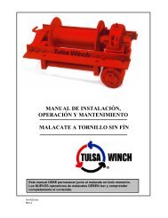
DRUM GROUP<br />
Design Revision 'B' - Effective from Serial # 46684<br />
G1146<br />
502<br />
513<br />
321 323 320<br />
310 503 313<br />
411<br />
511<br />
507<br />
421<br />
NOTE: Items 511 and 520 used only<br />
in winches with - 5 drum.<br />
505<br />
413<br />
520<br />
311<br />
410<br />
101<br />
423<br />
100<br />
420<br />
555<br />
344<br />
553<br />
556<br />
109<br />
300<br />
340 402<br />
341<br />
500<br />
515<br />
400<br />
Group drawings may reference more parts than are actually<br />
present in a specific assembly. Parts that are referenced on the<br />
drawing but are not on the PARTS LIST should be ignored.<br />
Refer to PAGE 21 for ASSEMBLY DRAWING and PAGE 25 for<br />
winch seal kit.<br />
315 PAGE 23
BRAKE GROUP<br />
Design Revision Effective from Serial # 76061<br />
G2339<br />
724<br />
712 716<br />
759<br />
754<br />
757 708 709 831 830<br />
840<br />
702<br />
720<br />
931<br />
722<br />
933<br />
737<br />
950<br />
704<br />
937<br />
710<br />
935<br />
719<br />
955<br />
440<br />
711<br />
739<br />
736<br />
723<br />
727<br />
700 701 713 750 751 752 753 707 800 811<br />
888<br />
831<br />
Group drawings may reference more parts than are actually present in a specific<br />
assembly. Parts that are referenced on the drawing but are not on the PARTS<br />
REFERENCE list should be ignored.<br />
Refer to PAGE 21 for ASSEMBLY DRAWING and PAGE 25 for winch seal kit.<br />
PAGE 24<br />
315 REV.081208
PARTS REFERENCE - BRAKE GROUP<br />
ITEM NO. QTY. PART NO. ** DESCRIPTION<br />
440 1 **** SUNGEAR<br />
700 1 * BRAKE HOUSING (INCLUDES ITEMS 701 AND 702)<br />
701 106 25270 LOOSE ROLLER 5/32 X 1.25 TOR. #E151-Q (INCLUDED IN ITEM 700)<br />
702 1 20717 NEEDLE RETAINER (INCLUDED IN ITEM 700)<br />
704 1 20712 PLANET HUB STOPPER<br />
707 1 25275 O-RING -048 4 3/4" ID 1/16" CS<br />
708 1 * CHECK VALVE<br />
709 1 * PLASTIC CAPLUG 1/8 NPT<br />
710 1 20714 BACK UP WASHER FOR OIL SEAL #25278<br />
711 1 25278 *** OIL SEAL<br />
712 1 20107 BRAKE SPACER<br />
* These parts vary.<br />
713 4 25024 DIVIDER PLATE<br />
Refer to BRAKE CODE CHART.<br />
716 3 20034 FRICTION PLATE<br />
** Effective Serial # 46684.<br />
719 1 25492 CIRCLIP ROTOR CLIP SH-106 *** Do not substitute.<br />
720 1 22881 BRAKE HUB<br />
Available from PULLMASTER<br />
722 1 20183 SPRAG CLUTCH ALIGNER<br />
or Authorized Dealer only.<br />
723 1 25187 SPRAG CLUTCH<br />
**** Refer to APPENDIX B.<br />
724 1 20183 SPRAG CLUTCH ALIGNER<br />
727 1 25492 CIRCLIP ROTOR CLIP SH-106<br />
736 1 26310 THRUST WASHER TORRINGTON # TRA 1828<br />
737 2 25483 THRUST WASHER INA # AS 3047<br />
739 1 25537 THRUST BEARING INA # AXK 3047<br />
750 1 * PISTON ASSEMBLY (INCLUDES ITEMS: 754, 757 AND 759)<br />
751 1 25528 O-RING -245 4 3/8" ID 1/8" CS, 90 DURO<br />
752 6 20340 BRAKE SPRING<br />
753 1 25261 O-RING -246 4 1/2" ID 1/8" CS, 90 DURO<br />
754 1 20732 ORIFICE PLUG<br />
757 1 25040 PIPE PLUG 1/8 - 27 NPT<br />
759 1 * STEEL BALL 5/32 DIA<br />
800 1 21079 MOTOR ADAPTOR<br />
811 1 25016 O-RING -042 3 1/4" ID 1/16" CS<br />
830 1 20519 CONNECTING TUBE<br />
831 3 25018 O-RING -010 1/4" ID 1/16" CS<br />
840 1 20870 SAFETY VALVE<br />
888 1 22962 MOTOR PLUG<br />
931 4 25264 CAPSCREW - HEX HEAD 3/8 - 16 NC X 1.00 GRADE 5<br />
933 4 25037 LOCKWASHER 3/8"<br />
935 2 25264 CAPSCREW - HEX HEAD 3/8 - 16 NC X 1.00 GRADE 5<br />
937 2 25037 LOCKWASHER 3/8"<br />
950 1 26889 *** MOTOR<br />
955 2 25536 PLASTIC CAPLUG 1.0625" -12 THREADED<br />
23111 WINCH SEAL KIT, CONSISTS OF ITEMS:<br />
505, 515, 707, 710, 711, 751, 753, 811 AND 831.<br />
BRAKE CODE CHART<br />
BRAKE CODE<br />
-12 -13 -14 -15<br />
ITEM<br />
NO.<br />
PART DESCRIPTION<br />
PART NUMBERS<br />
708 CHECK VALVE N/A 21530 21530 N/A<br />
709 1/8 NPT CAPLUG N/A 25374 25374 N/A<br />
750 PISTON ASSEMBLY 21571 21531 21531 21571<br />
759 5/32 DIA STEEL BALL N/A 25533 25533 N/A<br />
REDUCTION RATIO<br />
700 BRAKE HOUSING STANDARD 22464 22467 22467 22464<br />
700 BRAKE HOUSING 'A' 22469 22470 22470 22469<br />
315 REV.081208<br />
PAGE 25
APPENDIX A<br />
DRUM<br />
CODE<br />
CABLE DRUM SIZES<br />
INCHES<br />
(MILLIMETERS)<br />
WIRE ROPE STORAGE<br />
FEET<br />
(METERS)<br />
LINE PULL<br />
AT MAXIMUM<br />
PRESSURE*<br />
POUNDS<br />
(KILONEWTONS)<br />
LINE SPEED<br />
AT MAXIMUM<br />
VOLUME*<br />
FEET/MINUTE<br />
(METERS/MINUTE)<br />
BARE FULL BARE FULL<br />
BARREL FLANGE LENGTH 3/8 INCH 5/16 INCH 1/4 INCH DRUM DRUM DRUM DRUM<br />
LUBRICATING<br />
OIL<br />
VOLUME<br />
REQUIRED<br />
U.S.<br />
GALLONS<br />
(LITERS)<br />
STANDARD REDUCTION RATIO<br />
-1 6.13 9.0 5.25 84 122 172 2204 1633 83 111 .13<br />
(156) (229) (133) (25) (37) (52) (9.8) (7.3) (25) (34) (.5)<br />
-5 6.13 9.0 10.81 172 251 354 2204 1633 83 111 .27<br />
(156) (229) (275) (53) (76) (108) (9.8) (7.3) (25) (34) (1.0)<br />
'A' REDUCTION RATIO<br />
-1 6.13 9.0 5.25 84 122 172 1285 952 142 189 .13<br />
(156) (229) (133) (25) (37) (52) (5.7) (4.2) (43) (58) (.5)<br />
-5 6.13 9.0 10.81 172 251 354 1285 952 142 189 .27<br />
(156) (229) (275) (53) (76) (108) (5.7) (4.2) (43) (58) (1.0)<br />
* Performance specifications are based on standard hydraulic motor with 1/4 inch diameter wire rope.<br />
PAGE 26<br />
315 REV.061026
APPENDIX B<br />
ITEM NUMBERS<br />
400 420 440 500 502 511 520 556<br />
PART DESCRIPTION<br />
PLANET<br />
HUB<br />
PRIMARY<br />
PLANET<br />
GEAR<br />
SUNGEAR<br />
CABLE<br />
DRUM<br />
CABLE<br />
ANCHOR<br />
SET<br />
SCREW<br />
COUPLING<br />
TIE BAR<br />
DRUM<br />
CODE<br />
STANDARD REDUCTION RATIO<br />
PART NUMBERS<br />
-1 20705 20707 22896 21830 21882 - - 20706<br />
-5 20705 20707 22896 22227 - 25526 21620 21621<br />
DRUM<br />
CODE<br />
'A' REDUCTION RATIO<br />
PART NUMBERS<br />
-1 20912 20911 22912 21830 21882 - - 20706<br />
-5 20912 20911 22912 22227 - 25526 21620 21621<br />
315 REV.990607<br />
PAGE 27
BOLT TORQUE CHART<br />
BOLT DIAMETER<br />
Inches<br />
TORQUE<br />
Lb-Ft<br />
TORQUE<br />
Nm<br />
1/4 9 12<br />
5/16 18 24<br />
3/8 32 43<br />
7/16 50 68<br />
1/2 75 102<br />
9/16 110 149<br />
5/8 150 203<br />
3/4 265 359<br />
7/8 420 569<br />
1 640 868<br />
1 1/8 800 1085<br />
1 1/4 1000 1356<br />
NOTE:<br />
Unless otherwise specified, torque bolts per above chart.<br />
PAGE 28<br />
315 REV.990607
The Three Basic<br />
Types of<br />
PULLMASTER<br />
Planetary<br />
Winches<br />
RAPID<br />
REVERSE<br />
H and HL Series<br />
For winch operations where a<br />
load has to be lowered at high<br />
speed and with complete control<br />
the PULLMASTER planetary<br />
winches in the 'H' series offer<br />
reversing speeds approximately<br />
4.5 times faster than forward<br />
speed. <strong>Model</strong>s in the series are available in line pull<br />
capacities from 8,500 lb (3,856 kp) to 50,000 lb<br />
(22,680 kp).<br />
RECOVERY<br />
R Series<br />
The 'R' Series PULLMASTER recovery winches<br />
are of the same design concept as PULLMASTER<br />
hoisting winches. Freespooling is a standard feature<br />
of this model and is offered with a manually<br />
actuated clutch or is suitable for<br />
hydraulic remote control.<br />
EQUAL SPEED IN<br />
BOTH DIRECTIONS<br />
PL and M Series<br />
Seven basic models provide for line<br />
pull capacities from 1,102 lb (500 kp)<br />
to 50,000 lb (22,680 kp). With the<br />
available options PULLMASTER<br />
planetary winches can be adapted<br />
for a wide range of applications<br />
and for special operational<br />
requirements.<br />
<strong>Service</strong> for PULLMASTER planetary winches can be obtained through a world wide network of<br />
PULLMASTER distributors. For the distributor nearest to you contact the factory.<br />
Use only authentic PULLMASTER replacement parts in the repair of a PULLMASTER Planetary winch.<br />
Purchased items such as bearings, seals, O-rings, etc., can be supplied from the factory.<br />
However, a cross reference list for such parts is shown in the PARTS REFERENCE of this manual.<br />
When in doubt about proper function, installation or repair of a PULLMASTER planetary winch please<br />
contact your nearest PULLMASTER Distributor or the factory.