Autodesk® Inventor Autodesk® InventorTM
Autodesk® Inventor Autodesk® InventorTM
Autodesk® Inventor Autodesk® InventorTM

Create successful ePaper yourself
Turn your PDF publications into a flip-book with our unique Google optimized e-Paper software.
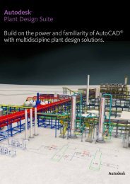
Shorten the road<br />
to done.<br />
<strong>Autodesk®</strong><br />
<strong>Inventor</strong>TM<br />
<strong>Autodesk®</strong><br />
<strong>Inventor</strong><br />
Professional 2009<br />
Routed Systems
Experience your design before it’s built.<br />
Autodesk ® <strong>Inventor</strong> software provides a comprehensive set<br />
of design tools for producing, validating, and documenting<br />
complete digital prototypes—helping manufacturers get<br />
to market faster with fewer physical prototypes and more<br />
innovative products.<br />
Contents<br />
Dynamic Simulation................................... 4<br />
Stress Analysis ............................................ 6<br />
Tube and Pipe Design ................................ 8<br />
Cable and Harness Design ..................... 10<br />
AutoCAD Integration .............................. 12<br />
Part Design ................................................ 14<br />
Sheet Metal Part Design.......................... 16<br />
Assembly Design ...................................... 18<br />
Design and Manufacturing<br />
Documentation.......................................... 21<br />
Data Management<br />
and Communication ................................ 23<br />
Customization and Automation............ 26<br />
Learning Resources................................... 27<br />
Learn More ................................................. 28<br />
The Autodesk <strong>Inventor</strong> product family is redefining<br />
traditional CAD workflows by helping engineers<br />
focus on the functional requirements of a design<br />
to drive the creation of complex 3d geometry.<br />
Reducing the time spent on geometry allows<br />
engineers to spend more time innovating designs.<br />
By rapidly building digital prototypes that validate<br />
a design’s function, engineers can catch errors<br />
before they reach production. With creative<br />
approaches to accelerate and simplify the conceptto-manufacturing<br />
process, <strong>Inventor</strong> has outsold all<br />
competitors for the seventh consecutive year.<br />
The Right Tools for Your Design Process<br />
<strong>Inventor</strong> helps designers to realize the benefits of<br />
Digital Prototyping by giving them the freedom<br />
to reuse their existing DWG designs in a 3d<br />
design environment. <strong>Inventor</strong> lets users read and<br />
write native DWG files without risking inaccurate<br />
translations, and leverage valuable DWG data<br />
to build accurate 3d part models the first time.<br />
<strong>Inventor</strong> includes tools to easily create and<br />
document 3d designs, and provides unparalleled<br />
interoperability with competitive manufacturing<br />
applications—simplifying collaboration with other<br />
companies.
Specialized Tools for Your Design Needs<br />
The Autodesk <strong>Inventor</strong> product line provides a<br />
comprehensive and integrated set of design tools<br />
for producing and documenting complete digital<br />
prototypes that validate the form, fit, and function<br />
of a design. The <strong>Inventor</strong> model is an accurate 3d<br />
digital prototype that enables users to check design<br />
and engineering data as they work, minimize the<br />
need for physical prototypes, and reduce costly<br />
engineering changes discovered after the design has<br />
been sent to manufacturing.<br />
Autodesk <strong>Inventor</strong> software products combine an<br />
intuitive 3d design environment for creating parts<br />
and assemblies with functional design tools that<br />
enable engineers to focus on a design’s function<br />
to drive the automatic creation of intelligent<br />
components such as steel frames, rotating<br />
machinery, tube and pipe runs, and electrical cable<br />
and wire harnesses.<br />
Validating the operating characteristics of designs<br />
before they are built usually requires hiring<br />
expensive consultants. The <strong>Inventor</strong> product line<br />
includes easy-to-use and tightly integrated motion<br />
simulation and stress analysis functionality, making<br />
it possible for any engineer to optimize and validate<br />
the digital prototype to predict how the design<br />
will work under real-world conditions, before the<br />
product or part is ever built.<br />
<strong>Inventor</strong> is tightly integrated with Autodesk<br />
data management applications, enabling the<br />
efficient and secure exchange of design data and<br />
promoting earlier collaboration between design and<br />
manufacturing workgroups. Different workgroups<br />
can manage and track all components of a digital<br />
prototype with the free* Autodesk ® Design Review<br />
software—the all-digital way to review, measure,<br />
mark up, and track changes to designs—allowing<br />
for better reuse of crucial design data, management<br />
of bills of materials (BOMs), and collaboration with<br />
other teams and partners.<br />
With different product configurations that offer<br />
specific levels of functionality, no company is<br />
more focused than Autodesk on helping designers<br />
create accurate digital prototypes and bring better<br />
products to market faster at less cost.<br />
Generating manufacturing documentation from a<br />
validated 3d digital prototype helps reduce errors<br />
and associated ECOs (engineering change orders)<br />
before manufacturing. <strong>Inventor</strong> offers rapid and accurate<br />
output of production-ready drawings directly<br />
from the 3d model. <strong>Inventor</strong> product bundles also<br />
include AutoCAD ® Mechanical software for situations<br />
that require a high-productivity 2d mechanical<br />
drafting tool.
Dynamic Simulation<br />
With <strong>Inventor</strong> Professional, designers can use Dynamic<br />
Simulation to predict how a product will work under realworld<br />
conditions, without having to build costly, timeconsuming<br />
physical prototypes or waiting for results from<br />
expensive consultants.<br />
Simply add the<br />
driving loads, friction<br />
characteristics, and<br />
dynamic components.<br />
Then, run the simulation<br />
to validate the design.<br />
Smooth integration with<br />
stress analysis validates<br />
component design with<br />
actual load information,<br />
rather than estimates.<br />
Simulation<br />
Simulate the operation of mechanisms and motorized<br />
assemblies to make sure designs will work,<br />
while reducing physical prototyping costs. Compute<br />
the dynamic operating conditions of the design<br />
throughout its full operating cycle, and accurately<br />
size motors and actuators to sustain actual operating<br />
loads. Analyze positions, velocities, accelerations,<br />
and loads encountered by a selected component in<br />
the mechanism.<br />
Output to Finite Element Analysis<br />
Transfer reaction forces from discrete time steps<br />
to Autodesk <strong>Inventor</strong> Stress Analysis or ANSYS ®<br />
Workbench to predict stress and deflection with accurate<br />
peak loads. Size components, such as pins and<br />
linkages, to minimize weight and material costs.
Constraint Translation<br />
Quickly and easily set up dynamic simulations to<br />
represent the operating conditions of the design.<br />
The constraint reduction engine analyzes assembly<br />
constraints to identify the relevant rigid bodies and<br />
generate the correct motion joints for simulation.<br />
Users can also apply standard geometric constraints<br />
using the included library of motion joints. Then<br />
add springs and dampers to define the coefficient of<br />
friction that applies to each joint.<br />
Load Definition<br />
Apply different driving loads and torques as well as<br />
time-based force functions using the load profile<br />
editor. Use this tool to investigate the design’s performance<br />
under a range of different load conditions.<br />
Point Trace<br />
Determine accurate component position to help<br />
provide sufficient clearance between mechanisms<br />
and fixed structures. Select any point in the model<br />
and use the Trace option to display the selected<br />
point’s location at each step in the simulation. Save<br />
simulation output, including path trace and assembly<br />
position, for use in part and assembly design.<br />
Graphing<br />
Use the comprehensive graphing capability to<br />
quickly investigate how the dynamic characteristics<br />
of the design vary through the machine’s operating<br />
cycle. Plot physical parameters—such as position,<br />
force, and acceleration—versus time. Compare<br />
different properties at each point in the simulation<br />
cycle using multiple plots on the same graph.<br />
Visualization<br />
Fully interpret the behavior and performance of<br />
your design. Animated 3d visualization shows dynamic<br />
motion based on underlying physics models<br />
and the applied load conditions.<br />
Microsoft Excel Output<br />
Export XY plot data to Microsoft ® Excel ® worksheets<br />
to analyze simulations and incorporate<br />
results in presentations and reports.
Stress Analysis<br />
The stress analysis functionality in <strong>Inventor</strong> Professional<br />
helps users understand how parts perform under load, so<br />
they know their designs have sufficient strength to perform<br />
without failure.<br />
The stress analysis tools<br />
are fully integrated with<br />
the dynamic simulation<br />
tools, enabling users to<br />
perform stress analysis<br />
with accurate load conditions<br />
that are calculated<br />
directly from the dynamic<br />
behavior of the design.<br />
Easy-to-Use, Integrated Analysis<br />
Make design decisions based on analysis results,<br />
not intuition. Integrated finite element analysis<br />
removes the need for translation of the CAD model,<br />
making it easier to use than stand-alone analysis<br />
packages. Users can examine deformation as well as<br />
maximum and minimum stresses to design higherquality<br />
parts and make sure their designs meet<br />
required safety factors.<br />
Integrated with Dynamic Simulation<br />
Analyze the stress in a moving part at different<br />
points in the mechanism’s operating cycle. Import<br />
loads from multiple steps in a dynamic simulation,<br />
and then calculate and view the resulting stresses in<br />
a single analysis run.
Model Simplification<br />
Reduce the time required to generate results from<br />
stress analysis by simplifying part geometry to<br />
suppress features during finite element analysis.<br />
Export Analysis Data to ANSYS<br />
Perform advanced studies without unnecessary and<br />
costly data translation. <strong>Inventor</strong> analysis definitions<br />
can be exported to ANSYS for use with additional<br />
validation tools.<br />
Share Validation Results<br />
Quickly and easily add analysis results to reports by<br />
exporting to an AVI or graphics file.<br />
Thin Element Solver<br />
Identify areas of high stress in thin metal parts,<br />
including those made of sheet metal, to help ensure<br />
that they can support the operating loads.
Tube and Pipe Design<br />
<strong>Inventor</strong> Professional enables users to reduce the time<br />
required to design tubing, piping, and flexible hose.<br />
The rules-based routing<br />
tools in <strong>Inventor</strong><br />
Professional select the<br />
appropriate fittings and<br />
help enable pipe runs<br />
to comply with design<br />
rules for minimum and<br />
maximum length, roundoff<br />
increments, and bend<br />
radius.<br />
Functional Route Design<br />
Simplify the design of pipe runs—or spools—to fit in<br />
complex assemblies or tight spaces. Automatically<br />
routed segments respect predefined routing styles<br />
to present users with alternative pipe routes that<br />
comply with routing rules such as minimum or maximum<br />
length criteria and bend radius. Alternatively,<br />
pipe runs can be defined manually by creating 3d<br />
sketch geometry or built up interactively using the<br />
route edit tools. Automatically routed segments<br />
can be combined with user-defined segments for<br />
maximum control.<br />
Fittings Library<br />
Improve quality, easily organize parts, and eliminate<br />
tedious searching with automatic placement of<br />
the correct part from an extensive library of piping<br />
components. The library includes commonly used,<br />
industry-standard (ANSI, DIN, ISO, and JIS) fittings,<br />
tubing, piping, and hose. Add or modify properties,<br />
including part numbers to existing parts, and<br />
control file names used to instance fittings, pipes,<br />
tubes, and other content.<br />
Flexible Hose<br />
Make sure flexible hose and fittings fit properly<br />
using a 3d digital prototype that drives accurate<br />
manufacturing documentation. The system inserts<br />
appropriate hose fittings from the Content Center<br />
and checks for minimum bend radius based on the<br />
selected hose style. Hose lengths are updated automatically<br />
for use in length roll-up commands.
Rigid Tube Routing<br />
Quickly create rigid tubes with superior control over<br />
the shape, bend angles, and radii. Create rigid tubes<br />
with an arbitrary number of bends and variable<br />
custom bend angles and radii. The radius and rotation<br />
handles offer greater control over the shape of<br />
rigid tubes.<br />
Tube and Pipe Styles<br />
Increase the quality and manufacturability of<br />
designs by helping to ensure that tube and pipe runs<br />
automatically adhere to preset design standards.<br />
Create tube and pipe styles to support the use of<br />
threaded, welded, and flanged connections. Styles<br />
define the fittings to be used for both automatic and<br />
manual routing, and enforce design rules, including<br />
minimum segment lengths and minimum bend radii,<br />
as well as the maximum length between couplings.<br />
Hygienic Pipe Runs<br />
Design process lines that comply with sterility and<br />
hygiene standards required for process equipment<br />
in the pharmaceutical, food, and personal care industries.<br />
Incorporate the correct slope into the pipe<br />
route, including use of drainable angle fittings that<br />
comply with the American Society of Mechanical<br />
Engineers (ASME) bioprocessing equipment where<br />
needed.<br />
Creating Runs<br />
Automatically populate piping routes with real<br />
parts that adhere to manufacturing standards. The<br />
Populate Route tool turns tube, pipe, and hose<br />
routes into physical pipe runs, automatically placing<br />
fittings, pipe segments, rigid tubes, and hoses as<br />
needed. Standard <strong>Inventor</strong> parts are created during<br />
this process to make it easy to perform mass<br />
property calculations and interference checks. In<br />
addition, couplings are automatically placed when<br />
pipes reach their maximum length, and users can<br />
specify length cutoff increments.<br />
Tube and Pipe Documentation<br />
Create manufacturing deliverables without redrawing—reducing<br />
errors and associated costs. Fully<br />
associative documentation for tube and pipe runs<br />
provides assembly drawings that update whenever<br />
a change is made to the 3d design. ISOGEN PCF<br />
file output creates isometric piping drawings in<br />
third-party ISOGEN software such as Alias ISOGEN,<br />
and tubing bend tables in ASCII format provide the<br />
information required by tube bending machines.
Cable and Harness Design<br />
<strong>Inventor</strong> Professional streamlines cable and harness design<br />
by using wire list information imported from schematic<br />
design packages, including AutoCAD Electrical software.<br />
®<br />
Complex electrical<br />
systems are present in<br />
almost every product<br />
or machine, and require<br />
increasingly careful<br />
design of the physical<br />
cables and harnesses.<br />
Incorporating cable and<br />
harness runs—including<br />
ribbon cables—into the<br />
digital prototype saves<br />
users time and money<br />
by calculating accurate<br />
path lengths, avoiding<br />
small radius bends, and<br />
making sure the electrical<br />
components fit into the<br />
mechanical assembly.<br />
Functional Harness Design<br />
Design cable and harness components in 3d to<br />
reduce manufacturing problems, facilitate output<br />
of manufacturing drawings, and avoid late-stage<br />
engineering change orders. In <strong>Inventor</strong>, wire list<br />
and connector information is used to drive harness<br />
design with built-in cross-checking of electrical and<br />
mechanical data so users can make sure that all<br />
wires and connectors in the wire list are represented<br />
in the 3d cable design.<br />
Wire List Input<br />
Maintain electrical design intent and reduce errors<br />
when importing wire lists into the assembly. Quickly<br />
import large wire lists from AutoCAD Electrical or<br />
third-party schematic design applications with detection<br />
and correction of missing connectors, pins,<br />
and wire definitions.<br />
Wire Routing<br />
Quickly route thousands of wires while providing<br />
control over the paths of crucial wires. Manual routing<br />
requires explicit selection of the wire’s path, interactive<br />
routing requires selection of the start/end<br />
points and the algorithm chooses the shortest path,<br />
and in automatic routing the system find the shortest<br />
possible path based on all available paths.<br />
Harness Path Definition<br />
Optimize the design of cable and harness assemblies<br />
to help ensure proper spacing for manufacturing<br />
and reduce errors in manufacturing caused by<br />
incomplete product definition. Define harness and<br />
cable paths using a point-and-click methodology<br />
that creates 3d virtual conduits (segments) in the<br />
model. Create associative relationships that help<br />
ensure that the harness updates when design components<br />
change. Add points or move existing points<br />
to refine the overall shape of the harness.<br />
10
Ribbon Cables<br />
Reduce errors in the design of electronic equipment<br />
by incorporating ribbon cables in the 3d digital prototype.<br />
Add ribbon cables between connectors with full<br />
control over the locations of twists and folds.<br />
Harness Validation<br />
Improve cable quality and manufacturability, and prevent<br />
costly recalls and product failures by adhering to<br />
design standards. <strong>Inventor</strong> automatically calculates<br />
quality parameters, including bundle diameter, bend<br />
radius, and wire lengths, whenever changes are made<br />
to the harness. As a result, users can eliminate the<br />
time-consuming and error-prone process of manually<br />
measuring a hardware prototype.<br />
Harness Documentation<br />
Quickly and easily create manufacturing documentation<br />
before building the first article. Since<br />
cable and harness geometry is native to <strong>Inventor</strong>,<br />
users can create assembly documentation showing<br />
accurate details of cable and harness placement.<br />
Comprehensive tools for the rapid generation of<br />
harness documentation include the following:<br />
Connector Authoring<br />
Set up company-specific connector libraries to<br />
encourage the use of preferred connectors in the<br />
design of electrical products. <strong>Inventor</strong> includes an<br />
extensive library of connectors to simplify selection<br />
and placement. The Content Center provides an<br />
easy-to-use editor to add user-defined connectors,<br />
as well as add or modify properties such as part<br />
numbers and default file names used when instancing<br />
connectors.<br />
• Automatic nailboard diagrams for 3d wire harnesses,<br />
cables, and ribbon cables that update<br />
automatically as the 3d design changes<br />
• Reports including wire run lists, termination<br />
charts, cut tables, and other reports needed for<br />
the design and manufacture of the harness<br />
• XML output files for transferring the final wire connectivity<br />
information to streamline the creation of<br />
schematics and wiring diagrams using AutoCAD<br />
Electrical or other schematic design software<br />
11
AutoCAD Integration<br />
<strong>Inventor</strong> makes it easy for users of AutoCAD software to<br />
®<br />
realize the benefits of Digital Prototyping by leveraging<br />
investments in AutoCAD expertise and DWG design data.<br />
<strong>Inventor</strong> delivers the<br />
industry’s leading<br />
integration of 2d and<br />
3d design, providing<br />
direct read and write<br />
of native DWG files,<br />
while maintaining full<br />
associativity to the 3d<br />
model—without the need<br />
for data-compromising<br />
translators.<br />
With <strong>Inventor</strong>, reuse<br />
valuable data with<br />
rapid access to existing<br />
2d information. And,<br />
because users can save<br />
drawings as DWG files,<br />
they can easily share<br />
insights gained from the<br />
digital prototype with<br />
partners and suppliers<br />
who rely on AutoCAD<br />
software. Views<br />
generated from 3d part<br />
and assembly designs,<br />
such as schematics and<br />
plant layouts, can also be<br />
combined with AutoCAD<br />
data. Users can then<br />
update 2d drawings by<br />
inserting a view of new<br />
3d designs—reducing the<br />
cost of upgrading existing<br />
equipment.<br />
Template Synchronization<br />
Open a DWG file in <strong>Inventor</strong> and automatically<br />
create layers and dimension and text styles based<br />
on the AutoCAD styles in the DWG file, thus<br />
reducing the time required to create drawings that<br />
comply with customers’ drawing standards.<br />
Ease of Use<br />
Reduce the time and training required for AutoCAD<br />
users to become proficient in 3d design workflows.<br />
Simplify the transition from AutoCAD software<br />
to <strong>Inventor</strong> in a familiar design environment with<br />
recognizable icons, AutoCAD-compatible shortcuts,<br />
cursor-based prompts, and command redo. User<br />
profiles enable users to configure <strong>Inventor</strong> to match<br />
the way they work, with out-of-the-box profiles<br />
for AutoCAD and <strong>Inventor</strong> experts. In addition,<br />
users can transfer their settings between different<br />
computers by exporting the profile to XML.<br />
12
DWG Save<br />
Integrate DWG technology into the 3d design<br />
workflow to take advantage of existing skills; easily<br />
combine part, assembly, and schematic drawings<br />
data; and streamline communication with suppliers<br />
and partners who rely on DWG technology. This<br />
feature stores <strong>Inventor</strong> drawing views in the DWG<br />
file to provide view, plot, and measure capabilities<br />
in AutoCAD with complete visual fidelity, while<br />
preserving fully associative drawing updates.<br />
AutoCAD Blocks from <strong>Inventor</strong> Views<br />
Reduce the cost of using 3d for upgrade projects<br />
originally designed in 2d. This feature generates<br />
AutoCAD blocks from <strong>Inventor</strong> drawing views so<br />
users can redesign subassemblies using <strong>Inventor</strong><br />
and then integrate the new drawing views directly<br />
into the original drawings.<br />
Direct DWG Open<br />
Gain access to existing 2d design data without<br />
installing or learning AutoCAD software. Open<br />
AutoCAD drawings directly in the <strong>Inventor</strong> application<br />
to view, plot, and measure using familiar<br />
<strong>Inventor</strong> commands. Incorporate existing 2d design<br />
data into 3d design workflows using Copy and Paste<br />
commands.<br />
<strong>Inventor</strong> and AutoCAD Mechanical<br />
Interoperability<br />
Accelerate time to market and reduce errors by<br />
enabling associative 2d and 3d collaboration.<br />
With this interoperability, AutoCAD Mechanical<br />
software creates drawings of <strong>Inventor</strong> components<br />
by enabling users to open native <strong>Inventor</strong> parts and<br />
assemblies. When the design changes in <strong>Inventor</strong>,<br />
the AutoCAD Mechanical drawing is automatically<br />
updated.<br />
13
Part Design<br />
<strong>Inventor</strong> software helps designers reach the next level of<br />
efficiency by making it easier to reuse design data, convey<br />
design intent, and work with fully associative models to<br />
make sure any changes to the part design are reflected in the<br />
assembly model and drawing files.<br />
Improve productivity by<br />
automating repetitive<br />
design workflows for<br />
frequently used custom<br />
features and parts. Using<br />
the iPart technology in<br />
<strong>Inventor</strong>, companies can<br />
easily set up libraries of<br />
intelligent parts to make<br />
sure that frequently used<br />
parts are created the same<br />
way every time.<br />
Sketching<br />
Evaluate different design ideas before creating<br />
detailed part and assembly models. By using the<br />
<strong>Inventor</strong> sketch environment, designers can quickly<br />
capture design ideas as versatile 2d layouts. By<br />
combining the power of constraints with easy-touse<br />
tools for modifying sketches, designers can try<br />
different design concepts and control color and line<br />
style to help convey design ideas.<br />
14
Advanced Shape Description<br />
Create a wide range of complex geometries by easily<br />
combining solids and surfaces. <strong>Inventor</strong> gives users<br />
precise control of shape characteristics, such as<br />
tangency and continuity. Advanced modeling tools<br />
include Loft to a Point, N-Sided Patch, Sweep Normal<br />
to Surface, Area Loft, Centerline Loft, G2 Continuous<br />
Fillets, Full Round Fillets, and Face-to-Face Fillets.<br />
Import from AliasStudio<br />
Use concept design data from Autodesk ®<br />
AliasStudio software to reduce the time required<br />
to complete 3d product design. Incorporate curve<br />
and surface data from AliasStudio into <strong>Inventor</strong> part<br />
models using DWG import and export tools built<br />
into the two products.<br />
Sculpt Tool<br />
Quickly and easily modify shape details using<br />
surfaces from <strong>Inventor</strong> or by incorporating imported<br />
surfaces. Construct 3d part geometry from closed<br />
set surfaces, and incorporate imported surface<br />
data into the model using the Sculpt tool to modify<br />
existing parts by adding or removing material.<br />
Image courtesy of ADEPT Airmotive<br />
Surface Quality Analysis<br />
Create models with high-quality surface characteristics,<br />
and check design data for manufacturability<br />
to avoid costly changes during manufacturing setup.<br />
Zebra and Gaussian analysis tools simplify the<br />
process of checking for tangency, continuity, and<br />
curvature.<br />
Draft Angle and Cross Section Analysis<br />
Cross section analysis displays wall thickness, colorcoded<br />
feedback of minimum and maximum thickness<br />
violations, and moment of inertia at the end of the<br />
cross section. Draft angle analysis displays colorcoded<br />
draft angle based on a pull direction, which<br />
can be defined by an axis, plane, or planar face.<br />
15
Sheet Metal Part Design<br />
Autodesk <strong>Inventor</strong> helps users simplify the design<br />
of complex sheet metal parts.<br />
<strong>Inventor</strong> improves<br />
productivity during the<br />
design of sheet metal<br />
parts by providing a<br />
digital prototype that<br />
combines manufacturing<br />
information (such as<br />
punch tool parameters<br />
and custom bend tables)<br />
with an accurate 3d<br />
model of sheet metal<br />
folding and a flat pattern<br />
editing environment<br />
where manufacturing<br />
engineers can tweak<br />
flat patterns to optimize<br />
manufacturing costs.<br />
Sheet Metal Flanges<br />
Quickly design sheet metal parts in 3d that<br />
accommodate specific manufacturing processes and<br />
shop capabilities. Edge chaining allows creation of<br />
multiple flanges in a single stop, while rich unfold<br />
options and automatic mitering reduce the time<br />
required to define the folded part model.<br />
Sheet Metal Styles<br />
Generate flat patterns that accurately reflect your<br />
manufacturing capabilities. Sheet metal unfolding<br />
is controlled through styles that define the material<br />
thickness, bend rules, and corner reliefs. Both linear<br />
unfolding and custom bend tables can be used to<br />
control the unfolding geometry.<br />
16
Flat Pattern Features<br />
Generate optimized flat patterns to eliminate<br />
unnecessary manufacturing costs. Unfold sheet<br />
metal models to create flat patterns with associative<br />
flat-pattern editing to support cleanup operations<br />
such as modifying corner reliefs to match specific<br />
capabilities available on the shop floor.<br />
Sheet Metal Fasteners<br />
Quickly insert specialized sheet metal fasteners in<br />
the sheet metal design. A comprehensive range of<br />
PEM fasteners are included in the Content Center.<br />
Punch Libraries<br />
Users can define their own sheet metal punch<br />
libraries to standardize punch usage and reduce<br />
computer numerical control (CNC) tooling costs.<br />
Table-driven punches enable users to define<br />
families of punches, typically different sizes of<br />
the same punch shape with full representation of<br />
manufacturing parameters, including PunchID,<br />
punch depth, and sketches for alternate punch<br />
representations.<br />
DXF Output<br />
Reduce programming time by eliminating time<br />
spent cleaning up DXF files for CNC machining.<br />
DXF/DWG export for sheet metal provides control<br />
of preprocessing and postprocessing options such<br />
as DXF/DWG file version, layer mapping, userdefined<br />
chord length for spline simplification, and<br />
customization through external XML files.<br />
Sheet Metal Manufacturing Drawings<br />
Quickly create accurate manufacturing drawings<br />
to support sheet metal manufacturing operations.<br />
Document flat pattern drawings by inserting punch<br />
notes, punch tables, and bend tables that display<br />
punch and bend data from the 3d mode and select<br />
display of bend directions using drawing styles.<br />
17
Assembly Design<br />
<strong>Inventor</strong> combines Design Accelerators with easy-to-use<br />
assembly tools so users can be sure that every part and<br />
component in an assembly design fits correctly.<br />
Accurately validate<br />
interference and mass<br />
properties to produce<br />
high-quality products<br />
the first time around.<br />
<strong>Inventor</strong> provides the tools<br />
to control and manage<br />
the data created by large<br />
assembly designs so users<br />
can work on just the<br />
components required to<br />
complete a particular part<br />
of the design.<br />
Assembly Design<br />
Quickly assemble individual parts and subassemblies<br />
to define the complete product structure and verify<br />
that the product can be assembled. Insert and<br />
position new components in the assembly using<br />
constraints to capture the positional relationships<br />
that define fixed and moving components.<br />
18
Interference Analysis and Contact<br />
Detection<br />
Eliminate costly errors and improve manufacturability<br />
by testing assembly function within <strong>Inventor</strong>. Check<br />
for both static interference between parts with<br />
graphic highlighting of overlapping material, and<br />
then test for potential collisions between moving<br />
parts by driving assembly constraints or dragging<br />
components until they collide.<br />
AutoLimits<br />
Reduce errors and engineering changes through<br />
automatic monitoring of crucial design parameters.<br />
Use AutoLimits to monitor length, distance, angle,<br />
diameter, loop length, area, volume, and mass.<br />
AutoLimits icons change color when the monitored<br />
parameters exceed the prescribed parameter range.<br />
Assembly Configurations<br />
Easily design and document product families using<br />
assembly configurations to define variations from<br />
a master assembly. Exclude or substitute individual<br />
components and make changes to dimension and<br />
constraint values. Then document the whole part or<br />
assembly configuration using the Table tool, which<br />
automatically creates the parameter table in a 2d<br />
drawing.<br />
Large Assembly Management<br />
Realize the benefits of 3d design when developing<br />
very large assemblies. With level of detail (LOD)<br />
representations, users have full control over how<br />
much information to load when working with<br />
large assemblies. Control memory consumption<br />
by suppressing components. A large assembly<br />
“capacity meter” provides a visual indication of how<br />
much memory is available.<br />
Design Accelerators<br />
Move beyond 2d drafting and 3d modeling to<br />
rapidly design, analyze, and generate commonly<br />
used machine components from the functional<br />
requirements and specifications such as power,<br />
speed, torque, material properties, working<br />
temperatures, and lubrication conditions. <strong>Inventor</strong><br />
software includes Design Accelerators for bolted<br />
connections, shafts, bearings, O-rings, spur gears,<br />
belt and chain drives, pins, and springs.<br />
19
Frame Generator<br />
Quickly design and develop welded frames for<br />
industrial machinery applications. The Frame<br />
Generator builds up structural frames by dropping<br />
predefined steel shapes onto wireframe or solid<br />
skeletal frames and simplifies creation of end<br />
conditions with predefined options for mitered,<br />
notched, and straight butt welded joints. It includes<br />
profile authoring so users can add custom profiles to<br />
the existing library of standard profiles.<br />
Content Center<br />
The Content Center provides fast and easy access<br />
to frequently used content, simplifying creation,<br />
reuse, and management of all standard company<br />
content. The Content Center is a centralized library<br />
for engineering content that provides an easy-to-use<br />
content browser with search and filter tools to help<br />
users quickly find the right part families. It includes<br />
more than 650,000 components—such as nuts, bolts,<br />
and screws—and enables companies to add in-house<br />
parts and standard features to user-defined libraries.<br />
Weldments<br />
Improve quality and documentation of welded<br />
assemblies. Define weld preparation, weld creation,<br />
and postweld operations with full 3d representation<br />
of fillet, gap, or groove welds that provide weldment<br />
analysis and bead volume reports. Automatically<br />
create 3d annotation based on industry or company<br />
standards, and generate associative 2d weld symbols<br />
for documentation.<br />
Supplier Content Center<br />
Reduce the time and effort required to incorporate<br />
standard components into designs. The Supplier<br />
Content Center provides web-based access to<br />
component models from more than 100 leading<br />
manufacturers. The simple-to-use browser provides<br />
quick and easy access to models in native <strong>Inventor</strong><br />
format. And it is fully integrated with the Autodesk<br />
<strong>Inventor</strong> Content Center.<br />
Design Doctor<br />
Use the Design Doctor feature to find and fix errors<br />
in 3d models. This diagnostic tool identifies potential<br />
design issues and recommends corrections.<br />
Assembly Level STL Output<br />
Quickly create source stereolithography (STL) files<br />
directly from the <strong>Inventor</strong> assembly environment for<br />
rapid prototyping of <strong>Inventor</strong> assemblies.<br />
20
Design and Manufacturing Documentation<br />
Autodesk <strong>Inventor</strong> includes comprehensive tools to generate<br />
engineering and manufacturing documentation from the<br />
digital prototype. These tools can help users reduce errors<br />
and deliver designs in less time.<br />
<strong>Inventor</strong> takes the production<br />
of manufacturing<br />
documentation to the<br />
next level of productivity<br />
through automatic generation<br />
of drawing views<br />
and tools for finishing<br />
drawings.<br />
And, with support for all<br />
major drawing standards,<br />
full associativity with the<br />
3d model (so drawings<br />
update when the design<br />
changes), and output in<br />
the DWG format, <strong>Inventor</strong><br />
is the best choice for<br />
creating and sharing DWG<br />
drawings.<br />
Automatic Drawing Views<br />
Dramatically reduce drawing creation time over<br />
traditional 2d methods. Automatic drawing views<br />
enable users to<br />
• Call out the views needed on the drawing sheet,<br />
including front, side, ISO, detail, section, and<br />
auxiliary views, and let <strong>Inventor</strong> project the geometry<br />
with comprehensive options for controlling<br />
hidden-line display at the component level<br />
• Retrieve dimension data from the 3d model to<br />
quickly place the dimensions, including isometric<br />
view dimensions, and let <strong>Inventor</strong> update the dimensions<br />
when changes are made to the 3d model<br />
• Use a comprehensive set of dimension,<br />
annotation, and 2d symbols for quick and flexible<br />
completion of the drawing set<br />
• Create overlay drawing views that illustrate<br />
various potential states of assemblies<br />
• Access support for technical drawing standards,<br />
including ANSI, BSI, DIN, ESKD, GB, ISO, and JIS<br />
21
Automatic Drawing Updates<br />
Reduce errors and the need for manual checking<br />
through automatic drawing update. <strong>Inventor</strong><br />
associates drawing views to the original<br />
components so any change made to a part or an<br />
assembly is automatically reflected in the drawing.<br />
<strong>Inventor</strong> also supports global updates of drawing<br />
resources, such as title blocks, borders, and<br />
sketched symbols.<br />
Bill of Materials<br />
Provide earlier visibility into accurate component<br />
lists to improve costing and sourcing decisions.<br />
Simplify release to manufacturing with accurate<br />
engineering BOM data. The BOM is a single source<br />
for managing the assembly and subassembly<br />
structure of purchased and nonpurchased parts,<br />
including virtual components. Timesaving features<br />
include the following:<br />
Associative Parts List<br />
Automatically generate and update accurate parts<br />
lists in a fraction of the time required by traditional<br />
2d methods, virtually eliminating human error.<br />
The associative parts list enables users to maintain<br />
an accurate parts list with part and subassembly<br />
quantities that are automatically kept up-to-date,<br />
organized, and populated into a drawing parts list.<br />
Rapidly add balloons and item numbers to assembly<br />
drawings. And users have greater flexibility in customizing<br />
parts lists to meet company standards.<br />
• Automatic numbering with support for numeric<br />
and alpha characters, and item number override<br />
• Material definition for virtual components, such<br />
as glue and paint<br />
• Direct editing of materials in the BOM table,<br />
which allows material changes to be made to more<br />
than one item at the same time<br />
Technical Illustrations<br />
Use the presentation environment in <strong>Inventor</strong><br />
to quickly create technical illustrations, process<br />
sheets, training materials, part manuals, assembly<br />
instruction sheets, and videos to train assembly<br />
teams on the manufacturing floor.<br />
22
Data Management and Communication<br />
<strong>Inventor</strong> enables the efficient and secure exchange of design<br />
data to support collaboration between different engineering<br />
contributors, including industrial design, product design, and<br />
manufacturing.<br />
This capability allows<br />
design workgroups to<br />
manage and track all<br />
the design components<br />
of a digital prototype,<br />
helping designers reuse<br />
crucial design data, manage<br />
BOMS, and promote<br />
earlier collaboration with<br />
manufacturing teams and<br />
clients.<br />
Through a comprehensive<br />
suite of native translators,<br />
<strong>Inventor</strong> provides the<br />
interoperability that enables<br />
companies to take<br />
on projects in which part<br />
of the 3d data originates<br />
from other CAD systems<br />
and satisfy customer<br />
requests for 3d models in<br />
other native formats.<br />
Autodesk Vault Integration<br />
Autodesk ® Vault data management software is a<br />
centralized application for workgroups that securely<br />
stores and manages work-in-progress design data<br />
and related documents. Use it to maximize return<br />
on your company’s investment in design data by<br />
driving design reuse.<br />
Autodesk Productstream<br />
Help ensure that your company’s designs are<br />
complete, accurate, approved, and released to<br />
manufacturing in a timely and effective manner.<br />
Autodesk ® Productstream ® software (sold<br />
separately) automates the release management<br />
process by managing engineering changes and<br />
BOMs while the engineering department maintains<br />
control of the design data.<br />
Autodesk <strong>Inventor</strong> Studio<br />
Improve communication with customers and<br />
other decision makers by creating high-quality<br />
photorealistic renderings and animations in the<br />
<strong>Inventor</strong> design environment. Autodesk ® <strong>Inventor</strong><br />
Studio software gives design engineers direct<br />
access to this specialized and typically expensive<br />
functionality. Mirror and turntable animation tools<br />
and a streamlined user interface reduce the time<br />
required to set up and create cyclic animation<br />
sequences.<br />
23
Data Management and Communication<br />
DWF Publishing<br />
Improve product quality, decrease time to market,<br />
and reduce scrap and rework costs by using<br />
DWF technology to streamline communication<br />
with suppliers, purchasing, and other supply<br />
chain partners. Publish the information required<br />
by manufacturing partners, including assembly<br />
animations and detailed step-by-step assembly<br />
instructions, 2d drawings, and 3d models with BOM<br />
information.<br />
DWF Markup<br />
Easily track, manage, and verify multiple markups<br />
and design changes throughout the design review<br />
process. Overlay DWF markups directly onto<br />
<strong>Inventor</strong> drawings, provide status, and make<br />
changes. Users can then republish or “round-trip”<br />
those changes back to the design reviewer to<br />
complete the process.<br />
Publishing Formats<br />
Share product information with partners and<br />
customers who need to incorporate your designs<br />
into their products. Publish <strong>Inventor</strong> drawings as<br />
PDF files, publish 3d part and assembly models in<br />
SAT or JT format, and create STL files for output to<br />
stereolithography and 3d print machines.<br />
24
AEC Exchange<br />
The AEC (Architecture, Engineering, and<br />
Construction) Exchange tool creates and publishes<br />
simplified 3d representations, intelligent<br />
connection points, and additional information in<br />
native file formats for AutoCAD ® MEP software.<br />
Users can also export 3d geometry to AutoCAD ®<br />
Architecture, Revit ® -based software, and AutoCAD<br />
software.<br />
STEP/IGES<br />
Simplify accurate collaboration with suppliers and<br />
customers by enabling sharing and reuse of design<br />
data with 3d CAD/CAM systems. Read and write<br />
design and drawing data using industry-standard<br />
formats.<br />
Construction Environment<br />
Reduce the time required to inspect and repair<br />
customer data files. The <strong>Inventor</strong> Construction<br />
Environment provides fault-tolerant import of large<br />
STEP and IGES data sets, with a quarantine to hold<br />
entities containing geometric problems such as surface<br />
slivers and mismatched boundary curves. The<br />
construction environment also includes a comprehensive<br />
toolkit for inspecting, editing, and correcting<br />
quarantined entities, including solids, surfaces,<br />
wireframes, and points. Data sets can be corrected<br />
and promoted into 3d part models, surfaces, or 3d<br />
wireframes.<br />
Native Translators<br />
Streamline projects that require opening files<br />
from vendors or customers in native formats.<br />
Deliver 3d design data to customers or vendors<br />
who prefer native file formats. Users can easily<br />
exchange data between Autodesk <strong>Inventor</strong>, UGS, ®<br />
SolidWorks, ® and Pro/ENGINEER ® by importing and<br />
exporting Parasolid, ® importing UG-NX, importing<br />
SolidWorks, importing and exporting Granite, and<br />
importing Pro/ENGINEER directly with <strong>Inventor</strong>.<br />
25
Customization and Automation<br />
<strong>Inventor</strong> helps users make the most of their investment in 3d<br />
by using the <strong>Inventor</strong> API (application programming interface)<br />
to streamline frequently used procedures and automate<br />
specialized workflows that support design standards and<br />
engineering processes.<br />
Increase speed and productivity<br />
with configurable<br />
styles so drawings conform<br />
to standards, and publish<br />
custom components in the<br />
Content Center to make<br />
sure that designers use<br />
appropriate components in<br />
their designs.<br />
Styles<br />
Work faster by instantly changing the formatting of<br />
an entire document, while maintaining consistency<br />
with company standards. Styles are combinations<br />
of formatting characteristics such as font, font size,<br />
color, standards, linetype, and material. They are<br />
easily named and stored as templates, and are used<br />
to control all aspects of drawing formats. When<br />
users apply a style, all the formatting instructions in<br />
that style are applied at one time, and a set of common<br />
styles can be configured for use by an entire<br />
project team.<br />
Task Scheduler<br />
Increase productivity by automating repetitive and<br />
nonproductive tasks. The <strong>Inventor</strong> Task Scheduler<br />
enables users to schedule single or multiple (batch)<br />
automated tasks including DWF publishing, printing,<br />
file migration, IGES and STEP transfers, and vault<br />
operations. Users can also check out and download<br />
files from the Vault.<br />
Content Center Publishing Tools<br />
Quickly prepare and publish intelligent part libraries.<br />
The publishing tools in the Content Center<br />
include an editing environment and batch processing<br />
of large data sets to streamline the process of<br />
preparing and publishing company parts as well as<br />
vendor catalogs.<br />
Open API<br />
Increase productivity by developing tools to automate<br />
your company’s design and documentation<br />
processes. <strong>Inventor</strong> includes a well-documented API<br />
to create customized programs to automate specialized<br />
workflows and extend the <strong>Inventor</strong> data model<br />
with custom attributes.<br />
26
Learning Resources<br />
<strong>Inventor</strong> offers a range of learning and reference resources to<br />
help users maintain skills and quickly make the most of the 3d<br />
design environment.<br />
With <strong>Inventor</strong>, users can<br />
learn new skills, look<br />
up information about<br />
procedures and tools,<br />
and get the latest tips<br />
and tricks needed to stay<br />
productive.<br />
Advanced Help System<br />
Speed the transition to 3d with contextual help. The<br />
advanced help system is easier to use with improved<br />
navigation and profiles that present users with the<br />
right information based on their user profile.<br />
Engineer’s Handbook<br />
Save time researching engineering formulas,<br />
tables, and standards. The Engineer’s Handbook<br />
provides a comprehensive online reference of<br />
engineering theory, formulas, and algorithms, and<br />
a manufacturing knowledge base that is easily<br />
accessible from anywhere in <strong>Inventor</strong>.<br />
Tutorials and Skill Builders<br />
Use extended learning modules, including tutorials<br />
with Show Me animations and Skill Builders, to<br />
enhance understanding and skills.<br />
E-Learning<br />
Accelerate learning through flexible access to<br />
tutorials and best practices. A valuable component<br />
of Autodesk ® Subscription, e-Learning provides a<br />
continually expanding curriculum of short training<br />
exercises.<br />
Deployment Guide<br />
Complete the installation of <strong>Inventor</strong> with minimum<br />
time and effort. Whether you are planning a new<br />
deployment or upgrading to Autodesk <strong>Inventor</strong><br />
2009, this easy-to-read booklet provides the<br />
information you need to succeed.<br />
27
Learn More<br />
Learn about the different <strong>Inventor</strong> products available to<br />
fit your specific design needs, and discover why <strong>Inventor</strong><br />
products are the best choice for manufacturing companies.<br />
For more information, visit www.autodesk.com/inventor.<br />
Autodesk <strong>Inventor</strong><br />
Suite 2009<br />
Autodesk <strong>Inventor</strong><br />
Routed Systems Suite 2009<br />
Autodesk <strong>Inventor</strong><br />
Simulation Suite 2009<br />
Autodesk <strong>Inventor</strong><br />
Professional 2009<br />
Autodesk <strong>Inventor</strong> • • • •<br />
AutoCAD Mechanical • • • •<br />
Cable and Harness Design • •<br />
Tube, Pipe, and Flexible<br />
Hose Design • •<br />
Stress Analysis (FEA) • •<br />
Dynamic Simulation • •<br />
Autodesk Vault • • • •<br />
28
Digital Heading Prototyping large > for KievitPro the Manufacturing Regular Market 23 on 23 pt, 75%<br />
Autodesk<br />
black. Ut<br />
is<br />
enim<br />
a world-leading<br />
ad mini<br />
supplier<br />
mim veniami<br />
of engineering<br />
quis<br />
software,<br />
nostrud<br />
providing exercitation companies ullam, with corpor tools to suscipit experience laboris their ideas Lorem<br />
before ipsum they etalus are real. siti By amet, putting duis powerful autem Digital conitu Prototyping secutur<br />
technology adipscing within elitsef the diam reach eiusmod of mainstream magnus. manufacturers, Etion<br />
Autodesk is changing the way manufacturers think about their<br />
design ullam, processes corpor and suscipit is helping laboris them Lorem create more ipsum productive etalus<br />
workflows. siti amet, The duis Autodesk autem approach conitu to secutur Digital Prototyping adipscing is<br />
unique elitsef in diam that it eiusmod is scalable, magnus. attainable, and cost-effective, which<br />
allows a broader group of manufacturers to realize the benefits<br />
with minimal disruption to existing workflows, and provides the<br />
most straightforward path to creating and maintaining a single<br />
digital model in a multidisciplinary engineering environment.<br />
Learn More or Purchase<br />
Access specialists worldwide who can provide product expertise, a deep<br />
understanding of your industry, and value that extends beyond your software<br />
purchase. To purchase Autodesk ® <strong>Inventor</strong> software contact an Autodesk<br />
Premier Solutions Provider or Autodesk Authorized Reseller. To locate the<br />
reseller nearest you, visit www.autodesk.com/reseller.<br />
Learn about the different <strong>Inventor</strong> products available to fit your specific<br />
design needs, and discover why <strong>Inventor</strong> products are the best choice for<br />
manufacturing companies. For more information, visit www.autodesk.com/<br />
inventor.<br />
Autodesk Services and Support<br />
Accelerate return on investment and optimize productivity with innovative<br />
purchase Text heading methods, > KievitPro companion Bold products, 8.5 on 10.5 consulting pt, product services, family support, color and<br />
training Body Text from > KievitPro Autodesk Regular and Autodesk 8.5 on 10.5 authorized pt, black. partners. lorem ipsum Designed etalus to sit get amet, you<br />
up duis to autem speed consecutur and keep you adipscing ahead of elit, the sef competition, diam nonumy these eiusmod tools help tempor you incident make<br />
the ut labore most of magna your aliquam software erat purchase—no volupat. Ut matter enim ad what minimim industry veniami you are quis in. To<br />
learn nostrud more, exercitation visit www.autodesk.com/servicesandsupport.<br />
ullam, corpor suscipit laboris nisi aliquip ex ea commodo<br />
conseauat. Duis autem vel eum irure etalus in reprehjenderit in volupate velit<br />
Autodesk ewsse moestai Subscription xom consequat.<br />
Get the benefits of increased productivity, predictable budgeting, and simplified<br />
license Text heading management with Autodesk Subscription. You get any new upgrades<br />
of Body your Text. Autodesk Vel illum software etalusim and eu any fugiat incremental nulla pariartur—ignissim product enhancements, qui blandit<br />
if praes these entl are upatum released delenit during aigue your duos subscription etalus et term, molestais and you excepturisio get exclusive toccaecet<br />
license cupidat terms non. Lorem available ipsum only etalus to subscription sit amet, duis members. autem A consecutur range of community adipscing elit,<br />
resources, sef diam nonumy including eiusmod web support te mpor direct incident from ut Autodesk labore magna technical aliquam experts, erat.<br />
self-paced training, and e-Learning, help extend your skills and make Autodesk<br />
Subscription Text headingthe best way to optimize your investment. To learn more, visit<br />
www.autodesk.com/subscription.<br />
Body text. Lorem ipsum etalus sit amet, duis autem consecutur adipscing elit,<br />
sef diam nonumy eiusmod tempor incident ut labore magna aliquam erat<br />
volupat. Ut enim ad minimim veniami quis nostrud exercitation ullam, corpor<br />
suscipit *Free products laboris are subject nisi ut to the aliquip terms and ex conditions ea commodo of the end-user conseauat. license agreement Duis autem that accompanies vel eum<br />
irure download etalus of the in software. reprehjenderit.<br />
Cover rendering courtesy of Prensa Jundiaí, Brazil<br />
Autodesk, AutoCAD, AliasStudio, Autodesk <strong>Inventor</strong>, Design Doctor, DWF, DWG, DXF, <strong>Inventor</strong>, Productstream,<br />
and Revit are registered trademarks or trademarks of Autodesk, Inc., in the USA and/or other countries. All other<br />
brand names, product names, or trademarks belong to their respective holders. Autodesk reserves the right to<br />
Legal alter product text > KievitPro offerings Regular and specifications 6 8 pt, black at any — time Registered without trademarks notice, and of is Autodesk, not responsible Inc., in for the typographical USA or<br />
and/or graphical other errors countries. that may All appear other in product this document. names, brand names, or trademarks belong to their respective<br />
holders. © 2008 Autodesk, © 2008 Autodesk, Inc. All rights Inc. All reserved. rights reserved. BR0A1-000000-MZ0X<br />
part number