ZERON 100 Welding Guide [Corrosion Resistant ... - Rolled Alloys
ZERON 100 Welding Guide [Corrosion Resistant ... - Rolled Alloys
ZERON 100 Welding Guide [Corrosion Resistant ... - Rolled Alloys

Create successful ePaper yourself
Turn your PDF publications into a flip-book with our unique Google optimized e-Paper software.
WELDING GUIDELINES<br />
<strong>ZERON</strong> ® <strong>100</strong><br />
UNS S32760<br />
THE GLOBAL LEADER IN SPECIALTY ALLOYS<br />
CORROSION RESISTANT ALLOYS
<strong>ZERON</strong> ® <strong>100</strong> <strong>Welding</strong> <strong>Guide</strong>lines<br />
Contents<br />
Preparation for welding <strong>ZERON</strong> <strong>100</strong> ....................................................................................................................................................2<br />
<strong>Welding</strong> Consumables........................................................................................................................................................................2<br />
Typical Joint Configurations.................................................................................................................................................................2<br />
<strong>Welding</strong>..........................................................................................................................................................................................3<br />
<strong>Welding</strong> Procedure............................................................................................................................................................................4<br />
Post Weld Cleaning...........................................................................................................................................................................6<br />
Health and Safety.............................................................................................................................................................................6<br />
Summary........................................................................................................................................................................................6<br />
<strong>ZERON</strong> ® <strong>100</strong> Super Duplex Stainless Steel<br />
<strong>ZERON</strong> <strong>100</strong>, invented and developed by RA Materials (formerly Weir Materials), was the first of the super duplex stainless steels.<br />
The unique chemical composition has been shown to be correctly balanced to offer the best combination of corrosion resistance and<br />
strength. The steel is tightly controlled from melting through manufacture to ensure a better performance than the same generic<br />
grade. <strong>ZERON</strong> <strong>100</strong> is available in all product forms, many from stock, with a proven track record through manufacture, fabrication,<br />
and successful service.<br />
When welding <strong>ZERON</strong> <strong>100</strong> super duplex stainless steel, there are several factors that must be considered. These guidelines highlight<br />
the main factors that must be taken into account. They relate particularly to welds to be used in the “as-welded” condition,<br />
made using all the common arc welding processes. The same principles apply if post weld heat treatment is being applied.<br />
The RA ® is a registered trademark of <strong>Rolled</strong> <strong>Alloys</strong><br />
<strong>ZERON</strong> ® <strong>100</strong> is a registered trademark of RA Materials<br />
STT ® (Surface Tension Transfer ® ) are registered trademarks of Lincoln Electric<br />
DSP (Dual Sync Pulse<strong>Welding</strong>)is a registered trademark of Dimetricks Inc.<br />
The data and information in this printed matter are believed to be reliable. However, this material is not intended as a substitute for competent professional engineering assistance which is a requisite to any specific application. <strong>Rolled</strong> <strong>Alloys</strong> makes no<br />
warranty and assumes no legal liability or responsibility for results to be obtained in any particular situation, and shall not be liable for any direct, indirect, special, or consequential damage therefrom. This material is subject to revision without prior notice.<br />
1
Preparation For <strong>Welding</strong> <strong>ZERON</strong> <strong>100</strong><br />
It is strongly recommended that a <strong>Welding</strong> Procedure Specification (WPS)<br />
and corresponding welding Procedure Qualification Record (PQR) be available<br />
prior to commencement of production welding. The WPS should be qualified<br />
to a higher level than the statutory requirements of the base codes such<br />
as ASME etc. and should include an ASTM G48 Method A corrosion test,<br />
a microstructural evaluation and ferrite determination in addition to the<br />
mechanical and non-destructive tests required. Welder qualification (WPQ)<br />
should also carry these extra requirements to show that the metallurgical<br />
quality of the weld area is satisfactory as well as the structural integrity for<br />
the codes. There should be considerable emphasis by the <strong>Welding</strong> Engineer<br />
on maintaining the qualified parameters throughout production welding.<br />
Handling and Storage of Parent Material<br />
All duplex stainless steels should be handled and stored under conditions<br />
which prevent contamination from other ferrous and nonferrous alloys.<br />
Stainless steel (or wood, plastic or other non-metallic material) protective<br />
covers should be used with storage racking, fork lift truck arms, overhead<br />
crane slings etc. <strong>Welding</strong> should be carried out in a contaminant free work<br />
area as recommended for other stainless steel fabrications. Only qualified<br />
duplex stainless steel should be used for temporary attachments at the<br />
corrosion side. A minimum number of temporary attachments should<br />
be employed.<br />
It is important that all metal in the welding area is dry and free of other<br />
contaminants, such as greases, to avoid hydrogen cracking when welding.<br />
Handling and Storage of <strong>Welding</strong> Consumables<br />
<strong>Welding</strong> consumables for <strong>ZERON</strong> <strong>100</strong> should be handled and stored in<br />
accordance with the manufacturer’s recommendations. In general, the<br />
consumables should be stored in an “electrode store” held at approximately<br />
10°C (20°F) above ambient temperature and with a relative humidity below<br />
60%. Opened packs of electrodes and flux should be baked in accordance<br />
with the manufacturer’s recommendations.<br />
Identification of Materials to be Welded<br />
Check against the welding procedure, specifications and drawings that the<br />
materials and welding consumables are correct and identified. Where it is<br />
necessary to mark materials using pens or paint markers, these must be<br />
free of chlorides, sulfides, halides and zinc.<br />
<strong>Welding</strong> Procedure Specification<br />
Check that an appropriate WPS and PQR are available, outlining the welding<br />
procedure to be followed. The procedure should be qualified in accordance<br />
with the recommendations of the latest issue of MDS 12804/21, or other<br />
similar specifications.<br />
Tooling<br />
Use only stainless steel grade cutting tools, grinding discs, grinding wheels,<br />
wire brushes and polishing wheels.<br />
Joint Preparation<br />
<strong>Welding</strong> bevels should preferably be prepared by cold methods. Where<br />
plasma cutting is used the process should be under water and at least 1 mm<br />
(0.04”) of material should be ground off to remove the heat affected zone.<br />
Recommended joint configurations for single sided welds are detailed in the<br />
next section. The recommended root gaps, root faces and joint angle are based<br />
on the need to:<br />
• Maximize production<br />
• Minimize parent metal dilution in the root<br />
• Control the heat input<br />
For this reason, control of the root gap is considered an important factor.<br />
Compound bevels must be balanced to ensure access while minimizing joint<br />
volume.<br />
<strong>Welding</strong> Consumables<br />
Two grades of welding consumables are available.<br />
<strong>ZERON</strong> <strong>100</strong> “M” grade has a composition matching that of the parent material<br />
and should generally be used for joints that are to be solution annealed.<br />
<strong>ZERON</strong> <strong>100</strong> “X” grade is overalloyed with nickel and is intended for joints that<br />
are to be put into service in the “as-welded” condition.<br />
Autogenous welding of square close butt preparations can only be used under<br />
specific circumstances and its use needs to be considered on a case by case<br />
basis. Advice on specific situations can be supplied on request.<br />
Typical Joint Configurations<br />
Manual <strong>Welding</strong><br />
The joints detailed in Tables 1, 2 and 3 are for single sided manual welding<br />
with the GTAW or GMAW-STT process in the root. Other joints, for example two<br />
sided, are similar to those applied in general stainless steel practice.<br />
Table 1 - Typical Manual <strong>Welding</strong> Joint Configuration/Single Bevel<br />
Wall Thickness (t),<br />
mm (in)<br />
Included Angle<br />
(a), degree<br />
f<br />
g<br />
Root Gap<br />
(g), mm (in)<br />
t<br />
Root Face<br />
(f), mm (in)<br />
2-3 (0.08-0.12) 70-90 2-3 (0.08-0.12) 0.5-1.5 (0.02- 0.06)<br />
> 4 (0.16) 70-80 2-3 (0.08-0.12) 0.5-1.5 (0.02- 0.06)<br />
2
Table 2 - Typical Manual <strong>Welding</strong> Joint Configuration/Compound Bevel<br />
Wall Thickness<br />
(t), mm (in)<br />
Included<br />
Angle<br />
(a), degree<br />
f<br />
ß<br />
Included<br />
Angle<br />
(ß), degree<br />
g<br />
Root Gap<br />
(g), mm (in)<br />
t<br />
Root Face<br />
(f), mm (in)<br />
> 20 (0.8) 70-80 15-20 2-3 (0.08-0.12) 0.5-1.5 (0.02-0.06)<br />
Table 3 - Typical Manual <strong>Welding</strong> Joint Configuration/”J” Preparation<br />
Wall<br />
Thickness<br />
(t), mm (in)<br />
Included<br />
Angle (a),<br />
degree<br />
Radius<br />
(R),<br />
mm (in)<br />
Root Gap<br />
(g), mm (in)<br />
Root Face<br />
(f), mm (in)<br />
> 20 (0.8) 15-30 4-6 (0.16-0.24) 2-3 (0.08-0.12) 0.5-1.5 (0.02-0.06)<br />
Automated <strong>Welding</strong><br />
For automated GTAW welding a closed butt (zero root gap) may be used. The<br />
joint is designed to maximise the filler addition to the root bead and<br />
to achieve adequate root bead thickness. Care must be taken to ensure<br />
that there is sufficient filler metal addition.<br />
Table 4 - Typical Automated <strong>Welding</strong> Joint Configuration<br />
Equipment with pulsed arc capabilities is considered beneficial for GTAW and<br />
GMAW welding of <strong>ZERON</strong> <strong>100</strong> due to optimal control of arc energy.<br />
Newer processes where high deposition rates are achieved with lower arc<br />
energy are particularly suited for welding <strong>ZERON</strong> <strong>100</strong> super duplex stainless<br />
steel. Processes such as GMAW-STT ® , GTAW-DSP ® , hot wire GTAW and the use<br />
of consumable socket rings are typical of recent developments. Further details<br />
are available on request.<br />
Joint Cleanliness<br />
Joint faces and pipe/vessel surfaces 50 mm either side of joint seam should<br />
be cleaned and degreased using a suitable solvent and a lint free cloth.<br />
Abrasive cleaning is rarely necessary. Should mechanical cleaning be necessary,<br />
light grinding or grit (alumina) blasting may be used.<br />
<strong>Welding</strong><br />
Joint Fit Up<br />
Line up clamps can be used to assist joint fit up. The clamp may be either<br />
internal or external. Excessive mismatch of abutting joint edges “Hi-Lo”<br />
should be avoided in order to ensure a satisfactory final root underbead profile<br />
and weld quality. Counterboring of tubular components can be carried out to<br />
achieve the required fit up alignment. Care must be taken to avoid reducing<br />
the wall thickness excessively and to taper in the counterbore in accordance<br />
with the specification.<br />
Joint fit up, and plate pre-setting, must be related to the normal distortion<br />
control techniques including balanced welding and back step welding.<br />
Tack <strong>Welding</strong><br />
Several options are available:<br />
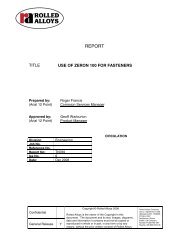
Figure 1 - Tack <strong>Welding</strong><br />
1. Root Tack 2. Bridge Tack<br />
a=<br />
3. Bullet Tack 4. Bullet Tack<br />
Included angle (a),<br />
degree<br />
f<br />
Radius (R),<br />
mm (in)<br />
R=<br />
l<br />
Land (l),<br />
mm (in)<br />
t<br />
Face (f),<br />
mm (in)<br />
20 - 25 3.0 (0.12) 1.0 (0.04) 1.5 (0.06)<br />
<strong>Welding</strong> Equipment<br />
There are no specific welding equipment requirements associated with <strong>ZERON</strong><br />
<strong>100</strong> over and above good stainless steel welding practice.<br />
As with sophisticated stainless steel welding, slope in/out facilities together<br />
with pre and post gas purge are important requirements for GTAW welding.<br />
Bridge tacks or spacer “bullet” blocks are recommended to maintain the root<br />
gap and joint alignment. Plate joints must be pre-set as normal to counteract<br />
distortion. All spacer blocks are to be stainless steel and they should be tacked<br />
at a controlled heat input in accordance with the WPS.<br />
Where tack welds are intended to form an integral part of the weld root bead,<br />
the root tack welds should be deposited in accordance with the approved WPS<br />
and the ends should be taper ground to ensure fusion with subsequent weld<br />
runs. Back purging should be employed when GTAW is used to deposit<br />
integral tacks.<br />
The tack welds should be balanced around the joint in order to maintain<br />
the root gap and joint alignment.<br />
3
Back Purging<br />
When welding <strong>ZERON</strong> <strong>100</strong>, it is recommended that commercial purity argon is<br />
used to displace the air behind the joint. The oxygen content of the resulting<br />
argon/air mixture must be monitored and controlled to ensure that sufficient<br />
nitrogen is retained in the backing gas “mixture” in order to inhibit loss of<br />
nitrogen from the weld pool. In practice the oxygen level of this mixture<br />
should be controlled at approximately 0.5% oxygen, monitored at the start<br />
of the welding sequence. In this way, a positive partial pressure of nitrogen is<br />
maintained behind the joint thus preventing nitrogen loss from the root bead,<br />
while the oxidation produced remains acceptable. Passes subsequent to the<br />
root pass can be made with minimum oxygen contents.<br />
An alternative method of maintaining the nitrogen content of the root is to<br />
use argon + 2% nitrogen as the shielding gas. This is only necessary on<br />
the root pass and pure argon may be used for the fill passes. Argon or<br />
argon + 2% nitrogen may be used as the backing gas.<br />
The backing gas composition should be monitored at the joint line using a<br />
portable oxygen monitor immediately prior to starting or re-starting welding<br />
in order that consistency can be maintained. Adhesive tape low in sulfur and<br />
chloride is used around the open joint seam, and the tape should be removed<br />
progressively during the welding sequence.<br />
Care should be taken to regulate the flow rate of the back purge gas to prevent<br />
gas turbulence and possible air entrainment through the open weld seam. The<br />
flow rate of the backing gas is typically 10-15 L/min (20-30 ft 3 /hr) although<br />
it is necessary to reduce flow rate at the tie-in location to avoid the risk of<br />
expulsion of molten metal and root underbead concavity.<br />
<strong>Welding</strong> Procedure<br />
Preheat<br />
Preheat is normally not required. It should only be applied where material<br />
is not dry or is below 5°C (41°F) prior to welding. Also in highly restrained<br />
heavy constructions or in particularly thick fabrications, preheating up to<br />
<strong>100</strong>°C (212°F) has been shown to be beneficial. Oxyfuel or carburizing<br />
flames should not impinge directly onto the material. Hot spots should<br />
be avoided.<br />
Arc Energy<br />
Arc energy is the common parameter controlled during the welding process.<br />
However, when welding duplex/super duplex it is the cooling rate which<br />
controls the microstructure and so the arc energy should be controlled in<br />
conjunction with the joint thickness.<br />
It is more effective in the control of optimum arc energy to maintain faster<br />
welding travel speeds and associated higher welding currents rather than<br />
lower welding current and slower travel speeds.<br />
To ensure a consistent arc energy, weaving of the weld bead should be kept<br />
to a minimum with a maximum of 3x filler wire diameter.<br />
Interpass Temperatures<br />
The interpass temperature, together with welding arc energy, is important in<br />
optimizing the cooling rate of a joint. Excessively high interpass temperature<br />
or arc energy may impair the corrosion resistance and impact toughness of<br />
the joint. The interpass temperature and welding arc energy must always<br />
be balanced in order to optimize the properties of the joint. If, for example,<br />
the arc energy cannot be maintained in the appropriate range, it would be<br />
necessary to reduce the interpass temperature. The maximum interpass<br />
temperature should be consistent with appropriate WPS and<br />
certainly less than 150°C (302°F).<br />
The interpass temperature is measured immediately prior to any welding<br />
directly at the points where a weld run is to commence and where it is<br />
supposed to terminate. A contact thermocouple should be used. The weld<br />
zone must be below the interpass temperature before restarting welding. The<br />
interpass temperature must be measured at each break in welding and not just<br />
when starting a new pass.<br />
Root Pass<br />
The GTAW process is normally specified to enhance control of root bead quality.<br />
While fabricator choice and the practices used in a particular shop are very<br />
important, it is generally found that:<br />
• 1.6 mm (1/16”) or 2.0 mm (5/64”) diameter filler wire is often<br />
used for material up to 4 mm (0.16”) thick.<br />
• 2.4 mm (3/32”) or 3.2 mm (1/8”) diameter filler wire is<br />
generally used for other material thicknesses.<br />
• Keyhole rooting practice is considered to be a preferred technique to<br />
obtain the optimum properties within the arc energy restraints<br />
in the root pass.<br />
Welder preference can be considered but is should be recognized that it is<br />
beneficial to deposit larger bead thicknesses within the arc energy restrictions.<br />
<strong>Welding</strong> arc energy (heat input) must be controlled to avoid adversely<br />
slow weld cooling rates developing during welding cycles.<br />
Table 5 - Typical Root Arc Energy and Layer Thickness<br />
Wall Thickness, mm (in) Arc Energy, kJ/mm* (kJ/in) Typical Pass Thickness, mm (in)<br />
2.88 (0.113) 0.4 - 0.6 (10 - 15) 2.0 (0.08)<br />
7.11 (0.28) 0.8- 1.2 (20 - 30) 3.0- 3.5 (0.12 - 0.14)<br />
17.5 (0.70) 1.5-1.8 (38 - 46) 3.0- 3.5 (0.12 - 0.14)<br />
Table 6 - Arc Energy Equations<br />
*Arc Energy =<br />
Amps x Volts x 60<br />
Amps x Volts x Arc time(s)<br />
kJ/mm (or)<br />
Travel Speed (mm/min) x <strong>100</strong>0 Run Out Length (mm) x <strong>100</strong>0<br />
* To convert to kJ/inch multiply by 25.4<br />
kJ/mm<br />
It should be considered that one important variable that is not commonly<br />
controlled during manual GTAW welding is filler metal addition. The typical root<br />
pass thickness indicated in the table above is based on:<br />
• <strong>Welding</strong> into the controlled root gaps specified in Tables 1, 2 and 3.<br />
• Addition of maximum and consistent levels of filler metal<br />
into the weld pool to promote optimum cooling rates.<br />
An excessively thick root pass is generally associated with too high an arc<br />
energy, whereas too thin a root pass is likely to result in burn through by the<br />
second pass. Root beads that are either too thick or too thin do, of course,<br />
result in practical welding problems and are likely to result in poor penetration<br />
bead profile.<br />
4
The root pass thicknesses shown are typical for the thickness being welded at<br />
the appropriate arc energy.<br />
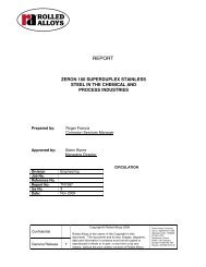
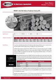
It may be considered advisable to deposit weld beads as a series of<br />
balanced segments, for example such as shown in figure 2, as this offers<br />
the advantage of:<br />
• Controlling joint gap closure<br />
• Reducing overall joint distortion<br />
• Maximizing production while maintaining<br />
interpass temperature requirements.<br />
Figure 2 - Balanced Joint Sequences<br />
The stop and start regions of all weld beads should be taper ground to<br />
facilitate smooth tie in. In GTAW welding industrial grade argon (99.995%) is<br />
recommended as shielding gas at typical flow rates of 8-12 L/min<br />
(17 -25 ft 3 /hr).<br />
Nozzles incorporating a gas lens ensure good gas coverage and effective weld<br />
protection with the avoidance of gas turbulence where extended tungsten<br />
electrode stick out is being applied. Slope down techniques<br />
at the termination of a weld to control phase balance should be used.<br />
Second Layer ‘Cold Pass’<br />
The root weld bead upper surface should, if necessary, be dressed smooth and<br />
stainless steel wire brushed. However, grinding is rarely required.<br />
As a general guide the second “cold” pass is deposited at a lower arc<br />
energy than that of the root pass. GTAW welding is normally used. Interpass<br />
temperature control as detailed previously must be maintained. It may be<br />
necessary to manipulate the weld pool in order to ensure that the pool is<br />
“washed in’. This can be achieved by “flicking” the weld pool up onto the<br />
side wall. Weaving must be minimized. Single bead or split layer welding<br />
techniques can be used within arc energy and joint configuration requirements.<br />
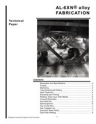
A single bead “cold pass” is preferred. Table 7 below illustrates the effect of<br />
different root pass and 2nd “cold” pass arc energy combinations.<br />
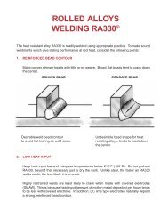
Table 7 - Variations in <strong>Welding</strong> GTAW root and second pass;<br />
Cold Pass Technique<br />
Root Pass:<br />
BAD: arc energy too high GOOD GOOD<br />
2nd Run:<br />
GOOD BAD: arc energy too high GOOD<br />
Overall Results:<br />
BAD: overheated root poor<br />
corrosion resistance<br />
BAD: reheated root poor<br />
corrosion resistance<br />
2<br />
3<br />
GOOD: optimum corrosion<br />
resistance<br />
4<br />
1<br />
Joint Filling Passes<br />
Argon back purging of single sided welds should be maintained throughout the<br />
welding of pipe and plate with weld deposit thicknesses up to 12 mm (0.5”),<br />
to avoid progressive root underbead oxidation through reheating. The back<br />
purging of double sided welds can be stopped earlier. Balanced weld sequences<br />
should be maintained for the initial 5 mm (0.2”) of joint thickness. Control<br />
of interpass temperature and arc energy should be maintained throughout the<br />
welding of the whole joint.<br />
Joint Filling Using SMAW Process<br />
<strong>ZERON</strong> <strong>100</strong> requires correct electrode handling procedures, in particular,<br />
protection against moisture pick-up. Electrodes should be used directly from<br />
unopened containers, vacuum pack containers or from a 150°C (300°F)<br />
minimum temperature storage oven.<br />
Electrodes should be issued and stored on the job in heated quivers in<br />
quantities suitable for 4 to 5 hours production or consumed within 8 to 10<br />
hours of removal from vacuum packaging. In all cases the manufacturers’<br />
recommendations for the particular type of flux coating should be followed.<br />
<strong>Welding</strong> techniques are based on electrode manipulation avoiding distinct<br />
weaving and associated high arc energy. Arc strikes should be avoided.<br />
Electrodes should be operated within the amperage range recommended<br />
by the manufacturers.<br />
Table 8 - Range of recommended SMAW electrode current settings<br />
Electrode Diameter, mm (in)<br />
Current Range, DC + (A)<br />
2.5 (0.10) 50-65<br />
3.2 (1/8) 70-90<br />
4.0 (5/32) <strong>100</strong>-140<br />
Joint Filling Using GMAW Process<br />
Both 1.0 mm (0.039”) and 1.2 mm (0.047”) diameter wires are available<br />
for welding. Multipass weld layers employing minimum weave and controlled<br />
arc energy are advocated for joint filling. Argon/helium (CO 2) gas mixtures<br />
have been successfully used for welding.<br />
Table 9 - GMAW Parameters<br />
Position<br />
Wire<br />
Diameter,<br />
mm (in)<br />
1G 1.2<br />
(0.047)<br />
5G/6G 1.0<br />
(0.039)<br />
Current,<br />
Amp<br />
Arc<br />
Voltage,<br />
Volt<br />
Travel<br />
Speed,<br />
mm/min<br />
(in/min)<br />
220-240 30-32 250- 400<br />
(10-16)<br />
80-95 30-32 200-300<br />
(8-12)<br />
Arc<br />
Energy,<br />
kJ/mm<br />
(kJ/in)<br />
1.0 - 1.5<br />
(25-38)<br />
0.6 - 0.8<br />
(15-20)<br />
Gas Flow,<br />
L/min<br />
(ft 3 /hr)<br />
20<br />
(42)<br />
20<br />
(42)<br />
<strong>Welding</strong> practice should aim to combine the productivity benefits of the process<br />
with maintenance of arc energy control.<br />
5
Joint Filling Using Submerged Arc (SAW) Process<br />
Submerged Arc <strong>Welding</strong>(SAW) combining fast deposition of high quality weld<br />
metal with mechanized process productivity, is a very viable alternative for<br />
joint filling with:<br />
• Material thickness in excess of 15-20 mm (0.6” - 0.8”)<br />
• Pipe or vessel diameters in excess of 150 mm (6”)<br />
• Circumferential or longitudinal seams can be welded<br />
in the downhand (ASME: 1G) position.<br />
The welding procedure with <strong>ZERON</strong> <strong>100</strong> is similar to that with standard<br />
austenitic stainless steels (316L etc) although in order to maintain requisite<br />
arc energy/weld cooling rate control, use of smaller diameter wires (e.g.<br />
2.4 mm (3/32”)) and modest welding parameters is recommended. The<br />
comparatively fast travel speed and low arc energy conditions facilitate the<br />
benefits of continuous (e.g. full circumferential) welding and a reduced level of<br />
interruptions associated with interpass temperature control.<br />
Control of weld bead shape is very important. The depth to width ratio must<br />
be less than 1.0, which requires careful control of arc voltage, to avoid risk of<br />
centerline solidification cracking. Avoid too thick a bead per layer. The process<br />
is normally introduced to fill out joints following deposition of 8 - 10 mm<br />
(0.3” - 0.4”) of GTAW and SMAW root weld layers. An interpass temperature<br />
of 150°C (300°F) maximum throughout the joint is recommended.<br />
The flux used must be maintained in a reliable dry condition i.e., either directly<br />
from new, unopened bags/drums or storage ovens operating at 250°C<br />
(480°F). Unfused flux recovered from the weld should be sieved and rebaked<br />
before further use.<br />
With the agglomerated fluxes involved, repeated recycling will lead to<br />
excessive build-up of fines and a shift in flux grain size balance, ultimately<br />
causing a deterioration in operating characteristics. To counter this effect,<br />
recycled flux should be diluted with new unused flux in a 1:1 ratio.<br />
The recommended 25 - 30 mm (1.0”- 1.2”) deep flux pile is intended to<br />
prevent arc flaring through the flux cover, leading to loss of arc/weld pool<br />
stability, possible entrainment of air into the arc cavity, potential risk of weld<br />
surface “gas flats” and, at worst, internal porosity. Above 30 mm (1.2”), flux<br />
pile depth will tend to inhibit release of gases generated during welding.<br />
With regard to electrode extensions, “stick-out” of less than 20 mm<br />
(0.75”), will cause resistive heating effects and metal droplet detachment<br />
may become unstable, resulting in weld bead wander (“slalom effect’’).<br />
Table 10 - SAW <strong>Welding</strong> Parameters<br />
Wire<br />
Diameter,<br />
mm (in)<br />
2.4<br />
(3/32)<br />
<strong>Welding</strong><br />
Current<br />
DC+, Amp<br />
Arc<br />
Voltage,<br />
Volt<br />
Travel<br />
Speed,<br />
mm/min<br />
(in/min)<br />
280-350 28-30 450- 500*<br />
(18 -20)<br />
Arc<br />
Energy,<br />
kJ/mm<br />
(kJ/in)<br />
0.9-1.2<br />
(23-30)<br />
Electrode<br />
Extension,<br />
mm (in)<br />
20-25<br />
(0.75-1.0)<br />
*Travel speeds up to 750 mm/min (30 in/min) may be required with smaller diameter,<br />
e.g. 6” (150 mm), pipe butt welds<br />
Flux<br />
Height,<br />
mm (in)<br />
25 -30<br />
(1.0-1.2)<br />
Repair welding<br />
<strong>ZERON</strong> <strong>100</strong> has excellent welding properties and consequently gives a low<br />
repair rate even when extensive NDE is applied on completed welds. If repairs<br />
are required then it has been found that it is easier and preferable to cut out<br />
and completely reweld all small diameter thin wall welds (Typically < <strong>100</strong> mm<br />
(4”) diameter and < 3 mm (.125”) wall thickness) rather than repair. When<br />
repairs are required on larger diameter, thicker welds then these should be<br />
carried out in accordance with a qualified weld repair procedure. It is essential<br />
on repair welds that the procedures are designed to prevent excessive heating<br />
of the previous weld zone especially where a thin ligament remains<br />
after any cut out.<br />
Post Weld Cleaning<br />
Care should be taken to ensure that all flux or light spatter is removed from<br />
the weld zone. Careful light grinding may be used in conjunction with wire<br />
brushing. Avoid the use of power wire brushes at the corrosion side so as not<br />
to smear the weld zone, which has been shown to reduce corrosion resistance.<br />
Pickling<br />
Pickling of the local weld area has been found to significantly improve<br />
corrosion resistance of the weld zone. Specific pickling pastes are available<br />
for super duplex stainless steels and give excellent improvements in properties<br />
when used in line with the manufacturer’s recommendations.<br />
Health and Safety<br />
Health and Safety requirements associated with welding Zeron <strong>100</strong> in relation<br />
to electrical equipment, pressurized gases, personnel protection, fire, fume<br />
and arc radiation must be observed. If in doubt, your company Safety Officer<br />
should be consulted.<br />
Summary<br />
Golden Rules<br />
Many thousands of Zeron <strong>100</strong> joints have been successfully welded utilizing<br />
and implementing this good welding practice. The main points to be<br />
remembered are:<br />
• Use good stainless steel fabrication practice<br />
• Use a consistent joint fit up as detailed in the qualified WPS<br />
• Control the backing gas composition and flow rate<br />
• Choose the correct arc energy relative to the joint thickness<br />
• Control the arc energy during production welding of the<br />
qualified WPS<br />
• Ensure consistent and maximum filler wire additions are made<br />
• Monitor and control the interpass temperatures and ensure that the<br />
maximum temperature quoted in qualified WPS is not exceeded<br />
• Utilize stringer bead techniques with minimal weaving<br />
(maximum 3x wire diameter)<br />
6
WELDING GUIDELINES<br />
<strong>ZERON</strong> ® <strong>100</strong><br />
UNS S32760<br />
The Global Leader in Specialty <strong>Alloys</strong><br />
Temperance, MI 48182<br />
Tel: 1-800-521-0332<br />
Email: sales@<strong>Rolled</strong><strong>Alloys</strong>.com<br />
www.<strong>Rolled</strong><strong>Alloys</strong>.com<br />
Bulletin No. 105 RAm 02/09 1M ©2009 <strong>Rolled</strong> <strong>Alloys</strong>