3/8" Square Potentiometers Cermet Fully Sealed P10
3/8" Square Potentiometers Cermet Fully Sealed P10
3/8" Square Potentiometers Cermet Fully Sealed P10

You also want an ePaper? Increase the reach of your titles
YUMPU automatically turns print PDFs into web optimized ePapers that Google loves.
<strong>P10</strong><br />
Vishay Sfernice<br />
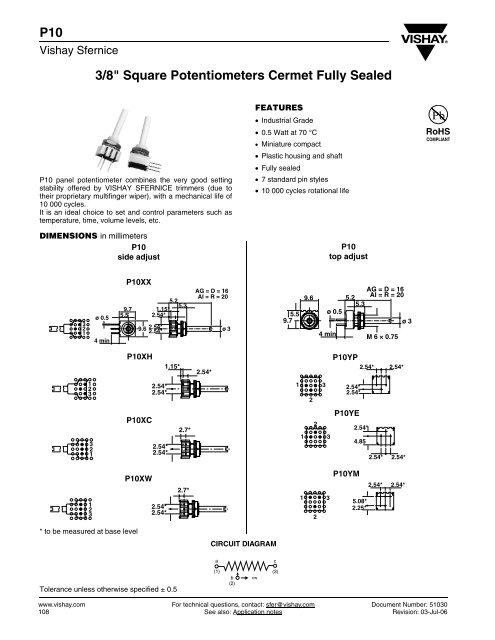
3/8" <strong>Square</strong> <strong>Potentiometers</strong> <strong>Cermet</strong> <strong>Fully</strong> <strong>Sealed</strong><br />
<strong>P10</strong> panel potentiometer combines the very good setting<br />
stability offered by VISHAY SFERNICE trimmers (due to<br />
their proprietary multifinger wiper), with a mechanical life of<br />
10 000 cycles.<br />
It is an ideal choice to set and control parameters such as<br />
temperature, time, volume levels, etc.<br />
DIMENSIONS in millimeters<br />
<strong>P10</strong><br />
side adjust<br />
FEATURES<br />
• Industrial Grade<br />
• 0.5 Watt at 70 °C<br />
• Miniature compact<br />
• Plastic housing and shaft<br />
• <strong>Fully</strong> sealed<br />
• 7 standard pin styles<br />
• 10 000 cycles rotational life<br />
<strong>P10</strong><br />
top adjust<br />
RoHS<br />
COMPLIANT<br />
3<br />
2<br />
1<br />
ø 0.5<br />
4 min<br />
<strong>P10</strong>XX<br />
9.7<br />
5.5<br />
5.2<br />
5.3<br />
1.15*<br />
2.54*<br />
9.6 2.54* 2.54*<br />
AG = D = 16<br />
AI = R = 20<br />
ø 3<br />
5.5<br />
9.7<br />
9.6<br />
ø 0.5<br />
4 min<br />
AG = D = 16<br />
5.2<br />
AI = R = 20<br />
5.3<br />
M 6 × 0.75<br />
ø 3<br />
<strong>P10</strong>XH<br />
1.15*<br />
2.54*<br />
<strong>P10</strong>YP<br />
2.54* 2.54*<br />
1<br />
2<br />
3<br />
2.54*<br />
2.54*<br />
1<br />
2<br />
3<br />
2.54*<br />
2.54*<br />
3<br />
2<br />
1<br />
<strong>P10</strong>XC<br />
2.54*<br />
2.54*<br />
2.7*<br />
1<br />
2<br />
3<br />
<strong>P10</strong>YE<br />
2.54*<br />
4.85<br />
2.54* 2.54*<br />
1<br />
2<br />
3<br />
<strong>P10</strong>XW<br />
2.54*<br />
2.54*<br />
2.7*<br />
1<br />
2<br />
3<br />
<strong>P10</strong>YM<br />
5.08*<br />
2.25*<br />
2.54* 2.54*<br />
* to be measured at base level<br />
CIRCUIT DIAGRAM<br />
a<br />
c<br />
Tolerance unless otherwise specified ± 0.5<br />
(1)<br />
b<br />
(2)<br />
cw<br />
(3)<br />
www.vishay.com For technical questions, contact: sfer@vishay.com Document Number: 51030<br />
108 See also: Application notes Revision: 03-Jul-06
<strong>P10</strong><br />
3/8" <strong>Square</strong> <strong>Potentiometers</strong> <strong>Cermet</strong> <strong>Fully</strong> <strong>Sealed</strong> Vishay Sfernice<br />
ELECTRICAL SPECIFICATIONS<br />
Resistive Element<br />
cermet<br />
Electrical Travel 250° ± 15°<br />
Resistance Range<br />
10 Ω to 2 MΩ<br />
Standard series 1 - 2 - 5<br />
Tolerance<br />
Standard ± 10 %<br />
On Request ± 5 %<br />
Power Rating<br />
Linear 0.5 W at + 70 °C<br />
Logarithmic<br />
not applicable<br />
Temperature Coefficient<br />
See Standard Resistance Element Table<br />
Limiting Element Voltage (Linear Law)<br />
250 V<br />
Contact Resistance Variation<br />
1 % Rn or 2 Ω<br />
End Resistance (Typical)<br />
1 Ω<br />
Dielectric Strength (RMS)<br />
1000 V<br />
Insulation Resistance<br />
10 6 MΩ<br />
MECHANICAL SPECIFICATIONS<br />
Mechanical Travel 290° ± 5°<br />
Operating Torque (max. Ncm) 2<br />
End Stop Torque (max. Ncm) 7<br />
Tightening Torque (max. Ncm) 25<br />
Unit Weight (max. g) 1<br />
ENVIRONMENTAL SPECIFICATIONS<br />
Temperature Range - 55 °C to + 125 °C<br />
Climatic Category 55/100/56<br />
Sealing<br />
fully sealed<br />
container IP67<br />
POWER RATING CHART<br />
POWER IN WATT<br />
0.5<br />
0<br />
0 25 50 70 100 125 155<br />
AMBIENT TEMPERATURE IN DEGREES CELSIUS<br />
PERFORMANCE<br />
TESTS<br />
Load Life<br />
Climatic Sequence<br />
Long Term Damp Heat<br />
Rapid Temperature Change<br />
Shock<br />
Vibration<br />
Rotational Life<br />
CONDITIONS<br />
1000 hours at rated power<br />
90’/30’ - ambient temperature 70 °C<br />
Phase A dry heat 100 °C<br />
Phase B damp heat<br />
Phase C cold - 55 °C<br />
Phase D damp heat 5 cycles<br />
56 days<br />
40 °C, 93 % RH<br />
5 cycles<br />
- 55 °C at + 125 °C<br />
50 g at 11 m secs<br />
3 successive shocks<br />
in 3 directions<br />
10 - 55 Hz<br />
0.75 mm or 10 g<br />
during 6 hours<br />
10 000 cycles<br />
TYPICAL VALUES AND DRIFTS<br />
ΔRT<br />
RT (%) ΔR1-2<br />
R1-2 (%)<br />
± 1 % ± 2 %<br />
Contact res. variation: < 1 % Rn<br />
± 1 % ± 2 %<br />
± 1 % ± 2 %<br />
Dielectric strength: 1000 V RMS<br />
Insulation resistance: > 10 4 MΩ<br />
± 1 %<br />
ΔV1-2<br />
V1-3<br />
≤ ± 2 %<br />
± 0.5 % ± 1 %<br />
± 0.5 %<br />
± 3 %<br />
Contact res. variation: < 2 % Rn<br />
ΔV1-2<br />
V1-3<br />
≤ ± 1 %<br />
Document Number: 51030 For technical questions, contact: sfer@vishay.com www.vishay.com<br />
Revision: 03-Jul-06 See also: Application notes 109
<strong>P10</strong><br />
Vishay Sfernice<br />
3/8" <strong>Square</strong> <strong>Potentiometers</strong> <strong>Cermet</strong> <strong>Fully</strong> <strong>Sealed</strong><br />
STANDARD RESISTANCE ELEMENT DATA<br />
STANDARD<br />
RESISTANCE<br />
VALUES<br />
MAX.<br />
POWER<br />
AT 70 °C<br />
LINEAR LAW<br />
MAX.<br />
WORKING<br />
VOLTAGE<br />
MAX. CUR.<br />
THROUGH<br />
WIPER<br />
TCR<br />
- 55 °C<br />
+ 125 °C<br />
Ω W V mA ppm/°C<br />
10<br />
20<br />
50<br />
0.5 2.2<br />
3.2<br />
5.0<br />
224<br />
160<br />
1000<br />
± 200<br />
100<br />
200<br />
500<br />
1K<br />
2K<br />
5K<br />
10K<br />
20K<br />
50K<br />
100K<br />
200K<br />
500K<br />
1M<br />
2M<br />
0.5<br />
0.28<br />
0.13<br />
0.06<br />
0.028<br />
7.0<br />
10.0<br />
15.8<br />
22.4<br />
31.8<br />
50.0<br />
70.7<br />
100<br />
158<br />
224<br />
250<br />
250<br />
250<br />
250<br />
70<br />
50<br />
32<br />
22<br />
16<br />
10<br />
7.0<br />
5.0<br />
3.2<br />
2.2<br />
1.3<br />
0.5<br />
0.25<br />
0.13<br />
± 100<br />
MARKING<br />
Printed:<br />
– VISHAY trademark<br />
– model<br />
– ohmic value<br />
– manufacturing date<br />
– pin 3<br />
The ohmic value is indicated by a 3 figures code: the first two<br />
digits are significant figures, the third digit is the multiplier:<br />
Example:<br />
100 = 10 Ω<br />
101 = 100 Ω<br />
102 = 1000 Ω<br />
503 = 50 000 Ω<br />
The manufacturing date is indicated by a 4 figures code. The<br />
first two digits are the year, the last two digits are the week.<br />
SHAFTS<br />
Standard shaft 20 mm length (R or AI code) and 16 mm<br />
length (D or AG code) is measured from the mounting face<br />
to the free end of the shaft.<br />
Vishay guarantee is lost if the customer modifies the shaft<br />
himself.<br />
HARDWARE<br />
Nuts and washer are supplied seperately (not mounted on<br />
the potentiometer) in a small bag placed in the packaging.<br />
PACKAGING<br />
– Carton boxes of 100 pieces<br />
ORDERING INFORMATION<br />
<strong>P10</strong><br />
MODEL<br />
XX<br />
VERSION<br />
R<br />
AXE<br />
500 kΩ<br />
OHMIC VALUE<br />
± 10 %<br />
TOLERANCE<br />
BO100<br />
PACKAGING<br />
e3<br />
LEAD FINISH<br />
XX YP<br />
XH YE<br />
XC YM<br />
XW<br />
R = AI = 20 mm<br />
D = AG = 16 mm<br />
e3: pure Sn<br />
SAP PART NUMBERING GUIDELINES<br />
P 1 0 X X A I 5 0 4 K B 3 0<br />
MODEL STYLE SHAFT OHMIC<br />
VALUE<br />
TOL<br />
PACKAGING<br />
CODE<br />
SPECIAL<br />
(IF APPLICABLE)<br />
See the end of this data book for conversion tables<br />
www.vishay.com For technical questions, contact: sfer@vishay.com Document Number: 51030<br />
110 See also: Application notes Revision: 03-Jul-06
Notice<br />
Legal Disclaimer Notice<br />
Vishay<br />
Specifications of the products displayed herein are subject to change without notice. Vishay Intertechnology, Inc.,<br />
or anyone on its behalf, assumes no responsibility or liability for any errors or inaccuracies.<br />
Information contained herein is intended to provide a product description only. No license, express or implied, by<br />
estoppel or otherwise, to any intellectual property rights is granted by this document. Except as provided in Vishay's<br />
terms and conditions of sale for such products, Vishay assumes no liability whatsoever, and disclaims any express<br />
or implied warranty, relating to sale and/or use of Vishay products including liability or warranties relating to fitness<br />
for a particular purpose, merchantability, or infringement of any patent, copyright, or other intellectual property right.<br />
The products shown herein are not designed for use in medical, life-saving, or life-sustaining applications.<br />
Customers using or selling these products for use in such applications do so at their own risk and agree to fully<br />
indemnify Vishay for any damages resulting from such improper use or sale.<br />
Document Number: 91000<br />
www.vishay.com<br />
Revision: 08-Apr-05 1