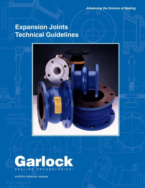
Garlock Expansion Joint Catalog - Enertech
Garlock Expansion Joint Catalog - Enertech
Garlock Expansion Joint Catalog - Enertech

Create successful ePaper yourself
Turn your PDF publications into a flip-book with our unique Google optimized e-Paper software.
<strong>Expansion</strong> <strong>Joint</strong>s<br />
Technical Guidelines
<strong>Garlock</strong> <strong>Expansion</strong> <strong>Joint</strong>s<br />
In service to world industries since 1887, <strong>Garlock</strong><br />
has lead the production and implemention of the latest<br />
<strong>Expansion</strong> <strong>Joint</strong> Technology for over fifty years.<br />
Just a few of the “firsts” developed by <strong>Garlock</strong>:<br />
■<br />
Development of high temperature elastomers<br />
to the levels now considered the industry<br />
standard<br />
■<br />
Developing the patented construction with<br />
bonded rectangular body rings<br />
■<br />
Creation of fused FEP liners designed<br />
specifically for chemical use<br />
■<br />
Abilities to combine fabric, FEP and<br />
elastomers effectively<br />
■<br />
Design of spool type joints to over 10 foot<br />
(120" or 3m) I.D.’s<br />
■<br />
Development of the flowing arch design<br />
Contents<br />
<strong>Expansion</strong> <strong>Joint</strong> Styles<br />
<strong>Expansion</strong> <strong>Joint</strong> Selection.................................B-2<br />
GUARDIAN ® 200 and 200HP............................B-3<br />
Styles 204 and 204HP.......................................B-4<br />
Style 204EVS....................................................B-5<br />
Style 206 EZ-FLO ® ...........................................B-8<br />
GUARDIAN ® 306 EZ-FLO ® ...............................B-6<br />
Style 104GS......................................................B-9<br />
Styles 214 and 215 Flexible Couplings...........B-10<br />
Styles 207 and 208..........................................B-12<br />
GARFLEX ® 8100.............................................B-13<br />
Style 9394........................................................B-14<br />
Style 8400 Flue Ducts.....................................B-15<br />
Style 8420 Split................................................B-16<br />
Navy & Coast Guard Approved Styles.............B-17<br />
Engineering Data<br />
Technical Data.................................................B-18<br />
Types of <strong>Expansion</strong> <strong>Joint</strong>s...............................B-20<br />
<strong>Expansion</strong> <strong>Joint</strong> Components..........................B-21<br />
Types of Pipe Movements...............................B-22<br />
Properties of Elastomers.................................B-23<br />
Temperature Ratings.......................................B-23<br />
<strong>Expansion</strong> <strong>Joint</strong> Installation.............................B-24<br />
Troubleshooting...............................................B-25<br />
Weights............................................................B-26<br />
Application Data Form.....................................B-27<br />
EZ-FLO ® , GARFLEX ® , and GUARDIAN ® are registered trademarks of<br />
<strong>Garlock</strong> Inc.<br />
B-1
Introduction<br />
<strong>Joint</strong> Selection<br />
An expansion joint is a specially engineered product<br />
inserted in a rigid piping system to achieve one or<br />
more of the following:<br />
■<br />
Absorb movement<br />
■<br />
Relieve system strain due to thermal change, load<br />
stress, pumping surges, wear or settling<br />
■<br />
Reduce mechanical noise<br />
■<br />
Compensate for misalignment<br />
■<br />
Eliminate electrolysis between dissimilar metals<br />
At <strong>Garlock</strong>, the range of our engineering emphasis<br />
extends from the selection of the fabric used for<br />
reinforcement to the choice of materials used in actual<br />
expansion joint construction.<br />
Rigid laboratory and field tests of <strong>Garlock</strong><br />
expansion joints are what back up our assurances of<br />
long life and reliable service. An important word on<br />
safety: all <strong>Garlock</strong> expansion joints carry safety ratings<br />
exceeding product specifications in such areas as<br />
temperature and pressure.<br />
<strong>Garlock</strong> nonmetallic expansion joints and flexible<br />
couplings are ideally suited for hundreds of applications<br />
in a wide range of industries, including:<br />
■<br />
Power generating stations<br />
■<br />
Pulp and paper<br />
■<br />
Chemical and industrial process piping<br />
■<br />
Waste water and sewage disposal<br />
■<br />
Marine applications<br />
■<br />
Heating, ventilating and air conditioning<br />
To select the proper expansion joint, consider:<br />
■<br />
Pipe size<br />
■<br />
Pumped medium: type of liquid, gas, or vapor in system<br />
■<br />
Temperature range<br />
■<br />
Pressure/vacuum range<br />
■<br />
Movements needed<br />
■<br />
Environment: degree of exposure to:<br />
• Weathering<br />
• Oil<br />
• Sunlight<br />
• Open flame<br />
• Liquids<br />
• Chemicals<br />
• Gases<br />
• Other<br />
• Vapors<br />
■<br />
Installed face-to-face dimensions<br />
■<br />
Degree of pipe misalignment<br />
• If greater than 0.125" (3.2 mm), correct or use<br />
a special joint<br />
■<br />
Drilling: if other than standard 125 Ib. ANSI,<br />
determine:<br />
• Flange O.D.<br />
• Bolt circle<br />
• Number of bolt holes<br />
• Diameter of hole<br />
■<br />
Need for retaining rings<br />
■<br />
Need for control units<br />
• Recommended for use with most expansion<br />
joints<br />
• Must be used in cases of insufficient pipe support<br />
■<br />
Need for special construction<br />
<strong>Garlock</strong> Recommendations<br />
204, 207, 214,<br />
200 200HP 204HP 206 208 215 306 7706-S 8100 9394 8400<br />
Standard Piping— ★ ★ ★ ★<br />
High Pressure<br />
Standard Piping— ★ ★ ★<br />
Low Pressure<br />
Chemical Piping ★ ★ ★ ★<br />
Standard Ducts ★ ★<br />
Nuclear ★ ★ ★<br />
Naval and ★ ★ ★ ★<br />
Coast Guard<br />
B-2
GUARDIAN ® 200 and 200HP<br />
<strong>Garlock</strong> GUARDIAN ® 200 expansion joints consist<br />
of a chemically-resistant FEP* liner mechanically<br />
bonded to an abrupt arch. A chlorobutyl cover and blue<br />
protective coating add resistance to environmental effects.<br />
(Alternate cover materials available.)<br />
Benefits<br />
■<br />
High-density FEP liner reduces permeation and offers<br />
optimal chemical resistance<br />
■<br />
Mechanically bound liner reduces delamination; no<br />
glue to be vulnerable to chemical attack<br />
■<br />
High pressure and vacuum resistance ensures suitability<br />
for broad range of applications<br />
■<br />
Available with GYLON ® 3545 gasket face for raised<br />
face flange connections<br />
Design<br />
■<br />
Tube<br />
• Seamless FEP lining extends to the outer edge<br />
of the flange; completely fused to the joint body<br />
• Abrupt arch design used for maximum movement<br />
capabilities<br />
■<br />
■<br />
Body<br />
• Chlorobutyl/polyester construction with welded,<br />
treated metal body rings for dimensional stability<br />
Cover<br />
• Homogeneous layer of chlorobutyl elastomer is<br />
standard<br />
• Elastomer extends to the outside diameter of the<br />
flange<br />
Fully Tested and Field Engineered<br />
All <strong>Garlock</strong> expansion joint styles have been rigorously<br />
lab and field-tested, and engineered to ensure<br />
long life and reliable service.<br />
Temperature<br />
Max. Temp.<br />
Standard chlorobutyl/polyester...............+250°F (+120°C)<br />
Chlorobutyl/fiberglass/Kevlar**<br />
with EPDM cover............................+300°F (+150°C)<br />
Fluoroelastomer w/ fiberglass/Kevlar......+400°F (+205°C)<br />
* Fluorinated Ethylene Propylene<br />
** Kevlar is a registered trademark of DuPont.<br />
GUARDIAN ® 200 †<br />
GUARDIAN ® 200HP †<br />
Pipe I.D.<br />
Inch mm<br />
Pressure Rating @<br />
3:1 Safefty Factor<br />
psi bar<br />
Pressure Rating @<br />
4:1 Safefty Factor<br />
psi bar<br />
Vacuum<br />
in. Hg mm Hg<br />
1/2-4 13-100 165 11 125 8.5 29.9 750<br />
5-12 125-300 140 10 105 7 29.9 750<br />
14 350 85 6 65 4.5 29.9 750<br />
16-24 400-600 65 4.5 50 3.5 29.9 750<br />
26-66 650-1,650 55 3.8 40 2.8 29.9 750<br />
68-96 1,700-2,400 45 3 35 2.5 29.9 750<br />
98-108 2,450-2,700 40 2.8 30 2 29.9 750<br />
110-144 2,750-3,600 30 2 25 1.7 29.9 750<br />
1/2-4 13-100 200 14 150 10.4 29.9 750<br />
5-12 125-300 190 13 145 10 29.9 750<br />
14 350 130 9 100 7 29.9 750<br />
16-20 400-500 110 8 85 5.5 29.9 750<br />
22-24 550-600 100 7 75 5 29.9 750<br />
26-40 650-1,000 90 6 65 4.5 29.9 750<br />
42-66 1,050-1,650 80 5.5 60 4 29.9 750<br />
68-96 1,700-2,400 70 5 50 3.5 29.9 750<br />
98-108 2,450-2,700 60 4 45 3 29.9 750<br />
110-144 2,750-3,600 50 3.5 35 2.5 29.9 750<br />
Made in the U.S.A.<br />
†<br />
Higher pressure designs are available. Call <strong>Garlock</strong> with application details.<br />
B-3
Styles 204 and 204HP<br />
Styles 204 and 204HP spool-type expansion joints<br />
can be constructed as single- or multiple-arch types.<br />
They connect pipe flanges in concentric or eccentric<br />
tapers, to join piping of unequal diameters.<br />
Benefits<br />
■<br />
Fully lab- and field-tested for long life and exceptional<br />
reliability<br />
■<br />
Seamless flange face eliminates need for gaskets<br />
■<br />
High pressure- and vacuum-resistance increases<br />
safety and ensures suitability for wide range of applications<br />
■<br />
Can be custom-designed for greater movement<br />
capability and easier installation<br />
■<br />
Variety of elastomer and fabric combinations meet<br />
the demands of temperature, pressure and media<br />
Design<br />
■<br />
Tube<br />
• Chlorobutyl resists cracking due to high temperatures,<br />
weathering, oxidation and chemicals<br />
• Abrupt arch configuration provides maximum<br />
movement, and pressure and vacuum resistance<br />
• Seamless tube creates a positive flange seal<br />
without gaskets<br />
■<br />
■<br />
Body<br />
• Chlorobutyl/polyester construction with welded,<br />
treated metal body rings for dimensional stability<br />
Cover<br />
• Chlorobutyl extends to outside flange diameter<br />
• Durable coating resists weathering and oxidation<br />
Special Liner and<br />
Cover Materials<br />
■<br />
Hypalon**<br />
■<br />
EPDM<br />
■<br />
Nitrile<br />
■<br />
Neoprene<br />
■<br />
Natural (tube only)<br />
■<br />
FDA materials available<br />
** Kevlar is a registered trademark of DuPont; Hypalon is a registered<br />
trademark of DuPont Dow Elastomers.<br />
Temperature<br />
Max. Temp.<br />
Standard chlorobutyl/polyester...............+250°F (+120°C)<br />
Chlorobutyl/fiberglass/Kevlar**<br />
with EPDM tube and cover...............+300°F (+150°C)<br />
Fluoroelastomer w/ fiberglass/Kevlar......+400°F (+205°C)<br />
Style 204 †<br />
Style 204HP †<br />
Pipe I.D.<br />
Inch mm<br />
†<br />
Higher pressure designs are available. Call <strong>Garlock</strong> with application details and to inquire<br />
about larger sizes.<br />
B-4<br />
Pressure Rating @<br />
3:1 Safefty Factor<br />
psi bar<br />
Pressure Rating @<br />
4:1 Safefty Factor<br />
psi bar<br />
Vacuum<br />
in. Hg mm Hg<br />
1/2-4 13-100 165 11 125 8.5 29.9 750<br />
5-12 125-300 140 10 105 7 29.9 750<br />
14 350 85 6 65 4.5 29.9 750<br />
16-24 400-600 65 4.5 50 3.5 29.9 750<br />
26-66 650-1,650 55 3.8 40 2.8 29.9 750<br />
68-96 1,700-2,400 45 3 35 2.5 29.9 750<br />
98-108 2,450-2,700 40 2.8 30 2 29.9 750<br />
110-144 2,750-3,600 30 2 25 1.7 29.9 750<br />
1/2-4 13-100 200 14 150 10.4 29.9 750<br />
5-12 125-300 190 13 145 10 29.9 750<br />
14 350 130 9 100 7 29.9 750<br />
16-20 400-500 110 8 85 5.5 29.9 750<br />
22-24 550-600 100 7 75 5 29.9 750<br />
26-40 650-1,000 90 6 65 4.5 29.9 750<br />
42-66 1,050-1,650 80 5.5 60 4 29.9 750<br />
68-96 1,700-2,400 70 5 50 3.5 29.9 750<br />
98-108 2,450-2,700 60 4 45 3 29.9 750<br />
110-144 2,750-3,600 50 3.5 35 2.5 29.9 750<br />
Optional Configurations<br />
Concentric Tapered<br />
Eccentric Tapered
Style 204EVS<br />
Benefits<br />
■<br />
Arch support ring reduces risk of arch collapse<br />
during vacuum service and system start-up<br />
■<br />
Single open arch provides full range of movement<br />
■<br />
The chlorobutyl cover and sealed bolt holes help to<br />
eliminate O2 intrusion<br />
■<br />
Natural rubber with nylon tire cord & polyester fabric<br />
reinforcement, combined with metal body rings,<br />
ensure best adhesion and dimensional stability<br />
■<br />
Offset configurations available to accommodate<br />
misaligned piping and equipment, eliminating<br />
realignment<br />
Ideal For<br />
■<br />
Systems with the dual challenges of extreme<br />
vacuum and aggressive dynamics<br />
■<br />
Condensate pump applications with less than ideal<br />
support and long cantilevered pipe runs<br />
Specifications<br />
Temperature, max.<br />
Pressure, max.<br />
Vacuum:<br />
Burst Rating: 3:1<br />
Available sizes:<br />
180°F (82°C)<br />
55 psig (3.8 bar)<br />
29.9" Hg<br />
14" through 48" ID<br />
Contact <strong>Garlock</strong> Customer Service for pricing and delivery.<br />
Use of control units with compression sleeves are<br />
recommended.<br />
Movement<br />
Pipe I.D. Comp. Lateral Elong.<br />
Inch mm Inch mm Inch mm Inch mm<br />
14-18 350-450 3/4 19 1/2 12 3/8 9<br />
20-24 500-600 7/8 22 1/2 12 7/16 11<br />
26-40 650-1,000 1 25 1/2 12 1/2 12<br />
42-48 1,050-1,200 1-1/8 29 1/2 12 1/2 12<br />
Misalignment<br />
Pipe I.D. Comp. Lateral Elong.<br />
Inch mm Inch mm Inch mm Inch mm<br />
14-18 350-500 1/8 3 1/8 3 1/8 3<br />
24-28 600-1,200 3/16 5 1/4 6 1/4 6<br />
* Movements listed are non-concurrent. For concurrent<br />
movements, contact <strong>Garlock</strong>.<br />
Retaining <strong>Expansion</strong> Internal Arch Pipe Control Unit<br />
Ring <strong>Joint</strong> Ring Flange Assembly<br />
B-5
GUARDIAN ® 306 EZ-FLO ®<br />
<strong>Garlock</strong> GUARDIAN ® 306 EZ-FLO ® spool-type<br />
expansion joints feature an FEP lining that is fused to<br />
the body of the expansion joint.<br />
The GUARDIAN ® 306 EZ-FLO ® is designed for<br />
the chemical processing and pulp & paper industries,<br />
where its ability to resist corrosive attack at normal or<br />
elevated temperatures and pressures is unequaled.<br />
Benefits<br />
■<br />
FEP liner is non-contaminating and suits a wide<br />
range of applications<br />
■<br />
Flowing arch design prevents media buildup and<br />
reduces turbulence and vibration<br />
■<br />
250 psig (17 bar) pressure rating ensures longer<br />
service life and consolidates inventory<br />
■<br />
Liner extends to outer diameter of flange to prevent<br />
chemical attack on expansion joint flanges<br />
■<br />
Mechanically bonded liner resists delamination<br />
Design<br />
■<br />
■<br />
■<br />
■<br />
Tube<br />
• Seamless FEP lining extends to the outer edge<br />
of the flange; completely fused to the expansion<br />
joint body<br />
• Incorporates a flowing arch design to resist product<br />
build-up<br />
Body<br />
• Impregnated nylon tire cord fabric cross-wrapped<br />
in bias-ply construction<br />
Cover<br />
• Homogeneous layer of chlorobutyl elastomer<br />
extends to the outside edge of the flange<br />
• Coated with a weather-resistant protectant<br />
Special Designs<br />
• Non-standard face-to-face dimensions<br />
(pressure / vacuum ratings may be affected)<br />
• Non-standard drill patterns<br />
• Blind flanges (no drilling)<br />
• Lightweight designs available for low pressure<br />
and non-metallic pipe applications<br />
• Available with GYLON ® 3545 gasket face for<br />
raised face flange connections<br />
Pressure and Vacuum Rating*<br />
Pipe I.D. Pressure Vacuum<br />
Inch mm psi bar in. Hg mm Hg<br />
Style 306 3-10 75-250 250 17 26 650<br />
EZ-FLO ® 12 300 250 17 17 425<br />
14 350 130 9 17 425<br />
16-20 400-500 110 8 15 375<br />
* Pressure and vacuum ratings are for neutral FF dimensions only.<br />
Consult <strong>Garlock</strong> for alternate sizes and corresponding pressure/vacuum ratings.<br />
Consult <strong>Garlock</strong> for larger sizes. Metric sizes available on request.<br />
Listed pressure ratings are based on a 4:1 safety factor at max. design temp.<br />
Temperature<br />
Max. Temp.<br />
Chlorobutyl/nylon tire cord......................+250°F (+120°C)<br />
Chlorobutyl/Kevlar** tire cord<br />
with EPDM cover.......................+300°F (+150°C)<br />
** Kevlar is a registered trademark of DuPont.<br />
WARNING:<br />
Properties/applications shown throughout this brochure are typical. Your specific application<br />
should not be undertaken without independent study and evaluation for suitability.<br />
For specific application recommendations consult <strong>Garlock</strong>. Failure to select the proper<br />
sealing products could result in property damage and/or serious personal injury.<br />
Performance data published in this brochure has been developed from field testing,<br />
customer field reports and/or in-house testing.<br />
While the utmost care has been used in compiling this brochure, we assume no responsibility<br />
for errors. Specifications subject to change without notice. This edition cancels<br />
all previous issues. Subject to change without notice.<br />
GARLOCK is a registered trademark for packings, seals, gaskets, and other products<br />
of <strong>Garlock</strong>.<br />
B-6
Movement Capabilities<br />
Pipe I.D.<br />
Movement<br />
Type Movement Inch mm Inch mm<br />
Compression 3-4 75-100 3/4 19<br />
6-20 150-500 1 25<br />
Elongation 3-4 75-100 3/8 10<br />
6-20 150-500 1/2 12<br />
Lateral 3-4 75-100 1/2 12<br />
6-20 150-500 1/2 12<br />
Pipe I.D. Movement<br />
Type Movement Inch mm Degrees<br />
Angular 3-4 75-100 8<br />
6-8 150-200 5<br />
10-12 250-300 4<br />
14-16 350-400 2.5<br />
18-20 450-500 2<br />
Torsional 3-12 75-300 3<br />
14-16 350-400 2<br />
18-20 450-500 1<br />
Compression<br />
Elongation<br />
<br />
<br />
<br />
<br />
<br />
<br />
<br />
<br />
<br />
<br />
<br />
<br />
<br />
<br />
<br />
<br />
<br />
<br />
<br />
<br />
<br />
<br />
<br />
<br />
<br />
<br />
<br />
<br />
<br />
<br />
<br />
<br />
<br />
<br />
<br />
<br />
<br />
<br />
<br />
<br />
<br />
<br />
<br />
<br />
<br />
<br />
Fully Tested and Field Engineered<br />
All <strong>Garlock</strong> expansion joint styles have been rigorously<br />
lab- and field-tested, and engineered to ensure<br />
long life and reliable service.<br />
Control Units<br />
Control units must be used to protect expansion<br />
joints from excessive movement if piping is not properly<br />
anchored. See page B-19 for information.<br />
Notes:<br />
1. Sizes 3"-20" indicate nominal ANSI pipe sizes.<br />
2. 3" and 4" I.D. have 3/4" maximum compression and 3/8" maximum<br />
elongation.<br />
3. Forces to compress and elongate are based on zero pressure conditions<br />
and ambient temperatures in the pipeline.<br />
4. To convert force in pounds to kilograms, divide by 2.205.<br />
5. Metric sizes avilable by special request.<br />
B-7
Style 206 EZ-FLO ®<br />
EZ-FLO ® expansion joints contain a single wide<br />
flowing arch, eliminating the need for filled arches on<br />
slurry services. <strong>Garlock</strong> EZ-FLO ® expansion joints have<br />
successfully served all major industries, including pulp<br />
and paper, steel, waste and water, HVAC, power generation,<br />
chemical, petrochemical and marine.<br />
Benefits<br />
■<br />
Self-flushing design eliminates media buildup and<br />
reduces fluid turbulence<br />
■<br />
High pressure- and vacuum-resistance ensures<br />
longer life and reduces inventory requirements<br />
■<br />
Lightweight design installs easily, costs less to ship<br />
Design<br />
■<br />
■<br />
■<br />
B-8<br />
Tube<br />
• Standard chlorobutyl liner extends to outer edge<br />
of the flange for excellent chemical resistance<br />
• Flowing arch design adds pressure resistance<br />
and reduces product buildup<br />
Body<br />
• Rubber impregnated tire cord and polyester<br />
cross-wrapped in bias-ply construction<br />
Cover<br />
• Homogeneous layer of chlorobutyl elastomer<br />
extends to the outside edge of the flange<br />
• Coated with a weather-resistant protectant<br />
Fully Tested and Field Engineered<br />
All <strong>Garlock</strong> expansion joint styles have been rigorously<br />
lab- and field-tested, and engineered to ensure<br />
long life and reliable service.<br />
Special Liner * and Cover Materials<br />
■<br />
Neoprene<br />
■<br />
Nitrile<br />
■<br />
EPDM<br />
■<br />
Natural (tube only)<br />
■<br />
Hypalon**<br />
■<br />
FDA materials available<br />
Temperature<br />
Max. Temp.<br />
Chlorobutyl/nylon tire cord......................+250°F (+120°C)<br />
Chlorobutyl/Kevlar** tire cord/<br />
EPDM tube and cover.......................+300°F (+150°C)<br />
* When EZ-FLO ® expansion joints are furnished with special liners,<br />
temperature and pressure ratings may change.<br />
** Kevlar is a registered trademark of DuPont;<br />
Hypalon is a registered trademark of DuPont Dow Elastomers.<br />
Pressure and Vacuum Rating<br />
Pipe I.D. Pressure Vacuum<br />
Inch mm psi bar in. Hg mm Hg<br />
Style 206 2-10 50-250 250 17 26 650<br />
EZ-FLO ®† 12 300 250 17 12 300<br />
14 350 130 9 12 300<br />
16-20 400-500 110 8 12 300<br />
22-24 550-600 100 7 12 300<br />
26-40 650-1,000 90 6 12 300<br />
42-66 1,050-1,650 80 5.5 12 300<br />
68-84 1,700-2,100 70 5 12 300<br />
86-120 2,150-3,000 60 4 12 300<br />
†<br />
Pressure and vacuum ratings are for standard FF dimensions only.<br />
Consult <strong>Garlock</strong> for alternate sizes and corresponding pressure/vacuum<br />
ratings. Consult <strong>Garlock</strong> for larger sizes. Metric sizes available on<br />
request.<br />
Movement Capabilities<br />
Pipe I.D. Movement<br />
Type Movement Inch mm Inch mm<br />
Compression 2-5 50-125 3/4 19<br />
6-18 150-450 1 25<br />
20-24 500-600 1-1/8 30<br />
26-40 650-1,000 1-1/4 32<br />
42 & Up 1,050 & Up 1-3/8 35<br />
Elongation 2-5 50-125 3/8 10<br />
6-18 150-450 1/2 12<br />
20-24 500-600 1/2 12<br />
26 & Up 650 & Up 1/2 12<br />
Transverse 2-8 50-200 1/2 12<br />
(Lateral) 10 & Up 250 & Up 1/2 12<br />
Control Units<br />
Control units must be used to protect expansion<br />
joints from excessive movement if piping is not properly<br />
anchored. See page B-19 for information.
Style 104GS<br />
General service elastomeric expansion joint<br />
General service expansion joints must withstand<br />
a variety of different operating conditions across multiple<br />
industries. The 104GS from <strong>Garlock</strong> is designed<br />
to handle these most common requirements, and more.<br />
Although competitively priced, the 104GS has been rigorously<br />
tested to insure it provides the same quality and<br />
consistency you expect from <strong>Garlock</strong> products.<br />
Benefits & Design<br />
■<br />
The versatility of the neoprene tube 1 and cover 4<br />
make the 104GS ideally suited for most general<br />
service industrial applications.<br />
■<br />
Reinforcement materials of nylon fabric 5 combined<br />
with carbon steel body wire 3 and support rings 2<br />
allow the 104GS to withstand significant operating<br />
pressures and 26" Hg vacuum for all sizes.<br />
■<br />
The wide, single arch 6 design allows for greater<br />
movements and helps to reduce the affects of moderate<br />
sediment transfer.<br />
■<br />
Available in 2" thru 24" and sold complete 7 with<br />
galvanized carbon steel retaining rings simplifying<br />
the order process.<br />
7<br />
6<br />
5<br />
4<br />
3<br />
1<br />
2<br />
Specifications - 200ºF Maximum Temperature Rating<br />
<strong>Expansion</strong> <strong>Joint</strong><strong>Expansion</strong> <strong>Joint</strong> Application Application Data Data Movement Ratings<br />
Size I.D. Face-to-Face Size I.D. Face-to-Face Pressure Pressure Vacuum Face-to-FaceCompression Compression Lateral Lateral Elongation<br />
Angular Tortional Tortional<br />
Inch mm Inch Inch mm mm Inch psimm bar psi Inch bar HgInch mm Hg Hgmm Inch Hg Inchmm mm Inch Inch mm mm Inch mm<br />
Degrees Degrees Degrees<br />
2 50 6 150 195 13 26 660 1-1/4 32 3/4 19 1/2 13 10 3<br />
3 75 6 150 195 13 26 660 1-1/4 32 3/4 19 1/2 13 8 3<br />
4 100 6 150 195 13 26 660 1-1/4 32 3/4 19 1/2 13 6 3<br />
5 125 6 150 165 11 26 660 1-3/8 35 1 25 5/8 16 8 3<br />
6 150 6 150 165 11 26 660 1-3/8 35 1 25 5/8 16 7 3<br />
8 200 6 150 165 11 26 660 1-3/8 35 1 25 5/8 16 5 3<br />
10 250 8 200 165 11 26 660 1-3/8 35 1 25 5/8 16 5 3<br />
12 300 8 200 165 11 26 660 1-1/2 38 1 25 3/4 19 5 3<br />
14 350 8 200 100 7 26 660 1-1/2 38 1 25 3/4 19 4 2<br />
16 400 8 200 75 5 26 660 1-1/2 38 1 25 3/4 19 4 2<br />
18 450 8 200 75 5 26 660 1-1/2 38 1 25 3/4 19 3 1<br />
20 500 8 200 75 5 26 660 1-1/2 38 1 25 3/4 19 3 1<br />
24 600 10 250 75 5 26 660 1-3/4 44 1 25 1 25 4 1<br />
<strong>Expansion</strong> <strong>Joint</strong><br />
Size I.D.<br />
OD<br />
ANSI Class 150 Flange Drilling<br />
Bolt Circle<br />
2 50 6 152 4-3/4 121 3/4 19 4 450 18 340 13 560 22 40<br />
3 75 7-1/2 191 6 152 3/4 19 4 670 26 500 20 828 15 65<br />
4 100 9 229 7-1/2 191 3/4 19 8 900 35 730 29 1104 20 45<br />
5 125 10 254 8-1/2 216 7/8 22 8 1120 44 900 35 1376 25 50<br />
6 150 11 279 9-1/2 241 7/8 22 8 1400 55 1060 42 1652 30 55<br />
8 200 13-1/2 343 11-3/4 298 7/8 22 8 1510 59 1180 46 1837 33 85<br />
10 250 16 406 14-1/4 362 1 25 12 1900 75 1460 57 2296 41 80<br />
12 300 19 483 17 432 1 25 12 2300 91 1740 69 2755 50 115<br />
14 350 21 533 18-3/4 476 1-1/8 29 12 2010 79 1570 62 2755 50 145<br />
16 400 23-1/2 597 21-1/4 540 1-1/8 29 16 2300 91 1740 69 2755 50 135<br />
18 450 25 635 22-3/4 578 1-1/4 32 16 2570 101 1960 77 3101 56 140<br />
20 500 27-1/2 699 25 635 1-1/4 32 20 2860 113 2180 86 3440 62 135<br />
24 600 32 813 29-1/2 749 1-3/8 35 20 3420 135 2630 104 4130 74 190<br />
Pressure ratings are based on a minimum 3 to 1 safety factor at maximum design temperature.<br />
Spring Rates<br />
Bolt Hole<br />
No. of<br />
Diameter Bolt Holes Compression Lateral Elongation<br />
Inch mm Inch mm Inch mm Inch mm lb/Inch kg/mm lb/Inch kg/mm lb/Inch kg/mm Ft-Lbs<br />
Bolt<br />
Torque<br />
B-9
Styles 214 and 215<br />
These PTFE concentric spool-type flexible couplings<br />
are designed to reduce noise and compensate<br />
for expansion, contraction and minor piping misalignment<br />
in chemical processing, air conditioning and<br />
heating systems.<br />
Style 214<br />
■<br />
Two convolutions<br />
■<br />
Temperature: -100°F (-70°C) to +450°F (+230°C)<br />
Pressure: To 178 psig (12 bar),<br />
Full vacuum to +350°F (+180°C)<br />
Style 215<br />
■<br />
Three convolutions<br />
■<br />
Temperature: -100°F (-70°C) to +450°F (+230°C)<br />
Pressure: To 132 psig (9 bar),<br />
Full vacuum to +180°F (+80°C)<br />
Benefits<br />
■<br />
Convolution shape provides extra-long flex life at<br />
high temperatures<br />
■<br />
Proprietary contour molding process ensures consistent<br />
wall thickness for blowout resistance<br />
■<br />
PTFE body withstands corrosion, water, steam, and<br />
most chemicals and gases<br />
■<br />
Higher pressure and temperature ratings mean<br />
extended service life in most piping systems<br />
■<br />
Preset restriction bolts prevent over-extension<br />
■<br />
Available silicone-free<br />
Design<br />
■<br />
Complete assembly includes fluorocarbon resin<br />
PTFE body, plated ductile iron flanges, polyethylene-covered<br />
restriction bolts and corrosion-resistant<br />
reinforcing rings<br />
■<br />
Standard sizes from 1" (25 mm) through 8" (200<br />
mm) pipe l.D.<br />
Pressure and Vacuum Rating<br />
<strong>Garlock</strong> PTFE expansion joints and couplings have<br />
pressure ratings high enough to handle most applications.<br />
As the pipe size gets larger, <strong>Garlock</strong> increases<br />
the bellows thickness and the strength of the reinforcing<br />
rings to compensate for the change in internal<br />
forces. This permits the same high pressure rating for<br />
all sizes.<br />
Temperature 214 Pressure 215 Pressure<br />
psi bar psi bar<br />
50°F 10°C 178 12 132 9<br />
100°F 50°C 165 11 120 8<br />
150°F 65°C 150 10 103 7<br />
200°F 90°C 130 9 90 6<br />
250°F 120°C 110 8 75 5<br />
300°F 150°C 92 6 60 4<br />
350°F 180°C 78 5 50 3.5<br />
400°F 205°C 65 4.5 42 3<br />
450°F 230°C 60 4 35 2<br />
WARNING:<br />
Properties/applications shown throughout this brochure are typical. Your specific application<br />
should not be undertaken without independent study and evaluation for suitability.<br />
For specific application recommendations consult <strong>Garlock</strong>. Failure to select the proper<br />
sealing products could result in property damage and/or serious personal injury.<br />
Performance data published in this brochure has been developed from field testing,<br />
customer field reports and/or in-house testing.<br />
While the utmost care has been used in compiling this brochure, we assume no responsibility<br />
for errors. Specifications subject to change without notice. This edition cancels<br />
all previous issues. Subject to change without notice.<br />
GARLOCK is a registered trademark for packings, seals, gaskets, and other products<br />
of <strong>Garlock</strong>.<br />
B-10
Movement<br />
Style 214 PTFE Flexible Couplings<br />
Pipe Size (Inches) 1 1-1/2 2 2-1/2 3 4 5 6 8<br />
Nominal Installed<br />
Face to-Face<br />
1-3/8 1-3/8 1-9/16 2-1/4 2-1/4 2-5/8 3-1/4 2-3/4 4<br />
Max. Restriction Bolt<br />
Setting<br />
1-1/4 1-5/16 1-15/32 2-7/32 2-1/4 2-23/32 3-5/16 2-3/4 4<br />
Max. Axial Movement<br />
+ or -<br />
1/4 1/4 1/4 5/16 3/8 1/2 1/2 1/2 1/2<br />
Max. Transverse<br />
Deflection, + or -*<br />
1/8 1/8 1/8 1/8 3/16 1/4 1/4 1/4 1/4<br />
Maximum angular movement aproximately 7°.<br />
* Based on unit being in normal installed position with no axial movement or angular deflection.<br />
Style 215 PTFE Flexible Couplings<br />
Pipe Size (Inches) 1 1-1/2 2 2-1/2 3 4 5 6 8<br />
Nominal Installed<br />
Face to-Face<br />
1-3/4 2 2-3/4 3-3/16 3-5/8 3-5/8 4 4 6<br />
Max. Restriction Bolt<br />
Setting<br />
1-7/8 2-5/32 3-5/32 3-9/16 4-1/4 4-1/4 4-9/16 4-5/8 6-5/8<br />
Max. Axial Movement<br />
+ or -<br />
1/2 1/2 3/4 3/4 1 1 1 1-1/8 1-1/8<br />
Max. Transverse<br />
Deflection, + or -*<br />
1/4 1/4 3/8 3/8 1/2 1/2 1/2 9/16 9/16<br />
Maximum angular movement aproximately 14°.<br />
* Based on unit being in normal installed position with no axial movement or angular deflection.<br />
PTFE Control Units and Flanges<br />
All PTFE joints and couplings are furnished with<br />
ductile iron flanges and control units ready for immediate<br />
installation on the job site. Flanges in other alloys<br />
are available by special order.<br />
Flanges are protected to resist atmosphere corrosion<br />
and are tapped to 150 Ibs. ANSI Standard drilling.<br />
Control units are assembled with flanges to prevent<br />
joints from excessive axial elongation. They are<br />
designed to accept the static pressure thrust in the<br />
piping system.<br />
Tie rods are set at the factory at the maximum faceto-face<br />
working limits, with lock nuts as insurance<br />
against overextension of the expansion joint. The<br />
tie rods are covered with polyethylene to eliminate<br />
metal-to-metal contact between the rods and<br />
flanges—the most frequent cause of noise transmission<br />
and electrolysis.<br />
Flange Dimensions and Drilling<br />
Pipe Size (Inches) 1 1-1/2 2 2-1/2 3 4 5 6 8<br />
Flange<br />
Dimension 5-11/16 6-7/16 7-7/8 9-1/8 10 11-1/8 12-7/8 13-7/8 15-1/2<br />
Thickness 3/8 3/8 1/2 5/6 5/8 11/16 11/16 11/16 11/16<br />
ANSI Std. Drilling<br />
Bolt Circle Dia. 3-1/8 3-7/8 4-3/4 5-1/2 6 7-1/2 8-1/2 9-1/2 11-3/4<br />
No. Bolt Holes 4 4 4 4 4 8 8 8 8<br />
Bolt Hole Thread 1/2-13 1/2-13 5/8-11 5/8-11 5/8-11 5/8-11 3/4-10 3/4-10 3/4-10<br />
* Special order only<br />
B-11
Styles 207 and 208<br />
Styles 207 and 208 are U-type expansion joints<br />
constructed of specialty rubber and fabric. Available in<br />
round or rectangular configurations, they are used as<br />
flexible connectors between a turbine and condenser,<br />
or other similar applications.<br />
Style 207<br />
■<br />
Internally flanged for full vacuum and low pressure<br />
applications<br />
■<br />
Temperature: To +250°F (+120°C)*<br />
Pressure: 29.9"Hg to 15 psig (1.0 bar)<br />
Style 208<br />
■<br />
Externally flanged, primarily for vacuum service<br />
■<br />
Temperature: To +250°F (+120°C)*<br />
Pressure: 29.9"Hg to 25 psig (1.7 bar)<br />
■<br />
Available in very narrow face-to-face dimensions;<br />
staggered drilling facilitates installation<br />
■<br />
Also recommended to reduce vibration and noise on<br />
lightweight piping, i.e. those carrying coal-laden air<br />
to pulverized coal burners<br />
Fully Tested and Field Engineered<br />
All <strong>Garlock</strong> expansion joint styles have been rigorously<br />
lab- and field-tested, and engineered to ensure<br />
long life and reliable service.<br />
Note: For recommendations for specific applications, including range of<br />
available elastomers, consult <strong>Garlock</strong>.<br />
Movement Capabilities<br />
Type Movement<br />
Pipe I.D. Movement<br />
Inch mm Inch mm<br />
Compression 2-20 50-500 1/2 12<br />
22 & Up 550 & Up 3/4 19<br />
Elongation 2-20 50-500 1/4 6<br />
22 & Up 550 & Up 1/4 6<br />
Lateral 2-20 50-500 1/2 12<br />
22 & Up 550 & Up 1/2 12<br />
* For higher temperature capabilities, consult <strong>Garlock</strong>.<br />
WARNING:<br />
Properties/applications shown throughout this brochure are typical. Your specific application<br />
should not be undertaken without independent study and evaluation for suitability.<br />
For specific application recommendations consult <strong>Garlock</strong>. Failure to select the proper<br />
sealing products could result in property damage and/or serious personal injury.<br />
Performance data published in this brochure has been developed from field testing,<br />
customer field reports and/or in-house testing.<br />
While the utmost care has been used in compiling this brochure, we assume no responsibility<br />
for errors. Specifications subject to change without notice. This edition cancels<br />
all previous issues. Subject to change without notice.<br />
GARLOCK is a registered trademark for packings, seals, gaskets, and other products<br />
of <strong>Garlock</strong>.<br />
B-12
GARFLEX ® 8100<br />
GARFLEX ® expansion joints feature rugged yet<br />
flexible nylon cord reinforcement in a molded, spherical<br />
bellows design that ensures an exceptional burst<br />
pressure rating. The streamlined flowing arch design<br />
reduces turbulence and allows smooth, quiet flow—no<br />
need to fill the arch and restrict its movement.<br />
Benefits<br />
■<br />
Flowing arch design prevents sediment buildup and<br />
reduces turbulence<br />
■<br />
Floating flanges can be rotated to accommodate<br />
torsional misalignment<br />
■<br />
Molded spherical bellows accommodate up to one<br />
inch of axial movement and transverse deflection<br />
■<br />
Nylon-reinforced nitrile tube earns high pressure rating<br />
without sacrificing flexibility; resists most hydrocarbons,<br />
oils and gasoline<br />
■<br />
Supplied silicone-free<br />
Design<br />
■<br />
■<br />
■<br />
Tube<br />
• Nitrile bellows with rugged nylon tire cord reinforcement<br />
ensure strength yet flexibility<br />
• Incorporates a flowing arch design to eliminate<br />
product buildup<br />
Cover<br />
• Homogeneous layer of neoprene coated with a<br />
protectant withstands weathering and ozone<br />
Flanges<br />
• Iron flanges are corrosion-resistant<br />
Note:<br />
Style 8100 expansion joints are supplied with rotating flanges drilled<br />
to ANSI Class 150# specifications. Can be installed against raised<br />
face pipe flanges.<br />
Bellow Sizes<br />
Nominal Nominal Bellow I.D. (inch)<br />
F-F (in.) 2 2.5 3 4 5 6 8 10 12<br />
Series 50 5 ■ ■ ■ ■ ■ ■ ■ ■ ■<br />
Series 60 6 ■ ■ ■ ■ ■ ■ ■ NA NA<br />
Series 80 8 NA NA NA NA NA NA NA ■ ■<br />
NA = Not available<br />
Temperature / Pressure<br />
Nylon-Reinforced Nitrile<br />
Operating Temperature<br />
Pressure<br />
°F °C psi bar<br />
To 120°F To 50°C 232 16<br />
120°F to 160°F 50°C to 70°C 174 12<br />
160°F to 195°F 70°C to 90°C 139 9.5<br />
195°F to 210°F 90°C to 100°C 70 5<br />
210°F to 230°F 100°C to 110°C 25 1.7<br />
Vacuum Rating* – Nitrile<br />
Pipe I.D.<br />
Vacuum<br />
Inch mm in. Hg mm Hg<br />
2 to 2-1/2 50 to 63 23 575<br />
3 75 20 500<br />
4 100 17 425<br />
5 to 6 125 to 150 11 275<br />
8 200 8 200<br />
10 to 12 250 to 300 5 125<br />
* At nominal FF dimensions only.<br />
Movement – Nylon-Reinforced Nitrile<br />
Movement<br />
Type Movement Inch mm<br />
Compression 1 25<br />
Elongation 1 25<br />
Transverse Deflection (at recom- ± 1 ± 25<br />
mended installed position)<br />
Movements are non-concurrent.<br />
Pipe I.D.<br />
Max.<br />
Type Movement Inch mm Allowed<br />
Angular Deflection 2 50 35°<br />
(at recommended 2-1/2 to 3 63 to 75 30°<br />
installed position) 4 100 25°<br />
5 to 6 125 to 150 20°<br />
8 200 15°<br />
10 to 12 250 to 300 10°<br />
B-13
Style 9394<br />
This multi-convoluted, lightweight expansion joint<br />
is designed for low pressure applications that require<br />
significant amounts of movement, axially and/or<br />
laterally. Its low spring rates make it ideal for load cell<br />
applications.<br />
Benefits<br />
■<br />
Lightweight design installs easily, costs less to ship<br />
■<br />
Can be custom-designed for even greater movement<br />
capability<br />
■<br />
Choice of construction materials suitable for wide<br />
range of temperatures<br />
■<br />
Available in flanged or sleeve type design, up to 48"<br />
max. (1,219 mm) I.D. *Contact <strong>Garlock</strong> for larger ID<br />
sizes<br />
Note: Flanged designs require retaining rings for an effective seal.<br />
Sleeve type requires clamps; the overall length of the expansion joint<br />
should include an additional 4" (101.6 mm) for clamping space.<br />
Pressure<br />
■<br />
■<br />
Without external reinforcing rings: up to 3 psi<br />
(0.2 bar)<br />
With external reinforcing rings: up to 15 psi (1.0 bar)<br />
Vacuum<br />
■<br />
■<br />
Without internal reinforcing rings: up to 3 inches<br />
(75 mm) Hg<br />
With internal reinforcing rings: up to 15 inches<br />
(381 mm) Hg<br />
Contact <strong>Garlock</strong> if higher vacuum or pressure ratings are required.<br />
Movement Capabilities<br />
Pipe Size Movement<br />
Type Movement Inch mm Inch mm<br />
Compression 2-6 50-150 3/4 19<br />
8-10 200-250 7/8 22<br />
12-18 300-450 1-1/8 28<br />
20-28 500-700 1-5/8 41<br />
30-Up 750-Up 1-3/4 44<br />
Elongation 2-6 50-150 5/8 16<br />
8-10 200-250 3/4 19<br />
12-18 300-450 1 25<br />
20-28 500-700 1-1/4 31<br />
30-Up 750-Up 1-1/2 38<br />
Lateral 2-6 50-150 5/8 16<br />
8-10 200-250 3/4 19<br />
12-18 300-450 7/8 22<br />
20-28 500-700 1 25<br />
30-Up 750-Up 1-1/2 38<br />
Alternate Tube and Cover<br />
Materials<br />
■<br />
Neoprene<br />
■<br />
EPDM<br />
■<br />
Nitrile<br />
■<br />
Viton*<br />
■<br />
■<br />
Cross Section of Style 9394 with Reinforcing Rings<br />
Hypalon*<br />
Natural/gum rubber<br />
Temperature<br />
Standard Materials<br />
Max. Temp.<br />
Chlorobutyl/polyester............................+250°F (+120°C)<br />
Chlorobutyl/fiberglass/Kevlar*...............+300°F (+150°C)<br />
Fluoroelastomer/fiberglass/Kevlar........+400°F (+205°C)<br />
* Kevlar is a registered trademark of DuPont;<br />
Viton and Hypalon are registered trademarks of DuPont Dow Elastomers.<br />
B-14
Style 8400 Flue Ducts<br />
<strong>Garlock</strong> offers a wide range of flue duct type<br />
expansion joints for lightweight applications, especially<br />
for scrubbers, precipitators, baghouses, and fans in air<br />
handling systems. Style 8400 flue ducts are available<br />
in round, rectangular or square configurations, as belt<br />
type (without flanges) or U-type (flanged), with virtually<br />
no size restrictions.<br />
<strong>Garlock</strong> also provides on-site vulcanization for flue<br />
ducts that require splicing into position due to obstructions<br />
or interferences that prevent continuous construction<br />
installations.<br />
Rectangular / Square<br />
■<br />
Face-to-face dimensions: typically 6" (152 mm), 9"<br />
(229 mm), 12" (305 mm) or 16" (406 mm)<br />
■<br />
If any leg is smaller than 30" (762 mm), joint will be<br />
built on a metal form with column corners<br />
■<br />
Consult factory for movement capabilities<br />
Note: Other sizes also available.<br />
If more movement is required, please contact <strong>Garlock</strong>.<br />
Round<br />
■<br />
Supplied in any size, with or without flanges or arch<br />
■<br />
Variety of materials available: neoprene chlorobutyl,<br />
fluoroelastomer, nitrile, EPDM, Hypalon*, white<br />
neoprene, white EPDM or natural/gum rubber.<br />
■<br />
Movement capabilities depend on expansion joint<br />
size and arch configuration<br />
Temperature<br />
Style No. Standard Robus Materials Max. Temp.<br />
8400-250 Neoprene/fiberglass/Kevlar**.. +250°F (+120°C)<br />
8400-300 Chlorobutyl/fiberglass/Kevlar... +300°F (+150°C)<br />
8400-400 Fluoroelastomer/fiberglass/<br />
Kevlar.................................. +400°F (+205°C)<br />
Belt Type<br />
■<br />
Supplied in any size, without flanges, with or without<br />
an arch<br />
■<br />
Available in the same materials as round flue ducts<br />
■<br />
Movement capabilities depend on installation width<br />
and arch configuration<br />
■<br />
Supplied open-ended (wraparound), or continuous<br />
to fit over ducting<br />
Made in the U.S.A.<br />
* Hypalon is a registered trademark of DuPont Dow Elastomers.<br />
** Kevlar is a registered trademark of DuPont.<br />
B-15
Style 8420 Split<br />
Easy installation and removal reduce downtime<br />
with new split expansion joint<br />
<strong>Garlock</strong> offers a wide range of flue duct type<br />
expansion joints for lightweight applications, especially<br />
for scrubbers, precipitators, baghouses, and fans in air<br />
handling systems. Style 8400 flue ducts are available<br />
in round, rectangular or square configurations, as belt<br />
type (without flanges) or U-type (flanged), with virtually<br />
no size restrictions.<br />
<strong>Garlock</strong> also provides on-site vulcanization for flue<br />
ducts that require splicing into position due to obstructions<br />
or interferences that prevent continuous construction<br />
installations.<br />
■<br />
Split design eliminates equipment disassembly,<br />
reducing costly downtime<br />
■<br />
Available in EPDM, nitrile* and fluoroelastomer in<br />
sizes from 2" to 24"<br />
■<br />
Can be customized for your application; contact<br />
<strong>Garlock</strong> with your specifications<br />
■<br />
Adhesive kits with comprehensive installation<br />
instructions are provided with every shipment to<br />
facilitate quick assembly<br />
Unassembled View<br />
* EPDM and nitrile are standard—<br />
other elastomers available on request.<br />
Specifications<br />
2" Max. Pipe 4" Max. Pipe 6" Max. Pipe<br />
Gap Opening Gap Opening Gap Opening<br />
Clamps Required: 4 4 4<br />
Thickness:<br />
2"-12" Size 1/4" 1/4" 1/4"<br />
(50.8 mm-304.8 mm) (6.4 mm) (6.4 mm) (6.4 mm)<br />
14"-24" Size 3/8" 3/8" 3/8"<br />
(355.6 mm-609.6 mm) (9.5 mm) (9.5 mm) (9.5 mm)<br />
Pressure, Max.: 15 psi 5 psi 5 psi<br />
(1.034 bar) (0.345 bar) (0.345 bar)<br />
Vacuum: 14" Hg 5" Hg 5" Hg<br />
(356 mm Hg) (127 mm Hg) (127 mm Hg)<br />
Temperature, Max.: 400°F 400°F 400°F<br />
(204°C) (204°C) (204°C)<br />
Movement: Vibration Only Vibration Only Vibration Only<br />
Lateral Misalignment, 1/2" 1/2" 1/2"<br />
Max.: (12.7 mm) (12.7 mm) (12.7 mm)<br />
Width of <strong>Joint</strong>: 8" 8" 10"<br />
(203.2 mm) (203.2 mm) (254 mm)<br />
Notes:<br />
1. All applications above<br />
165°F (74°C) require Viton*<br />
adhesive kits.<br />
2. T-bolt clamps recommended<br />
on all applications; not<br />
included with adhesive kits.<br />
* Viton is a registered trademark<br />
of DuPont Dow Elastomers.<br />
B-16
Navy and Coast Guard<br />
Navy<br />
<strong>Garlock</strong> manufactures numerous expansion<br />
joints in accordance with U.S. Navy specifications.<br />
Style 9278 EZ-FLO ® is designed to meet the<br />
requirements of ASTM F1123, and is constructed of<br />
neoprene and polyamide. Retaining rings must be<br />
galvanized in accordance with the specification. Hydrostatic<br />
testing may be required and is performed<br />
in-house at our Palmyra, New York, facility.<br />
Style 7706 S-type (as pictured) has been developed<br />
specifically for submarine service.<br />
Other styles are available per application. Consult<br />
the factory for specific designs.<br />
Coast Guard<br />
<strong>Garlock</strong> expansion joints certified to Coast<br />
Guard Specification ASTM-F1123 are:<br />
■<br />
Style 206 EZ-FLO ®<br />
■<br />
Style 204 CL 11<br />
■<br />
GARFLEX ® 8100<br />
All of these styles must have a neoprene cover<br />
(with no paint). Coast Guard certification should be<br />
requested at the time of quotation or order.<br />
WARNING:<br />
Properties/applications shown throughout this brochure are typical. Your specific application<br />
should not be undertaken without independent study and evaluation for suitability.<br />
For specific application recommendations consult <strong>Garlock</strong>. Failure to select the proper<br />
sealing products could result in property damage and/or serious personal injury.<br />
Performance data published in this brochure has been developed from field testing,<br />
customer field reports and/or in-house testing.<br />
While the utmost care has been used in compiling this brochure, we assume no responsibility<br />
for errors. Specifications subject to change without notice. This edition cancels<br />
all previous issues. Subject to change without notice.<br />
GARLOCK is a registered trademark for packings, seals, gaskets, and other products<br />
of <strong>Garlock</strong>.<br />
B-17
<strong>Joint</strong> Size (Inside Dia.) 1 1 1 1 ⁄ 4<br />
1 1 ⁄ 2<br />
2 2 1 ⁄ 2<br />
3 4 5 6 8 10 12 14 16 18 20 22 24 26 28 30 34 36<br />
Flange Outside Dia. 4 1 ⁄ 4<br />
4 5 ⁄ 8<br />
5 6 7 7 1 ⁄ 2<br />
9 10 11 13 1 ⁄ 2<br />
16 19 21 23 1 ⁄ 2<br />
25 27 1 ⁄ 2<br />
29 1 ⁄ 2<br />
32 34 1 ⁄ 4<br />
36 1 ⁄ 2<br />
38 3 ⁄ 4<br />
43 3 ⁄ 4<br />
46<br />
Bolt Circle Dia. 3 1 ⁄ 8<br />
3 1 ⁄ 2<br />
3 7 ⁄ 8<br />
4 3 ⁄ 4<br />
5 1 ⁄ 2<br />
6 7 1 ⁄ 2<br />
8 1 ⁄ 2<br />
9 1 ⁄ 2<br />
11 3 ⁄ 4<br />
14 1 ⁄ 4<br />
17 18 3 ⁄ 4<br />
21 1 ⁄ 4<br />
22 3 ⁄ 4<br />
25 27 1 ⁄ 4<br />
29 1 ⁄ 2<br />
31 3 ⁄ 4<br />
34 36 40 1 ⁄ 2<br />
42 3 ⁄ 4<br />
Number Bolt Holes 4 4 4 4 4 4 8 8 8 8 12 12 12 16 16 20 20 20 24 28 28 32 32<br />
Diameter Bolt Holes 5<br />
⁄ 8<br />
5<br />
⁄ 8<br />
5<br />
⁄ 8<br />
3<br />
⁄ 4<br />
3<br />
⁄ 4<br />
3<br />
⁄ 4<br />
3<br />
⁄ 4<br />
7<br />
⁄ 8<br />
7<br />
⁄ 8<br />
7<br />
⁄ 8<br />
1 1 1 1 ⁄ 8<br />
1 1 ⁄ 8<br />
1 1 ⁄ 4<br />
1 1 ⁄ 4<br />
1 3 ⁄ 8<br />
1 3 ⁄ 8<br />
1 3 ⁄ 8<br />
1 3 ⁄ 8<br />
1 3 ⁄ 8<br />
1 5 ⁄ 8<br />
1 5 ⁄ 8<br />
Single Arch Recom. FF 6 6 6 6 6 6 6 6 6 6 8 8 8 8 8 8 10 10 10 10 10 10 10<br />
Dimensions<br />
Technical Data<br />
Sizes • Dimensions • Movements • Standard 150# Drilling<br />
Flg. Thk. A<br />
1<br />
⁄ 2<br />
1<br />
⁄ 2<br />
1<br />
⁄ 2<br />
1<br />
⁄ 2<br />
1<br />
⁄ 2<br />
1<br />
⁄ 2<br />
1<br />
⁄ 2<br />
1<br />
⁄ 2<br />
1<br />
⁄ 2<br />
1<br />
⁄ 2<br />
1<br />
⁄ 2<br />
1<br />
⁄ 2<br />
1<br />
⁄ 2<br />
1<br />
⁄ 2<br />
1<br />
⁄ 2<br />
1<br />
⁄ 2<br />
1<br />
⁄ 2<br />
5<br />
⁄ 8<br />
5<br />
⁄ 8<br />
5<br />
⁄ 8<br />
5<br />
⁄ 8<br />
5<br />
⁄ 8<br />
5<br />
⁄ 8<br />
204 Arch Ht. B 1 1 1 ⁄ 4<br />
1 ⁄ 4<br />
1 ⁄ 4<br />
1 ⁄ 4<br />
1 ⁄ 4<br />
1 ⁄ 4<br />
1 ⁄ 4<br />
1 ⁄ 2<br />
1 ⁄ 2<br />
1 ⁄ 2<br />
2 2 2 2 2 2 2 1 ⁄ 4<br />
2 1 ⁄ 4<br />
2 1 ⁄ 4<br />
2 1 ⁄ 4<br />
2 1 ⁄ 4<br />
Arch Width C 1<br />
⁄ 2<br />
1<br />
⁄ 2<br />
1<br />
⁄ 2<br />
1<br />
⁄ 2<br />
1<br />
⁄ 2<br />
1<br />
⁄ 2<br />
1<br />
⁄ 2<br />
1<br />
⁄ 2<br />
1<br />
⁄ 2<br />
3<br />
⁄ 4<br />
3<br />
⁄ 4<br />
3<br />
⁄ 4<br />
3<br />
⁄ 4<br />
3<br />
⁄ 4<br />
3<br />
⁄ 4<br />
7<br />
⁄ 8<br />
7<br />
⁄ 8<br />
7<br />
⁄ 8<br />
1 1 1 1 1<br />
Single Arch Min. FF 5 1 ⁄ 2<br />
5 1 ⁄ 2<br />
5 1 ⁄ 2<br />
5 1 ⁄ 2<br />
5 1 ⁄ 2<br />
5 1 ⁄ 2<br />
5 1 ⁄ 2<br />
5 1 ⁄ 2<br />
5 1 ⁄ 2<br />
5 1 ⁄ 2<br />
7 7 7 7 7 7 9 9 9 9 9 9 9<br />
Double Arch Min. FF 9 9 9 9 9 9 9 9 9 10 10 10 11 3 ⁄ 4<br />
11 3 ⁄ 4<br />
11 3 ⁄ 4<br />
12 3 ⁄ 4<br />
12 3 ⁄ 4<br />
12 3 ⁄ 4<br />
12 3 ⁄ 4<br />
12 3 ⁄ 4<br />
12 3 ⁄ 4<br />
12 3 ⁄ 4<br />
12 3 ⁄ 4<br />
Triple Arch Min. FF 12 12 12 12 12 12 12 12 12 14 14 14 15 1 ⁄ 2<br />
15 1 ⁄ 2<br />
15 1 ⁄ 2<br />
16 3 ⁄ 4<br />
16 3 ⁄ 4<br />
16 3 ⁄ 4<br />
16 3 ⁄ 4<br />
16 3 ⁄ 4<br />
16 3 ⁄ 4<br />
16 3 ⁄ 4<br />
16 3 ⁄ 4<br />
R 3<br />
⁄ 8<br />
3<br />
⁄ 8<br />
3<br />
⁄ 8<br />
3<br />
⁄ 8<br />
3<br />
⁄ 8<br />
3<br />
⁄ 8<br />
3<br />
⁄ 8<br />
3<br />
⁄ 8<br />
3<br />
⁄ 8<br />
3<br />
⁄ 8<br />
3<br />
⁄ 8<br />
3<br />
⁄ 8<br />
3<br />
⁄ 8<br />
3<br />
⁄ 8<br />
3<br />
⁄ 8<br />
3<br />
⁄ 8<br />
3<br />
⁄ 8<br />
3<br />
⁄ 8<br />
3<br />
⁄ 8<br />
3<br />
⁄ 8<br />
3<br />
⁄ 8<br />
3<br />
⁄ 8<br />
3<br />
⁄ 8<br />
204, 204HP, 200, 200HP<br />
Max. Axial Compression 1<br />
⁄ 4<br />
1<br />
⁄ 4<br />
1<br />
⁄ 4<br />
1<br />
⁄ 2<br />
1<br />
⁄ 2<br />
1<br />
⁄ 2<br />
1<br />
⁄ 2<br />
1<br />
⁄ 2<br />
1<br />
⁄ 2<br />
3<br />
⁄ 4<br />
3<br />
⁄ 4<br />
3<br />
⁄ 4<br />
3<br />
⁄ 4<br />
3<br />
⁄ 4<br />
3<br />
⁄ 4<br />
7<br />
⁄ 8<br />
7<br />
⁄ 8<br />
7<br />
⁄ 8<br />
1 1 1 1 1<br />
Max. Lateral Deflection 1<br />
⁄ 4<br />
1<br />
⁄ 4<br />
1<br />
⁄ 4<br />
1<br />
⁄ 2<br />
1<br />
⁄ 2<br />
1<br />
⁄ 2<br />
1<br />
⁄ 2<br />
1<br />
⁄ 2<br />
1<br />
⁄ 2<br />
1<br />
⁄ 2<br />
1<br />
⁄ 2<br />
1<br />
⁄ 2<br />
1<br />
⁄ 2<br />
1<br />
⁄ 2<br />
1<br />
⁄ 2<br />
1<br />
⁄ 2<br />
1<br />
⁄ 2<br />
1<br />
⁄ 2<br />
1<br />
⁄ 2<br />
1<br />
⁄ 2<br />
1<br />
⁄ 2<br />
1<br />
⁄ 2<br />
1<br />
⁄ 2<br />
Max. Axial Elongation 1<br />
⁄ 8<br />
1<br />
⁄ 8<br />
1<br />
⁄ 8<br />
1<br />
⁄ 4<br />
1<br />
⁄ 4<br />
1<br />
⁄ 4<br />
1<br />
⁄ 4<br />
1<br />
⁄ 4<br />
1<br />
⁄ 4<br />
3<br />
⁄ 8<br />
3<br />
⁄ 8<br />
3<br />
⁄ 8<br />
3<br />
⁄ 8<br />
3<br />
⁄ 8<br />
3<br />
⁄ 8<br />
7<br />
⁄ 16<br />
7<br />
⁄ 16<br />
7<br />
⁄ 16<br />
1<br />
⁄ 2<br />
1<br />
⁄ 2<br />
1<br />
⁄ 2<br />
1<br />
⁄ 2<br />
1<br />
⁄ 2<br />
Dimensions Flg. Thk. A 1<br />
⁄ 2<br />
1<br />
⁄ 2<br />
1<br />
⁄ 2<br />
1<br />
⁄ 2<br />
1<br />
⁄ 2<br />
1<br />
⁄ 2<br />
1<br />
⁄ 2<br />
1<br />
⁄ 2<br />
1<br />
⁄ 2<br />
1<br />
⁄ 2<br />
1<br />
⁄ 2<br />
1<br />
⁄ 2<br />
1<br />
⁄ 2<br />
1<br />
⁄ 2<br />
1<br />
⁄ 2<br />
1<br />
⁄ 2<br />
1<br />
⁄ 2<br />
5<br />
⁄ 8<br />
5<br />
⁄ 8<br />
5<br />
⁄ 8<br />
5<br />
⁄ 8<br />
5<br />
⁄ 8<br />
5<br />
⁄ 8<br />
206 EZ-FLO ® Wall Thk. B 3<br />
⁄ 8<br />
3<br />
⁄ 8<br />
3<br />
⁄ 8<br />
3<br />
⁄ 8<br />
3<br />
⁄ 8<br />
3<br />
⁄ 8<br />
3<br />
⁄ 8<br />
3<br />
⁄ 8<br />
9<br />
⁄ 16<br />
9<br />
⁄ 16<br />
5<br />
⁄ 8<br />
5<br />
⁄ 8<br />
5<br />
⁄ 8<br />
5<br />
⁄ 8<br />
5<br />
⁄ 8<br />
5<br />
⁄ 8<br />
5<br />
⁄ 8<br />
13<br />
⁄ 16<br />
13<br />
⁄ 16<br />
13<br />
⁄ 16<br />
13<br />
⁄ 16<br />
13<br />
⁄ 16<br />
13<br />
⁄ 16<br />
206 EZ-FLO ® , G306 EZ-FLO ®<br />
Max. Axial Compression 3<br />
⁄ 4<br />
3<br />
⁄ 4<br />
3<br />
⁄ 4<br />
3<br />
⁄ 4<br />
3<br />
⁄ 4<br />
3<br />
⁄ 4<br />
3<br />
⁄ 4<br />
3<br />
⁄ 4<br />
1 1 1 1 1 1 1 1 ⁄ 8<br />
1 ⁄ 8<br />
1 ⁄ 8<br />
1 ⁄ 4<br />
1 ⁄ 4<br />
1 ⁄ 4<br />
1 ⁄ 4<br />
1 ⁄ 4<br />
Max. Lateral Deflection 1<br />
⁄ 2<br />
1<br />
⁄ 2<br />
1<br />
⁄ 2<br />
1<br />
⁄ 2<br />
1<br />
⁄ 2<br />
1<br />
⁄ 2<br />
1<br />
⁄ 2<br />
1<br />
⁄ 2<br />
1<br />
⁄ 2<br />
1<br />
⁄ 2<br />
1<br />
⁄ 2<br />
1<br />
⁄ 2<br />
1<br />
⁄ 2<br />
1<br />
⁄ 2<br />
1<br />
⁄ 2<br />
1<br />
⁄ 2<br />
1<br />
⁄ 2<br />
1<br />
⁄ 2<br />
1<br />
⁄ 2<br />
1<br />
⁄ 2<br />
1<br />
⁄ 2<br />
1<br />
⁄ 2<br />
1<br />
⁄ 2<br />
Max. Axial Elongation 3<br />
⁄ 8<br />
3<br />
⁄ 8<br />
3<br />
⁄ 8<br />
3<br />
⁄ 8<br />
3<br />
⁄ 8<br />
3<br />
⁄ 8<br />
3<br />
⁄ 8<br />
3<br />
⁄ 8<br />
1<br />
⁄ 2<br />
1<br />
⁄ 2<br />
1<br />
⁄ 2<br />
1<br />
⁄ 2<br />
1<br />
⁄ 2<br />
1<br />
⁄ 2<br />
1<br />
⁄ 2<br />
1<br />
⁄ 2<br />
1<br />
⁄ 2<br />
1<br />
⁄ 2<br />
1<br />
⁄ 2<br />
1<br />
⁄ 2<br />
1<br />
⁄ 2<br />
1<br />
⁄ 2<br />
1<br />
⁄ 2<br />
All specifications in inches unless otherwise noted.<br />
Styles 200, 200HP, 204, 204HP<br />
Styles 206, 306 EZ-FLO ®<br />
A<br />
B<br />
FF<br />
R<br />
C<br />
204 Single Arch Movements<br />
Size Angular Movement Torsional Movement<br />
(Inches) (Degrees) (Degrees)<br />
2 14.5 3<br />
3 10 3<br />
4 7.5 3<br />
5 6 3<br />
6-8 5 3<br />
10-12 4 3<br />
14-16 2.5 2<br />
18-30 2 1<br />
34-54 1.5 1<br />
56-96 1 1<br />
Note: The degree of angular movement is based on the max. extension shown.<br />
WARNING:<br />
Properties/applications shown throughout this brochure are typical. Your specific application<br />
should not be undertaken without independent study and evaluation for suitability. For specific<br />
application recommendations consult <strong>Garlock</strong>. Failure to select the proper sealing products<br />
could result in property damage and/or serious personal injury.<br />
Performance data published in this brochure has been developed from field testing, customer<br />
field reports and/or in-house testing.<br />
While the utmost care has been used in compiling this brochure, we assume no responsibility<br />
for errors. Specifications subject to change without notice. This edition cancels all previous<br />
issues. Subject to change without notice.<br />
B-18
ID 40 42 48 50 54 60 66 72 78 84 90 96 108 120<br />
OD 50 3 ⁄ 4<br />
53 59 1 ⁄ 2<br />
61 3 ⁄ 4<br />
66 1 ⁄ 4<br />
73 80 86 1 ⁄ 2<br />
93 99 3 ⁄ 4<br />
106 1 ⁄ 2<br />
113 1 ⁄ 4<br />
126 3 ⁄ 4<br />
140 1 ⁄ 4<br />
∅BC 47 1 ⁄ 4<br />
49 1 ⁄ 2<br />
56 58 1 ⁄ 4<br />
62 3 ⁄ 4<br />
69 1 ⁄ 4<br />
76 82 1 ⁄ 2<br />
88 3 ⁄ 4<br />
95 1 ⁄ 2<br />
102 108 1 ⁄ 2<br />
120 3 ⁄ 4<br />
132 3 ⁄ 4<br />
#BH 36 36 44 44 44 52 52 60 60 64 68 68 72 76<br />
∅BH 1 5 ⁄ 8<br />
1 5 ⁄ 8<br />
1 5 ⁄ 8<br />
1 7 ⁄ 8<br />
2 2 2 2 2 1 ⁄ 8<br />
2 1 ⁄ 4<br />
2 3 ⁄ 8<br />
2 1 ⁄ 2<br />
2 1 ⁄ 2<br />
2 1 ⁄ 2<br />
FF 10 12 12 12 12 12 12 12 12 12 12 12 12 12<br />
A 5 ⁄ 8<br />
7<br />
⁄ 8<br />
7<br />
⁄ 8<br />
7<br />
⁄ 8<br />
7<br />
⁄ 8<br />
7<br />
⁄ 8<br />
7<br />
⁄ 8<br />
1 1 ⁄ 4<br />
1 1 ⁄ 4<br />
1 1 ⁄ 4<br />
1 1 ⁄ 4<br />
1 1 ⁄ 4<br />
1 1 ⁄ 4<br />
1 3 ⁄ 8<br />
B 2 1 ⁄ 4<br />
2 1 ⁄ 2<br />
2 1 ⁄ 2<br />
2 1 ⁄ 2<br />
2 1 ⁄ 2<br />
2 1 ⁄ 2<br />
2 1 ⁄ 2<br />
2 1 ⁄ 2<br />
2 1 ⁄ 2<br />
2 1 ⁄ 2<br />
2 1 ⁄ 2<br />
2 1 ⁄ 2<br />
2 1 ⁄ 2<br />
2 1 ⁄ 2<br />
C 1 1 ⁄ 8<br />
1 ⁄ 8<br />
1 ⁄ 8<br />
1 ⁄ 8<br />
1 ⁄ 8<br />
1 ⁄ 8<br />
1 ⁄ 8<br />
1 ⁄ 8<br />
1 ⁄ 8<br />
1 ⁄ 8<br />
1 ⁄ 8<br />
1 ⁄ 8<br />
1 ⁄ 8<br />
FF 9 10 10 10 10 10 10 10 10 10 10 10 10 10<br />
FF 14 14 14 14 14 14 14 15 1 ⁄ 2<br />
15 1 ⁄ 2<br />
15 1 ⁄ 2<br />
15 1 ⁄ 2<br />
15 1 ⁄ 2<br />
15 1 ⁄ 2<br />
15 1 ⁄ 2<br />
FF 17 1 ⁄ 2<br />
17 1 ⁄ 2<br />
17 1 ⁄ 2<br />
17 1 ⁄ 2<br />
17 1 ⁄ 2<br />
17 1 ⁄ 2<br />
17 1 ⁄ 2<br />
17 1 ⁄ 2<br />
17 1 ⁄ 2<br />
17 1 ⁄ 2<br />
17 1 ⁄ 2<br />
17 1 ⁄ 2<br />
17 1 ⁄ 2<br />
17 1 ⁄ 2<br />
R 3 ⁄ 8<br />
3<br />
⁄ 8<br />
3<br />
⁄ 8<br />
3<br />
⁄ 8<br />
3<br />
⁄ 8<br />
3<br />
⁄ 8<br />
1 3<br />
⁄ 8<br />
3<br />
⁄ 8<br />
3<br />
⁄ 8<br />
3<br />
⁄ 8<br />
3<br />
⁄ 8<br />
3<br />
⁄ 8<br />
3<br />
⁄ 8<br />
204<br />
C 1 1 ⁄ 8<br />
1 ⁄ 8<br />
1 ⁄ 8<br />
1 ⁄ 8<br />
1 ⁄ 8<br />
1 ⁄ 8<br />
1 ⁄ 8<br />
1 ⁄ 8<br />
1 ⁄ 8<br />
1 ⁄ 8<br />
1 ⁄ 8<br />
1 ⁄ 8<br />
1 ⁄ 8<br />
L 1 ⁄ 2<br />
1<br />
⁄ 2<br />
1<br />
⁄ 2<br />
1<br />
⁄ 2<br />
1<br />
⁄ 2<br />
1<br />
⁄ 2<br />
1<br />
⁄ 2<br />
1<br />
⁄ 2<br />
1<br />
⁄ 2<br />
1<br />
⁄ 2<br />
1<br />
⁄ 2<br />
1<br />
⁄ 2<br />
1<br />
⁄ 2<br />
1<br />
⁄ 2<br />
E 1 ⁄ 2<br />
1<br />
⁄ 2<br />
1<br />
⁄ 2<br />
1<br />
⁄ 2<br />
1<br />
⁄ 2<br />
1<br />
⁄ 2<br />
1<br />
⁄ 2<br />
1<br />
⁄ 2<br />
1<br />
⁄ 2<br />
1<br />
⁄ 2<br />
1<br />
⁄ 2<br />
1<br />
⁄ 2<br />
1<br />
⁄ 2<br />
1<br />
⁄ 2<br />
A 5 ⁄ 8<br />
7<br />
⁄ 8<br />
7<br />
⁄ 8<br />
7<br />
⁄ 8<br />
7<br />
⁄ 8<br />
7<br />
⁄ 8<br />
7<br />
⁄ 8<br />
1 1 ⁄ 4<br />
1 1 ⁄ 4<br />
1 1 ⁄ 4<br />
1 1 ⁄ 4<br />
1 1 ⁄ 4<br />
1 1 ⁄ 4<br />
1 3 ⁄ 8<br />
B 13 ⁄ 16<br />
1 1 1 1 1 1 3 ⁄ 8<br />
1 3 ⁄ 8<br />
1 3 ⁄ 8<br />
1 3 ⁄ 8<br />
1 3 ⁄ 8<br />
1 3 ⁄ 8<br />
1 3 ⁄ 8<br />
1 ⁄ 2<br />
206<br />
C 1 ⁄ 4<br />
1 3 ⁄ 8<br />
1 3 ⁄ 8<br />
1 3 ⁄ 8<br />
1 3 ⁄ 8<br />
1 3 ⁄ 8<br />
1 3 ⁄ 8<br />
1 3 ⁄ 8<br />
1 3 ⁄ 8<br />
1 3 ⁄ 8<br />
1 3 ⁄ 8<br />
1 3 ⁄ 8<br />
1 3 ⁄ 8<br />
1 3 ⁄ 8<br />
L 1 ⁄ 2<br />
1<br />
⁄ 2<br />
1<br />
⁄ 2<br />
1<br />
⁄ 2<br />
1<br />
⁄ 2<br />
1<br />
⁄ 2<br />
1<br />
⁄ 2<br />
1<br />
⁄ 2<br />
1<br />
⁄ 2<br />
1<br />
⁄ 2<br />
1<br />
⁄ 2<br />
1<br />
⁄ 2<br />
1<br />
⁄ 2<br />
1<br />
⁄ 2<br />
E 1 ⁄ 2<br />
1<br />
⁄ 2<br />
1<br />
⁄ 2<br />
1<br />
⁄ 2<br />
1<br />
⁄ 2<br />
1<br />
⁄ 2<br />
1<br />
⁄ 2<br />
1<br />
⁄ 2<br />
1<br />
⁄ 2<br />
1<br />
⁄ 2<br />
1<br />
⁄ 2<br />
1<br />
⁄ 2<br />
1<br />
⁄ 2<br />
1<br />
⁄ 2<br />
Notes:<br />
1. Pipe sizes through 1 " are supplied with a<br />
⁄2<br />
filled arch (Style 204, 204HP), and movements<br />
have been reduced accordingly. Openarch<br />
construction is available on special order.<br />
2. Pressure/vacuum ratings are for standard FF<br />
dimensions only. Consult <strong>Garlock</strong> for nonstandards.<br />
3. For shorter “FF” dimensions, consult <strong>Garlock</strong>.<br />
4. Forces to compress, deflect and elongate<br />
elastomeric expansion joints are based on<br />
ambient temperature and zero pressure in the<br />
pipeline. These forces should be considered<br />
only as approximate and may vary with the<br />
elastomers and fabric used in construction.<br />
To convert force in pounds to kilograms,<br />
divide by 2.205.<br />
5. Movement of multiple-arch joints can be determined<br />
by multiplying the number of<br />
arches by the single-arch values in the<br />
table above.<br />
6. For filled-arch joints, reduce the axial<br />
compression, elongation and transverse<br />
deflection value by 50%.<br />
7. Rated movements are non-concurrent.<br />
8. Control units are recommended for most applications.<br />
Drilling Specifications<br />
ANSI B16.1..............1975 Class 125<br />
ANSI B16.24............1971 Class 150<br />
ANSI B16.5..............1973 Class 150<br />
MSS SP-51.......... 1965 MSS 150 lb.<br />
AWWA C201........................ Class B<br />
Note: Special drillings available.<br />
Pressure Ratings<br />
Style 204 / GUARDIAN® 200<br />
Pressure and vacuum service<br />
Pipe Size I.D. Pressure Vacuum<br />
Inches mm psi bar In. Hg mm Hg<br />
1/2-4 13-100 165 11 29.9 750<br />
5-12 125-300 140 10 29.9 750<br />
14 350 85 6 29.9 750<br />
16-24 400-600 65 4.5 29.9 750<br />
26-66 650-1650 55 3.8 29.9 750<br />
68-96 1700-2400 45 3 29.9 750<br />
98-108 2450-2700 40 2.8 29.9 750<br />
110-114 2750-3600 30 2 29.9 750<br />
Style 204HP / GUARDIAN ® 200HP<br />
High pressure and vacuum service<br />
Pipe Size I.D. Pressure Vacuum<br />
Inches mm psi bar In. Hg mm Hg<br />
1/2-4 13-100 200 14 29.9 750<br />
8-12 200-300 190 13 29.9 750<br />
14 350 130 9 29.9 750<br />
16-20 400-500 110 8 29.9 750<br />
22-24 550-600 100 7 29.9 750<br />
26-40 650-1000 90 6 29.9 750<br />
42-66 1050-1650 80 5.5 29.9 750<br />
68-96 1700 -2400 70 5 29.9 750<br />
98-108 2450-2700 60 4 29.9 750<br />
110-144 2750-3600 50 3.5 29.9 750<br />
Style 206 EZ-FLO ®<br />
High pressure service<br />
Pipe Size I.D. Pressure Vacuum<br />
Inches mm psi bar In. Hg mm Hg<br />
2-10 50-250 250 17 26 650<br />
12 300 250 17 12 300<br />
14 350 130 9 12 300<br />
16-20 400-500 110 8 12 300<br />
22-24 550-600 100 7 12 300<br />
26-40 650-1000 90 6 12 300<br />
42-66 1050-1650 80 5.5 12 300<br />
68-84 1700 -2100 70 5 12 300<br />
86-120 2150-3000 60 4 12 300<br />
Notes:<br />
1. See pages B-6 and B-7 for temperature and pressure ratings of<br />
GUARDIAN ® 306 EZ-FLO ® expansion joint.<br />
2. Pressure and vacuum ratings at neutral FF dimension. Extended<br />
face-to-face dimensions result in reduced pressure and<br />
vacuum ratings for Style 206 EZ-FLO ® expansion joints.<br />
B-19
Types of <strong>Expansion</strong> <strong>Joint</strong>s<br />
Single Arch<br />
■<br />
Fabric and rubber construction<br />
■<br />
Reinforced with metal/wire rings<br />
■<br />
Full-face flanges integral with joint body<br />
■<br />
Flanges drilled to companion bolt pattern<br />
■<br />
Gaskets not required<br />
Offset<br />
■<br />
Compensates for initial misalignment and non-parallelism<br />
of piping axis<br />
■<br />
Custom-built to your specifications<br />
■<br />
Complete drawings and specifications recommended<br />
with inquiries/orders<br />
Multiple Arch<br />
■<br />
Accommodates greater movement than single arch<br />
■<br />
Minimum joint length depends on number of arches<br />
■<br />
Maximum of four arches recommended to maintain<br />
lateral stability<br />
Sleeve<br />
■<br />
Same as single arch type, except sleeve end I.D.<br />
equals pipe O.D.<br />
■<br />
Slips over straight ends of open pipe<br />
■<br />
Ends secured by suitable clamps<br />
■<br />
Recommended for low pressure service only<br />
Taper or Reducer<br />
■<br />
Connects piping of different diameters<br />
■<br />
Concentric tapered joints: same axis for both ends<br />
■<br />
Eccentric: axis of one end offset from other end<br />
■<br />
Tapers in excess of 15° are not recommended<br />
■<br />
Pressure ratings are based on larger I.D.<br />
■<br />
Available with or without arches<br />
B-20<br />
Concentric Taper<br />
Eccentric Taper
<strong>Expansion</strong> <strong>Joint</strong> Components<br />
Tube<br />
■<br />
Synthetic or natural rubber forms seamless, leakproof<br />
lining<br />
■<br />
Extends fully through bore to outer flange edge<br />
■<br />
Available in 304/316 stainless steel; also: titanium,<br />
Hastelloy C**<br />
■<br />
Special metal liner configurations also available for<br />
reducing or multiple arch design. Contact <strong>Garlock</strong>.<br />
■<br />
Common materials include chlorobutyl, neoprene,<br />
natural rubber, EPDM, Viton* and Hypalon*<br />
Body or Carcass<br />
■<br />
When wrapped or plied, reinforcements provide support<br />
and flexibility between tube and cover<br />
■<br />
Fabric reinforcement: polyester or other suitable<br />
fabrics impregnated with specified elastomers<br />
■<br />
Metal reinforcement: bonded rectangular steel rings<br />
exclusive to <strong>Garlock</strong>, or continuous strands of wire<br />
and round steel body rings<br />
■<br />
Metal reinforcement rings provide longer service life,<br />
extra safety protection, and extra rigidity, allowing<br />
higher pressure ratings<br />
Cover<br />
■<br />
Homogeneous layer of synthetic or natural rubber<br />
■<br />
Chlorobutyl is standard; other elastomers available<br />
to meet your specific applications<br />
■<br />
Rubber or other weather-resistant coating protects<br />
carcass from corrosion or damage<br />
Metal Retaining Rings<br />
■<br />
Must be used in all applications; provides metal surface<br />
to distribute bolting pressure equally, preventing<br />
flange damage during bolt tightening<br />
■<br />
Install behind and against inner face of each flange<br />
■<br />
Standard material: mild steel with corrosion-resistant<br />
coating; galvanized or stainless steel also available<br />
Control Units<br />
Metal Flow Liner Installation<br />
■<br />
Recommended on most applications to pre-vent<br />
damage due to excessive pipe movement<br />
■<br />
Consists of two or more tie rods connected between<br />
flanges<br />
■<br />
Triangular end plate has two holes for bolting plate<br />
securely to flange, and one hole to accommodate<br />
plate connecting tie rod<br />
■<br />
Rubber washer between plate and rod substantially<br />
reduces both noise and vibration<br />
■<br />
Installing pipe sleeves over tie rods provides additional<br />
protection against overcompression damage<br />
■<br />
NOT designed to replace pipeline anchoring<br />
Optimal<br />
Compression<br />
Sleeve<br />
Metal Flow Liners<br />
■<br />
Extends service life by providing protection from<br />
abrasive materials or solids, especially in high velocity<br />
applications<br />
■<br />
Flanged at one end, installed at the head of the flow,<br />
tapered to a 5° angle, allows lateral deflection<br />
■<br />
Liner flange thickness: 10 gauge<br />
Liner body thickness: 12 gauge<br />
Retaining<br />
Ring<br />
<strong>Expansion</strong><br />
<strong>Joint</strong><br />
Control Unit Installation<br />
Pipe<br />
Flange<br />
Control<br />
Unit<br />
Assembly<br />
B-21
Types of Pipe Movements<br />
Axial Compression<br />
■<br />
Longitudinal movement shortens face-to-face dimension<br />
along axis of expansion joint or flexible<br />
coupling<br />
■<br />
Pipe flanges remain perpendicular to axis<br />
Lateral/Transverse Movement<br />
■<br />
Offset movement of one or both pipe flanges<br />
■<br />
Both flanges remain parallel to each other while<br />
forming angle to axis of joint<br />
Axial Elongation<br />
■<br />
Longitudinal movement lengthens face-to-face dimension<br />
along axis of expansion joint or flexible<br />
coupling<br />
■<br />
Pipe flanges remain perpendicular to axis<br />
Angular Movement<br />
■<br />
Deflection or rotation of one or both flanges<br />
■<br />
Forms angle with axis of expansion joint or flexible<br />
coupling<br />
Torsional Movement<br />
■<br />
Rotation of one flange with stationary counterpart<br />
■<br />
Simultaneous rotation of both flanges in opposing<br />
motion<br />
Vibration<br />
■<br />
Oscillating movement around axis of expansion<br />
joint or flexible coupling<br />
■<br />
Pipe flanges remain parallel with each other<br />
■<br />
Flanges remain perpendicular to axis<br />
■<br />
Mechanical vibration in<br />
steel piping system<br />
reduced with installation<br />
of pipe connectors or<br />
expansion joints<br />
B-22
Properties of Elastomers<br />
Material<br />
Designation Rating Scale Code Elastomer Physical and Chemical Properties Comparison<br />
ANSI / ASTM<br />
D1418-77<br />
ASTM D-2000<br />
D1418-77<br />
7 - Outstanding 3 - Fair to Good<br />
6 - Excellent 2 - Fair<br />
5 - Very Good 1 - Poor to Fair<br />
4 - Good 0 - Poor<br />
X - Contact Manufacturer<br />
Water<br />
Chemical<br />
Animal & Vegetable Oil<br />
Alkali, Condensed<br />
Alkali, Dilute<br />
Oil & Gasoline<br />
Lacquers<br />
Oxygenated Hydrocarbons<br />
Aromatic Hydrocarbons<br />
Aliphatic Hydrocarbons<br />
Acid, Concentrated<br />
Acid, Dilute<br />
Swelling in Oil<br />
Radiation<br />
Water Absorption<br />
Electrical Insulation<br />
Dielectric Strength<br />
Tensile Strength<br />
Compression Set<br />
Rebound, Cold<br />
Rebound, Hot<br />
Dynamic<br />
Impermeability<br />
Abrasion<br />
Tear<br />
Flame<br />
Cold<br />
Heat<br />
Oxidation<br />
Sunlight<br />
Weather<br />
Ozone<br />
COMMON NAME<br />
Chemical Group Name<br />
BC<br />
NEOPRENE<br />
CR BE chloroprene 4 3 4 0 4 4 0 1 2 3 4 6 4 5 4 3 5 4 2 4 5 2 4 5 4 4 4 4 5 5 6 5<br />
GUM RUBBER<br />
NR AA polyisoprene, synthetic 5 3 X X X 0 0 4 0 0 3 3 0 6 5 5 6 6 4 6 6 6 2 7 5 0 5 2 4 0 2 0<br />
NATURAL RUBBER<br />
IR AA polyisoprene, synthetic 5 3 X X X 0 0 4 0 0 3 3 0 6 5 5 6 6 4 6 6 2 2 6 5 0 5 2 4 0 2 0<br />
BUTYL<br />
IIR AA isobutene-isoprene 5 6 5 4 4 0 3 4 0 0 4 6 0 4 5 5 5 4 3 0 5 2 6 4 4 0 4 5 6 5 5 6<br />
AA CHLOROBUTYL<br />
CIIR BA chloro-isobutene-isoprene 5 6 5 4 4 0 3 4 0 0 4 6 0 4 5 5 5 4 3 0 5 2 6 4 4 0 4 5 6 5 5 6<br />
BE<br />
NBR BK BUNA-N / NITRILE 4 3 5 0 4 5 2 0 4 6 4 4 5 5 4 1 0 5 5 4 4 5 4 4 3 0 3 4 4 0 2 2<br />
CH<br />
nitrile-butadiene<br />
SBR / GRS / BUNA-S<br />
SBR AA styrene-butadiene 5 3 X 2 4 0 0 4 0 0 3 3 0 6 5 5 4 5 4 4 4 4 2 5 3 0 5 3 2 0 2 0<br />
HYPALON*<br />
CSM CE chloro-sulfonyl-polyethylene 5 6 4 4 4 4 3 1 2 3 4 6 4 5 4 3 5 2 2 2 4 2 4 4 3 4 4 4 6 7 6 7<br />
VlTON* / FLUOREL**<br />
FKM HK fluorocarbon elastomer 5 6 6 0 4 6 1 0 6 6 6 5 6 5 5 3 5 5 6 2 4 5 5 5 2 6 2 7 7 7 7 7<br />
EPR BA EPDM<br />
CA ethylene-propylene- 5 6 5 6 6 0 3 6 0 0 4 6 0 7 6 6 7 5 4 6 6 5 4 5 4 0 5 6 6 7 6 7<br />
DA diene-terpolymer<br />
TEFLON † / TFE / FEP<br />
AFMU fluoro-ethylene-polymers 7 7 7 7 7 7 7 7 7 7 7 7 7 3 7 X X X X X X X X 4 X X X 7 7 7 7 7<br />
S GE SILICONE 5 5 5 0 2 X 0 2 0 0 2 6 2 5 6 6 4 0 3 6 6 0 2 0 2 3 6 7 6 6 6 6<br />
Temperature Ratings<br />
Body Material<br />
Max. Temp.<br />
Chlorobutyl/polyester................................+250°F (+120°C)<br />
Chlorobutyl/nylon tire cord........................+250°F (+120°C)<br />
Chlorobutyl/fiberglass/Kevlar †<br />
with EPDM tube and cover...............+300°F (+150°C)<br />
Fluoroelastomer/fiberglass/Kevlar............+400°F (+205°C)<br />
Liner and/or Cover Material Max. Temp.<br />
EPDM........................................................+300°F (+150°C)<br />
FEP fluorocarbon......................................+400°F (+205°C)<br />
Fluoroelastomer........................................+400°F (+205°C)<br />
HNBR (hydrogenated nitrile).....................+300°F (+150°C)<br />
Hypalon.....................................................+250°F (+120°C)<br />
Natural/gum..............................................+180°F (+80°C)<br />
Neoprene..................................................+250°F (+120°C)<br />
Nitrile.........................................................+250°F (+120°C)<br />
PTFE.........................................................+450°F (+230°C)<br />
* Hypalon and Viton are registered trademarks of DuPont Dow<br />
Elastomers.<br />
** Fluorel is a registered trademark of 3M Companies.<br />
†<br />
Teflon and Kevlar are registered trademarks of DuPont.<br />
WARNING:<br />
Properties/applications shown throughout this brochure are typical. Your specific application<br />
should not be undertaken without independent study and evaluation for suitability.<br />
For specific application recommendations consult <strong>Garlock</strong>. Failure to select the proper<br />
sealing products could result in property damage and/or serious personal injury.<br />
Performance data published in this brochure has been developed from field testing,<br />
customer field reports and/or in-house testing.<br />
While the utmost care has been used in compiling this brochure, we assume no responsibility<br />
for errors. Specifications subject to change without notice. This edition cancels<br />
all previous issues. Subject to change without notice.<br />
GARLOCK is a registered trademark for packings, seals, gaskets, and other products<br />
of <strong>Garlock</strong>.<br />
B-23
<strong>Expansion</strong> <strong>Joint</strong> Installation<br />
Preparation<br />
Check service range<br />
■<br />
■<br />
■<br />
■<br />
Double check performance limits against anticipated<br />
operating conditions<br />
Check temperature, pressure, vacuum recommendations<br />
Check total joint deflection—alter as needed to<br />
reduce deflection to correct range<br />
Anchor lines<br />
Check location<br />
■<br />
Proper location is usually close to main anchoring<br />
point<br />
■<br />
Install pipe guide(s) for proper alignment<br />
■<br />
<strong>Joint</strong> should absorb pipeline expansion / contraction<br />
between fixed anchor points<br />
Check cover<br />
■<br />
Check outside joint cover for damage<br />
■<br />
Cover will keep harmful materials from penetrating<br />
joint carcass<br />
Check alignment<br />
■<br />
Alignment should be 0.125" (3.2 mm) or less<br />
■<br />
If 0.125" (3.2mm) must be exceeded, use a special<br />
offset joint<br />
Check support<br />
■<br />
Weight must not be carried by joint<br />
■<br />
Support with hangers or anchors<br />
Check flanges<br />
■<br />
Clean all mating flanges<br />
■<br />
Do not gouge or mutilate surfaces during cleaning<br />
■<br />
Carefully examine used parts for smoothness<br />
Installation<br />
Apply lubricant<br />
■<br />
On elastomeric joints only, not required with all<br />
PTFE- or FEP-lined joints<br />
■<br />
Coat rubber faces with graphite in water, or<br />
glycerine, to prevent joint adherence to pipe flanges<br />
Insert bolts from arch side<br />
■<br />
On elastomeric joints only, not necessary with PTFE<br />
joints/couplings with threaded holes<br />
■<br />
Set bolt heads adjacent to arch<br />
Tighten bolts<br />
■<br />
Elastomeric joints only, tighten gradually and<br />
equally, alternating around flange<br />
■<br />
Edges of joint must bulge slightly at flange O.D.<br />
Check tightness<br />
■<br />
Within one week after application, then periodically<br />
■<br />
In hot or cold water systems during cyclical changes<br />
B-24<br />
Typical Piping Layout<br />
Proper Use of Anchors in Branch Connections
Troubleshooting<br />
General Precautions<br />
Elastomeric <strong>Joint</strong>s Only<br />
■<br />
Use proper care breaking seal<br />
■<br />
Drive flanges apart gently with wooden wedges<br />
■<br />
Bring insulation only to pipe flange—do not insulate<br />
over or around joint<br />
• Covering joints may make leak detection difficult<br />
• Insulation could restrict joint movement or cause<br />
overheating<br />
■<br />
Store in cool, dry, dark area<br />
■<br />
Do not rest on flange edges<br />
■<br />
Carefully protect joints near welding operations<br />
■<br />
Never install spool-type joints next to flangeless<br />
check valves or butterfly valves<br />
■<br />
Install only against full-face metal flanges or damage/leakage<br />
could result; restrictions also apply to<br />
raised face or any non-full face flange<br />
Flange leakage<br />
■<br />
■<br />
■<br />
Check bolt tightness<br />
Check mating flange surface area for:<br />
• Grooves<br />
• Scratches<br />
• Distorted areas<br />
Over-extension may indicate need for control units<br />
Liquid weeping from bolt holes<br />
■<br />
Check tube portion of joint for leaks; replace if necessary<br />
Cracking at base of arch or flange<br />
■<br />
■<br />
Check installed face-to-face dimensions for over-extension<br />
or over-compression<br />
Check for proper pipe alignment: must not exceed<br />
0.125" (3.2mm)<br />
Excessive ballooning of arch<br />
■<br />
■<br />
■<br />
Indicates distortion/deterioration of joint strengthening<br />
members, or excessive system pressure<br />
Re-evaluate service conditions<br />
Install new joint<br />
WARNING:<br />
Properties/applications shown throughout this brochure are typical. Your specific application<br />
should not be undertaken without independent study and evaluation for suitability.<br />
For specific application recommendations consult <strong>Garlock</strong>. Failure to select the proper<br />
sealing products could result in property damage and/or serious personal injury.<br />
Performance data published in this brochure has been developed from field testing,<br />
customer field reports and/or in-house testing.<br />
While the utmost care has been used in compiling this brochure, we assume no responsibility<br />
for errors. Specifications subject to change without notice. This edition cancels<br />
all previous issues. Subject to change without notice.<br />
GARLOCK is a registered trademark for packings, seals, gaskets, and other products<br />
of <strong>Garlock</strong>.<br />
B-25
<strong>Expansion</strong> <strong>Joint</strong> Weights*<br />
For Rubber Spool-Type <strong>Joint</strong>s,<br />
and Styles 200 and 204<br />
<strong>Joint</strong> Approx Lbs per <strong>Joint</strong> Approx. Lbs / Set<br />
Size Face to-Face Dimension Retaining Control<br />
(Inches) 6 Inches 8 Inches 10 Inches 12 Inches Rings Units<br />
2 3.5 4.0 — — 3.5 6.5<br />
2-1 /2 4.0 5.0 — — 5.0 7.5<br />
3 4.5 5.5 — — 5.5 8.0<br />
3-1/2 5.5 6.6 — — 6.5 8.0<br />
4 6.5 7.8 — — 6.8 8.0<br />
5 7.5 9.5 — — 7.5 8.0<br />
6 8.8 11.5 13.8 15.5 8.8 10.0<br />
8 12.5 15.0 20.0 22.0 12.5 13.0<br />
10 16.0 23.5 25.0 28.0 15.8 19.0<br />
12 — 28.8 35.0 41.5 23.5 20.0<br />
14 — 38.0 45.0 53.0 25.5 27.0<br />
16 — 48.0 52.0 60.0 31.0 27.0<br />
18 — 50.0 55.0 68.0 29.5 29.5<br />
20 — 55.0 67.0 78.0 36.0 38.5<br />
24 — — 77.0 91.0 46.0 45.0<br />
26 — — 92.0 110.0 50.0 45.0<br />
28 — — 110.0 120.0 60.0 56.0<br />
30 — — 118.0 130.0 63.0 58.0<br />
34 — — 128.0 140.0 82.0 103.0<br />
36 — — 140.0 152.0 85.0 130.0<br />
42 — — — 222.0 113.0 163.0<br />
48 — — — 252.0 138.0 150.0<br />
54 — — — 275.0 157.0 226.0<br />
60 — — — 337.0 180.0 262.0<br />
72 — — — 365.0 250.0 321.0<br />
78 — — — 405.0 295.0 368.0<br />
84 — — — 430.0 350.0 438.0<br />
For PTFE Couplings, with Flanges<br />
and Restricting Bolts<br />
* For total approximate weights, add the weight of<br />
the expansion joint at the required face-to-face<br />
dimension to the weight of retaining rings<br />
and/or control units.<br />
Example (Metrics):<br />
A 100 mm joint (200 mm face-to-face) with retaining<br />
rings equals 3.5 Kg. + 3.1 Kg., or 6.6 Kg. A<br />
350 joint (250 mm face-to-face) with retaining<br />
rings and control units equals 20.4 Kg. + 11.6 Kg.<br />
+ 12.2 Kg., or 44.2 Kg.<br />
To convert pounds to kilograms, divide by 2.205.<br />
Note: For calculating weight of Style 206 EZ-FLO ®<br />
expansion joint = Style 204 x 0.66.<br />
Pipe Size (Inches)<br />
1 1-1/2 2 2-1/2 3 4 5 6 8<br />
Style 214 2 Ibs. 4 Ibs. 7 Ibs. 10 Ibs. 12 Ibs. 18 Ibs. 24 Ibs. 29 Ibs. 47 Ibs.<br />
Style 215 2 Ibs. 4 Ibs. 8 Ibs. 11 Ibs. 13 Ibs. 19 Ibs. 25 Ibs. 30 Ibs. 47 Ibs.<br />
WARNING:<br />
Properties/applications shown throughout this brochure are typical. Your specific application<br />
should not be undertaken without independent study and evaluation for suitability.<br />
For specific application recommendations consult <strong>Garlock</strong>. Failure to select the proper<br />
sealing products could result in property damage and/or serious personal injury.<br />
Performance data published in this brochure has been developed from field testing,<br />
customer field reports and/or in-house testing.<br />
While the utmost care has been used in compiling this brochure, we assume no responsibility<br />
for errors. Specifications subject to change without notice. This edition cancels<br />
all previous issues. Subject to change without notice.<br />
GARLOCK is a registered trademark for packings, seals, gaskets, and other products<br />
of <strong>Garlock</strong>.<br />
B-26
Application Data Form<br />
For quotation or application recommendations, simply copy this page, fill it out entirely and mail or fax it to <strong>Garlock</strong><br />
or to your local authorized distributor.<br />
Date:_ _____________________________________<br />
Name:_______________________________________<br />
Phone No.:___________________________________<br />
Company:_ _________________________________<br />
Fax No.:____________________________________<br />
Pipe Size:_ ___________________________________<br />
Temperature:__________________________________<br />
Pressure/Vacuum:______________________________<br />
Media:_______________________________________<br />
Movements - Compression:______________________<br />
Elongation:________________________<br />
Lateral:___________________________<br />
Face-to-Face Dimension:_ _______________________<br />
Drilling (if other than 125/150 Ib.):__________________<br />
Retaining Rings:_ ______________________________<br />
Control Units?:_______________________________<br />
Hydrostatic Testing?:__________________________<br />
Replacement?: For What Style?:________________<br />
Comments:_ ________________________________<br />
__________________________________________<br />
__________________________________________<br />
__________________________________________<br />
__________________________________________<br />
__________________________________________<br />
__________________________________________<br />
B-27
More than just great products…<br />
Beyond offering you the widest available range of products for<br />
packing and sealing, <strong>Garlock</strong> enhances the value of its products<br />
with technical services and comprehensive training programs:<br />
• ISO 9001:2000 registration for Industrial<br />
Gasketing, Industrial Packing, KLOZURE ®<br />
Oil Seals, Bearing Protectors, and Mechanical<br />
Seals, <strong>Expansion</strong> <strong>Joint</strong>s, Hydraulic Components,and<br />
Industrial Rubber Products.<br />
• A global network of stocking Authorized <strong>Garlock</strong><br />
Distributors.<br />
• Factory sales representatives and applications<br />
engineers available for problem solving<br />
when and where it is needed.<br />
• Toll-free 800 telephone and fax numbers for<br />
immediate product information.<br />
• In-plant surveys of equipment and processes,<br />
providing the customer with recommendations<br />
to identify and eliminate sealing and<br />
packing problems before they start.<br />
• The most sophisticated and most comprehensive<br />
test facilities available.<br />
• Technical field seminars on all <strong>Garlock</strong> products.<br />
• Factory-sponsored product training programs,<br />
including hands-on seminars, to<br />
ensure that <strong>Garlock</strong> representatives and<br />
their distributor personnel are the best in the<br />
industry.<br />
• Technical Bulletins to keep you up-to-date on<br />
product enhancements and changes.<br />
Customers who specify <strong>Garlock</strong><br />
fluid sealing products get, at no<br />
extra cost, the high quality support<br />
needed to run a profitable operation.<br />
AUTHORIZED REPRESENTATIVE<br />
WARNING:<br />
Properties/applications shown throughout this brochure are typical. Your<br />
specific application should not be undertaken without independent study<br />
and evaluation for suitability. For specific application recommendations<br />
consult <strong>Garlock</strong>. Failure to select the proper sealing products could<br />
result in property damage and/or serious personal injury.<br />
Performance data published in this brochure has been developed from<br />
field testing, customer field reports and/or in-house testing.<br />
While the utmost care has been used in compiling this brochure, we<br />
assume no responsibility for errors. Specifications subject to change<br />
without notice. This edition cancels all previous issues. Subject to<br />
change without notice.<br />
GARLOCK is a registered trademark for packings, seals, gaskets, and<br />
other products of <strong>Garlock</strong>.<br />
© <strong>Garlock</strong> Inc 2007. All rights reserved worldwide.<br />
<strong>Garlock</strong> Sealing Technologies<br />
1666 Division Street<br />
Palmyra, New York 14522 USA<br />
1-315-597-4811<br />
1-800-448-6688<br />
Fax: 1-800-543-0598<br />
1-315-597-3039<br />
www.garlock.com<br />
Other <strong>Garlock</strong> facilities are located in:<br />
Columbia, SC, USA Houston, TX, USA Sydney, Australia<br />
Phone 1.803.783.1880 Phone 1.281.459.7200 Phone 61.2.9793.2511<br />
Fax 1.803.783.4279 Fax 1.281.458.0502 Fax 61.2.9793.2544<br />
São Paulo, Brazil Sherbrooke, Canada W. Yorkshire, England<br />
Phone 55.11.4352.6161 Phone 1.819.563.8080 Phone 44.1422.313600<br />
Fax 55.11.4352.8181 Fax 1.819-563.5620 Fax 44.1422.313601<br />
Saint-Étienne, France Neuss, Germany Mexico City, Mexico<br />
Phone 33.4.7743.5100 Phone 49.2131.3490 Phone 52.55.50.78.46.00<br />
Fax 33.4.7743.5151 Fax 49.2131.349.222 Fax 52.555.368.0418<br />
Singapore Shanghai, China Dubai, UAE<br />
Phone 65.6285.9322 Phone 86.021.62789702 Phone 971.4.8833652<br />
Fax 65.6284.5843 Fax 86.021.62787826 Fax 971.4.8833682<br />
PRINTED IN U.S.A. EJ 9:15 VIA-6/07-D