Installation and Operating Instructions Drillmat - Müller Elektronik
Installation and Operating Instructions Drillmat - Müller Elektronik
Installation and Operating Instructions Drillmat - Müller Elektronik

Create successful ePaper yourself
Turn your PDF publications into a flip-book with our unique Google optimized e-Paper software.
<strong>Installation</strong> <strong>and</strong> <strong>Operating</strong> <strong>Instructions</strong><br />
File: 302836-02_E(ME019441) [03.12.2007]<br />
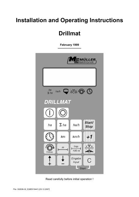
<strong>Drillmat</strong><br />
February 1999<br />
-------------------------<br />
Read carefully before initial operation !
Contents<br />
1 System description.................................................................................... 3<br />
1.1 Machine distributor....................................................................................... 3<br />
1.2 Computer ..................................................................................................... 4<br />
2 <strong>Installation</strong> instructions - <strong>Drillmat</strong> ............................................................ 5<br />
2.1 Computer ..................................................................................................... 5<br />
2.2 12V plug connection to the tractor battery.....................................................5<br />
2.3 Signal distributor - machine.......................................................................... 5<br />
2.4 Sensors........................................................................................................ 5<br />
3 Safety .......................................................................................................... 7<br />
3.1 Specified implementation ............................................................................. 7<br />
3.2 Safety instructions........................................................................................ 7<br />
4 <strong>Operating</strong> instructions............................................................................... 8<br />
4.1 Initial operation............................................................................................. 8<br />
4.2 Description of the entry keys........................................................................ 8<br />
4.2.1 Setting keys +/- ............................................................................................ 8<br />
4.2.2 "Working width" key ..................................................................................... 8<br />
4.2.3 "Impulses/100m" key.................................................................................... 9<br />
4.2.4 "RPM" key ".................................................................................................. 9<br />
4.2.5 "Tram line rhythm" key............................................................................... 10<br />
4.2.6 "+1" key...................................................................................................... 11<br />
4.2.7 "Start/stop" key .......................................................................................... 11<br />
4.3 Description of the function keys ................................................................. 12<br />
4.3.1 Device on/off .............................................................................................. 12<br />
4.3.2 "Start function" ........................................................................................... 12<br />
4.3.3 "Time" key.................................................................................................. 12<br />
4.3.4 "Area" key .................................................................................................. 12<br />
4.3.5 "Total area" key.......................................................................................... 13<br />
4.3.6 "Current area output" key........................................................................... 13<br />
4.3.7 "Distance" key............................................................................................ 13<br />
4.3.8 "Speed" key ............................................................................................... 13<br />
4.4 Operation process...................................................................................... 14<br />
5 Maintenance ............................................................................................. 14<br />
5.1 Computer ................................................................................................... 14<br />
5.2 Sensors...................................................................................................... 14<br />
6 Error recovery ........................................................................................ 15<br />
6.1 The device does not switch on................................................................... 15<br />
6.1.1 The computer displays HALP 00 or HALP 88 ............................................ 15<br />
6.2 The speed is not displayed ........................................................................ 15<br />
6.3 The area is not displayed ........................................................................... 15<br />
Page - 2 - Copyright <strong>Müller</strong>-<strong>Elektronik</strong> GmbH u. Co. <strong>Installation</strong> <strong>and</strong> <strong>Operating</strong> <strong>Instructions</strong> (02/99)
333<br />
1 System description<br />
The <strong>Drillmat</strong> is used to monitor the seed drill, to establish the working data <strong>and</strong> for<br />
tram line drilling.<br />
The <strong>Drillmat</strong> essentially consists of:<br />
- The board computer (installed in the cabin of the tractor) for the entry of the required<br />
data as well as serving as a monitor. In the case of a fault, an acoustic <strong>and</strong> optical<br />
alarm is set off.<br />
- The machine distributor (installed on the frame of the <strong>Drillmat</strong>) with a connecting cable<br />
to the board computer.<br />
With wheel sensor<br />
Sensor for monitoring the drill shaft<br />
Sensor for monitoring the fan<br />
Level sensor<br />
Track marker<br />
1.1 Machine distributor<br />
Hall element<br />
Tram line L<br />
Tram line R<br />
Hall sensor<br />
Wheel<br />
Cable – 14x1.00qmm<br />
Fan<br />
Level<br />
Lg – 6.50m<br />
Capacitive sensor<br />
Drill shaft<br />
Track marker<br />
Reed contact<br />
Reed contact<br />
30pin multipoint plug<br />
Copyright <strong>Müller</strong>-<strong>Elektronik</strong> GmbH u. Co. <strong>Installation</strong> <strong>and</strong> <strong>Operating</strong> <strong>Instructions</strong> <strong>Drillmat</strong> (02/99) Page - 3 -
1.2 Computer<br />
Delivery content<br />
– ) <strong>Drillmat</strong> compter<br />
– ) Battery cable<br />
– ) Console<br />
Page - 4 - Copyright <strong>Müller</strong>-<strong>Elektronik</strong> GmbH u. Co. <strong>Installation</strong> <strong>and</strong> <strong>Operating</strong> <strong>Instructions</strong> (02/99)
2 <strong>Installation</strong> instructions – <strong>Drillmat</strong><br />
2.1 Computer<br />
The computer is to be installed together with the console within the driver’s field of<br />
visibility. The distance from the radio equipment or radio antenna should be at least<br />
1 m.<br />
2.2 12V socket connection to the tractor battery<br />
For the <strong>Drillmat</strong>’s current supply (computer <strong>and</strong> sensors) the 12V socket supplied is<br />
to be connected to the tractor battery. No second device should be connected to this<br />
12V socket. The 12V socket must be protected by a 25A safety fuse, which is to be<br />
found in the wire connector to the brown 12V wire.<br />
Wire colours<br />
brown = + 12 Volt<br />
blue = ground<br />
The battery’s negative pole must always be at ground (frame, chassis).<br />
2.3 Signal distributor machine<br />
The signal distributor <strong>and</strong> the sensors are factory installed<br />
2.4 Sensors<br />
- Wheel sensor (Hall element)<br />
With the wheel sensor the device determines the distance covered as well as the<br />
area.<br />
The tube clip <strong>and</strong> magnet are mounted on to the wheel. The red side must point towards<br />
the sensor. The sensor is to be mounted to the fixture provided at a distance<br />
of 5-10 mm. A terminal block is provided for each lead in the machine distributor.<br />
Copyright <strong>Müller</strong>-<strong>Elektronik</strong> GmbH u. Co. <strong>Installation</strong> <strong>and</strong> <strong>Operating</strong> <strong>Instructions</strong> <strong>Drillmat</strong> (02/99) Page - 5 -
- Drill shaft sensor (Reed contact)<br />
This sensor monitors the function of the drill shaft.<br />
The tube clip <strong>and</strong> magnet are mounted on to the drill shaft. The red side must point<br />
towards the sensor. The sensor must be mounted to the fixture provided at a distance<br />
of approximately 20 mm.<br />
- Level sensor (capacitive)<br />
The sensor controls the seed bin.<br />
As soon as the surface is no longer covered with grain, the sensor switches on <strong>and</strong><br />
the computer sends out an alarm.<br />
The sensor should be placed in the seed bin, so that it switches on as soon as the<br />
set amount of residue is reached. The end of the sensor should protrude 20 mm<br />
from the screw fitting.<br />
The sensitivity can be regulated at the back of the sensor. When the sensor switches<br />
on, the lamp on the sensor lights up.<br />
- Track marker (Reed contact)<br />
The sensor indicates to the computer that the track markers have switched.<br />
The sensor is to be mounted on to a static fixture opposite the switch mechanism for<br />
the track marker. The magnet is to be mounted on to the switch mechanism opposite<br />
the sensor at a distance of 20 mm. The magnet must momentarily be lead past the<br />
sensor when the track indicator switches. It’s end position should not be in front of<br />
the sensor.<br />
The tram line meter moves on one position each time the track marker switches on.<br />
- Seed drill without track marker<br />
The switch impulse is picked up when the top link is raised. The magnet <strong>and</strong> sensor<br />
should be mounted so that they approach each other in a raised position at roughly<br />
20 mm.<br />
In a working position the distance must be at least 40 mm.<br />
- Fan sensor (Hall element)<br />
Rpm monitor on the fan<br />
Both magnets are to be mounted to the fixture provided. The red side must point towards<br />
the sensor. The sensor must be mounted at a distance of 5-10 mm to the sensors<br />
Page - 6 - Copyright <strong>Müller</strong>-<strong>Elektronik</strong> GmbH u. Co. <strong>Installation</strong> <strong>and</strong> <strong>Operating</strong> <strong>Instructions</strong> (02/99)
3 Safety<br />
3.1 Specified implementation<br />
The <strong>Drillmat</strong> is specified exclusively for use in agriculture. Any application outwith<br />
this area is regarded as unspecified.<br />
The manufacturer does not accept liability for damage to persons or property resulting<br />
from unspecified use. In such cases all risks are the responsibility of the user.<br />
Specified implementation also includes adhering to the operation <strong>and</strong> maintenance<br />
conditions stipulated by the manufacturer in the operating instructions.<br />
Relevant accident prevention regulations as well as other generally recognized<br />
safety, industrial-medical <strong>and</strong> road traffic rules are to be adhered to. In addition the<br />
manufacturer accepts no liability in cases where arbitrary modifications have been<br />
made to the <strong>Drillmat</strong>.<br />
3.2 Safety instructions<br />
Before working on the electrical system or carrying out any welding operations on<br />
the tractor or on an attached implement, the battery connection must be interrupted.<br />
Copyright <strong>Müller</strong>-<strong>Elektronik</strong> GmbH u. Co. <strong>Installation</strong> <strong>and</strong> <strong>Operating</strong> <strong>Instructions</strong> <strong>Drillmat</strong> (02/99) Page - 7 -
4 <strong>Operating</strong> instructions<br />
4.1 Initial operation<br />
The device carries out a self-test when switched on. After completion the function<br />
last used before switch-off is automatically selected.<br />
In the case of an electronical fault the device displays:<br />
HALP 00 or HALP 88<br />
In this case return the device for repair.<br />
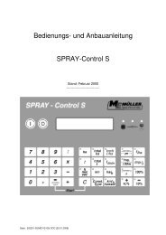
4.2 Description of the entry keys<br />
The keyboard has two colours:<br />
White keys = function keys (display the recorded data)<br />
Grey keys = entry keys (enter the machine data) <strong>and</strong> control keys<br />
4.2.1 Setting keys +/-<br />
When the + or – key is first pressed the display moves one poition in the required direction.<br />
Each time the key is pressed again, the display moves on until the key is let loose.<br />
The board computer requires following machine data in order to be able to operate<br />
at all: Impulses/100m, working width, drill shaft rpm <strong>and</strong> the tram line rhythm.<br />
4.2.2 " Working width " key<br />
This key is used to enter the actual working width<br />
- Press " working width" key<br />
- Select value using the +/- keys<br />
- Press "enter" (=) key<br />
Finally the value entered should be controlled once more by pressing the " working<br />
width" key.<br />
Page - 8 - Copyright <strong>Müller</strong>-<strong>Elektronik</strong> GmbH u. Co. <strong>Installation</strong> <strong>and</strong> <strong>Operating</strong> <strong>Instructions</strong> (02/99)
4.2.3 " Impulses/100 m" key<br />
With this key the number of impulses recorded to the computer by the wheel sensor<br />
during a journey of 100 m are entered.<br />
There are two possibilities to enter the data:<br />
1. The impulses/100m value is known<br />
- Press "impulses/100m" key<br />
- Select value using the +/- keys<br />
- Press "enter" (=) key.<br />
2. The impulses/100m value is not known<br />
- Measure out <strong>and</strong> mark a distance of 100 m on the field<br />
- Bring vehicle to the start position<br />
- Press "impulses/100m" <strong>and</strong> " C " key simultaneously<br />
- Travel a distance of 100 m<br />
- Press "enter" (=) key<br />
4.2.4 "RPM" key<br />
With the initial operation the rated rpm must be communicated to the computer.<br />
The entry is to be carried out as follows:<br />
- Start up the machine<br />
- Press the "rpm" key<br />
(current rpm will be displayed).<br />
- Press "enter" (=) key<br />
The value displayed at this moment in time is saved as the rated rpm<br />
If monitoring is to be switched off, the following entry is required:<br />
- Press the "rpm" key (display 0)<br />
- Press "enter" (=) key<br />
- Rpm monitoring is so switched off<br />
The rpm alarm is displayed by a hooting sound <strong>and</strong> a flashing of the arrow above the<br />
rpm display every second. This occurs every 5 seconds with the drill shaft alarm.<br />
Copyright <strong>Müller</strong>-<strong>Elektronik</strong> GmbH u. Co. <strong>Installation</strong> <strong>and</strong> <strong>Operating</strong> <strong>Instructions</strong> <strong>Drillmat</strong> (02/99) Page - 9 -
4.2.5 "Tram line rhythm" key<br />
Tram lines can be laid out automatically using the <strong>Drillmat</strong>. For this purpose, the corresponding<br />
shares must be closed. The working width of the seed drill <strong>and</strong> the cultivator<br />
have to be taken into account. The tram line rhythm can be calculated from<br />
these values.<br />
Working width of the cultivator<br />
Tram line rhythm = ----------------------------------------------<br />
Working width of the seed drill<br />
Example: You are using a field sprayer with a working width of 24 m <strong>and</strong> a seed drill<br />
with a working width of 6 m. In this case the tram line rhythm is 24m : 6m = 4.<br />
The calculation results in even (2, 4, 6 etc.) <strong>and</strong> uneven (1, 3, 5 etc.) rhythms. In the<br />
case of even rhythms, the tram lines are usually laid out in 2 runs. As this tends to<br />
be more inaccurate, the even rhythms can be laid out in one run (S rhythms, e.g. 4S;<br />
6S etc.) However, it has to be taken into consideration that the first run is carried out<br />
with half the working width of the seed drill <strong>and</strong> subsequently begins with position 1<br />
of the rhythm.<br />
Following rhythms are supported by the <strong>Drillmat</strong>:<br />
No. Rhythm Tram line No. Rhythm Tram line<br />
0 No rhythm 0 2-S 2s 1<br />
2 2 1, 2 4-S 4s 2<br />
3 3 2 6-S 6s 3<br />
4 4 2, 3 8-S 8s 4<br />
5 5 3 10-S 10s 5<br />
6 6 3, 4 12-S 12s 6<br />
7 7 4<br />
8 8 4, 5<br />
9 9 5<br />
10 10 5, 6<br />
11 11 6<br />
12 12 6, 7<br />
14 14 7, 8<br />
Tram line Tram line<br />
left right<br />
15 10 (20m/8m, 15/6m) beginning<br />
on the right<br />
2; 9 4; 7<br />
16 10 (20m/8m, 15/6m) beginning<br />
on the left<br />
4; 7 2; 9<br />
18 18 (18m/4m, 27/6m) be- 3; 16 7; 12<br />
ginning on the left<br />
19 10 (18m/4m, 27/6m)<br />
beginning on the right<br />
7; 12 3; 16<br />
Page - 10 - Copyright <strong>Müller</strong>-<strong>Elektronik</strong> GmbH u. Co. <strong>Installation</strong> <strong>and</strong> <strong>Operating</strong> <strong>Instructions</strong> (02/99)
To adjust the tram line rhythm press the tram line rhythm key. The correct rhythm is<br />
then set with the +/- setting keys. Finally the new rhythm is confirmed with the enter<br />
key.<br />
If the correct tram line rhythm has been adjusted <strong>and</strong> set to 1, the side of the field<br />
where work is to begin still has to be taken into account. With uneven <strong>and</strong> S<br />
rhythms, work can begin on either side of the field. With the even rhythms 4, 8 <strong>and</strong><br />
12, work must begin at the side where the closed share is, <strong>and</strong> with rhythms 6, 10<br />
<strong>and</strong> 14 on the opposite side of the field.<br />
In the case of the special rhythms, no. 15, 16, 18, 19 the side of the field where work<br />
is to begin must be determined first. “Beginning on the left” means that the side of<br />
the field when starting lies on the left h<strong>and</strong> side of the tractor in the direction of<br />
travel. Consequently, “beginning on the left” is the other way round.<br />
4.2.6 "+1" key<br />
With this key the tram lines can be switched on further manually by one step at a<br />
time.<br />
4.2.7 "Start/Stop" key<br />
With this key the automatic relaying of the tram line rhythm can be stopped <strong>and</strong> released<br />
again.<br />
When stopped, the arrow above the tram line symbol flashes !<br />
Copyright <strong>Müller</strong>-<strong>Elektronik</strong> GmbH u. Co. <strong>Installation</strong> <strong>and</strong> <strong>Operating</strong> <strong>Instructions</strong> <strong>Drillmat</strong> (02/99) Page - 11 -
4.3 Description of the function keys<br />
4.3.1 Device on/off<br />
The device is switched on by pressing the On (I) key.<br />
Switch off with the Off (0) key.<br />
Should the voltage supply drop to below 9 volt, e.g. when starting the tractor, the<br />
computer switches off automatically. It can be switched on again by pressing the On<br />
key.<br />
4.3.2 "Start function"<br />
The start function is released by pressing the "=" <strong>and</strong> "C" keys simultaneously. That<br />
means that the memory for the area, time <strong>and</strong> distance is set to 0. The time is restarted<br />
automatically by pressing this key. This function is to be carried out at the<br />
beginning of each operation.<br />
4.3.3 "Time" key<br />
The operating time since carrying out the “start function” (see 4.3.2) is displayed by<br />
pressing this key. If the tractor is switched off <strong>and</strong> the computer voltage-free, the<br />
time data entry is stopped. It restarts once the device is switched on again. The<br />
clock can also be stopped during operation. After the “time” key has been pressed, it<br />
can be pressed once again to stop the clock. To restart it, the “time” key has to be<br />
pressed yet again.<br />
4.3.4 "Area" key<br />
The area covered since carrying out the “start function” (see 4.3.2) is displayed by<br />
pressing this key. Measurement is interrupted as soon as the computer stops receiving<br />
wheel impulses.<br />
Page - 12 - Copyright <strong>Müller</strong>-<strong>Elektronik</strong> GmbH u. Co. <strong>Installation</strong> <strong>and</strong> <strong>Operating</strong> <strong>Instructions</strong> (02/99)
4.3.5 "Total area" key<br />
With this key the total area for a whole season can be determined. The memory is<br />
set to 0 at the beginning of the season by pressing the “total area” <strong>and</strong> “C” keys simultaneously.<br />
4.3.6 "Current area output" key<br />
With this key the current area output is displayed in ha/h.<br />
4.3.7 "Distance" key<br />
The distance covered since carrying out the “start function” (see 4.3.2) is displayed<br />
by pressing this key.<br />
4.3.8 "Speed"<br />
When this key is pressed the current speed travelled is displayed.<br />
Copyright <strong>Müller</strong>-<strong>Elektronik</strong> GmbH u. Co. <strong>Installation</strong> <strong>and</strong> <strong>Operating</strong> <strong>Instructions</strong> <strong>Drillmat</strong> (02/99) Page - 13 -
4.4 Operation process<br />
Once the machine data have been entered, the following steps have to be carried<br />
out before beginning operation. The track marker at the beginning of the field is to be<br />
operated so that the right side is lowered.<br />
Subsequently only the start function has to be carried out (see 4.3.2).<br />
After that, each time the end of the field is reached <strong>and</strong> the track marker switched,<br />
tram line drilling is continued automatically. Even when the computer is switched off<br />
temporarily, the last position is stored. When the computer is switched on again, the<br />
last setting is available once more. Drilling can begin again immediately.<br />
During the operation process the area, total area, operating time, distance are determined<br />
<strong>and</strong> the speed <strong>and</strong> output displayed.<br />
5 Maintenance<br />
5.1 Computer<br />
The computer is maintenance-free. During the winter it should be stored at room<br />
temperature.<br />
5.2 Sensors<br />
The sensors are maintenance-free<br />
Page - 14 - Copyright <strong>Müller</strong>-<strong>Elektronik</strong> GmbH u. Co. <strong>Installation</strong> <strong>and</strong> <strong>Operating</strong> <strong>Instructions</strong> (02/99)
6 Error recovery<br />
When trouble shooting keep to the intended sequence!<br />
Error Cause Measures<br />
6.1 The device does not<br />
switch on<br />
6.1.1 The computer displays<br />
HALP 00 or<br />
HALP 88<br />
6.2 Speed is not displayed<br />
6.3 The area is not displayed<br />
Polarity reversal of the voltage<br />
supply<br />
Check polarity<br />
Voltage supply interrupted Check battery connection<br />
cable; control battery clamps<br />
<strong>and</strong> fuse<br />
Total failure Send in device<br />
Memory error Send in device<br />
Impulses/100m not entered Enter number of Impulses/100m<br />
(see 4.2.3.)<br />
The wheel sensor is not<br />
sending any impulses to the<br />
computer, the ring in the<br />
display is not flashing during<br />
the journey.<br />
Adjust the distance of the<br />
wheel sensor to the magnet<br />
to 5-10mm.<br />
The red side of the magnet<br />
must point towards the sensor.<br />
Secure magnet with a nonmagnetic<br />
screw.<br />
Connect cable in the distributor<br />
correctly<br />
green = gn = signal<br />
brown = br = + 12 volts<br />
white = ws = 0 volt<br />
Sensor is defective, replace<br />
Computer is defective, replace<br />
Distributor is defective, replace<br />
Working width not entered Enter working width<br />
(see 4.2.2.)<br />
Copyright <strong>Müller</strong>-<strong>Elektronik</strong> GmbH u. Co. <strong>Installation</strong> <strong>and</strong> <strong>Operating</strong> <strong>Instructions</strong> <strong>Drillmat</strong> (02/99) Page - 15 -