CPUM - Zeefax Condition Monitoring
CPUM - Zeefax Condition Monitoring
CPUM - Zeefax Condition Monitoring

Create successful ePaper yourself
Turn your PDF publications into a flip-book with our unique Google optimized e-Paper software.
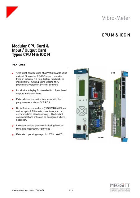
CPU M & IOC N<br />
Modular CPU Card &<br />
Input / Output Card<br />
Types CPU M & IOC N<br />
FEATURES<br />
<br />
<br />
<br />
‘One-Shot’ configuration of all VM600 cards using<br />
a direct Ethernet or RS-232 serial connection<br />
from an external PC (e.g. laptop, notebook, or<br />
industrial PC) running Vibro-Meter's MPS<br />
(Machinery Protection System) software<br />
Local micro-display for visualisation of monitored<br />
outputs and alarm limits<br />
External communication interfaces with third<br />
party devices such as DCS/PCS<br />
IOC N<br />
<br />
<br />
<br />
Up to 3 serial connections (RS232/422/485), as<br />
well as up to 2 Ethernet connections, can be<br />
accommodated simultaneously. 'Redundant'<br />
communications links can be configured where<br />
necessary<br />
Industry standard protocols including Modbus<br />
RTU‚ and Modbus/TCP provided<br />
Extended operating range of -20°C to +60°C<br />
CPU M<br />
First draft<br />
© Vibro-Meter SA / 268-031 / 04.06 / E 1 / 4
Modular CPU Card & Input / Output Card<br />
CPU M & IOC N<br />
DESCRIPTION<br />
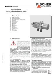
The CPU M is a modular Central Processing Unit<br />
(CPU) card intended for use in Vibro-Meter's VM600<br />
series of Machinery Protection System (MPS) and<br />
<strong>Condition</strong> <strong>Monitoring</strong> System (CMS) racks.<br />
Depending on the system requirements, the CPU M<br />
may be used alone in the rack (installed in the front<br />
card cage) or in conjunction with the corresponding<br />
IOC N Input / Output Card (installed in slot 0 of the<br />
rear card cage, directly behind the CPU M).<br />
The modular, highly versatile design of the CPU M<br />
means that all rack configuration, display and<br />
communications interfacing can be performed from a<br />
single card.<br />
The CPU M consists of a base carrier card having two<br />
PC/104 type slots. One of a range of PC/104 modules<br />
can be installed in each slot. In the standard<br />
configuration, a single PC/104 type CPU module is<br />
fitted. This provides an RS-232 connection via a DB9<br />
connector, and an Ethernet network connection via an<br />
RJ45 connector on the front panel, or alternatively, via<br />
the relevant ports on the IOC N, if installed.<br />
The IOC N is a network communications card which<br />
includes two pairs of RJ11 connectors (labelled A and<br />
B) for configuring multi-drop RS-485 networks of<br />
CPU M SPECIFICATIONS<br />
CARRIER BOARD<br />
Electrical<br />
Supply voltage<br />
RS 485 isolation<br />
Power consumption<br />
Physical<br />
Height<br />
Width<br />
Depth<br />
Weight<br />
Environmental<br />
Operating<br />
• Temperature<br />
• Humidity<br />
Storage<br />
• Temperature<br />
• Humidity<br />
VM600 racks, and another RJ45 connector for a<br />
redundant Ethernet connection. These extra<br />
connectors may be used if the optional Ethernet and<br />
RS-485 (RS-422) PC/104 modules have been<br />
installed on the CPU M.<br />
The CPU M front panel features an LCD display that<br />
shows the level of a selected monitored output in bargraph<br />
and digital form. The Alert and Danger levels<br />
are indicated on the bar-graph. The signal<br />
identification (slot and output number) is shown at the<br />
top of the display. The SLOT and OUT (output) keys<br />
on the front panel are used to select which signal to<br />
display.<br />
Coloured LEDs on the front panel indicate the OK,<br />
Alert (A) and Danger (D) status for the currently<br />
selected signal (these are coloured green, yellow and<br />
red, respectively). When Slot 0 is selected, the LEDs<br />
indicate the status of the whole rack. When the<br />
CPU M card is functioning correctly, the green DIAG<br />
(diagnostic) LED is lit.<br />
An ALARM RESET button on the front panel resets<br />
all latched alarms (and associated relays) for the<br />
entire rack.<br />
First draft<br />
: 5 V DC ± 5%<br />
: 500 V DC<br />
: < 10 W<br />
: 6U (262 mm)<br />
: 40 mm<br />
: 187 mm<br />
: 0.4 kg<br />
: -20°C to +60°C<br />
: 0 to 90% non-condensing<br />
: -20°C to +85°C<br />
: 0 to 90% non-condensing<br />
© Vibro-Meter SA / 268-031 / 04.06 / E 2 / 4
Modular CPU Card & Input / Output Card<br />
CPU M & IOC N<br />
CPU MODULE (always installed)<br />
Type<br />
Processor speed<br />
Memory<br />
Dimensions<br />
Operating temperature<br />
Power supply<br />
Operating system<br />
Communication ports<br />
• RS232/RS422/RS485<br />
• Ethernet<br />
: MSM586SEN or equivalent<br />
: 133 MHz<br />
: 128MB DRAM<br />
: 96 x 90 x 20 mm<br />
: -20°C to +60°C<br />
: +5 V DC , 100 V DC<br />
Dimensions<br />
: 96 x 90 x 20 mm<br />
Operating temperature<br />
: -20°C to +60°C<br />
Power supply<br />
: +5 V DC , 220 mA<br />
IOC N SPECIFICATIONS<br />
First draft<br />
Electrical<br />
Supply voltage<br />
Power consumption<br />
Physical<br />
Height<br />
Width<br />
Depth<br />
Weight<br />
: 5 V DC ± 5%<br />
: < 2 W<br />
: 6U (262 mm)<br />
: 20 mm<br />
: 125 mm<br />
: 0.25 kg<br />
© Vibro-Meter SA / 268-031 / 04.06 / E 3 / 4
Modular CPU Card & Input / Output Card<br />
CPU M & IOC N<br />
Communication ports<br />
Ethernet<br />
Serial<br />
Environmental<br />
Operating<br />
• Temperature<br />
• Humidity<br />
Storage<br />
• Temperature<br />
• Humidity<br />
: 2 RJ45 connectors; 10 Base-T.<br />
: 5 RJ11 connectors (RS-232 or RS-485); ‘RS’, ‘A’ (x2),<br />
‘B’ (x2).<br />
: -20°C to +60°C<br />
: 0 to 90% non-condensing<br />
: -20°C to +85°C<br />
: 0 to 90% non-condensing<br />
ORDERING INFORMATION<br />
To order please specify :<br />
Type Designation Ordering Number<br />
CPU M Modular CPU Card<br />
- Including carrier card and PC/104 CPU module (with integral Ethernet 200-595-SSS-1Hh<br />
controller)<br />
- Including carrier card, PC/104 CPU and additional Ethernet module 200-595-SSS-3Hh<br />
- Including carrier card, PC/104 CPU and additional Serial Communications 200-595-SSS-4Hh<br />
module<br />
- All other configurations On request<br />
IOC N Input / Output Card for CPU M<br />
- Standard version 200-566-000-1Hh<br />
- Separate circuits in accordance with IEC/CEI 60255-5 standard 200-566-000-2Hh<br />
Note : “SSS” represents the firmware (embedded software) version and “Hh” the hardware version. “H” increments for<br />
major modifications that can affect product interchangeability. “h” increments for minor modifications that have no effect<br />
on interchangeability.<br />
First draft<br />
In this publication, a dot (.) is used as the decimal separator and thousands are separated by spaces. Example : 12 345.678 90. Although care has been<br />
taken to assure the accuracy of the data presented in this publication, we do not assume liability for errors or omissions. We reserve the right to alter any<br />
part of this publication without prior notice.<br />
Sales offices Your local agent Head office<br />
Vibro-Meter has offices in more than 30<br />
countries. For a complete list, please visit<br />
our website.<br />
Vibro-Meter SA<br />
Rte de Moncor 4<br />
P.O. Box<br />
CH-1701 Fribourg<br />
Switzerland<br />
Tel: +41 26 407 11 11<br />
Fax: +41 26 407 13 01<br />
www.vibro-meter.com<br />
© Vibro-Meter SA / 268-031 / 04.06 / E 4 / 4