ADVANCE ZD manual - Defi
ADVANCE ZD manual - Defi
ADVANCE ZD manual - Defi

You also want an ePaper? Increase the reach of your titles
YUMPU automatically turns print PDFs into web optimized ePapers that Google loves.
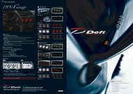
デフィーリンクメーターアドバンスズィーディー 取 扱 説 明 書<br />
<strong>Defi</strong>-Link Meter <strong>ADVANCE</strong> <strong>ZD</strong> Operation Manual<br />
DF09701<br />
日 本 国 内 でご 購 入 の 場 合 は 2 ページから 52 ページをお 読 みください。<br />
このたびは、 当 社 製 品 をお 買 い 上 げいただきまして、 誠 にありがとうご<br />
ざいます。お 客 様 ・ 取 付 業 者 様 ともに、ご 使 用 の 前 に 本 書 を 全 て 必 ずお 読<br />
みいただき、 取 付 後 も 常 にお 手 元 に 保 管 し、 正 しいお 取 り 扱 い 方 法 でご 愛<br />
用 いただけますようお 願 い 申 し 上 げます。<br />
なお、 本 品 の 装 着 に 関 する 事 故 や 弊 害 につきましては、いかなる 場 合 に<br />
おいても、 当 社 は 一 切 責 任 を 負 いかねますので、あらかじめご 了 承 いただ<br />
けますようお 願 い 申 し 上 げます。<br />
※ 英 語 の 部 分 は 国 内 では 無 効 です。<br />
【Web サイト】http://www.nippon-seiki.co.jp/defi/<br />
【 電 話 番 号 】(03)3835-3639<br />
【 受 付 時 間 】10:00 ~ 12:00、13:00 ~ 17:00( 土 ・ 日 、 祭 日 、 当 社 休 日 を 除 く 平 日 )<br />
English section is from P.53 to P.107.<br />
Thank you very much for purchasing our product. Before installing and<br />
using the product, please read this <strong>manual</strong> thoroughly. All sections are for<br />
customers and installation personnels. After installation, please keep this<br />
<strong>manual</strong> for future reference.<br />
<strong>Defi</strong> will not be held responsible for accidents or damages related to<br />
installation of this product.<br />
※ Japanese section is effective only in Japan.<br />
【Web site】http://www.defi-shop.com/
もくじ Contents<br />
もくじ Contents・ ・・・・・・・・・・・・・・・・・・ 1<br />
1 安 全 ・ 取 り 扱 いに 関 するご 注 意 【 必 ずお 読 みください】・ ・2<br />
2 特 長 ・・・・・・・・・・・・・・・・・・・・・・・・ 7<br />
3ラインナップ・・・・・・・・・・・・・・・・・・・・ 8<br />
4 仕 様 ・・・・・・・・・・・・・・・・・・・・・・・・ 9<br />
5 構 成 部 品 ・・・・・・・・・・・・・・・・・・・・・・ 10<br />
6 各 部 名 称 ・ 寸 法 (mm)・ ・・・・・・・・・・・・・・・ 11<br />
7 取 付 方 法 ・・・・・・・・・・・・・・・・・・・・・・ 13<br />
8 使 用 方 法 ・ ・・・・・・・・・・・・・・・・・・・・・ 16<br />
9トラブルシューティング・・・・・・・・・・・・・・・ 47<br />
補 修 パーツ・・・・・・・・・・・・・・・・・・・・・ 49<br />
保 守 ・ 点 検 ・ 保 証 ・アフターサービス・・・・・・・・・ 50<br />
1 Safety Warning 【Please read carefully.】・ ・・・・・・ 53<br />
2 Product Features・ ・・・・・・・・・・・・・・・・・ 59<br />
3 List of Products / Optional Parts・ ・・・・・・・・・・ 60<br />
4 Specification・ ・・・・・・・・・・・・・・・・・・・ 61<br />
5 Parts list・ ・・・・・・・・・・・・・・・・・・・・・ 62<br />
6 Part names/Dimensions in mm(inches)・・・・・・・・ 63<br />
7 Installation・ ・・・・・・・・・・・・・・・・・・・・ 65<br />
8 Operation・・・・・・・・・・・・・・・・・・・・・ 68<br />
本 製 品 は <strong>Defi</strong>-Link <strong>ADVANCE</strong> Control Unit(アドバンスコントロールユニット )<br />
と 一 緒 に 使 用 する 製 品 です。 本 製 品 だけでは 動 作 しません。 本 製 品<br />
をご 使 用 の 際 は 必 ず 別 売 のアドバンスコントロールユニットをご 購<br />
入 頂 き、 取 扱 説 明 書 も 合 わせてお 読 みください。<br />
1 安 全 ・ 取 り 扱 いに 関 するご 注 意 【 必 ずお 読 みください】<br />
本 製 品 は 車 両 情 報 を 表 示 する 製 品 です。 本 製 品 をお 取 り 付 けの 前 に 本 取 扱 説 明<br />
書 及 び 取 り 付 ける 車 両 のメーカーが 発 行 している 整 備 解 説 書 、 配 線 図 に 示 され<br />
ている 内 容 や 安 全 に 関 する 注 意 事 項 をよくお 読 みいただき、 十 分 に 理 解 された<br />
上 でお 取 り 付 けいただけますようお 願 い 申 し 上 げます。また、 本 製 品 ( 及 び 本<br />
製 品 の 取 り 付 けられている 車 ) を 他 の 人 に 貸 し 出 したり 譲 渡 する 場 合 は、 取 扱<br />
説 明 書 と 保 証 書 を 必 ずお 渡 しください。<br />
なお、エンジンコンピュータ 配 線 図 は 当 社 Web サイトに 掲 載 しておりますの<br />
で、ご 確 認 ください。<br />
本 書 では、 取 り 扱 いを 誤 った 場 合 などの 危 険 の 程 度 を「 危 険 」「 警 告 」「 注 意 」<br />
の 3 つのレベルで 分 類 しています。また、 本 製 品 を 安 全 に 正 しくお 使 いいた<br />
だくために 必 ず 行 っていただきたい 事 項 と、 守 っていただきたい 事 項 を「 確 認 」<br />
として 分 類 しています。 内 容 をよくお 読 みいただき、 十 分 に 理 解 された 上 でお<br />
取 り 付 けください。<br />
危 険<br />
取 り 扱 いを 誤 った 場 合 、 死 亡 、 又 は 重 傷 を 負 うことがあり、<br />
かつその 切 迫 度 合 いが 高 いことが 想 定 される 場 合 。<br />
警 告<br />
取 り 扱 いを 誤 った 場 合 、 死 亡 、 又 は 重 傷 を 負 う 可 能 性 が 想 定<br />
される 場 合 。<br />
注 意<br />
取 り 扱 いを 誤 った 場 合 、 傷 害 を 負 う 危 険 が 想 定 される 場 合 、<br />
または 物 的 損 害 の 発 生 が 想 定 される 場 合 。<br />
確 認<br />
「 必 ず 行 っていただきたい 事 」、「 必 ず 守 っていただきたい 事 」<br />
を 示 しています。<br />
注 意 内 容 の 性 質 表 示<br />
9 Troubleshooting・・・・・・・・・・・・・・・・・・ 99<br />
Repair parts・・・・・・・・・・・・・・・・・・・・・ 101<br />
Maintenance & Check/Warranty & Servicing・ ・・・・・ 102<br />
禁 止<br />
強 制<br />
注 意 ( 警 告 を 含 む ) をしなければならない 記 号 です。<br />
は、 行 為 を 禁 止 する 記 号 です。( 絶 対 にしてはいけない 事 です。)<br />
は、 行 為 を 指 示 する 記 号 です。( 必 ず 行 って 頂 くことです。)<br />
1 2
This product functions with <strong>Defi</strong>-Link <strong>ADVANCE</strong> Control unit. This<br />
product alone does not function. Please refer to <strong>Defi</strong>-Link <strong>ADVANCE</strong><br />
Control unit operation <strong>manual</strong> as well.<br />
1 Safety Warning 【Please read carefully.】<br />
This product is an additional product for providing information to automobile<br />
users about engine conditions and other important factors. When installing<br />
and operating this product, be sure to read the cautionary items of this operation<br />
<strong>manual</strong> as well as those given in the operation <strong>manual</strong> for the vehicle in<br />
which this product will be installed. Please obtain a full understanding of the<br />
cautionary items and use the product accordingly.<br />
In the event that this product (or the vehicle in which it is installed) is lent to or<br />
transferred to another person, please be sure this operation <strong>manual</strong> and warranty<br />
card accompany the product.<br />
In this <strong>manual</strong>, the degree of hazard arising from actions such as improper<br />
operation is separated into the 3 levels "Danger," "Warning," and "Caution."<br />
In addition, instructions that must be followed for safe and proper use of this<br />
product as well as practices that must be maintained are marked with a "Confirmation"<br />
heading. Please read and become familiar with these sections.<br />
Indicates the imminent dangerous situation of death or serious<br />
injury if the product is mishandled<br />
Danger<br />
Indicates the possibility of death or serious injury if the product<br />
is mishandled.<br />
Warning<br />
Indicates a conceivable source of personal injury or damage<br />
Caution<br />
to equipment if the product is improperly operated.<br />
Indicates an instruction that must be performed or practice<br />
Confirmation<br />
that must be maintained.<br />
Properties for safety warning<br />
Indicates attention needs to be paid. (Including warnings)<br />
Prohibited Indicates restricted actions. (PROHIBITED actions)<br />
Must Indicates actions that need to be carried out. (MUST actions)<br />
■ Before handling (for installation personnel)<br />
Danger<br />
Ensure that the vehicle will remain stationary and turn off the engine before<br />
installing this product. Failure to do so could result in a fire, and could make<br />
the vehicle move during installation.<br />
Remove the key from the ignition and disconnect the negative (-) battery<br />
terminal prior to installation of this product. Failure to do so could result in<br />
a fire caused by an electrical short circuit.<br />
Take care not to install this product in a way that interferes with safety equipment<br />
such as seat belts and air bag systems or vehicle operation equipment<br />
such as engine controls, steering wheel and brake systems. Interference<br />
with normal operation of the vehicle can result in an accident or fire.<br />
Solder or use a solderless connector for wiring connections and make sure<br />
connections are insulated. In areas where there could be tension or sudden<br />
impacts on the wiring, safeguard the wiring with corrugated tubing or<br />
other shock absorbent material. Accidental shorts can cause fires.<br />
While wiring power supply wire, to avoid the risk of electrical shock or fire,<br />
be sure to confirm that there is no disconnection or breakage of wire. Poor<br />
connection can result in short-circuit, electrical shock, fire, or other hazards.<br />
The ignition-switched +12V(IGN) line must be connected to the vehicle's<br />
ignition-switched wire with a fuse of 30A or less. High-capacity fuse(more<br />
than 30A) will not blowout even with an abnormal current flow and may<br />
cause fire.<br />
Discontinue use of this product if a blowout of the fuse has occurred. Continued<br />
use while the condition exists could result in an accident, fire, or<br />
damage to the vehicle.<br />
Use the tube fuse of regulated capacity when the fuse of the power wire is<br />
changed. Using a fuse that exceeds regulated capacity may cause fire.<br />
Do not install the product in wet places. It may result in a fire caused by an<br />
electrical short circuit.<br />
Discontinue use of this product if the product doesn't operate or operates<br />
improperly. Continued use while the condition exists could result in an accident<br />
or damage.<br />
53 54
Warning<br />
Carefully consider the installation location and driver's operation of the<br />
product before installation. Do not install the product where it interrupts<br />
driving and the safety deices of vehicle such as air bags. Be sure not to<br />
install the unit where it could fall. Improper installation or operation could<br />
cause the product to fall and damage the vehicle or cause serious danger<br />
by impeding driving.<br />
Do not disassemble or modify this product. Such actions can<br />
not only damage or destroy the product but also will void the Disassemble/<br />
warranty.<br />
Modify<br />
Do not perform installation of this product immediately after the engine has<br />
been switched off. The engine and exhaust system are extremely hot at this<br />
time and can cause burns if touched.<br />
Ensure that the wiring of this product does not have an adverse impact on<br />
the other wiring of the vehicle. Before tapping speed or engine rev signal<br />
from the ECU, please make sure that you have connected power cables<br />
inside power supply wire properly. Then confirm that the DC Source LED<br />
is lighted with ignition on. If it is functioning normally, remove negative<br />
terminal connector from battery and go ahead with wiring procedure.<br />
Incorrect wiring may destroy your ECU, ignition system and other engine<br />
management devices.<br />
Please keep children and infants away from the installation area. Children<br />
may swallow small parts or be injured in other ways.<br />
Do not install this product in the area where safety equipment such as air<br />
bags are mounted. This may cause more injuries in the event of accident.<br />
Caution<br />
This product is designed for use on 12V vehicles. Do not install<br />
this product on vehicles with 24V systems.<br />
24V<br />
Insulate any unused wires. If any wires or connectors loosen during installation,<br />
please make sure they are correctly reattached.<br />
Do not drop any of the components of this product. It may result in damage<br />
to the product.<br />
Do not apply excessive force on switches/terminals. It may result in damage<br />
to the product.<br />
Do not use wires other than the provided wires.<br />
Do not attach wires on the body of the vehicle or engine parts as this may<br />
result in damage to the product.<br />
Install wires away from ignition and also radio signal frequency interference<br />
as this could cause the gauges to malfunction.<br />
Please set it up so that the equipment such as the wireless machines and<br />
cellular phones that emit electric waves should not touch the unit. It may<br />
result in incorrect operation.<br />
Do not place wires near the engine, exhaust pipe or turbine. It may result in<br />
damage or fusion of wires.<br />
Make sure the waterproof processing is done when diverging wires in the<br />
engine compartment.<br />
When installing the sensor, do not bend the wire near the sensor body.<br />
Wear gloves to avoid burns when soldering and cuts when installing wires,<br />
sharp edges of parts.<br />
Do not expose the unit to moisture, dust or direct sunlight, or place product<br />
directly in front of heat vents.<br />
Install sensors away from hot or wet places.<br />
When using sunshade, put sunshade between products and windshield to<br />
avoid direct sun exposure.<br />
Use a dried soft cloth for cleanup. Do not use cleaners except neutral detergent.<br />
It may damage the product.<br />
Do not pull the wires out of connectors forcefully. The<br />
connectors may be broken and the wires may be cut.<br />
When pulling out the wires, press the lock firmly to unclip<br />
the locks of connectors.<br />
Do not install gauges, including this product, into the passenger side or<br />
center of the dashboard. It doesn't meet vehicle safety standards.<br />
Confirmation<br />
Be sure to follow all instructions in this <strong>manual</strong> to ensure safe installation<br />
and operation of the product.<br />
55 56
When the negative (-) battery terminal is disconnected, equipment such<br />
as clocks and audio components having internal memory may lose their<br />
memory data. Follow the operation <strong>manual</strong> of each component to reset<br />
data after installation of this product.<br />
After installation is complete, return this operation <strong>manual</strong>, warranty card,<br />
and the package along with the warranty to the customer .<br />
Please confirm with the maintenance book that the car manufacturer issued<br />
when installing and detaching genuine parts.<br />
Before tapping wires, check the voltage of the existing wire. After tapping<br />
the wire, check the voltage of the tapped wire again to confirm whether<br />
you have tapped into the proper place.<br />
If car navigation system or car television is installed in vehicle, gauges and<br />
wires of this product need to be kept as far away as possible from the wiring<br />
and installing positions of car navigation system or car television. Failure to<br />
do so may result in interference of television display(VHF).<br />
On no event will Nippon Seiki Co., Ltd. be liable to you for any damages or<br />
losses of genuine parts for your vehicle while installing.<br />
■ About Installation and Operation (for customer and installation personnel)<br />
Warning<br />
Please have this product installed by store professional or dealer where it<br />
was purchased. Installation by the customer will void the warranty.<br />
Do not disassemble or modify this product. Such actions will<br />
not only void the warranty but also damage or destroy the<br />
product.<br />
Disassemble/<br />
Modify<br />
In order to ensure safe driving, check the information on the gauge only for<br />
a short period of time. Looking at the display for a long period of time could<br />
distract attention from the road and result in an accident.<br />
Discontinue use of this product if the gauge doesn't operate, water gets<br />
into the unit, or smoke or a strange odor comes from the unit. If such a condition<br />
occurs, contact the store or installation personnel as soon as possible.<br />
Continued use while the condition exists could result in an accident or fire.<br />
Do not operate while driving.<br />
Fix the switch unit and other parts tightly to the vehicle to avoid children's<br />
accidentally swallowing them.<br />
Do not use the TIME ATTACK function in open roads. It is only for closed<br />
courses.<br />
Caution<br />
On no event will Nippon Seiki Co., Ltd. be liable for any damages arising out<br />
of the use or inability to use the product, even if Nippon Seiki Co., Ltd. has<br />
been advised of the possibility of such damage.<br />
Do not pull the wires out of connectors forcefully. The connectors may be<br />
broken and the wires may be cut. When pulling out the wires, press the<br />
lock firmly to unclip the locks of connectors.<br />
Confirmation<br />
This product cannot be linked to the previous version of <strong>Defi</strong>-Link System.<br />
The information displayed on this product are for reference purposes only.<br />
Please drive according to the indication of vehicle's originally equipped instruments.<br />
This product can be used only on 1, 2, 3, 4, 5, 6, and 8 cylinder vehicles with<br />
4 cycle engine. This product cannot be used on diesel vehicles.<br />
Please check the installed product regularly. Durability might deteriorate<br />
according to use conditions, etc.<br />
57 58
2 Product Features<br />
The display is high-brightness and high-definition OLED made by Nippon Seiki.<br />
The advanced system (interactive communication) is implemented.<br />
By connecting this product to the <strong>ADVANCE</strong> system, the illumination of<br />
<strong>ADVANCE</strong> BF and CR gauges is controlled automatically.<br />
Time of 0-100km/h(60MPH) and 0-200km/h(100MPH) can be measured.<br />
Warm-up mode is equipped to guard engine.<br />
Opening and ending mode can be selected from 2 variations.<br />
Self-diagnosis system detects a disconnection of wire, short circuit and<br />
communication error, and indicates the error condition.<br />
Warning value can be set. The display is highlighted and buzzer sounds<br />
during warning. (The buzzer can be set ON/OFF.)<br />
Data obtained during driving (including peak value and warning value) can<br />
be stored up to 3 minutes, and the data can be replayed after driving.<br />
When both fuel pressure sensor and turbo sensor installed, differential pressure<br />
can be displayed.<br />
Display pattern can be selected from 4 display modes. (Maximum 6 items<br />
can be displayed all together on one GAUGE display.)<br />
3 List of Products / Optional Parts<br />
Product name<br />
<strong>Defi</strong>-Link Meter <strong>ADVANCE</strong> <strong>ZD</strong><br />
Product name<br />
<strong>Defi</strong>-Link <strong>ADVANCE</strong> Control Unit<br />
Product No.<br />
DF09701<br />
Product No.<br />
DF07703<br />
<strong>Defi</strong>-Link <strong>ADVANCE</strong> Control Unit is necessary to operate <strong>ADVANCE</strong> <strong>ZD</strong>.<br />
One <strong>ADVANCE</strong> Control Unit can control up to 7 gauges and <strong>ZD</strong>s all-in.<br />
■ Optional parts<br />
AD = For <strong>ADVANCE</strong> System exclusive use<br />
Part name<br />
Part No.<br />
OP1 AD Oil press sensor set PDF08106SS<br />
OP2 AD Fuel press sensor set PDF08205SS<br />
OP3 AD Oil temp sensor set PDF08305SS<br />
OP4 AD Water temp sensor set PDF08405SS<br />
OP5 AD Ext. temp sensor set PDF08505SS<br />
STREET display<br />
TIME ATTACK display<br />
GAUGE1 display<br />
GAUGE2 display<br />
The display items and the layout can be changed.<br />
Equipped with sequential indicator with 8 LEDs.<br />
Equipped with clock and alarm functions.<br />
Mounting angles are more flexible than conventional products<br />
Equipped with odometer and trip meter<br />
Oil, water, and exhaust temperatures can be displayed from 0℃ (32°F).<br />
Graphic animation plays during idling (Special mode).<br />
59 60
4 Specification<br />
Power supply voltage 10V ~ 16V DC(For 12V vehicle)<br />
<strong>ADVANCE</strong> Control<br />
unit Current consumption<br />
+B line 2A(IGN ON)<br />
5mA(IGN OFF)<br />
ILM line 800mA<br />
(Maximum value obtained when connecting 7 gauges and <strong>ZD</strong>s)<br />
Operation temperature<br />
-20 ~ +60℃ , -4 ~ +140°F(Under 80% relative humidity)<br />
range<br />
Storage temperature<br />
-30 ~ +80℃ , -22 ~ +176°F(Under 80% relative humidity)<br />
range<br />
Display range Speed 0 ~ 400km/h(0 ~ 240MPH)<br />
Tachometer<br />
0 ~ 11,000rpm<br />
OP1 Oil Pressure 0 ~ 1,000kPa(0 ~ 145PSI)<br />
OP2 Fuel Pressure 0 ~ 600kPa(0 ~ 87PSI)<br />
OP3 Oil Temperature 0 ~ 150℃ (32 ~ 302°F)<br />
OP4 Water Temperature 0 ~ 150℃ (32 ~ 302°F)<br />
OP5 Exhaust temperature 0 ~ 1,100℃ (32 ~ 2,010°F)<br />
Volt<br />
10 ~ 16V<br />
Clock<br />
12 hours display<br />
Applicable speed<br />
pulse<br />
2・4・8・16pulse(mainly for Japanese vehicles)<br />
Pulse free setting: 1,274 ~ 16,562pulse/km,<br />
2,051 ~ 26,665pulse/mile(corresponds to 2 ~ 26pulse)<br />
Applicable number<br />
1・2・3・4・5・6・8 (4cycle)<br />
of cylinders<br />
Dimensions Refer to part names and dimensions section.<br />
Weight<br />
400g, 0.9lb (including box, mounting parts, wires, and accessories)<br />
※ To display OP1 through OP5 in Display range, the sensor sets OP1 through<br />
OP5 need to be purchased separately. (Ex. To display Oil pressure, AD Oil<br />
pressure sensor set OP1 needs to be purchased separately.) However, AD-<br />
VANCE gauges are already installed, the sensor set is not necessary to be<br />
purchased separately.<br />
※ <strong>ADVANCE</strong> <strong>ZD</strong> cannot display turbo or intake manifold pressure.<br />
5 Parts list<br />
<br />
<br />
<br />
<br />
<br />
<br />
<br />
<br />
<br />
<br />
<br />
<br />
<br />
<br />
<br />
<br />
<br />
<br />
<br />
<br />
<br />
<br />
<br />
<br />
<br />
<br />
<br />
<br />
61 62
6 Part names/Dimensions in mm(inches)<br />
<br />
<br />
<br />
<br />
<br />
<br />
OLED Display<br />
<br />
<br />
<br />
<br />
<br />
<br />
<br />
<br />
<br />
<br />
■ Installation diagram<br />
<strong>ADVANCE</strong><br />
Control Unit<br />
CR<br />
BF<br />
<br />
<br />
<br />
<br />
<br />
<br />
<br />
<br />
<strong>ZD</strong><br />
<br />
<strong>ZD</strong><br />
CR<br />
BF<br />
CR<br />
■ Buttons<br />
In this <strong>manual</strong>, the SELECT button and the SET button are illustrated as follows:<br />
<br />
<br />
<br />
<br />
<br />
<br />
<br />
<br />
<br />
<br />
The meter wire can be connected to both two connectors of METER OUTPUT.<br />
Up to 7 gauges and displays in all can be connected to one control unit. (Ex. If<br />
7 gauges are connected to one line, none can be connected to the other line.<br />
If three gauges are connected to one line, up to 4 gauges can be connected to<br />
the other line.)<br />
※ Do not connect more than one gauge of the same variety. (Ex. You can NOT<br />
connect 2 turbo gauges together.) However, several <strong>ZD</strong>s can be connected.<br />
63 64
7 Installation<br />
7 -4. Installation of <strong>ZD</strong> and wiring of meter wire<br />
7 -1. Confirmation of contents.<br />
Confirm the contents. ⇒ Refer to 5 Parts list.<br />
7 -2. Installation of <strong>ADVANCE</strong> Control unit and sensors<br />
Install <strong>ADVANCE</strong> Control unit, sensors, and sensor wires by referring to the <strong>manual</strong>s.<br />
⇒ Refer to <strong>manual</strong>s of <strong>ADVANCE</strong> Control unit, gauges, and sensor sets<br />
7 -3. Wiring of speed and tachometer signal wire<br />
1. Disconnect the negative(-) battery terminal.<br />
2. Connect the green wire(SP) to SP signal of ECU.<br />
3. Connect the blue wire(TA) to TA signal of ECU. If the tachometer signal wire<br />
of <strong>ADVANCE</strong> series is already wired, connect only the green wire. (Do not<br />
use the speed and tachometer signal wire included in this product.)<br />
⇒ Refer to how to solder and how to use the solderless connectors.<br />
4. Connect the speed and tachometer signal wire to <strong>ADVANCE</strong> Control unit. (In<br />
case the wire is already connected, skip this step.)<br />
5. Connect the negative(-) battery terminal.<br />
6. Set the speed pulse, number of cylinders, and tachometer response after all<br />
the installation and wiring are done by referring operation section.<br />
■ Caution for wiring of speed and tachometer signal wires<br />
Caution<br />
If there is an unconnected wire, be sure to insulate it.<br />
1. The bolt holder and the hexagon head bolt<br />
are inserted into the slit of brace. And the<br />
knob is temporarily fastened.<br />
2. Insert convex part of the mounting bracket<br />
over the legs of the brace. And Attach the<br />
mounting bracket to the brace with the<br />
bolt, nut and washer included in the kit as<br />
shown in the figure 1.<br />
3. Cut the buffer into 30x85mm (2 pieces) and<br />
attach them to the backside of <strong>ZD</strong> (2 places)<br />
as shown in figure 2.<br />
4. Connect the meter wire to the connector<br />
on the backside of <strong>ZD</strong>.<br />
5. Insert the bolt holder of brace into the<br />
groove of <strong>ZD</strong> and then fasten the knob as<br />
shown in figure 3. If it is too tight-fitting to<br />
insert, unfasten the knob once.<br />
6. Adjust the angle and location to attach.<br />
The mounting bracket is bendable to fit on<br />
the place to attach.<br />
7. Attach double sided tape on backside of<br />
the mounting bracket (4 places) as shown<br />
in figure 4. Fix <strong>ZD</strong> on the place where you<br />
intend to attach it.<br />
8. Confirm the knob and bolts are fastened<br />
firmly and <strong>ZD</strong> is fixed firmly.<br />
9. Carry out the final confirmation according<br />
to the <strong>manual</strong> of <strong>ADVANCE</strong> Control unit.<br />
⇒ Refer to <strong>manual</strong> of <strong>ADVANCE</strong> Control unit.<br />
<br />
<br />
<br />
<br />
<br />
<br />
65 66
Confirmation<br />
Use appropriate dashboard cleaning liquids (commercially available) to<br />
clean the area where the double sided tape will be attached.<br />
If the adherence of double sided tape is not enough, use commercial tapping<br />
screws(4mm).<br />
7 -5. Setting and checking of operations<br />
Both the switch unit of <strong>ADVANCE</strong> Control Unit and the buttons on <strong>ZD</strong> are used<br />
to set up and operate. In this <strong>manual</strong>, each operation is indicated as:<br />
<strong>ADVANCE</strong> Control unit operation → CU OPR <strong>ZD</strong> operation → <strong>ZD</strong> OPR<br />
1. Turn the ignition ON. Confirm DC SOURCE LED of <strong>ADVANCE</strong> Control unit<br />
lights up.<br />
⇒ Refer to <strong>manual</strong> of <strong>ADVANCE</strong> Control unit.<br />
2. Confirm the opening mode is performed (and then STREET display mode is<br />
displayed).<br />
⇒ Refer to 8 -5. Opening mode, 8 -6-2. Real mode<br />
3. Confirm short-circuit (SHORT) or disconnected (OPEN) errors are not displayed.<br />
⇒ Refer to 8 -8. Error display<br />
If an error is displayed<br />
→ Turn the ignition off immediately, and then confirm the wiring of the<br />
sensor and the sensor wire.<br />
4. Set up the speed pulse, number of cylinders, and tachometer response in<br />
the system setup mode.<br />
⇒ Refer to 8 -2. System setup mode<br />
5. Set up the items displayed and warning values.<br />
⇒ Refer to 8 -3. Display setup mode, 8 -7. Warning setup mode<br />
6. Confirm <strong>ZD</strong> functions properly.<br />
Warning<br />
Set up while the vehicle is stopped.<br />
8 Operation 8 -1. State transition diagram<br />
<strong>Defi</strong>-Link <strong>ADVANCE</strong> System is composed as following diagram:<br />
<br />
<br />
<br />
<br />
<br />
<br />
<br />
<br />
<br />
<br />
<br />
<br />
<br />
<br />
<br />
<br />
<br />
<br />
<br />
<br />
<br />
<br />
<br />
<br />
<br />
<br />
<br />
<br />
<br />
<br />
<br />
<br />
<br />
<br />
<br />
<br />
<br />
<br />
<br />
<br />
<br />
<br />
<br />
<br />
<br />
<br />
<br />
<br />
<br />
<br />
<br />
<br />
<br />
<br />
<br />
<br />
<br />
67 68
8 -2. System setup mode (S1)<br />
Set the speed pulse, number of cylinders, tachometer response, and so on.<br />
If <strong>ADVANCE</strong> tachometer is installed and number of cylinders and tachometer<br />
response are already set, the settings are applied to <strong>ZD</strong>.<br />
Caution<br />
Make sure all the setting is done correctly. The product doesn’t operate properly.<br />
Set up while the vehicle is stopped.<br />
CU OPR (slide switch position: )<br />
1. Set the slide switch to .<br />
2. By pressing button long,<br />
the display shifts to system setup mode,<br />
and SYSTEM SETUP menu is displayed. UNIT<br />
setup is highlighted at the start.<br />
3. Choose the item to change by pressing<br />
or button. By pressing<br />
the button, the item to<br />
setup is highlighted.<br />
4. Change the setting properly by pressing or button.<br />
By pressing button, the setting is framed and set.<br />
5. Return the slide switch to or after all the settings are<br />
done.<br />
Setting items On the screen Default<br />
Units setting UNIT km/h ・kPa・℃<br />
Speed pulses setting SPEED PULSES 4<br />
Number of cylinders setting ENGINE CYLINDERS 4<br />
Tachometer response setting TACHO RESPONSE 1:HIGH<br />
Dimmer setting DIMMER Manual<br />
Special display setting SPECIAL MODE ON<br />
Warm-up setting WARM UP MODE OFF<br />
Clock setting CLOCK 1:00(+B ON)<br />
8 -2-1. Units setting [UNIT]<br />
Choose [UNIT] by pressing or button, and then press<br />
button. Choose [km/h・kPa・℃ ] or [MPH・PSI・°F] by<br />
pressing or button, and then press <br />
button.<br />
8 -2-2. Speed pulse setting [SPEED PULSES]<br />
Choose [SPEED PULSES] by pressing or button, and<br />
then press button. Choose proper speed pulse by pressing<br />
or button, and then press button.<br />
■ Pulse free setting<br />
1. If your vehicle is not 2, 4, 8, or 16 pulse, choose FREE and press<br />
button.<br />
2. If you set the pulse now, select NEW VALUE<br />
by pressing or <br />
button and press button.<br />
If you do not set the pulse now,<br />
select CURRENT VALUE. by pressing<br />
or button and press<br />
button.<br />
3. After NEW VALUE is selected, press<br />
button when the builtin<br />
speedometer of your vehicle indicates<br />
60km/h or 40MPH.<br />
69 70
4. The speed pulse is within the limits of setting,<br />
COMPLETED is displayed and buzzer<br />
sounds. Press button to set.<br />
When the speed pulse is NOT within the<br />
limits of setting, INCOMPLETED is displayed.<br />
Press button to return the<br />
system setup mode.<br />
※ Ask fellow passengers to set up. Do not set up at the wheel.<br />
※ It may be unable to be adapted for some models of vehicles.<br />
8 -2-3. Number of cylinders setting [ENGINE CYLINDERS]<br />
Choose [ENGINE CYLINDERS] by pressing or button,<br />
and then press button. Choose proper number of cylinders<br />
by pressing or button, and then press <br />
button.<br />
8 -2-5. Dimmer setting [DIMMER]<br />
Choose [DIMMER] by pressing or button, and then<br />
press button. Select [AUTO] or [MANUAL] by pressing<br />
or button, and then press button.<br />
If [AUTO] is selected, the brightness of display is adjusted automatically depending<br />
on the outside light. If [MANUAL] is selected, the brightness of display<br />
is fixed. AUTO level can be selected from 4 levels (3 automatic levels and<br />
constant maximum brightness level) by pressing button in<br />
real mode or record mode. (It is easy to realize the difference between 3 levels<br />
in dark place.)<br />
MANUAL level can be selected from 5 levels<br />
(one more constant maximum brightness level<br />
in nighttime) by pressing button<br />
in real mode or record mode.<br />
⇒ Refer to 8 -6-1. Refer to brightness adjustment.<br />
※ When setting the number of cylinders for<br />
a rotary engine, set it to 4 cylinders for 2<br />
rotors(setting of RX-8 is 2 cylinders), and to<br />
6 cylinders for 3 rotors.<br />
8 -2-4 Tachometer response setting [TACHO RESPONSE]<br />
Choose [TACHO RESPONSE] by pressing or button,<br />
and then press button. Choose preferred number of level by<br />
pressing or button, and then press <br />
button. Check the actual response and select your preferred level.<br />
8 -2-6. Special display setting [SPECIAL MODE]<br />
Choose [SPECIAL MODE] by pressing<br />
or button, and then<br />
press button. Select [ON] or<br />
[OFF] by pressing or <br />
button, and then press button.<br />
If [ON] is selected, a graphic animation is played after the speed signal keeps<br />
0km/h(0MPH) for more than 10 seconds.<br />
71 72
8 -2-7. Warm-up setting [WARM UP MODE]<br />
Choose [WARM UP MODE] by pressing<br />
or button, and then<br />
press button. Select [WATER<br />
TEMP] or [OIL TEMP] by pressing <br />
or button, and then press<br />
button.<br />
If you connect more than one <strong>ZD</strong><br />
※ If you additionally connect <strong>ZD</strong> which was connected to other vehicle to<br />
your vehicle, you need to set the display number first.<br />
⇒ Refer to 8 -3-8. Display number setting.<br />
If you connect more than one <strong>ZD</strong>, one of the <strong>ZD</strong>s is set as an ACTIVE display.<br />
■ The role of ACTIVE display<br />
ACTIVE display controls the brightness of all the connected displays (and<br />
gauges) by sensing the outside brightness with the dim sensor if the AUTO<br />
dimmer is on. SYSTEM SETUP menu is displayed only on the ACTIVE display.<br />
If [WATER TEMP] or [OIL TEMP] is selected, set<br />
the temperature which warming-up is done by<br />
pressing or button. If<br />
or button is pressed<br />
long, the setting value changes quickly. Then<br />
press button to set.<br />
ACTIVE display<br />
■ How to change the ACTIVE <strong>ZD</strong><br />
Non-ACTIVE display<br />
8 -2-8. Clock setting [CLOCK]<br />
Choose [CLOCK] by pressing <br />
or button, and then press<br />
button. Set the watch(hour)<br />
by pressing or button,<br />
and then press button.<br />
Set the watch(minute) by pressing <br />
or button, and then press<br />
button.<br />
CU OPR (slide switch position: )<br />
1. Set the slide switch to .<br />
2. The ACTIVE <strong>ZD</strong> is changed each time or button is<br />
pressed and [ACTIVE] is displayed in multi-display zone (Zone A5).<br />
※ [ACTIVE] is not displayed when only one <strong>ZD</strong> is connected to the <strong>ADVANCE</strong> system.<br />
⇒ Refer to 8 -4. Display item change<br />
as for multi-display zone.<br />
The settings of the following system setup menu can be changed in each <strong>ZD</strong>.<br />
8 -2-1. Units setting 8 -2-6. Special display setting/ 8 -2-7. Warm-up setting<br />
Change the ACTIVE <strong>ZD</strong> first to change the settings of 8 -2-1, 8 -2-6, and 8 -2-7<br />
if several <strong>ZD</strong>s are connected to the <strong>ADVANCE</strong> system.<br />
73 74
8 -3. Display setup mode (S2)<br />
Set the rev bar display, indicator lighting, and warning buzzer, etc.<br />
Caution<br />
Set up while the vehicle is stopped.<br />
※ Stop the special display by pressing or button once<br />
when you set up if the graphic animation of special display is being played.<br />
<strong>ZD</strong> OPR<br />
1. By pressing and buttons at the same time, the display<br />
shifts to display setup mode, and display setup menu is displayed. REV<br />
BAR SCALE setup is highlighted at the start.<br />
2. Choose the item to change by pressing button. By pressing<br />
button, the setting is changed.<br />
3. After all the display settings are done, press and <br />
buttons at the same time to return to real mode.<br />
Setting items On the screen Default<br />
REV BAR scale range setting REV BAR RANGE 3000RPM<br />
REV BAR maximum scale value setting REV BAR MAX SCALE 8000RPM<br />
Sequential indicator lighting pattern setting SEQ. IND. PATTERN SINGLE<br />
Sequential indicator lighting step setting SEQ. IND. STEP 200RPM<br />
Oil pressure warning limit setting OIL PRESS WARNING LIMIT 3000RPM<br />
Warning buzzer setting DISPLAY WARNING BUZZER ON<br />
Alarm setting ALARM OFF<br />
Display number setting DISPLAY NO. No.1<br />
8 -3-1. REV BAR scale range setting [REV BAR RANGE]<br />
The scale range of rev bar (the difference between maximum and minimum<br />
scale values) in digital display can be set.<br />
Choose [REV BAR RANGE] by pressing<br />
button. Select [3000RPM] or<br />
[4000RPM] by pressing button.<br />
8 -3-2. REV BAR maximum scale value setting [REV BAR MAX SCALE]<br />
The maximum scale value in digital display can be set.<br />
Choose [REV BAR MAX SCALE] by pressing<br />
button. Each time button<br />
is pressed, the value increases by 500RPM.<br />
When the setting of REV BAR RANGE is 3000RPM, the lower limit of REV BAR<br />
MAX SCALE is 3000RPM. When the setting of REV BAR RANGE is 4000RPM, the<br />
lower limit of REV BAR MAX SCALE is 4000RPM.<br />
Setting range:<br />
REV BAR RANGE: 3000RPM<br />
REV BAR MAX SCALE: 8000RPM<br />
Display range: 5000RPM to 8000RPM<br />
REV BAR RANGE: 4000RPM<br />
REV BAR MAX SCALE: 8000RPM<br />
Display range: 4000RPM to 8000RPM<br />
8 -3-3. Sequential indicator lighting pattern setting [SEQ. IND. PATTERN]<br />
Choose [SEQ. IND. PATTERN] by pressing button. Select [SINGLE]<br />
or [DUAL] by pressing button.<br />
⇒ Refer to 8 -9.<br />
Sequential<br />
indicator<br />
8 -3-4. Sequential indicator lighting step setting [SEQ. IND. STEP]<br />
Choose [SEQ. IND. STEP] by pressing<br />
button. Select preferred step by<br />
pressing button.<br />
Lighting step:<br />
⇒ Refer to 8 -9. Sequential indicator<br />
75 76
8 -3-5. Oil pressure warning limit setting [OIL PRESS WARNING LIMIT]<br />
The warning function of oil pressure is put out when engine revolutions are<br />
under the set value. ※ This setting is reflected only to the <strong>ZD</strong> which is changed.<br />
Choose [OIL PRESS WARNING LIMIT] by pressing<br />
button. Each time <br />
button is pressed, the value increases by<br />
500RPM.<br />
Setting range:<br />
To set the alarm ON, select [ON] by pressing<br />
button and then press <br />
button.<br />
Set the watch(hour) by pressing <br />
button and then press button. If<br />
button is pressed long, the digit<br />
changes quickly.<br />
8 -3-6. Warning buzzer setting [DISPLAY WARNING BUZZER]<br />
The warning buzzer can be turned on and off.<br />
Buzzer does not sound in playback mode independently of buzzer setting even<br />
while values exceed the warning settings. (Warning items are highlighted.)<br />
Set the watch(minute) by pressing <br />
button and then press button. If<br />
button is pressed long, the digit<br />
changes quickly.<br />
Choose [DISPLAY WARNING BUZZER] by pressing<br />
button. Select [ON] or [OFF] by<br />
pressing button.<br />
※ The buzzer setting of <strong>ZD</strong> is not interlocked with that of <strong>ADVANCE</strong> Control<br />
unit. Refer to <strong>manual</strong> of <strong>ADVANCE</strong> Control unit. We recommend for the following<br />
setting: <strong>ADVANCE</strong> Control unit buzzer –OFF, <strong>ZD</strong> buzzer - ON<br />
※ Warning buzzer can be turned on and off, but bleep of operation cannot be<br />
turned off.<br />
8 -3-7. Alarm setting [ALARM]<br />
Alarm can be activated at the set time.<br />
(To activate the alarm, ignition key needs to be on at the set time.)<br />
Choose [ALARM] by pressing button.<br />
To set the alarm OFF, select [OFF] by pressing<br />
button and then press <br />
button.<br />
8 -3-8. Display number setting [DISPLAY NO.]<br />
Choose [DISPLAY NO.] by pressing <br />
button. Select proper display number by<br />
pressing button.<br />
※ When one brand-new <strong>ZD</strong> is purchased at store and installed, the display<br />
number is not necessary to be changed. When more than one brandnew<br />
<strong>ZD</strong>s are connected or when you additionally connect <strong>ZD</strong> which was<br />
connected to other vehicle to your vehicle, you need to set the display<br />
number first. Set different numbers to each <strong>ZD</strong>. If <strong>ZD</strong>s that have the same<br />
display number are connected, those <strong>ZD</strong>s do not function normally.<br />
Turn the ignition key off once and turn on again if the display numbers are<br />
changed.<br />
77 78
8 -4. Display item change<br />
There are 4 display modes (STREET, GAUGE1, GAUGE2, and TIME ATTACK). The<br />
sizes and positions of display items can be changed in each display mode.<br />
(The default display mode is STREET after the opening mode is performed.)<br />
⇒ Refer to 8 -6-2. Real mode for display modes<br />
Changes in positions (zones) and sizes are limited differently in each display<br />
mode.<br />
⇒ Refer to 8 -6-2-5, 8 -6-2-6, and 8 -6-2-7. for changeable zone.<br />
Display is divided into 6 zones (Zone A), and the size of each zone can be<br />
changed as following figure (Zone B and C):<br />
Zone A1 Zone A2<br />
Zone B1<br />
Zone C1 Zone C2<br />
Zone A3 Zone A4<br />
Zone B2<br />
Zone A5 Zone A6 Zone A5 Zone A6 Zone A5 Zone A6<br />
Items which can be selected<br />
Zone A:Basic style<br />
CU OPR (slide switch position: )<br />
1. Set the slide switch to .<br />
2. Press and buttons at the same time. Zone1<br />
changes to check.<br />
3. Choose a zone to change by pressing button.<br />
4. Choose zone A, B, or C by pressing buttons.<br />
<br />
⇒ Refer to 8 -6-2-5, 8 -6-2-6, and 8 -6-2-7. for changeable zone.<br />
By pressing button, the zone is highlighted.<br />
5. Press or button to select an item to display in the<br />
zone. Then press button to set.<br />
6. Return the slide switch to or after all the settings are<br />
done.<br />
※ Zone A5 is a multi-display zone. When the dimmer level is changed, etc.,<br />
the message is displayed in the multi-display zone for a moment even while<br />
the set item is displayed. When values exceed the warning settings, etc.,<br />
the warning message is also displayed in the multi-display zone automatically.<br />
Do not set an item you want to check all the time in the multi-display<br />
zone.<br />
Zone B:Expanded style and REV BAR<br />
Zone C:Graph style<br />
(Graph showing –15 to +5℃ (°F) of warning value & basic display & warning set value)<br />
79 80
8 -5. Opening mode, Ending mode<br />
When the ignition is turned on, <strong>ZD</strong> performs opening mode. When the ignition<br />
is turned off, <strong>ZD</strong> performs ending mode and then the power supplies to<br />
the unit and <strong>ZD</strong> are shut off.<br />
Confirmation<br />
Depending on vehicles, the ignition is not turned off immediately after the<br />
key is turned off. In this case, ending mode doesn’t start until the ignition is<br />
turned off.<br />
■ Change of Opening mode/Ending mode<br />
Opening and ending modes can be selected from A and B types by sliding<br />
the dip switch 2 on the <strong>ADVANCE</strong> Control unit. (If gauges are connected the<br />
<strong>ADVANCE</strong> system, the opening/ending modes for gauges are also changed.)<br />
Change the type when the ignition is off.<br />
Both types consist of digital displays and lighting of sequential indicators. Try<br />
both types!<br />
8 -6. Operation mode<br />
Warning<br />
In order to ensure safe driving, check the information on the gauge only for<br />
a short period of time. Looking at the display for a long period of time could<br />
distract attention from the road and result in an accident.<br />
Do not operate while driving.<br />
8 -6-1.Brightness adjustment<br />
CU OPR (slide switch position: )<br />
The brightness can be adjusted by pressing button in real<br />
mode and record mode. AUTO and MANUAL can be selected in the setting of<br />
dimmer control in system setup mode.<br />
⇒8 -2-5. Refer to Dimmer setting [DIMMER]<br />
AUTO:3 automatic levels and constant maximum brightness level<br />
(AUTO is not interlocked with vehicle dimmer switch on/off.)<br />
MANUAL:5 constant levels each in daytime and nighttime being interlocked with vehicle<br />
dimmer switch (and one more constant maximum brightness level in nighttime)<br />
Defaults are as follows: MANUAL…ILM. LEVEL5<br />
AUTO…ILM. LEVEL3<br />
The illumination of all the connected gauges is controlled automatically by<br />
using the AUTO dimmer control and by connecting <strong>ZD</strong> and <strong>ADVANCE</strong> CR or<br />
<strong>ADVANCE</strong> BF in the <strong>ADVANCE</strong> system as following list:<br />
AUTO<br />
MANUAL<br />
<strong>ZD</strong> OLED<br />
interlocked with vehicle dimmer<br />
controlled automatically<br />
Display<br />
(5 levels each in day & nighttime)<br />
<strong>ZD</strong> sequential changed automatically<br />
interlocked with vehicle dimmer<br />
indicator (one level each in day & nighttime) (one level each in day & nighttime)<br />
<strong>ZD</strong> switch<br />
illumination<br />
changed automatically<br />
(light up/light off)<br />
interlocked with vehicle dimmer<br />
(light up/light off)<br />
Switch<br />
changed automatically<br />
interlocked with vehicle dimmer<br />
illumination of<br />
(light up/light off)<br />
(light up/light off)<br />
control unit<br />
<strong>ADVANCE</strong> CR<br />
illumination<br />
changed automatically<br />
(light up/light off)<br />
interlocked with vehicle dimmer<br />
(light up/light off)<br />
<strong>ADVANCE</strong> BF<br />
interlocked with vehicle dimmer<br />
controlled automatically<br />
illumination<br />
(5 levels each in day & nighttime)<br />
<br />
<br />
<br />
<br />
<br />
<br />
<br />
<br />
<br />
The illumination level is displayed for 0.5 second<br />
in multi-display zone (Zone A5) when the<br />
brightness is adjusted.<br />
81 82
8 -6-2. Real mode<br />
After the opening mode ends, display in <strong>ZD</strong> shifts to real mode. The real-time<br />
vehicle condition is displayed during real mode.<br />
<strong>ZD</strong> OPR<br />
There are 4 display modes. The display modes can be changed each time<br />
button is pressed. The default is STREET display mode.<br />
STREET<br />
8 -6-2-1. Warning display<br />
While a value exceeds the warning setting, the zone that the warning item is<br />
displayed is highlighted. (The warning setting value is highlighted in Zone C.)<br />
The warning display continues for 5 seconds at shortest even when the warning<br />
condition is for less than 5 seconds. Oil pressure and fuel pressure warnings<br />
are displayed when dipping from the warning settings.<br />
While warnings are displayed, buzzer sounds if the buzzer sounds is set on.<br />
Tachometer (digital and bar) is not highlighted even while the value exceeds<br />
the warning setting. There is no warning function in speed and volt display.<br />
Warning buzzers on Control unit and <strong>ZD</strong> can be turned on/off separately.<br />
<strong>ADVANCE</strong> indicator sold separately can be connected to <strong>ZD</strong>. By setting the <strong>ZD</strong><br />
warning output on, the <strong>ADVANCE</strong> indicator lights up.<br />
⇒ Refer to 8 -7. Warning setup mode for how to set warnings.<br />
GAUGE1<br />
GAUGE2<br />
TIME ATTACK<br />
8 -6-2-2. Differential pressure display<br />
If both of the turbo sensor and the fuel sensor are installed, the differential<br />
pressure value between fuel pressure and intake manifold pressure can be<br />
displayed in fuel pressure zone. Differential pressure can not be displayed in<br />
peak mode.<br />
CU OPR (slide switch position: )<br />
1. Set the slide switch to .<br />
2. Differential pressure is displayed by pressing and <br />
buttons at the same time. The display returns to fuel pressure from differential<br />
pressure by pressing and buttons at the<br />
same time again.<br />
DIFFERENTIAL PRESSURE indicator (blue) is lighted<br />
up during display of differential pressure.<br />
DIFFERENTIAL PRESSURE indicator<br />
83 84
8 -6-2-3. Warm-up display<br />
Setting the water temperature or oil pressure in system setup mode runs<br />
warm-up display. While the actual temperature is lower than the set value, the<br />
name of item (oil press or water temp) blinks once a second.<br />
Blinking stops when the actual temperature exceeds the setting value.<br />
※ Special display is not performed independently of setting of special display<br />
during warm-up display.<br />
8 -6-2-4. Special display<br />
A graphic animation is played after the speed signal keeps 0km/h(0MPH) for<br />
more than 10 seconds by setting the special mode on.<br />
Sensoring information, clock, and idling time are displayed during the special<br />
display. Idling time is not counted when the vehicle engine is stopped even<br />
when the ignition is on.<br />
Special display is stopped when<br />
・speed signal is input<br />
・ or button is pressed<br />
・the mode is changed with the switch unit of Control unit<br />
※ Unless the speed signal is not input, even if special display is stopped the<br />
idling time keeps being counted. And the cumulative idling time is displayed<br />
after the speed signal keeps 0km/h(0MPH) for more than 10 seconds<br />
again.<br />
Special display is not played during<br />
・warm-up<br />
・warning<br />
・short-circuit or wire disconnection<br />
・alarm<br />
・time attack mode<br />
・measuring time attack<br />
8 -6-2-5. STREET<br />
STREET display mode displays speed, odometer, and tripmeter all the time.<br />
※ The speed, odometer, and tripmeter are just for reference. If there is a margin<br />
of error in speed pulses setting, the margin of error is accumulated not<br />
only on the speed but also on the odometer and tripmeter.<br />
■ Default display setting<br />
Clock Water Temp<br />
Speed<br />
ODO TRIP<br />
■ Zones which the display item can be changed<br />
× is displayed on the item zone that sensors are<br />
not connected.<br />
Zone A1 Zone A2<br />
Zones that the display item can be changed are<br />
Speed<br />
A1and A2.<br />
ODO TRIP<br />
⇒ Refer to 8 -4. Display item change.<br />
■ Reset of tripmeter<br />
<strong>ZD</strong> OPR<br />
The tripmeter can be reset by pressing<br />
display mode.<br />
※ The odometer cannot be reset.<br />
button long during STREET<br />
8 -6-2-6. GAUGE1, GAUGE2<br />
Display items can be changed in all the zones in GAUGE display modes. 2 layouts<br />
can be set in GAUGE1 and GAUGE2. (Odometer and tripmeter cannot be<br />
displayed.)<br />
85 86
■ Default display setting<br />
GAUGE1<br />
REV(Digital)<br />
Water Temp Oil Temp<br />
Speed Oil Press<br />
Oil Temp<br />
Clock<br />
GAUGE2<br />
× is displayed on the item zone that sensors are not connected.<br />
■ Zones which the display item can be changed<br />
Zone A1 Zone A2<br />
Zone A3 Zone A4<br />
Zones that the display item can be changed are<br />
A1through A6.<br />
Zone A5 Zone A6<br />
⇒ Refer to 8 -4. Display item change.<br />
8 -6-2-7. TIME ATTACK<br />
Clockings of 0-100km/h and 0-200km/h are available in real mode. While using<br />
MPH setting not km/h, clockings of 0-60MPH and 0-100MPH are available instead.<br />
※ Please read the part of 0-100km/h and 0-200km/h in a different way as<br />
0-60MPH and 0-100MPH if you use MPH setting.<br />
Warning<br />
Do not use the TIME ATTACK function in open roads. It is only for closed courses.<br />
■ Default display setting<br />
REV(Bar)<br />
× is displayed on the item zone that sensors are<br />
Speed<br />
not connected.<br />
BEST TIME TIME<br />
■ Zones which the display item can be changed<br />
Zone A1 Zone A2<br />
Zones that the display item can be changed are<br />
Speed<br />
A1and A2.<br />
BEST TIME TIME<br />
⇒ Refer to 8 -4. Display item change.<br />
Water<br />
Temp<br />
Speed<br />
■ Time attack setting (Switchover of 0-100km/h and 0-200km/h)<br />
<strong>ZD</strong> OPR<br />
1. Time attack menu appears by pressing<br />
button.<br />
2. Highlight [SET UP] by pressing <br />
button, and then press button.<br />
3. Highlight [SELECT 0-100 km/h] or<br />
[SELECT 0-200 km/h] by pressing<br />
button.<br />
4. Press button to set.<br />
5. Highlight [RETURN] by pressing <br />
button, and then return to the time attack<br />
menu by pressing button.<br />
6. Highlight [RETURN] by pressing button, and then return to the<br />
time attack display by pressing button.<br />
■ Measuring time attack<br />
<strong>ZD</strong> OPR<br />
1. Time attack menu appears by pressing button.<br />
2. Highlight [START] (by pressing button), and then press<br />
button. [0-100km/h] or [0-200km/h] blinks with 0:00:00 on the<br />
display and <strong>ZD</strong> is ready to measure. If button is pressed (measuring<br />
is started) while driving, measuring is not started up until the speed<br />
gets to 0 km/h (0MPH) and then speed signal is input again. Buzzer sounds<br />
when measuring starts.<br />
3. Measuring is terminated when the vehicle speed gets to 100km/h under<br />
0-100 km/h setting or 200km/h under 0-200 km/h setting. Best time part<br />
blinks and buzzer sounds when a new record is set. Time part blinks when<br />
a new record is not set.<br />
※ Press button to cancel measuring while measuring.<br />
※ While measuring 0-200km/h, the best time record for 0-100km/h will be<br />
renewed when a new record of 0-100km/h is set.<br />
87 88
■ Clearing the best score<br />
<strong>ZD</strong> OPR<br />
1. Time attack menu appears by pressing button.<br />
2. Highlight [SET UP] by pressing button., and then press<br />
button.<br />
3. Highlight the score to delete by pressing<br />
button.<br />
4. Press button. The score is cleared<br />
and the best time display indicate 0:00:00.<br />
5. Highlight [RETURN] by pressing button., and then press<br />
button to return to the time attack menu.<br />
6. Highlight [RETURN] by pressing button, and then return to the<br />
time attack display by pressing button.<br />
8 -6-3. Real peak mode<br />
The peak values recorded while driving and idling are displayed during real<br />
mode. The maximum and minimum values are displayed in order as for oil<br />
pressure and fuel pressure. The peak values can be reset.<br />
The peak value of fuel pressure is displayed in<br />
the fuel pressure zone even while displaying differential<br />
pressure.<br />
▲ PEAK is displayed in multi-display zone (Zone<br />
A5) during peak mode.<br />
CU OPR (slide switch position: )<br />
IF NEITHER OIL PRESSURE NOR FUEL PRESSURE SENSOR IS CONNECTED:<br />
1. Set the slide switch to .<br />
2. Press button to change the display to real peak mode.<br />
3. By pressing button, the display shifts to real mode.<br />
IF EITHER OIL PRESSURE OR FUEL PRESSURE SENSOR IS CONNECTED:<br />
1. Set the slide switch to .<br />
2. Press button to change the display to real peak mode (maximum<br />
value).<br />
3. Press button again to change the display to real peak mode (minimum<br />
value of oil pressure and fuel pressure ).<br />
4. By pressing button, the display shifts to real mode.<br />
8 -6-4. Real peak reset mode<br />
Peak values can be reset. Regarding oil pressure<br />
and fuel pressure, both the maximum value and<br />
the minimum value are reset. PEAK RESET is<br />
displayed for one second in multi-display zone<br />
(Zone A5) during peak reset mode.<br />
CU OPR (slide switch position: )<br />
1. Set the slide switch to .<br />
2. Press button to change the display to real peak mode.<br />
3. By pressing button, the peak values are reset and he display<br />
shifts to real mode.<br />
8 -6-5. Record mode<br />
Driving data can be recorded up to 3 minutes.<br />
● REC and recording time are displayed in<br />
multi-display zone (Zone A5) during record<br />
mode.<br />
CU OPR (slide switch position: )<br />
1. Set the slide switch to .<br />
2. Press button to change the display to record mode.<br />
3. Recording is terminated by pressing button again or after 3<br />
minutes go by from start of recording. And then the display shifts to real<br />
mode.<br />
8 -6-6. Rec peak mode<br />
The peak values recorded while recording are displayed during record mode.<br />
The maximum and minimum values are displayed for oil pressure and fuel<br />
pressure. The peak value of fuel pressure is displayed in the fuel pressure zone<br />
89 90
even while displaying differential pressure.<br />
●▲ REC PEAK is displayed in multi-display zone<br />
(Zone A5) during rec peak mode.<br />
CU OPR (slide switch position: )<br />
IF NEITHER OIL PRESSURE NOR FUEL PRESSURE SENSOR IS CONNECTED:<br />
1. By pressing button in rec mode, the display shifts to rec peak mode.<br />
2. Press button to shifts to record mode. Or press <br />
button to shift to real mode. Recording is terminated after 3 minutes go by<br />
from start of recording, and then the display shifts to real mode.<br />
IF EITHER OIL PRESSURE OR FUEL PRESSURE SENSOR IS CONNECTED:<br />
1. By pressing button in rec mode, the display shifts to rec peak<br />
mode (maximum value).<br />
3. Press button again to change the display to rec peak mode<br />
(minimum value of oil pressure and fuel pressure).<br />
3. Press button to shifts to record mode. Or press <br />
button to shift to real mode. Recording is terminated after 3 minutes go by<br />
from start of recording, and then the display shifts to real mode.<br />
8 -6-7. Playback mode<br />
Recorded data is replayed. Pausing, fast- forwarding, rewinding, single frame<br />
forwarding, and single frame rewinding for data are possible.<br />
PLAY and the playback time are displayed in<br />
multi-display zone (Zone A5) during playback<br />
mode.<br />
CU OPR (slide switch position: )<br />
1. Set the slide switch to .<br />
2. The recorded data is replayed by pressing button.<br />
3. Playback is stopped by pressing button or when the data is<br />
replayed to the end. And then the display shifts to real mode.<br />
8 -6-7-1. How to operate recording data<br />
■ Pause<br />
To stop replaying, press button or<br />
button during payback. Data is<br />
replayed again by pressing button.<br />
II PAUSE is displayed in multi-display zone<br />
(Zone A5) during pause.<br />
■ Fast-forward, single frame forward<br />
To fast-forward single frames, press <br />
button. To fast-forward, press button<br />
long. II PAUSE is displayed in multi-display<br />
zone (Zone A5) during fast-forward of single<br />
frames.<br />
PLAY is displayed in multi-display zone<br />
(Zone A5) during fast-forward.<br />
■ Rewind, single frame rewind<br />
To rewind single frames, press button.<br />
To rewind, press button long.<br />
II PAUSE is displayed in multi-display zone<br />
(Zone A5) during rewind of single frames.<br />
PLAY is displayed in multi-display zone<br />
(Zone A5) during rewind.<br />
※ The single frame is 0.02 seconds.<br />
8 -6-8. Play peak mode<br />
The peak values recorded while recording are<br />
displayed during playback mode. The maximum<br />
and minimum values are displayed in order as<br />
for oil pressure and fuel pressure.<br />
▲ PLAY PEAK is displayed in multi-display zone (Zone A5) during play peak mode.<br />
91 92
CU OPR (slide switch position: → )<br />
IF NEITHER OIL PRESSURE NOR FUEL PRESSURE SENSOR IS CONNECTED:<br />
1. Set the slide switch to .<br />
2. The recorded data is replayed by pressing button.<br />
3. Set the slide switch to during playback (or during pause).<br />
4. The peak values are displayed by pressing button.<br />
5. The recorded data is displayed again by pressing button again.<br />
Or set the slide switch to and press button long to<br />
shift to real mode. Playback is not stopped during play peak mode.<br />
IF EITHER OIL PRESSURE OR FUEL PRESSURE SENSOR IS CONNECTED:<br />
1. Set the slide switch to .<br />
2. The recorded data is replayed by pressing button.<br />
3. Set the slide switch to during playback (or during pause).<br />
4. The peak (maximum) values are displayed by pressing button.<br />
5. By pressing button again, The peak values (minimum values of<br />
oil pressure and fuel pressure) are displayed .<br />
5. The recorded data is displayed again by pressing button again.<br />
Or set the slide switch to and press button long to<br />
shift to real mode. Playback is not stopped during play peak mode.<br />
■ Difference between real peak, rec peak, and play peak<br />
Real peak Rec peak Play peak<br />
Displayed during Real mode Record mode Playback mode<br />
Displayed values Peak values in all modes Peak value recorded in record mode<br />
Update In all modes During record mode<br />
Peak reset<br />
Operatable in real peak Being reset automatically when<br />
mode<br />
recording is started<br />
8 -7. Warning setup mode<br />
Warning values can be set.<br />
※ Warning function is not applied to either speed or volt.<br />
⇒ Refer to 8 -6-2-1. Warning display<br />
■ Factory default settings of warning values<br />
Gauge<br />
Default<br />
Setting range Warning Warning<br />
setting Unit Minimum Maximum condition output<br />
Turbo/ 100 kPa -100 200 Set value<br />
In-mani press 14.5 PSI -14.5 29 and above<br />
ON<br />
Tachometer 7000 RPM 300 11000<br />
Set value<br />
and above<br />
ON<br />
Oil press<br />
120 kPa 0 1000 Set value<br />
17.5 PSI 0 145 and below<br />
ON<br />
Fuel press<br />
150 kPa 0 600 Set value<br />
21.8 PSI 0 87 and below<br />
ON<br />
Oil temp<br />
125 ℃ 0 150 Set value<br />
257 °F 32 302 and above<br />
ON<br />
Water temp<br />
105 ℃ 0 150 Set value<br />
221 °F 32 302 and above<br />
ON<br />
Exhaust temp<br />
850 ℃ 0 1100 Set value<br />
1562 °F 32 2010 and above<br />
ON<br />
※ Depending on vehicle type and/or condition, vehicle may be damaged<br />
even if the value is under the factory default setting value of warning (over<br />
the factory default setting value of warning in case of oil pressure and fuel<br />
pressure). Be sure to consult store professional to set warning values.<br />
※ Regarding turbo/in-mani pressure:<br />
<strong>ZD</strong> cannot display turbo/in-mani pressure, but the warning values can be<br />
set if turbo sensor is installed. The warning buzzer sounds if the setting of<br />
warning buzzer is ON, and warning signal is output if warning output is ON,<br />
but there is no warning display for turbo/in-mani pressure.<br />
93 94
8 -7-1. How to change the warning setting values<br />
CU OPR (slide switch position: )<br />
1. Set the slide switch to .<br />
2. Press button to shift to warning setup mode.<br />
3. Select the item to set up by pressing<br />
button. The selected item is<br />
highlighted and setting value is displayed. Unconnected<br />
items (sensors) cannot be selected.<br />
The order is as follows:<br />
4. Each time button is pressed, the check of IND. OUT □ is<br />
switched over. If the check is on, the warning signal is output while the<br />
item is under the condition of warning.<br />
CU OPR (slide switch position: )<br />
5. Return the slide switch to or after all the settings are<br />
done.<br />
8 -8. Error display<br />
When the sensor wiring is disconnected or short-circuit, the item zone is highlighted<br />
and OPEN or SHORT is displayed. Once OPEN or SHORT is displayed, the<br />
sign keeps being displayed until ignition is turned off. The short-circuit error displays<br />
for oil pressure and fuel pressure are displayed only during short-circuiting.<br />
※ If <strong>ADVANCE</strong> BF Φ 80 Tachometer are connected, 2 levels of tachometer<br />
warnings can be set.<br />
4. Press button to lower the setting value. Press button<br />
to raise the setting value. Press each button long to change fast.<br />
5. Return the slide switch to or after all the settings are<br />
done.<br />
8 -7-2. Setting of warning output ON/OFF<br />
If <strong>ADVANCE</strong> Indicator (sold separately) is connected to <strong>ZD</strong> and the warning<br />
output is on, the <strong>ADVANCE</strong> Indicator lights up while the item that the output is<br />
on is under condition of warning. While a value exceeds the warning setting,<br />
the zone that the warning item is displayed is highlighted and buzzer sounds<br />
irrespective of the setting of warning output ON/OFF.<br />
The error of sensor wiring that is not displayed on<br />
<strong>ZD</strong> is displayed and highlighted in multi-display<br />
zone (Zone A5). If there are more than 2 errors<br />
that are not displayed, highlights of OPEN or<br />
SHORT are displayed for 2 seconds each in order.<br />
When a communication error between <strong>ZD</strong> and<br />
<strong>ADVANCE</strong> Control unit, Serial line error!! is displayed.<br />
CU OPR (slide switch position: )<br />
1. Set the slide switch to .<br />
2. Press button to shift to warning setup mode.<br />
3. Select the item to change ON/OFF by pressing button.<br />
<strong>ZD</strong> OPR<br />
Turn the ignition off immediately, and then confirm the wiring of the sensor<br />
and the sensor wire. If any defects are not found, please ask the shop for<br />
inspection.<br />
95 96
8 -9. Sequential indicator<br />
8 LEDs (red) light up or blink depending on the engine revolutions. The lighting<br />
pattern can be selected from [SINGLE] and [DUAL]. The lighting pattern<br />
and step is set in display setup mode.<br />
⇒ Refer to 8 -3. Display setup mode (S2).<br />
■ Engine revolutions that LED is lighted up<br />
[SINGLE] = (warning setting value of engine revolutions) - (lighting step) × 8<br />
[DUAL] = (warning setting value of engine revolutions) - (lighting step) × 4<br />
■ Engine revolutions that all LEDs are lighted up<br />
[SINGLE] = [DUAL] = (warning setting value of engine revolutions) - (lighting step)<br />
■ Engine revolutions that all LEDs blink<br />
At higher than or equal to warning setting value of engine revolutions<br />
8 -10. Alarm function<br />
If the alarm is set, buzzer sounds and sequential indicator blinks at the setting<br />
time. Buzzer sounds for a minute. Sequential indicator (all the LEDs) blinks at<br />
the same time.<br />
※ The alarm does not function unless the ignition is on at the set time.<br />
<strong>ZD</strong> OPR<br />
Press or<br />
button to stop the alarm during the alarm.<br />
⇒ Refer to 8 -3-7. Alarm setting [ALARM] for how to set up.<br />
※ The clock is semidiurnal. Alarm can be set within only 12 hours. This function<br />
alarms only one time after setting. The alarm needs to be set again<br />
after using the function once.<br />
If the dimmer setting is AUTO, the brightness of LEDs is decreased one level<br />
automatically depending on the outside brightness. If the dimmer setting is<br />
MANUAL, the brightness of LEDs is decreased one level being interlocked with<br />
the illumination switch of the vehicle.<br />
warning setting value:8000RPM lighting step:100RPM<br />
[SINGLE]<br />
LEDs (from left) 1 2 3 4 5 6 7 8 Blink<br />
Lighting<br />
revolutions(RPM)<br />
7200 7300 7400 7500 7600 7700 7800 7900 8000<br />
[DUAL]<br />
LED (from left) 1 2 3 4 5 6 7 8 Blink<br />
Lighting<br />
revolutions(RPM)<br />
7600 7700 7800 7900 7900 7800 7700 7600 8000<br />
※ If <strong>ADVANCE</strong> BF Φ 80 Tachometer is connected, the higher setting value of<br />
warning would be the basing point for lighting and blinking of LED.<br />
97 98
9 Troubleshooting<br />
Warning<br />
If any indication of the problem is found in the product, check to make sure<br />
the product will operate as expected. Failure to do so can lead to serious accidents.<br />
If any problem is found during using, setting or operating this product, use<br />
the following table to confirm proper operation of the unit. If the operational<br />
problem is not found in the following table, contact the installation personnel<br />
at the store where this product was purchased.<br />
Condition Possible Cause Corrective Action<br />
○ Does not operate.<br />
○ Power is not<br />
supplied.<br />
○ DC Source<br />
LED of the unit<br />
doesn't light.<br />
○ DC Source LED<br />
of the unit is<br />
blinking.<br />
○ Does not carry<br />
out the ending<br />
mode.<br />
○ The illumination<br />
of gauge does<br />
not turn on.<br />
○ Wiring of the power supply<br />
wire is improper.<br />
○ The fuse of the power supply<br />
wire is blown out.<br />
○ The locks of the solderless<br />
connectors are not locked<br />
tightly.<br />
○ Check wiring of +B, IGN, GND as per<br />
instructions in this <strong>manual</strong>.<br />
○ Check wiring and replace the fuse.<br />
○ Check the lock of the solderless connectors.<br />
○ There is a wire short ○ Please reconfirm the wiring and<br />
circuit or disconnected wire the gauge according to operation<br />
somewhere. Maybe there <strong>manual</strong>. If any defects are not found,<br />
is something wrong on please ask the shop for inspection.<br />
gauge.<br />
○ The battery wiring is improper.<br />
○ The ILM wiring is improper.<br />
○ The locks of the solderless<br />
connectors are not locked<br />
tightly.<br />
○ The brightness level is set at<br />
MANUAL LEVEL:0.<br />
○ The dimmer setting is AUTO<br />
and the outside is bright.<br />
○ Check wiring of +B as per instructions<br />
in this <strong>manual</strong>.<br />
○ Check the solderless connector of<br />
battery wiring.<br />
○ Please ask the store for inspection.<br />
○ Check wiring of ILM as per instructions<br />
in this <strong>manual</strong>.<br />
○ Check the lock of the solderless connectors.<br />
○ Release illumination cancel function<br />
as per instructions in this <strong>manual</strong>.<br />
○ Change the dimmer setting.<br />
Condition Possible Cause Corrective Action<br />
○ Error (SHORT<br />
or OPEN) is<br />
displayed.<br />
○ Serial line error<br />
is displayed.<br />
○ The RPM is not<br />
displayed correctly.<br />
○ There is a wire short circuit<br />
or a wire disconnection<br />
somewhere on sensor or<br />
sensor wire.<br />
○ Communication error is<br />
occurred between <strong>ZD</strong> and<br />
<strong>ADVANCE</strong> Control unit.<br />
○ Wiring of the tachometer<br />
signal is wrong.<br />
○ Setting of the number of<br />
cylinders is wrong.<br />
○ The tachometer<br />
is reading readings are about up to 10<br />
○ Generally tachometer<br />
slightly lower %higher than actual RPM.<br />
than the original<br />
tachometer.<br />
○ The speed is<br />
not displayed<br />
correctly.<br />
○ Wiring of the speed signal<br />
wire is wrong.<br />
○ The speed pulse setting is<br />
wrong.<br />
○ Cannot set up ○ Several <strong>ZD</strong>s have the same<br />
the System setup. display number.<br />
○ System setup ○ Active display is not set.<br />
menu is not<br />
displayed.<br />
○ Serial error is<br />
displayed and<br />
the clock returns<br />
to 1:00 at<br />
starting engine.<br />
○ The battery is weakening<br />
and power-supply voltage<br />
is lowering.<br />
○ Check the sensor and sensor wire<br />
as per instructions in this <strong>manual</strong>. If<br />
any defects are not found, please ask<br />
the shop for inspection.<br />
○ Check the meter wire as per instructions<br />
in this <strong>manual</strong>. If any defects<br />
are not found, please ask the shop<br />
for inspection.<br />
○ Check wiring as per instructions in<br />
this <strong>manual</strong>.<br />
○ Check the number of cylinders as<br />
per instructions in this <strong>manual</strong>.<br />
○ Check if the difference is up to 10%.<br />
This product is designed for high<br />
accuracy and should have little error<br />
margin. If the difference is much<br />
more than 10%, check setting of the<br />
number of cylinders.<br />
○ Check wiring as per instructions in<br />
this <strong>manual</strong>.<br />
○ Check the speed pulse as per<br />
instructions in this <strong>manual</strong>.<br />
○ Change the display number as per<br />
instructions in this <strong>manual</strong>.<br />
○ Set an active display as per instructions<br />
in this <strong>manual</strong>.<br />
○ Change the battery.<br />
99 100
Repair parts<br />
AD = For <strong>ADVANCE</strong> System exclusive use<br />
Parts Number<br />
Repair Parts Name<br />
PDF09702G<br />
Brace set<br />
PDF09705H AD Speed & Tachometer signal wire (2m, 6 3/5ft)<br />
PDF07708H<br />
AD Meter wire (0.5m, 1 3/5ft)<br />
PDF07809G<br />
AD Installation parts for meter and <strong>ZD</strong><br />
PDF00703S<br />
Pressure sensor (for oil press. or fuel press.)<br />
PDF00903S Temperature sensor (for oil temp. or water temp.)<br />
PDF01103S<br />
Exhaust temp. sensor<br />
PDF01105G<br />
Fitting for Exhaust temp. sensor<br />
PDF08105H<br />
AD Oil press. Sensor wire (3m, 10ft)<br />
PDF06603H<br />
Fuel press. Sensor wire (2.5m, 8 1/5ft)<br />
PDF05602H<br />
Oil temp. sensor wire (3m, 10ft)<br />
PDF05603H<br />
Water temp. sensor wire (3m, 10ft)<br />
PDF06803H<br />
Exhaust temp. Sensor wire (2.5m, 8 1/5ft)<br />
※ For more information, contact our official distributor, or visit our website.<br />
Maintenance & Check/Warranty & Servicing<br />
■ Warranty card・Terms and conditions<br />
This product is delivered with this operation <strong>manual</strong> and a warranty card.<br />
Please read terms and conditions in this <strong>manual</strong> thoroughly and keep the warranty<br />
card in a safe place. Failure to show this warranty will void the warranty.<br />
■ Warranty period<br />
Limited one year warranty. The warranty period starts at the date of retail purchase<br />
by the original end-user purchase. Please confirm the warranty card is<br />
provided with the information of retail store where purchased. Please refer to<br />
Limited Warranty for details.<br />
Warning<br />
Except in the case of defects, we shall not be liable for any trouble including<br />
violation, accident or improper wiring resulting from using this product.<br />
The warranty does not cover any unauthorized repair performed or caused to<br />
be performed by the end user. Such action can destroy or damage this product.<br />
■ Inspection<br />
Please ask the shop you purchased the product for inspection if any defect in<br />
product is suspected. We don't accept the order of fixing because <strong>Defi</strong> products<br />
require installation and wiring to the vehicle.<br />
In case you cannot go to the shop you purchased because of move-out or closure<br />
of shop, please ask the nearest <strong>Defi</strong> Distributor listed in the <strong>Defi</strong> website.<br />
For a repair/inspection service, take the warranty card and customer contact<br />
information with you.<br />
Please conduct periodic inspections by <strong>Defi</strong> through a shop which sells <strong>Defi</strong><br />
products or <strong>Defi</strong>'s official distributor every five years. Inspection is available at<br />
an additional cost. In the case you purchase used proucts or used vehicles with<br />
products of <strong>Defi</strong>, please have an inspection by <strong>Defi</strong> as well before using them.<br />
101 102
Customer contact information<br />
Please provide the following information to a store representative when you ask for an inspection.<br />
1. Your contact information<br />
address, zip code:<br />
■ Label<br />
The label sticked on the product is for the product traceability. Do not peel it<br />
off.<br />
name:<br />
phone number:<br />
email address:<br />
2. Name and address of the store where purchased and installed.<br />
3. Information about your vehicle<br />
manufacture and car model:<br />
model year:<br />
vehicle type:<br />
engine type:<br />
engine displacement:<br />
transmission (MT/AT):<br />
speed limit canceller with without<br />
genuine tachometer with without<br />
engine swap with without<br />
changing ignition device with without<br />
changing ECU with without<br />
the way to install the sensor:<br />
■ Repairing<br />
When a repair is necessary, we will return the inspection result report through<br />
the store to you. After receiving a repair service request, we start repairing.<br />
Ask the store how much it costs and how long it takes to repair.<br />
■ Discarding the products<br />
Please dispose products in accordance with disposal laws, state laws and local<br />
government. A recycle label on the package indicates that the package is recyclable.<br />
other specification:<br />
4.Your <strong>Defi</strong> products<br />
(including the products that do not need inspection this time)<br />
5.Describe your experience<br />
(when? do what?, what product? what happened? then what?)<br />
103 104
Terms and Conditions<br />
LIMITED PRODUCT WARRANTY AND LIMITED PRODUCT LIABILITY<br />
A. Limited Warranty<br />
a. Our sole obligation to you after the sale of a product is to replace, without<br />
charge, the product or any component thereof discovered to be defective<br />
within a period of one (1) year from the purchasing date(the "Warranty<br />
Period"). You accept sole responsibility for the proper assembly operation<br />
and regular maintenance of the product. This limited warranty is void if any<br />
product is damaged by accident, misuse, improper installation, or abuse,<br />
including tampering or damage in transit. Further, this limited warranty is<br />
void if you sell or otherwise transfer a product to a third party, regardless of<br />
whether the transfer takes place within the Warranty Period.<br />
b. Out liability to you resulting from the sale of any product, including liability<br />
for any latent defects found within the Warranty Period, shall not exceed<br />
the total purchase price paid for the product by you.<br />
c. YOU UNDERSTAND AND AGREE THAT WE MAKE NO REPRESENTATIONS<br />
OR WARRANTIES OF ANY KIND, EXPRESS OR IMPLIED AS TO ANY MATTER<br />
WHATSOEVER, INCLUDING THE CONDITION OF THE PRODUCT OR ANY<br />
COMPONENT PARTS THEREOF, ITS MERCHANTABILITY OR ITS FITNESS FOR<br />
ANY PARTICULAR PURPOSE AND YOU ACCEPT IT, "AS IS," "WHERE IS."<br />
d. You also understand that we are not granting any express warranties, other<br />
than those stated herein. These include only those warranties enumerated<br />
in paragraph A. a. There are no other express warranties granted anywhere<br />
in these terms and conditions of sale, and you understand and agree to this<br />
fact as part of the bargained for exchange of this sale. Nowhere else, except<br />
as stated in this paragraph, in this contract is there intended, by either party,<br />
for there to be any express warranties granted to you.<br />
e. EXCEPT AS OTHERWISE PROVIDED HEREIN, WE SHALL NOT BE LIABLE FOR<br />
DAMAGES, INCLUDING SPECIAL, INCIDENTAL OR CONSEQUENTIAL DAM-<br />
AGES WHETHER IN CONTRACT OR IN TORT ARISING OUT OF OR IN CONNEC-<br />
TION WITH THE PERFORMANCE OF ANY PRODUCT OR ANY COMPONENT<br />
PART THEREOF OR ITS USE BY YOU, AND WE SHALL NOT BE LIABLE FOR ANY<br />
SPECIAL, INCIDENTAL OR CONSEQUENTIAL DAMAGES ARISING OUT OF OR<br />
IN CONNECTION WITH YOUR USE OF THE PRODUCT.<br />
f. The warranty on this product is void if the product is modified, changed,<br />
adjusted or damaged. This product is to be used only in the ways for which<br />
it is designed and marketed for, any deviations from the intended uses will<br />
void the warranty and will excuse any possible liability of ours.<br />
g. You accept sole responsibility for the proper assembly, operation and<br />
regular maintenance of the product. This limited warranty is void if the<br />
product is damaged, changed, altered, or modified by accident, misuse,<br />
improper installation , or abuse, including tampering or damage in transit<br />
or while in use. YOU HAVE MADE AN INDEPENDENT INVESTIGATION OF THE<br />
PURCHASED COMPONENTS AND HAVE RELIED SOLELY ON YOU OWN IN-<br />
VESTIGATION, BARGAINING AND JUDGMENT IN REFERENCE THERETO. YOU<br />
ACKNOWLEDGE THAT YOU ARE NOT RELYING ON OUR SKILL OR JUDGMENT<br />
TO SELECT OR FURNISH GOODS SUITABLE FOR ANY PARTICULAR PURPOSE<br />
IN PURCHASING OUR PRODUCTS, YOU HAVE NOT RELIED OR ACTED UPON<br />
ANY REPRESENTATIONS OR WARRANTIES ON OUR PART NOT SPECIFICALLY<br />
SET FORTH HEREIN.<br />
h. This limited warranty gives you specific legal rights. You may also have<br />
other rights which vary from state to state. Some states do not enforce contractual<br />
limitations on how long an implied warranty lasts, when an action<br />
may be brought, or the exclusion or limitation of incidental or consequential<br />
damages, so the above limitations or exclusions may not apply to you.<br />
B. Modification Strictly Prohibited<br />
You understand and agree that any modification whatsoever , of the product, is<br />
strictly prohibited. You also agree not to modify the product in any manner<br />
regardless of whether such modification is material or immaterial. You also acknowledge<br />
that any modification of the product will void your limited warranty<br />
and bar you from any recovery or any remedy in a court of law or equity. Modification<br />
is strictly forbidden unless expressly authorized by our prior written approval.<br />
You agree not to make any modifications to the product and agree not<br />
to use any parts, components, or accessories in connection with the installation<br />
and use of the product that are not authorized and approved by us.<br />
C. Indemnity and Release<br />
105 106
a. You understand and agree that many factors beyond our control affect the<br />
operational safety of the product, including but not to limited to the installation<br />
of the product according to the instructions provided with the product.<br />
b. You also understand and agree that the installation of the product may<br />
involve the use of tools, equipment and construction methods which may<br />
present safety hazards which are beyond our control. You also understand<br />
and agree that the use of some of our products may create hazards and<br />
lower your ability to control your vehicle.<br />
c. You agree, as part of the bargained for exchange, to protect, indemnify, save<br />
harmless and release us, our authorized agents, employees, officers, directors<br />
and shareholders from and against all liabilities, obligations, claims,<br />
damages, penalties, causes of action, costs and expenses, imposed upon or<br />
incurred by or asserted against us or any assignees of ours, by you or any<br />
third party by reason of the occurrence or existence (or alleged occurrence<br />
or existence) of any use, installation, assembly, possession or operation of<br />
the product, any loss, damage or destruction of the product as of and after<br />
delivery(a "casualty occurrence"), and any other act or event relating to or<br />
caused by the product, including but not limited to, consequential or of<br />
the terms and conditions hereof, or any and all liability for property loss or<br />
damage, or any and all damage resulting from death or personal injuries, including<br />
loss of services which any person may sustain on account of, arising<br />
out of, or in connection with any use, maintenance, possession or operation<br />
of the product. In the event that any action, suit or proceeding is brought<br />
against us or any of our authorized agents, employees, officers, directors or<br />
shareholders by reason of any such occurrence, you will, upon our request<br />
and at your expense, resist and defend such action, suit or proceeding or<br />
cause the same to be resisted and defended by counsel designated and approved<br />
by us.<br />
107 108
デフィーリンクメーターアドバンスズィーディー 取 扱 説 明 書<br />
■ 発 行 初 版 2012 年 2 月 第 2 版 2013 年 9 月<br />
■ 製 造 元 日 本 精 機 株 式 会 社<br />
■ 連 絡 先 日 本 精 機 株 式 会 社 Def i お 客 様 相 談 室<br />
【 住 所 】〒 940-2141 新 潟 県 長 岡 市 藤 橋 1-190-1 R&D センター <strong>Defi</strong><br />
【 電 話 番 号 】(03)3835-3639(Japanese only)<br />
【FAX 番 号 】(03)3834-8116<br />
【 受 付 時 間 】10:00 ~ 12:00, 13:00 ~ 17:00( 土 ・ 日 曜 、 祭 日 、 当 社 休 日 を 除 く 平 日 )<br />
【Web サイト】http://www.nippon-seiki.co.jp/defi/<br />
Def i-Link Meter <strong>ADVANCE</strong> <strong>ZD</strong> Operation Manual<br />
■ Issue First edition: February, 2012 2nd edition: September, 2013<br />
■ Manufacturer Nippon Seiki Co., Ltd.<br />
■ Contact Information <strong>Defi</strong>, Nippon Seiki Co., Ltd.<br />
【Address】190-1 Fujihashi 1-chome, Nagaoka-shi, Niigata 940-2141 JAPAN<br />
【URL】http://www.defi-shop.com/<br />
PAT No. 3019067 PAT No. 3019939<br />
'13.09-2