Testing and Evaluation Equipment for the Aerospace Industry
Testing and Evaluation Equipment for the Aerospace Industry
Testing and Evaluation Equipment for the Aerospace Industry

Create successful ePaper yourself
Turn your PDF publications into a flip-book with our unique Google optimized e-Paper software.
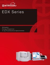
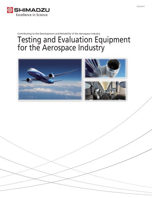
Contributing to <strong>the</strong> Development <strong>and</strong> Reliability of <strong>the</strong> <strong>Aerospace</strong> <strong>Industry</strong><br />
<strong>Testing</strong> <strong>and</strong> <strong>Evaluation</strong> <strong>Equipment</strong><br />
<strong>for</strong> <strong>the</strong> <strong>Aerospace</strong> <strong>Industry</strong><br />
C220-E011
Shimadzu's Material Strength <strong>Testing</strong> <strong>and</strong><br />
<strong>Evaluation</strong> <strong>Equipment</strong> Contributes to<br />
<strong>the</strong> Ongoing Development of <strong>Aerospace</strong> Materials
Diverse metal materials, organic materials, inorganic materials,<br />
<strong>and</strong> composite materials (FRP, MMC, CMC) are used in aircraft,<br />
satellites, spacecraft, rockets, <strong>and</strong> space robots. Such materials<br />
have been developed to provide <strong>the</strong> required properties of<br />
lightness, strength, durability, heat resistance, <strong>and</strong> machinability.<br />
To ensure <strong>the</strong> safety of designed <strong>and</strong> manufactured aircraft,<br />
mechanical properties are measured <strong>and</strong> evaluated in terms of<br />
<strong>the</strong>ir structure, strength, <strong>and</strong> material per<strong>for</strong>mance. <strong>Evaluation</strong>s<br />
are per<strong>for</strong>med according to <strong>the</strong> various environments to which<br />
aircraft <strong>and</strong> space transfer vehicles are directly subjected.<br />
Examples of such evaluations include static testing to evaluate <strong>the</strong><br />
strength <strong>and</strong> rigidity of aircraft materials <strong>and</strong> structures, dynamic<br />
testing to determine <strong>the</strong> strength with respect to fatigue <strong>and</strong><br />
vibrations, <strong>and</strong> impact testing to evaluate <strong>the</strong> impact strength<br />
<strong>and</strong> fracture properties.<br />
Shimadzu is applying it's technical expertise cultivated through<br />
both physical testing in materials development <strong>and</strong> full-scale<br />
testing in quality control in order to develop materials <strong>for</strong><br />
aerospace applications. Utilize Shimadzu's extensive knowledge<br />
of materials testing <strong>and</strong> evaluation <strong>for</strong> your application.<br />
Sample temperature 2000°C<br />
Ultra-High-Temperature <strong>Testing</strong> in an Oxidizing Atmosphere<br />
with a High-Frequency Induction Heating Furnace<br />
When a space transfer vehicle re-enters <strong>the</strong> atmosphere, <strong>the</strong> temperature<br />
exceeds one thous<strong>and</strong> several h<strong>and</strong>red degrees. The development of<br />
materials that can withst<strong>and</strong> higher temperatures would permit <strong>the</strong><br />
design of more efficient space transfer vehicles.
Even Lighter Innovative Materials<br />
Materials used in aircraft can be broadly categorized into metal,<br />
non-metal, <strong>and</strong> composite materials. All of <strong>the</strong>m are light but<br />
strong, <strong>and</strong> offer excellent machinability <strong>and</strong> heat resistance, <strong>and</strong><br />
have been developed to provide <strong>the</strong> properties required <strong>for</strong><br />
aircraft.<br />
Metals are <strong>the</strong> major materials used in aircraft structures, of<br />
which <strong>the</strong> majority are aluminum alloys. Titanium alloys <strong>and</strong><br />
stainless steel are also used <strong>for</strong> parts around <strong>the</strong> afterburner <strong>and</strong><br />
<strong>for</strong> parts of <strong>the</strong> aircraft structure subjected to <strong>the</strong> jet exhaust.<br />
Since plastics are light, easy to color-mold, <strong>and</strong> transparent to<br />
electromagnetic waves, <strong>and</strong> also good electrical <strong>and</strong> <strong>the</strong>rmal<br />
insulators, <strong>the</strong>y are widely used in modern aircraft <strong>for</strong> <strong>the</strong><br />
window glass, interior material, <strong>and</strong> radome.<br />
Apart from applications as rein<strong>for</strong>cement in<br />
glass-fiber-rein<strong>for</strong>ced resins, glass materials are inserted between<br />
<strong>the</strong> aircraft outer surface <strong>and</strong> interior lining as sound <strong>and</strong><br />
<strong>the</strong>rmal insulators.<br />
As syn<strong>the</strong>tic rubber materials offer better wea<strong>the</strong>r resistance,<br />
heat resistance, oil resistance, <strong>and</strong> chemical resistance than<br />
natural rubber, <strong>the</strong>y are widely used in gaskets, packing, hoses,<br />
duct couplings, <strong>and</strong> waterproof sheets. Natural rubber is<br />
commonly used in aircraft tires due to superior rubber elasticity,<br />
tear strength, <strong>and</strong> abrasion resistance mechanical properties.<br />
Titanium alloy<br />
Stainless steel<br />
Ceramics<br />
Natural <strong>and</strong><br />
syn<strong>the</strong>tic rubber<br />
Glass fiber<br />
Aluminum alloy<br />
Carbon fiber<br />
Plastics<br />
4
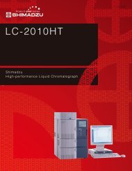
Growing Use of Composite Materials<br />
Composite materials combine different materials to achieve<br />
greater specific strength than is available from a single material.<br />
Fiber-rein<strong>for</strong>ced plastics (FRP) are typical composite materials.<br />
Among <strong>the</strong>se are glass-fiber-rein<strong>for</strong>ced plastics (GFRP), which are<br />
widely used <strong>for</strong> aircraft wing fillets, fairings, control surfaces,<br />
radomes, wing tips, <strong>and</strong> cabin floors. Widely used in important<br />
components such as aircraft wings, center wing boxes, <strong>and</strong><br />
horizontal <strong>and</strong> vertical stabilizers, carbon-fiber-rein<strong>for</strong>ced plastics<br />
(CFRP) combine plastics with carbon fibers having high specific<br />
modulus of elasticity <strong>and</strong> specific strength.<br />
The evaluation of fundamental mechanical properties is essential<br />
<strong>for</strong> new materials, such as composites. Ongoing st<strong>and</strong>ardization<br />
of sample shapes <strong>and</strong> test methods is intended to improve <strong>the</strong><br />
stability of material quality <strong>and</strong> enhance reliability.<br />
Pressure bulkhead<br />
Wing leading edge<br />
Wing<br />
Center wing box<br />
Vertical stabilizer<br />
Floor beam<br />
Horizontal stabilizer<br />
Tail cone<br />
Flap track panels<br />
Tail fuselage<br />
L<strong>and</strong>ing gear door<br />
Engine cowl<br />
Some Parts in Which CFRP Is Used<br />
Aircraft are designed to meet <strong>the</strong> requirements indicated in <strong>the</strong> design st<strong>and</strong>ards. Inspection <strong>and</strong><br />
testing of <strong>the</strong> aircraft structure <strong>and</strong> strength are per<strong>for</strong>med at <strong>the</strong> manufacturing stage <strong>and</strong> flight<br />
testing is conducted to confirm <strong>the</strong> per<strong>for</strong>mance <strong>and</strong> flying quality of <strong>the</strong> completed aircraft.<br />
<strong>Testing</strong> includes static <strong>and</strong> fatigue testing at <strong>the</strong> materials development stage, endurance testing of all<br />
parts <strong>and</strong> components, <strong>and</strong> impact testing to evaluate <strong>the</strong> fast fracture characteristics of <strong>the</strong> materials.<br />
In recent years, it has become more important to observe fracture behavior. High-speed video<br />
cameras are now commonly used to per<strong>for</strong>m more sophisticated evaluations through<br />
synchronized observations of <strong>the</strong> tested material behavior <strong>and</strong> <strong>the</strong> S-S curve.<br />
Static testing<br />
Dynamic testing<br />
Fatigue <strong>and</strong><br />
endurance testing<br />
Impact testing<br />
Observations of<br />
fracture behavior<br />
For <strong>the</strong> tensile testing of composite materials such as<br />
CFRP, it is important to firmly grasp <strong>the</strong> sample,<br />
without twisting it. Hydraulic parallel tightening grips<br />
are ideal <strong>for</strong> tensile testing, as <strong>the</strong>y firmly grasp <strong>the</strong><br />
samples completely straight <strong>and</strong> without slippage.<br />
<strong>Testing</strong> <strong>and</strong> <strong>Evaluation</strong> <strong>Equipment</strong><br />
<strong>for</strong> <strong>the</strong> <strong>Aerospace</strong> <strong>Industry</strong><br />
Solutions <strong>for</strong> <strong>Aerospace</strong> <strong>Testing</strong><br />
5
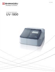
Strength <strong>Testing</strong> <strong>and</strong> Fracture Observations <strong>for</strong> CFRP<br />
— Imaging at Up to One Million Frames Per Second —<br />
Tensile-Impact Strength <strong>Testing</strong> <strong>and</strong> Fracture Observations <strong>for</strong> CFRP<br />
The development of composite materials requires not only static testing to verify<br />
functionality but also testing to determine impact strength <strong>and</strong> crack<br />
propagation.<br />
As an example, we used a high-speed tensile impact tester toge<strong>the</strong>r with a<br />
high-speed video camera to observe <strong>the</strong> tensile impact fracture of CFRP samples.<br />
Images were acquired by using <strong>the</strong> tester to output an imaging start signal<br />
synchronized with <strong>the</strong> tensile load to externally trigger <strong>the</strong> camera. We also used<br />
strobe lighting equipment to synchronize <strong>the</strong> illumination to <strong>the</strong> imaging timing.<br />
The combination of an impact tester <strong>and</strong> high-speed video camera permits <strong>the</strong><br />
evaluation of material impact properties <strong>and</strong> <strong>the</strong> observation of fracture<br />
properties simultaneously. This supports <strong>the</strong> development of a wide range of<br />
materials from individual functional resins to composite materials.<br />
Imaging trigger<br />
HYPER<br />
VISION<br />
Max. tensile speed<br />
20 m/s<br />
High-speed video camera<br />
Strobe light source<br />
HITS-T10 high-speed tensile tester<br />
Controller<br />
Test <strong>for</strong>ce data<br />
PC<br />
Images<br />
1 million fps max.<br />
System Configuration<br />
0 μs<br />
4 μs<br />
8 μs<br />
12 μs<br />
16 μs<br />
20 μs<br />
24 μs<br />
28 μs<br />
CFRP unidirectional (UD) material<br />
High-speed observations of fracture behavior<br />
250,000 fps<br />
Sample: L20 × W6.25 × T0.3 mm<br />
Loading rate: 6 m/s (22 km/h)<br />
6
JAXA (Japan <strong>Aerospace</strong> Exploration Agency)<br />
Products were developed based on joint research with <strong>the</strong> Advanced<br />
Composites Group, <strong>Aerospace</strong> Research <strong>and</strong> Development Directorate<br />
at JAXA, according to Promotion Program <strong>for</strong> Output Utilization<br />
— 300 kHz Data Acquisition —<br />
Static Tensile Strength <strong>Testing</strong> <strong>and</strong> Fracture Behavior Observations <strong>for</strong> CFRP<br />
Tensile testing <strong>and</strong> evaluation of CFRP dem<strong>and</strong>s not only <strong>the</strong><br />
acquisition of conventional S-S curves but also observations of fracture<br />
behavior in order to achieve more detailed analysis of strength<br />
properties.<br />
Shimadzu achieves observations of <strong>the</strong> CFRP fracture process at high<br />
temporal resolution through 300 kHz test-<strong>for</strong>ce data storage, fracture<br />
detection by a load amplifier, <strong>and</strong> trigger signal output to a<br />
high-speed video camera (100 continuous frames at one million fps).<br />
A rigid <strong>and</strong> specially-shaped lower grip was developed to accurately<br />
transmit sudden reductions in test <strong>for</strong>ce to <strong>the</strong> load cell, so that<br />
reliable observations of fracture behavior are ensured.<br />
Special Autograph AG-Xplus with <strong>the</strong><br />
latest measurement control functions<br />
HyperVision high-speed video camera<br />
with <strong>the</strong> highest specs in its class<br />
HPV-2A high-speed video camera<br />
Lower grip<br />
AG-X + HyperVision + novel lower grip<br />
Tester internal amplifier<br />
300 kHz<br />
Data sampling<br />
Imaging trigger<br />
HYPER VISION<br />
Autograph series<br />
Lower grip<br />
High-speed video camera<br />
Images<br />
PC<br />
Test <strong>for</strong>ce data acquired at 300 kHz<br />
Video data acquired at up to 1 million fps<br />
System Configuration<br />
0 μs 4 μs 8 μs 16 μs 20 μs 24 μs<br />
CFRP 0° unidirectional (UD) material<br />
High-speed observations of fracture behavior<br />
250,000 fps<br />
Sample: L160 × W20 × T0.57 mm<br />
Loading rate: 2 mm/min<br />
<strong>Testing</strong> <strong>and</strong> <strong>Evaluation</strong> <strong>Equipment</strong><br />
<strong>for</strong> <strong>the</strong> <strong>Aerospace</strong> <strong>Industry</strong><br />
Solutions <strong>for</strong> <strong>Aerospace</strong> <strong>Testing</strong><br />
7
Designing <strong>for</strong> Safety<br />
An underst<strong>and</strong>ing of <strong>the</strong> material fatigue properties under a variety of<br />
environments <strong>and</strong> situations provides important indicators at <strong>the</strong><br />
design stage. Predicting <strong>the</strong> fatigue life of materials allows <strong>the</strong><br />
establishment of maintenance plans <strong>for</strong> periodic replacement of parts<br />
subjected to stress <strong>and</strong> <strong>for</strong> regular inspections to detect fine cracks in<br />
materials in order to replace <strong>the</strong>m be<strong>for</strong>e fracture occurs.<br />
There<strong>for</strong>e, underst<strong>and</strong>ing <strong>the</strong> fatigue properties of materials is<br />
important to ensure a long aircraft life, maintain passenger safety, <strong>and</strong><br />
guarantee reliable flying.<br />
Fatigue Strength <strong>Testing</strong> of Composite Materials<br />
ASTM D 3479/D 3479M-96<br />
Constant-Load Amplitude Tension-Tension Fatigue <strong>Testing</strong> of CFRP<br />
This jig can be used <strong>for</strong> <strong>the</strong> constant-load amplitude tension-tension fatigue testing in <strong>the</strong> direction of<br />
<strong>the</strong> fibers in CFRP unidirectional rein<strong>for</strong>ced materials or textile-rein<strong>for</strong>ced materials stacked in layers.<br />
Front-opening hydraulic grips offer superior ease-of-operation <strong>and</strong> high accuracy <strong>for</strong> tensile <strong>and</strong><br />
compression testing across a wide test-<strong>for</strong>ce range.<br />
Front-opening hydraulic grips<br />
Fatigue Strength <strong>Evaluation</strong> of GFRP<br />
For aircraft materials such as composites that have been in use <strong>for</strong> many years, great weight is placed<br />
on impact resistance <strong>and</strong> fatigue strength according to <strong>the</strong> environment in which <strong>the</strong>y were used.<br />
As an example, we per<strong>for</strong>med fatigue testing on GFRP <strong>and</strong> <strong>the</strong>n plotted <strong>the</strong> resulting S-N curve to show<br />
<strong>the</strong> relationship between <strong>the</strong> maximum load stress among <strong>the</strong> six stress st<strong>and</strong>ards (one sample per<br />
st<strong>and</strong>ard) <strong>and</strong> <strong>the</strong> number of cycles to sample fracture. Internal observations reveal that glass fibers<br />
inside <strong>the</strong> sample that had no particular orientation be<strong>for</strong>e fatigue testing began to align somewhat in<br />
<strong>the</strong> direction of loading after one million load cycles, <strong>and</strong> were uni<strong>for</strong>mly aligned vertically just be<strong>for</strong>e<br />
fracture.<br />
Sample Held in Manual Grips <strong>for</strong> Flat Samples<br />
S-N Curve <strong>for</strong> GFRP<br />
Repeated maximum stress (MPa)<br />
Number of cycles to fracture<br />
Start of fatigue testing<br />
After one million load cycles<br />
Be<strong>for</strong>e fracture<br />
Direction of loading<br />
Fatigue Test Results<br />
Internal X-Ray Images of GFRP<br />
8
Ax<br />
ial Force <strong>and</strong> Torsion Te<br />
sting an<br />
d <strong>Evaluation</strong><br />
A multiaxial stress situation is created by applying compound axial <strong>for</strong>ces<br />
(tensile or compression) <strong>and</strong> torsion to allow fatigue testing of structural<br />
materials under conditions close to actual-use conditions.<br />
Axial-<strong>for</strong>ce/torsion compound detector<br />
Detector <strong>for</strong> torsional displacement<br />
angle between gauge marks<br />
Axial-<strong>for</strong>ce/torsion i<br />
compound testing<br />
in resistance heating furnace<br />
Testin<br />
ing <strong>and</strong> Eval<br />
alua<br />
uati<br />
on<br />
in Cont<br />
ntro<br />
rolled-Temperature Environments<br />
The ambient temperature <strong>for</strong> materials used in aircraft <strong>and</strong> space transfer<br />
vehicles can extend across an extremely broad range from several tens to<br />
several hundreds of degrees below zero at <strong>the</strong> low-temperature end to plus<br />
several hundred to a thous<strong>and</strong> degrees at <strong>the</strong> high-temperature end.<br />
Strength testing under <strong>the</strong> same conditions as actual operation is required to<br />
evaluate <strong>the</strong> appropriate operational temperature range <strong>for</strong> each material.<br />
<strong>Testing</strong> g<strong>and</strong> evaluation in <strong>the</strong>rmostatic chamber<br />
Ultra-low-temperature tester<br />
Full-Scale <strong>Testing</strong> (Multi-<br />
Point Strain Measurements)<br />
The computer can read up to eight channels of strain gauge data synchronized<br />
with data from <strong>the</strong> tester, such as test <strong>for</strong>ce, stroke, <strong>and</strong> extensometer data.<br />
Multi-channel software permits data sampling synchronized with <strong>the</strong> load <strong>for</strong>ces<br />
by using multiple strain gauges affixed to <strong>the</strong> sample.<br />
Dynamic strain amplifier<br />
Strain data (8 channels)<br />
A/D board<br />
Test <strong>for</strong>ce <strong>and</strong> displacement data<br />
Autograph<br />
PC<br />
Multi-Channel Strain Measurement <strong>and</strong> <strong>Evaluation</strong> System<br />
Multi-Channel Software<br />
<strong>Testing</strong> <strong>and</strong> <strong>Evaluation</strong> <strong>Equipment</strong><br />
<strong>for</strong> <strong>the</strong> <strong>Aerospace</strong> <strong>Industry</strong><br />
Solutions <strong>for</strong> <strong>Aerospace</strong> <strong>Testing</strong><br />
9
Clarifying <strong>the</strong> Fatigue Fracture Mechanism<br />
The aging of today's commercial transport aircraft has caused <strong>the</strong><br />
relationship between design life <strong>and</strong> safety to be reviewed, resulting in<br />
<strong>the</strong> introduction of <strong>the</strong> concept of damage-tolerant design.<br />
Damage-tolerant design involves <strong>the</strong> investigation of fatigue crack<br />
propagation speed, initiation sites, <strong>and</strong> method of inspection. In<br />
practice, it is a method to design adequate residual strength, with<br />
respect to both single load transmission <strong>and</strong> multiple load<br />
transmission, to stop crack propagation or reduce propagation speed<br />
until <strong>the</strong> crack is discovered during maintenance.<br />
Fatigue, endurance, <strong>and</strong> reliability testing must be per<strong>for</strong>med on<br />
materials subjected to pressure fluctuations due to repeated take-offs<br />
<strong>and</strong> l<strong>and</strong>ings <strong>and</strong> high-altitude flight.<br />
Observations of Fatigue Fracture Behavior Using an SEM Servo<br />
Repeated loads applied during fatigue testing result in de<strong>for</strong>mation of <strong>the</strong> test sample.<br />
Even small movements that can be ignored on a macro scale appear extremely large<br />
when magnified by a scanning electron microscope (SEM). SEM images synchronized<br />
with <strong>the</strong> sample de<strong>for</strong>mation can be obtained by electrically moving <strong>the</strong> SEM<br />
field-of-view in synchronization with <strong>the</strong>se movements. The jigs holding <strong>the</strong> sample are<br />
compact enough to be installed inside <strong>the</strong> SEM sample chamber. The compact heating<br />
unit permits programmed heating of samples up to 800ºC to support a variety of tests.<br />
<br />
<br />
Fatigue <strong>Testing</strong> of SiC-Fiber-Ti-15-3<br />
Composite Material at 823 K (550ºC)<br />
Compact Test Jigs are Easily Installed in <strong>the</strong> SEM Sample Chamber<br />
ASTM E339 / E1820<br />
Fracture Toughness <strong>Testing</strong><br />
It is extremely important to design aircraft against fatigue. The pressure in <strong>the</strong> passenger<br />
cabin applies loads to <strong>the</strong> airframe during high-altitude flight. These become fatigue loads<br />
that are applied cyclically during each take-off <strong>and</strong> l<strong>and</strong>ing cycle.<br />
Fracture toughness testing involves applying static or dynamic loads to a notched sample<br />
to investigate <strong>the</strong> brittle crack initiation <strong>and</strong> propagation <strong>and</strong> <strong>the</strong> fracture conditions <strong>and</strong><br />
status.<br />
Special grips <strong>for</strong> compact test samples complying with ASTM st<strong>and</strong>ards, a COD bending<br />
test jig, <strong>and</strong> a crack opening displacement gauge support <strong>the</strong> evaluation of a material's<br />
fracture toughness <strong>and</strong> crack propagation.<br />
CT Sample Grips <strong>and</strong> Clip Gauge<br />
Fatigue Toughness <strong>Testing</strong> with a Resistancee Heating Tester<br />
COD Test Jig<br />
10
Gigacy<br />
cycl<br />
cl<br />
e Fati<br />
tigu<br />
e Test<br />
ing<br />
1000<br />
It is necessary to guarantee <strong>the</strong> long-term effective, reliable use of many<br />
products <strong>and</strong> equipment, including aircraft, automobiles, railways, marine<br />
structures, <strong>and</strong> electrical plants.<br />
To ensure <strong>the</strong> safety of engine turbine blades <strong>and</strong> wheel axles, <strong>the</strong><br />
conventional 10 7 cycle fatigue limit is no longer adequate; clarification of<br />
fatigue in <strong>the</strong> ultra-long-life range from 10 8 to 10 10 cycles is now needed<br />
<strong>for</strong> all materials.<br />
The piezo-electric element in <strong>the</strong> ultrasonic fatigue tester generates a<br />
vibration of 20 kHZ, which is amplified by <strong>the</strong> horn <strong>and</strong> transmitted to <strong>the</strong><br />
sample, to achieve oscillation rates of 20 kHz. This permits significantly<br />
shorter test cycle times.<br />
Test time (days)<br />
100<br />
10<br />
1<br />
20 Hz Hz General General fatigue fatigue tester<br />
tester<br />
300 Hz Hz High-cycle High-cycle fatigue fatigue tester tester<br />
20 kHz kHz USF-2000<br />
USF-2000<br />
1 kHz kHz Non-resonant Non-resonant fatigue fatigue tester tester<br />
0.1<br />
106 10 7 10 8 10 9 10 10 10 11<br />
Test Cycle<br />
Cycle Time Comparison Between Ultrasonic <strong>and</strong> Conventional Fatigue Testers<br />
Piezoelectric actuator<br />
Horn<br />
Sample<br />
Displacement Stress<br />
Stress Displacement<br />
USF Series Ultrasonic Fatigue Tester<br />
Schematic Representation of Test Force Loads on aSample<br />
More Efficient Discovery of Inclusions<br />
Fatigue fracture from inclusion initiation point<br />
Confirming whe<strong>the</strong>r samples contain inclusions <strong>and</strong> <strong>the</strong> subsequent<br />
analysis of any inclusion found is an effective way to ensure <strong>the</strong> supply of<br />
materials with high fatigue strength. When an ultrasonic fatigue tester is<br />
used to cause an internal fracture in <strong>the</strong> sample, <strong>the</strong> largest inclusion in<br />
<strong>the</strong> volume of <strong>the</strong> portion that has a potential risk to fracture becomes <strong>the</strong><br />
initiation point of <strong>the</strong> fracture. Inclusions can be easily detected by<br />
observing <strong>the</strong> fracture surfaces. This is a much more efficient method of<br />
inclusion detection than conventional methods.<br />
Permits discovery <strong>and</strong> analysis<br />
of inclusion in sample<br />
Images of Inclusion<br />
<strong>Testing</strong> <strong>and</strong> <strong>Evaluation</strong> <strong>Equipment</strong><br />
<strong>for</strong> <strong>the</strong> <strong>Aerospace</strong> <strong>Industry</strong><br />
Solutions <strong>for</strong> <strong>Aerospace</strong> <strong>Testing</strong><br />
11
Both Safety <strong>and</strong> Com<strong>for</strong>t<br />
Some flights last many hours. Good aircraft design is essential to<br />
provide a safe environment <strong>for</strong> both passengers <strong>and</strong> crew.<br />
Thermal insulation material such as glass wool is used in <strong>the</strong> so-called<br />
insulation blanket between <strong>the</strong> outer surface <strong>and</strong> interior lining of <strong>the</strong><br />
aircraft fuselage. It insulates <strong>the</strong> interior against <strong>the</strong> outer temperature<br />
<strong>and</strong> absorbs noise. It can protect <strong>the</strong> occupants from temperatures of<br />
several tens of degrees below zero at an altitude of 10,000 meters.<br />
Since openings such as doors <strong>and</strong> windows in <strong>the</strong> outer cladding<br />
reduce <strong>the</strong> structural strength of <strong>the</strong> aircraft, <strong>the</strong>y should be kept to a<br />
minimum <strong>and</strong> made as small as possible. However, <strong>the</strong>y are<br />
indispensable to prevent passengers from feeling claustrophobic or<br />
oppressed. Thorough strength testing <strong>and</strong> fatigue <strong>and</strong> endurance<br />
testing of materials are per<strong>for</strong>med to maintain passenger com<strong>for</strong>t in<br />
<strong>the</strong> aircraft <strong>and</strong> ensure safety.<br />
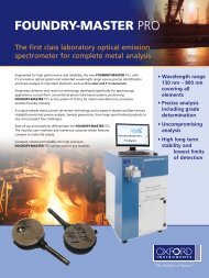
Compression <strong>Testing</strong> of Foam Plastics<br />
Due to <strong>the</strong>ir lightness, foam plastics are used in a variety of applications,<br />
including as <strong>the</strong>rmal insulation, sound insulation, <strong>and</strong> cushioning material.<br />
The graph on <strong>the</strong> right shows <strong>the</strong> results of compression testing on three<br />
types of foam plastic, each with a different foaming agent content. The<br />
low-foam plastic exhibits significantly higher compressive stress than <strong>the</strong><br />
o<strong>the</strong>r two types. It is apparent that <strong>the</strong> stress did not increase significantly<br />
above about 3 % strain <strong>for</strong> any of <strong>the</strong> samples.<br />
Stress (MPa)<br />
High-ratio foam<br />
Low-ratio foam<br />
Medium-ratio foam<br />
Strain (%)<br />
Stress – Strain Graph from Compression <strong>Testing</strong><br />
— TRViewX Video Type Non-Contact Extensometer —<br />
Applications of Measured Values <strong>for</strong> Actual Samples to CAE Analysis<br />
The Shimadzu TRViewX Video Type Non-Contact Extensometer offers<br />
world-leading per<strong>for</strong>mance. It offers ASTM E83 Class B2 (Class C in<br />
<strong>the</strong>rmostatic bath) elongation measurement accuracy <strong>and</strong> ASTM E83 Class<br />
C amplitude measurement accuracy per<strong>for</strong>mance. It supports measurement<br />
of composite materials, resin films, metal foils, <strong>and</strong> o<strong>the</strong>r materials which<br />
are difficult to measure with a conventional contact displacement gauge.<br />
In addition, it can record <strong>the</strong> sample status during testing or play back <strong>the</strong><br />
video in synchronization with <strong>the</strong> S-S curve.<br />
TRViewX Video Type Non-Contact Extensometer<br />
Endurance <strong>Testing</strong> of Syn<strong>the</strong>tic Yarn<br />
The per<strong>for</strong>mance of syn<strong>the</strong>tic fibers has improved dramatically. Lighter, tougher, <strong>and</strong> stronger, <strong>the</strong>y have a<br />
significant effect on <strong>the</strong> development of new materials in <strong>the</strong> aerospace field. The tensile testing <strong>and</strong><br />
repeated load testing of syn<strong>the</strong>tic yarns are indispensable <strong>for</strong> <strong>the</strong> development of syn<strong>the</strong>tic fibers.<br />
Polyester yarn was subjected to one million load cycles of a 2.14 N ±0.54 N, 10 Hz sinusoidal load. The results<br />
indicate a progressive degradation with a gradual increase in maximum/minimum elongation from 5.34/4.86<br />
mm at <strong>the</strong> start to 7.58/7.26 mm at <strong>the</strong> end.<br />
Maximum/minimum elongation (mm)<br />
Repeated cycles<br />
Repeated Cycles – Elongation Curve<br />
Polyethylene Yarn Held in Grips <strong>for</strong> Yarn<br />
12
Dyna<br />
nami<br />
c (I<br />
mpac<br />
t)<br />
Cle<br />
leav<br />
age Re<br />
si<br />
st<br />
an<br />
ce Tes<br />
t of<br />
Hig<br />
igh-<br />
Stre<br />
ngth<br />
Adh<br />
dhes<br />
ive Bo<br />
nds<br />
Joining parts toge<strong>the</strong>r with adhesives offers advantages, including<br />
improved fatigue resistance <strong>and</strong> stress distribution in <strong>the</strong> joint due to <strong>the</strong><br />
surface contact, over conventional bolted or welded joints. Research is still<br />
being conducted into adhesives <strong>and</strong> adhesion methods.<br />
Two materials with different surface-treatment conditions (SS400 stainless<br />
steel, with <strong>and</strong> without surface treatment) were stuck toge<strong>the</strong>r with a<br />
<strong>the</strong>rmosetting-resin adhesive to <strong>for</strong>m a symmetric wedge sample. Loads<br />
were applied to cleave <strong>the</strong> adhesive joint with a hardened steel wedge.<br />
The maximum test <strong>for</strong>ce <strong>and</strong> de<strong>for</strong>mation up to fracture differed according<br />
to whe<strong>the</strong>r or not surface treatment had been per<strong>for</strong>med. The adhesion<br />
surfaces also appeared different after debonding.<br />
Upper grip<br />
Symmetric wedge sample<br />
Wedge<br />
Spacer<br />
Lower grip<br />
Sample Mounted in Tester<br />
With surface treatment<br />
Without surface treatment<br />
Test <strong>for</strong>ce (KN)<br />
<br />
Cohesive fracture<br />
Interfacial debonding<br />
Displacement (mm)<br />
With surface<br />
treatment<br />
Without surface<br />
treatment<br />
Test Force – Displacement Curve from Impact Cleavage <strong>Testing</strong><br />
Observations of Sample Surfaces after Debonding<br />
<strong>Testing</strong> of Aircraft Window Materials<br />
Windows in <strong>the</strong> aircraft passenger cabin comprise a total of three layers of stretched or<br />
non-stretched acrylic sheet <strong>and</strong> polycarbonate sheet. These are fastened with a sealant into <strong>the</strong><br />
window openings in <strong>the</strong> external skin. Even if one of <strong>the</strong> two outer sheets is lost, <strong>the</strong> remaining<br />
sheet must be able to withst<strong>and</strong> <strong>the</strong> maximum pressure loads from <strong>the</strong> passenger cabin, air<br />
<strong>for</strong>ces, <strong>and</strong> external temperature.<br />
Three- <strong>and</strong> four-point bending testing, ring bending testing, <strong>and</strong> compression testing are<br />
generally used to evaluate <strong>the</strong> strength of window materials. Surface coatings are evaluated<br />
using hardness testing <strong>and</strong> friction <strong>and</strong> wear testing.<br />
Strength <strong>and</strong> Endurance <strong>Testing</strong> of Electronic Components<br />
An aircraft is packed with various kinds of sensors <strong>and</strong> electronic equipment, including wea<strong>the</strong>r radar <strong>and</strong><br />
wireless communication devices. As such important equipment is directly related to <strong>the</strong> flight of <strong>the</strong> aircraft, it<br />
must be durable enough to prevent defects over a long period of use. Surface-mounted electronic<br />
components on circuit boards must be subjected to stringent testing under many hypo<strong>the</strong>tical situations of<br />
bonding <strong>for</strong>ces, shear peeling <strong>for</strong>ces, <strong>and</strong> stresses due to repeated <strong>the</strong>rmal expansion <strong>and</strong> contraction cycles.<br />
Endurance <strong>Testing</strong> of a Printed Circuit Board<br />
<strong>Testing</strong> <strong>and</strong> <strong>Evaluation</strong> <strong>Equipment</strong><br />
<strong>for</strong> <strong>the</strong> <strong>Aerospace</strong> <strong>Industry</strong><br />
Solutions <strong>for</strong> <strong>Aerospace</strong> <strong>Testing</strong><br />
13
Faster, Fur<strong>the</strong>r, <strong>and</strong> More Efficient<br />
The combustion chambers <strong>and</strong> <strong>the</strong> turbine rotor blades <strong>and</strong><br />
stator vanes in <strong>the</strong> aircraft turbofan <strong>and</strong> o<strong>the</strong>r jet engines<br />
operate in <strong>the</strong> severest of environments. Maximum temperatures<br />
significantly exceed 1000ºC. The turbine inlet temperature may<br />
be higher than 1500ºC in modern, large, high-per<strong>for</strong>mance jet<br />
engines.<br />
There<strong>for</strong>e, super-heat-resisting alloys are <strong>the</strong> major materials<br />
used <strong>for</strong> such core components of jet engines. It is no<br />
exaggeration to say that dramatic advances in <strong>the</strong>se super alloys<br />
<strong>and</strong> in <strong>the</strong> manufacturing processes <strong>for</strong> high-temperature parts<br />
have directly led to larger <strong>and</strong> faster aircraft with higher output<br />
<strong>and</strong> better fuel efficiency.<br />
The development of such materials dem<strong>and</strong>s <strong>the</strong> evaluation of<br />
<strong>the</strong>ir mechanical properties in <strong>the</strong> actual operating environment.<br />
Shimadzu supports such testing by combining a materials tester<br />
with environment control equipment.<br />
Hi<br />
gh<br />
-Tem<br />
empe<br />
ratu<br />
ture<br />
<strong>Testing</strong><br />
Sys<br />
tem Using Hi<br />
gh-Frequenen<br />
cy Induc<br />
uction<br />
Heati<br />
ting<br />
The high-temperature testing system exploits <strong>the</strong> characteristics of<br />
high-frequency induction heating <strong>for</strong> a range of high-temperature tests.<br />
The types of testing per<strong>for</strong>med include general high-temperature/low-cycle<br />
fatigue testing; <strong>the</strong>rmal fatigue testing with a chiller;<br />
high-temperature/low-cycle testing, <strong>the</strong>rmal fatigue testing, or simulated<br />
<strong>the</strong>rmal cycle testing in a vacuum or inert-gas atmosphere within an<br />
atmosphere conditioning chamber; crack propagation testing or fracture<br />
toughness testing on CT or CCT samples; superplastic de<strong>for</strong>mation testing;<br />
<strong>and</strong> creep testing.<br />
High-Temperature <strong>Testing</strong> System Using High-Frequency Induction Heating<br />
Evaluati<br />
ng Creep<br />
ep Properties at 160<br />
0ºC<br />
Creep testing <strong>and</strong> stress rupture testing of materials at high temperatures<br />
are extremely important methods <strong>for</strong> acquiring detailed data <strong>for</strong><br />
component design in <strong>the</strong> aerospace industry. Creep testing involves<br />
applying a constant load to a material maintained at constant temperature<br />
to de<strong>for</strong>m <strong>the</strong> sample. The relationship between <strong>the</strong> de<strong>for</strong>mation <strong>and</strong> time<br />
is measured. Stress rupture testing measures <strong>the</strong> time to fracture of a<br />
sample under constant load <strong>and</strong> temperature.<br />
Data <strong>for</strong> measurement of <strong>the</strong> turbine blade service life can be acquired<br />
from <strong>the</strong> creep <strong>and</strong> stress rupture data <strong>for</strong> <strong>the</strong> high-per<strong>for</strong>mance materials.<br />
As a result, <strong>the</strong> turbine blade de<strong>for</strong>mation rate can be predicted, allowing<br />
<strong>the</strong> blades to be replaced be<strong>for</strong>e <strong>the</strong>y contact <strong>the</strong> engine casing. This data<br />
can be used to create a maintenance plan that requires turbine blade<br />
replacement after a certain period of operation.<br />
Creep Characteristics <strong>Evaluation</strong> Tester<br />
14
Examples of Applicable St<strong>and</strong>ards<br />
ASTM D 3039 /D 3039M-07<br />
ASTM D 3518 /D 3518M-94<br />
ASTM D 5766 /D 5766M-11<br />
Static Tensile <strong>Testing</strong> of CFRP<br />
Tensile testing was per<strong>for</strong>med on JIS K7073-1988 Type IV samples (strip sample<br />
with no tabs, fiber direction perpendicular to direction of tensile load), with an<br />
extensometer attached <strong>for</strong> strain measurement in tensile direction <strong>and</strong> a width<br />
sensor to measure strain perpendicular to <strong>the</strong> tensile direction.<br />
Poisson's ratio is approximately 0.3 <strong>for</strong> mild steel <strong>and</strong> 0.46 to 0.49 <strong>for</strong> elastic<br />
rubber. However, <strong>the</strong> value of 0.06 is an order of magnitude smaller <strong>for</strong> CFRP,<br />
showing that its de<strong>for</strong>mations are extremely low.<br />
Be<strong>for</strong>e<br />
test<br />
After<br />
fracture<br />
Width sensor<br />
perpendicular<br />
to tensile direction<br />
Extensometer in<br />
tensile direction<br />
Sample<br />
Stress (MPa)<br />
Tensile modulus calculated as 5.76 × 10 5 MP<br />
across 100 to 300 MPa stress range<br />
Stress (MPa)<br />
Poisson's ratio calculated as 6.0 × 10 -2<br />
across 100 to 300 MPa stress range<br />
Displacement gauge 1 (strain) (%)<br />
Stress – Strain Diagram<br />
Width sensor (mm)<br />
Stress – Width-Direction Displacement Diagram<br />
ASTM E1012<br />
Axial Adjustment <strong>for</strong> <strong>Testing</strong><br />
Axial adjustment of <strong>the</strong> tester is extremely important to reduce <strong>the</strong> risk of breaking samples at <strong>the</strong> chuck<br />
during tensile testing of CFRP or GFRP. Axial adjustment is often a prerequisite <strong>for</strong> <strong>the</strong> stable acquisition of<br />
data <strong>for</strong> aircraft-grade CFRP.<br />
This axial adjustment system provides a test environment con<strong>for</strong>ming to ASTM E1012, enhancing <strong>the</strong><br />
reliability of <strong>the</strong> data.<br />
Axial Adjustment System<br />
The axial adjustment system uses an axial-center sensor, strain amplifier unit, <strong>and</strong> special axial adjustment<br />
software to adjust <strong>the</strong> inclination between grip centers <strong>and</strong> to adjust <strong>the</strong> axis in <strong>the</strong> horizontal direction.<br />
Eliminating bending stresses <strong>and</strong> lateral shear stresses on <strong>the</strong> sample ensures highly reliable data.<br />
Axial Adjustment Software<br />
When loads are applied to <strong>the</strong> special sample, this dedicated software reads <strong>the</strong> signals from <strong>the</strong> strain<br />
gauge attached to <strong>the</strong> sample. The axis can be adjusted by manual movements of <strong>the</strong> adjustment jig based<br />
on this in<strong>for</strong>mation.<br />
<strong>Testing</strong> <strong>and</strong> <strong>Evaluation</strong> <strong>Equipment</strong><br />
<strong>for</strong> <strong>the</strong> <strong>Aerospace</strong> <strong>Industry</strong><br />
Solutions <strong>for</strong> <strong>Aerospace</strong> <strong>Testing</strong><br />
15
<strong>Testing</strong> Compliant with Various CFRP <strong>Testing</strong> St<strong>and</strong>ards<br />
ASTM D6484 / D6484M<br />
Open-Hole Compression Strength <strong>Testing</strong> on Polymer Matrix Composite Laminate<br />
ASTM D6484 is a typical method used to determine <strong>the</strong> compressive strength of<br />
CFRP open-hole samples. This is a shear-<strong>for</strong>ce method that applies a <strong>for</strong>ce in <strong>the</strong><br />
longitudinal direction to both sides of <strong>the</strong> sample to determine <strong>the</strong> compressive<br />
strength of <strong>the</strong> holes.<br />
On <strong>the</strong> o<strong>the</strong>r h<strong>and</strong>, <strong>the</strong> method prescribed in JIS K7093 is an end-load method<br />
that directly applies compression <strong>for</strong>ces to <strong>the</strong> ends of <strong>the</strong> sample to determine<br />
its compressive strength. It is known to provide results equivalent to those<br />
obtained by <strong>the</strong> ASTM D6484 method, while using smaller samples <strong>and</strong> jigs.<br />
ASTM D7137 / D7137M<br />
<strong>Testing</strong> <strong>the</strong> Compressive Residual Strength Characteristics of<br />
a Damaged Polymer Matrix Composite Plate<br />
Compression testing according to ASTM D7137 / D7137M is intended <strong>for</strong> samples damaged<br />
by impact testing. The impact testing is prescribed in ASTM D7136. This jig was developed by<br />
<strong>the</strong> Boeing Company. The testing is per<strong>for</strong>med on rectangular samples made of composite<br />
material that have already been subjected to impact testing. The sample is mounted on <strong>the</strong><br />
jig <strong>and</strong> subjected to compression loads. The load at fracture is <strong>the</strong>n compared to <strong>the</strong><br />
compression strength it exhibits when no impact <strong>for</strong>ce has been applied, so that <strong>the</strong> residual<br />
strength of <strong>the</strong> sample can be determined. Determining <strong>the</strong> damage resistance of layered<br />
composite plates is useful <strong>for</strong> product development <strong>and</strong> material selection.<br />
ASTM D5379 / D5379M<br />
JIS K7079-2<br />
In-Plane Shear <strong>Testing</strong>—Double-V-Notched Sample Shearing<br />
The in-plane shear strength, in-plane shear fracture strain, <strong>and</strong> in-plane shear<br />
elastic modulus of carbon-fiber-rein<strong>for</strong>ced plastics can be determined by <strong>the</strong><br />
Iosipescu test, which is an in-plane shear test on double-V-notched samples. This<br />
testing method is applicable to unidirectional (UD) materials <strong>and</strong> laminates<br />
comprising unidirectional rein<strong>for</strong>cing layers or textile rein<strong>for</strong>cing layers (cross<br />
laminates, quasi-isotropic laminates, etc.).<br />
ASTM D7078 / D7078M<br />
V-Notched Rail Shear <strong>Testing</strong> <strong>and</strong> <strong>Evaluation</strong> of Composites<br />
This testing applies shear <strong>for</strong>ces to mounted samples with 90-degree V-notches<br />
at <strong>the</strong> top <strong>and</strong> bottom. In ASTM D5379, loads are applied to <strong>the</strong> top <strong>and</strong><br />
bottom ends of <strong>the</strong> sample, while in ASTM D7078, <strong>the</strong> surfaces are grasped to<br />
apply higher shear loads. It permits testing of larger samples than those<br />
specified by ASTM D5379.<br />
16
ASTM D4255 / D4255<br />
JIS K7079<br />
In-Plane Shear <strong>Testing</strong><br />
The in-plane shear test jig is designed to test fiber-rein<strong>for</strong>ced plastics. This test<br />
method is generally called <strong>the</strong> two-rail method. The jig mechanism easily<br />
generates in-plane shear on <strong>the</strong> sample to achieve stable test results.<br />
ASTM D6641 / D6641M<br />
Compression <strong>Testing</strong> <strong>and</strong> <strong>Evaluation</strong> of Polymer Matrix Composite<br />
Laminate Using a Combined Loading Compression (CLC) Test Jig<br />
Combined loading compression (CLC) testing uses a combination of shear loads<br />
<strong>and</strong> end face loads. This method uses strip test samples with no tabs. It offers<br />
<strong>the</strong> advantage of simultaneous strength <strong>and</strong> elastic-modulus measurements.<br />
In this method, a strip sample is held vertically by pairs of upper <strong>and</strong> lower<br />
blocks with <strong>the</strong>ir top <strong>and</strong> bottom faces aligned with <strong>the</strong> top <strong>and</strong> bottom ends of<br />
<strong>the</strong> sample in order to directly compress <strong>the</strong> sample from its top end.<br />
ASTM D6671/ D6671M<br />
<strong>Evaluation</strong> of Interlaminar Fracture Toughness of CFRP Cross Laminate by MMB <strong>Testing</strong><br />
As CFRP composites are laminated <strong>for</strong> practical use, <strong>the</strong>y have low interlaminar fracture<br />
strength <strong>and</strong> interlaminar fracture toughness. There<strong>for</strong>e, when <strong>the</strong> materials are subjected to<br />
shock loads, delamination cracks readily <strong>for</strong>m between <strong>the</strong> layers, which can become initiation<br />
points <strong>for</strong> fracture. Generally, <strong>the</strong> crack-tip de<strong>for</strong>mation modes are Mode I (open type), Mode<br />
II (in-plane shear type), Mode III (out-of-plane shear type), or a combination of <strong>the</strong> three. As<br />
delamination occurs due to a mixed de<strong>for</strong>mation mode where Mode I <strong>and</strong> Mode II occur<br />
simultaneously, it is important to evaluate <strong>the</strong> mixed-mode fracture toughness.<br />
This jig is used <strong>for</strong> mixed-mode bending (MMB) testing by applying a combination of Mode I <strong>and</strong> Mode<br />
II de<strong>for</strong>mations to flat fiber-rein<strong>for</strong>ced plastic materials to measure <strong>the</strong> fracture toughness values.<br />
ASTM D2344 / D2344M<br />
ASTM D790<br />
ASTM D6272<br />
ASTM D7264 / D7264M<br />
ISO178JIS K7171<br />
Three- <strong>and</strong> Four-Point Bending <strong>Testing</strong><br />
The bending properties of plastics are important <strong>for</strong> numerous applications. Various<br />
st<strong>and</strong>ards describe appropriate testing procedures. Three- or four-point bending testing is<br />
used to measure <strong>the</strong> strength properties of comparatively rigid materials. For this type of<br />
testing, it is recommended to directly measure <strong>the</strong> sample strain using deflection gauges<br />
or o<strong>the</strong>r strain gauges. As <strong>the</strong> fulcrum span is determined according to <strong>the</strong> sample<br />
thickness, it is important to know <strong>the</strong> range of sample dimensions be<strong>for</strong>e selecting <strong>the</strong> jig.<br />
<strong>Testing</strong> <strong>and</strong> <strong>Evaluation</strong> <strong>Equipment</strong><br />
<strong>for</strong> <strong>the</strong> <strong>Aerospace</strong> <strong>Industry</strong><br />
Solutions <strong>for</strong> <strong>Aerospace</strong> <strong>Testing</strong><br />
17
Shimadzu Materials Testers<br />
Precision Universal Testers<br />
Autograph AG-Xplus Series<br />
To alleviate <strong>the</strong> burden on <strong>the</strong> environment, this series features a power-saving<br />
function as st<strong>and</strong>ard to reduce <strong>the</strong> power consumption in a st<strong>and</strong>by state by<br />
10% to 25% in comparison to previous models. The short-column model (SC<br />
model) <strong>and</strong> high-speed model (HS model) have been newly added to <strong>the</strong><br />
product range. The control resolution has been increased by a factor of eight to<br />
improve <strong>the</strong> reliability of testing, <strong>and</strong> auto-tuning makes stress control <strong>and</strong><br />
strain control simple.<br />
High-speed sampling in just 0.2 milliseconds (5 kHz) captures even sharp<br />
fluctuations in test <strong>for</strong>ce when a brittle material fails.<br />
Video Type Non-Contact Extensometer<br />
TRViewX<br />
The TRViewX permits accurate measurements across a wide range of<br />
elongations, without affecting <strong>the</strong> sample. It even permits measurement of films<br />
that are difficult to measure with a conventional contact extensometer. It offers<br />
extension measurements with accuracy equivalent to JIS B7741 Class 0.5.<br />
Material <strong>Testing</strong> Operation Software<br />
TRAPEZIUM X<br />
Now compatible with Windows 7, TRAPEZIUM X offers data search <strong>and</strong> preview<br />
functions <strong>and</strong> allows <strong>the</strong> user to create reports with a flexible layout. In addition,<br />
its visual wizard settings, Quick Panel, <strong>and</strong> Quick Parameter List make it possible<br />
to per<strong>for</strong>m a wide range of operations, from simple test control to testing based<br />
on complex user-defined test patterns.<br />
High-Speed Video Camera<br />
HyperVision HPV-2A<br />
This high-speed video camera offers a high 312 × 260 pixel (approx. 81 kpixel)<br />
resolution at all imaging speeds up to ultra-fast imaging at one million frames<br />
per second. Four cameras can be operated from a single computer to achieve<br />
fully synchronized imaging.<br />
18
Electromagnetic Force Fatigue/Endurance <strong>Testing</strong> Systems<br />
Servopulser EMT Series<br />
This series of fatigue <strong>and</strong> endurance testing systems uses a quiet, clean, <strong>and</strong><br />
oil-free electromagnetic actuator. It permits rapid cycle testing with a maximum<br />
test stroke of ±50 mm at speeds up to 2 m/s. The test space is large enough to<br />
mount an optional <strong>the</strong>rmostatic chamber <strong>for</strong> testing in controlled environments.<br />
Electromagnetic Force Micro Material Testers<br />
Micro-Servo MMT Series<br />
This series of fatigue testers uses a quiet, clean, <strong>and</strong> oil-free electromagnetic<br />
actuator. The four models in <strong>the</strong> product range offer maximum test <strong>for</strong>ces from<br />
10 N to 500 N. They offer rapid cycle testing with gram-order test <strong>for</strong>ces <strong>and</strong><br />
micron-level accuracy. These testers are ideal <strong>for</strong> dynamic strength evaluations<br />
of minute materials <strong>and</strong> parts.<br />
Ultrasonic Fatigue Tester<br />
USF-2000<br />
This fatigue tester uses ultrasonic vibrations to per<strong>for</strong>m rapid, gigacycle-order<br />
fatigue testing of materials.<br />
It offers an ultra-fast 20 kHz test frequency. The test stress range is from 180 to<br />
900 MPa. Use <strong>the</strong> computer supplied <strong>for</strong> monitoring <strong>and</strong> test condition setup.<br />
High-Speed Impact Testers<br />
Hydroshot HITS Series<br />
Dem<strong>and</strong>s <strong>for</strong> increased safety <strong>and</strong> reliability make <strong>the</strong> evaluation of <strong>the</strong> dynamic<br />
strength (impact characteristics) of materials <strong>and</strong> parts even more important.<br />
These instruments can capture maximum test <strong>for</strong>ce, energy, <strong>and</strong> displacement<br />
data at test rates up to 72 km/hour (20 m/s).<br />
The available models are <strong>the</strong> HITS-T10 tensile load type <strong>and</strong> HITS-P10 punch<br />
type. They support testing in temperature-controlled environments.<br />
<strong>Testing</strong> <strong>and</strong> <strong>Evaluation</strong> <strong>Equipment</strong><br />
<strong>for</strong> <strong>the</strong> <strong>Aerospace</strong> <strong>Industry</strong><br />
Solutions <strong>for</strong> <strong>Aerospace</strong> <strong>Testing</strong><br />
19
<strong>Testing</strong> <strong>and</strong> <strong>Evaluation</strong> <strong>Equipment</strong> <strong>for</strong> <strong>the</strong> <strong>Aerospace</strong> <strong>Industry</strong><br />
This brochure may contain references to products that are not available in your country.<br />
Please contact us to check <strong>the</strong> availability of <strong>the</strong>se products in your country.<br />
Company names, product/service names <strong>and</strong> logos used in this publication are trademarks <strong>and</strong> trade names of Shimadzu Corporation or its<br />
affiliates, whe<strong>the</strong>r or not <strong>the</strong>y are used with trademark symbol “TM” or “®”.<br />
Third-party trademarks <strong>and</strong> trade names may be used in this publication to refer to ei<strong>the</strong>r <strong>the</strong> entities or <strong>the</strong>ir products/services. Shimadzu<br />
disclaims any proprietary interest in trademarks <strong>and</strong> trade names o<strong>the</strong>r than its own.<br />
www.shimadzu.com/an/<br />
For Research Use Only. Not <strong>for</strong> use in diagnostic procedures.<br />
The contents of this publication are provided to you “as is” without warranty of any kind, <strong>and</strong> are subject to change without notice. Shimadzu<br />
does not assume any responsibility or liability <strong>for</strong> any damage, whe<strong>the</strong>r direct or indirect, relating to <strong>the</strong> use of this publication.<br />
© Shimadzu Corporation, 2013<br />
Printed in Japan 3655-11205-30AIT