Thermal Infrared Imaging Spectrometer (TIRIS) Status ... - TechExpo
Thermal Infrared Imaging Spectrometer (TIRIS) Status ... - TechExpo
Thermal Infrared Imaging Spectrometer (TIRIS) Status ... - TechExpo

Create successful ePaper yourself
Turn your PDF publications into a flip-book with our unique Google optimized e-Paper software.
<strong>Infrared</strong> Technology & Applications XXIII SPIE Vol. 3061, April 1997; Orlando, FL<br />
<strong>Thermal</strong> <strong>Infrared</strong> <strong>Imaging</strong> <strong>Spectrometer</strong> (<strong>TIRIS</strong>) <strong>Status</strong> Report<br />
Nahum Gat a , Suresh Subramanian a , Steve Ross a , Clayton LaBaw b , Jeff Bond c<br />
a<br />
Opto-Knowledge Systems Inc. (OKSI), 4030 Spencer St, Suite 108, Torrance CA 90503-2442<br />
b<br />
Jet Propulsion Laboratory, Pasadena, CA 91109<br />
c<br />
U.S. Army SSDC, Huntsville, AL 35807-3801<br />
ABSTRACT<br />
The <strong>TIRIS</strong> is a pushbroom long wave infrared imaging spectrometer designed to operate in the 7.5-14.0 µm spectral region from<br />
an airborne platform, using uncooled optics. The focal plane array is a 64x20 extrinsic Si:As detector operating at 10K, providing<br />
64 spectral bands with 0.1 µm spectral resolution, and 20 spatial pixels with 3.6 milliradians spatial resolution. A custom<br />
linear variable filter mounted over the focal plane acts to suppress near field radiation from the uncooled external optics. This<br />
dual-use sensor is developed to demonstrate the detection of plumes of toxic gases and pollutants in a downlooking mode.<br />
Keywords: <strong>Imaging</strong> <strong>Spectrometer</strong>, Hyperspectral, <strong>Thermal</strong> IR, Linear Variable Filter, Uncooled Optics, Plume Tracking, Chemical<br />
Detection, <strong>TIRIS</strong>.<br />
1. INTRODUCTION<br />
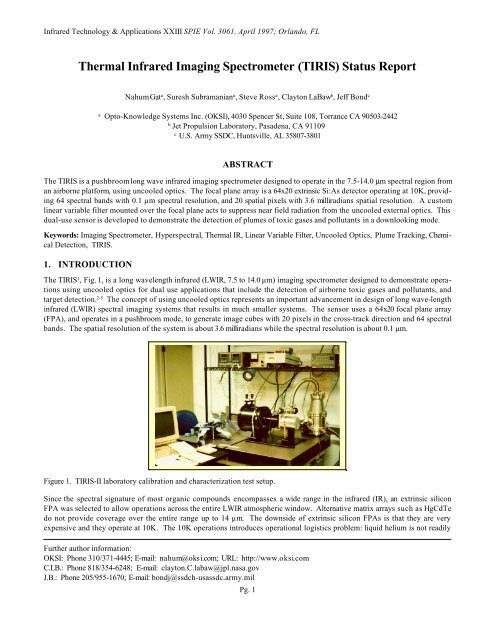
The <strong>TIRIS</strong> 1 , Fig. 1, is a long wavelength infrared (LWIR, 7.5 to 14.0 µm) imaging spectrometer designed to demonstrate operations<br />
using uncooled optics for dual use applications that include the detection of airborne toxic gases and pollutants, and<br />
target detection. 2-5 The concept of using uncooled optics represents an important advancement in design of long wave-length<br />
infrared (LWIR) spectral imaging systems that results in much smaller systems. The sensor uses a 64x20 focal plane array<br />
(FPA), and operates in a pushbroom mode, to generate image cubes with 20 pixels in the cross-track direction and 64 spectral<br />
bands. The spatial resolution of the system is about 3.6 milliradians while the spectral resolution is about 0.1 µm.<br />
Figure 1. <strong>TIRIS</strong>-II laboratory calibration and characterization test setup.<br />
Since the spectral signature of most organic compounds encompasses a wide range in the infrared (IR), an extrinsic silicon<br />
FPA was selected to allow operations across the entire LWIR atmospheric window. Alternative matrix arrays such as HgCdTe<br />
do not provide coverage over the entire range up to 14 µm. The downside of extrinsic silicon FPAs is that they are very<br />
expensive and they operate at 10K. The 10K operations introduces operational logistics problem: liquid helium is not readily<br />
Further author information:<br />
OKSI: Phone 310/371-4445; E-mail: nahum@oksi.com; URL: http://www.oksi.com<br />
C.LB.: Phone 818/354-6248; E-mail: clayton.C.labaw@jpl.nasa.gov<br />
J.B.: Phone 205/955-1670; E-mail: bondj@ssdch-usassdc.army.mil<br />
Pg. 1
<strong>Infrared</strong> Technology & Applications XXIII SPIE Vol. 3061, 1997<br />
available at all field locations from where the sensor may operate, and the use of a mechanical closed cycle cryocooler<br />
increases to overall sensor size, weight and power consumption. Since the <strong>TIRIS</strong> is expected to operate from sites where Lhe<br />
may not be readily available, the mechanical cryo-cooling approach was selected.<br />
One unique aspect of the <strong>TIRIS</strong> design approach is the use of a linearly variable filter (LVF), 6 also known as a wedge filter, to<br />
suppress near field radiation and permit operations with uncooled optics. Although LVFs are used 7 in the visible, near infrared<br />
(VNIR) and in midwave IR (MWIR), to the best of our knowledge <strong>TIRIS</strong> is the first system to adapt the LVF for the LWIR.<br />
A significant effort was invested on developing the understanding and the technology associated with building an LVF<br />
based LWIR spectrometer. This includes the manufacturing of the LVF and integrating it with the FPA. Since Si:As FPAs are<br />
not commonly used in commercial applications, the FPA drive and readout electronics were also designed from the ground up.<br />
2. SYSTEM DESIGN<br />
The <strong>TIRIS</strong> consists of a vacuum enclosure containing the cooled FPA, an optical train, control and readout electronics, a<br />
cryocooling system, and diagnostics. Table 1 summarizes key specifications of the <strong>TIRIS</strong>-I system. The required operational<br />
temperature of 10K for the FPA is achieved using a Gifford-McMahon closed cycle helium refrigerator that consists of a<br />
compressor and a two stage expander, an 80K and a 10K stage (cold finger). The two stages are rated to handle heat loads of<br />
10W (at 80K) and 1W (at 10K) respectively. The cold finger on which the FPA is mounted is enclosed in a 80K radiation<br />
shield. The vacuum enclosure uses a ZnS viewing window. Five temperature measuring sensors (Si diodes) are mounted at<br />
various locations inside the dewar to monitor the 10K and 80K stages, the inside surface of the 80K shield directly facing the<br />
FPA, and the FPA itself (a diode was epoxied in the chip cavity on the LCC and its leads wire-bonded to extra available pads).<br />
The FPA is placed in an 84 pin plastic socket and clamped to the cold finger using an Indium foil in between the ceramic<br />
carrier and the cold finger to improve heat transfer. All internal wiring use manganin leads to reduce parasitic heat load; in<br />
addition the wires are heat sunk to the cold stage. Hermetic electrical feedthrough connectors provide ample connections for<br />
all the control, signal, and diagnostics leads. Fig. 2 shows the overall layout of the <strong>TIRIS</strong> system.<br />
Table 1. Summary of <strong>TIRIS</strong>-I, a laboratory prototype, design parameters.<br />
The sensor operates at a nominal frame rate of 1,000 fps, although the pixel rate is twice as high to allow for correlated double<br />
sampling or subtractive double sampling (CDS/SDS) operations. Data are digitized to 12-bit and passed on to the computer as<br />
2 byte words. The data rate under these conditions is (1,000x2 frames/sec) x (64x20 pixels/frame) x (2 bytes/pixel) = 5.12<br />
Mbytes/sec.<br />
2.1. FPA Sensor<br />
The <strong>TIRIS</strong>-I system is based on an Aerojet PATHS 64x20 hybrid consisting of an extrinsic Si:As detector with a 100 µm unit<br />
cell size, indium bumped to a Si multiplexer readout integrated circuit (ROIC). The mux consists of two staggered 64x10<br />
p-channel MOSFETS arrays and a 6 bit gray code CMOS decoder. Each switching array is configured in 10 parallel columns<br />
Pg. 2
<strong>Infrared</strong> Technology & Applications XXIII SPIE Vol. 3061, 1997<br />
which multiplex 64 source follower buffered pixel elements per line. A unit cell diagram of the multiplexer is shown in Fig.3.<br />
The FPA is sensitive to radiation in the range 6-24 µm. 8<br />
Figure 2. Overall layout of <strong>TIRIS</strong>-I (left), sensor assembly (right).<br />
Figure 3. Unit cell diagram of FPA’s multiplex readout IC.<br />
The detector is a 64x20 Si:As device operating at 10K.<br />
Figure 4. The Aerojet PATHS FPA in <strong>TIRIS</strong>-I mounted on<br />
top of the on 10K stage<br />
2.2. Optics and Radiometry<br />
The <strong>TIRIS</strong> can function in two different pushbroom modes. First, as a slitless wedge spectrometer, and second as a dispersive<br />
spectrometer. In the former, the spectral separation is obtained solely by means of the LVF that is placed over the imaging<br />
array. In this mode, full 2-D images are grabbed in each frame. In these images, however, each cross-track strip of scene is<br />
imaged in a different “color” or spectral band. As the sensor moves forward, each strip of scene is reimaged in consecutive<br />
spectral bands (“colors”). Eventually, a full image cube is constructed. In this configuration, the foreoptics is simply a reflective<br />
telescope of any design (e.g., Cassagrain).<br />
In the dispersive mode, the foreoptics is based on 3 all reflective Schwarzchild telescopes (fig. 5). Schwarzchild telescopes are<br />
selected because they use spherical elements, are easy to fabricate and hence relatively inexpensive. They do however introduce<br />
spherical aberrations which are absent in aspherical systems . 9,10 Moreover, because of the very fast optics (~f/1), inherent<br />
to this design, focal plane curvature is present. However, for the very small FPA, the imaging quality based on simulation<br />
studies (on ZEMAX) seem satisfactory.<br />
Pg. 3
<strong>Infrared</strong> Technology & Applications XXIII SPIE Vol. 3061, 1997<br />
The first two telescopes in Fig. 5 gather and collimate radiation from the scene. These two back-to-back telescopes also focus<br />
the radiation to the entrance slit (and spatial filter) that is located at the focal plane of each. The collimated radiation is then<br />
incident on the grating which disperses it. The dispersed radiation is finally collected by a third telescope that brings it to<br />
focus on the focal plane.<br />
Figure 5. Layout and verification of imaging performance of <strong>TIRIS</strong> optics. Mirrors (M1, M2) and (M3, M4) are the first and<br />
second pairs of Schwarzschild telescopes, that collect and collimate the input beam. G is a grating whose dispersion is<br />
matched to the LVF. Mirrors (M5, M6) that form the third Schwarzschild telescope focus the image onto the focal plane. The<br />
LVF mounted directly in front of the FPA suppresses all near field thermal emissions from the optical elements.<br />
There are advantages and dis advantages for the two methods of operations. In a dispersive mode of operations the system is<br />
much more efficient in terms of utilization of all the photons received from the scene, since the grating is matched with the LVF<br />
(see next section), and the LVF suppresses the nearfield radiation from the foreoptics. Photons from nearfield or farfield that<br />
are not within the system’s field of view (FOV) are also dispersed by the grating, but are effectively blocked by the LVF (as<br />
explained in the next section). Optical efficiency is not of a major concern, however, when the system functions under<br />
background limited conditions. The photon flux in the LWIR is much higher than that required for the readout data rate of<br />
1,000 fps, in particular since the Si:As FPAs were designed to operate in a low background flux environment (i.e., looking up<br />
towards cold space rather than downlooking at the warm earth). In fact, based on radiometric calculations and laboratory<br />
calibration, the photon flux has to be attenuated by an IR neutral density filter of about ND-2.<br />
When operating as a slitless wedge spectrometer, minimum radiation is received from the nearfield optics and the suppression<br />
issue may be less important. In that case the function of the LVF is to serve as the “color” separation element. The downside<br />
of this mode is that in an airborne pushbroom operating mode, the performance of a wedge spectrometer may suffer from<br />
difficult-to-control motion of the platform (roll in particular).<br />
2.3. Linear Variable Filter (LVF)<br />
The room temperature foreoptics mounted in front of the dewar may create a condition analogous to placing a light source in<br />
the film chamber of a camera. The LVF, Fig. 6, is needed to suppress this bright source. The LVF is a multi-layer narrow band<br />
pass interference filter in which the layers of coatings have a wedge shape. The center wavelength of the LVF therefore varies<br />
depending on the position in accordance with the coating. The LVF covers the range from 7.5 to 14 µm over a length of 6.4<br />
mm (64 pixels, 0.1 mm each) thus producing a gradient of ~1 µm/mm. It is fabricated on a rectangular Si substrate whose<br />
dimensions exactly match that of the focal plane. The operating principal of the LVF is illustrated in Fig. 7a where it’s transmission<br />
is shown as a function of position. Figure 7b shows the LVF mounted about 0.2 mm over the FPA and it is cooled to<br />
~10K.<br />
Fig. 8 shows the LVF suppressing near field radiation from the foreoptics at all wavelengths. This is due to the delta like transmission<br />
property of the LVF at a particular point, where it allows only a narrow band of wavelengths to pass through and<br />
suppresses radiation at all other wavelengths. Since the grating’s dispersion is matched to the LVF’s spatial transmission<br />
characteristics, it couples external radiation very efficiently to the LVF. As a result, background thermal emissions from the<br />
Pg. 4
<strong>Infrared</strong> Technology & Applications XXIII SPIE Vol. 3061, 1997<br />
optical elements in each of the LVF’s transmission windows becomes negligible compared to the signal. We note that the LVF<br />
itself starts to transmit radiation above 15 mm but it does not transmit below 7.5 mm. Since the FPA is sensitive up to 24 mm, a<br />
ZnS filter is place directly above the LVF to provide total out of band blockage of radiation.<br />
In order to match the grating’s dispersion the LVF transmission curve slightly deviates from linear as indicated in Fig. 9. Exact<br />
positioning of the LVF relative to the FPA pixels , both in translation and rotation, is therefore critical. No provision is available<br />
on <strong>TIRIS</strong>-I system to micro adjust the LVF position relative to FPA once the dewar is closed. However, the second<br />
generation <strong>TIRIS</strong>-II system has two micrometer adjustments that can be manipulated from outside the dewar, to align the LVF<br />
exactly with the focal plane. These micrometers have mechanical feed throughs that extend through the vacuum shroud and<br />
radiation sheilds and provide both translational as well as a rotational capability.<br />
Figure 6. The LVF -- about 6.4 mm x 2 mm in size, is bonded to a Si frame for mounting purposes.<br />
Figure 7. LVF operating concept. (a) shows the LVF’s transmission<br />
function varying linearly with position from 7.5 µm<br />
at one end to 14 µm at the other. (b) side and top view of the<br />
LVF placed 0.2 mm over the FPA.<br />
Figure 8. Suppression by the LVF of out-of-band near field<br />
thermal radiation emitted by the foreoptics.<br />
2.4. Electronics<br />
The <strong>TIRIS</strong> sensor and electronics are controlled by a PC which also contains a frame grabber to acquire data from the FPA.<br />
The entire electronics to operate the FPA and interface it to the frame grabber was custom designed, Fig.10.<br />
The PC communicates with the focal plane electronics via a parallel I/O interface. All the clock rails and bias levels required to<br />
operate the FPA are generated using DACs. The timing patterns to operate the focal plane are loaded into an FPGA from a<br />
PROM. The PROM also provides the FPGA with the necessary frame grabber timings such as the pixel, line and frame validation<br />
clocks. Pixel readout is software controlled. A gray code is required to sequentially address a row of pixels from 1 to 64.<br />
Alternative readout procedures are possible by modifying the addressing scheme. At present, the parallel interface provides<br />
Pg. 5
<strong>Infrared</strong> Technology & Applications XXIII SPIE Vol. 3061, 1997<br />
the user full control over the clock and bias level settings and the readout scheme. However, the FPA and frame grabber<br />
timing patterns can be modified only by replacing the PROM. A future EEPROM based design will permit modification of<br />
timing patterns also from the computer.<br />
To allow noise reduction via correlated double sampling (CDS) or subtractive double sampling (SDS), each row is read twice,<br />
once after incrementing the gray code, and a second time after a reset signal is applied to the row. Data are read in 20 parallel<br />
channels corresponding to the FPA's 20 columns. Each channel leads to an analog chain where suitable gains and offsets are<br />
applied to the data so as to fully utilize the entire dynamic range of the A/D converters. Every three data channels are then<br />
multiplexed to a single A/D converter. Seven ADCs are used to digitize all 20 columns of pixels at 12-bit resolution. As a<br />
result, we obtain 7x3 = 21 columns of data from the focal plane. The last column does not contain real data and is an artifact of<br />
the multiplex readout process. Each A/D converter is then sequentially given access to a bus that is connected to the frame<br />
grabber. CDS or SDS are then performed in software.<br />
Figure 9. The LVF’s transmission function is matched to the grating’s dispersion.<br />
Figure 10. Prototype <strong>TIRIS</strong>-I electronics.<br />
3. <strong>TIRIS</strong>-II DESIGN<br />
<strong>TIRIS</strong>-II is the second generation LWIR imaging spectrometer design based on lessons from <strong>TIRIS</strong>-I laboratory prototype.<br />
The primary areas of improvement are as follows:<br />
• The FPA was switched from the older generation PATHS to a newer HYWAYS Si:As device, made by Hughes, that is<br />
also based on a 64x20 architecture.<br />
Pg. 6
<strong>Infrared</strong> Technology & Applications XXIII SPIE Vol. 3061, 1997<br />
• The dewar was redesigned to afford more flexibility and enhanced performance: (i) a 10K radiation shield was added in<br />
addition to the 80K shield, (ii) an 8-position, 10K cold filter wheel was added to allow the insertion of band pass filters, ND<br />
filters, pinholes, or a blank for the purpose of testing, calibration 11 and characterization (Fig. 11), (iii) Two micrometer<br />
feedthrough were incorporated to allow full control for the adjustment of the LVF in both translation and rotation, to<br />
completely register it with the FPA pixels (This fine alignment is needed for the proper positioning after the thermal<br />
contraction of various components during cool down to 10K), Fig 12.<br />
• A larger cryocooler was installed with a capacity of about 3 Watt at 10K. This was necessary because of the various<br />
feedthroughs incorporated into the dewar for LVF and filter wheel control, which increase the overall heat load.<br />
• The electronics design for FPA control/data acquisition have been extensively redesigned. The <strong>TIRIS</strong>-I goal was to test<br />
and evaluate various design approaches. With <strong>TIRIS</strong>-II the goal is to refine and produce the highest quality possible<br />
signal to noise ratio.<br />
Figure 11. Filter wheel mounted onto the 10K radiation shield (shown in open position above the LVF holder and FPA).<br />
To this end, care has been taken to keep all the bias and data lines isolated from the clock lines until they are brought together<br />
at the focal plane. The manganin wires carrying signals and data in <strong>TIRIS</strong>-I have been replaced by micro-coaxial cables with<br />
the sheaths grounded. This feature significantly reduces noise and cross talk between digital clocks and analog signals. All<br />
analog and digital circuitry have been completely isolated and the only point of contact between the two is at the A/D<br />
converters. Instead of 7 A/D converters used in a 3-1 multiplex mode, 20 parallel 12 bit flash A/D converters are used to digitize<br />
the data. The timing patterns have been carefully adjusted so that no clocks switching occurs when the A/D converters<br />
digitize the data. All clock signals have been filtered so that they now resemble rounded trapezoids. This minimizes high<br />
frequency noise produced by clock ringing. All clock lines have also been suitably terminated to minimize ringing. The<br />
analog chain that gains and offsets the data before passing it on the A/D converters also filter the data with a rapid roll-off at a<br />
frequency of twice the pixel clock rate. The current data rate is set at 1000 frames per second. A prototype design of the<br />
electronics hardware has yielded noise levels < 1 mV. CDS is performed in software while SDS can be performed directly in<br />
hardware. We anticipate that the final system will have noise levels of the order of a few 100 µV resulting in a field operating<br />
system with at least 10 bit dynamic range.<br />
Pg. 7
<strong>Infrared</strong> Technology & Applications XXIII SPIE Vol. 3061, 1997<br />
Figure 12. <strong>TIRIS</strong>-II system. HYWAYS FPA in sensor (right) and LVF holder with manipulator levers (left).<br />
4. APPLICATIONS<br />
Most molecules possess spectral features in the IR that can be used for their detection and identification. As mentioned at<br />
the beginning of this paper, one of <strong>TIRIS</strong>’s applications is the detection of organic compound and plumes in the atmosphere.<br />
These may be related to pollutants, chemical warfare agents, drug manufacturing byproducts, volcanic plumes and much more.<br />
Some description of an algorithmic approach to signal processing is given in another paper presented in this SPIE<br />
conference. 12 In addition, IR imagery also has broad applications in land management use, target detection, the tracking of<br />
thermal plumes discharged into water bodies from cooling towers of power plants, etc. Some discussion of algorithmic<br />
techniques for classification can be found in ref. 13.<br />
5. SUMMARY<br />
This Paper outlined the status of the <strong>TIRIS</strong> system which is the first demonstration of the use of uncooled optics in a LWIR<br />
imaging spectrometer. <strong>TIRIS</strong> is currently undergoing laboratory characterization and calibration. In addition, laboratory<br />
measurements of gas detection are also underway. Finally the algorithmic basis is also under development.<br />
Additional background and updates to this work can be found on the WWW. 14<br />
ACKNOWLEDGMENTS<br />
The work in this paper has been performed under DARPA contract # DASG60-94-C-0088. The FPA was provided by the<br />
USAF Phillips Laboratories.<br />
REFERENCES<br />
1. C. Mahoney et al, “<strong>Thermal</strong> <strong>Infrared</strong> <strong>Imaging</strong> <strong>Spectrometer</strong>: An advanced optics technology instrument,” SPIE Vol. 1298,<br />
<strong>Imaging</strong> Spectroscopy of the Terrestrial Environment, (1990).<br />
2. N. Gat, S. Subramanian, J. Barhen, N. Toomarian, N. "Spectral <strong>Imaging</strong> Applications: Remote Sensing, Environmental<br />
Monitoring, Medicine, Military operations, factory Automation and Manufacturing," SPIE Vol. 2962, (1996).<br />
3. W.B. Grant, R.H. Kagann, W.A. McClenny, “Optical remote measurements of toxic gases,” Journal of Air Waste<br />
Manag. Assc., Vol. 42, 19, (1992).<br />
4. R.L. Spellicy et al, “Spectroscopic remote sensing addressing requirements of the clean air act,” Spectroscopy, Vol. 6,<br />
Nov/Dec., (1991).<br />
5. M. Crawford, Air Pollution Control Theory, McGraw Hill, (1976).<br />
6. C. LaBaw, “Integrated Filter and Detector Array for Spectral <strong>Imaging</strong>,” U.S. Patent # 5,159,199.<br />
N. Gat, “<strong>Spectrometer</strong> Apparatus”, U.S. Patent # 5, 166, 755, (1992).<br />
Pg. 8
<strong>Infrared</strong> Technology & Applications XXIII SPIE Vol. 3061, 1997<br />
7. A.M. Mika “Linear Wedge <strong>Spectrometer</strong>,” SPIE Vol. 1298, <strong>Imaging</strong> Spectroscopy of the Terrestrial Environment, (1990).<br />
8. W.D. Rogatto, editor, The <strong>Infrared</strong> and Electro-Optical Systems Handbook, Vol. 3, SPIE/ERIM Press, (1993).<br />
9. D.J. Schroeder, Astronomical Optics, Academic Press, (1987).<br />
10. D. Korsch, Reflective Optics, Academic Press, (1991).<br />
11. C.L. Wyatt, Radiometric System Design, MacMillan, (1987)<br />
12. N. Gat,et-al, “Cemical Detection Using the Airborne <strong>Thermal</strong> <strong>Infrared</strong> <strong>Imaging</strong> <strong>Spectrometer</strong> (<strong>TIRIS</strong>),” in Electro-Optical<br />
technology for Remote Chemical Detection and Identification II, SPIE Vol. 3082, 1997.<br />
13 S. Subramanian, et-al “Methodology for hyperspectral image classification using novel neural network,” in Algorithms<br />
for Multispectral and Hyperspectral Imagery III, SPIE Vol. 3071, 1997.<br />
14. Recent development and expanded coverage can be found on the WWW at http://www.techexpo.com/opto-knowledge.<br />
Pg. 9