
Create successful ePaper yourself
Turn your PDF publications into a flip-book with our unique Google optimized e-Paper software.
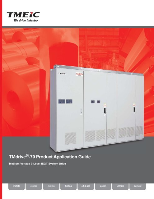
<strong>TMdrive</strong> ® -<strong>70</strong> Product <strong>Application</strong> <strong>Guide</strong><br />
Medium Voltage 3-Level IEGT System Drive<br />
metals<br />
cranes<br />
mining<br />
testing<br />
oil & gas<br />
paper<br />
utilities<br />
cement
AC<br />
AC<br />
AC<br />
AC<br />
AC<br />
AC<br />
AC<br />
AC<br />
Local Monitoring/Control/Analysis<br />
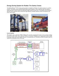
The family of <strong>TMdrive</strong> ® ac system<br />
drives is targeting specific<br />
customer requirements for:<br />
Ethernet<br />
MELPLAC<br />
Controllers<br />
Innovation Series Controller (ISC)<br />
V<br />
Vseries Controller<br />
V Series Controller<br />
• High reliability<br />
• Simple configuration and maintenance<br />
• Low cost of ownership<br />
MELPLAC Net<br />
<strong>TMdrive</strong><br />
MELVEC<br />
ISBus<br />
DLAN+<br />
Profibus-DP<br />
<strong>TMdrive</strong><br />
TOSVERT<br />
TOSLINE-S20<br />
Series Six Parallel I/O Bus<br />
Genius ®<br />
Field<br />
Control I/O<br />
Genius ® I/O<br />
Block<br />
VersaMax ®<br />
TOSLINE-S20<br />
V<br />
<strong>TMdrive</strong><br />
LEOPACK<br />
Vseries I/O<br />
V Series I/O<br />
TOSVERT<br />
Installed I/O<br />
and Drives<br />
LEOPACK<br />
LV<br />
• Series Six I/O<br />
• DIRECTO-MATIC ® Plus I/O<br />
• DIRECTO-MATIC Controller<br />
• Digital Siltron Drives<br />
MV<br />
Legacy Drive Products<br />
DC2000<br />
IEGT Technology Dramatically Lowers Cost of Ownership<br />
The Injection Enhanced Gate Transistor (IEGT) is a breakthrough in power switch<br />
technology. The following set of features and associated benefits details how this<br />
device lowers your cost of ownership versus previous main drive technology.<br />
Features<br />
• Low Voltage Gate Drive<br />
Given that the IEGT is a MOS<br />
structure, it can be gated<br />
(turned on/off) with ±15 V.<br />
• Minimal Snubber Circuitry<br />
With the high dV/dt capability of<br />
the IEGT, there is only need for a<br />
small dc clamp snubber circuit.<br />
• High-Speed Switching<br />
The IEGT is switched at a rate of<br />
500 Hz in this application.<br />
Benefits<br />
• High Efficiency and Small Size<br />
A very <strong>com</strong>pact phase leg assembly is achieved with:<br />
• A reduction in snubber circuitry<br />
• Integral forward diodes<br />
• Integral clamp diodes<br />
• Higher Performance<br />
The reduction in snubber circuitry allows a higher<br />
chopping frequency, lowering the torque ripple<br />
applied to the motor and harmonics fed back into<br />
the power system.<br />
• Motor and Power System Friendly<br />
The high-speed switching coupled with the threelevel<br />
power bridge design delivers a smooth sine<br />
wave to the motor and power system.<br />
2
Bringing Reliable Control<br />
To System <strong>Application</strong>s<br />
High-power, precision-controlled processes<br />
are ideally suited for the <strong>TMdrive</strong>-<strong>70</strong><br />
with its efficient high current IEGT power<br />
devices and control cards <strong>com</strong>mon to<br />
the drive family. Flexible arrangement of<br />
converter, inverter and cooling units allows<br />
for maximum power density, resulting in<br />
minimum floor space, and installation cost.<br />
Coordinated drive systems are an integral part<br />
of numerous manufacturing processes in the<br />
metals industry. <strong>TMdrive</strong> system drives address<br />
all of these applications with a robust control<br />
platform and a <strong>com</strong>mon Microsoft Windowsbased<br />
tool. The tool supports local and remote<br />
connectivity, and is an invaluable asset for<br />
system and process analysis.<br />
Due to its high reliability, simplicity of design and high<br />
efficiency, the <strong>TMdrive</strong>-<strong>70</strong> is perfect for <strong>com</strong>pressor, fan<br />
and pumping applications. It provides accurate speed<br />
control and high efficiency while eliminating the need<br />
for high maintenance mechanical flow control devices.<br />
The <strong>TMdrive</strong>-<strong>70</strong> is also well suited for applications like<br />
grinding mills and mine hoists, where high overloads<br />
and impacts are a part of everyday operations.<br />
3
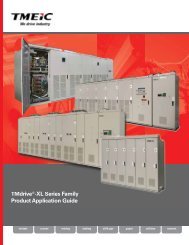
A Look Inside<br />
State-of-the-Art Technology:<br />
• Injection Enhanced Gate<br />
Transistor (IEGT)-based<br />
converter and inverter<br />
provides power to the process<br />
at near unity power factor with<br />
minimum harmonic distortion<br />
• Water-cooling technology<br />
for the power bridge reduces the<br />
footprint of the equipment saving<br />
valuable space in your factory<br />
• Modular design for power<br />
bridge minimizes the time<br />
required for any maintenance<br />
activities<br />
Control Cabinet<br />
Converter Front View<br />
Control Functions<br />
Each inverter<br />
and regenerative<br />
converter shares a<br />
<strong>com</strong>mon set<br />
of control boards. The primary<br />
control board performs several<br />
functions:<br />
• Speed and torque regulation<br />
• Sequencing<br />
• I/O mapping<br />
• Diagnostic data gathering<br />
A mounting bracket is provided for<br />
an optional LAN interface board.<br />
I/O Board<br />
The I/O board<br />
supports encoder or<br />
resolver, 24 V dc I/O,<br />
115 V ac inputs and analog I/O,<br />
standard. All I/O are terminated<br />
to a two-piece modular terminal<br />
block for ease of maintenance.<br />
IEGT Three-Level Phase Leg Assembly<br />
The drive has a total of six identical Injection Enhanced Gate<br />
Transistor (IEGT) phase leg assemblies in the converter and inverter.<br />
The modular draw-out assembly includes:<br />
• Four IEGT power semiconductors with integrated flyback diodes<br />
• Neutral-point clamp diodes<br />
• Water-cooled piping assembly with quick disconnect fittings<br />
• IEGT gate driver circuit board<br />
• Feedback control circuitry<br />
• dc clamp snubber mounted on top<br />
4
Inverter Front View<br />
Optional Remote Control<br />
Modular construction allows<br />
the power converter and<br />
control cabinets to be installed<br />
up to 150 m (500 ft) apart.<br />
This optimizes the use of space in your<br />
equipment room.<br />
dc Bus<br />
The converter generates dc power for<br />
NP<br />
the inverter. The inverter then creates<br />
variable frequency ac power to<br />
control the induction or synchronous<br />
motor. The dc power between the converter<br />
and inverter is conveyed on a solid copper<br />
bus behind the phase leg assemblies in both<br />
cabinets. For <strong>com</strong>mon bus systems this bus is<br />
extended to adjacent cases.<br />
Inverter Back View<br />
Converter Back View<br />
Output<br />
Voltage<br />
Output<br />
Current<br />
Main Capacitors<br />
Oil filled dc capacitors<br />
are used to provide<br />
long life under all<br />
service conditions and<br />
duty cycles.<br />
Main Power<br />
3-Phase motor and<br />
transformer are made in<br />
the rear. Both top and<br />
bottom e supported.<br />
Cooling Water Interface<br />
150 mm JIS-10K50A fittings are<br />
provided for connecting cooling water<br />
for de-ionized cooling loop. Water<br />
interface shown here is for “separate”<br />
type water conditioner.<br />
5
<strong>TMdrive</strong>-<br />
Flexible Topologies To Match Your Needs<br />
<strong>TMdrive</strong>–<strong>70</strong> IEGT Inverter<br />
8000 Frame<br />
10000 Frame<br />
Configuration Options<br />
1 Bank Converter<br />
1 Bank Inverter<br />
High Speed<br />
Fuses<br />
Discharge<br />
Resistors<br />
2430 V dc<br />
Motor Current<br />
Sensor<br />
<strong>TMdrive</strong>-P<strong>70</strong><br />
2430 V dc<br />
4 Bank Converter<br />
4 Bank Inverter<br />
<strong>TMdrive</strong>–P<strong>70</strong> Regenerative IEGT Converter<br />
8000 Frame<br />
10000 Frame<br />
<strong>TMdrive</strong>-P<strong>70</strong><br />
+<br />
Circuit<br />
Breaker<br />
3550 V ac<br />
2430 V dc<br />
NP<br />
<strong>TMdrive</strong>-<br />
2430 V dc<br />
Control<br />
-<br />
<strong>TMdrive</strong>-P<strong>70</strong><br />
380/440/460 V ac<br />
Initial Charging<br />
Circuit<br />
System<br />
Ground<br />
6
1 Bank Converter<br />
2x1 Bank Inverter<br />
M<br />
M<br />
<strong>TMdrive</strong>-<strong>70</strong><br />
<strong>TMdrive</strong>-P<strong>70</strong><br />
<strong>TMdrive</strong>-<strong>70</strong><br />
M<br />
<strong>TMdrive</strong>-<strong>70</strong><br />
2 Bank Converter<br />
2 Bank Inverter<br />
<strong>TMdrive</strong>-D/P<strong>70</strong><br />
-P<strong>70</strong><br />
<strong>TMdrive</strong>-<strong>70</strong><br />
M<br />
<strong>TMdrive</strong>-<strong>70</strong><br />
<strong>TMdrive</strong>-P<strong>70</strong><br />
<strong>TMdrive</strong>-<strong>70</strong><br />
<strong>TMdrive</strong>-<strong>70</strong><br />
M<br />
2 Bank Converter<br />
3x1 Bank Inverter<br />
-P<strong>70</strong><br />
<strong>TMdrive</strong>-<strong>70</strong><br />
M<br />
<strong>TMdrive</strong>-P<strong>70</strong><br />
<strong>TMdrive</strong>-<strong>70</strong><br />
M<br />
<strong>TMdrive</strong>-<strong>70</strong><br />
<strong>TMdrive</strong>-<strong>70</strong><br />
<strong>TMdrive</strong>-P<strong>70</strong><br />
M<br />
<strong>TMdrive</strong>-<strong>70</strong><br />
7
Regenerative Systems<br />
AC<br />
Three-Level Phase Leg Assembly for Both Converter and Inverter<br />
High Speed<br />
Fuses<br />
Quick disconnect<br />
fittings for the<br />
cooling system<br />
reduces mean<br />
time to repair<br />
Discharge<br />
Resistors<br />
2430 V dc<br />
2430 V dc<br />
Motor Current<br />
Sensor<br />
Compact gate<br />
driver assemblies<br />
due to low<br />
power switching<br />
requirements of<br />
the IEGT devices<br />
2375 mm (94 in)<br />
2375 mm (94 in)<br />
2375 mm (94 in)<br />
2375 mm (94 in)<br />
8<br />
Control Cabinet Depth: <strong>70</strong>0 mm (28 in)<br />
IEGT devices with integral forward and<br />
clamp diodes allow a very <strong>com</strong>pact phase<br />
leg stack, reducing the footprint versus<br />
previous technology<br />
Width: 3200 mm (126 in) Depth: 1650 mm (65 in)<br />
Control Cabinet Depth: <strong>70</strong>0 mm (28 in)<br />
Width: 5600 mm (220 in) Depth: 1650 mm (65 in)<br />
Control Cabinet Depth: <strong>70</strong>0 mm (28 in)<br />
Width: 6400 mm (252 in) Depth: 1650 mm (65 in)<br />
Width: 4800 mm<br />
(189 in)<br />
Depth: 1650 mm<br />
(65 in)<br />
dc clamp snubber circuit used to absorb the<br />
energy generated in turning off the IEGTs<br />
Banks<br />
1<br />
2<br />
4<br />
Frame<br />
8000<br />
Weight<br />
kg (lbs)<br />
4900<br />
(10780)<br />
10000 5200<br />
(11440)<br />
16000 9500<br />
(20900)<br />
20000 10200<br />
(224400)<br />
32000 19000<br />
(41800)<br />
40000 20300<br />
(44660)<br />
Control<br />
Power<br />
kVA<br />
3.8<br />
3.8<br />
7.2<br />
7.2<br />
14.3<br />
14.3<br />
Motor<br />
Current<br />
A ac<br />
Allowable<br />
Overload<br />
%<br />
1360 150<br />
1166 175<br />
1020 200<br />
907 225<br />
816 250<br />
1<strong>70</strong>0 150<br />
1457 175<br />
1275 200<br />
1133 225<br />
1020 250<br />
2720 150<br />
2331 175<br />
2040 200<br />
1813 225<br />
1632 250<br />
3400 150<br />
2914 175<br />
2550 200<br />
2267 225<br />
2040 250<br />
5440 150<br />
4663 175<br />
4080 200<br />
3627 225<br />
3264 250<br />
6800 150<br />
5829 175<br />
5100 200<br />
4533 225<br />
4080 250
AC<br />
Environmental (Inverters and Converters)<br />
Mechanical (Inverters and Converters)<br />
Operating Air<br />
Temperature<br />
Storage Temperature<br />
Humidity<br />
Altitude<br />
Vibration<br />
Operating Water<br />
Temperature<br />
0 to 40°C (32 to 104°F) at rated load<br />
0 to 50°C (32 to 122°F) with derating<br />
-20 to 55°C (-13 to 131°F)<br />
5 to 95% relative humidity<br />
Non-condensing<br />
0 to 1000 m above sea level<br />
10-50 Hz,
Water Conditioning Equipment<br />
Power Bridge<br />
Power Converter Panel<br />
Power Bridge<br />
Power Converter<br />
Panel(s)<br />
Water conditioning control panel<br />
continuously monitors the status of<br />
the water system. Separate fault<br />
indications help find and fix<br />
problems fast.<br />
Water<br />
Panel<br />
Integrated water system has internal<br />
plumbing for de-ionized cooling loop.<br />
Water<br />
Panel<br />
Separate type cooling has field-installed<br />
plumbing for de-ionized cooling loop.<br />
Water to water heat<br />
exchanger keeps the<br />
de-ionized system<br />
isolated from the plant<br />
water supply.<br />
Surge tank absorbs<br />
water during pump<br />
transients and<br />
indicates the internal<br />
cooling loop water<br />
level.<br />
De-ionizer removes<br />
contaminants for the<br />
internal cooling loop.<br />
Redundant pumps<br />
keep the system<br />
running even if one<br />
pump fails<br />
Type<br />
Capacity<br />
Width<br />
mm (in)<br />
Depth<br />
mm (in)<br />
Height<br />
mm (in)<br />
Weight<br />
kg (lbs)<br />
kVA<br />
Notes<br />
Integrated with<br />
Lineup<br />
125 kW<br />
1200<br />
(48)<br />
1650<br />
(65)<br />
2375<br />
(94)<br />
1600<br />
(3527)<br />
5<br />
Capacity for one converter/inverter, (1 bank)<br />
Plant water required: 300 l/min (80 gal/min)<br />
Separate<br />
Cabinet<br />
250 kW<br />
1200<br />
(48)<br />
2000<br />
(79)<br />
2500<br />
(99)<br />
1650<br />
(3638)<br />
10<br />
Capacity for two converters/inverters, (2 bank)<br />
Plant water required: 600 l/min (160 gal/min)<br />
Separate<br />
Cabinet<br />
500 kW 3000<br />
(118)<br />
2000<br />
(79)<br />
2500<br />
(99)<br />
2650<br />
(5842) 15<br />
Plant water required: 1200 l/min (4 bank)<br />
(320 gal/min)<br />
Separate<br />
Cabinet<br />
750 kW 4300<br />
(1<strong>70</strong>)<br />
2000<br />
(79)<br />
2500<br />
(99)<br />
4300<br />
(9480) 25<br />
Plant water required: 1800 l/min (6 bank)<br />
(475 gal/min)<br />
Advanced PWM Technology<br />
Advanced PWM control brings enhanced efficiency and reduced harmonics to <strong>TMdrive</strong>-<strong>70</strong> systems. Fixed pulse pattern<br />
gate control uses optimum gating sequences to almost eliminate switching losses in the IEGT device. Gating sequences are<br />
pre-<strong>com</strong>puted for the control rather than <strong>com</strong>puted at runtime. The result is performance that reduces losses and harmonics.<br />
Input Current<br />
Diode Current<br />
IEGT Current<br />
Output Voltage<br />
10<br />
Conventional PWM<br />
Fixed Pulse Pattern Control
Field Supply Specifications<br />
2375 mm (94 in)<br />
800 mm (32 in)<br />
Depth: 950 mm (37 in)<br />
2375 mm (94 in)<br />
Type<br />
1200 A<br />
2100 A<br />
1200 mm (47 in)<br />
Depth: 950 mm (37 in)<br />
Overload<br />
Time<br />
(sec)<br />
Frame<br />
1200<br />
2100<br />
Weight<br />
kg (lbs)<br />
300<br />
(660)<br />
<strong>70</strong>0<br />
(1540)<br />
Control<br />
Power<br />
KVA<br />
Field Exciter Continuous Current Rating, dc Amps<br />
50 HZ 60 HZ<br />
AC Leg Fuses<br />
protect power<br />
bridge from<br />
faults on the<br />
ac line<br />
Autonomous<br />
Crowbar<br />
prevents<br />
dangerous<br />
motor<br />
voltages from<br />
developing<br />
under certain<br />
fault conditions<br />
150% 175% 200% 225% 250% 300% 150% 175% 200% 225% 250% 300%<br />
10 1320 1200 1100 1010 940 810 1360 1240 1130 1040 960 830<br />
30 1230 1100 1000 900 820 710 1280 1130 1020 915 845 720<br />
60 1180 1040 920 830 760 645 1205 1060 945 850 775 660<br />
120 1120 980 860 760 690 585 1160 1000 885 790 710 590<br />
10 2376 2160 1980 1818 1692 1458 2448 2232 2034 1872 1728 1494<br />
30 2214 1980 1800 1620 1476 1278 2304 2034 1836 1647 1521 1296<br />
60 2124 1872 1656 1494 1368 1161 2169 1908 1<strong>70</strong>1 1530 1395 1188<br />
120 2016 1764 1548 1368 1242 1053 2088 1800 1593 1422 1278 1062<br />
0.5<br />
0.5<br />
Voltage<br />
Vac<br />
(Vdc)<br />
500<br />
(675)<br />
500<br />
(675)<br />
2100 Frame Field Supply<br />
DC Field<br />
Connection Bus<br />
Main Power<br />
module. One<br />
module is<br />
applied for<br />
the 1200A<br />
supply and<br />
two modules<br />
for the 2100A<br />
model.<br />
Ground Fault<br />
detection<br />
module<br />
provides<br />
indication<br />
of insulation<br />
failure<br />
AC Connection Bus. AC<br />
voltages up to 500 Vac can<br />
be connected depending<br />
on<br />
required voltage<br />
Enhanced Converter Technology<br />
<strong>TMdrive</strong>-P<strong>70</strong> VAR Control<br />
The <strong>TMdrive</strong>-P<strong>70</strong> converter can be configured in two modes, providing<br />
VAR Control within the limits of its current capacity.<br />
One mode is the conventional PWM type normally set to hold<br />
unity power factor for all load conditions. (Shown in red)<br />
Another mode is the Fixed Pattern type, providing voltage stability,<br />
improved harmonics and efficiency. The Fixed Pattern mode stabilizes<br />
line voltage by providing system VARs when line voltage is low and<br />
drawing VARs from the system when the voltage is high. By convention,<br />
VARs from the system are (+) and cause the line voltage to drop while<br />
VARs from the converter are (-) and cause the line voltage to rise. The<br />
relationship of line voltage, loads MW and converter MVAR is shown by<br />
the blue voltage lines depending on the measured line voltage.<br />
MVA vs. MW and Voltage<br />
11
<strong>Application</strong> Examples<br />
Applying the <strong>TMdrive</strong>-<strong>70</strong> Starts With the Motor Design<br />
Consideration must be given to motor design when applying the <strong>TMdrive</strong>-<strong>70</strong>. A primary constraint is the motor terminal voltage. It is<br />
important that the motor terminal voltage does not exceed 3400Vac under any operating condition. Reserving voltage margin correctly<br />
is critical to success. Detailed motor design data is needed for correct application.<br />
OL_V<br />
Overload derate. The rated motor voltage over the<br />
terminal voltage of the motor at maximum applied<br />
overload. Motors with no overload use 1.0.<br />
ST_V<br />
Field forcing margin needed when applying<br />
synchronous motors. Apply 0.94 for synchronous motor<br />
systems.<br />
RP_V<br />
Reduction in maximum voltage due to the dc bus ripple<br />
of the drive at low frequencies. If the base frequency is<br />
below 5 Hz then this derate is 0.97, otherwise it is 1.0.<br />
SP_V<br />
Speed margin. For motors that run above base speed<br />
this is the ratio of the terminal voltage at base speed<br />
over the terminal voltage at top speed under maximum<br />
overload at each point. Other motors use 1.0.<br />
Maximum Rated Motor Voltage = 3400 x OL_V x RP_V x ST_V x SP_V<br />
Experience has shown that the following maximum rated motor voltages apply based on the type of motor<br />
and the application.<br />
Induction<br />
Synchronous<br />
Rated Motor<br />
Overload<br />
Example<br />
(Maximum Voltage at max OL<br />
Maximum Rated Motor Volts Frequency<br />
Requirement<br />
<strong>Application</strong><br />
and top speed)<br />
3400 3300 60 Hz 100% Pump or Fan<br />
3300 3200 30 Hz 200% Mine Hoist<br />
3200 3100 5 Hz 225% Mill Stand<br />
<strong>TMdrive</strong>-<strong>70</strong> Notes<br />
1. Power bridge cabinets are 1650 mm (65in) in depth.<br />
Control cabinets are <strong>70</strong>0 mm (28 in) in depth. Dimensions<br />
do not include required 50 mm (2 in) channel base.<br />
2. Allocate a minimum of 550 mm (20 in) above cabinet for<br />
fan maintenance.<br />
3. Power rating data assumes ambient temperature of<br />
0-40 ˚C (32-104 ˚F), altitude up to 1000 m (3280 ft) above<br />
sea level.<br />
4. The specified current ratings are continuous to which the<br />
indicated overload may be applied for a maximum of 60<br />
seconds.<br />
5. Each cabinet requires 3-phase control power.<br />
6. For high performance torque regulation, a temperature<br />
sensor is mounted in the motor.<br />
7. All <strong>TMdrive</strong>-<strong>70</strong> cabinets require 1000 mm (40 in) back<br />
access for connections and maintenance.<br />
8. Speed and current regulator responses are <strong>com</strong>puted<br />
per the adjacent figure in radians/s. Speed regulator<br />
responses shown are maximum available. Actual response<br />
will be limited by drive train mechanical conditions.<br />
Accuracy and linearity specifications shown are as<br />
measured under controlled conditions in our lab and while<br />
typical may not be achievable in all systems.<br />
12<br />
9. Water connections for separate<br />
type cooling systems are located<br />
near the floor in the rear of power<br />
converter cabinets. The flange is<br />
1500 mm JIS-10K50A. Stainless<br />
piping is required for plumbing of<br />
the de-ionized loop.<br />
10. dc Bus bar included in lineups is<br />
rated for one inverter only. For<br />
<strong>com</strong>mon bus systems, converters<br />
Step Response<br />
Response at 95%<br />
of final value<br />
and inverters are arranged so that this limitation<br />
is not exceeded.<br />
11. When output or input reactors are used to parallel systems<br />
then the dc Buses of those systems must be connected<br />
together.<br />
12. Systems that share a <strong>com</strong>mon dc Bus must have the<br />
same winding configuration for their converter transformer<br />
secondaries.<br />
13. Field supply enclosures are typically installed directly<br />
behind control enclosures within the lineup.<br />
14. <strong>TMdrive</strong>-D<strong>70</strong> converters require a minimum of 10% total<br />
input impedance. <strong>TMdrive</strong>-P<strong>70</strong> converters require a<br />
minimum of 15% total input impedance.<br />
15. Systems with a base frequency below 5 Hz may<br />
require additional 800 mm (32 in) capacitor panels<br />
for each dc link.<br />
1<br />
T 95%<br />
includes<br />
response latency<br />
Time<br />
T 95%<br />
Response = 3/T<br />
95% (radians/s)
Inverter Example<br />
When specifying an inverter, start from the process requirements and work through the motor to the inverter.<br />
The following example illustrates this process.<br />
1<br />
Define process<br />
requirements.<br />
2<br />
Select motor based on process<br />
requirements and <strong>com</strong>pute<br />
required inverter kVA.<br />
• 6500 kW (8<strong>70</strong>0 hp)<br />
• 500 rpm, 3100 V<br />
• Efficiency = 0.965<br />
• Power factor = 1.00<br />
• Service factor = 1.0<br />
• Synchronous<br />
3<br />
Compute continuous<br />
current requirements for<br />
the inverter based on<br />
the selected motor.<br />
4<br />
Select inverter based on<br />
continuous current and<br />
overload requirements.<br />
Scan the 150% entries in the<br />
inverter tables for a frame where<br />
the continuous current rating<br />
exceeds 1234 amps.<br />
The 8000 frame meets this<br />
criterion (1360 amps) and is<br />
appropriate for this application.<br />
kW Shaft = 6500 kW (8<strong>70</strong>0 hp)<br />
500 rpm<br />
The motor delivers constant torque from<br />
zero to base speed of 500 rpm and 6500<br />
kW (8<strong>70</strong>0 hp).<br />
Duty cycle requires 150% for 10 sec. but has<br />
rms duty cycle of 6500 kW (8<strong>70</strong>0 hp).<br />
I ac Inverter =<br />
kW Shaft x 1000 x SF Mtr<br />
3 x V Motor rated voltage x Eff Mtr x PF Mtr<br />
= 6500 x 1000 x 1.0<br />
3 x 3150 V x 0.965 x 1.0<br />
= 1234 amps<br />
Current<br />
A ac<br />
1360<br />
1166<br />
1020<br />
907<br />
816<br />
Allowable<br />
Overload %<br />
150<br />
175<br />
200<br />
225<br />
250<br />
Regenerative Converter (<strong>TMdrive</strong>-<strong>70</strong>) Example<br />
When specifying a converter, start from the process requirements and work through the motor to the inverter, and then the<br />
associated converter. The following example illustrates this process (continuation of inverter application example from above):<br />
1 Compute kW requirements<br />
into the inverter. It is<br />
assumed that the converter<br />
is dedicated to the inverter<br />
specified in the application<br />
example above.<br />
It is also assumed that the<br />
converter is controlled to unity<br />
power factor.<br />
kW ac<br />
2<br />
I ac Converter<br />
Compute continuous ac current<br />
requirement of the converter based on its<br />
power requirements.<br />
3<br />
kW<br />
= ac x 1000<br />
3 x V Converter line-to-line voltage x Eff drive<br />
= 6736 kW x 1000<br />
3 x 3550 V x 0.985<br />
= 1112 amps<br />
= kW Shaft<br />
Eff Mtr<br />
Note: For sizing systems with peak powers in regenerative mode, a<br />
different equation is used to <strong>com</strong>pute power requirements.<br />
= 6500 kW<br />
0.965<br />
kW ac = kW Shaft x Eff Mtr<br />
= 6736 kW<br />
Scan the regenerative<br />
converter table for<br />
entries that exceed<br />
your overload (150%), time (60<br />
sec) and continuous current<br />
requirements (1112 amps). In this<br />
case the 8000 frame <strong>TMdrive</strong>-P<strong>70</strong><br />
meets the requirement and is<br />
appropriate for this application.<br />
Current<br />
A ac<br />
1360<br />
1166<br />
1020<br />
907<br />
816<br />
Overload –<br />
Time<br />
150% – 60s<br />
175% – 60s<br />
200% – 60s<br />
225% – 60s<br />
250% – 60s<br />
13
A Common Control To<br />
Reduce Cost Of Ownership<br />
14<br />
Feedback And<br />
Status<br />
Speed<br />
Reference<br />
Speed<br />
Feedback<br />
Configuration<br />
Meter Outputs<br />
Digital Inputs<br />
Digital Outputs<br />
Analog Inputs<br />
Analog Outputs<br />
Speed Feedback<br />
Resolver Input<br />
(Induction Motor Only)<br />
Speed Feedback<br />
Encoder Input<br />
Speed Tach<br />
Follower Output<br />
Motor<br />
Temperature<br />
Feedback<br />
Control Functions<br />
I/O Mapping Capture Buffer Sequencing<br />
Speed/Torque<br />
Instrumentation Interface<br />
D/A<br />
+24 V dc<br />
24-110 V dc<br />
48-120 V ac<br />
10 V, 4-20 mA<br />
D/A<br />
+12-24 V<br />
+ - 10 V<br />
I/O Interface<br />
M<br />
+50 V dc<br />
Sin<br />
Cos<br />
Sin<br />
Cos<br />
A<br />
B<br />
10 V<br />
A/D<br />
Fdbk Excitn<br />
A<br />
B<br />
Z<br />
Supply Excitn<br />
Motor Control<br />
PWM<br />
• RJ-45 Ethernet interface<br />
• 10 Mbps maximum<br />
• Drive Navigator option of<br />
TOSLINE -S20 to Ethernet<br />
connection using V-Series<br />
controller as gateway<br />
• Toolbox option of ISBus to<br />
Ethernet using Innovation Series <br />
controller as gateway<br />
• Motor current A and B, ±10 V<br />
• Quantity 5 configurable, ±10 V,<br />
8-bit resolution<br />
• Opto-coupled 20 mA<br />
• Quantity 6 configurable mapping<br />
• Opto-coupled 10 mA<br />
• Quantity 1 configurable mapping<br />
• Quantity 1 dedicated mapping<br />
• Open collector <strong>70</strong> mA<br />
• Quantity 6 user defined<br />
• Quantity 2 ±10 V or 4-20 mA<br />
- Differential 8 Ω input<br />
impedance<br />
- 12-bit resolution<br />
• Optional Quantity 2 ±10 V<br />
- 12 bit resolution<br />
(Optional for<br />
Inverters only)<br />
• Quantity 4 ±10 V, 10 mA max<br />
• User defined<br />
• 12-bit resolution<br />
• Excitation frequency of 1 or 4 kHz<br />
• Source for resolvers is Tamagawa:<br />
www.tamagawa-seiki.co.jp<br />
• A quad B with marker<br />
• Maximum frequency of 100 kHz<br />
• Differential 5 or 15 V dc<br />
• 5 or 15 V dc at 200 mA supply<br />
• Maximum frequency of 10 kHz<br />
• External 15-24 V dc at<br />
100 mA max<br />
• High-resolution torque motor<br />
temperature feedback<br />
• 100 Ω positive temperature coefficient<br />
RTD or other sensor using optional<br />
signal conditioning module<br />
LAN Interface Options<br />
TOSLINE-S20<br />
• Supports run-time control (6 words in and 10 words<br />
out) from an Innovation Series controller or V Series<br />
controller<br />
• Drives can directly exchange data between<br />
themselves (4 words)<br />
• Fiber-optic bus in a star configuration<br />
• 2 Mbps peer-to-peer protocol; bus scan time based on<br />
the number of nodes:<br />
Quantity of Nodes Bus Scan Time<br />
2-3 1 ms<br />
4-5 2 ms<br />
6-8 4 ms<br />
9-64 25 ms<br />
ISBus<br />
• Supports both run-time control (10 words in and 10<br />
words out) and Toolbox configuration/monitoring using<br />
the Innovation Series controller as a gateway between<br />
the ISBus and Ethernet<br />
• RS-485 or optional fiber-optic bus in a synchronous<br />
ring configuration<br />
• 5 Mbps master/follower (drive is the follower) protocol<br />
using copper or fiber; bus scan time based on the<br />
number of nodes:<br />
Quantity of Nodes Bus Scan Time<br />
2-4 1 ms<br />
5-8 2 ms<br />
6 -16 4 ms<br />
17-32 8 ms<br />
Modbus<br />
• Supports run-time control (fixed 10 words in/out) from<br />
a Modbus-RTU controller<br />
• RS-485 copper bus<br />
• 1.2 kbps to 57.6 kbps master/follower protocol;<br />
update rates up to 20 ms/node possible at the<br />
highest baud rate<br />
• Number of notes: 127 max per LAN<br />
Profibus-DP <br />
• Supports run-time control (6 words in and out) from a<br />
Profibus-DP master controller<br />
• Copper bus in a daisy-chain configuration<br />
• 9.6 kbps to 12 Mbps master/follower protocol; bus<br />
scan time based on the number of nodes<br />
DeviceNet <br />
• Supports run-time control (4 words in and 10 words<br />
out) from a DeviceNet master controller<br />
• Copper bus in a daisy-chain configuration<br />
• 125 kbps to 500 kbps master/follower protocol; bus<br />
scan time based on the number of nodes<br />
Note: 1 word = 16 bits
Operator Interfaces<br />
Standard Display (Inverters and Regenerative Converters)<br />
Three-digit display alternates between speed and current while<br />
running, or a fault code when there is an error.<br />
Three LEDs give a quick<br />
indication of the status<br />
of the unit<br />
Optional analog meters can be<br />
supplied in addition to either the<br />
standard or enhanced display. Up<br />
to four meters can be provided.<br />
LED Indication<br />
Ready On when the unit<br />
is ready to run<br />
Running<br />
On when the unit<br />
is running<br />
RJ-45 Ethernet port<br />
is used for local<br />
toolbox connection<br />
Interlock button<br />
disables the drive<br />
Alarm/Fault<br />
Blinking LED indicates<br />
alarm condition, while<br />
solid LED indicates<br />
a fault<br />
Keypad Option (Inverters and Regenerative Converters)<br />
High Function<br />
Display<br />
• LCD backlight gives<br />
great visibility and<br />
long life<br />
• Bar graphs, icons,<br />
menus, and digital<br />
values <strong>com</strong>bine<br />
to provide concise<br />
status information,<br />
often eliminating the<br />
need for traditional<br />
analog meters<br />
RJ-45 Ethernet<br />
port is used for the local<br />
toolbox connection<br />
Easy-to-understand<br />
navigation buttons<br />
allow quick access<br />
to information<br />
without resorting to a<br />
PC-based tool<br />
Switch to local mode<br />
and operate the<br />
equipment right<br />
from the keypad<br />
Instrumentation Interface<br />
• Two analog outputs are dedicated to<br />
motor current feedback<br />
• Five analog outputs can be mapped<br />
to variables for external data logging<br />
and analysis<br />
Interlock button<br />
disables the drive<br />
15
TMEIC AC Drives Offer<br />
Complete Coverage<br />
Volts<br />
11,000<br />
10,000<br />
<strong>TMdrive</strong>-MVG<br />
<strong>TMdrive</strong>-MVG<br />
7,200<br />
<strong>TMdrive</strong>-XL85<br />
6,600<br />
<strong>TMdrive</strong>-MVG<br />
<strong>TMdrive</strong>-XL55<br />
<strong>TMdrive</strong>-XL75<br />
4,200<br />
3,300<br />
<strong>TMdrive</strong>-MVG<br />
Dura-Bilt<br />
<strong>TMdrive</strong>-50<br />
<strong>TMdrive</strong>-80<br />
<strong>TMdrive</strong>-<strong>70</strong><br />
1,250<br />
<strong>TMdrive</strong>-30<br />
575/690<br />
440/460<br />
500 DC<br />
1200 DC<br />
<strong>TMdrive</strong>-10<br />
<strong>TMdrive</strong>-10<br />
<strong>TMdrive</strong>-DC<br />
100<br />
134<br />
1,000<br />
1,340<br />
10,000<br />
13,400<br />
20,000<br />
26,800<br />
50,000<br />
67,000<br />
100,000<br />
134,000<br />
kW<br />
Hp<br />
Global Office Locations:<br />
TMEIC Corporation<br />
Offi ce: 1325 Electric Road, Suite 200<br />
Roanoke, VA, United States 24018<br />
Mailing: 2060 Cook Drive<br />
Salem, VA, United States 24153<br />
Tel.: +1-540-283-2000<br />
Fax: +1-540-283-2001<br />
Web: www.tmeic.<strong>com</strong><br />
TOSHIBA MITSUBISHI-ELECTRIC INDUSTRIAL<br />
SYSTEMS CORPORATION<br />
Mita 43 MT Bldg.<br />
13-16 Mita 3 chome, Minato-ku Tokyo<br />
108-0073 Japan<br />
Tel.: +81-3-5444-3828<br />
Fax: +81-3-5444-3820<br />
Web: www.tmeic.co.jp<br />
TMEIC Europe Limited<br />
6-9 The Square, Stockley Park<br />
Uxbridge, Middlesex, United Kingdom<br />
UB11 1FW<br />
Tel.: +44 8<strong>70</strong> 950 7220<br />
Fax: +44 8<strong>70</strong> 950 7221<br />
Email: info@tmeic.eu<br />
Web: www.tmeic.<strong>com</strong><br />
TMEIC Industrial Systems India Private Limited<br />
Unit #03-04, Third Floor,<br />
Block 2, Cyber Pearl, HITEC City, Madhapur,<br />
Hyderabad, 500081, Andhra Pradesh, India<br />
Tel.: +91-40-4434-0000<br />
Fax: +91-40-4434-0034<br />
Email: inquiry_india@tmeic.<strong>com</strong><br />
Web: www.tmeic.in<br />
TOSHIBA MITSUBISHI-ELECTRIC INDUSTRIAL<br />
SYSTEMS (Beijing) CORP.<br />
21/F., Building B, In.do Mansion<br />
48 Zhichunlu A, Haidian District,<br />
Beijing 100098, PRC<br />
Tel.: +86 10 5873-2277<br />
Fax: +86 10 5873-2208<br />
Email: sales@tmeic-cn.<strong>com</strong><br />
Innovation Series is a trademark of General Electric Company.<br />
<strong>TMdrive</strong> is a registered trademark of TOSHIBA MITSUBISHI-ELECTRIC<br />
INDUSTRIAL SYSTEMS CORPORATION.<br />
TMEIC is a registered trademark of TOSHIBA MITSUBISHI-ELECTRIC<br />
INDUSTRIAL SYSTEMS CORPORATION.<br />
All other products mentioned are registered trademarks and/or trademarks of their<br />
respective <strong>com</strong>panies.<br />
All specifications in this document are subject to change without notice. The above<br />
brochure is provided free of charge and without obligation to the reader or to TMEIC<br />
Corporation. TMEIC Corporation does not accept, nor imply, the acceptance of any<br />
liability with regard to the use of the information provided. TMEIC Corporation<br />
provides the information included herein as is and without warranty of any kind,<br />
express or implied, including but not limited to any implied statutory warranty of<br />
merchantability or fitness for particular purposes. The information is provided solely<br />
as a general reference to the potential benefits that may be attributable to the<br />
technology discussed. Individual results may vary. Independent analysis and testing<br />
of each application is required to determine the results and benefits to be achieved<br />
from the technology discussed. If you have any questions regarding your project<br />
requirements, please contact TMEIC Corporation at 540-283-2000.<br />
© 2011 TMEIC Corporation. All Rights Reserved<br />
P-1117