dtc b1241 body ecu switch circuit diagnosis - Highlander Club
dtc b1241 body ecu switch circuit diagnosis - Highlander Club
dtc b1241 body ecu switch circuit diagnosis - Highlander Club

Create successful ePaper yourself
Turn your PDF publications into a flip-book with our unique Google optimized e-Paper software.
05-1548<br />
DIAGNOSTICS - LIGHTING SYSTEM<br />
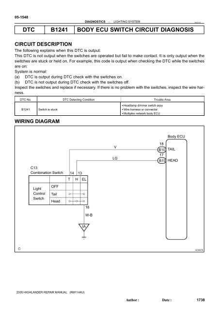
DTC B1241 BODY ECU SWITCH CIRCUIT DIAGNOSIS<br />
05IQ7-01<br />
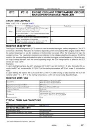
CIRCUIT DESCRIPTION<br />
The following explains when this DTC is output:<br />
This DTC is not output when the <strong>switch</strong>es are operated but fail to make contact. It is only output when the<br />
<strong>switch</strong>es are stuck or held on. For example, this code is output when checking the DTC while the <strong>switch</strong>es<br />
are on:<br />
System is normal:<br />
(a) DTC is output during DTC check with the <strong>switch</strong>es on.<br />
(b) DTC is not output during DTC check with the <strong>switch</strong>es off.<br />
Inspect the <strong>switch</strong>es and replace if necessary. If there is no problem with the <strong>switch</strong>es, inspect the wire harness.<br />
DTC No. DTC Detecting Condition Trouble Area<br />
B1241<br />
Switch is stuck<br />
Headlamp dimmer <strong>switch</strong> assy<br />
Wire harness or connector<br />
Multiplex network <strong>body</strong> ECU<br />
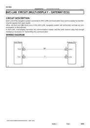
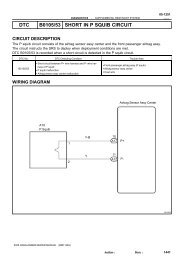
WIRING DIAGRAM<br />
V<br />
LG<br />
18<br />
B10<br />
17<br />
B10<br />
Body ECU<br />
TAIL<br />
HEAD<br />
C13<br />
Combination Switch<br />
14 13<br />
T H EL<br />
Light<br />
Control<br />
Switch<br />
OFF<br />
Tail<br />
Head<br />
16<br />
W-B<br />
IA<br />
E74075<br />
2005 HIGHLANDER REPAIR MANUAL (RM1144U)<br />
Author:<br />
Date:<br />
1738
DIAGNOSTICS - LIGHTING SYSTEM<br />
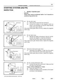
INSPECTION PROCEDURE<br />
1 READ VALUE OF HAND-HELD TESTER<br />
05-1549<br />
(a) Connect the hand-held tester to the DLC3.<br />
(b) Turn the ignition <strong>switch</strong> to the ON position and turn the hand-held tester main <strong>switch</strong> on.<br />
(c) Select the item below in the DATA LIST and read the display on hand-held tester.<br />
BODY NO.1 (MULTIPLEX NETWORK BODY ECU):<br />
Item<br />
HEAD LIGHT SW<br />
TAIL LIGHT SW<br />
OK<br />
Measurement Item/<br />
Display (Range)<br />
Headlight control<br />
SW signal/ ON or OFF<br />
Tail light SW signal/<br />
ON or OFF<br />
Normal Condition<br />
ON: Light control <strong>switch</strong> is in HEAD position<br />
OFF: Light control <strong>switch</strong> is in except HEAD position<br />
ON: Light control <strong>switch</strong> is in TAIL position<br />
OFF: Light control <strong>switch</strong> is in except TAIL position<br />
OK: Condition sign can be displayed.<br />
NG Go to step 2<br />
REPLACE MULTIPLEX NETWORK BODY ECU<br />
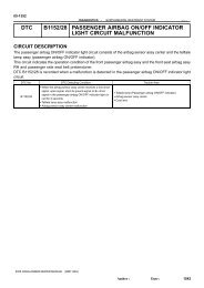
2 INSPECT HEADLAMP DIMMER SWITCH ASSY<br />
Diagnostic Note<br />
-<br />
-<br />
Connector Front View:<br />
C13<br />
(a)<br />
Inspect light control <strong>switch</strong>.<br />
(1) Measure the resistance according to the value(s) in<br />
the table below.<br />
Standard:<br />
Tester connection Condition Specified condition<br />
14 - 16 TAIL Below 1 Ω<br />
13 - 16<br />
14 - 16<br />
HEAD<br />
Below 1 Ω<br />
E11948<br />
NG<br />
REPLACE HEADLAMP DIMMER SWITCH ASSY<br />
(SEE PAGE 65-25 )<br />
OK<br />
2005 HIGHLANDER REPAIR MANUAL (RM1144U)<br />
Author:<br />
Date:<br />
1739
05-1550<br />
DIAGNOSTICS<br />
-<br />
LIGHTING SYSTEM<br />
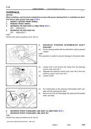
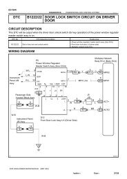
3 CHECK HARNESS AND CONNECTOR(HEADLAMP DIMMER SWITCH ASSY -<br />
MULTIPLEX NETWORK BODY ECU)<br />
Headlamp Dimmer Switch Connector<br />
Front View: C13<br />
E11948<br />
(a)<br />
(b)<br />
Disconnect the headlamp dimmer <strong>switch</strong> assy connector<br />
and B10 connector from the multiplex network <strong>body</strong> ECU.<br />
Measure the resistance according to the value(s) in the<br />
table below.<br />
Standard:<br />
Tester connection Condition Specified condition<br />
C13-13 - B10-17 Always Below 1 Ω<br />
C13-14 - B10-18 Always Below 1 Ω<br />
B10-17 - Body ground Always 10 kΩ or higher<br />
B10-18 - Body ground Always 10 kΩ or higher<br />
C13-16 - Body ground Always Below 1 Ω<br />
Multiplex Network Body ECU<br />
Connector Front View:<br />
B10<br />
B10-18<br />
B10-17<br />
E74263<br />
NG REPAIR OR REPLACE HARNESS OR<br />
CONNECTOR<br />
OK<br />
REPLACE MULTIPLEX NETWORK BODY ECU<br />
2005 HIGHLANDER REPAIR MANUAL (RM1144U)<br />
Author:<br />
Date:<br />
1740