
Create successful ePaper yourself
Turn your PDF publications into a flip-book with our unique Google optimized e-Paper software.
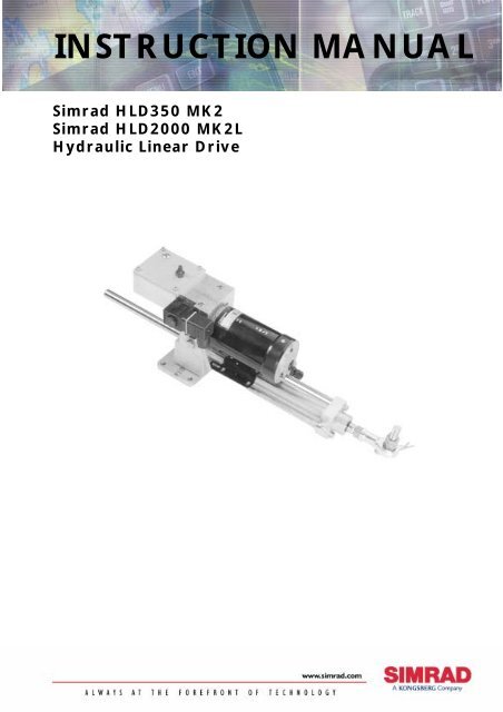
INSTRUCTION MANUAL<br />
<strong>Simrad</strong> <strong>HLD350</strong> MK2<br />
<strong>Simrad</strong> HLD2000 MK2L<br />
Hydraulic Linear Drive
Note!<br />
<strong>Simrad</strong> AS makes every effort to ensure that the information contained within this<br />
document is correct. However, our equipment is continuously being improved and<br />
updated, so we cannot assume liability for any errors which may occur.<br />
Warning!<br />
The equipment to which this manual applies must only be used for the purpose for which<br />
it was designed. Improper use or maintenance may cause damage to the equipment or<br />
injury to personnel. The user must be familiar with the contents of the appropriate<br />
manuals before attempting to operate or work on the equipment.<br />
<strong>Simrad</strong> AS disclaims any responsibility for damage or injury caused by improper<br />
installation, use or maintenance of the equipment.<br />
Copyright<br />
© 2003 <strong>Simrad</strong> AS<br />
The information contained within this document remains the sole property of <strong>Simrad</strong> AS.<br />
No part of this document may be copied or reproduced in any form or by any means, and<br />
the information contained within is not to be communicated to a third party, without the<br />
prior written consent of <strong>Simrad</strong> AS.
Instruction manual<br />
Instruction <strong>Manual</strong><br />
This manual is intended as a reference guide for correctly installing<br />
and maintaining the <strong>HLD350</strong> MK2 and HLD2000 MK2 Hydraulic<br />
Linear Drives.<br />
Please take time to read this manual to get a thorough understanding of<br />
the drive system components and its relationship to a complete autopilot<br />
system.<br />
Other documentation material that is provided with your system<br />
includes a warranty card. This must be filled out by the authorized<br />
dealer that performed the installation and mailed in to activate the<br />
warranty.<br />
Instruksjonsmanual<br />
Denne manualen gir veiledning om installasjon og vedlikehold av de<br />
hydrauliske drivenhetene <strong>HLD350</strong> MK2 og HLD2000 MK2.<br />
For å få en forståelse av drivenhetens virkemåte og funksjon i et<br />
autopilotsystem bør manualen leses grundig.<br />
Sammen med ditt system følger et garantikort. Dette må fylles ut av<br />
installatør og sendes inn for at garantien skal være gyldig.<br />
20220109D 1
<strong>Simrad</strong> Hydraulic Linear Drive<br />
Document revisions<br />
Documentation<br />
department<br />
Hardware/Software<br />
design<br />
Project/Product<br />
Management<br />
Rev Date Sign Date Sign Date Sign<br />
– 07.97 N.G. 07.97 I.K. 07.97 Th.H.<br />
A 29.04.98 N.G. 29.04.98 I.K. 29.04.98 Th.H.<br />
B 21.09.99 N.G. 21.09.99 I.K. 21.09.99 Th.H.<br />
C 15.11.00 N.G. 16.11.00 I.K. 16.11.00 Th.H.<br />
D 19.02.03 N.G. 19.02.03 I.K. 19.02.03 Th.H.<br />
Document history<br />
Rev. – First edition<br />
Rev. A New edition including MK2 versions<br />
Rev. B Added measurement on figure 1. Adjusted figure 5.<br />
Rev. C New environmentally friendly synthetic hydraulic oil, page 5, 6 and 7.<br />
Corrected quantity for Pos.8 Bearing bush on fig. 11 from 1 to 2 and<br />
description of P.N. 44165918 on page 23. Distributor list updated.<br />
Rev. D New motors, type Lemac. Added colour on the o-ring at pos. 6, page 21<br />
to avoid mix up. Minor corrections in text.<br />
2 20220109D
Instruction manual<br />
Contents<br />
1 GENERAL..............................................................................................................5<br />
2 TECHNICAL SPECIFICATIONS.......................................................................7<br />
2.1 Standard version .............................................................................................7<br />
2.2 Split version....................................................................................................8<br />
2.3 Dual cylinder version......................................................................................9<br />
2.4 Comparison chart for HLD MK2 versions ...................................................10<br />
3 INSTALLATION .................................................................................................11<br />
3.1 Mechanical installation.................................................................................11<br />
3.2 Electrical connection ....................................................................................12<br />
J300X/J3000X Junction Unit........................................................................12<br />
J101A Junction Unit .....................................................................................12<br />
4 CONSTRUCTION AND PRINCIPLE OF OPERATION...............................15<br />
4.1 Tank ..............................................................................................................15<br />
4.2 Reversible Hydraulic Pump..........................................................................16<br />
4.3 Hydraulic Rudder Cylinder ..........................................................................16<br />
5 PARTS LIST.........................................................................................................19<br />
5.1 Linear drive units and main parts .................................................................19<br />
5.2 Tank assembly ..............................................................................................20<br />
5.3 Pump assembly .............................................................................................21<br />
5.4 Cylinder assembly ........................................................................................22<br />
6 APPENDIX ...........................................................................................................24<br />
6.1 Calculation of the force against the rudder...................................................24<br />
20220109D 3
<strong>Simrad</strong> Hydraulic Linear Drive<br />
Innhold<br />
1 GENERELT............................................................................................................6<br />
2 TEKNISKE SPESIFIKASJONER.......................................................................7<br />
2.1 Delt versjon.....................................................................................................8<br />
2.2 Dobbel sylinder versjon..................................................................................9<br />
2.3 Sammenligningstabell for MK2 versjoner ...................................................10<br />
3 INSTALLASJON .................................................................................................13<br />
3.1 Mekanisk installasjon ...................................................................................13<br />
3.2 Elektrisk tilkobling .......................................................................................14<br />
J300X/J3000X koblingsenhet.......................................................................14<br />
J101A koblingsenhet ....................................................................................14<br />
4 KONSTRUKSJON OG VIRKEMÅTE .............................................................17<br />
4.1 Tank ..............................................................................................................17<br />
4.2 Reverserbar hydraulisk pumpe .....................................................................17<br />
4.3 Hydraulisk rorsylinder..................................................................................18<br />
5 PARTS LIST.........................................................................................................19<br />
5.1 Linear drive units and main parts .................................................................19<br />
5.2 Tank assembly ..............................................................................................20<br />
5.3 Pump assembly .............................................................................................21<br />
5.4 Cylinder assembly ........................................................................................22<br />
6 TILLEGG .............................................................................................................26<br />
4 20220109D
Instruction manual<br />
1 GENERAL<br />
<strong>HLD350</strong> MK2 and HLD2000 MK2 are hydraulic linear drives<br />
designed for boats with mechanical steering systems such as wire and<br />
cable steering (Edson, Whitlock, Teleflex).<br />
The HLD is a compact, assembled unit, consisting of a reversible<br />
hydraulic pump, a balanced hydraulic cylinder, by-pass valve and oil<br />
tank.<br />
Because of the direct connection to the rudder, the hydraulic linear<br />
drive can be used even if the hand steering should fail. This can be an<br />
important safety factor.<br />
The by-pass valve makes it possible to use the helm with little back<br />
drive force when the autopilot is switched off.<br />
The <strong>HLD350</strong> MK2 and HLD2000 MK2L supersede the previous<br />
<strong>HLD350</strong> and HLD2000L models. This manual also includes<br />
HLD2000 MK2D. This model is based on the same main parts as<br />
<strong>HLD350</strong> MK2, but uses the HLD2000 MK2LD motor.<br />
The MK2 versions were introduced in April 1998. The cylinder has a<br />
slightly increased diameter and requires a modified piston assembly<br />
and piston sealing. Otherwise the MK2 versions are identical to the<br />
previous <strong>HLD350</strong> and HLD2000L. The modified units have got a MK2<br />
added to the type designation on the product label and applies from the<br />
following serial numbers and onwards.<br />
The basic specifications are:<br />
Art. no. Ser. no. Description<br />
21113303 545H36 <strong>HLD350</strong> MK2 (200 mm stroke)<br />
21113311 545H36 <strong>HLD350</strong> MK2S (split version)<br />
21113360 4154H69 HLD2000 MK2L (long version, 340 mm<br />
stroke)<br />
21113386 4154H610 HLD2000 MK2LS (long, split version)<br />
21113345 3383H68 HLD2000 MK2D (dual cylinder version,<br />
200 mm stroke)<br />
21113402 4154H611 HLD2000 MK2LD (long dual cylinder<br />
version)<br />
In this manual HLD is used as a general term for all models. The MK2<br />
designation is added only when specifically required for parts<br />
identifications.<br />
All HLD models are supplied with environmentally friendly synthetic<br />
hydraulic oil with designation of type Hydralen 32 (viscosity 32 cSt).<br />
This oil can without problem substitute/blend with ordinary hydraulic<br />
oil with equivalent viscosity (between 15 and 40 cSt)<br />
20220109D 5
<strong>Simrad</strong> Hydraulic Linear Drive<br />
GENERELT<br />
<strong>HLD350</strong> MK2 og HLD2000 MK2 er hydrauliske lineære drivenheter<br />
beregnet for båter med mekaniske styresystemer som kabel- og<br />
wirestyring (Edson, Whitlock, Teleflex).<br />
Den består av en kompakt sammenbygget enhet som inneholder<br />
reverserbar hydraulisk pumpe, balansert hydraulisk sylinder, by-pass<br />
ventil og oljetank.<br />
På grunn av den direkte tilkoblingen til roret vil den lineære<br />
drivenheten kunne brukes selv om håndstyringen skulle svikte, noe<br />
som gir større sikkerhet.<br />
Når autopiloten er avslått eller mister spenningen, vil by-pass ventilen<br />
åpne slik at roret kan beveges uhindret ved hjelp av den mekaniske<br />
styringen.<br />
<strong>HLD350</strong> MK2 og HLD2000 MK2L etterfølger de tidligere modellene<br />
<strong>HLD350</strong> og HLD2000L. <strong>Manual</strong>en omhandler også HLD2000<br />
MK2D. Denne modellen baserer seg på samme hoveddeler som<br />
<strong>HLD350</strong> MK2, men bruker samme motor som HLD2000 MK2LD.<br />
MK2 versjonen ble introdusert i april 1998. Sylinderen har en noe<br />
større diameter og krever et modifisert stempel og stempelforing.<br />
Ellers er MK2 versjonene identiske med <strong>HLD350</strong> og HLD2000L.<br />
Modifiserte enheter har fått tilføyd MK2 på produktmerkelappen og<br />
modifikasjonen er gjort gjeldende fra følgende serienummer:<br />
Art. nr. Ser. nr. Beskrivelse<br />
21113303 545H36 <strong>HLD350</strong> MK2 (200 mm slaglengde)<br />
21113311 545H36 <strong>HLD350</strong> MK2S (delt utgave)<br />
21113360 4154H69 HLD2000 MK2L (lang utgave, 340 mm<br />
slaglengde)<br />
21113386 4154H610 HLD2000 MK2LS (lang, delt utgave)<br />
21113345 3383H68 HLD2000 MK2D (dobbel sylinder,<br />
200 mm slaglengde)<br />
21113402 4154H611 HLD2000 MK2LD (lang, dobbel sylinder)<br />
I denne manualen brukes HLD som en generell betegnelse for alle<br />
modeller. MK2 er kun brukt når det er behov for å identifisere deler.<br />
Alle HLD modeller leveres med en syntetisk, miljøvennlig<br />
hydraulikkolje av typen Hydralen 32 (Viskositet 32 cSt). Denne oljen<br />
kan uten problem erstatte/blandes med vanlig hydrolikkolje med<br />
tilsvarende viskositet (mellom 15 og 40 cSt).<br />
6 20220109D
Instruction manual<br />
2 TECHNICAL SPECIFICATIONS<br />
2.1 Standard version<br />
Motor voltage:................................12V DC<br />
Max. current <strong>HLD350</strong>/2000L: .......10/20A<br />
Average power consumption: ........40 – 60 W<br />
Peak thrust <strong>HLD350</strong>/2000L: ..........350kp / 500kp<br />
Continuous duty <strong>HLD350</strong>/2000L: .250kp / 390kp<br />
Max. speed <strong>HLD350</strong>/2000L: .........10 sec./17 sec. full travel<br />
(Adjustable in the autopilot<br />
electronics)<br />
Stroke: ............................................200mm / 340mm<br />
Overall length with piston in<br />
middle position:..............................578mm / 858mm<br />
Dimensions:....................................See fig. 1<br />
Hydraulic oil: .............Hydralen 32, High quality environmentally<br />
friendly, synthetic hydraulic oil.<br />
Alternative oil: ...........Norol HM32, Shell Tellus 27, Esso HP15 and<br />
Yukong Supervis AW32/X32.)<br />
Viscosity 15-40 cSt at 40°C.<br />
{350mm (13 ¾”)}<br />
Figure 1 HLD dimensions (shown with Fracmo motor)<br />
20220109D 7
<strong>Simrad</strong> Hydraulic Linear Drive<br />
2.2 Split version<br />
To obtain good flexibility in the installation of the HLD, a split<br />
version is available.<br />
The hydraulic cylinder and the motor/pump-unit are made as separate<br />
units with provisions to connect hydraulic hoses between the two.<br />
Modifications have been made on the pump housing for this purpose.<br />
The split version is available with standard (200 mm) or long stroke<br />
(340 mm) and with hose lengths of 1 m (3 ft).<br />
Figure 2 HLD Split version (Shown with Fracmo type motor)<br />
For å oppnå best mulig fleksibilitet ved installasjon er enheten<br />
tilgjengelig i delt utgave.<br />
Hydraulisk sylinder og motor/pumpeenhet er laget som separate<br />
enheter for sammenkobling ved hjelp av hydraulikk-slanger. I denne<br />
forbindelse er det gjort små modifikasjoner på de to enhetene.<br />
Delt utgave kan leveres både med standard slaglengde (200 mm)og<br />
med lang slaglengde (340 mm), og med slanger på 1,0 m.<br />
8 20220109D
Instruction manual<br />
2.3 Dual cylinder version<br />
This model meets the requirement for increased torque without<br />
increasing the radial forces on the rudder stock.<br />
It combines a powerful reversible pump (RPU300) with two cylinders<br />
having the standard stroke or long stroke. 4 flexible hoses of 1 m (3 ft)<br />
connect the pump to the cylinders.<br />
By connecting the cylinders as shown, the radial forces are balanced<br />
out, whilst a double torque has been achieved.<br />
The dual cylinder version is for 24V DC operation only.<br />
Figure 3 HLD Dual cylinder (Shown with Fracmo type motor)<br />
Denne utgaven med doble sylindere er utviklet for å øke dreiemomentet<br />
uten å øke de radielle kreftene som virker på rorstammen.<br />
Den kombinerer en kraftigere reverserbar pumpe (RPU300), med to<br />
sylindere med standard slaglengde, eventuelt med lang slaglengde. 4<br />
oljeslanger på 1 m forbinder pumpen med sylindrene. Ved å montere<br />
sylindrene som vist på figuren får man balansert de radielle kreftene,<br />
samtidig som dobbelt dreiemoment oppnås.<br />
Den doble sylinderversjonen er kun beregnet for 24V DC.<br />
20220109D 9
<strong>Simrad</strong> Hydraulic Linear Drive<br />
2.4 Comparison chart for HLD MK2 versions<br />
MODEL<br />
MOTOR<br />
VOLTS<br />
JUNC-<br />
TION<br />
UNIT<br />
MAX<br />
STROKE<br />
mm (in.)<br />
PEAK<br />
THRUST<br />
kg (lb.)<br />
MAX<br />
RUDDER<br />
TORQUE<br />
Nm<br />
(lb.in.)<br />
HARD-<br />
OVER<br />
TIME<br />
sec.<br />
(30% load)<br />
PWR.<br />
CON-<br />
SUMP.<br />
TILLER<br />
ARM<br />
mm<br />
(in.)<br />
<strong>HLD350</strong><br />
<strong>HLD350</strong>S<br />
12V J3000X 200 (7,9) 350<br />
(770)<br />
610<br />
(5400)<br />
12 3,5-10 A 175<br />
(6,9)<br />
HLD2000L<br />
HLD2000LS<br />
12V J300X 340 (13,4) 500<br />
(1100)<br />
1460 (12850) 12 5-16 A 298<br />
(11,7)<br />
HLD2000D 24V J300X 200 (7,9) 1050<br />
(2310)<br />
HLD2000LD 24V J300X 340 (13,4) 1050<br />
(2310)<br />
1800<br />
(15900)<br />
3180<br />
(28000)<br />
9 5-16 A 175<br />
(6,9)<br />
15 5-16 A 298<br />
(11,7)<br />
Steering gear interface: Connects to quadrant or tiller.<br />
1. The junction unit steps down the motor voltage when operating<br />
from 24V or 32V mains.<br />
2. The specified junction unit is necessary to achieve max drive unit<br />
capacity.<br />
3. Recommended operational thrust or torque is 70% of listed value.<br />
4. Typical average power consumption is 40% of listed maximum<br />
value.<br />
Rortilkobling: Kobles til kvadrant eller rorkult.<br />
1. Koblingsenheten regulerer ned motorspenningen ved 24V eller<br />
32V nettspenning.<br />
2. Spesifisert koblingsenhet er nødvendig for å oppnå maksimal<br />
kapasitet fra drivenhet.<br />
3. Anbefalt skyvkraft eller moment ved drift er 70% av oppgitt verdi.<br />
4. Gjennomsnittlig effektforbruk er typisk 40% av oppgitt<br />
maksimumsverdi.<br />
10 20220109D
Instruction manual<br />
3 INSTALLATION<br />
Refer to table in section 2.4 to verify that appropriate HLD model is<br />
selected for your boat.<br />
If there is any doubt as to whether <strong>HLD350</strong>/HLD2000L can be<br />
installed, this can be clarified by undertaking the calculations shown<br />
in the appendix.<br />
3.1 Mechanical installation<br />
Note !<br />
Caution !<br />
cm<br />
24<br />
DISTANCE R AND S<br />
AVSTAND R OG S<br />
Rudder and actuator rod is set to midposition. To obtain maximum<br />
and smooth thrust over the actuator's complete stroke, the HLD should<br />
be installed in accordance with fig. 6. The distances R and S for<br />
different rudder angles are found in the diagram in fig. 4 and 5.<br />
The HLD should be fitted with the enclosed safety connector between<br />
actuator and tiller to ensure quick disconnection in emergency<br />
situations.<br />
Drill and tap the rudder tiller (M12x1.75) to secure the bolt firmly.<br />
Do never install the unit upside down! (The air valve should be<br />
facing upwards.) The HLD must be installed horizontally only. No<br />
more than ±5 degrees tilt is allowed at any position, as illustrated on<br />
figure 1. The HLD should not act as an end stop for the rudder.<br />
cm<br />
40<br />
DISTANCE R AND S<br />
AVSTAND R OG S<br />
22<br />
36<br />
20<br />
18<br />
R<br />
32<br />
28<br />
R<br />
16<br />
14<br />
S<br />
24<br />
20<br />
S<br />
12<br />
16<br />
10<br />
12<br />
8<br />
8<br />
25 30 35 40 45<br />
RUDDER ANGLE / RORVINKEL<br />
50 55 60<br />
DEGREES<br />
GRADER<br />
25 30 35 40 45<br />
RUDDER ANGLE / RORVINKEL<br />
50 55 60<br />
DEGREES<br />
GRADER<br />
Figure 4 <strong>HLD350</strong> Installation diagram<br />
Figure 5 HLD2000L Installation diagram<br />
20220109D 11
<strong>Simrad</strong> Hydraulic Linear Drive<br />
Remove the valve cap on the tank when the unit is installed.<br />
Figure 6 HLD Installation<br />
3.2 Electrical connection<br />
J300X/J3000X Junction Unit<br />
The HLD is connected to the autopilot via J300X or J3000X Junction<br />
unit according to the following diagram:<br />
HYDRAULIC<br />
LINEAR DRIVE<br />
JUNCTION UNIT<br />
POWER PCB<br />
TB1 TB2 TB3 TB4 TB5<br />
TB6<br />
TB7<br />
Sol. -Motor<br />
Sol. -Motor<br />
Bypass<br />
Clutch<br />
Single pole<br />
clutch/bypass<br />
switch<br />
Figure 7 HLD connection to J3XX Junction Unit<br />
J101A Junction Unit<br />
The HLD can also be connected to previous models autopilots using<br />
the J45A, J101A or J1000 Junction units. The Junction Unit controls<br />
the current to the motor and the bypass valve. The Junction Unit also<br />
has built-in speed regulation of the HLD, which allows rudder speed<br />
12 20220109D
Instruction manual<br />
adjustment (i.e. the steering performance of the boat when autopilot<br />
steering) after installation of the system.<br />
Note that for the <strong>HLD350</strong> (not the HLD2000L) the trim potentiometer<br />
RV1 in J1000/J101A/J45A should be adjusted to approx. 2/3 of full<br />
C.W. position.<br />
The J1000/J101A/J45A also has a built-in current limiter to prevent<br />
overload of the motor (Max. current is 20A).<br />
Motor/bypass connection<br />
The bypass valve is connected to terminal 13 and 14 in<br />
J45A/J101A/J1000, and is polarity independent.<br />
The motor is connected to terminal A and B in J45A/J101A/J1000.<br />
Interchange of A and B will change the direction of rotation.<br />
Cable for the motor supply voltage from the ship mains must be at<br />
least 2x4mm 2 (AWG10), and fused according to the table enclosed<br />
with the J101A/J1000.<br />
INSTALLASJON<br />
Kontroller mot tabellen under seksjon 2.4 at riktig HLD model er<br />
valgt.<br />
Er det tvil om hvorvidt <strong>HLD350</strong> eller HLD2000L skal velges, kan<br />
dette klargjøres ut fra beregningene som er vist i tillegget bak i<br />
manualen.<br />
Mekanisk installasjon<br />
Plasser stempelstang og ror i midtstilling. HLD monteres slik fig. 6<br />
viser for å få maksimal skyvkraft langs hele stempelstangens<br />
vandring. Avstandene R og S ved de forskjellige rorvinkler finnes i<br />
diagram fig. 4 og 5.<br />
HLD er utstyrt med hurtigkopling mellom stempelstang og rorkult<br />
som tillater hurtig frakobling i nødssituasjoner.<br />
Bruk M12x1,75 gjengetapp og gjeng opp i rorkult.<br />
HLD må aldri monteres opp ned! (Lufteventil på tank skal peke<br />
oppover). Enheten må monteres horisontalt, og slik at avviket fra<br />
horisontalplanet aldri overstiger ±5 grader, slik som illustrert på<br />
fig. 1. HLD må ikke monteres slik at den fungerer som endestopp<br />
for roret.<br />
Husk å skru av ventilhetten på tanken etter at enheten er montert.<br />
20220109D 13
<strong>Simrad</strong> Hydraulic Linear Drive<br />
Elektrisk tilkobling<br />
J300X/J3000X koblingsenhet<br />
HLD kobles til autopiloten via J300X eller J3000X koblingsenhet i<br />
henhold til fig. 7.<br />
J101A koblingsenhet<br />
HLD kan også kobles til tidligere autopilotmodeller som bruker<br />
J101A eller J1000 koblingsenheter. Koblingsenhetene kontrollerer<br />
strømmen til motoren og by-pass ventilen. Koblingsenheten har også<br />
innebygget hastighetsregulering av HLD, noe som gir anledning til å<br />
justere rorhastighet (og dermed båtens styreegenskaper med autopilot)<br />
etter at systemet er installert.<br />
Ved bruk av <strong>HLD350</strong> (gjelder ikke HLD2000L) bør trimmepotensiometer<br />
RV1 i J45A/J101A/J1000settes til ca. 2/3 av fullt<br />
område.<br />
I J45A/J101A/J1000er det også innebygget en strømbegrenser som<br />
hindrer overbelastning av motor (maks. strøm er 20A).<br />
Kobling av motor/bypassventil:<br />
Bypassventil kobles til terminal 13 og 14 i J45A/J101A/J1000og er<br />
polaritetsuavhengig.<br />
Motoren kobles til terminal A og B i J45A/J101A/J1000. Ombytting<br />
av A og B vil snu motorens dreieretning.<br />
Kabel for motorspenning fra båtens fordelingsskap må være minst<br />
2x4mm 2 og sikret i.h.h.t. tabell vedlagt i J45A/J101A/J1000.<br />
14 20220109D
Instruction manual<br />
4 CONSTRUCTION AND PRINCIPLE OF<br />
OPERATION<br />
4.1 Tank<br />
The HLD is delivered completely assembled with tank, reversible<br />
hydraulic pump and a balanced hydraulic cylinder. The HLD is<br />
therefore a completely closed system.<br />
The tank is machined out of<br />
solid aluminium and all<br />
necessary oil ways are<br />
drilled out.<br />
A bypass valve is mounted<br />
in the tank, to allow the<br />
mechanical steering system<br />
to be used, when the<br />
autopilot is not in operation.<br />
The bypass valve is a<br />
standard ON/OFF solenoid<br />
valve, normally open.<br />
When the autopilot is in<br />
STBY mode, the solenoid<br />
valve will be in open<br />
position.<br />
When AUTO or NAV mode<br />
is selected, the solenoid<br />
valve will be in closed<br />
position.<br />
The solenoid valve opens<br />
immediately when the<br />
autopilot is switched off,<br />
and handsteering is<br />
allowed.<br />
Previous versions<br />
An early version of<br />
Functional diagram<br />
1. Electrical motor (Elektromotor)<br />
2. Gear pump (Tannhjulspumpe)<br />
3. Suction valve (Innsugingsventil)<br />
4. Check valve (Tilbakeslagsventil)<br />
5. Oil tank (Oljetank)<br />
6. By-pass valve (By-pass ventil)<br />
7. Hydraulic actuator (Hydraulisk<br />
sylinder)<br />
<strong>HLD350</strong> and <strong>HLD350</strong>S did not have check valves. The following serial<br />
no. codes can identify it: H30 (<strong>HLD350</strong>) and H31 (<strong>HLD350</strong>S).<br />
The principle of operation was similar to that of HLD2000L. The<br />
(suction) valves, however, operated as combined suction and (nonreturn)<br />
check valves controlled by internal pressure and direction of oil<br />
flow. The resulting effect was a smoother check valve operation as<br />
7<br />
4 5<br />
4<br />
M<br />
6<br />
3 3<br />
2<br />
1<br />
20220109D 15
<strong>Simrad</strong> Hydraulic Linear Drive<br />
compared to the ones with separate check valves. It should be observed<br />
however, that this version does not have the extra protection against<br />
internal leakage (bypass) as the models with separate check valves.<br />
4.2 Reversible Hydraulic Pump<br />
The pump consists of valve block, reversible gear pump, pressure<br />
operated check (non-return) valves, electric permanent magnet motor,<br />
suction valves and slide.<br />
The pump is reversible, i.e. the motor changes direction of rotation<br />
and the gear pump delivers oil to that side of the rudder cylinder<br />
dictated by the signal from the autopilot. When the motor is running,<br />
the pressurised (or delivery) side will hold both check valves open,<br />
using direct oil pressure upon the valve on the delivery side. This oil<br />
pressure is also used to push a slide to open the valve on the suction<br />
side.<br />
When the motor stops, the spring in the check valve on the suction<br />
side returns the slide to the neutral position. Both check valves are<br />
now closed and the rudder cylinder locked. Both sides of the gear<br />
pump are able to suck oil from the tank through the suction valves.<br />
4.3 Hydraulic Rudder Cylinder<br />
The rudder cylinder consists of the cylinder itself, actuator, actuator<br />
rod, ball joint and base plate.<br />
The actuator rod runs through the cylinder. The actuator area is<br />
identical on both sides, and this balances the cylinder.<br />
Figure 8 HLD Assembly drawing (N3-111832)<br />
(Shown with Fracmo type motor)<br />
16 20220109D
Instruction manual<br />
KONSTRUKSJON OG VIRKEMÅTE<br />
HLD leveres komplett sammenbygget med tank, reverserbar<br />
hydraulisk pumpe og balansert hydraulisk sylinder. Den arbeider<br />
dermed i et lukket system.<br />
Tank<br />
Tanken er frest ut av massiv aluminium og nødvendige oljeløp er<br />
utboret.<br />
I tanken er det montert en bypass-ventil for at det mekaniske<br />
styresystemet skal kunne brukes når autopiloten ikke er i bruk.<br />
Bypass-ventilen er en standard Av/På magnetventil som normalt er<br />
åpen.<br />
Magnetventilen er åpen når autopiloten er i STBY og lukket når<br />
autopiloten er i AUTO eller NAV. Ventilen åpner umiddelbart når<br />
autopiloten slås av slik at håndstyring kan benyttes.<br />
Tidligere versjoner<br />
En tidligere versjon av <strong>HLD350</strong> og <strong>HLD350</strong>S har ikke<br />
tilbakeslagsventil. Denne versjonen identifiseres med følgende serie<br />
nr. kode: H30 (<strong>HLD350</strong>) og H31 (<strong>HLD350</strong>S).<br />
Betjeningsprinsippet var tilsvarende som for HLD2000L.<br />
Innsugnings-ventilene fungerte imidlertid som kombinerte innsugingsog<br />
tilbakeslagsventiler kontrollert av det interne trykket og retningen<br />
av oljestrømmen. Effekten av dette var en jevnere sperrefunksjon<br />
sammenlignet med enheter med egen tilbakeslagsventil. Denne<br />
versjonen gir imidlertid ikke den ekstra beskyttelse mot intern<br />
lekkasje som den med egen tilbakeslagsventil gir.<br />
Reverserbar hydraulisk pumpe<br />
Pumpen består av ventilblokk, pumpeenhet, motor med permanente<br />
magneter, tilbakeslagsventiler og sleide.<br />
Pumpen er reverserbar, dvs. at motoren kan endre dreieretning og<br />
tannhjulspumpen vil levere oljen enten til den ene eller andre enden av<br />
rorsylinderen, avhengig av signalene fra autopiloten.<br />
Når motoren går, vil pumpens trykkside holde begge de trykkstyrte<br />
tilbakeslagsventilene åpne. Tilbakeslagsventilen på trykksiden åpnes<br />
direkte av oljetrykket, mens den på sugesiden blir åpnet av en sleide<br />
som skyves over av oljetrykket på trykksiden.<br />
Når signalet fra piloten opphører, vil fjæren i tilbakeslagsventilen på<br />
sugesiden trykke sleiden tilbake til nøytralstilling. Begge<br />
tilbakeslagsventilene vil da være lukket. Den hydrauliske sylinderen<br />
20220109D 17
<strong>Simrad</strong> Hydraulic Linear Drive<br />
er dermed låst. Begge sider av tannhjulspumpen kan suge fra tank via<br />
innsugningsventiler.<br />
Hydraulisk rorsylinder<br />
Rorsylinderen består av sylinderrør, stempelstang med stempel,<br />
endestykke og fot.<br />
Stempelstangen er gjennomgående. Stempelarealet er likt på begge<br />
sider, og sylinderen er dermed balansert.<br />
18 20220109D
Instruction manual<br />
5 PARTS LIST<br />
5.1 Linear drive units and main parts<br />
Refer to Figure 8.<br />
Pos. Part no. Description<br />
21113303 <strong>HLD350</strong> MK2 Hydraulic linear drive complete, stroke<br />
200 mm<br />
21113311 <strong>HLD350</strong> MK2S Hydraulic linear drive complete, stroke<br />
200 mm, split version<br />
21113360 HLD2000 MK2L Hydraulic linear drive complete, stroke<br />
340 mm<br />
21113386 HLD2000 MK2LS Hydraulic linear drive complete,<br />
stroke 340 mm, split version<br />
21113345 HLD2000 MK2D Hydraulic linear drive complete, stroke<br />
200 mm, dual cylinders<br />
21113402 HLD2000 MK2LD Hydraulic linear drive complete,<br />
stroke 340 mm, dual cylinders<br />
1 21112826 Tank assembly 12V (standard)<br />
Option: 24V (voltage to be specified)<br />
2 21112859 Pump assembly complete with motor (12V)<br />
Motor parts (LEMAC)<br />
44140713 RPU80 Lemac motor (<strong>HLD350</strong>/S)<br />
(Substitutes RPU80 Fracmo motor)<br />
44177525 RPU160 Lemac motor (HLD2000L/LS)<br />
(Substitutes RPU100 Fracmo motor)<br />
44169845 Brush for RPU80/160 Lemac motor, C8386 9x6x18,2mm<br />
44170132 Brush cap for RPU80/160 Lemac motor<br />
44169993 RPU300 Lemac motor, 24V (HLD2000D/LD)<br />
(Substitutes RPU300 Fracmo motor, 24V)<br />
44170116 Brush for RPU300 Lemac motor, short type,<br />
12,7x7,94x12mm<br />
44170108 Brush for RPU300 Lemac motor, long type,<br />
12,7x7,94x19mm<br />
44170124 Brush cap for RPU300 Lemac motor<br />
Parts for Fracmo motors:<br />
44163228 Brush cap RPU80/160 Fracmo – Type I<br />
20220109D 19
<strong>Simrad</strong> Hydraulic Linear Drive<br />
44163236 Brush cap RPU80/160 Fracmo – Type II<br />
44161933 Brushes for RPU80 motor<br />
44133056 Brushes type CB156 for RPU100 Fracmo (spade<br />
44136356 Brushes type CB174 for RPU100 Fracmo (male/female<br />
connector)<br />
3 21113287 <strong>HLD350</strong>/2000 MK2 (D) Hydraulic cylinder ass’y<br />
21113279 HLD2000 MK2L Hydraulic cylinder ass’y<br />
4 21109228 Emergency release pin complete<br />
5.2 Tank assembly<br />
Figure 9 HLD Tank assembly (N3-111282C)<br />
Pos. Qty Part no. Description<br />
1 1 21112891 Tank<br />
2 1 21112800 Cover for tank<br />
3 1 44156537 Solenoid valve 12V, complete<br />
44157634 Coil 12V<br />
44156594 Solenoid valve 24V, complete<br />
44157626 Coil 24V<br />
4 4 44150555 Screw sock. Head M4x16<br />
20 20220109D
Instruction manual<br />
5 4 44150274 Washer M4<br />
6 1 21112834 Cable<br />
7 1 44154672 O-ring Ø85,34x1,78<br />
8 5 44154839 O-ring 8,73x12,29x1,78<br />
9 1 44153773 Valve with cap<br />
10 1 44154128 Nipple Ø6 R 1/4<br />
11 3 44154565 Set screw M8x8<br />
12 2 44154458 Screw sock. head M6x40<br />
13 1 44157790 O-ring Ø10,82x1,78<br />
14 1 44157774 Blind plug PG7<br />
15 1 44157865 O-ring Ø14,00x2,00<br />
16 1 44157873 O-ring Ø16,36x2,21<br />
5.3 Pump assembly<br />
Figure 10 Pump assembly<br />
Pos. Qty. Part no. Description<br />
1 4 44149912 Screw sock. Head M5x60<br />
2 4 44152775 Screw sock. Head M6x35<br />
3 1 21101191 Pump cover<br />
4 4 44150050 Split washer M6<br />
5 2 44149912 Screw sock. Head M5x60<br />
6 1 44154656 O-ring Ø9,25x1,78 silicon, red<br />
7 1 21109038 Valve block<br />
20220109D 21
<strong>Simrad</strong> Hydraulic Linear Drive<br />
8 2 44118552 Steel ball Ø6,35<br />
10 2 21112933 Grub. screw sock. head M8<br />
11 2 21100276 Valve housing<br />
12 2 44149706 Copper Washer Ø20/24x1,5<br />
13 2 44149649 O-ring 9,25x1,78 Nitrile<br />
14 1 21100268 Slide<br />
15 2 21100292 Plug<br />
16 2 44148146 Copper washer Ø10,2x14x1<br />
17 2 21100193 Spring<br />
18 2 44149656 Steel ball Ø8<br />
19 1 44149722 Oil seal 8x22x7<br />
20 1 21100185 Support ring<br />
21 2 44154888 O-ring Ø18,77x1,78<br />
5.4 Cylinder assembly<br />
Figure 11 Cylinder assembly (N3-111284A)<br />
Pos. Qty. Part no. Description<br />
1 1 21215991 Base plate complete<br />
2 1 21219019 Plastic bearing<br />
22 20220109D
Instruction manual<br />
3 1 21112768 Back end piece<br />
4 2 21219027 Gasket<br />
5 1 21112867 <strong>HLD350</strong> Piston complete<br />
5 1 21113063 <strong>HLD350</strong> MK2 Piston complete<br />
5L 1 21113253 HLD2000L Piston complete<br />
5L 1 21113071 HLD2000 MK2L Piston complete<br />
6 1 21112974 Cylinder<br />
6L 1 21112982 Cylinder<br />
7 4 21109111 Studs<br />
7L 4 21112024 Studs<br />
8 2 21112917 Bearing bush<br />
9 2 44156578 Oil seal 16x24x5,5<br />
10 2 44156586 Cleaner Ø16x24x7,4<br />
11 1 44140076 Nut M12<br />
12 1 21113295 Ball joint Ø12xM12<br />
13 2 44150035 Set screw M6x6<br />
14 2 44150043 Nut M6<br />
15 1 21112784 End piece<br />
16 4 44150050 Washer M6<br />
17 4 44150068 Nut M6<br />
18 2 44148039 Copper washer 12x16x1,5<br />
19 1 44165892 Hollow screw M12x1,5 single<br />
20 1 44165900 Clamping ring coupling M10x1x8<br />
21 1 21113030 Pipe with banjo coupling<br />
21L 1 21113055 Pipe with banjo coupling<br />
22 2 44154565 Set screw M8x8<br />
23 2 44165918 Nut ring UM 35-25-5<br />
24 1 21113048 Bearing bush<br />
20220109D 23
<strong>Simrad</strong> Hydraulic Linear Drive<br />
6 APPENDIX<br />
6.1 Calculation of the force against the rudder<br />
1. When the rudder torque is known.<br />
The rudder torque is usually obtained from the boat builder.<br />
To find the force against the rudder, the length of the rudder tiller<br />
must first be known. This can be calculated from the formula:<br />
l<br />
R = (m)<br />
sin a<br />
where R = rudder tiller length<br />
a = one half of the rudder angle<br />
l = one half of the stroke length(0.10m/0.17m)<br />
The force F against the rudder is calculated from the formula:<br />
F r = M R (kp)<br />
where<br />
F r = rudder force<br />
M = rudder torque (kpm)<br />
R = rudder tiller (m)<br />
Use the table on page 10 to find the appropriate drive unit. If the boat<br />
is going on cruises for several days, it is recommended to select a unit<br />
where Fr not exceeds 70% of listed max. thrust.<br />
2. When the rudder torque is unknown.<br />
First the helm torque must be found. The following<br />
measurements/calculations must be carried out:<br />
At full speed ahead and the rudder hard over, find the maximum force<br />
F required to turn the helm by using a spring balance.<br />
Measure the radius r of the helm. The helm torque is calculated from<br />
the formula:<br />
F<br />
M r = F x r (kpm)<br />
M r = helm torque<br />
F = helm force (kp)<br />
r = helm radius (m)<br />
To convert the helm torque to rudder torque<br />
the turn-over ratio must first be found:<br />
r<br />
24 20220109D
Instruction manual<br />
I =<br />
360T<br />
2a<br />
i = turn-over ratio<br />
T = numbers of turn (hard over-hard over)<br />
a = one half of the rudder angle<br />
Now we can find the rudder torque from the formula:<br />
M = M r x i (kpm)<br />
M = rudder torque<br />
M r = helm torque (kpm)<br />
i = turn-over ratio<br />
When the rudder torque is known, use the same procedure as for point<br />
1 to find the rudder force F.<br />
Example:<br />
The helm force is measured to 6.5kp and the radius to 0.3m. Number<br />
of turns from hard over to hard over is 3 and the total rudder angle is<br />
90 degrees.<br />
Put into the formula: M r = 6.5kp x 0.30m = 1.95kpm<br />
Turn-over ratio: i =<br />
360x3<br />
2x45<br />
= 12<br />
Rudder torque: M = 1.95kpm x 12 = 23.4kpm<br />
Length of rudder tiller R =<br />
0,10<br />
sin 45<br />
= 0.14m<br />
(HLD2000L: R =<br />
0,17<br />
sin 45<br />
= 0.24m)<br />
The length of rudder tiller should be reduced to 0.135m (0.23m), to<br />
avoid the HLD acting as an endstop for the rudder.<br />
Rudder force F r =<br />
23,4kpm<br />
0,135m<br />
= 173kp<br />
(HLD2000L: F r =<br />
23,4kpm<br />
0,23m<br />
= 102kp)<br />
As 173kp (102kp) is less than 350kp the <strong>HLD350</strong> MK2 can be<br />
installed.<br />
20220109D 25
<strong>Simrad</strong> Hydraulic Linear Drive<br />
TILLEGG<br />
Beregning av kraften som virker på roret<br />
1. Når rormomentet er kjent<br />
Rormomentet kan i de fleste tilfeller opplyses av båtprodusenten.<br />
For å finne kraften på roret i kp, må vi først vite hvor lang rorkulten<br />
er. Denne finnes ved hjelp av formelen:<br />
R =<br />
l<br />
sin a<br />
(m)<br />
der R = rorkult<br />
a = halve rorvinkelen<br />
l = halve slaglengden (0.10m/0.17m)<br />
Kraften F r på roret finnes nå ved hjelp av formelen:<br />
F r = M R (kp)<br />
der<br />
F r = kraften som virker på roret<br />
M = rormoment (kpm)<br />
R = rorkult (m)<br />
Bruk tabellen på side 10 for å finne den aktuelle drivenheten. Det<br />
anbefales at Fr ikke overstiger 70% av den oppgitte skyvkraft dersom<br />
båten skal seile kontinuerlig i flere døgn.<br />
2. Når rormomentet er ukjent<br />
Først må vi finne rattmomentet. Følgende målinger/beregninger<br />
utføres:<br />
Fest en fjærvekt til rattet og mål den maksimale kraften F som skal til<br />
for å dreie rattet når båten går med full fart og med roret nesten i<br />
borde. Mål radien r på rattet. Rattmoment regnes ut etter formelen:<br />
M r = F x r (kpm)<br />
M r = rattmoment<br />
F = kraft på rattet (kp)<br />
r = radien på rattet (m)<br />
For å regne om rattmoment til rormoment<br />
må først omsetningsforholdet finnes:<br />
r<br />
F<br />
I =<br />
360T<br />
2a<br />
26 20220109D
Instruction manual<br />
i = omsetningsforhold<br />
T = antall rattørn (borde til borde)<br />
a = halve rorvinkel<br />
Nå finner vi rormomentet med formelen:<br />
M = M r x i (kpm)<br />
M = rormoment<br />
M r = rattmoment (kpm)<br />
i = omsetningsforhold<br />
Når rormomentet nå er kjent brukes samme fremgangsmåte som under<br />
punkt 1.<br />
Eksempel:<br />
Kraften F på rattet måles til 6.5kp og radien til 0.3m. Antall tørn fra<br />
borde til borde er 3 og rorvinkelen er totalt 90 grader.<br />
Sett inn i formelen: M r = 6.5kp x 0.30m = 1.95kpm<br />
Omsetningsforholdet er: i =<br />
360x3<br />
2x45<br />
= 12<br />
Rormoment: M = 1.95kpm x 12 = 23.4kpm<br />
Lengde av rorkult R =<br />
0,10<br />
sin 45<br />
= 0.14m<br />
(HLD2000L: R =<br />
0,17<br />
sin 45<br />
= 0.24m)<br />
Lengden av rorkult bør reduseres til 0,135 m (0,23 m) slik at HLD<br />
ikke virker som endestopp for roret.<br />
Kraften på roret F r =<br />
23,4kpm<br />
0,135m<br />
= 173kp<br />
(HLD2000L: F r =<br />
23,4kpm<br />
0,23m<br />
= 102kp)<br />
Da 173kp (102kp) er mindre enn 350kp kan <strong>HLD350</strong> MK2 installeres.<br />
20220109D 27
SALES AND SERVICE WORLDWIDE (300103)<br />
EUROPE<br />
AUSTRIA<br />
Allroundmarin<br />
Griesfeldstrasse 1<br />
A-2351 Vienna<br />
Tel.: +43 2236 646 760<br />
Fax: +43 2236 63135<br />
BENELUX<br />
Bennex Holland BV<br />
P O Box 587<br />
3200 AM Spijkenisse<br />
Tel.: +31 181 600234<br />
Fax: +31 181 626688<br />
CROATIA<br />
Almar d.o.o.<br />
Porec - Kamenarija 12<br />
52452 Funtana<br />
Tel.: +385 52 445 005<br />
Fax: +385 52 445 276<br />
CYPRUS<br />
Regis Marine Electr. Ltd.<br />
163 Leontiou A Street<br />
PO Box 56320<br />
CY-3360 Limassol<br />
Tel.: +357 25 366977<br />
Fax: +357 25 347209<br />
DENMARK<br />
<strong>Simrad</strong> AS (DK)<br />
Naverland 22<br />
DK-2600 Glostrup<br />
Tel.: +45 43 44 49 00<br />
Fax: +45 43 44 48 99<br />
ESTONIA<br />
Balti Merekaatrid<br />
Marine Department<br />
Pärnu Mnt. 232<br />
11314 Tallinn<br />
Tel.: +372 67 10 002<br />
Fax: +372 67 10 076<br />
FINLAND<br />
(Professional)<br />
AT - Marine OY<br />
Mesikukantie 16<br />
FIN 01300 Vantaa<br />
Tel.: +358 9 5494 2600<br />
Fax: +358 9 5494 2700<br />
(Recreational)<br />
Maritim Oy<br />
Veneentekijäntie 1<br />
SF 00210 Helsinki<br />
Tel: +358 9 681 631<br />
Fax: +358 9 692 7917<br />
FRANCE<br />
<strong>Simrad</strong> S.A.<br />
Parc d’Activités Ragon<br />
23 Avenue Pasteur<br />
44 119 Treillieres<br />
Tel.: +33 2 28 01 23 01<br />
Fax: +33 2 28 01 21 43<br />
GERMANY<br />
<strong>Simrad</strong> GmbH & Co. KG<br />
Dithmarscher Strasse 13<br />
26723 Emden<br />
Tel.: +49 4921 96860<br />
Fax: +49 4921 968677<br />
GREAT BRITAIN<br />
<strong>Simrad</strong><br />
Unit 810, Fareham Reach<br />
166 Fareham Road, Gosport<br />
Hampshire PO13 0FW<br />
Tel.: +44 1329 245100<br />
Fax: +44 1329 245111<br />
GREECE<br />
Aegean Electronics S.A.<br />
1-3, Akti Miaouli Str.<br />
EL-185 35 Piraeus<br />
Tel.: +302 10 413 7269<br />
Fax: +302 10 413 7270<br />
ICELAND<br />
Fridrik A. Jonsson HF<br />
Eyjarslod 7<br />
P.O.Box 362<br />
121 Reykjavik<br />
Tel.: +354 552 2111<br />
Fax: +354 552 2115<br />
ITALY<br />
<strong>Simrad</strong> Srl.<br />
Viale Odone Belluzzi 57<br />
00128 Rome<br />
Tel.: +39 06 5078 1022<br />
Fax: +39 06 5078 1024<br />
MALTA<br />
Medcomms Ltd.<br />
4 Msida Rd.<br />
Gzira GZR03<br />
Tel.: +356 21 335521<br />
Fax: +356 21 310820<br />
NORWAY<br />
<strong>Simrad</strong> Marine AS<br />
Joh. Berentsensvei 109<br />
P.O. Box 53, Laksevåg<br />
N-5847 Bergen<br />
Tel.: +47 55 94 10 00<br />
Fax: +47 55 94 10 05<br />
POLAND<br />
Escort Ltd. Electronics Syst.<br />
Ul. Energetyków 9<br />
70-656 Szczecin<br />
Tel.: +48 91 462 4379<br />
Fax: +48 91 462 4408<br />
PORTUGAL<br />
Nautel-Electronica Maritima<br />
Lda.<br />
Ed Liscont, 1’<br />
Cais de AlcantaraP-1350<br />
Lisboa<br />
Tel.: +351 21 392 0940<br />
Fax: +351 21 392 0949<br />
RUSSIA<br />
Moretron Service Ltd.<br />
SIVA Center<br />
Podgornaya Str. Rybny Port<br />
183001 Murmansk<br />
Tel.: +7 8152 459781<br />
Fax: +7 8152 459791<br />
Simbia Engineering Company,<br />
Ltd.<br />
4A Verhneozernaja Str.<br />
236018 Kaliningrad<br />
Tel.: +7 0112 215492<br />
Fax: +7 0112 365380<br />
Norwegian Partners<br />
Marine AS<br />
5-A Svetlanskaya Str.<br />
690091 Vladivostok<br />
Tel.:+7 4232 414627<br />
Fax.:+7 4231 300457<br />
SPAIN<br />
<strong>Simrad</strong> Spain, SL<br />
Partida Torres N° 38<br />
Nave 8 Y 9<br />
03570 Villajoyosa (Alicante)<br />
Tel.: +34 96 681 01 49<br />
Fax: +34 96 685 23 04<br />
SWEDEN<br />
<strong>Simrad</strong> AB<br />
Svalörtsgatan 14<br />
42668 Västra Frölunda<br />
Tel.: +46 31 69 51 00<br />
Fax: +46 31 69 51 20<br />
SWITZERLAND<br />
Marine Parts Heimgartner<br />
Pfäffikerstr. 6<br />
CH 8604 Volketswil/Zürich<br />
Tel.: +41 1 997 40 90<br />
Fax: +41 1 997 40 94<br />
TURKEY<br />
Promar Marine Equip. Ltd.<br />
Igrip Sokak Gul Apt. No: 7/2<br />
81030 Fenerbahce<br />
Istanbul<br />
Tel.: +90 216 3460894<br />
Fax: +90 216 3461493<br />
AFRICA<br />
MOROCCO<br />
<strong>Simrad</strong> NW Africa<br />
22, Rue Faidi Khalifa<br />
Ex. Rue Lafayette<br />
Casablanca<br />
Tel.: +212 22 54 15 35<br />
Fax: +212 22 54 15 37<br />
Soremar<br />
17 Rue le Catelet<br />
BD Emile Zola<br />
21900 Casablanca<br />
Tel.: +212 22 40 50 50<br />
Fax: +212 22 24 82 36<br />
SOUTH AFRICA<br />
Marine Radio Acoustic<br />
Devices<br />
PO Box 12076<br />
N1 City 7463<br />
Edgemead 7441<br />
Tel.: +27 21 559 4003<br />
Fax: +27 21 559 2752<br />
MIDDLE EAST<br />
ISRAEL<br />
YAMIT Ltd.<br />
P O Box 6158<br />
61061 Tel-Aviv<br />
Tel.: +972 3 5271 778<br />
Fax: +972 3 5271 772<br />
UNITED ARAB<br />
EMIRATES<br />
Maritronics<br />
P.O. Box 6488<br />
Dubai<br />
Tel.: +971 4 324 7500<br />
Fax: +971 4 324 7503<br />
LEBANON<br />
Selcom Electronics Sarl<br />
P.O. Box 55541<br />
Dekwaneh Main Street<br />
Beirut<br />
Tel.: +961 149 1489<br />
Fax: +961 149 5325<br />
IRAN<br />
Darya Negar Co.<br />
Office 2, 1 st Floor,<br />
Bldg. No. 64<br />
Fatemi Square<br />
Teheran<br />
Tel.: +98 21 896 7872<br />
Fax: +98 21 896 6658<br />
PACIFIC<br />
AUSTRALIA<br />
Quin Marine Pty. Ltd.<br />
89 St Vincent Street<br />
Port Adelaide, SA 5015<br />
Tel.: +61 88 447 1277<br />
Fax: +61 88 341 0567<br />
NEW ZEALAND<br />
Advance Trident Ltd.<br />
P.O. Box 4174<br />
Kingsland<br />
Auckland<br />
Tel.: +64 9 845 5347<br />
Fax: +64 9 845 5348<br />
ASIA<br />
SINGAPORE<br />
Jason Electronics Pte Ltd.<br />
Blk 194 Pandan Loop #06-05<br />
Pantech Industrial Complex<br />
Singapore 128383<br />
Tel.: +65 6 872 0211<br />
Fax: +65 6 872 1800<br />
CHINA & HONG KONG<br />
CITE LIMITED<br />
P.O. Box 24633,<br />
Aberdeen<br />
Tel.: +852 2 552 0178<br />
Fax: +852 2 873 0679<br />
INDIA<br />
Norinco Pvt Ltd.<br />
Karshaka Road<br />
Cochin 682016<br />
Tel.: +91 484 2323 675<br />
Fax: +91 484 2323 694<br />
INDONESIA<br />
PT Sarana Teknologi<br />
Samudera<br />
Wisma Dharmala Sakti<br />
Annexe Building 7 th Floor<br />
JL. Jenderal Sudirman Kav.32<br />
Jakarta 10220<br />
Tel.: +62 21 570 61 28<br />
Fax: +62 21 570 72 21<br />
SOUTH KOREA<br />
Lucky Susan Co. Ltd.<br />
K.P.O. Box 1666, Seoul<br />
Taesung B/D. #508<br />
60-17, Taepyong-Ro 1-Ka<br />
Chung-Ku, Seoul<br />
Tel.: +82 2 736 4328<br />
Fax: +82 2 739 5689<br />
Turn-On Electronics Co.<br />
7 th fl., Dong-A Ilbo Bldg.<br />
53-11, 4-KA,<br />
Choongang-Dong<br />
Choong-Ku, Pusan<br />
Tel.: +82 51 462 3930<br />
Fax: +82 51 462 3089<br />
JAPAN<br />
Nippon Kaiyo Co, Ltd.<br />
9-2 Sakae-Cho<br />
Kita-Ku<br />
Tokyo 114-0005<br />
Tel.: +81 3 3913 2337<br />
Fax: +81 3 3913 3479<br />
Shipmate Japan Co. Ltd.<br />
2-5-4 Fukuura<br />
Kanazawa-ku<br />
Yokohama 236-0004<br />
Tel.: +81 45 788 2731<br />
Fax: +81 45 788 2732<br />
TAIWAN<br />
Dragon & Elephant Enterprise<br />
Co. Ltd.<br />
12F-4, No. 251<br />
Min Chuan 1 st Road<br />
Kaohsiung, Taiwan ROC<br />
Tel.: +886 722 72887<br />
Fax: +886 722 72910<br />
AMERICAS<br />
CANADA<br />
Kongsberg <strong>Simrad</strong> Mesotech<br />
Ltd.<br />
(Maritime Dept.)<br />
261 Brownlow Avenue<br />
Dartmouth N.S. B3B 2B6<br />
Tel.: +1 902 468 2268<br />
Fax: +1 902 468 2217<br />
USA<br />
<strong>Simrad</strong> Inc.<br />
19210 33 rd Avenue West<br />
Suite A<br />
Lynnwood WA 98036<br />
Tel.: +1 425 778 8821<br />
Fax: +1 425 771 7211<br />
<strong>Simrad</strong> Inc.<br />
1500 NW 1 st Street<br />
Suite 1-E<br />
Dania, FL 33004<br />
Tel.: +1 954 922 7700<br />
Fax: +1 954 922 0707<br />
ARGENTINA<br />
R.C. International<br />
Ntra. Sra. Del R. de Pompeya<br />
2492 PB<br />
1712 Castelar<br />
Provincia de Buenos Aires<br />
Tel.: +54 11 4609 0007<br />
Fax: +54 11 4609 0008<br />
BRAZIL<br />
Demo Offshore Ltda<br />
Av. Marechal Camara 160<br />
Sala 614,<br />
Centro Rio de Janeiro<br />
RJ-20020-080<br />
Tel.: +55 21 2524 5171<br />
Fax: +55 21 2532 0254<br />
CHILE<br />
<strong>Simrad</strong> S.A.<br />
Casilla 19012, Correo 19<br />
Vitacura<br />
Santiago<br />
Tel.: +56 2 207 3059<br />
Fax: +56 2 207 2695<br />
PERU<br />
<strong>Simrad</strong> Peru S.A.<br />
Calle Los Topacios 266-268<br />
Urb. San Antonio<br />
Bellavista – Callao<br />
Tel.: +51 1 453 7477<br />
Fax: +51 1 453 7325<br />
URUGUAY<br />
Electromaritima Uruguaya<br />
Ltda.<br />
Guatemala 1260<br />
11800 Montevideo<br />
Tel.: +59 8 2 924 7139<br />
Fax: +59 8 2 924 7138<br />
The above companies<br />
represent only main<br />
importers. Each country is<br />
in addition served by a<br />
network of local service<br />
outlets.<br />
Some importers represent<br />
only specific market<br />
segments according to the<br />
following codes:<br />
Professional:<br />
Coastal and Fishery market<br />
Recreational:<br />
Leisure market<br />
28 20220109D