Design and testing of a fuel-cell powered battery charging station
Design and testing of a fuel-cell powered battery charging station
Design and testing of a fuel-cell powered battery charging station

You also want an ePaper? Increase the reach of your titles
YUMPU automatically turns print PDFs into web optimized ePapers that Google loves.
Journal <strong>of</strong> Power Sources 5158 (2003) 1–9<br />
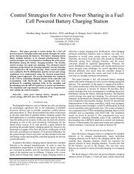
<strong>Design</strong> <strong>and</strong> <strong>testing</strong> <strong>of</strong> a <strong>fuel</strong>-<strong>cell</strong> <strong>powered</strong> <strong>battery</strong> <strong>charging</strong> <strong>station</strong><br />
Zhenhua Jiang, Roger A. Dougal *<br />
Department <strong>of</strong> Electrical Engineering, University <strong>of</strong> South Carolina, Columbia, SC 29208, USA<br />
Received 21 October 2002; accepted 4 December 2002<br />
Abstract<br />
The portable <strong>fuel</strong>-<strong>cell</strong> <strong>powered</strong> <strong>battery</strong> <strong>charging</strong> <strong>station</strong> provides a good solution to re<strong>charging</strong> batteries in field applications. This paper<br />
presents the design <strong>and</strong> <strong>testing</strong> <strong>of</strong> control strategies for this system using the Virtual Test Bed (VTB). The VTB provides a unique environment<br />
to model interdisciplinary components, to rapidly prototype the control system, <strong>and</strong> to simulate complex systems. In this paper, the system<br />
design is first proposed. Both static <strong>and</strong> real-time control strategies are investigated to coordinate the power distribution among batteries. The<br />
<strong>fuel</strong> <strong>cell</strong>, <strong>battery</strong> <strong>and</strong> power electronic system are modeled in the native VTB format. The <strong>charging</strong> controller is designed <strong>and</strong> implemented in<br />
MatLab/Simulink, <strong>and</strong> then is imported to VTB for system simulation. The <strong>fuel</strong>-<strong>cell</strong> <strong>powered</strong> <strong>battery</strong> <strong>charging</strong> <strong>station</strong> is simulated under the<br />
proposed <strong>charging</strong> algorithms. The performance <strong>of</strong> each <strong>charging</strong> algorithm is analyzed.<br />
# 2003 Elsevier Science B.V. All rights reserved.<br />
Keywords: Battery; Charging <strong>station</strong>; Fuel <strong>cell</strong>; Simulink; VTB<br />
1. Introduction<br />
Rechargeable batteries such as lithium ion <strong>cell</strong>s are<br />
playing an increasingly significant role in the utilization<br />
<strong>of</strong> portable electronic devices such as portable computers,<br />
<strong>cell</strong>ular phones <strong>and</strong> camcorders [1]. These batteries feature<br />
small size, light weight <strong>and</strong> renewable utilization in comparison<br />
to conventional primary batteries. These advantages,<br />
however, are restricted by their limited usable time. It is then<br />
necessary to develop some kind <strong>of</strong> portable <strong>battery</strong> <strong>charging</strong><br />
system. The <strong>fuel</strong> <strong>cell</strong>, which is emerging as one <strong>of</strong> the most<br />
promising technologies for the future power sources [2,3],<br />
may provide a good solution to powering the portable<br />
<strong>charging</strong> <strong>station</strong> that may be far away from the utility power<br />
system [4].<br />
Both the <strong>fuel</strong> <strong>cell</strong> <strong>and</strong> lithium ion <strong>battery</strong> are strongly<br />
nonlinear, <strong>and</strong> the <strong>fuel</strong> <strong>cell</strong> has a limited power capacity [5–8].<br />
These conditions present some difficulty for the system<br />
designer. Power converters are needed to condition the<br />
power flow <strong>and</strong> should be controlled appropriately. In order<br />
to meet the requirements to simultaneously charge multiple<br />
batteries, power converters are then connected in parallel,<br />
one for each <strong>battery</strong> pack. The initial states <strong>of</strong> charge <strong>of</strong> the<br />
various batteries may be different when they are inserted into<br />
the charger. A <strong>battery</strong> with a lower initial state <strong>of</strong> charge may<br />
* Corresponding author. Tel.: þ1-803-777-7890; fax: þ1-803-777-8045.<br />
E-mail address: dougal@engr.sc.edu (R.A. Dougal).<br />
require a larger <strong>charging</strong> current or otherwise a longer<br />
<strong>charging</strong> time. Therefore, the power from the <strong>fuel</strong> <strong>cell</strong> should<br />
be distributed efficiently among the batteries. The power<br />
distribution from a nonlinear <strong>and</strong> current-limited power<br />
source presents obvious difficulty for the design <strong>of</strong> control<br />
strategies. In order to reduce the development cycle <strong>and</strong><br />
costs, it is necessary to test the possible control strategies<br />
through simulation. The Virtual Test Bed (VTB) provides a<br />
good environment to model interdisciplinary components, to<br />
rapidly prototype the control system, <strong>and</strong> to simulate complex<br />
systems. The VTB allows h<strong>and</strong>ling natural power flow,<br />
signal <strong>and</strong> data coupling between devices <strong>of</strong> multi-disciplines<br />
<strong>and</strong> it <strong>of</strong>fers a combination <strong>of</strong> both topological <strong>and</strong> mathematical<br />
expressions in model formulation for a comprehensive<br />
<strong>and</strong> efficient modeling process. In addition, the VTB is<br />
endowed with mechanisms for importing models from several<br />
languages such as MatLab/Simulink, which was valuable<br />
during the control system design [9].<br />
In the following, the system architecture <strong>and</strong> the control<br />
issues are first described. Both static <strong>and</strong> real-time control<br />
strategies were investigated to coordinate the power distribution<br />
among the batteries. The <strong>fuel</strong> <strong>cell</strong>, <strong>battery</strong> <strong>and</strong> power<br />
electronic system were modeled in the native VTB form.<br />
The <strong>charging</strong> controller was designed <strong>and</strong> implemented in<br />
MatLab/Simulink <strong>and</strong> then imported to VTB for system<br />
simulation. Finally, the full <strong>fuel</strong>-<strong>cell</strong> <strong>powered</strong> <strong>battery</strong> <strong>charging</strong><br />
<strong>station</strong> was simulated as it used the proposed <strong>charging</strong><br />
algorithms.<br />
0378-7753/03/$ – see front matter # 2003 Elsevier Science B.V. All rights reserved.<br />
doi:10.1016/S0378-7753(02)00725-5
2 Z. Jiang, R.A. Dougal / Journal <strong>of</strong> Power Sources 5158 (2003) 1–9<br />
2. System design<br />
In general, the <strong>battery</strong> <strong>charging</strong> <strong>station</strong> should allow<br />
multiple batteries to be charged simultaneously <strong>and</strong> it should<br />
allow any <strong>battery</strong> to be inserted or retrieved at any time.<br />
While an arbitrary number <strong>of</strong> <strong>charging</strong> channels are possible,<br />
we used here three channels, which can represent the<br />
general solution to many <strong>charging</strong> channels. Since the<br />
objective <strong>of</strong> this work was to prove out the basic power<br />
sharing algorithms, we assume here that all three batteries<br />
are always in the charger. The case that some batteries are<br />
inserted or retrieved at r<strong>and</strong>om times will be reported later<br />
in [10].<br />
The block diagram <strong>of</strong> the proposed <strong>fuel</strong>-<strong>cell</strong> <strong>powered</strong><br />
<strong>battery</strong> <strong>charging</strong> <strong>station</strong> is shown in Fig. 1, where the system<br />
parameters are also shown. A <strong>fuel</strong> <strong>cell</strong> stack, which is the<br />
power generation system, is used to charge up to three<br />
lithium ion <strong>battery</strong> packs each through a dc/dc step-down<br />
power converter (buck converter). Each <strong>battery</strong> contains four<br />
series-connected lithium ion <strong>cell</strong>s. Each buck converter<br />
efficiently converts the <strong>fuel</strong> <strong>cell</strong> voltage to an appropriate<br />
lower voltage to charge the corresponding <strong>battery</strong>. By controlling<br />
the buck converters, the <strong>charging</strong> currents can be<br />
regulated. A controller is used to coordinate the power<br />
converters. The controller monitors the currents <strong>and</strong> voltages<br />
<strong>of</strong> the batteries <strong>and</strong> outputs the appropriate pulse-width<br />
modulation signals to the buck converters.<br />
From Fig. 1, it is clear that the power from the <strong>fuel</strong> <strong>cell</strong> is<br />
distributed among three batteries, which can be expressed in<br />
Eq. (1).<br />
P fc ¼ P 1 þ P 2 þ P 3 (1)<br />
where P 1 , P 2 , <strong>and</strong> P 3 are the power to three <strong>charging</strong><br />
channels, respectively, <strong>and</strong> P fc the power from the <strong>fuel</strong> <strong>cell</strong>.<br />
Fig. 1. Block diagram <strong>of</strong> the system design.<br />
In practice, the power distribution among the batteries is<br />
realized by regulating the <strong>charging</strong> currents <strong>of</strong> the batteries.<br />
The following equation relates the current from the <strong>fuel</strong> <strong>cell</strong><br />
to the three <strong>charging</strong> currents.<br />
I fc ¼ d 1 I 1 þ d 2 I 2 þ d 3 I 3 (2)<br />
where I 1 , I 2 , <strong>and</strong> I 3 are the currents to three batteries,<br />
respectively, I fc the current from the <strong>fuel</strong> <strong>cell</strong>, <strong>and</strong> d 1 , d 2 ,<br />
d 3 the duty cycles <strong>of</strong> the three buck converters, respectively,<br />
<strong>and</strong> they have values between 0 <strong>and</strong> 1.<br />
Since the <strong>fuel</strong> <strong>cell</strong> output current is limited, the sum <strong>of</strong> the<br />
right h<strong>and</strong> side in Eq. (2) should be less than some value (i.e.<br />
I max ). Considering that the variations in both the <strong>fuel</strong> <strong>cell</strong><br />
voltage <strong>and</strong> the <strong>battery</strong> voltages are not too large, the duty<br />
cycle <strong>of</strong> the switching signal to each buck converter will vary<br />
within a limited small range (for example, from 0.7 to 0.75).<br />
Based on this assumption, we can take the following expression<br />
as a criterion for active power distribution among the<br />
batteries.<br />
I 1 þ I 2 þ I 3 I lim (3)<br />
where I lim is a preset limit for the total <strong>charging</strong> current<br />
which can be estimated according to I max <strong>and</strong> the average<br />
duty cycle. Eq. (3) gives a basic requirement for the<br />
design <strong>of</strong> control strategies for active power sharing in this<br />
system.<br />
3. <strong>Design</strong> <strong>of</strong> <strong>charging</strong> algorithm<br />
The users may have different requirements in <strong>charging</strong><br />
the batteries according to their own needs. While some may<br />
require that the batteries be fully charged within the shortest<br />
period <strong>of</strong> time, others may wish to charge at a slower rate<br />
in order to increase the life expectancy <strong>of</strong> their batteries. In<br />
order to discover the most appropriate control schemes<br />
for the various requirements, three <strong>charging</strong> algorithms<br />
were investigated to coordinate the power distribution<br />
among the <strong>battery</strong> branches. These strategies were equal<br />
rate <strong>charging</strong>, proportional rate <strong>charging</strong>, <strong>and</strong> pulse current<br />
<strong>charging</strong>.<br />
Among these power sharing algorithms, Dc <strong>and</strong> pulse<br />
current <strong>charging</strong> protocols were used. dc <strong>charging</strong> protocol<br />
can help to protect the <strong>battery</strong> from over<strong>charging</strong>. Under this<br />
protocol, the <strong>battery</strong> is charged to an end potential using a<br />
constant current. The potential is then held constant after this<br />
potential is reached, <strong>and</strong> the <strong>charging</strong> current will taper<br />
gradually. The <strong>charging</strong> process will stop when the current<br />
reaches a preset small value during the constant voltage<br />
mode. Under pulse <strong>charging</strong> protocol, a pulse current with<br />
a period <strong>of</strong> T <strong>and</strong> on-time <strong>of</strong> T on is applied to the <strong>battery</strong>.<br />
Pulse current <strong>charging</strong> has been shown to enhance <strong>charging</strong><br />
rate capability <strong>and</strong> also prevent the increase <strong>of</strong> internal<br />
impedance <strong>of</strong> the <strong>battery</strong>, thus reducing the total <strong>charging</strong><br />
time [8].
Z. Jiang, R.A. Dougal / Journal <strong>of</strong> Power Sources 5158 (2003) 1–9 3<br />
3.1. Equal rate <strong>charging</strong><br />
When the initial states <strong>of</strong> charge <strong>of</strong> the batteries are close,<br />
a direct <strong>and</strong> simple approach to <strong>charging</strong> all the batteries<br />
using dc <strong>charging</strong> protocol is to distribute the <strong>charging</strong><br />
current equally among them. Due to the small differences<br />
in the initial states <strong>of</strong> the batteries, some batteries may reach<br />
the reference voltage earlier than others. When one <strong>battery</strong><br />
reaches its voltage limit, the voltage will be kept constant<br />
<strong>and</strong> the <strong>charging</strong> current will eventually taper to zero. The<br />
rest <strong>of</strong> the total available current will be re-distributed<br />
equally between the other batteries. Then the same scheme<br />
is followed by the remaining batteries till all batteries move<br />
to the constant voltage mode. This control strategy is illustrated<br />
in Fig. 2. This algorithm can be implemented easily<br />
but it may take a longer time for all batteries to become fully<br />
charged when the initial states <strong>of</strong> charge <strong>of</strong> the batteries are<br />
widely disparate.<br />
3.2. Proportional rate <strong>charging</strong><br />
A more time-efficient method that is suitable for batteries<br />
with any initial state <strong>of</strong> charge can take into consideration<br />
the fact that the charge that the <strong>battery</strong> will need to become<br />
fully charged is the integral <strong>of</strong> the <strong>charging</strong> current over the<br />
total <strong>charging</strong> time. The depth <strong>of</strong> discharge can be used to<br />
represent a measurement <strong>of</strong> the rest <strong>of</strong> the charge. It is<br />
calculated as unity minus state <strong>of</strong> charge. If constant currents<br />
<strong>of</strong> the same magnitude are applied to charge different batteries,<br />
the <strong>charging</strong> time will be proportional to the depth <strong>of</strong><br />
discharge (neglecting nonlinearity in the <strong>battery</strong>). On the<br />
other h<strong>and</strong>, if wewant all the batteries to become fully charged<br />
at the same time, the <strong>charging</strong> current can be proportional to<br />
the fraction <strong>of</strong> the depth <strong>of</strong> discharge <strong>of</strong> each <strong>battery</strong>, which<br />
can be calculated according to Eq. (4)<br />
1 SOC i<br />
I i ¼ I lim P 3<br />
i¼1 ð1 SOC ; i ¼ 1; ...; 3 (4)<br />
iÞ<br />
where I i is the <strong>charging</strong> current <strong>of</strong> the ith <strong>battery</strong>, I lim the total<br />
available <strong>charging</strong> current, <strong>and</strong> SOC i the state <strong>of</strong> charge <strong>of</strong><br />
the ith <strong>battery</strong>.<br />
Although the batteries may become fully charged almost<br />
simultaneously with this algorithm, it is difficult to estimate<br />
the state <strong>of</strong> charge. For Li-ion batteries, an approximate<br />
relationship between the state <strong>of</strong> charge (SOC) <strong>and</strong> open<br />
circuit voltage can be found when the SOC is not within the<br />
extreme range, i.e. if the SOC is between 0.1 <strong>and</strong> 0.9.<br />
Therefore, the SOC can be estimated by measuring the<br />
<strong>battery</strong> voltage. In this paper, the SOC is estimated according<br />
to a linear relationship, which is given in Eq. (5).<br />
SOC ¼ v 0 a<br />
þ c (5)<br />
b<br />
where a, b <strong>and</strong> c are constants <strong>and</strong> can be easily obtained by<br />
a series <strong>of</strong> experiments, v 0 is the <strong>battery</strong> open circuit voltage<br />
which can be estimated from the following equation.<br />
v ¼ v 0 þ ir (6)<br />
where v <strong>and</strong> i are the measured voltage <strong>and</strong> <strong>charging</strong> current<br />
<strong>of</strong> the <strong>battery</strong>, <strong>and</strong> r the equivalent series resistance <strong>of</strong> the<br />
<strong>battery</strong>.<br />
3.3. Pulse current <strong>charging</strong><br />
Besides the dc <strong>charging</strong>, the third method is pulse current<br />
<strong>charging</strong>. Under this algorithm, three pulse currents with the<br />
same period <strong>of</strong> T <strong>and</strong> different on-times are applied to the<br />
batteries alternately. The sum <strong>of</strong> the on-time <strong>of</strong> each pulse is<br />
equal to the period <strong>of</strong> the pulses. The illustration <strong>of</strong> this<br />
control strategy is given in Fig. 3. A similar method as the<br />
proportional rate <strong>charging</strong> can be found for pulse <strong>charging</strong>.<br />
The duty cycles <strong>of</strong> pulse <strong>charging</strong> currents can be proportional<br />
to the fraction <strong>of</strong> the depth <strong>of</strong> discharge <strong>of</strong> each<br />
<strong>battery</strong>, which can be estimated according to the following<br />
equation.<br />
1 SOC i<br />
D i ¼ P 3<br />
i¼1 ð1 SOC ; i ¼ 1; ...; 3 (7)<br />
iÞ<br />
where D i is the duty cycle <strong>of</strong> the <strong>charging</strong> current <strong>of</strong> the ith<br />
<strong>battery</strong>,<br />
With this algorithm, the <strong>charging</strong> current can be larger<br />
than that in the previous algorithms because only one <strong>battery</strong><br />
is charged at any time. It is also possible for all batteries to be<br />
Fig. 2. Illustration <strong>of</strong> equal rate <strong>charging</strong> algorithm with three batteries each starting at different initial state <strong>of</strong> charge.
4 Z. Jiang, R.A. Dougal / Journal <strong>of</strong> Power Sources 5158 (2003) 1–9<br />
Fig. 3. Illustration <strong>of</strong> pulse current <strong>charging</strong> algorithm.<br />
fully charged almost simultaneously; nevertheless the disadvantage<br />
is that it is difficult to implement this algorithm in<br />
the control system because it involves a lot <strong>of</strong> dynamics.<br />
4. Component modeling<br />
The VTB supports both native <strong>and</strong> imported model formulations:<br />
the native model is constructed using the resistive<br />
companion method [11], <strong>and</strong> the controller model implemented<br />
in Simulink can be imported to VTB. This Simulink<br />
model can be used in either <strong>of</strong> two ways. First, when the<br />
controller is still in development, the Simulink model can be<br />
used in an interactive co-simulation mode that allows adjustment<br />
<strong>of</strong> the controller parameters during system simulation.<br />
Second, once the controller design has been finalized, the<br />
controller model can be compiled into an executable that<br />
allows others to study the system behavior without having to<br />
actually run Matlab or Simulink.<br />
The native models for the <strong>fuel</strong> <strong>cell</strong>, <strong>battery</strong> <strong>and</strong> power<br />
electronic system, as well as the VTB–Simulink interface,<br />
are available in the current version <strong>of</strong> VTB. In this section,<br />
the model description <strong>of</strong> the <strong>fuel</strong> <strong>cell</strong>, <strong>battery</strong> <strong>and</strong> power<br />
converter, <strong>and</strong> the Simulink implementation <strong>of</strong> the <strong>charging</strong><br />
controller are described.<br />
4.1. Fuel <strong>cell</strong> system<br />
The electrochemical reaction process inside the <strong>fuel</strong> <strong>cell</strong><br />
stack is very complicated. In this application, we are particularly<br />
interested in the electrical characteristics on the<br />
electrodes. The thermal transfer by the material streams is<br />
negligible. The effects <strong>of</strong> water management on the performance<br />
are neglected. The air is consumed by the <strong>fuel</strong> <strong>cell</strong><br />
stack, <strong>and</strong> this is replaced by the consumption <strong>of</strong> the oxygen<br />
<strong>and</strong> the performance dependence on the partial pressure <strong>of</strong><br />
the oxygen when it is mixed with nitrogen. An empirical<br />
equation given in Eq. (8) is used to describe the potential <strong>of</strong> a<br />
<strong>fuel</strong> <strong>cell</strong> stack [12].<br />
<br />
I<br />
I<br />
V ¼ N <strong>cell</strong><br />
"E 0 bðTÞ log rðTÞ<br />
A <strong>cell</strong><br />
A <strong>cell</strong><br />
each <strong>cell</strong> (cm 2 ), T the bulk temperature <strong>of</strong> the stack (K), <strong>and</strong><br />
P the hydrogen pressure (Pa), b <strong>and</strong> r the functions <strong>of</strong> the<br />
temperature, <strong>and</strong> m <strong>and</strong> n the functions <strong>of</strong> the pressure.<br />
The expressions for b, r, m, <strong>and</strong> n are the polynomials that<br />
are calculated empirically from the experiment data.The<br />
mass flow <strong>of</strong> the hydrogen is simply proportional to the<br />
output current <strong>and</strong> the series number <strong>of</strong> the <strong>cell</strong>s, as shown<br />
below.<br />
_M ¼ N <strong>cell</strong> KI (9)<br />
where _M is the mass flow <strong>of</strong> the hydrogen, K the proportionality<br />
constant (mol/C).<br />
The difference between the total power from the reaction<br />
<strong>and</strong> the electrical power released is the thermal power that<br />
must be expelled from the <strong>fuel</strong> <strong>cell</strong> stack. The thermal power<br />
is given by<br />
<br />
Q ¼ N <strong>cell</strong><br />
DH<br />
nF<br />
<br />
I VI (10)<br />
where Q is the thermal power expelled from the <strong>fuel</strong> <strong>cell</strong><br />
stack, DH the change <strong>of</strong> entropy <strong>of</strong> hydrogen, n the number<br />
<strong>of</strong> moles <strong>of</strong> hydrogen, <strong>and</strong> F the Faraday’s constant.<br />
4.2. Battery system<br />
The objective <strong>of</strong> modeling the <strong>battery</strong> system is to replicate<br />
the electrical <strong>and</strong> thermal properties <strong>of</strong> the <strong>battery</strong> as<br />
it interacts with the external circuit. In this application, all<br />
electrochemical reactions are considered uniform throughout<br />
each porous electrode <strong>and</strong> all spatial variations <strong>of</strong> chemical<br />
concentrations <strong>and</strong> potentials are ignored. The model is<br />
obtained by fitting the data from manufacturers’ data sheets<br />
or independent measurements. The equivalent electrical<br />
schematic <strong>of</strong> the model is shown in Fig. 4.<br />
The equivalent model comprises three components: an<br />
equilibrium potential E, an internal resistance that is divided<br />
into two components R 1 <strong>and</strong> R 2 , <strong>and</strong> an effective capacitance<br />
C that represents localized storage <strong>of</strong> chemical energy<br />
within the porous electrodes. The equilibrium potential <strong>of</strong><br />
the <strong>battery</strong> depends on the temperature <strong>and</strong> the amount <strong>of</strong><br />
active material available in the electrodes, which can be<br />
specified in terms <strong>of</strong> depth <strong>of</strong> discharge. The potential E, the<br />
# I<br />
mðPÞ exp nðPÞ<br />
(8)<br />
A <strong>cell</strong><br />
where E 0 is the st<strong>and</strong>ard potential <strong>of</strong> H 2 –O 2 reaction, I the<br />
current from the <strong>fuel</strong> <strong>cell</strong> (mA), V the voltage <strong>of</strong> the stack<br />
(mV), N <strong>cell</strong> the series number <strong>of</strong> the <strong>cell</strong>s, A <strong>cell</strong> the area <strong>of</strong><br />
Fig. 4. Equivalent circuit <strong>of</strong> Li-ion <strong>battery</strong> based on the experimental data.
terminal voltage v <strong>and</strong> the depth <strong>of</strong> discharge DOD are<br />
related by Eqs. (11)–(13).<br />
Z. Jiang, R.A. Dougal / Journal <strong>of</strong> Power Sources 5158 (2003) 1–9 5<br />
iðtÞ ¼ 1 R 2<br />
½vðtÞ E½iðtÞ; TðtÞ; tŠ R 1 iðtÞŠ þ C d dt ½vðtÞ<br />
E½iðtÞ; TðtÞ; tŠ R 1 iðtÞŠ (11)<br />
v½iðtÞ; TðtÞ; tŠ ¼ XN<br />
j¼0<br />
c j DOD j ½iðtÞ; TðtÞ; tŠþDE½TðtÞŠ (12)<br />
DOD½iðtÞ; TðtÞ; tŠ ¼ 1 Z t<br />
a½iðtÞŠb½TðtÞŠiðtÞ dt (13)<br />
Q r<br />
0<br />
where i is the <strong>battery</strong> current (A), N the highest order <strong>of</strong> the<br />
fitting polynomial <strong>of</strong> the reference curve, c j the coefficient<br />
<strong>of</strong> the jth order term in the polynomial representation, Q r<br />
the <strong>battery</strong> capacity referred to the cut-<strong>of</strong>f voltage for the<br />
reference curve (Ah), T the <strong>battery</strong> temperature (K), <strong>and</strong> t the<br />
independent time variable (s). A potential correction term<br />
DE(T) is used to compensate for the variation <strong>of</strong> equilibrium<br />
potential that is induced by the temperature change at the<br />
reference rate. The dependence <strong>of</strong> the depth <strong>of</strong> discharge on<br />
the rate is accounted for by a factor a(i). A factor b(T) is used<br />
to account for the dependence <strong>of</strong> the depth <strong>of</strong> discharge<br />
on the temperature. The detail <strong>of</strong> how to determine these<br />
parameters can be found in [13].<br />
The change <strong>of</strong> the <strong>battery</strong> temperature is characterized by<br />
the thermal energy balance [14] equation that is described by<br />
Eq. (14). Heat generation due to entropy change or phase<br />
change, changes in the heat capacity are ignored without<br />
apparent loss <strong>of</strong> model accuracy.<br />
mc p<br />
dTðtÞ<br />
dt<br />
¼ iðtÞ 2 R 1 þ 1 R 2<br />
½vðtÞ E½iðtÞ; TðtÞ; tŠ iðtÞR 1 Š 2<br />
h c A½TðtÞ T a Š (14)<br />
where A is the <strong>battery</strong> external surface area (m 2 ), c p the<br />
specific heat <strong>of</strong> the <strong>battery</strong> pack (J/(kg K)), h c the heat<br />
transfer coefficient (W/(m 2 K)), m the mass <strong>of</strong> the <strong>battery</strong><br />
(kg), <strong>and</strong> T a is the ambient temperature (K).<br />
4.3. Power electronic system<br />
As mentioned before, each <strong>battery</strong> is charged by an<br />
individual buck converter. Fig. 5 shows the simplified power<br />
circuit for one <strong>of</strong> three <strong>charging</strong> channels, in which an<br />
MOSFET transistor <strong>and</strong> a power diode chop the input dc<br />
voltage to a pulse voltage, the power inductor filters the output<br />
current, <strong>and</strong> the capacitor smoothes the output voltage. The<br />
output <strong>of</strong> the buck converter is a smooth dc voltage. The power<br />
electronic system in the <strong>battery</strong> <strong>charging</strong> <strong>station</strong> is constructed<br />
by three such power converters that are connected in parallel.<br />
They have the same power source (the <strong>fuel</strong> <strong>cell</strong>) but difference<br />
loads (the batteries).<br />
Since the goal <strong>of</strong> the system level simulation is to<br />
investigate the power balance in the <strong>fuel</strong> <strong>cell</strong>/<strong>battery</strong> system<br />
Fig. 5. Schematic <strong>of</strong> the simplified power circuit for one <strong>charging</strong> channel.<br />
<strong>and</strong> to monitor the main parameters <strong>of</strong> the system, the<br />
simulation time step can be long, for example, higher than<br />
1 s. In this case, a time-average model <strong>of</strong> the converter is used,<br />
<strong>and</strong> both the switching transients <strong>and</strong> the harmonic effects are<br />
neglected. The power flow in the converter is controlled by<br />
adjusting the average on/<strong>of</strong>f duty cycle <strong>of</strong> the switching signal.<br />
The average output voltage <strong>of</strong> the buck converter is determined<br />
by the following equation.<br />
V o<br />
¼ t on<br />
V i T ¼ d (15)<br />
where V i <strong>and</strong> V o are the average input <strong>and</strong> output voltages <strong>of</strong><br />
the converter, respectively, t on the turn-on time <strong>of</strong> the switch<br />
during a period, T the switching period, <strong>and</strong> d the average<br />
duty cycle <strong>of</strong> the switching signal.<br />
4.4. Charging controller<br />
Since the VTB provides a mechanism for importing<br />
models from Simulink <strong>and</strong> co-simulating with MatLab,<br />
the control algorithm can be rapidly prototyped in Simulink.<br />
The Simulink model <strong>of</strong> the charge controller is shown in<br />
Fig. 6. The voltages <strong>and</strong> <strong>charging</strong> currents <strong>of</strong> three batteries<br />
are input from VTB through six input terminals. The reference<br />
<strong>charging</strong> current for each <strong>battery</strong> <strong>and</strong> the corresponding<br />
duty cycle for each power converter are calculated in the<br />
Simulink model. The Simulink model <strong>of</strong> the controller also<br />
determines the turn-on or -<strong>of</strong>f <strong>of</strong> the switch connected to<br />
each <strong>battery</strong>. The controller can output a turn<strong>of</strong>f signal when<br />
the <strong>charging</strong> stops or a fault is detected. The average values<br />
<strong>of</strong> the duty cycles <strong>and</strong> the switch states are exported to the<br />
VTB through six output terminals.<br />
The main functional blocks in the charge controller are the<br />
<strong>charging</strong> current strategy module, the current regulation<br />
module, the voltage regulation module, <strong>and</strong> the <strong>charging</strong><br />
termination decision module. The <strong>charging</strong> current strategy<br />
module is developed based on the proposed three power<br />
sharing algorithms. The reference <strong>charging</strong> current for each<br />
<strong>battery</strong> is calculated in this module.<br />
The current <strong>and</strong> voltage regulation modules are used to<br />
compute the duty cycles to the buck converters according to<br />
the reference currents from the <strong>charging</strong> current strategy<br />
module <strong>and</strong> the reference voltages set up in this module,<br />
respectively. The classical proportional–integral approach<br />
is used to regulate the <strong>charging</strong> currents <strong>and</strong> voltages. The<br />
current <strong>and</strong> voltage regulation laws are formulated in
6 Z. Jiang, R.A. Dougal / Journal <strong>of</strong> Power Sources 5158 (2003) 1–9<br />
Fig. 6. Simulink model <strong>of</strong> the <strong>battery</strong> charge controller.<br />
Eqs. (16) <strong>and</strong> (17), respectively.<br />
Z<br />
d ¼ d old þ k pi ðI ref IÞþk ii ðI ref IÞ dt (16)<br />
d ¼ d old þ k pv ðV ref<br />
VÞþk iv<br />
Z<br />
ðV ref VÞ dt (17)<br />
where V, I are the measured voltage <strong>and</strong> current <strong>of</strong> the<br />
<strong>battery</strong>, d <strong>and</strong> d old the current <strong>and</strong> previous duty cycles used<br />
to control the buck converter, V ref <strong>and</strong> I ref the reference<br />
voltage <strong>and</strong> <strong>charging</strong> current <strong>of</strong> the <strong>battery</strong>, k pi , k ii , <strong>and</strong> k pv ,<br />
k iv are the proportional <strong>and</strong> integral gains for current <strong>and</strong><br />
voltage regulations, respectively.<br />
The <strong>charging</strong> termination decision module can determine<br />
when the <strong>charging</strong> process stops <strong>and</strong> output a turn<strong>of</strong>f signal<br />
to the corresponding power converter as the <strong>charging</strong> termination<br />
happens.<br />
5. System simulation<br />
In order to investigate the performance <strong>of</strong> the system<br />
together with the charge controller, the <strong>fuel</strong>-<strong>cell</strong> <strong>powered</strong><br />
<strong>battery</strong> <strong>charging</strong> <strong>station</strong> was assembled in the VTB <strong>and</strong><br />
the simulation study was conducted under three proposed
Z. Jiang, R.A. Dougal / Journal <strong>of</strong> Power Sources 5158 (2003) 1–9 7<br />
Fig. 7. Schematic view <strong>of</strong> the proposed <strong>fuel</strong>-<strong>cell</strong> <strong>powered</strong> <strong>battery</strong> <strong>charging</strong> <strong>station</strong>.<br />
<strong>charging</strong> algorithms. Fig. 7 shows the VTB schematic view<br />
<strong>of</strong> the system shown in Fig. 1. The VTB model for the<br />
system consists mainly <strong>of</strong> a PEM <strong>fuel</strong> <strong>cell</strong> system, three buck<br />
converters, three lithium ion batteries, <strong>and</strong> a charge controller.<br />
The primary component <strong>of</strong> the <strong>fuel</strong> <strong>cell</strong> system is a<br />
<strong>fuel</strong> <strong>cell</strong> stack. The <strong>cell</strong> number is 25 <strong>and</strong> the nominal opencircuit<br />
voltage is 25.0 V. A hydrogen tank is connected to<br />
the stack to supply hydrogen for the <strong>fuel</strong> <strong>cell</strong>. The thermal<br />
source is used to exchange the heat <strong>of</strong> the <strong>fuel</strong> <strong>cell</strong> stack<br />
with the ambient. Assume here that the air is sufficient <strong>and</strong><br />
that the air consumed by the <strong>fuel</strong> <strong>cell</strong> is not regulated. The<br />
<strong>fuel</strong> <strong>cell</strong> stack is connected to the power bus through a lowpass<br />
filter. The power circuit for each <strong>charging</strong> channel<br />
consists <strong>of</strong> an average-value buck converter model <strong>and</strong> a<br />
low-pass filter. Each <strong>battery</strong> is an array <strong>of</strong> 4 1 (series by<br />
parallel connections) lithium ion <strong>cell</strong>s <strong>and</strong> is charged by an<br />
individual power converter. For convenience <strong>of</strong> demonstration,<br />
the batteries are numbered #1–3. The initial states <strong>of</strong><br />
charge <strong>of</strong> batteries #1–3 are 0.60, 0.50, <strong>and</strong> 0.40, respectively.<br />
The power diodes are used to prevent the power from<br />
flowing in the opposite direction. The charge controller is<br />
implemented in the Simulink model as shown in Fig. 6, <strong>and</strong><br />
imported to VTB for system simulation.<br />
The conditions <strong>of</strong> the <strong>charging</strong> algorithms are explained<br />
as follows. The total available <strong>charging</strong> current for both equal<br />
rate <strong>charging</strong> algorithm <strong>and</strong> proportional rate <strong>charging</strong> algorithm<br />
is set to 2.0 A. The <strong>charging</strong> process stops when the<br />
<strong>charging</strong> current tapers below 0.1 A during constant voltage<br />
mode. The <strong>charging</strong> current <strong>of</strong> the pulse current <strong>charging</strong><br />
algorithm is 1.4 A. The <strong>charging</strong> process stops when the<br />
<strong>battery</strong> voltage exceeds the reference voltage during lowvalue<br />
interval <strong>of</strong> the pulse. The simulated <strong>charging</strong> currents<br />
<strong>and</strong> states <strong>of</strong> charge <strong>of</strong> the batteries under these three <strong>charging</strong><br />
algorithms are shown in Fig. 8a–f, respectively.<br />
As shown in Fig. 8a, with the equal rate <strong>charging</strong> algorithm,<br />
each <strong>battery</strong> is charged at the same current with the<br />
magnitude <strong>of</strong> 0.67 A. It is seen that <strong>battery</strong> #1 needs about<br />
70 min to become full. The <strong>charging</strong> time <strong>of</strong> <strong>battery</strong> #1 under<br />
this algorithm is the shortest among three algorithms, as<br />
shown in Fig. 8. It takes 100 min for <strong>battery</strong> #3 to be fully<br />
charged. The <strong>charging</strong> time <strong>of</strong> <strong>battery</strong> #3 is the longest<br />
among these algorithms.
8 Z. Jiang, R.A. Dougal / Journal <strong>of</strong> Power Sources 5158 (2003) 1–9<br />
Fig. 8. Simulation results under three <strong>charging</strong> algorithms. (a–b) Equal rate <strong>charging</strong>; (c–d) proportional rate <strong>charging</strong>; (e–f) pulse current <strong>charging</strong>.
Z. Jiang, R.A. Dougal / Journal <strong>of</strong> Power Sources 5158 (2003) 1–9 9<br />
In Fig. 8c, it is shown that the <strong>charging</strong> current <strong>of</strong> each<br />
<strong>battery</strong> varies with the <strong>battery</strong> voltage <strong>and</strong> thus with the<br />
estimated SOC under the proportional rate <strong>charging</strong> algorithm.<br />
The <strong>battery</strong> with the lowest SOC is charged at the<br />
highest rate. It is clear that all the batteries reach the constant<br />
voltage mode almost simultaneously. The <strong>charging</strong> times <strong>of</strong><br />
three batteries are 78, 88, <strong>and</strong> 96 min, respectively.<br />
With the pulse current <strong>charging</strong> algorithm, the duty cycle<br />
<strong>of</strong> each pulse current also varies with the estimated SOC, as<br />
shown in Fig. 8e. The <strong>battery</strong> with the lowest SOC is charged<br />
by a pulse current with the largest duty cycle. Fig. 8e also<br />
shows that all the batteries become full almost simultaneously.<br />
The <strong>charging</strong> time for all batteries to be fully<br />
charged is 75 min, which is the shortest among three algorithms.<br />
From the simulation results, the following conclusions<br />
can be drawn for the proposed three <strong>charging</strong> algorithms:<br />
(1) The equal rate <strong>charging</strong> algorithm requires the shortest<br />
<strong>charging</strong> time for the <strong>battery</strong> with the highest initial<br />
SOC but the longest <strong>charging</strong> time for the <strong>battery</strong> with<br />
the lowest initial SOC among these algorithms.<br />
(2) All the batteries can move to the constant voltage mode<br />
almost simultaneously with the proportional rate<br />
<strong>charging</strong> algorithm.<br />
(3) All the batteries can become full almost simultaneously<br />
with pulse current <strong>charging</strong> algorithm. The <strong>charging</strong><br />
time for all the batteries to be fully charged with this<br />
algorithm is the minimum among these algorithms.<br />
6. Conclusions<br />
This paper presents an approach to the design <strong>and</strong> <strong>testing</strong><br />
<strong>of</strong> a <strong>fuel</strong>-<strong>cell</strong> <strong>powered</strong> <strong>battery</strong> <strong>charging</strong> <strong>station</strong> using the<br />
Virtual Test Bed. In this paper, the system design is first<br />
proposed. Both static <strong>and</strong> real-time control strategies are<br />
investigated to coordinate the power distribution among<br />
batteries. Interdisciplinary models such as the <strong>fuel</strong> <strong>cell</strong><br />
<strong>and</strong> <strong>battery</strong> system <strong>and</strong> the model <strong>of</strong> the power converter<br />
are developed natively in VTB. The control system is<br />
modeled in MatLab/Simulink <strong>and</strong> then imported into<br />
VTB. Based on the native <strong>and</strong> imported models, the <strong>fuel</strong><strong>cell</strong><br />
<strong>powered</strong> <strong>battery</strong> <strong>charging</strong> <strong>station</strong> is simulated under the<br />
proposed <strong>charging</strong> algorithms. The performance <strong>of</strong> each<br />
<strong>charging</strong> algorithm is analyzed.<br />
The following conclusions were drawn for the proposed<br />
three <strong>charging</strong> algorithms. The equal rate <strong>charging</strong> algorithm<br />
has the minimum <strong>charging</strong> time for the <strong>battery</strong> with<br />
the highest initial SOC but the longest <strong>charging</strong> time for<br />
the <strong>battery</strong> with the lowest initial SOC among these algorithms.<br />
It is easiest to implement this algorithm in practical<br />
controller hardware. With proportional rate <strong>charging</strong> algorithm,<br />
all the batteries can move to the constant voltage<br />
mode almost simultaneously. The pulse current <strong>charging</strong><br />
algorithm requires the minimum <strong>charging</strong> time for all the<br />
batteries but the algorithm is most difficult to implement.<br />
From the studies in this paper, it can be seen that the<br />
VTB is an effective computational environment for virtualprototyping<br />
multidisciplinary systems <strong>and</strong> studying the<br />
dynamic performances <strong>of</strong> complex systems.<br />
Acknowledgements<br />
This work was supported by the US Army CECOM <strong>and</strong><br />
the NRO under contract NRO-00-C-0134, <strong>and</strong> US ONR<br />
under contract N00014-00-1-0368.<br />
References<br />
[1] R.J. Brodd, Overview: rechargeable <strong>battery</strong> systems, in: Proceedings<br />
<strong>of</strong> the WESCON’93 Conference, 1993, pp. 206–209.<br />
[2] B. Rohl<strong>and</strong>, J. Nitsch, H. Wendt, Hydrogen <strong>and</strong> <strong>fuel</strong> <strong>cell</strong>s—the clean<br />
energy system, J. Power Sources 37 (1/2) (1992) 271–277.<br />
[3] A. Heinzel, C. Hebling, M. Müller, M. Zedda, C. Müller, Fuel <strong>cell</strong>s<br />
for low power applications, J. Power Sources 105 (2) (2002) 148–153.<br />
[4] Z. Jiang, R.A. Dougal, Control design <strong>and</strong> <strong>testing</strong> <strong>of</strong> a novel <strong>fuel</strong>-<strong>cell</strong><br />
<strong>powered</strong> <strong>battery</strong> <strong>charging</strong> <strong>station</strong>, in: Proceedings <strong>of</strong> IEEE Applied<br />
Power Electronics Conference, Miami, FL, 9–13 February 2003.<br />
[5] M.M. Bernardi, M.W. Verbrugge, A mathematical model <strong>of</strong> the<br />
solid-polymer-electrolyte <strong>fuel</strong> <strong>cell</strong>, J. Electrochem. Soc. 139 (9)<br />
(1992) 2477–2491.<br />
[6] J. Kim, S.-M. Lee, S. Srinivasan, Modeling <strong>of</strong> proton exchange<br />
membrane <strong>fuel</strong> <strong>cell</strong> performance with an empirical equation, J.<br />
Electrochem. Soc. 142 (8) (1995) 2670–2674.<br />
[7] L. Song, J.W. Evans, Electrochemical–thermal model <strong>of</strong> lithium<br />
polymer batteries, J. Electrochem. Soc. 147 (6) (2000) 2086–2095.<br />
[8] J. Li, E. Murphy, J. Winnick, P.A. Kohl, The effects <strong>of</strong> pulse <strong>charging</strong><br />
on cycling characteristics <strong>of</strong> commercial lithium-ion batteries, J.<br />
Power Sources 102 (1/2) (2001) 302–309.<br />
[9] R.A. Dougal, T. Lovett, A. Monti, E. Santi, A multilanguage<br />
environment for interactive simulation <strong>and</strong> development <strong>of</strong> controls<br />
for power electronics, in: Proceedings <strong>of</strong> the IEEE Power Electronics<br />
Specialists Conference, Vancouver, Canada, 17–22 June 2001.<br />
[10] Z. Jiang, R.A. Dougal, <strong>Design</strong>, rapid prototyping, <strong>and</strong> <strong>testing</strong> <strong>of</strong> a<br />
portable <strong>fuel</strong>-<strong>cell</strong> <strong>powered</strong> <strong>battery</strong> <strong>charging</strong> <strong>station</strong>, in: Proceedings<br />
<strong>of</strong> the IEEE Power Electronics Specialist Conference, Acapulco,<br />
Mexico, 2003.<br />
[11] D.A. Calahan, Computer-Aided Network <strong>Design</strong>, revised ed.,<br />
McGraw-Hill, New York, 1972.<br />
[12] G. Squadrito, G. Maggio, E. Passalacqua, F. Lufrano, A. Patti, An<br />
empirical equation for polymer electrolyte <strong>fuel</strong> <strong>cell</strong> (PEFC) behavior,<br />
J. Appl. Electrochem. 29 (1999) 1449–1455.<br />
[13] L. Gao, S. Liu, R.A. Dougal, Dynamic lithium-ion <strong>battery</strong> model for<br />
system simulation, IEEE Transactions on Components <strong>and</strong> Packaging,<br />
in press.<br />
[14] D. Bernardi, E. Pawlikowski, J. Newman, A general energy balance<br />
for <strong>battery</strong> systems, J. Electrochem. Soc. 132 (1) (1985) 5–12.