Technical Report - the Marine Advanced Technology Education ...
Technical Report - the Marine Advanced Technology Education ...
Technical Report - the Marine Advanced Technology Education ...

Create successful ePaper yourself
Turn your PDF publications into a flip-book with our unique Google optimized e-Paper software.
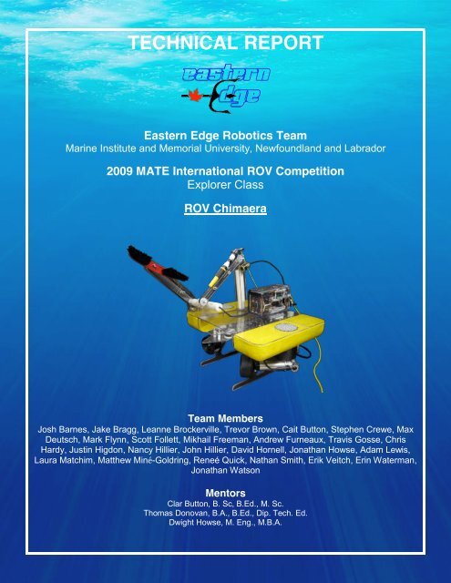
TECHNICAL REPORT<br />
Eastern Edge Robotics Team<br />
<strong>Marine</strong> Institute and Memorial University, Newfoundland and Labrador<br />
2009 MATE International ROV Competition<br />
Explorer Class<br />
ROV Chimaera<br />
Team Members<br />
Josh Barnes, Jake Bragg, Leanne Brockerville, Trevor Brown, Cait Button, Stephen Crewe, Max<br />
Deutsch, Mark Flynn, Scott Follett, Mikhail Freeman, Andrew Furneaux, Travis Gosse, Chris<br />
Hardy, Justin Higdon, Nancy Hillier, John Hillier, David Hornell, Jonathan Howse, Adam Lewis,<br />
Laura Matchim, Mat<strong>the</strong>w Miné-Goldring, Reneé Quick, Nathan Smith, Erik Veitch, Erin Waterman,<br />
Jonathan Watson<br />
Mentors<br />
Clar Button, B. Sc, B.Ed., M. Sc.<br />
Thomas Donovan, B.A., B.Ed., Dip. Tech. Ed.<br />
Dwight Howse, M. Eng., M.B.A.
2<br />
ABSTRACT<br />
This technical report describes <strong>the</strong> ROV Chimaera, built by <strong>the</strong> Eastern Edge Robotics<br />
Team to compete in <strong>the</strong> 2009 MATE International ROV Competition. Chimaera was designed to<br />
perform tasks relevant to submarine rescue, such as mating to a submarine's escape hatch and<br />
delivery of Emergency Life Support System (ELSS) pods. The process of building <strong>the</strong> ROV and<br />
traveling to <strong>the</strong> MATE Competition cost approximately $50,000, including <strong>the</strong> value of donated<br />
materials. Two pontoons connected by a Lexan TM frame form <strong>the</strong> basis of <strong>the</strong> chassis, which<br />
integrates six 48V thrusters and three high quality, low-light PCB cameras. Also incorporated are<br />
four main payload tools: an ABS ring with a clear Lexan TM cap, guides and legs for opening <strong>the</strong><br />
ELSS hatch and RORV mating, a too<strong>the</strong>d conveyer belt for collection of <strong>the</strong> ELSS pods, a<br />
magnetically coupled timing belt for delivery of <strong>the</strong> airline, and a belt-driven rotary brush for<br />
manipulation of <strong>the</strong> air valve. The control system was programmed in C# and runs using eight<br />
threads that sample data continuously. The ROV has an onboard electronics system that is inside<br />
polycarbonate housing connected to <strong>the</strong> surface using a custom-built te<strong>the</strong>r. The topsides<br />
electronics consists of a joystick and a control unit. A major innovation this year was <strong>the</strong> building of<br />
our own PIC embedded motor controllers for use with <strong>the</strong> payload tools. During this process, team<br />
members learned <strong>the</strong> importance of multiple points of view in solving a problem creatively, and <strong>the</strong><br />
benefits of working with people from many different disciplines.<br />
Figure 1. Eastern Edge Robotics Team, 2009.<br />
Left to Right: (back row) Justin Higdon, Jake Bragg, Mat<strong>the</strong>w Miné-Goldring, Steve Crewe, Cait<br />
Button, Josh Barnes, John Hillier, Nathan Smith, Jon Watson, Scott Follett, Andrew Furneaux;<br />
(front row) Dave Hornell, Leanne Brockerville, Erin Waterman, Jonathan Howse, Mark Flynn,<br />
Travis Gosse, Max Deutsch.
3<br />
TABLE OF CONTENTS<br />
ABSTRACT .................................................................................................................................................... 2<br />
TABLE OF CONTENTS .................................................................................................................................... 3<br />
1. BUDGET AND FINANCIAL STATEMENT ...................................................................................................... 4<br />
2. DESIGN RATIONALE .................................................................................................................................. 5<br />
2.1 Structural Frame .............................................................................................................................................................................................. 5<br />
2.2 Propulsion ........................................................................................................................................................................................................... 5<br />
2.3 Camera .................................................................................................................................................................................................................. 6<br />
2.4 Te<strong>the</strong>r .................................................................................................................................................................................................................... 6<br />
3. CONTROL SYSTEM .................................................................................................................................... 6<br />
3.1 Software Engineering ..................................................................................................................................................................................... 7<br />
3.2 Graphical User Interface ................................................................................................................................................................................ 7<br />
3.2.1 PreDive Checklist ................................................................................................................................................................................................7<br />
3.2.2 Control Panel .........................................................................................................................................................................................................7<br />
3.2.3 Navigation Window ............................................................................................................................................................................................8<br />
3.2.4 Power Control ........................................................................................................................................................................................................8<br />
3.2.5 Voltage and Current ...........................................................................................................................................................................................8<br />
3.2.6 Video Feed ...............................................................................................................................................................................................................8<br />
3.3 Motor Programming ....................................................................................................................................................................................... 9<br />
4. ELECTRONICS ........................................................................................................................................... 9<br />
4.1 Topside Control Unit ....................................................................................................................................................................................... 9<br />
4.2 Submarine Electronics Can ........................................................................................................................................................................ 10<br />
5. PAYLOAD TOOLS ..................................................................................................................................... 11<br />
5.1 Tool Motors ...................................................................................................................................................................................................... 11<br />
5.1.1 Motor Encapsulation ....................................................................................................................................................................................... 11<br />
5.1.2 Embedded Motor Controllers ...................................................................................................................................................................... 11<br />
5.2 Task 1: Survey and inspect <strong>the</strong> submarine for damage ................................................................................................................. 12<br />
5.3 Task 2: Pod posting ....................................................................................................................................................................................... 12<br />
5.4 Task 3: Ventilation ......................................................................................................................................................................................... 13<br />
5.5 Task 4: RORV Mating .................................................................................................................................................................................... 14<br />
6. CHALLENGES ........................................................................................................................................... 15<br />
7. TROUBLESHOOTING TECHNIQUES ........................................................................................................... 15<br />
8. FUTURE IMPROVEMENTS ........................................................................................................................ 16<br />
9. LESSONS LEARNED/SKILLS GAINED .......................................................................................................... 16<br />
10. DESCRIPTION OF A SUBMARINE RESCUE SYSTEM................................................................................... 17<br />
11. REFLECTIONS ON THE EXPERIENCE ........................................................................................................ 18<br />
12. TEAMWORK .......................................................................................................................................... 19<br />
13. ACKNOWLEDGEMENTS.......................................................................................................................... 20<br />
APPENDIX A ‐ FLOW ANALYSIS .................................................................................................................... 21<br />
APPENDIX B ‐ ELECTRICAL SCHEMATICS ....................................................................................................... 24<br />
APPENDIX C ‐ PROGRAMMING FLOW CHARTS ............................................................................................. 27
4<br />
1. BUDGET AND FINANCIAL STATEMENT<br />
Table 1: Total cost of materials and travel to competition.<br />
ITEM<br />
DONATIONS<br />
EXPENDITURES<br />
($CAD)<br />
($CAD)<br />
Polycarbonate electronics can 250.00<br />
Electronics housing 250.00<br />
Styrofoam 43.00<br />
Fiberglass and epoxy 270.00<br />
Hardware (fasteners, drill bits, etc.) 500.00<br />
Inuktun thrusters (6 x $ 2000) 12,000.00<br />
48V Maxon motors (6 x$516) 3100.00<br />
Fiber-optic te<strong>the</strong>r - LeoniElocab 1200.00<br />
Cameras (3 x $1500) 4500.00<br />
Analog input board 150.00<br />
Servo controller board 50.00<br />
Fiber-optic interface board – Focal<br />
3500.00<br />
Technologies - Moog<br />
Lexan polycarbonate sheet 250.00<br />
Printed Circuit Board production 200.00<br />
Pulse width modulators (6 x $250) 1500.00<br />
Misc. electronics components 300.00<br />
Pressure Sensor – Keller America 575.00<br />
Digital Compass 300.00<br />
SubConn Connectors 800.00<br />
Group airfare (15 people x $480) 7200.00<br />
Accommodations, meals, ground<br />
13,050.00<br />
transportation (15 people x $870)<br />
TOTAL $22,575.00 $27,413.00<br />
Table 2:Contributions to Eastern Edge Robotics.<br />
CONTRIBUTORS<br />
VALUE ($CAD)<br />
Faculty of Engineering, Memorial University 10,000.00<br />
<strong>Marine</strong> Institute 5000.00<br />
Department of Science, Memorial University 3000.00<br />
Summer Robotics Camps 3413.00<br />
Individual contributions (12 people @ $500.00 each) 6,000.00<br />
Donated materials 22,575.00<br />
TOTAL $49,988.00
5<br />
2. DESIGN RATIONALE<br />
2.1 Structural Frame<br />
The main structural components of Chimaera are two vertical H-framed skids, two buoyancy<br />
pontoons, and a Lexan TM polycarbonate sheet covering <strong>the</strong> top (Figure 2). These components<br />
were all designed using SolidWorks TM 3-D CAD to allow for sufficient buoyancy spacing for all <strong>the</strong><br />
required tools (Figure 3). The pontoons were milled from styrofoam using a Computer Numerical<br />
Control (CNC) router. The team <strong>the</strong>n laid up three layers of fiberglass around <strong>the</strong> styrofoam until it<br />
was uniform and structurally sound. This was performed in a boat-building workshop at <strong>the</strong> <strong>Marine</strong><br />
Institute specifically designed to allow fiberglass work without exposure to fumes to ensure safety<br />
of team members. A vertical thruster is located in a 10.16cm (4”) ABS tube in <strong>the</strong> center of each of<br />
<strong>the</strong>se pontoons.<br />
The H-frames were machined from 0.953cm (3/8") Lexan TM polycarbonate. The H-frame<br />
design was chosen because a large portion of its cross section is located far away from <strong>the</strong> neutral<br />
axis, thus providing large values of moment of inertia (I) and elastic section modulus (S). Since <strong>the</strong><br />
maximum stress (σ m ) is inversely proportional to S, it is practical for <strong>the</strong>se beams to be designed<br />
with a large S value according to <strong>the</strong> following relationship:<br />
m<br />
= M<br />
Where: σ m = maximum stress S<br />
M = first moment of <strong>the</strong> cross section about <strong>the</strong> neutral axis<br />
S = elastic section modulus<br />
The H-Frame allows <strong>the</strong> chassis to be structurally sound, relatively light, and hydrodynamic.<br />
Two horizontally mounted thrusters are attached to <strong>the</strong> outside of each H-frame as well as <strong>the</strong><br />
buoyancy pontoons on ei<strong>the</strong>r side and joined transversely by a 0.477cm (3/16”) Lexan TM sheet on<br />
top. This sheet supports <strong>the</strong> ROV transversely and is attached to <strong>the</strong> top of each buoyancy<br />
pontoon and H-frame. It also creates a strong platform on which multiple tools and equipment can<br />
be attached. The holes over <strong>the</strong> vertical thrusters were milled in <strong>the</strong> shape of honeycombs, which<br />
both protects <strong>the</strong> thrusters and allows for a more laminar flow of water.<br />
Figure 2. ROV Chimaera.<br />
Figure 3. Solidworks diagram of Chimaera.<br />
2.2 Propulsion<br />
Chimaera is driven by six 90 W Inuktun TM thrusters, each with a depth rating of 300m<br />
(Figure 4). The thrusters have standard EO connectors and are liquid filled with Enviro-Rite fluid<br />
for pressure compensation. Due to wear of brushes in <strong>the</strong> original motors, new compatible
6<br />
Maxon TM motors were purchased this year. These motors operate at 48V<br />
and 90W. As <strong>the</strong>se motors were ordered from Maxon TM directly, <strong>the</strong>y had<br />
to be modified to fit <strong>the</strong> Inuktun TM thruster mountings.<br />
First, <strong>the</strong> thrusters were disassembled and <strong>the</strong> motors removed.<br />
Four holes were drilled around <strong>the</strong> circumference of <strong>the</strong> motor shaft end<br />
and tapped for #6 bolts, which secured <strong>the</strong> motor to <strong>the</strong> thruster shaft<br />
end frame. A hole was also drilled through <strong>the</strong> motor shaft to allow it to<br />
be keyed to <strong>the</strong> shaft of <strong>the</strong> thruster. Before reassembling, all <strong>the</strong><br />
bearings and O-rings for each of <strong>the</strong> thrusters were inspected and<br />
lubricated appropriately. The motor wires were soldered back to <strong>the</strong><br />
thruster connector and <strong>the</strong> thrusters were <strong>the</strong>n pressure compensated<br />
with Enviro-Rite TM .<br />
2.3 Camera<br />
Figure 5. PCB camera.<br />
Figure 4. Inuktun TM thruster.<br />
Chimaera uses three high-quality (400 TVL), low-light (1.0<br />
Lux) Crystal Cam cameras (Figure 5). They are 0.635cm (1/4")<br />
color CCD cameras donated by Inuktun. The cameras have a<br />
3.6mm lens providing a 41° horizontal field of view. The cameras<br />
incorporate 12 high intensity LEDs for light. They are rated for<br />
use in up to 300m depth. A mounting bracket designed by <strong>the</strong><br />
team provides tilt control for <strong>the</strong> cameras.The three cameras are<br />
positioned as follows: one aft facing forward and down, one aft<br />
facing forward and up, and one side-facing mounted on <strong>the</strong><br />
starboard skid.<br />
2.4 Te<strong>the</strong>r<br />
A custom te<strong>the</strong>r designed by <strong>the</strong> team was donated by Leoni Elocab Inc. of Kitchener,<br />
Ontario, Canada. The outer portion of <strong>the</strong> te<strong>the</strong>r has a low drag polyurethane coating, designed to<br />
make <strong>the</strong> te<strong>the</strong>r neutrally buoyant in fresh water. The te<strong>the</strong>r has two 16-gauge copper wires to<br />
transmit DC power, and two multi-mode fiber optic strands for control and video signal<br />
transmission. One of <strong>the</strong> fibre optic strands is redundant and will only be used if <strong>the</strong> o<strong>the</strong>r is<br />
damaged.<br />
3. CONTROL SYSTEM<br />
Chimaera has a control system that was programmed using <strong>the</strong> C# language. The program is<br />
run on a notebook PC and uses DirectX to read user inputs and to provide drawing capabilities.<br />
The inputs from <strong>the</strong> joystick and mouse are monitored and appropriate output responses are<br />
calculated. The C# control system was designed as a multi-threaded program (i.e. using integrated<br />
segments), which can sample data continuously. The programming flow chart shows <strong>the</strong> logic<br />
behind <strong>the</strong> control system (Figure C1, Appendix C).<br />
The threads in <strong>the</strong> program are:<br />
• Analog/Digital Converter signal processing thread, for all sensors and power supply<br />
monitoring.<br />
• Joystick monitoring, to take in joystick information and update <strong>the</strong> thrusters and control<br />
system appropriately.
7<br />
• Thruster control, to send updated values to <strong>the</strong> thruster and motors.<br />
• Accelerometer thread, which reads and displays values for pitch, roll, and heading, as well<br />
as temperature within <strong>the</strong> submarine electronics can.<br />
• Graphical User Interface (GUI) thread, which updates <strong>the</strong> visual representation of <strong>the</strong> ROV,<br />
both on <strong>the</strong> computer screen and <strong>the</strong> video display.<br />
• Collections thread, responsible for taking updated values from o<strong>the</strong>r threads and bringing<br />
<strong>the</strong>m into <strong>the</strong> ROV software.<br />
• <strong>Report</strong> thread, which keeps detailed information on <strong>the</strong> status of <strong>the</strong> ROV and records <strong>the</strong><br />
values for post-mission debriefing and review.<br />
• Pressure sensor thread, which reads and displays values for external temperature and<br />
pressure, both of which are used to calculate depth.<br />
Thread design increases processing speed by utilizing multi-core or multiple processors and<br />
allowing multiple threads to run simultaneously. Resources need to be allocated carefully, as<br />
multiple threads trying to access <strong>the</strong> same resource or variable at <strong>the</strong> same time could corrupt <strong>the</strong><br />
information. Therefore, each physical device is dedicated to a single thread, and <strong>the</strong>re is no<br />
overlap in resources.<br />
3.1 Software Engineering<br />
The control software has a modular design based on Object-Oriented Programming (OOP)<br />
techniques. This approach allows for changes in <strong>the</strong> program's devices or settings by changing a<br />
single line of code. It also facilitates <strong>the</strong> development of a library of classes that can be used with<br />
any ROV that follows this design pattern. For example, to update <strong>the</strong> software for a new ROV, one<br />
would have to write a new subclass for <strong>the</strong> ROV class, <strong>the</strong> MotorController class, and <strong>the</strong><br />
ROVSystem class. New to <strong>the</strong> library this year is a SerialMotor class, which is <strong>the</strong> software domain<br />
for our PIC controlled tooling motors.<br />
3.2 Graphical User Interface<br />
The GUI is based on a windowed concept. The benefit of this design is that <strong>the</strong> information<br />
displayed to <strong>the</strong> pilot is sectioned into manageable windows that can be opened or closed when<br />
needed. They can also be resized and arranged according to <strong>the</strong> pilot’s preference.<br />
3.2.1 Pre-Dive Checklist<br />
Before <strong>the</strong> Control Panel is accessible to <strong>the</strong> user, <strong>the</strong> Pre-Dive Checklist must be<br />
completed (Figure 6). This ensures that all safety and runtime checks are finished before launching<br />
<strong>the</strong> ROV. Several of <strong>the</strong> checks have been automated, such as <strong>the</strong> testing of thruster control; this<br />
is displayed to <strong>the</strong> user in a window box. The remaining items on <strong>the</strong> checklist are <strong>the</strong>n read aloud<br />
by <strong>the</strong> pilot before <strong>the</strong> ROV is launched to confirm that all safety issues are addressed. The<br />
checklist also has a command line parameter override, which allows <strong>the</strong> checklist to be disabled for<br />
debugging purposes.<br />
3.2.2 Control Panel<br />
Once <strong>the</strong> pre-dive checklist has been completed successfully, <strong>the</strong> control software is<br />
launched, displaying <strong>the</strong> main control panel (Figure 7). From <strong>the</strong> control panel <strong>the</strong> pilot can bring<br />
up any of <strong>the</strong> o<strong>the</strong>r windows; <strong>the</strong>se include navigation, power control, voltage and current readings,<br />
and <strong>the</strong> video feeds from <strong>the</strong> ROV.
8<br />
In addition, a GUI configuration tab can be displayed from <strong>the</strong> control panel; this allows for<br />
manual setting of <strong>the</strong> serial port assignments and individual scaling of <strong>the</strong> thruster power on <strong>the</strong><br />
ROV. This is an important tool for <strong>the</strong> accommodation of power differences in <strong>the</strong> thrusters that<br />
may occur with use.<br />
Figure 6. Pre-Dive Checklist.<br />
Figure 7. Control Panel.<br />
3.2.3 Navigation Window<br />
The navigation window displays <strong>the</strong> ROV’s heading as well as <strong>the</strong> false horizon to <strong>the</strong> pilot<br />
(Figure 8). Integrated into <strong>the</strong> compass is a turn counter that reads <strong>the</strong> number and direction of<br />
turns that have been made by <strong>the</strong> ROV. This information helps <strong>the</strong> pilot prevent excessive twisting<br />
of <strong>the</strong> te<strong>the</strong>r.<br />
3.2.4 Power Control<br />
In order to provide more accurate control for intricate tasks, a power gauge has been<br />
implemented. Using pulse width modulators, <strong>the</strong> power to all thrusters can be adjusted as a<br />
percentage from <strong>the</strong> GUI (Figure 9). Each thruster can also be scaled individually to accommodate<br />
small variations in thrust.<br />
Figure 8. Navigation Window.<br />
Figure 9. Power Control.<br />
F<br />
i<br />
g<br />
u<br />
r<br />
e<br />
3.2.5 Voltage and Current<br />
1<br />
.<br />
Voltage and current readings of <strong>the</strong> ROV are displayed to <strong>the</strong> user in this window (Figure<br />
10). The readings are sent from voltage sensors in <strong>the</strong> submarine electronics can and<br />
N<br />
current<br />
a<br />
sensors in <strong>the</strong> topsides unit.<br />
v<br />
3.2.6 Video Feed<br />
i<br />
g<br />
The video feeds from Chimaera are sent directly to <strong>the</strong> control software on a notebook<br />
a<br />
computer (Figure 11). This is in contrast to previous years, when <strong>the</strong> video feeds were displayed<br />
t<br />
i<br />
o<br />
n
9<br />
on a standard TV video screen via RCA cables. The new setup allows fur<strong>the</strong>r customization by <strong>the</strong><br />
pilot in <strong>the</strong> form of window overlays and resizing.<br />
Figure 10. Voltage and Current window.<br />
Figure 11. Video Feed.<br />
3.3 Motor Programming<br />
Chimaera has four motorized payload tools for <strong>the</strong> completion of tasks 2 and 3. The motors<br />
that drive <strong>the</strong>se tools are controlled by a PIC microcontroller programmed via assembly language.<br />
Software is stored on <strong>the</strong> built-in EEPROM. Each PIC motor controller has its own address (0-14)<br />
stored in its EEPROM so that it stays resident when power is removed. All <strong>the</strong> PICs receive <strong>the</strong><br />
same serial signal, but each responds only if <strong>the</strong> address corresponds with its own.The serial input<br />
consists of a 1-byte command word that can be broken down into three pieces: device address (4<br />
bits), direction (1 bit), and speed (3 bits). Serial input is monitored to properly adjust motor speed<br />
and direction. Each PIC uses two digital output pins: one for <strong>the</strong> pulse-width signal and <strong>the</strong> o<strong>the</strong>r<br />
for directional control. The program uses clock interrupts to correctly output <strong>the</strong> required pulsewidth<br />
signal for speed control (Figure C2).<br />
4. ELECTRONICS<br />
The electronics system is divided into two components: <strong>the</strong> topside control unit (Figure 12)<br />
and <strong>the</strong> submarine electronics can (Figure 13). Refer to Appendix B for Electrical Schematics of<br />
<strong>the</strong> topsides control unit and submarine electronics can.<br />
Figure 12. Topsides control unit.<br />
Figure 13.Submarine electronics can.<br />
4.1 Topside Control Unit<br />
The topside control unit provides power distribution, monitoring, protection, interface to <strong>the</strong><br />
PC through USB ports, video overlay, and communication with <strong>the</strong> ROV. From <strong>the</strong> main power
10<br />
input, power is routed through a 25A circuit breaker to <strong>the</strong> ROV at 48V and via switch-mode power<br />
supplies to <strong>the</strong> topside control electronics at 12V and 5V. Voltage, current, and internal<br />
temperature of <strong>the</strong> control unit are monitored and displayed using a Phidgets TM 8/8/8 interface with<br />
8 channels of 0-5V A/D conversion. Control of <strong>the</strong> ROV is handled through <strong>the</strong> USB ports of a PC.<br />
One USB port is used to connect a joystick to <strong>the</strong> PC, and a second port is used for <strong>the</strong> remaining<br />
electronics controls. The electronic control USB signal is directed to a Quatech Technologies TM 8-<br />
port RS-232/422/485 device. Each port on this device is configurable as ei<strong>the</strong>r RS-232, 422, or<br />
485. Chimaera is configured with six RS-232 and two RS-485 control channels. One RS-232 line is<br />
used to control a video overlay board to display real-time information such as depth and heading<br />
on <strong>the</strong> display monitor. Four RS-232 channels and two RS-485 channels are interfaced to <strong>the</strong> ROV<br />
through <strong>the</strong> console unit of a Model 907 video/data multiplexer from Focal Technologies TM . This<br />
unit allows for communication of <strong>the</strong> three video channels over a single fiber strand.<br />
4.2 Submarine Electronics Can<br />
The onboard electronics are located in a waterproof polycarbonate can purchased from<br />
Prevco, with a 75m depth rating and dimensions of 9.35cm x 12.06cm x 19.99cm. The can is<br />
located at <strong>the</strong> aft end of <strong>the</strong> ROV and is connected to <strong>the</strong> te<strong>the</strong>r using a brass penetrator custommachined<br />
by <strong>the</strong> team. The onboard electronics are connected to external equipment such as<br />
thrusters, cameras, tools and sensors by two multiple-plug segmented bulkhead connectors from<br />
SeaCon-Brantner TM .<br />
The submarine electronics component consists of several units. The remote unit of <strong>the</strong><br />
Model 907 video/data multiplexer conveys optical signals through <strong>the</strong> te<strong>the</strong>r and converts <strong>the</strong>m to<br />
video and data electronic signals. RS-232 signals are received from <strong>the</strong> topsides electronics by a<br />
Pololu TM 8-channel servo controller. This allows each thruster to have independent proportional<br />
control by activating six individual IFI Robotics Victor TM HV pulse width modulators.<br />
Chimaera has several onboard analog sensors, which allow monitoring of conditions inside<br />
<strong>the</strong> can. Voltage is monitored by an 11-channel A/D converter from B&B Electronics TM . The<br />
converter is connected by an RS-232 bus and has 12-bit resolution over a 0-5V range. Internal<br />
temperature of <strong>the</strong> can is monitored to ensure that components inside <strong>the</strong> can are not overheating.<br />
Temperature is measured by a Microchip TM TC1047A sensor that can record temperatures from -<br />
40 to +125°C. Relative humidity is monitored inside <strong>the</strong> can to inform <strong>the</strong> operator of condensation<br />
buildup or water leakage; it is measured using a Humiriel TM HTM1735 sensor, which will record<br />
humidity from 10-95% rH. Ano<strong>the</strong>r sensor inside <strong>the</strong> can is an OS-1000 digital compass from<br />
Ocean Server TM , which communicates over an RS-232 bus. It provides <strong>the</strong> ROV with a heading<br />
that is relative to magnetic north, which is translated to a feedback signal for auto-heading. Pitch<br />
and roll are measured by an integrated two-axis accelerometer and displayed on <strong>the</strong> topside<br />
computer monitor as an artificial horizon function. The accelerometer also provides an additional<br />
temperature sensor in <strong>the</strong> electronics can.<br />
The ROV uses a Preciseline pressure transducer from Keller America TM to determine<br />
water depth. It is located onboard <strong>the</strong> ROV outside <strong>the</strong> electronics can and communicates with <strong>the</strong><br />
topside computer over an RS-485 bus. The transducer has a floating isolated piezo-resistive<br />
sensor, which gives ± 0.1% depth accuracy, and 16-bit internal digital error correction. The<br />
transducer can measure water depths up to 20m, as it is referenced to a vacuum and configured<br />
with a full range of 300kPa. This device is used to provide feedback to an auto-depth function<br />
featured in <strong>the</strong> control system. The pressure transducer also provides a measurement of external<br />
water temperature.
11<br />
5. PAYLOAD TOOLS<br />
5.1 Tool Motors<br />
5.1.1 Motor Encapsulation<br />
The four payload tools for tasks 2 and 3 are all driven by 3.6V electric screwdriver motors.<br />
These motors have a planetary gear system supplying adequate torque for all <strong>the</strong> tools needed;<br />
each motor was removed from its casing and <strong>the</strong>n modified to drive its respective tool. The shaft<br />
end, which previously accommodated a removable hex-bit, was tapped to allow a 0.794cm (5/16")<br />
threaded rod for attachment. These rods were machined from scrap brass and each has a 2.54cm<br />
(1") section that was polished to allow for two 0.9525cm x 1.429cm (3/8" x 9/16") O-rings in <strong>the</strong><br />
caps to provide a watertight seal. The ends of <strong>the</strong> brass rods were ei<strong>the</strong>r threaded or drilled for a<br />
key to drive <strong>the</strong> respective tools.<br />
The encapsulation of <strong>the</strong>se motors includes a 3.175cm (1.25") Polyvinyl chloride (PVC)<br />
tubing and two 2.54cm (1") High Density Polyethylene (HDPE) caps, with a variety of O-rings for<br />
seals. Six PVC pipes were cut to a length allowing sufficient space for caps, motor, microcontroller,<br />
and wires. The tubes were bored true at each end and <strong>the</strong>n threaded to 14 threads per inch to<br />
support <strong>the</strong> cap threads. The caps were machined from 2.54cm (1") HDPE and make an O-ring<br />
seal with <strong>the</strong> face of <strong>the</strong> PVC tubing. Holes were drilled in <strong>the</strong> center of each cap. On <strong>the</strong> shaft end,<br />
two O-ring slots were bored to allow for 0.0508cm (0.020") compression on <strong>the</strong> diameter of <strong>the</strong> O-<br />
rings. All O-rings were greased with silicon grease and <strong>the</strong> caps that accommodated <strong>the</strong> electrical<br />
connection were potted with epoxy to achieve a watertight seal.<br />
5.1.2 Embedded Motor Controllers<br />
"Smart" motor controllers were constructed to drive <strong>the</strong> tool motors (Figure 14). The team<br />
decided to custom-design controller boards and DC motors to replace servos, which we have had<br />
trouble waterproofing in <strong>the</strong> past. The goal was to develop an integrated controller that would allow<br />
<strong>the</strong> control software to address individual motors. Also, ra<strong>the</strong>r than having to reprogram each PIC<br />
individually, each address could be reassigned during operations. To this end, we developed a<br />
controller around <strong>the</strong> PIC18F1320. The controller accepts a serial signal with an 8-bit control word.<br />
The PIC's firmware accepts and processes <strong>the</strong> serial stream comprised of <strong>the</strong>se control words. If<br />
<strong>the</strong> upper nibble of <strong>the</strong> control word matches <strong>the</strong> internal address stored in <strong>the</strong> chip's EEPROM,<br />
<strong>the</strong> device sets <strong>the</strong> tool speed and direction based on <strong>the</strong> value of <strong>the</strong> lower nibble. The single<br />
direction bit controls <strong>the</strong> position of a double pole double throw relay which enables <strong>the</strong> controller<br />
to pass <strong>the</strong> current forward or backwards depending on <strong>the</strong> motor direction desired. The 3-bit<br />
speed portion of <strong>the</strong> control word drives a routine in <strong>the</strong> PIC's firmware, which drives a pulse width<br />
modulated signal with a variable duty cycle. This effectively delivers 0-5V DC to <strong>the</strong> motor coils that<br />
in turn controls <strong>the</strong> speed at which <strong>the</strong> motor rotates. The controller address can also be<br />
reassigned without reprogramming. If <strong>the</strong> high nibble of <strong>the</strong> control word equals 1111 binary, <strong>the</strong>n<br />
<strong>the</strong> controller loads <strong>the</strong> lower nibble of <strong>the</strong> control word into its EEPROM as its new internal<br />
address. This protocol allows 15 tools to be controlled from one serial data stream. A schematic of<br />
<strong>the</strong> motor controller is provided in Appendix B (Figure B3).
12<br />
Figure 14. Embedded motor controller.<br />
5.2 Task 1: Survey and inspect <strong>the</strong> submarine for damage<br />
To survey and inspect <strong>the</strong> submarine for damage, Chimaera incorporates a side-facing<br />
camera mounted on <strong>the</strong> starboard skid (see section 2.3). This positioning allows <strong>the</strong> pilot to drive in<br />
a relatively straight path around <strong>the</strong> submarine while locating <strong>the</strong> sites of damage. Alternatively, we<br />
considered using a forward-facing camera and swaying <strong>the</strong> ROV around <strong>the</strong> submarine tower. The<br />
side-facing design was chosen because it was found to be a faster and more accurate method for<br />
completing <strong>the</strong> task.<br />
5.3 Task 2: Pod posting<br />
For <strong>the</strong> task of opening <strong>the</strong> ELSS hatch, one tool has been designed that will also complete<br />
<strong>the</strong> RORV mating in task 4 (Figure 15). This tool consists of a 11.4cm (4.5") ABS pipe connector,<br />
two Lexan TM guides and four Lexan TM legs. In order to open <strong>the</strong> ELSS hatch, <strong>the</strong> ROV will be<br />
positioned so that <strong>the</strong> legs engage in <strong>the</strong> cavities of <strong>the</strong> hatch handle as <strong>the</strong> legs are naturally in<br />
<strong>the</strong>ir down position due to gravity. The bottom of each leg is curved in order to hook <strong>the</strong> hatch<br />
handle. Once engaged, an encapsulated screwdriver motor rotates <strong>the</strong> tool in order to achieve a<br />
360-degree turn and free <strong>the</strong> hatch. With <strong>the</strong> hooks still engaged, Chimaera is able to open <strong>the</strong><br />
hatch by driving vertically upwards. Once <strong>the</strong> ELSS pods have been delivered, <strong>the</strong> hatch is closed<br />
by re-engaging <strong>the</strong> tool legs with <strong>the</strong> arms of <strong>the</strong> hatch and driving <strong>the</strong> motor in <strong>the</strong> opposite<br />
direction.<br />
For <strong>the</strong> task of retrieving <strong>the</strong> collection of ELSS pods, a specially designed single-function<br />
tool was manufactured. The tool has been named Pleopods, due to its resemblance to <strong>the</strong><br />
swimmerets of a lobster (Figure 16). It is capable of collecting and securing all five ELSS pods from<br />
<strong>the</strong> carousal, and transporting <strong>the</strong>m to <strong>the</strong> submarine emergency hatch, at once. The dimensions<br />
(W x H x L) of <strong>the</strong> Pleopods is approximately 15.2cm x 5.0 cm x 38.1cm (6" x 2" x 15"). Capture of<br />
<strong>the</strong> ELSS pods is accomplished by two timing belts running in parallel, both studded with nylon<br />
screws. A single motor drives a gear system that in turn drives both of <strong>the</strong> timing belts, which rotate<br />
in opposite directions.<br />
Once <strong>the</strong> ROV is positioned in front of <strong>the</strong> ELSS carousal with <strong>the</strong> forward end of <strong>the</strong> tool<br />
near <strong>the</strong> U-bolts of <strong>the</strong> ELSS pods, <strong>the</strong> motor is activated in <strong>the</strong> forward direction. This moves each<br />
of <strong>the</strong> nylon screws backwards on <strong>the</strong> outboard side of <strong>the</strong> tool. As <strong>the</strong> nylon screws traverse <strong>the</strong><br />
forward idler gear, <strong>the</strong>y engage <strong>the</strong> U-bolts and channel <strong>the</strong>m between <strong>the</strong> outer rails and timing<br />
belt. Once all five ELSS pods are secured in <strong>the</strong> channel, <strong>the</strong> ROV can rise and transport <strong>the</strong>m.<br />
Since <strong>the</strong> nylon screws are slightly flexible, rails on ei<strong>the</strong>r side of Pleopods support <strong>the</strong> weight of<br />
<strong>the</strong> ELSS pods. Finally, during dispensing, <strong>the</strong> ROV will secure itself along <strong>the</strong> railing of <strong>the</strong><br />
submarine hatch, and Pleopods' motor is reversed. By reversing <strong>the</strong> direction of <strong>the</strong> timing belts,<br />
<strong>the</strong> ELSS pods are released from <strong>the</strong> channel and <strong>the</strong> nylon screws at <strong>the</strong> front end, two at a time.<br />
Tensioning of <strong>the</strong> timing belts was accomplished by a linear displacement threaded mechanism. To
13<br />
reduce <strong>the</strong> size of <strong>the</strong> tool, <strong>the</strong> two timing belts were installed such that <strong>the</strong>y pass through <strong>the</strong><br />
ELSS carousel length-wise.<br />
The rationale behind this design is to allow <strong>the</strong> ROV to engage in retrieving <strong>the</strong> ELSS pods<br />
while only considering three degrees of freedom: surge, sway, and yaw. Because <strong>the</strong> ROV is<br />
situated at <strong>the</strong> bottom of <strong>the</strong> pool during retrieval, <strong>the</strong> o<strong>the</strong>r three degrees of freedom - roll, pitch,<br />
and heave - are constrained. Aside from <strong>the</strong> nylon screws and timing belts, all of <strong>the</strong> components<br />
were manufactured using <strong>the</strong> CNC machine in-house by <strong>the</strong> team. The body is made of Lexan TM ,<br />
while <strong>the</strong> gears are constructed from HDPE.<br />
An alternative design for completing this task that was considered was a pneumaticallyoperated<br />
grabber with finger-like appendages. Compressed air travels down from <strong>the</strong> topside to a<br />
manifold where different pressure differentials activate corresponding pneumatic plungers; <strong>the</strong>se<br />
plungers engage each of <strong>the</strong> ELSS pods by <strong>the</strong> U-bolt. The benefit to this design was its simplicity,<br />
however several drawbacks led to <strong>the</strong> use of Pleopods instead. One is <strong>the</strong> pneumatic hose that<br />
would be required to accompany <strong>the</strong> te<strong>the</strong>r for supplying air to actuate <strong>the</strong> plungers. More<br />
importantly, this tool required <strong>the</strong> pilot to conduct <strong>the</strong> retrieval and delivery of <strong>the</strong> ELSS pods with<br />
all six degrees of freedom, increasing <strong>the</strong> difficulty of <strong>the</strong> task and <strong>the</strong> time required for completion.<br />
Also, <strong>the</strong> delivery of <strong>the</strong> ELSS pods into <strong>the</strong> submarine emergency supply hatch would require<br />
intricate maneuvers over <strong>the</strong> opening while repositioning each of <strong>the</strong> retrieved ELSS pods for<br />
release.<br />
Figure 15. ELSS hatch opening and<br />
RORV mating tool.<br />
Figure 16. Pleopods ELSS retrieval tool.<br />
5.4 Task 3: Ventilation<br />
This task required that <strong>the</strong> ROV insert an airline into <strong>the</strong> inlet valve connection, which is at a<br />
45 degree angle with <strong>the</strong> horizontal plane. To accomplish this mission, <strong>the</strong> team designed a motor<br />
driven timing belt that is magnetically coupled to <strong>the</strong> airline (Figure 17). This is achieved by<br />
securing a temporary magnetic strap to <strong>the</strong> airline; <strong>the</strong> timing belt on <strong>the</strong> tool has super strong rare<br />
earth magnets attached at intervals. The entire assembly is supported by a Lexan TM structure that<br />
extends back to <strong>the</strong> ROV, which was fabricated from a 0.477cm (3/16") sheet. The belt is driven by<br />
an electric screwdriver motor and moves ei<strong>the</strong>r forward or backward to drop off or pick up <strong>the</strong><br />
airline, respectively. With <strong>the</strong> stern of <strong>the</strong> ROV located on <strong>the</strong> escape hatch of <strong>the</strong> submarine (task<br />
4), this tool will be positioned in front of <strong>the</strong> inlet valve connection. At this point <strong>the</strong> timing belt is<br />
rotated using <strong>the</strong> tool motor, inserting <strong>the</strong> airline into <strong>the</strong> inlet valve and releasing it. To retrieve <strong>the</strong><br />
airline, <strong>the</strong> motor is driven in <strong>the</strong> opposite direction and <strong>the</strong> belt moves accordingly; <strong>the</strong> magnets<br />
engage and <strong>the</strong> airline is drawn out of <strong>the</strong> inlet valve.
14<br />
An alternative design considered for this task was a dual-pronged claw. Two guides were<br />
used to help position <strong>the</strong> ROV at <strong>the</strong> inlet valve connection. An elastic cord was secured around<br />
<strong>the</strong> guides, which would loosen and release <strong>the</strong> airline upon contact of <strong>the</strong> guides with <strong>the</strong> inlet<br />
valve. An electric screwdriver motor was used to insert <strong>the</strong> airline. This design was discarded<br />
because it took too long to complete <strong>the</strong> task with <strong>the</strong> low speed of our tool motors and was not as<br />
consistent as <strong>the</strong> chosen design.<br />
The mission specifications also require that <strong>the</strong> ROV manipulate a valve lever on <strong>the</strong> port<br />
side of <strong>the</strong> submarine conning tower. This lever penetrates <strong>the</strong> conning tower at a right angle and<br />
has two positions, forward 90 degrees and aft 90 degrees. The tool designed for this purpose<br />
employs a rotary brush that is belt-driven by an encapsulated screwdriver motor; this is mounted<br />
on <strong>the</strong> upper chassis plate of <strong>the</strong> ROV (Figure 18). Attached to <strong>the</strong> motor is a drive shaft that fits<br />
into a driving gear via a key-slot. The tool employs a 3.81cm (1.5") drive gear, 3.81cm (1.5") spool<br />
and a 35.56cm x 1.905cm (14" x 0.75") timing belt, encased by 0.477cm (3/16") Lexan TM for its<br />
structural frame. The belt tension is maintained by hard mounting <strong>the</strong> driving gear and idler wheel<br />
at its fur<strong>the</strong>st possible position. The belt is oriented approximately 45 degrees from <strong>the</strong> horizontal<br />
plane of <strong>the</strong> ROV, which allows access to <strong>the</strong> valve in any position on <strong>the</strong> conning tower.<br />
A 25.4cm (10”) long brush is attached to a pinned spool at <strong>the</strong> apex of <strong>the</strong> tool. The motor<br />
directly engages <strong>the</strong> driving gear towards <strong>the</strong> base of <strong>the</strong> tool. This allows <strong>the</strong> belt to rotate about<br />
<strong>the</strong> gear and spool, which in turn rotates <strong>the</strong> brush tool. The brush bristles provide sufficient<br />
strength with inherent flexibility to bypass obstructions while it rotates about <strong>the</strong> lever. Driving <strong>the</strong><br />
motor in <strong>the</strong> forward position allows <strong>the</strong> brush to spin clockwise, orienting <strong>the</strong> valve level to <strong>the</strong><br />
open position. To close <strong>the</strong> valve, <strong>the</strong> motor is driven in reverse; this causes <strong>the</strong> brush to spin<br />
counter-clockwise, returning <strong>the</strong> valve to its original closed position.<br />
A tool that used linear forward motion was also considered for this task. This would involve<br />
an oval-shaped Lexan TM plate with <strong>the</strong> ability to pivot on one side; a hill-shaped track would be cut<br />
out of <strong>the</strong> plate. When <strong>the</strong> track engaged <strong>the</strong> valve and <strong>the</strong> tool moved forward linearly, <strong>the</strong> valve<br />
would follow <strong>the</strong> line of <strong>the</strong> track and open; it could be closed by reversing <strong>the</strong> ROV. This tool was<br />
discarded in favor of our current one because it did not work consistently.<br />
Figure 17. Airline delivery tool.<br />
Figure 18. Valve manipulating tool.<br />
5.5 Task 4: RORV Mating<br />
The same tool used to open <strong>the</strong> ELSS hatch and allow pod posting in task 2 is utilized for<br />
RORV mating to <strong>the</strong> submarine escape hatch as well (Figure 15).The ROV first situates on <strong>the</strong><br />
crate directly in front of <strong>the</strong> conning tower. In this position, <strong>the</strong> ABS pipe is located directly over <strong>the</strong><br />
RORV hatch. The floating Lexan TM legs will rise as <strong>the</strong> ABS pipe is lowered onto <strong>the</strong> escape hatch<br />
in order to seal <strong>the</strong> hatch for <strong>the</strong> required 20 seconds.
15<br />
Alternatively, <strong>the</strong> team considered placing <strong>the</strong> ABS pipe centrally under <strong>the</strong> ROV. Using this<br />
design, no o<strong>the</strong>r mission tasks could be completed while mated to <strong>the</strong> submarine. The positioning<br />
of <strong>the</strong> ABS pipe on Chimaera allows us to complete tasks 3 and 4 simultaneously, saving valuable<br />
time.<br />
6. CHALLENGES<br />
Although all team members are attending post-secondary institutions, we are involved in<br />
many different programs and are at different stages in our education. While some of us are in<br />
school, o<strong>the</strong>rs are on work terms, and most of us balance school and part-time jobs. The result is<br />
that projects get disrupted when <strong>the</strong> members working on <strong>the</strong>m one week cannot attend <strong>the</strong> next<br />
meeting, and o<strong>the</strong>r members are unsure of <strong>the</strong> progress that has been made. This presents a<br />
major logistic challenge – organizing such a large team and maintaining <strong>the</strong> flow of our project. To<br />
aid in this task, we started using an open-source application called Dropbox TM<br />
(http://www.getdropbox.com) which allows synchronization and version control of important<br />
electronic files. These include SolidWorks TM drawings, software source code, and schematics that<br />
all team members can access remotely from any computer. We have found that this helps<br />
enormously in keeping everyone informed of <strong>the</strong> team’s progress if <strong>the</strong>y are away on a work term<br />
or miss a meeting, and as a consequence we waste less time in catching up.<br />
Ano<strong>the</strong>r challenge we faced was fabricating our own embedded motor controllers for <strong>the</strong><br />
payload tools. We encountered several problems during this process, such as running <strong>the</strong> circuit<br />
with an H-Bridge at an operating voltage of 12-50V while <strong>the</strong> motors were designed to run at 3.6V.<br />
This is fur<strong>the</strong>r discussed in Troubleshooting Techniques.<br />
7. TROUBLESHOOTING TECHNIQUES<br />
A major challenge that required troubleshooting this year involved making embedded motor<br />
controllers for use with various tools on Chimaera. We are using PIC controllers to generate a<br />
pulse width signal. The control word is sent over an RS-232 connection to <strong>the</strong> PIC controllers, each<br />
of which has a unique identifier. This signal is <strong>the</strong>n transmitted to an H-Bridge. The H-Bridge<br />
generates <strong>the</strong> same pulse width signal while tolerating a higher current draw, which is necessary<br />
for providing power to <strong>the</strong> motors for each of <strong>the</strong> tools. The PIC controller, H-bridge and all<br />
associated components are encased in <strong>the</strong> motor’s housing.<br />
Once fabrication was complete and testing began, we immediately found a problem. The<br />
system worked for a few seconds, but <strong>the</strong>n <strong>the</strong> motor invariably starting running at full speed and<br />
we lost control. The team had a brainstorming session and constructed a list of possible problems,<br />
prioritizing in order of likelihood and simplicity. We <strong>the</strong>n used a trial and error approach to<br />
determine <strong>the</strong> difficulty. First, we eliminated <strong>the</strong> PIC controller from <strong>the</strong> circuit and controlled <strong>the</strong> H-<br />
Bridge using a function generator. The fact that <strong>the</strong> system worked under <strong>the</strong>se conditions told us<br />
that <strong>the</strong> problem was not with <strong>the</strong> H-Bridge or motor.<br />
Our suspicion was that feedback from <strong>the</strong> motor was interfering with <strong>the</strong> PIC’s output signal.<br />
Our next move was to connect <strong>the</strong> H-Bridge and <strong>the</strong> PIC controller to <strong>the</strong> power supply, while still<br />
controlling <strong>the</strong> H-Bridge with <strong>the</strong> function generator (instead of <strong>the</strong> PIC’s output). We hoped to<br />
determine if <strong>the</strong> noise was caused by <strong>the</strong> shared power supply. When connected to <strong>the</strong> 5V power<br />
supply controlling <strong>the</strong> PIC, <strong>the</strong> H-Bridge and motor stopped working. We monitored <strong>the</strong> voltage and<br />
current through <strong>the</strong> H-Bridge and found that it’s power limits were not exceeded.<br />
Although <strong>the</strong> H-Bridge’s operating voltage was specified as 12-50V, our motors were only<br />
rated at 3.6V. We determined that <strong>the</strong>re were two possibilities – ei<strong>the</strong>r run <strong>the</strong> circuit at a voltage<br />
well below that specified for <strong>the</strong> H-Bridge, or run at <strong>the</strong> higher voltage and find a way to decrease<br />
<strong>the</strong> current before it reached <strong>the</strong> motors. We first tried running <strong>the</strong> circuit from a 5V supply. When
16<br />
<strong>the</strong> H-Bridge did not function, we moved back to <strong>the</strong> 12V supply and, to decrease current to <strong>the</strong><br />
motors, added two ceramic resistors in series with <strong>the</strong> H-Bridge. This helped dissipate excess<br />
power to <strong>the</strong> motors, and <strong>the</strong> speed control worked but <strong>the</strong> resistors generated an inordinate<br />
amount of heat.<br />
Given <strong>the</strong> problems experienced with <strong>the</strong> H-Bridge, we decided to use a single MOSFET to<br />
handle <strong>the</strong> power across <strong>the</strong> motors and loop <strong>the</strong> current through a double pole double throw relay.<br />
Using this method, <strong>the</strong> motor ran off <strong>the</strong> 5V supply and we were able to control both speed and<br />
direction from <strong>the</strong> PIC, but only intermittently. We observed that when driving <strong>the</strong> motor at high<br />
speed and <strong>the</strong>n changing directions, we lost control. We suspected that this was a result of <strong>the</strong><br />
high current that ran through <strong>the</strong> system when stopping <strong>the</strong> motor. To rectify <strong>the</strong> problem we added<br />
a shunt diode, which allows current to flow away from <strong>the</strong> motors during a spike in current, such as<br />
occurs with a change in direction. This proved an effective solution and our motor controllers<br />
functioned successfully.<br />
8. FUTURE IMPROVEMENTS<br />
One improvement that our team has been hoping to implement for some time is to design<br />
and build our own brushless thrusters with embedded PIC controllers. These would be more<br />
reliable, efficient and durable than our current commercial thrusters. However, <strong>the</strong> new MATE<br />
competition guidelines stating that only 48V power supplies would be available prompted us to<br />
purchase new 48V motors for our six Inuktun TM thrusters, which were previously running at 24V.<br />
The cost of this and also <strong>the</strong> time involved in procuring <strong>the</strong> proper replacement parts inhibited our<br />
team from producing our own thrusters this year. We plan on completing <strong>the</strong>se thrusters for next<br />
year’s competition.<br />
The benefits of <strong>the</strong> thrusters we plan to design would include:<br />
i) Brushless motors: this would greatly reduce <strong>the</strong> amount of maintenance required. It<br />
would also produce a higher power-to-weight ratio, and would cause less electrical<br />
ii)<br />
iii)<br />
noise.<br />
The ability to consider different thruster arrangements: because <strong>the</strong> thrusters would be<br />
brushless, <strong>the</strong> permanent magnets and windings could be placed in different positions<br />
relative to <strong>the</strong> prop.<br />
Embedded controllers: this would allow for fewer connections from <strong>the</strong> electronics can to<br />
<strong>the</strong> thrusters and also for a smaller can, as pulse-width modulators would not be needed.<br />
O<strong>the</strong>r future improvements that our team is considering include:<br />
i) A better te<strong>the</strong>r management system, with hybrid fiber-optic rotary joints and an improved<br />
launch and recovery system.<br />
ii) The implementation of miniature hydraulics to mimic a Shilling TM -type robotic arm. This<br />
would include a seven-axis manipulator - a multi-purpose tool that could be used for<br />
multiple years and competitions.<br />
9. LESSONS LEARNED/SKILLS GAINED<br />
This year as always, new mission tasks in <strong>the</strong> MATE competition required our team to learn<br />
and improve upon many skills, both technical and interpersonal. Of particular technical interest this<br />
year is <strong>the</strong> use of custom-designed PCBs in our embedded motor controllers for use with our<br />
payload tools. These motor controller circuits are placed inside waterproofed motor housings. In<br />
order to make <strong>the</strong> circuit boards as small as possible, we chose to design and order our own<br />
PCBs. This is <strong>the</strong> first year that custom PCBs have been incorporated into our ROV.
17<br />
Designing our PCBs required us to learn how to use <strong>the</strong> software program Eagle Layout<br />
Editor TM . Once several team members became proficient in <strong>the</strong> use of this program, we used it to<br />
draw a schematic of <strong>the</strong> circuit and lay out <strong>the</strong> components on <strong>the</strong> board. We <strong>the</strong>n generated<br />
Gerber files and sent <strong>the</strong>m to Speedy PCB, who fabricated <strong>the</strong> boards for us. Once we received<br />
<strong>the</strong> boards, we soldered our components and placed <strong>the</strong>m in waterproof tubes.<br />
In addition, many more team members became proficient in <strong>the</strong> use of a CNC router. We<br />
began to use this tool last year with <strong>the</strong> milling of our pontoons. This year, almost all parts of our<br />
ROV were fabricated using <strong>the</strong> CNC router, including flotation, chassis, payload tools, <strong>the</strong><br />
electronics panel of <strong>the</strong> topsides unit, and thruster mounts. Our goal has been to cut as little as<br />
possible by hand, as <strong>the</strong> CNC router allows incredible accuracy.<br />
Interpersonal relationships are always an important aspect in <strong>the</strong> success of Eastern Edge<br />
Robotics because of our large team. This year, we have 26 team members from many different<br />
disciplines, including biochemistry, computer science, ROV technical programs, and electrical,<br />
mechanical and ocean naval engineering. Working with such a diverse group of people is both a<br />
challenge and a pleasure. While diversity is beneficial for divergent thinking during <strong>the</strong><br />
brainstorming process, convergent thinking is required to pick ideas and this can result in<br />
disagreements. To resolve <strong>the</strong>se issues, we try to be as open-minded as possible and choose<br />
multiple ideas for testing. In this way, <strong>the</strong> team can come to an agreement objectively. It can also<br />
be challenging working with people from o<strong>the</strong>r disciplines because of a difference in knowledge. It<br />
is important to realize that while o<strong>the</strong>r team members may not be proficient in your area of study,<br />
everyone has important skills to bring to <strong>the</strong> process. However, we feel that it is essential that all<br />
team members have a good understanding of all components of <strong>the</strong> ROV. To ensure that this is<br />
<strong>the</strong> case, we schedule time during our team meetings to get toge<strong>the</strong>r and undergo tutorials in<br />
various areas by members of <strong>the</strong> team who are experts. Each year, team members learn how to<br />
work with o<strong>the</strong>rs outside of <strong>the</strong>ir area, a skill that is essential in any industry position.<br />
10. DESCRIPTION OF A SUBMARINE RESCUE SYSTEM<br />
Remotely Operated Rescue Vehicles (RORVs) represent a<br />
huge stop forward in submarine rescue. By minimizing <strong>the</strong> number<br />
of operators required onboard, RORVs maximize <strong>the</strong> number of<br />
survivors that can be returned to <strong>the</strong> surface on each trip, saving<br />
valuable time that could be <strong>the</strong> difference between life and death.<br />
The Remora is <strong>the</strong> first RORV built by Ocean Works International in<br />
Vancouver, BC, Canada. It was operated by <strong>the</strong> Royal Australian<br />
Navyin support of <strong>the</strong> Royal Australian Navy Submarine Service<br />
from 1995-2006.<br />
The Remora is aptly named after a slender marine fish that<br />
attaches itself to larger fish by means of a sucker on <strong>the</strong> top of its<br />
head. The rescue system operates in a similar manner, by mating to<br />
<strong>the</strong> submarine and allowing passage of survivors into <strong>the</strong> 16.5-tonne<br />
submersible. The Remora is capable of carrying seven people (1<br />
attendant and 6 survivors) and includes injured personnel capability<br />
via a harness and mountain rescue hoist. It can operate at depths<br />
over 500 meters, in winds up to 3 knots, at Sea State 5 (significant<br />
wave height of 4m), and at internal pressures up to 5 bar by mating<br />
to <strong>the</strong> Transfer Under Pressure chamber. It is capable of mating to<br />
any NATO class submarine, lying at an angle up to 60 degrees from <strong>the</strong> vertical. The submersible<br />
has a rescue cycle of 3 hours; it is maintained ready to deploy within 12 hours of alert and can
18<br />
reach anywhere in Australia within 36 hours. It is kept in an ISO container and transported by C-<br />
130 Hercules transport aircraft. 1<br />
The Remora has six onboard cameras: one on <strong>the</strong> internal skirt, one on <strong>the</strong> internal bell, two<br />
forward, one aft, and one upper. It incorporates a 300MHz commercial sonar, an acoustic tracking<br />
system and GPS. It is powered and controlled through an armored electro-fibre optic umbilical<br />
914m long. The unit is powered by a 440V, 3 phase, 60Hz supply and draws 496kW. There is also<br />
one Genset incorporated in suite for redundancy. 2<br />
The Remora’s Launch and Recovery System (LARS) is an A frame mounted to an H frame<br />
Deck Support Assembly. The system requires 300m 2 clear<br />
deck space aboard <strong>the</strong> mo<strong>the</strong>r ship. A team of three is<br />
required in <strong>the</strong> control van, including a Pilot, Navigator, and<br />
Dive Supervisor. Ano<strong>the</strong>r compartment of <strong>the</strong> ship houses<br />
Naval Coordinator Rescue Forces who communicate with<br />
<strong>the</strong> sunken submarine via underwater telephone, with<br />
shore-based authorities via INMARSAT, and with local<br />
rescue via VHF radio. Also contained on <strong>the</strong> ship are LP<br />
and HP air compressors, bottled gases, and 12 ELSS<br />
pods. The pods are normally deployed ahead of <strong>the</strong> main<br />
rescue submersible by ano<strong>the</strong>r ROV or Newtsuit. 3<br />
In December 2006, two civilian contractors were<br />
trapped in <strong>the</strong> Remora for 12 hours off <strong>the</strong> coast of Perth,<br />
Australia, when <strong>the</strong> cable of <strong>the</strong> submersible’s winching<br />
system snapped. The RORV was left on <strong>the</strong> seabed until April of 2007, when it was retrieved and<br />
sent back to Oceanworks for an overhaul. However, <strong>the</strong> Navy still has not acquired proper<br />
certification for <strong>the</strong> system due to new safety standards that would require millions of dollars worth<br />
of modifications. They are currently investigating new submarine rescue systems for future use. 4<br />
As submarine safety continues to be a concern in <strong>the</strong> industry and designers look for new,<br />
more reliable rescue solutions, it becomes increasingly important that we learn from <strong>the</strong> strengths<br />
and weaknesses of previous systems. The story of <strong>the</strong> Remora illustrates one of <strong>the</strong> greatest<br />
challenges when producing submarine rescue systems; designing and building a system and<br />
beginning operation before newer safety standards and technology render it obsolete.<br />
References<br />
1 Interview with Darryl Rundquist, Sr., Manager, ROV Operations, Oceaneering International, Inc.<br />
2 http://www.idpm.biz/downloads/Remora_Fact_Sheet.pdf<br />
3 http://www.navy.gov.au/Submarine_Rescue_Vehicle<br />
4 http://www.rovworld.com/phpnuke/modules.php?name=News&file=article&sid=2876&mode=threa<br />
d&order=0&thold=0<br />
Photo Credits: http://www.defence.gov.au/media/download/2006/dec/20061205b.cfm<br />
http://www.navy.gov.au/Submarine_Rescue_Vehicle<br />
11. REFLECTIONS ON THE EXPERIENCE<br />
“As a first year post-secondary student, <strong>the</strong>re seemed to be an overwhelming number of<br />
possibilities open to me in terms of a career. I began <strong>the</strong> Ocean Naval Engineering program at <strong>the</strong><br />
<strong>Marine</strong> Institute but was not completely confident that I had chosen <strong>the</strong> right path. While seeking<br />
information on <strong>the</strong> ROV program offered at <strong>the</strong> MI, I heard about <strong>the</strong> MATE International ROV<br />
Competition. Joining <strong>the</strong> Eastern Edge Robotics Team and participating in <strong>the</strong> competition helped<br />
convey to me <strong>the</strong> exciting opportunities in <strong>the</strong> ROV industry and led me to change my career path
19<br />
towards becoming an ROV technician. I have dramatically increased my knowledge in <strong>the</strong><br />
commercial ROV industry and have gained skills necessary to enhance my learning experience at<br />
school. Working towards <strong>the</strong> MATE competition with students from disciplines as diverse as<br />
computer science, biochemistry, and mechanical, electrical, and ocean naval engineering has<br />
shown me many different sides of <strong>the</strong> industry. It has also given me a feel for what it is like working<br />
with professionals from a number of different specialties and <strong>the</strong> importance of many points of view<br />
in solving a problem creatively. Overall, participating in <strong>the</strong> MATE International ROV Competition<br />
has been an invaluable experience, particularly in developing my mechanical design skills and<br />
creating opportunities for networking with industry professionals.”<br />
-John Hillier, 1 st year student, ROV Technician Program, <strong>Marine</strong> Institute<br />
“Aside from how much fun it has been, being a member of <strong>the</strong> Eastern Edge Robotics team<br />
has been of inestimable importance in <strong>the</strong> progression of my post-secondary career at Memorial<br />
University. When I entered university, I was particularly interested in two areas: Engineering and<br />
Biochemistry. I eventually chose <strong>the</strong> latter as <strong>the</strong> most beneficial route to my goal of becoming a<br />
physician and medical researcher. However, participating in <strong>the</strong> MATE International ROV<br />
Competition has allowed me to pursue my interests in Engineering and underwater technology<br />
apart from my degree. One of <strong>the</strong> most exciting and promising new areas of medicine is <strong>the</strong> use of<br />
robotics in surgical tools, and I hope to pursue research in this area that combines both of my<br />
academic interests. I believe that robotics has <strong>the</strong> potential to improve <strong>the</strong> accuracy and<br />
dependability of health care immensely and that <strong>the</strong> MATE competition has provided me with a<br />
solid background in this area. Because of my involvement in <strong>the</strong> competition I was awarded <strong>the</strong><br />
Student Innovation Fund and have been featured on Memorial University’s website. Also, making<br />
new friends and contacts from all over <strong>the</strong> world has been extremely rewarding.”<br />
-Cait Button, 3rd year student, Biochemistry, Memorial University<br />
12. TEAMWORK<br />
In order to organize our team and ensure that all parts of <strong>the</strong> process involved in <strong>the</strong> MATE<br />
Competition were completed on time, we designated each team member to a certain area. While<br />
all members were involved in every aspect of <strong>the</strong> process (design, construction, testing, and<br />
communications), this allowed us to delegate responsibility and ensure that each component would<br />
be completed on time. To aid in this goal, we completed a chart noting each member’s areas of<br />
responsibility (Figure 19).
20<br />
Figure 19. Team organizational chart.<br />
13. ACKNOWLEDGEMENTS<br />
We would like to extend our sincere gratitude to <strong>the</strong> following sponsors:<br />
Dundas Data Visualization (gauge presentation software)<br />
Eastern School District, NL, Canada (donation of facilities)<br />
Imprint Specialty Promotions (donation of polo shirts)<br />
Inuktun Inc. (donation of thrusters)<br />
Leoni Elocab (donation of custom-built te<strong>the</strong>r)<br />
MATE (for providing this opportunity)<br />
<strong>Marine</strong> Institute (financial assistance and use of facilities)<br />
Memorial University Department of Science (financial assistance)<br />
Memorial University Faculty of Engineering (financial assistance)<br />
O’Donel High School (use of facilities and equipment)<br />
Focal Technologies (Moog) (donation of multiplexer for fiber-optics)<br />
SubConn (donation of connectors)<br />
Ultragraphics (donation of t-shirts)<br />
To our parents, families and friends, for <strong>the</strong>ir support and encouragement;<br />
And a very special thanks to our mentors -Clar Button, Tom Donovan, Dwight Howse - for donating<br />
so much of <strong>the</strong>ir time and energy to this project.
21<br />
APPENDIX A - FLOW ANALYSIS<br />
Computational Fluid Dynamic Calculations Using FloWorks<br />
A fluid dynamic calculation was conducted using FloWorks, computational fluid dynamic<br />
software created by SolidWorks. This was done to show <strong>the</strong> drag forces exerted on <strong>the</strong> ROV as it<br />
travels through water. The motion of <strong>the</strong> ROV has been simulated as follows:<br />
• Surge forward at 025 m/s<br />
• Heave up at 0.25 m/s<br />
• Heave down at 0.25 m/s<br />
Figure A1. Flow trajectory of fluid particles as <strong>the</strong> ROV surges forward at 0.25 m/s.<br />
Figure A2. Flow trajectory of <strong>the</strong> fluid particles as <strong>the</strong> ROV heaves up at 0.25 m/s.
22<br />
Figure A3. Flow trajectory of <strong>the</strong> fluid particles as <strong>the</strong> ROV heaves down at 0.25 m/s<br />
The following table displays <strong>the</strong> respective forces experienced by <strong>the</strong> ROV:<br />
Table A1: Forces on ROV in motion<br />
Parameters<br />
Drag Force [N]<br />
Motion Velocity Converged Value Averaged Min. Max.<br />
Surge Forward 0.25 m/s 1.775825765 1.76973688 1.7530698 1.777596896<br />
Heave Up 0.25 m/s -9.98181839 -9.50140447 -9.98181839 -8.872780098<br />
Heave Down 0.25 m/s 8.378306671 7.96858792 7.48576048 8.378306671<br />
The drag force is in <strong>the</strong> opposite direction to <strong>the</strong>ir respective motion, e.g. surge forward (positive X-<br />
direction) at velocity of 0.25 m/s exerts a force of 1.77 N in <strong>the</strong> negative X-direction.<br />
Drag Coefficient Calculations:<br />
The force on a moving object due to a fluid as defined by <strong>the</strong> drag equation is:<br />
Where:<br />
F d is <strong>the</strong> force of drag [N]<br />
ρ is <strong>the</strong> density of <strong>the</strong> fluid [kg/m 3 ]<br />
V is <strong>the</strong> velocity of <strong>the</strong> object relative to <strong>the</strong> fluid [m/s]<br />
A is <strong>the</strong> reference area, which is <strong>the</strong> cross sectional area perpendicular to <strong>the</strong> direction of motion<br />
[m 2 ]<br />
C d is <strong>the</strong> drag coefficient [non-dimensional]
23<br />
Rearranged for drag coefficient:<br />
The density of water will be assumed to be 998.19 kg/m 3 , and <strong>the</strong> reference areas to be<br />
approximated as follows:<br />
Front:<br />
Top:<br />
A = Width X Height – (Width X Height) void A = Width X Length<br />
A = (0.630m)(0.297m) – (0.630m)(0.097m) A = (0.630m)(0.500m)<br />
A = 0.126 m 2<br />
A = 0.315 m 2<br />
Surge at 0.25 m/s:C d = 0.450<br />
Heave Up at 0.25 m/s:C d = 0.967<br />
Heave Down at 0.25 m/s:C d = 0.811
24<br />
APPENDIX B - ELECTRICAL SCHEMATICS<br />
Figure B1. Schematic of topside control unit.
Figure B2. Schematic of submarine electronics can.<br />
25
Figure B3. Schematic of embedded motor controllers.<br />
26
27<br />
APPENDIX C - PROGRAMMING FLOWCHARTS<br />
Figure C1. Programming flowchart.
Figure C2. PIC microcontroller flowchart.<br />
28