- Page 1:
TRAINING, INSTALLATION & SERVICE MA
- Page 4 and 5:
Disclaimer Any responsibility or li
- Page 6 and 7:
Compass Safe Distance: SAILOR 900 V
- Page 8 and 9:
vi 98-133966-E2
- Page 10 and 11:
Table of contents Chapter 3 Install
- Page 12 and 13:
Table of contents 6.2 Calibration o
- Page 14 and 15:
Table of contents Appendix A Append
- Page 16 and 17:
Table of contents F.4 Alternative g
- Page 18 and 19:
List of figures Figure 3-22: ADU, b
- Page 20 and 21:
List of figures Chapter 7 Installat
- Page 22 and 23:
List of figures Figure 9-68: Polari
- Page 24 and 25:
List of figures Figure C-5: Satelli
- Page 26 and 27:
List of tables Table 6-3: Possible
- Page 28 and 29:
List of tables xxvi 98-133966-E2
- Page 30 and 31:
Software version 1.3 Software versi
- Page 32 and 33: Precautions 1-4 Chapter 1: About th
- Page 34 and 35: SAILOR 900 VSAT system The followin
- Page 36 and 37: SAILOR 900 VSAT system 2.1.2 Above
- Page 38 and 39: SAILOR 900 VSAT system 9. Polarisat
- Page 40 and 41: SAILOR 900 VSAT system 2.1.3 Antenn
- Page 42 and 43: SAILOR 900 VSAT system 2.1.3.3 Serv
- Page 44 and 45: Part numbers and options 2-12 Chapt
- Page 46 and 47: Unpacking 3.1.1.3 ACU (19” rack v
- Page 48 and 49: Site preparation 3.2.2 Obstructions
- Page 50 and 51: Site preparation zones (RX and TX)
- Page 52 and 53: Site preparation 3.2.6 ADU mast des
- Page 54 and 55: Site preparation 3.2.6.2 Mast lengt
- Page 56 and 57: Site preparation Mast with 2 braces
- Page 58 and 59: Site preparation Radar Min. 15° Mi
- Page 60 and 61: Site preparation 3.2.7.4 GPS receiv
- Page 62 and 63: Installation of the ADU 3.3 Install
- Page 64 and 65: Installation of the ADU 4. Attach a
- Page 66 and 67: Installation of the ADU Otherwise,
- Page 68 and 69: Installation of the ADU Figure 3-22
- Page 70 and 71: Installation of the ACU (bulkhead)
- Page 72 and 73: Installation of the ACU (bulkhead)
- Page 74 and 75: Installation of the 19” rack vers
- Page 76 and 77: Installation of the VMU 3.6 Install
- Page 78 and 79: Installing the dual-antenna mode (o
- Page 80 and 81: Interfaces of the SAILOR 900 VSAT A
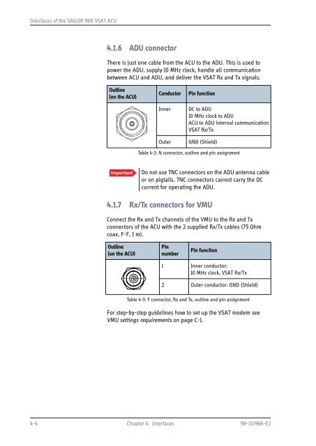
- Page 84 and 85: Interfaces of the SAILOR 900 VSAT A
- Page 86 and 87: Interfaces of the SAILOR 900 VSAT A
- Page 88 and 89: Interfaces of the VMU 4.2.2 Connect
- Page 90 and 91: Interfaces of the VMU 4.2.5 Connect
- Page 92 and 93: Power cable selection 5.2 Power cab
- Page 94 and 95: Connecting power For other cable ty
- Page 96 and 97: Power up 5.4.0.1 Initialisation in
- Page 98 and 99: Introduction to the built-in web in
- Page 100 and 101: Calibration of the SAILOR 900 VSAT
- Page 102 and 103: Calibration of the SAILOR 900 VSAT
- Page 104 and 105: Calibration of the SAILOR 900 VSAT
- Page 106 and 107: Calibration of the SAILOR 900 VSAT
- Page 108 and 109: Calibration of the SAILOR 900 VSAT
- Page 110 and 111: Configuration with the web interfac
- Page 112 and 113: Configuration with the web interfac
- Page 114 and 115: Configuration with the web interfac
- Page 116 and 117: Configuration with the web interfac
- Page 118 and 119: Configuration with the web interfac
- Page 120 and 121: Configuration with the web interfac
- Page 122 and 123: Configuration with the web interfac
- Page 124 and 125: Configuration with the web interfac
- Page 126 and 127: Configuration with the web interfac
- Page 128 and 129: Configuration with the web interfac
- Page 130 and 131: Configuration with the web interfac
- Page 132 and 133:
Configuration with the web interfac
- Page 134 and 135:
Configuration with the web interfac
- Page 136 and 137:
Configuration with the web interfac
- Page 138 and 139:
Configuration with the web interfac
- Page 140 and 141:
Configuration with the web interfac
- Page 142 and 143:
Configuration with the web interfac
- Page 144 and 145:
Configuration with the web interfac
- Page 146 and 147:
Keypad and menus of the ACU After 1
- Page 148 and 149:
Keypad and menus of the ACU 6.4.3.1
- Page 150 and 151:
Keypad and menus of the ACU SATELLI
- Page 152 and 153:
SNMP support 6-56 Chapter 6: Config
- Page 154 and 155:
Installation check list: Antenna St
- Page 156 and 157:
Installation check list: ACU, conne
- Page 158 and 159:
Installation check list: Functional
- Page 160 and 161:
SAILOR 900 VSAT Viewing system para
- Page 162 and 163:
Getting support: Helpdesk 9.1 Getti
- Page 164 and 165:
Getting support: Helpdesk 9.1.1.4 S
- Page 166 and 167:
Software update Note that the uploa
- Page 168 and 169:
Status signalling with LEDs and sta
- Page 170 and 171:
Status signalling with LEDs and sta
- Page 172 and 173:
Removal and replacement of ADU modu
- Page 174 and 175:
Removal and replacement of ADU modu
- Page 176 and 177:
Removal and replacement of ADU modu
- Page 178 and 179:
Removal and replacement of ADU modu
- Page 180 and 181:
Removal and replacement of ADU modu
- Page 182 and 183:
Removal and replacement of ADU modu
- Page 184 and 185:
Removal and replacement of ADU modu
- Page 186 and 187:
Removal and replacement of ADU modu
- Page 188 and 189:
Removal and replacement of ADU modu
- Page 190 and 191:
Removal and replacement of ADU modu
- Page 192 and 193:
Removal and replacement of ADU modu
- Page 194 and 195:
Removal and replacement of ADU modu
- Page 196 and 197:
Removal and replacement of ADU modu
- Page 198 and 199:
Removal and replacement of ADU modu
- Page 200 and 201:
Removal and replacement of ADU modu
- Page 202 and 203:
Removal and replacement of ADU modu
- Page 204 and 205:
Removal and replacement of ADU modu
- Page 206 and 207:
Removal and replacement of ADU modu
- Page 208 and 209:
Removal and replacement of ADU modu
- Page 210 and 211:
Removal and replacement of ADU modu
- Page 212 and 213:
Removal and replacement of ADU modu
- Page 214 and 215:
Removal and replacement of ADU modu
- Page 216 and 217:
Removal and replacement of ADU modu
- Page 218 and 219:
Removal and replacement of ADU modu
- Page 220 and 221:
Removal and replacement of ADU modu
- Page 222 and 223:
Removal and replacement of ADU modu
- Page 224 and 225:
Removal and replacement of ADU modu
- Page 226 and 227:
Removal and replacement of ADU modu
- Page 228 and 229:
Removal and replacement of ADU modu
- Page 230 and 231:
Removal and replacement of ADU modu
- Page 232 and 233:
Removal and replacement of ADU modu
- Page 234 and 235:
Removal and replacement of ADU modu
- Page 236 and 237:
Removal and replacement of ADU modu
- Page 238 and 239:
Removal and replacement of ADU modu
- Page 240 and 241:
Removal and replacement of ADU modu
- Page 242 and 243:
Removal and replacement of ADU modu
- Page 244 and 245:
Removal and replacement of ADU modu
- Page 246 and 247:
Removal and replacement of ADU modu
- Page 248 and 249:
Removal and replacement of ADU modu
- Page 250 and 251:
Updating VIM/PCM calibration data F
- Page 252 and 253:
Troubleshooting 9.7.4 Troubleshooti
- Page 255:
Appendices
- Page 258 and 259:
SAILOR 900 VSAT system components A
- Page 260 and 261:
SAILOR 900 VSAT system components A
- Page 262 and 263:
Outline drawings A.2 Outline drawin
- Page 264 and 265:
Outline drawings A.2.3 ACU, 19 inch
- Page 266 and 267:
VSAT LNB Data Sheet (physical LNB)
- Page 268 and 269:
VSAT 8 W BUC Data Sheet (Extended)
- Page 270 and 271:
Modem Cable Comtech Serial & RSSI T
- Page 272 and 273:
Modem Cable iNIFINITI iDirect VSAT
- Page 274 and 275:
Open AMIP setup for iDirect INFINIT
- Page 276 and 277:
Open AMIP setup for iDirect INFINIT
- Page 278 and 279:
Open AMIP setup for iDirect INFINIT
- Page 280 and 281:
Open AMIP setup for iDirect INFINIT
- Page 282 and 283:
Non-Open-AMIP setup for iDirect iNF
- Page 284 and 285:
Non-Open-AMIP setup for iDirect iNF
- Page 286 and 287:
Comtech 570L, ROSS box & ACU C.3 Co
- Page 288 and 289:
STM SatLink 2900 VSAT modem To disp
- Page 290 and 291:
Gilat SkyEdge II VSAT modem Paramet
- Page 292 and 293:
Introduction D.1.1 Telnet connectio
- Page 294 and 295:
Supported commands D.2 Supported co
- Page 296 and 297:
Supported commands Command help tra
- Page 298 and 299:
Supported commands Command satellit
- Page 300 and 301:
Supported commands Command system r
- Page 302 and 303:
Supported commands D-12 Chapter D:
- Page 304 and 305:
VSAT coverage Satellite name Satell
- Page 306 and 307:
Grounding Recommendations F.2 Groun
- Page 308 and 309:
Grounding Recommendations It is alw
- Page 310 and 311:
Alternative grounding for steel hul
- Page 312 and 313:
Alternative grounding for aluminum
- Page 314 and 315:
Alternative grounding for fibre gla
- Page 316 and 317:
Separate ground cable F.6.2 Ground
- Page 318 and 319:
Jumper cable for grounding F.7 Jump
- Page 320 and 321:
RF interference F-16 Chapter F: Gro
- Page 322 and 323:
List of ADU events G.2 List of ADU
- Page 324 and 325:
List of ADU events Error code (ID)
- Page 326 and 327:
List of ADU events Error code (ID)
- Page 328 and 329:
List of ADU events Error code (ID)
- Page 330 and 331:
List of ACU events Error code (ID)
- Page 332 and 333:
List of ACU events Error code (ID)
- Page 334 and 335:
CE (R&TTE) H-2 Appendix H: Approval
- Page 336 and 337:
Glossary ETSI European Telecommunic
- Page 338 and 339:
Glossary RSSI Received Signal Stren
- Page 340 and 341:
Index browser settings for web inte
- Page 342 and 343:
Index F factory default calibration
- Page 344 and 345:
Index OpenAMIP setup, C-2 supported
- Page 346:
Index symbol rate DVB, azimuth cali


