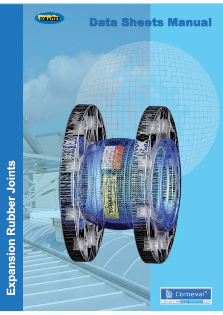
TORAFLEX® RUBBER JOINTS - COMEVAL
TORAFLEX® RUBBER JOINTS - COMEVAL
TORAFLEX® RUBBER JOINTS - COMEVAL
You also want an ePaper? Increase the reach of your titles
YUMPU automatically turns print PDFs into web optimized ePapers that Google loves.
TORAFLEX® <strong>RUBBER</strong> <strong>JOINTS</strong><br />
Index<br />
Data Sheets Manual<br />
General Design Considerations 4<br />
Rubber Bellows - Selection Guide 5<br />
Rubber Bellows - Working Parameters 6<br />
S10 - S15 - S20 - S30 Effective Cross Sectional Area 7<br />
S10 - S15 Single Sphere Type - Attributes of Design 8<br />
S10 - S15 Single Sphere Type - Parts and Materials 9<br />
S10 Single Sphere Type - Joint Dimensions and Permissible Movements 10<br />
S15 Single Sphere Type - Joint Dimensions and Permissible Movements 11<br />
S20 Double Sphere Type - Attributes of Design 12<br />
S20 Double Sphere Type - Parts and Materials 13<br />
S20 Double Sphere Type - Joint Dimensions and Permissible Movements 14<br />
S30 Double Sphere Threaded Type - Attributes of Design 15<br />
S30 Double Sphere Threaded Type - Parts and Materials 16<br />
S30 Double Sphere Threaded Type - Joint Dimensions and Permissible Movements 17<br />
S10 - S15 - S20 Flanges Drilling 18<br />
S10 - S20 - Rubber Bellow Dimensions for Installation purpose 19<br />
Accessories 20<br />
Limit Rods 21<br />
Limit Rods - S10 22<br />
Limit Rods - S20 23<br />
Installation Operating Manual (IOM) 24-30<br />
Data subject to change without prior notice<br />
3
TORAFLEX® <strong>RUBBER</strong> <strong>JOINTS</strong><br />
General Design Considerations<br />
Data Sheets Manual<br />
TORAFLEX® Rubber Joints are devised for piping works, consisting of a flexible<br />
main shell made of synthetic rubber with inner reinforcements to provide consistency,<br />
and pipe connections by means of loose flanges or threaded unions.<br />
Rubber joints are easy to install due to their light weight and relatively small space<br />
requirement and their importance in the industry today is of enormous value as they<br />
protect highly valued installations and equipment and provide many benefits when<br />
installed into any rigid pipe system:<br />
- Noise and vibrations caused by equipment such as pumps are absorbed by Rubber<br />
Joints. Noise is a very uncomfortable element for workers at plants and vibration<br />
causes fatigue stress in pipes and equipment that may easily lead to destruction.<br />
Rubber Joints alleviate such problems.<br />
- Thermal movements appear in any rigid system due to temperature changes. Rubber<br />
Joints balance such movements.<br />
- Rubber Joints provide a great assistance to the plant commissioning team by balancing<br />
slight pipe works misalignments and can even be used as telescopic mounting<br />
kits.<br />
- Rubber joints can withstand surge pressures and mitigate the effects caused by<br />
water hammers thanks to their relatively high tensile strength.<br />
- Thanks to its rubber composition and wide range of material options, they can work<br />
in a vast number of applications.<br />
- An additional advantage is its non-conductive feature, very useful to avoid the electrolysis<br />
problem that appears when putting two different metals in contact.<br />
TORAFLEX® Rubber Joints quality is backed up by experienced chemists and polymer<br />
specialised engineers and strict quality procedures. The whole process commences<br />
when selecting the rubber raw material in form of powder, which is finely<br />
mixed up according to the right engineering formulation, bonding, vulcanisation,<br />
cooling and cure period. Each joint is then subject to an individual and thoughtful<br />
testing procedure, including visual and functional tests to ensure their perfect performance.<br />
Results are registered and the joint is duly identified for full traceability.<br />
TORAFLEX® Rubber Joints are comprehensive of a compact range of standard<br />
products with highly serialized production. Besides, our R+D+I section is ready to<br />
provide customized solutions to meet virtually any requirement.<br />
As a result, we are in disposition to offer a high quality product, at a very competitive<br />
price and with large availability from stock.<br />
Our specialised team, modern facilities, established quality procedures and dedicated<br />
service support provide added value to our products. We are ready to share our<br />
experience of more than 30 years supplying these products.<br />
TORAFLEX® Rubber Joints are widely used in the industry of today. The following<br />
applications can be outlined:<br />
Marine: (Fresh Water Generators, Machine Room Equipment, Marine Engines, On<br />
Deck Systems, Water Cooling Lines, Lubricating circuits...).<br />
H.V.A.C: (Heating, Ventilating and Air Conditioned, specially absorbing vibrations<br />
and noise caused by pulsating pressure stations, cooling towers, condensers, chillers,<br />
compressors, rooters,,,)<br />
Power: (Hydroelectric plants, Turbine lines, cooling towers, condensate lines and<br />
deaireators..)<br />
Water Works and Environmental Services: (Water Treatment plants, Pollution filters,<br />
strength balance in sewage lines, centrifugal rooters, sludge pumping lines....)<br />
Process Industry: (slurries, solvents and other chemical compounds).<br />
Data subject to change without prior notice<br />
4
TORAFLEX® <strong>RUBBER</strong> <strong>JOINTS</strong><br />
Rubber Bellows - Selection Guide<br />
Data Sheets Manual<br />
NBR Butadiene Acrylonitrile (-20ºC) -10ºC ... 75ºC (90ºC)<br />
Lubricating oil, cutting oils, fuel oils, animal and vegetable oils, aviation kerosen, LPG, oily air, natural gas.<br />
Generally resistant to oils and solvents. Not suitable for steam or hot water. Limited resistance to ozone and wheather.<br />
EPDM Ethylene Propylene Diene (-20ºC) -5ºC ... 90ºC (110ºC)<br />
Salts in water, diluted acids, alkaline solutions, ester, ketones, alcohols, glycols, hot water, intermittent steam, sterilisation<br />
Good resistance to ozone and wheather.<br />
It is attacked by hydrocarbon solutions, chlorinated hydrocarbons and other petroleum based oils.<br />
Hypalon (CSM) Chlorosulfonated polyethylene (-20ºC) -10ºC ... 80ºC (90ºC)<br />
Good chlorine and weather resistance. Resistant to diluted acids and bases. Low resistance to oil and fats<br />
Neoprene (CR) Chloroprene rubber (-20ºC) -10ºC ... 75ºC (90ºC)<br />
Good behaviour with water and many oils, and generally with many inorganic and organic products. Nearly tight with hydrocarbon<br />
gases. Good resistance to weather.<br />
Viton (FPM) Vinylidenefluoride-hexafluoro-propyleneco-polymer (-10ºC) -5ºC ... 135ºC (150º)<br />
Strong and weak mineral acids, aliphatic hydrocarbons, chlorine gas, oils, aliphatic acids, phosporic acids, ozone, certain<br />
aromatic solvents. Not suitable for hot water, steam and dry heat. Not suitable for ketones and chlorine.<br />
Butyl (IIR) Isobutene-Isoprene (-20ºC) -10ºC .... 75ºC (90ºC)<br />
Dilute mineral acids and alkalies, gases, compressed air (oil free), acidic slurries, chlorine free hydrochloric acid.<br />
Resistance to concentrated acids is good with some important exceptions as nitric or sulphuric acids.<br />
Good resistance to weather.<br />
Natural Rubber (IR) Polyisoprene (-20ºC) -10ºC .... 70ºC (80ºC)<br />
Inorganic salt solutions, dilute mineral acids, alkalies and salts. Abrasive services.<br />
Not resistant to oxidizing media. Oils and most organic solvents attack it.<br />
PTFE/EPDM Virgin PTFE + EPDM (-20ºC) -5ºC ... 90ºC (110ºC)<br />
Excellent resistance to chemicals or biopharmaceuticals, strong acids and solvents, alkalies and salts in water.<br />
Excellent resistance to weather.<br />
Breaf Peak Temperature<br />
Working Temperature<br />
Temperature ranges given just for reference.<br />
Pressure-temperature rating and material compatibility also to be considered for rubber selection.<br />
Please consult our Technical Department for a particular application.<br />
Data subject to change without prior notice<br />
5
TORAFLEX® <strong>RUBBER</strong> <strong>JOINTS</strong><br />
Rubber Bellows - Working Parameters<br />
Data Sheets Manual<br />
-With PTFE sleeve, maximum working pressure is 7 bar.<br />
-Check also medium-rubber compatibility .<br />
JOINT<br />
S10-S15-S20 DN32-200 (1.1/4”-8”)<br />
S10-S15-S20 DN200-600 (10”-24”)<br />
S30 DN15-80 (1/2”-3”)<br />
BURST PRESSURE<br />
60 bar<br />
40 bar<br />
30 bar<br />
VACUUM APPLICATION<br />
Rubber Joints are resistant to negative pressures to a certain extent. They can become wrinkled depending on vacuum suction degree; herewith the<br />
guidelines for vacuum applications:<br />
JOINT<br />
S10-S15 DN32-200 (1.1/4”-8”)<br />
S10-S15 DN250-600 (10”-24”)<br />
S20 DN32-600 (1.1/4”-24”)<br />
S30 DN15-80 (1/2”-3”)<br />
TEMPORAL VACUUM LIMIT<br />
-0,55 bar-g (0,45 bar-abs)<br />
-0,25 bar-g (0,75 bar-abs)<br />
For temporal vacuum service beyond these limits, or in case of permanent vacuum<br />
service at any value, use special joints with vacuum ring and limit rods assembled as<br />
shown in fi gure at left.<br />
Limits rods for vacuum application<br />
in S10 and S20 Joints<br />
USE OF ROOT RINGS FOR DOUBLE SPHERE <strong>RUBBER</strong> <strong>JOINTS</strong><br />
16 bar<br />
10 bar<br />
S20<br />
USE ROOT RING<br />
NO NEED FOR ROOT RING<br />
USE ROOT RING &<br />
SPECIAL <strong>RUBBER</strong><br />
CONSTRUCTION<br />
16 bar<br />
10 bar<br />
DN32-DN200 DN250-DN300 DN350-DN600<br />
S30<br />
USE ROOT RING<br />
NO NEED FOR ROOT RING<br />
S20 with root ring split type<br />
-10ºC<br />
60ºC<br />
110ºC<br />
S30 with root ring integral type<br />
Data subject to change without prior notice<br />
6
TORAFLEX® <strong>RUBBER</strong> <strong>JOINTS</strong><br />
S10 - S20 - S30 Effective Cross Sectional Area<br />
Data Sheets Manual<br />
REACTION FORCES<br />
Rubber Joints are fl exible components which break the pipe system rigidity. A Rubber Joint acts as a piston by the forces<br />
arising from the internal pressure of the pipe. To prevent the pipes from damage they have to be properly anchored in<br />
order to absorb these reaction forces (Fr).<br />
The reaction force caused by internal pressure in a Rubber Joint is calculated<br />
by the following formula:<br />
Fr (N) = P (kg/cm 2 ) x A (cm 2 ) x 10<br />
Fr =Reaction Force<br />
P = Pressure (Maximum Working Pressure and<br />
Testing Pressure must be considered)<br />
A = Effective cross sectional area<br />
Joint under pressure acts as a piston.<br />
Results shown when working without anchoring.<br />
EFFECTIVE AREA VALUES<br />
In rest position<br />
STYLE S-10 S-20 S-30<br />
SIZE DN Effective Area (cm 2 )<br />
20 - - 7<br />
25 - - 13<br />
32 21 21 17<br />
40 21 21 25<br />
50 42 42 35<br />
65 59 59 49<br />
80 77 85 71<br />
100 129 129 -<br />
125 193 193 -<br />
150 277 277 -<br />
200 437 437 -<br />
250 692 692 -<br />
300 934 934 -<br />
350 1086 1110 -<br />
400 1445 1492 -<br />
450 1847 1839 -<br />
500 2306 2222 -<br />
600 3286 3337 -<br />
After compressed<br />
STYLE S-10 S-20 S-30<br />
SIZE DN Effective Area (cm 2 )<br />
20 - - 20<br />
25 - - 31<br />
32 28 82 37<br />
40 28 82 48<br />
50 52 119 62<br />
65 77 147 80<br />
80 97 186 107<br />
100 167 269 -<br />
125 240 360 -<br />
150 333 471 -<br />
200 535 702 -<br />
250 814 1017 -<br />
300 1075 1307 -<br />
350 1237 1358 -<br />
400 1618 1779 -<br />
450 2042 2155 -<br />
500 2524 2568 -<br />
600 3545 3759 -<br />
Other Reaction Forces:<br />
- Reaction forces caused by the innate joint resistance to move, calculated through the joint stiffness, normally given in<br />
N/mm (linear) and Nm (torsion),<br />
- Reaction forces caused by the friction of the guides.<br />
- Apart from reaction forces caused by the joint installation itself, pipe system weight and centrifugal forces on bends<br />
caused by velocity of the fl uid must also be considered for anchoring.<br />
Data subject to change without prior notice<br />
7
TORAFLEX® <strong>RUBBER</strong> <strong>JOINTS</strong><br />
S10 - S15 Single Sphere Type<br />
Attributes of Design<br />
Data Sheets Manual<br />
8 Light and easy to install,<br />
little installation space required,<br />
easy maintenance<br />
of replaceable bellows.<br />
1 Spherical design for better<br />
strength and effi ciency.<br />
2 Precision injection moulded<br />
of synthetic rubber and nylon.<br />
7 - 4 different allowable<br />
movements: axial compression<br />
and expansion,<br />
lateral and angular defl<br />
ection.<br />
3 Outer layer protects the<br />
bellows surface form eventual<br />
ozone attack, strikes<br />
and other environmental aggressions.<br />
6 Loose fl anges for easy assembly,<br />
specially machined to accept the<br />
full turned rubber, with standard<br />
execution in zinc plated steel.<br />
5 Full turned rubber design,<br />
self-sealing, no additional gaskets<br />
are required; it prevents<br />
electrolytic corrosion.<br />
4 Rugged design with high<br />
burst pressure, to absorb<br />
noise and vibration and withstand<br />
water hammers to a<br />
certain extent by:<br />
- Inner Reinforcement placed<br />
in between the outer and inner<br />
layers. Made of Nylon plaited<br />
fabrics as standard, which<br />
provide high shell moulding<br />
resistance.<br />
-End Bellows Reinforcement.<br />
Hardened steel wires to provide<br />
a greater consistence to<br />
the bellows outer neck.<br />
9 Lot number punched for<br />
full traceability purpose.<br />
10 Rubber material identifi cation<br />
and maximum service temperature.<br />
Data subject to change without prior notice<br />
8
TORAFLEX® <strong>RUBBER</strong> <strong>JOINTS</strong><br />
S10 and S15 Single Sphere Type<br />
Parts and Materials<br />
Data Sheets Manual<br />
1- Vulcanised Rubber Bellow: 1.1 Rubber core (inner)<br />
1.2 Nylon tire cord<br />
1.3 Rubber cover (outer)<br />
1.4 Hard Steel Wire<br />
Rubber options: EPDM, NBR, Hypalon, Neoprene, Viton, Butyl Rubber,<br />
Natural Rubber, PTFE/EPDM<br />
2- Loose Flanges:<br />
Standard Material: Carbon Steel Zinc Plated S235JR to EN10025<br />
(old St 37-2 to DIN 17100)<br />
Flange Options: Stainless Steel AISI 304, AISI 316, etc.<br />
Data subject to change without prior notice<br />
9
TORAFLEX® <strong>RUBBER</strong> <strong>JOINTS</strong><br />
S10 Single Sphere Type<br />
Joint Dimensions and Permissible Movements<br />
Data Sheets Manual<br />
Permissible Movements<br />
Initial Position<br />
Axial Compression Axial Expansion Lateral Deflection Angular Defl ection<br />
DN<br />
Inch mm INITIAL<br />
(L)<br />
BUILDING LENGTH<br />
(mm)<br />
TOLERANCE<br />
INSTALLED<br />
(min-max)<br />
MAX. MOVEMENTS ALLOWED FROM INITIAL POSITION*<br />
AXIAL<br />
COMPRESSION<br />
(mm)<br />
AXIAL<br />
EXPANSION<br />
(mm)<br />
LATERAL<br />
DEFLECTION<br />
(mm)<br />
ANGULAR<br />
DEFLECTION<br />
Dimensions are expressed in mm, and subjected to manufacturing tolerances. Data can be altered without notice by our Design Department for the product benefi t.<br />
ФA<br />
(mm)<br />
ФC<br />
(mm)<br />
Approx.<br />
Weight (kg)<br />
PN10<br />
PN16/<br />
ASA150<br />
1.1/4” 32 95 89-97 8 4 8 15º 68 35 3,2 3,2<br />
1.1/2” 40 95 89-97 8 5 8 15º 68 37 4 4<br />
2” 50 105 99-107 8 6 8 15º 86 50 5 5<br />
2.1/2” 65 115 107-118 12 6 10 15º 106 65 6 6<br />
3” 80 130 122-133 12 10 10 15º 118 72 8 8<br />
4” 100 135 122-140 18 10 12 15º 152 98 9 9<br />
5” 125 170 156-175 18 10 12 15º 182 122 11 11<br />
6” 150 180 167-185 18 10 12 15º 213 146 13 13<br />
8” 200 205 186-212 25 14 22 15º 262 194 19 19<br />
10” 250 240 221-247 25 14 22 15º 323 245 24 27<br />
12” 300 260 241-267 25 14 22 15º 372 295 29 33<br />
14” 350 265 246-273 25 14 22 15º 409 320 39 48<br />
16” 400 265 246-273 25 14 22 15º 471 365 48 62<br />
18” 450 265 246-273 25 14 22 15º 520 420 56 73<br />
20” 500 265 246-273 25 14 22 15º 572 480 69 111<br />
24” 600 265 246-273 25 14 22 15º 690 585 71 138<br />
* The stated movements are solely valid with the joint subject to a single movement direction. Values are proportionally reduced along with the movement combination.<br />
* Given tolerance installed and movements allowed are valid for rubber bellows. For bellows with PTFE sleeve, values must be reduced by 1/2.<br />
* Increasing temperatures reduce the permissible movements capacity and number of cycles.<br />
Manufacture Design Standards<br />
- QA certifi ed to EN ISO 9001 procedures.<br />
- Testing procedure according to EN12266-1.<br />
- Marking according to EN19.<br />
- Flanges drilled to EN1092-1 PN10, PN16, or ASME B16.5 ASA150.<br />
- Rubber Joints are excluded from the Pressure Equipment Directive PED 97/23/CE, according to its article 1.3-15.<br />
Data subject to change without prior notice<br />
10
TORAFLEX® <strong>RUBBER</strong> <strong>JOINTS</strong><br />
S15 Single Sphere Type - Single Length<br />
Joint Dimensions and Permissible Movements<br />
Data Sheets Manual<br />
Permissible Movements<br />
Initial Position<br />
Axial Compression Axial Expansion Lateral Deflection Angular Defl ection<br />
DN<br />
Inch mm INITIAL<br />
(L)<br />
BUILDING LENGTH<br />
(mm)<br />
TOLERANCE<br />
INSTALLED<br />
(min-max)<br />
MAX. MOVEMENTS ALLOWED FROM INITIAL POSITION*<br />
AXIAL<br />
COMPRESSION<br />
(mm)<br />
AXIAL<br />
EXPANSION<br />
(mm)<br />
LATERAL<br />
DEFLECTION<br />
(mm)<br />
ANGULAR<br />
DEFLECTION<br />
Dimensions are expressed in mm, and subjected to manufacturing tolerances. Data can be altered without notice by our Design Department for the product benefi t.<br />
ФA<br />
(mm)<br />
ФC<br />
(mm)<br />
Approx.<br />
Weight (kg)<br />
1” 25 130 122-133 30 20 30 35º 60 25 4 4<br />
1.1/4” 32 130 122-133 30 20 30 35º 68 35 4 4<br />
1.1/2” 40 130 122-133 30 20 30 35º 68 37 4,5 4,5<br />
2” 50 130 122-133 30 20 30 35º 86 50 5,5 5,5<br />
2.1/2” 65 130 122-133 30 20 30 30º 106 65 7 7<br />
3” 80 130 122-133 30 20 30 30º 118 72 8 8<br />
4” 100 130 122-133 30 20 30 25º 152 98 9 9<br />
5” 125 130 122-133 30 20 30 25º 182 122 11 11<br />
6” 150 130 122-133 30 20 30 15º 213 146 13 13<br />
8” 200 130 122-133 30 20 30 15º 262 194 19 19<br />
10” 250 130 122-133 30 20 30 10º 323 245 24 27<br />
12” 300 130 122-133 30 20 30 10º 372 295 29 33<br />
PN10<br />
PN16/<br />
ASA150<br />
* The stated movements are solely valid with the joint subject to a single movement direction. Values are proportionally reduced along with the movement combination.<br />
* Given tolerance installed and movements allowed are valid for rubber bellows. For bellows with PTFE sleeve, values must be reduced by 1/2.<br />
* Increasing temperatures reduce the permissible movements capacity and number of cycles.<br />
Manufacture Design Standards<br />
- QA certifi ed to EN ISO 9001 procedures.<br />
- Testing procedure according to EN12266-1.<br />
- Marking according to EN19.<br />
- Flanges drilled to EN1092-1 PN10, PN16, or ASME B16.5 ASA150.<br />
- Rubber Joints are excluded from the Pressure Equipment Directive PED 97/23/CE, according to its article 1.3-15.<br />
Data subject to change without prior notice<br />
11
TORAFLEX® <strong>RUBBER</strong> <strong>JOINTS</strong><br />
S20 Double Sphere Type<br />
Attributes of Design<br />
Data Sheets Manual<br />
8 Light and easy to install,<br />
little installation space required,<br />
easy maintenance<br />
of replaceable bellows.<br />
1 Double sphere design allow greater<br />
axial, lateral and angular movements<br />
subject to less effort and material wearing<br />
down during movements.<br />
2 Precision injection moulded<br />
of synthetic rubber and nylon.<br />
7 - 4 different allowable<br />
movements: axial compression<br />
and expansion,<br />
lateral and angular defl<br />
ection.<br />
3 Outer layer protects the<br />
bellows surface from eventual<br />
ozone attack, strikes<br />
and other environmental aggressions.<br />
6 Loose fl anges for easy<br />
assembly, specially machined<br />
to accept the full turned<br />
rubber, with standard execution<br />
in zinc plated steel.<br />
5 Full turned rubber design,<br />
self-sealing, no additional<br />
gaskets are required prevents<br />
electrolytic corrosion.<br />
4 Rugged design with high<br />
burst pressure, to absorb<br />
noise and vibration and withstand<br />
water hammers to a<br />
certain extent by:<br />
-Inner Reinforcement placed<br />
in between the outer and inner<br />
layers. Made of Nylon plaited<br />
fabrics as standard, which<br />
provide high shell moulding<br />
resistance.<br />
-End Bellows Reinforcement.<br />
Hardened steel wires to provide<br />
a greater consistence to<br />
the bellows outer neck.<br />
9 Lot number punched for<br />
full traceability purpose.<br />
10 Rubber material identifi cation<br />
and maximum service temperature.<br />
Data subject to change without prior notice<br />
12
TORAFLEX® <strong>RUBBER</strong> <strong>JOINTS</strong><br />
S20 Double Sphere Type<br />
Parts and Materials<br />
Data Sheets Manual<br />
1- Vulcanised Rubber Bellow: 1.1 Rubber core (inner)<br />
1.2 Nylon tire cord<br />
1.3 Rubber cover (outer)<br />
1.4 Hard Steel Wire<br />
Rubber options: EPDM, NBR, Hypalon, Neoprene, Viton, Butyl Rubber,<br />
Natural Rubber, PTFE/EPDM<br />
2- Loose Flanges:<br />
Standard Material: Carbon Steel Zinc Plated S235JR to EN10025<br />
(old St 37-2 to DIN 17100)<br />
Flange Options: Stainless Steel AISI 304, AISI 316, etc.<br />
Data subject to change without prior notice<br />
13
TORAFLEX® <strong>RUBBER</strong> <strong>JOINTS</strong><br />
S20 Double Sphere Type<br />
Joint Dimensions and Permissible Movements<br />
Data Sheets Manual<br />
Permissible Movements<br />
Initial Position<br />
Axial Compression Axial Expansion Lateral Deflection Angular Defl ection<br />
DN<br />
Inch mm INITIAL<br />
(L)<br />
BUILDING LENGTH<br />
(mm)<br />
TOLERANCE<br />
INSTALLED<br />
(min-max)<br />
MAX. PERMISSIBLE MOVEMENTS FROM INITIAL POSITION*<br />
AXIAL<br />
COMPRESSION<br />
(mm)<br />
AXIAL<br />
EXPANSION<br />
(mm)<br />
LATERAL<br />
DEFLECTION<br />
(mm)<br />
ANGULAR<br />
DEFLECTION<br />
1.1/4” 32 175 168-178 50 30 35 40º 68 35 3,5 3,5<br />
1.1/2” 40 175 168-178 50 30 35 40º 68 37 4 4<br />
2” 50 175 168-178 50 30 35 40º 86 50 5,5 5,5<br />
2.1/2” 65 175 168-178 50 30 35 40º 106 65 6 6<br />
3” 80 175 168-178 50 30 35 40º 118 77 8 8<br />
4” 100 225 218-228 57 35 40 35º 152 98 9 9<br />
5” 125 225 218-228 57 35 40 35º 182 122 12 12<br />
6” 150 225 218-228 57 35 40 35º 213 146 14 14<br />
8” 200 325 318-328 63 35 45 30º 262 194 20 21<br />
10” 250 325 318-328 63 35 45 30º 323 245 26 29<br />
12” 300 325 318-328 63 35 45 30º 372 295 32 35<br />
14” 350 350 344-353 40 30 30 20º 410 330 42 50<br />
16” 400 350 344-353 40 30 30 20º 473 380 54 67<br />
18” 450 350 344-353 40 30 30 20º 522 428 62 77<br />
20” 500 350 344-353 40 30 30 20º 570 476 77 119<br />
24” 600 350 344-353 40 30 30 20º 690 596 82 147<br />
Dimensions are expressed in mm, and subjected to manufacturing tolerances. Data can be altered without notice by our Design Department for the product benefi t.<br />
* The stated movements are solely valid with the joint subject to a single movement direction. Values are proportionally reduced along with the movement combination.<br />
* Increasing temperatures reduce the permissible movements capacity and number of cycles.<br />
ФA<br />
(mm)<br />
ФC<br />
(mm)<br />
Approx.<br />
Weight (kg)<br />
PN10<br />
PN16/<br />
ASA150<br />
Manufacture Design Standards<br />
- QA certifi ed to EN ISO 9001 procedures.<br />
- Testing procedure according to EN12266-1.<br />
- Marking according to EN19.<br />
- Flanges drilled to EN1092-1 PN10, PN16, or ASME B16.5 ASA150.<br />
- Rubber Joints are excluded from the Pressure Equipment Directive PED 97/23/CE, according to its article 1.3-15.<br />
Data subject to change without prior notice<br />
14
TORAFLEX® <strong>RUBBER</strong> <strong>JOINTS</strong><br />
S30 Double Sphere Threaded Type<br />
Attributes of Design<br />
Data Sheets Manual<br />
1 Double Sphere design for better strength<br />
and effi ciency allow greater axial, lateral and<br />
angular movements subject to less effort and<br />
material wearing down during movements.<br />
2 Precision injection moulded<br />
of synthetic rubber inserted into<br />
union threads .<br />
3 Outer layer protects<br />
the bellows surface form<br />
eventual ozone attack,<br />
strikes and other environmental<br />
aggressions.<br />
5 Light and easy to install, little<br />
installation space required, easy<br />
maintenance of replaceable bellows,<br />
no need for counterfl anges.<br />
4 Rugged design with high burst pressure,<br />
to absorb noise and vibration and withstand<br />
water hammers to a certain extent.<br />
6 Lot number punched for<br />
full traceability purpose.<br />
7 Rubber material identifi cation and<br />
maximum service temperature.<br />
Data subject to change without prior notice<br />
15
TORAFLEX® <strong>RUBBER</strong> <strong>JOINTS</strong><br />
S30 Double Sphere Threaded Type<br />
Parts and Materials<br />
Data Sheets Manual<br />
1- Vulcanised Rubber Bellow: 1.1 Rubber core (inner)<br />
1.2 Nylon tire cord<br />
1.3 Rubber cover (outer)<br />
Rubber options: EPDM, NBR, Hypalon, Neoprene, Viton, Natural Rubber, Butyl Rubber<br />
2- Unions with threaded ends:<br />
Standard Material: Malleable Iron Zinc Plated EN-GJMB-350-10 according to EN1562<br />
(old GTS 35-10 according to DIN 1692)<br />
Data subject to change without prior notice<br />
16
TORAFLEX® <strong>RUBBER</strong> <strong>JOINTS</strong><br />
S30 Double Sphere Threaded Type<br />
Joint Dimensions and Permissible Movements<br />
Data Sheets Manual<br />
Permissible Movements<br />
Initial Position<br />
Axial Compression Axial Expansion Lateral Defl ection Angular Defl ection<br />
Inch<br />
DN BUILDING LENGTH (mm) MAX. PERMISSIBLE MOVEMENTS FROM INITIAL POSITION*<br />
mm<br />
INITIAL<br />
(L)<br />
TOLERANCE<br />
INSTALLED<br />
(min-max)<br />
AXIAL<br />
COMPRESSION<br />
(mm)<br />
AXIAL<br />
EXPANSION<br />
(mm)<br />
LATERAL<br />
DEFLECTION<br />
(mm)<br />
ANGULAR<br />
DEFLECTION<br />
¾” 20 200 194-203 22 6 22 45º 17 0,7<br />
1” 25 200 194-203 22 6 22 45º 25 1,2<br />
1.1/4” 32 200 194-203 22 6 22 45º 32 1,4<br />
1.1/2” 40 200 194-203 22 6 22 45º 39 2<br />
2” 50 200 194-203 22 6 22 45º 47 2,6<br />
2.1/2” 65 240 234-243 22 6 22 45º 60 3,8<br />
3” 80 240 234-243 22 6 22 45º 70 5,2<br />
Dimensions are expressed in mm, and subjected to manufacturing tolerances. Data can be altered without notice by our Design Department for the product benefi t.<br />
ФC<br />
(mm)<br />
Approx.<br />
Weight<br />
(kg)<br />
* The stated movements are solely valid with the joint subject to a single movement direction. Values are proportionally reduced along with the movement combination.<br />
* Increasing temperatures reduce the permissible movements capacity and number of cycles.<br />
Manufacture Design Standards<br />
- QA certifi ed to EN ISO 9001 procedures.<br />
- Testing procedure according to EN12266-1.<br />
- Marking according to EN19.<br />
- Threaded unions to EN 10266-1 (ISO 7-1, DIN2999-1, BS21), with parallel female threads (Gas - Rp - BSPP)<br />
- Rubber Joints are excluded from the Pressure Equipment Directive PED 97/23/CE, according to its article 1.3-15.<br />
Data subject to change without prior notice<br />
17
TORAFLEX® <strong>RUBBER</strong> <strong>JOINTS</strong><br />
S10 - S15 - S20 Flanges Drilling<br />
Data Sheets Manual<br />
n=4 n=8 n=12 n=16 n=20<br />
DN<br />
PN10<br />
Inch mm ØD ØK n Ød<br />
1.1/4” 32 140 100 4 18<br />
1.1/2” 40 150 110 4 18<br />
2” 50 165 125 4 18<br />
2.1/2” 65 185 145 4 18<br />
3” 80 200 160 8 18<br />
4” 100 220 180 8 18<br />
5” 125 250 210 8 18<br />
6” 150 285 240 8 22<br />
8” 200 340 295 8 22<br />
10” 250 395 350 12 22<br />
12” 300 445 400 12 22<br />
14” 350 505 460 16 22<br />
16” 400 565 515 16 26<br />
18” 450 615 565 20 26<br />
20” 500 670 620 20 26<br />
24” 600 780 725 20 30<br />
DN<br />
ANSI150<br />
Inch mm ØD ØK n Ød<br />
1.1/4” 32 118 89 4 16<br />
1.1/2” 40 127 98 4 16<br />
2” 50 153 121 4 19<br />
2.1/2” 65 178 140 4 19<br />
3” 80 191 152 4 19<br />
4” 100 229 191 8 19<br />
5” 125 254 216 8 22<br />
6” 150 279 241 8 22<br />
8” 200 343 298 8 22<br />
10” 250 406 362 12 25<br />
12” 300 483 432 12 25<br />
14” 350 533 476 12 29<br />
16” 400 597 540 16 29<br />
18” 450 635 578 16 32<br />
20” 500 699 635 20 32<br />
24” 600 813 749 20 32<br />
DN<br />
PN16<br />
Inch mm ØD ØK n Ød<br />
1.1/4” 32 140 100 4 18<br />
1.1/2” 40 150 110 4 18<br />
2” 50 165 125 4 18<br />
2.1/2” 65 185 145 4 18<br />
3” 80 200 160 8 18<br />
4” 100 220 180 8 18<br />
5” 125 250 210 8 18<br />
6” 150 285 240 8 22<br />
8” 200 340 295 12 22<br />
10” 250 405 355 12 26<br />
12” 300 460 410 12 26<br />
14” 350 520 470 16 26<br />
16” 400 580 525 16 30<br />
18” 450 640 585 20 30<br />
20” 500 715 650 20 33<br />
24” 600 840 770 20 36<br />
Dimensions are expressed in mm, and subject to manufacturing tolerances.<br />
Data subject to change without prior notice<br />
18
TORAFLEX® <strong>RUBBER</strong> <strong>JOINTS</strong><br />
S10 - S20 - Rubber Bellow Dimensions for Installation purpose<br />
Data Sheets Manual<br />
S10<br />
Size<br />
inch DN ФA ФB ФC ФE ФF e<br />
1 25 60 38 25 54 42 1<br />
1-1/4 32 68 52 37 62 52 2<br />
1-1/2 40 68 52 37 62 52 2<br />
2 50 86 62 50 80 66 2<br />
2-1/2 65 106 83 65 100 86 2<br />
3 80 118 90 72 112 98 2<br />
4 100 152 119 98 145 129 2<br />
5 125 182 144 122 175 157 2<br />
6 150 213 168 146 206 188 2<br />
8 200 262 218 194 252 232 2<br />
10 250 323 269 245 310 290 2<br />
12 300 372 320 295 360 340 2<br />
14 350 409 356 320 400 380 2<br />
16 400 471 406 365 455 435 2<br />
18 450 520 455 420 506 486 2<br />
20 500 572 508 480 555 535 2<br />
24 600 690 626 585 672 650 2<br />
Dimensions in mm., subject to manufacturing tolerances<br />
Size<br />
inch DN ФA ФB ФC ФE ФF e<br />
1 25 55 35 22 50 40 2<br />
1-1/4 32 68 52 37 62 52 2<br />
1-1/2 40 68 52 37 62 52 2<br />
2 50 86 62 50 80 66 2<br />
2-1/2 65 106 83 65 100 86 2<br />
3 80 118 90 77 112 98 2<br />
4 100 152 119 98 145 129 2<br />
5 125 182 144 122 175 157 2<br />
6 150 213 168 146 206 188 2<br />
8 200 262 218 194 252 232 2<br />
10 250 323 269 245 310 290 2<br />
12 300 372 320 295 360 340 2<br />
14 350 410 358 330 400 380 2<br />
16 400 473 412 380 455 435 2<br />
18 450 522 460 428 500 480 2<br />
S20<br />
Dimensions in mm., subject to manufacturing tolerances<br />
Data subject to change without prior notice<br />
19
TORAFLEX® <strong>RUBBER</strong> <strong>JOINTS</strong><br />
Accessories<br />
Data Sheets Manual<br />
Limit Rods for Rubber Joints for S10 - S20<br />
Root Rings Split Type for S20<br />
Root Rings Integral Type for S30<br />
Special Reinforced Rubber Joint for vacuum service<br />
Data subject to change without prior notice<br />
20
TORAFLEX® <strong>RUBBER</strong> <strong>JOINTS</strong><br />
Limit Rods<br />
Data Sheets Manual<br />
The main purpose of Limit Rods is to absorb the force caused by internal pressure, and avoid reaction force over Fix Points. Fix<br />
Points will be released but they are still necessary. A Joint with limit rods will work only with axial movements. They are normally used<br />
with high pressures and large DNs, that may require very strong anchoring. They also relieve pump frames.<br />
Limit rods can control Joint bellow over-extension and/or over-compression.<br />
Limit rods can be used to avoid or correct mounting mistakes by over expansion.<br />
Limit rods can be used for vacuum service in combination with vacuum rings.<br />
Limit Rods Parts:<br />
1 Rod<br />
2 Plate<br />
3 Rubber Gasket<br />
4 Washer<br />
5 Nut<br />
Standard Material: Carbon Steel Zinc Plated S235JR to EN10025<br />
(old St 37-2 to DIN 17100)<br />
Material Options: Stainless Steel AISI 304, AISI 316, etc.<br />
Each Rod Set is comprehensive of:<br />
1 rod + 2 plates + 2 rubber gaskets + 2 washers + 4 nuts<br />
Data subject to change without prior notice<br />
21
TORAFLEX® <strong>RUBBER</strong> <strong>JOINTS</strong><br />
Limit Rods - S10<br />
Data Sheets Manual<br />
Plate<br />
Rod<br />
Rod Sets - S10 PN10<br />
Size<br />
Number of Rod Sets<br />
inch mm. M L A B W° ØD ØE R1 R2 F C T<br />
per Joint<br />
1-1/2” 40 16 240 37 55 90 18 18 18 20 78 60 10 2<br />
2” 50 16 250 45 62,5 90 18 18 18 20 88 65 10 2<br />
2-1/2” 65 16 260 33 72,5 90 18 18 20 20 103 65 10 2<br />
3” 80 16 280 60 80 45 18 18 20 20 61 50 10 2<br />
4” 100 16 290 70 90 45 18 18 20 20 69 50 10 2<br />
5” 125 16 325 85 105 45 18 18 20 20 80 55 10 2<br />
6” 150 16 340 94 120 45 23 18 22 20 92 60 12 2<br />
8” 200 20 370 125 147,5 45 23 23 22 24 113 65 12 2<br />
10” 250 20 440 153 175 30 23 23 22 24 91 65 18 3<br />
12” 300 20 460 178 200 30 23 23 22 24 104 65 18 3<br />
14” 350 20 460 208 230 22,5 23 23 22 24 90 60 20 4<br />
16” 400 20 470 233 257,5 22,5 27 23 25 24 100 60 20 4<br />
18” 450 20 480 258 282,5 18 27 23 25 24 88 60 20 4<br />
20” 500 20 480 285 310 18 27 23 25 24 97 60 20 4<br />
24” 600 24 495 333 362,5 18 30 27 30 28 113 70 20 4<br />
Rod Sets - S10 PN16<br />
Size<br />
Number of Rod Sets<br />
inch mm. M L A B W° ØD ØE R1 R2 F C T<br />
per Joint<br />
1-1/2” 40 16 240 37 55 90 18 18 18 20 78 60 10 2<br />
2” 50 16 250 45 62,5 90 18 18 18 20 88 65 10 2<br />
2-1/2” 65 16 260 53 72,5 90 18 18 20 20 103 65 10 2<br />
3” 80 16 280 60 80 45 18 18 20 20 61 50 10 2<br />
4” 100 16 290 70 90 45 18 18 20 20 69 50 10 2<br />
5” 125 16 325 85 105 45 18 18 20 20 80 55 10 2<br />
6” 150 16 340 98 120 45 23 18 22 20 92 60 12 2<br />
8” 200 20 370 125 147,5 30 23 23 22 24 76 65 12 3<br />
10” 250 20 440 153 177,5 30 27 23 25 24 92 65 18 3<br />
12” 300 20 460 180 205 30 27 23 25 24 106 65 18 3<br />
14” 350 20 460 210 235 22,5 27 23 25 24 92 65 20 4<br />
16” 400 20 470 233 262,5 22,5 30 23 30 24 102 65 20 4<br />
18” 450 20 480 263 292,5 18 30 23 30 24 92 65 20 4<br />
20” 500 20 480 292 325 18 33 23 33 24 102 70 20 4<br />
24” 600 24 495 348 385 18 37 27 37 28 120 80 22 4<br />
Dimensions in mm., subject to manufacturing tolerances<br />
Data subject to change without prior notice<br />
22
TORAFLEX® <strong>RUBBER</strong> <strong>JOINTS</strong><br />
Limit Rods - S20<br />
Data Sheets Manual<br />
Plate<br />
Rod<br />
Rod Sets - S20 PN10<br />
Size<br />
Number of Rod Sets<br />
inch mm. M L A B W° ØD ØE R1 R2 F C T<br />
per Joint<br />
1-1/2” 40 16 320 37 55 90 18 18 18 20 78 60 10 2<br />
2” 50 16 320 45 62,5 90 18 18 18 20 88 65 10 2<br />
2-1/2” 65 16 320 33 72,5 90 18 18 20 20 103 65 10 2<br />
3” 80 16 320 60 80 45 18 18 20 20 61 50 10 2<br />
4” 100 16 380 70 90 45 18 18 20 20 69 50 10 2<br />
5” 125 16 380 85 105 45 18 18 20 20 80 55 10 2<br />
6” 150 16 380 94 120 45 23 18 22 20 92 60 12 2<br />
8” 200 20 515 125 147,5 45 23 23 22 24 113 65 12 2<br />
10” 250 20 515 153 175 30 23 23 22 24 91 65 18 3<br />
12” 300 20 515 178 200 30 23 23 22 24 104 65 18 3<br />
14” 350 20 515 208 230 22,5 23 23 22 24 90 60 20 4<br />
16” 400 20 560 233 257,5 22,5 27 23 25 24 100 60 20 4<br />
18” 450 20 560 258 282,5 18 27 23 25 24 88 60 20 4<br />
20” 500 20 560 285 310 18 27 23 25 24 97 60 20 4<br />
24” 600 24 600 333 362,5 18 30 27 30 28 113 70 20 4<br />
Rod Sets - S20 PN16<br />
Size<br />
Number of Rod Sets<br />
inch mm. M L A B W° ØD ØE R1 R2 F C T<br />
per Joint<br />
1-1/2” 40 16 320 37 55 90 18 18 18 20 78 60 10 2<br />
2” 50 16 320 45 62,5 90 18 18 18 20 88 65 10 2<br />
2-1/2” 65 16 320 53 72,5 90 18 18 20 20 103 65 10 2<br />
3” 80 16 320 60 80 45 18 18 20 20 61 50 10 2<br />
4” 100 16 380 70 90 45 18 18 20 20 69 50 10 2<br />
5” 125 16 380 85 105 45 18 18 20 20 80 55 10 2<br />
6” 150 16 380 98 120 45 23 18 22 20 92 60 12 2<br />
8” 200 20 515 125 147,5 30 23 23 22 24 76 65 12 3<br />
10” 250 20 515 153 177,5 30 27 23 25 24 92 65 18 3<br />
12” 300 20 515 180 205 30 27 23 25 24 106 65 18 3<br />
14” 350 20 515 210 235 22,5 27 23 25 24 92 65 20 4<br />
16” 400 20 560 233 262,5 22,5 30 23 30 24 102 65 20 4<br />
18” 450 20 560 263 292,5 18 30 23 30 24 92 65 20 4<br />
20” 500 20 560 292 325 18 33 23 33 24 102 70 20 4<br />
24” 600 24 600 348 385 18 37 27 37 28 120 80 22 4<br />
Dimensions in mm., subject to manufacturing tolerances<br />
Data subject to change without prior notice<br />
23
TORAFLEX® <strong>RUBBER</strong> <strong>JOINTS</strong><br />
IOM<br />
PRESERVATION, STORAGE & TRANSPORTATION<br />
Data Sheets Manual<br />
- Keep storage protection until installation into the pipe. Always use correct handling means and proper packing for transportation.<br />
- Avoid extreme temperatures, high environmental humidity or corrosive environment. Keep the joints away from sunlight, dust, fl a-<br />
mes or rain to avoid damage and rust of the equipment surface.<br />
- Protect the equipment from sharp objects that could easily damage the rubber faces.<br />
- Avoid bumping or external vibrations. Do not pile up excessive weight. In case of severe bumping inspect the material for any damage<br />
and replace if necessary.<br />
INSTALLATION<br />
Bear in mind the following guidelines along with general installation practice:<br />
Outdoor installation reduces the Joints life span. Rubber bellows are affected by weather conditions (sunlight, ozone, etc.).<br />
In Double Sphere Joints (i.e. S20 and S30 types), use of root rings might be necessary with big sizes, hot water and / or working<br />
pressures above 10 bar. Please check our Data Sheets or consult us in case of doubt.<br />
Avoid high velocities (limits depending on fl uids). As a general guideline, velocity should be less than 3-4 m/s and much lower in case<br />
of abrassive liquids.<br />
Allow enough space to ease maintenance operations.<br />
Do not paint or lubricate Rubber Joints.<br />
Consider the interaction between the system and the equipment. Proper selection and location of the joints, as well as proper guiding<br />
and anchoring of the system are essential for the safe and proper use of the joint, as explained in detail here below.<br />
ATEX: Warning! Elastomeric or fl uoropolymer surfaces should be cleaned if necessary with a wet cloth to avoid electrostatic charge.<br />
Also consider the risk of electrostatic charges created by the fl ow.<br />
A Rubber Joint should work either as an anti-vibration device or as expansion joint, but not both functions at the same time; installation,<br />
pipe anchoring and guiding requirements are different.<br />
Reaction forces. Anchoring and Guiding. Limit rods<br />
REACTION FORCES<br />
Rubber Joints are fl exible components which break the pipe system rigidity. A Rubber Joint acts as a piston by the forces arising<br />
from the internal pressure of the pipe. To prevent the pipes from damage they have to be properly anchored in order to absorb these<br />
reaction forces (Fr).<br />
The reaction force caused by internal pressure in a Rubber Joint iscalculated by the following formula:<br />
Fr (N) = P (kg/cm 2 ) x A (cm 2 ) x 10<br />
Fr =Reaction Force<br />
P = Pressure (Maximum Working Pressure and Testing Pressure must be considered)<br />
A = Effective cross sectional area<br />
Effective area for each Joint type is given in our Data Sheets.<br />
Other Reaction Forces:<br />
Joint under pressure acts as a piston.<br />
Results shown when working without anchoring.<br />
- Reaction forces caused by the innate joint resistance to move, calculated through the Joint stiffness, normally given in N/mm (linear)<br />
and Nm (torsion),<br />
- Reaction forces caused by the friction of the guides..<br />
- Apart from reaction forces caused by the joint installation itself, pipe system weight and centrifugal forces on bends caused by velocity<br />
of the fl uid must also be considered for anchoring.<br />
Data subject to change without prior notice<br />
24
TORAFLEX® <strong>RUBBER</strong> <strong>JOINTS</strong><br />
IOM<br />
Data Sheets Manual<br />
ANCHORING. FIX POINTS<br />
We call Fix Points to the anchors that absorb reaction forces.<br />
Every Rubber Joint has to be installed between two Fix Points.<br />
Fixed point welded for pipes in parallel<br />
Fixed point for elbow<br />
Intermediate Fix Points are the ones just absorbing forces caused by joint stiffness and friction of guides, whereas Main Fix Points<br />
also absorb the forces caused by internal pressure, centrifugal forces and weights not supported by Guides..<br />
Main Fix Points are normally located in pump groups, valves, bends, crosses, line ending or fl ow change sections of the pipe work.<br />
GUIDING<br />
Guides not only support the pipe system weight, but also maintain correct alignment<br />
so that the Joints work adequately. It is important to notice that guides supporting<br />
the pipe system are not fi xed points.<br />
The Guides should be positioned according to certain rules given further on and they<br />
prevent buckling of the line.<br />
Special Guides can be used to allow movement in more than one direction.<br />
Guide with roller stand<br />
LIMIT RODS<br />
The main purpose of Limit Rods is to absorb the force caused by internal pressure, and avoid reaction force over Fix Points. Fix<br />
Points will be released but they are still necessary. A Joint with limit rods will work only with axial movements. They are normally used<br />
with high pressures and large DNs, that may require very strong anchoring. They also relieve pump frames.<br />
Limit rods can control Joint bellow over-extension and/or over-compression.<br />
Limit rods can be used to avoid or correct mounting mistakes by over expansion.<br />
Limit rods can be used for vacuum service in combination with vacuum rings.<br />
Herewith some recommendations for setting fi x anchoring points, guides and limit rods.<br />
Installation Guidelines for Rubber Joints absorbing vibration and noise<br />
Rubber Joints are commonly installed in pump groups to absorb vibration and<br />
noise.<br />
The Rubber Joint must be installed near the pump group, leaving just 1-1,5 DN<br />
distance. Leave more distance in case of abrassive media.<br />
The Pump group frame must be properly anchored to absorb the reaction forces<br />
and another fi x point must be set immediately after the rubber joint to limit the<br />
vibrations amplitude onto the pipe.<br />
Proper guiding of the pipe is also necessary to ensure the equipment works<br />
correctly.<br />
Absorbing pipe expansion/compression must be carried out independently.<br />
Data subject to change without prior notice<br />
25
TORAFLEX® <strong>RUBBER</strong> <strong>JOINTS</strong><br />
IOM<br />
Data Sheets Manual<br />
In case Main Fix Points could not be sized to absorb the reaction force caused by internal pressure, limit rods can be used to relieve<br />
them from such forces.<br />
Limit Rods Assembly on Rubber Joints absorbing Vibration and Noise:<br />
1) Set the Joint in its rest position.<br />
2) Place the plates symmetrically on the external face of counter-fl anges, and equidistantly to<br />
the fl ange drillings. Fix plates with nuts and bolts as shown in the picture.<br />
3) Introduce the rod through the third orifi ce of each plate until it remains centred with the Joint.<br />
4) Introduce a rubber gasket from each side of the rod and then a metal washer.<br />
5) Introduce nuts from each side of the rod, and fi x them in the desired position (preferably limiting<br />
the Joint expansion to its rest position) by means of counter-nut or with a welding<br />
spot.<br />
Installation Guidelines for Rubber Joints working as Expansion Joints<br />
Selection of Expansion Joints and positioning of Fixed Points and Guides in a pipeline must be studied at the same time.<br />
We recommend dividing the complete system into simple confi gurations. The whole selection depends on the movements to be absorbed,<br />
pipe system lay out, possibilities for setting Fixed Points and Guides, and Expansion Joints type to be used.<br />
As above explained we have to differentiate between the Main and Intermediate Fixed Points. Reaction forces to be absorbed by<br />
anchors have to be calculated and assigned to the Fixed Points for their correct design.<br />
In case Main Fix Points could not be sized to absorb the reaction force caused by the internal pressure, Limit Rods can be used to<br />
relieve them from such forces.<br />
- Calculation of movements to be absorbed by the Joint:<br />
A pipe undergoes and increases in dimensions when its temperature changes. To calculate the change in length in a pipeline it is<br />
necessary to know what the temperature differential would be and the expansion coefficient of the pipe.<br />
Maximum movements allowed for each Joint type are stated in our Data Sheets.<br />
Data subject to change without prior notice<br />
26
TORAFLEX® <strong>RUBBER</strong> <strong>JOINTS</strong><br />
IOM<br />
Data Sheets Manual<br />
- Establishing the building installation length.<br />
When all or most of the movement is in one direction, the joint can be installed with building<br />
length favouring the absorption in such direction.<br />
This can reduce the number of joints needed and thus the number of anchors and guides.<br />
Allowed building length range for each Joint type is stated in this manual.<br />
Herewith some examples and recommendations for location of Expansion Joints with proper anchoring and guiding.<br />
Anchoring and guiding for Joints working as Expansion Joints<br />
Data subject to change without prior notice<br />
27
TORAFLEX® <strong>RUBBER</strong> <strong>JOINTS</strong><br />
IOM<br />
Data Sheets Manual<br />
Limit Rods Assembly on Rubber Joints working as Expansion Joints:<br />
Installation according to drawings and following similar steps described above.<br />
- To control Joint compression, inner rod nuts can be used, fi xed with a welding spot or counter-nut, or<br />
alternatively a sleeve in the proper length can be set in the rod part between the plates.<br />
- To control Joint expansion, outer rod nuts can be set with a welding spot or counter-nut.<br />
Make sure that Joint expansion – compression limits are not exceeded!<br />
- Limit rods can also be used to pre-expand (with inner rod nuts) or pre-compress (with outer rod<br />
nuts). Tightening must be progressive and uniform.<br />
Make sure that Joint building length limits are not exceeded!<br />
Limit Rods Assembly on Rubber Joints working with Vacuum:<br />
Follow the same procedure explained above, but placing plates on the internal face of the Joint fl anges.<br />
Internal nuts will prevent the Joint to shrink due to vacuum.<br />
Assembling the Joint to the pipe:<br />
- Remove the storage protection carefully if any just before installation. Special care should be taken in order not to damage the soft<br />
parts.<br />
- Ensure that the Joint interior and the piping system are free from dirt, rust, pipe, scale, welding slag or any other foreign material.<br />
- Attention!: Start installation of the Joint only once all work on the adjacent pipe (fl anges welding, anchors setting, etc) has been<br />
completed and cooled down. Rubber Joints can easily be damaged by welding sparks or heat, sharp objects, etc.<br />
- INSTALLATION POSITION:<br />
- TORAFLEX® Rubber Joints are bi-directional, and can be installed either in horizontal or vertical pipelines, subject to proper anchoring<br />
and guiding.<br />
- Avoid gradients, excessive rotation or pipe misalignment that could exceed the permissible movements of the joint in use.<br />
- INSTALLATION OF <strong>RUBBER</strong> <strong>JOINTS</strong> WITH LOOSE FLANGES<br />
- Make sure that counter-flanges are compatible with the standard of the loose fl anges .<br />
- Ensure that contact faces of joint fl anges and counter-fl anges are free of grease and in good condition.<br />
- Ensure pipe alignment. Counter-fl anges should fi t smoothly. Make sure that the gap between the 2 counter fl anges has enough<br />
clearance to fi t the equipment without damaging the rubber faces (carefully retract slightly counter fl anges if necessary).<br />
- The rubber shell itself acts as sealing gasket, so no additional gaskets have to be added.<br />
- Tighten opposing nuts/bolts gradually according to the following sequence.<br />
- Maximum tightening torques: 60 Nm up to DN80, 80 Nm DN100 and larger.<br />
Data subject to change without prior notice<br />
28
TORAFLEX® <strong>RUBBER</strong> <strong>JOINTS</strong><br />
IOM<br />
Data Sheets Manual<br />
Pay attention to the following recommendations:<br />
Counter-fl anges contact faces should be fl at.<br />
Do not use grooved counter-fl anges.<br />
- INSTALLATION OF <strong>RUBBER</strong> <strong>JOINTS</strong> WITH THREADED ENDS<br />
Use a spacer with additional gasket between<br />
spacer and counter-fl ange when installing<br />
slip-on fl anges, since pipe ends could cut the<br />
Joint rubber face.<br />
Rubber can swell under operation. Make<br />
sure bolts are set in such a way to avoid the<br />
contact with the Joint rubber.<br />
- Make sure that the pipe screw has the correct fi nish and compatible cone with the valve. The standard system otherwise specifi ed<br />
in the order is according to EN 10266-1 (ISO 7-1, DIN2999-1, BS21) “pressure-tight joints made on the threads”, the Joint unions with<br />
parallel female threads (Gas – Rp – BSPP) and the tube with taper male threads (R – BSPT).<br />
- Use proper sealant according to duty, such as hemp core, Tefl on, etc.<br />
- Check that pipe introduction in the Joint does not exceed valve thread, leave a safety margin of minimum 1 mm.<br />
- Tighten with a plain or adjustable wrench on the hexagon end of the Joint only. Apply force to any other area may seriously damage<br />
it. Do not use hook spanners or other wrenches that could damage the hexagon surface. It should be threaded smoothly. If not, do<br />
not try to force the thread and avoid wrench extensions since this could lead to breaking the valve or damaging the thread. A general<br />
recommendation is not to exceed the tightening torque of 30Nm.<br />
START UP & OPERATION<br />
- Re-check all the issues raised in previous chapter “Installation”.<br />
-Make sure that all guides and anchoring points are fi rmly secured in their right place and working properly before and during fi rst<br />
load.<br />
- Filling, warming-up and starting-up shall be gradual so as to avoid any inadmissible stress.<br />
- Inspect guides to discard jamming.<br />
- Check for tightness in Joint/pipe connections. Retighten fl ange union bolts/nuts crosswise and gradually if necessary until leakage<br />
elimination. If leakage persists, correct alignment and centring of the equipment should be checked, and surfaces should be thoroughly<br />
cleaned. If contact surfaces are irreversibly damaged replace them.<br />
- Maximum recommended hydraulic test pressure 1,1 x (PMS or Ps marked in the rubber bellow).<br />
Test Pressure medium to be water at room temperature. Do not exceed the test time according to EN12266-1.<br />
- Warning! Temperatures above 50ºC or below -10ºC may cause personnel injuries if joints are touched. Ensure that the corresponding<br />
warning signs are displayed on the valve or surrounding area, or isolate the equipment in case of danger.<br />
MAINTENANCE AND REGULAR CHECKING.<br />
Rubber Joints are subject to wearing down and material fatigue. Thus, life span is limited and largely related to parameters such as<br />
service pressure, service temperature, movements amplitude, environmental conditions and ozone exposure, number of cycles and<br />
product compatibility.<br />
Rubber bellow should be preventively replaced. Corresponding intervals should be defi ned and scheduled by the plant operation<br />
personnel according to service level.<br />
Before starting any maintenance work at the plant, wait for the valve medium to cool down and release the pressure from the system.<br />
Clean the pipe system thoroughly in the event of toxic, corrosive, fl ammable or caustic fl uids.<br />
Data subject to change without prior notice<br />
29
TORAFLEX® <strong>RUBBER</strong> <strong>JOINTS</strong><br />
IOM<br />
Data Sheets Manual<br />
Check periodically for tightness and good condition of bellow surface and fl anges, as well as the rest of pipe system (especially anchoring<br />
and guiding). If bellow is scratched or worn down, replace it.<br />
Check the Joint length and position in the pipe to ensure that the equipment is working properly.<br />
In case of excessive swelling or deformation, check material compatibility, working parameters, pipe anchoring and guiding. Replace<br />
the bellow when necessary.<br />
Warning! when used in ATEX zone, consider the risk of electrostatic charges created by the fl ow. The user is responsible for preventing<br />
the risk. Use a wet cloth when cleaning the rubber bellow surface.<br />
Replacing the bellow rubber:<br />
Joint should be carefully anchored to a bench. With the assistance of a special shape wrench (hook end type) the rubber neck must<br />
be slipped under the fl ange by deformation. Repeat the operation at the other end. Place the new bellow inversely making sure it is<br />
not damaged during the assembly.<br />
TYPICAL APPLICATIONS<br />
Marine: (Fresh Water Generators, Machine Room Equipment, Marine Engines, On Deck Systems, Water Cooling Lines, Lubricating<br />
circuits...).<br />
H.V.A.C: (Heating, Ventilating and Air Conditioned, specially absorbing vibrations and noise caused by pulsating pressure stations,<br />
cooling towers, condensers, chillers, compressors, rooters,,,)<br />
Power: (Hydroelectric plants, Turbine lines, cooling towers, condensate lines and deaireators..)<br />
Water Works and Environmental Services: (Water Treatment plants, Pollution fi lters, strength balance in sewage lines, centrifugal<br />
rooters, sludge pumping lines....)<br />
Process Industry: (slurries, solvents and other chemical compounds).<br />
Data subject to change without prior notice<br />
30
www.comeval.es


