construction and installation guidelines - pavliks.wcm - Web Content ...
construction and installation guidelines - pavliks.wcm - Web Content ...
construction and installation guidelines - pavliks.wcm - Web Content ...

Create successful ePaper yourself
Turn your PDF publications into a flip-book with our unique Google optimized e-Paper software.
CONSTRUCTION AND INSTALLATION GUIDELINES<br />
DECKING INSTALLATION<br />
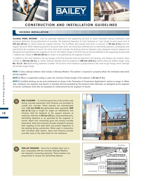
ComSlab PANEL DECKING – shall be positively fastened to the supporting structure to avoid movement during <strong>construction</strong> <strong>and</strong><br />
excessive deflection during placement of concrete. The fastening frequency of main fasteners is 1 per trough at each panel end at<br />
610 mm (24 in.) on centre along the support structure. The ComSlab deck panels shall bear a minimum of 50 mm (2 in.) onto the<br />
support structure. When fastening panels to structural steel work, use heavy-duty shotfired pins or self-drilling fasteners as designed <strong>and</strong><br />
specified by the engineer of record. For brick, block <strong>and</strong> concrete, the decking shall be fastened using adequate masonry fasteners as<br />
designed <strong>and</strong> specified by the engineer of record. The bottom flange of the End Closure shall be fastened to the supporting structure with<br />
1 fastener per module at 610 mm (24 in.) on centre, or as specified by the engineer of record.<br />
In addition to the main fasteners, the top flanges of the End Closures shall be fastened to the decking, one fastener per module, either<br />
centred or 610 mm (24 in.) on centre. Side-lap Washers shall be fastened at 350 mm (13.8 in.) centres along the bottom trough, using<br />
No. 14 1/4 - 14 x 1 self-drilling fasteners or better. The location of the fasteners is prepunched on the male trough flange, which overlaps<br />
the female trough flange.<br />
www.bmp-group.com<br />
10<br />
NOTE 1: Every side-lap fastener shall include a Side-lap Washer. This washer is required to properly attach the individual steel deck<br />
panels together.<br />
NOTE 2: When a suspended ceiling is used, the minimum thread length of the fastener is 25 mm (1 in.).<br />
NOTE 3: ComSlab decking can be end cantilevered as shown in the “Examples of Construction Applications” section on page 14. When<br />
side cantilevers are required, stub beams or brackets shall be provided by the structural steel fabricator, as designed by the engineer<br />
of record. Cantilevers shall also be assessed for reinforcement by the engineer of record.<br />
1<br />
END CLOSURES – To minimize grout loss at the profile ends<br />
during concrete placement, End Closures are provided to<br />
contain the concrete. These closures are manufactured<br />
from 1.52 mm (0.060 in.) galvanized steel, generally 1830<br />
mm (6 ft) long or longer for angle cut <strong>installation</strong>s. End<br />
Closures shall be fastened to the support structure at<br />
maximum intervals of 610 mm (24 in.), using shot-fired pins,<br />
self-drilling fasteners or as specified by the engineer of<br />
record. Apart from minimizing grout loss during concrete<br />
placement, these End Closures provide strength to prevent<br />
web crippling of the steel deck <strong>and</strong> proper alignment of<br />
the decking during <strong>construction</strong>. When used in conjunction<br />
with hot-rolled steel beams, these End Closures provide<br />
concrete cover to the steel beam for fire resistance.<br />
2<br />
SIDE-LAP WASHERS – Since the ComSlab deck acts in<br />
part compositely with the concrete, Side-lap Washers<br />
are important connecting elements. These washers are<br />
prepunched to receive the self-drilling fastener.
CONSTRUCTION AND INSTALLATION GUIDELINES<br />
DECKING INSTALLATION<br />
3<br />
PERIMETER TRIMS – Are required for the retention of wet concrete to the correct level<br />
at the decked floor perimeters <strong>and</strong> designed openings. They are supplied in 3 m (10<br />
ft) lengths of galvanized steel. Perimeter Trims are usually fastened by shot-fired pins<br />
to the structural steel or by self-drilling fasteners to the support structure at 610 mm (24<br />
in.) on centre, or as specified by the engineer of record.<br />
4<br />
RESTRAINT STRAPS – The top of the perimeter edge trim is connected to the decking<br />
with Restraint Straps at approximately 400 mm (16 in.) on centre using either pop rivets<br />
or self-drilling fasteners. The Restraint Strap can be adjusted to suit the pitch <strong>and</strong><br />
alignment of the perimeter edge trim.<br />
5<br />
PENETRATIONS – Penetrations through the floor decking shall be cut after the concrete<br />
has cured. Before placing concrete, any openings shall be boxed out with form work<br />
as specified by the engineer of record. The following <strong>guidelines</strong> are suggested for isolated<br />
openings at right angles to the deck span, or as specified by the engineer of record:<br />
• Up to 300 mm (12 in.) square penetrations centred on the top of the profile of the<br />
deck is acceptable without additional reinforcement, other than the minimum<br />
shrinkage <strong>and</strong> temperature mesh.<br />
• Up to 425 mm (16.7 in.) width by 1000 mm (39.4 in.) length opening with additional<br />
reinforcement.<br />
• Openings larger than 425 mm (16.7 in.) require structural steel framing as specified<br />
by the engineer of record.<br />
• Close grouping of openings transverse to the profile shall be treated as one<br />
opening, requiring additional reinforcement as specified by the engineer of record.<br />
• After the slab has reached 75% of the required concrete compressive strength, a<br />
nibbler, power saw or coring machine can be used to cut out openings in the top<br />
profile with the approval by the engineer of record.<br />
www.bmp-group.com<br />
11<br />
6<br />
COLUMNS AND ComSlab DECKING – The steel deck sheeting can be cut <strong>and</strong> fitted<br />
to accommodate various column shapes to minimize grout loss. Where no supporting<br />
steel work is provided, steel angle brackets shall be provided to support the steel<br />
decking, as specified by the engineer of record.<br />
7<br />
RIB REINFORCEMENT AND MESH PLACEMENT – The ComSlab design requires that<br />
one steel reinforcing bar be placed in each rib profile. The bar size, as shown in the<br />
load tables, can vary from 10 mm (0.394 in.) to 35 mm (1.38 in.) in diameter. The bars<br />
shall be placed on Rebar Supports which ensure a 40 mm (1.57 in.) spacing from<br />
the bottom flange to the underside of the reinforcing bars. Spacing of the Rebar<br />
Supports shall be in accordance with good practice <strong>guidelines</strong>, <strong>and</strong> not exceeding<br />
1220 mm (48 in.) on centre. To ensure both vertical <strong>and</strong> horizontal stability during<br />
concrete placement, the reinforcing bars shall be tied down periodically through the<br />
Side-lap Washers with 1.21 mm (0.0476 in.) diameter tie wiring. It is recommended<br />
that a minimum st<strong>and</strong>ard shrinkage <strong>and</strong> temperature reinforcing mesh of<br />
152x152xMW18.7xMW18.7 (6x6x6/6) be placed above the top of the steel decking<br />
<strong>and</strong> positioned towards the top of the slab, or as specified by the engineer of record.
CONSTRUCTION AND INSTALLATION GUIDELINES<br />
DECKING INSTALLATION<br />
8<br />
CONCRETE PLACEMENT – Concrete shall be placed in accordance with CSA A23.1-09.<br />
Before starting concrete placement, the steel decking shall be cleared of dirt,<br />
grease <strong>and</strong> debris, which could adversely influence the composite slab<br />
performance. Care shall be taken to avoid concrete heaping in any area during<br />
concrete placement. Typical <strong>construction</strong> live loads have been accounted for in the<br />
load tables. Should additional <strong>construction</strong> loading be required, approval by the<br />
engineer of record is required.<br />
www.bmp-group.com<br />
12<br />
9<br />
10<br />
TEMPORARY SUPPORTS – When the design span exceeds the maximum unshored<br />
span shown in the load tables, the wet concrete weight <strong>and</strong> <strong>construction</strong> loads shall<br />
be supported by adding temporary supports (shoring), as designed by the engineer<br />
of record. Where temporary supports are required, it is important that:<br />
• Beams <strong>and</strong> the support structure have adequate strength to support the<br />
<strong>construction</strong> loads as designed <strong>and</strong> specified by the engineer of record.<br />
• Shoring is normally placed at midspan or at other suitable intervals, as required.<br />
• Shoring beams shall provide a minimum bearing width of 100 mm (4 in.).<br />
• The shoring structure shall remain in place until the concrete has reached 75% of<br />
its design strength, or as specified by the engineer of record.<br />
HANGER SYSTEM – The geometry of the ribs allows for the suspension of services from<br />
the profile top flange between ribs. Pre-set threaded rod hangers are easily installed<br />
before the concrete is placed. Consult your mechanical <strong>and</strong> electrical consultants, <strong>and</strong><br />
<strong>installation</strong> contractors for accepted specifications.<br />
11<br />
SERVICE HOLES – Refer to table on page 18 for size <strong>and</strong> location of round holes<br />
through ComSlab ribs. Sleeves shall be fastened in place before concrete placement.<br />
Cut-out of holes shall be done only after the concrete has reached 75% of its design<br />
strength, or as specified by the engineer of record.<br />
12<br />
CEILING HANGER SYSTEMS – Ceilings can be suspended directly from the bottom of<br />
the steel deck.<br />
THE ComSlab DRY DECK<br />
The ComSlab system can be used as a non-composite steel deck only without concrete/rebar<br />
as a roofing solution or residential flooring system (when span/load permits). Kindly contact<br />
your BMP Technical Sales Representative for more information. Load tables with single, double<br />
<strong>and</strong> triple span conditions are available.
CONSTRUCTION AND INSTALLATION GUIDELINES<br />
END CLOSURE<br />
Install with mechanical fasteners to any lateral beam or bearing wall substrate at minimum<br />
610 mm (24 in.) on centre.<br />
PERIMETER TRIM<br />
Install Perimeter Trims for concrete containment <strong>and</strong> alignment. The top edge is<br />
used as a screed guide to achieve the overall required concrete slab depth.<br />
PLACING OF ComSlab DECK<br />
Install the deck progressively (male to female flange overlap) <strong>and</strong> fasten at<br />
350 mm (13.8 in.) on centre with Side-lap Washers <strong>and</strong> self-drilling fasteners.<br />
TEMPORARY SHORING<br />
Install in accordance with load tables based on maximum unshored span condition.<br />
The engineer of record shall approve shoring requirement <strong>and</strong> <strong>installation</strong>.<br />
www.bmp-group.com<br />
IN-FLOOR RADIANT HEATING<br />
13<br />
Install flat sheets of wire mesh or other equivalent material,<br />
i.e. 10 mm reinforcing bar @ 560 mm (22 in.) on centre commonly used.<br />
PLACEMENT OF CONCRETE<br />
Place concrete uniformly <strong>and</strong> screed to top of perimeter trims <strong>and</strong> avoid concrete<br />
heaping. Cylinder strength shall not be less than 30 MPa (4.35 ksi), with a maximum<br />
aggregate size of 20 mm (0.75 in.).<br />
UNDERSIDE VIEW<br />
The installed ribbed ceiling provides suitable substrate for direct finishing; applying<br />
additional fire safety protection; enhanced acoustical treatment <strong>and</strong> finishing with a<br />
variety of finished ceiling materials.