Roller Conveyor Chain - Tsubaki
Roller Conveyor Chain - Tsubaki
Roller Conveyor Chain - Tsubaki

You also want an ePaper? Increase the reach of your titles
YUMPU automatically turns print PDFs into web optimized ePapers that Google loves.
TSUBAKI<br />
ENGINEERING CLASS CHAIN<br />
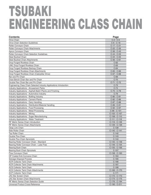
Contents<br />
Page<br />
Drive <strong>Chain</strong> C-2 - C-5<br />
Drive <strong>Chain</strong> Selection Guidelines C-6 - C-16<br />
<strong>Roller</strong> <strong>Conveyor</strong> <strong>Chain</strong> C-17 - C-21<br />
<strong>Roller</strong> <strong>Conveyor</strong> <strong>Chain</strong> Attachments C-22 - C-35<br />
Apron <strong>Conveyor</strong> <strong>Chain</strong> C-36 - C-43<br />
<strong>Roller</strong> <strong>Conveyor</strong> <strong>Chain</strong> Selection Guidelines C-44 - C-53<br />
Steel Bushed <strong>Chain</strong> C-54 - C-55<br />
Steel Bushed <strong>Chain</strong> Attachments C-56 - C-61<br />
Drop Forged Rivetless <strong>Chain</strong> C-62<br />
UWL Drop Forged Rivetless <strong>Chain</strong> C-63<br />
Drop Forged Rivetless Barloop <strong>Chain</strong> C-64<br />
Drop Forged Rivetless <strong>Chain</strong> Attachments C-65 - C-66<br />
Drop Forged Rivetless <strong>Chain</strong> (Caterpillar Drive) C-67 - C-68<br />
Bar and Pin <strong>Chain</strong> C-69<br />
Draw Bench <strong>Chain</strong> Bar and Pin <strong>Chain</strong> C-70<br />
Double Flex <strong>Chain</strong> Bar and Pin <strong>Chain</strong> C-71 - C-72<br />
Engineering Class <strong>Chain</strong> Selected Industry Applications Introduction C-73<br />
Industry Applications - Amusement Parks C-74<br />
Industry Applications - Asphalt Batch Plants and Finishing C-75 - C-78<br />
Industry Applications - Automotive Industry C-79<br />
Industry Applications - Bottling Industry C-80 - C-81<br />
Industry Applications - Cement Plants C-82 - C-86<br />
Industry Applications - Dairy Handling C-87 - C-88<br />
Industry Applications - Distribution/Material Handling C-89 - C-91<br />
Industry Applications - Food Processing C-92 - C-97<br />
Industry Applications - Metal Processing C-98 - C-101<br />
Industry Applications - Mining C-102 - C-107<br />
Industry Applications - Sugar Manufacturing C-108 - C-110<br />
Industry Applications - Water Treatment C-111 - C-118<br />
RF Metric Series <strong>Chain</strong> Introduction C-119 - C-128<br />
RF Metric Series <strong>Chain</strong> Attachments C-129 - C-138<br />
Deep Link <strong>Chain</strong> C-139<br />
Side <strong>Roller</strong> <strong>Chain</strong> C-140 - C-141<br />
Top <strong>Roller</strong> <strong>Chain</strong> C-142<br />
Double Plus <strong>Chain</strong> C-143<br />
Double Plus <strong>Chain</strong> Sprockets C-144<br />
Bearing <strong>Roller</strong> <strong>Conveyor</strong> <strong>Chain</strong> - Standard C-145 - C-148<br />
Bearing <strong>Roller</strong> <strong>Conveyor</strong> <strong>Chain</strong> - Lube Free C-149 - C-154<br />
Bearing Bush <strong>Chain</strong> C-155 - C-156<br />
Bearing Bush <strong>Chain</strong> Sprockets C-157<br />
Flow <strong>Conveyor</strong> <strong>Chain</strong> C-158 - C-163<br />
DP Coated Anti-Corrosive <strong>Chain</strong> C-164<br />
Sewage Disposal Process C-165<br />
ACR Collector Tank <strong>Chain</strong> C-166<br />
ACR Collector Tank <strong>Chain</strong> Attachments C-167<br />
ACS Collector Tank <strong>Chain</strong> C-168<br />
ACS Collector Tank <strong>Chain</strong> Attachments C-169 - C-170<br />
ACP Collector Tank <strong>Chain</strong> C-171<br />
JAC Bar Screen <strong>Chain</strong> C-172 - C-173<br />
JAC Bar Screen <strong>Chain</strong> Attachments C-174 - C-175<br />
RF Metric Series <strong>Chain</strong> Selection Guide C-176 - C-194<br />
Universal Product Cross-Reference C-195 - C-211
Drive <strong>Chain</strong><br />
ENGINEERING CLASS DRIVE CHAIN<br />
Keep Your Operation Moving with<br />
<strong>Tsubaki</strong> <strong>Chain</strong><br />
<strong>Tsubaki</strong> Drive <strong>Chain</strong>s are designed to exceed the listed ultimate strength ratings. These ratings are very significant. <strong>Chain</strong>s with<br />
greater ultimate strength have higher actual yield and greater fatigue strength. With <strong>Tsubaki</strong> chains, you get extra reserve strength to<br />
withstand high shock loads.<br />
Precision Manufacturing Means<br />
Greater Fatigue Strength<br />
<strong>Tsubaki</strong> Engineering Class Drive <strong>Chain</strong>s are built to withstand the most rugged conditions. We use the latest manufacturing<br />
and heat-treating techniques to manufacture every component. Each component is carefully machined to close tolerances to ensure<br />
precise pitch control for smooth sprocket/chain interaction. That means longer service life for chain and sprockets.<br />
Engineering Class <strong>Chain</strong><br />
Add the Power of Alloy<br />
When parts require extra hardness, we use alloy steel to make the components. This provides more uniform core strength, which is<br />
particularly important for heavy duty applications. Every <strong>Tsubaki</strong> Drive <strong>Chain</strong> with an ultimate strength rating higher than 112,000<br />
pounds is made entirely of alloy steel. All <strong>Tsubaki</strong> Drive <strong>Chain</strong>s are furnished with alloy steel pins.<br />
Reduce Maintenance Costs and Downtime<br />
<strong>Tsubaki</strong> Drive <strong>Chain</strong>s stand up to the toughest environments for hour after hour of uninterrupted service.<br />
• Optimum strength<br />
• Fatigue resistant<br />
• Pre-tested<br />
• Alloy steel parts<br />
• Press fit construction<br />
• Accurate pitch control<br />
Your equipment is on the line. Count on <strong>Tsubaki</strong> <strong>Chain</strong>.<br />
C-2
Drive <strong>Chain</strong><br />
Quality Components<br />
High-Strength Sidebars<br />
Sidebars for <strong>Tsubaki</strong> Drive <strong>Chain</strong>s with an ultimate strength<br />
rating higher than 112,000 pounds are manufactured from<br />
alloy steel and are through-hardened. This adds strength and<br />
extends the service life of the chain. In addition, our advanced<br />
manufacturing techniques ensure accurate hole size and precise<br />
pitch control, distributing the load equally and providing<br />
smooth sprocket interaction.<br />
Alloy Steel Induction Hardened Pins<br />
All Drive <strong>Chain</strong> pins are made from alloy steel and are<br />
through-hardened for toughness and strength. In addition,<br />
chains designed for heavy duty power shovel applications<br />
have ground bearing surfaces and full round induction hardening.<br />
This provides the best combination of high yield strength<br />
and superior wear resistance.<br />
Precision Machined Bushings<br />
Bushings for Drive <strong>Chain</strong> are precision machined to provide<br />
smooth bearing surfaces—that means less resistance on-line.<br />
They are through-hardened or case hardened to meet your<br />
application. The result is smooth riding bushings that last.<br />
Shock-Resistant <strong>Roller</strong>s<br />
Our rollers are made from a high quality material for use<br />
when critical tolerances and superior finish are required. Then<br />
they are through-hardened to withstand high shock loads. For<br />
chains with high ultimate strength ratings, rollers are typically<br />
made from alloy steel.<br />
Engineering Class <strong>Chain</strong><br />
C-3
Drive <strong>Chain</strong><br />
offset sidebar style<br />
T<br />
Pitch<br />
Pitch<br />
E<br />
D<br />
G<br />
C<br />
H<br />
B<br />
Engineering Class <strong>Chain</strong><br />
straight sidebar style<br />
T<br />
D<br />
E<br />
G<br />
C<br />
H<br />
Pitch<br />
Pitch<br />
B<br />
“U” sidebar style<br />
C-4
Drive <strong>Chain</strong><br />
Drive <strong>Chain</strong> Specifications<br />
All dimensions are in inches unless otherwise indicated.<br />
Stocked<br />
Pin <strong>Roller</strong> Sidebar Bushing Lengths<br />
Pin Pin Avg.<br />
End Head In- Ult.<br />
<strong>Chain</strong> ANSI to to side Stgth.<br />
No. Pitch Sty. 1 No. CL CL Wdth. Dia. Sty. 2 Matl. 3 Dia. Matl. 3 Hgt. Th. Matl. 3 Dia. Matl. 3 Pitches Feet (lbs.)<br />
B C E G D H T<br />
Max.<br />
Work<br />
Load<br />
(lbs.)<br />
Approx.<br />
Wgt.<br />
(lbs./ft.)<br />
US-2065 2.000 O 1.66 1.44 1.27 .59 K AHT<br />
RO-3140 1.750 U 1.34 1.12 1.00 .48 K AHT<br />
RO-3160 2.000 U 1.53 1.31 1.25 .54 K AHT<br />
RO-3180 2.250 U 1.72 1.47 1.43 .69 K AHT<br />
RO-25H 2.500 O 1.95 1.70 1.50 .65 K AHTIH<br />
520RX 2.563 O 1.44 1.22 1.06 .50 A CHT<br />
US-882 2.609 O 1.44 1.25 1.13 .44 K CHT<br />
US-3011 3.067 O 2512 2.13 1.72 1.56 .75 K AHTIH<br />
US-1030 3.075 O 1.88 1.56 1.50 .63 K AHT<br />
US-1031 3.075 O 1.88 1.59 1.50 .63 K AHT<br />
US-3075 3.075 O 2.00 1.68 1.50 .65 K AHT<br />
US-3514 3.500 O 2814 2.34 1.97 1.50 .88 K AHT<br />
US-1241 4.063 O 2.59 2.19 1.94 .88 K AHTIH<br />
US-1242 4.063 O 2.56 2.19 1.94 .88 K AHTIH<br />
US-1245 4.073 O 3315 2.75 2.38 1.94 .94 K AHTIH<br />
US-4121 4.090 O 2.75 2.38 1.94 1.00 K AHTIH<br />
US-4122 4.090 O 2.75 2.38 1.94 1.00 K AHTIH<br />
US-4522 4.500 O 3618 2.88 2.44 2.06 1.10 K AHTIH<br />
US-5031 5.000 O 4020 3.38 3.06 2.75 1.25 K AHTIH<br />
US-5035 5.000 O 3.50 3.06 2.56 1.38 K AHTIH<br />
US-5542 5.500 O 3.88 3.40 3.00 1.50 K AHTIH<br />
US-5738 5.750 O 3.69 3.31 3.00 1.50 K AHTIH<br />
US-6042 6.000 O 4824 3.88 3.40 3.00 1.50 K AHTIH<br />
US-6066 6.000 O 3.88 3.38 3.00 1.75 K AHTIH<br />
US-64S 2.500 S 2.00 1.69 1.50 .88 K AHT<br />
344SXX 3.000 S 2.75 2.38 1.94 .94 K AHTIH<br />
US-4031 4.000 S 3.38 2.91 2.75 1.25 K AHTIH<br />
US-1353 4.090 S 3.13 2.69 2.25 1.31 K AHTIH<br />
US-5042 5.000 S 3.88 3.40 3.00 1.50 K AHTIH<br />
US-6566 6.500 S 4.38 3.95 3.25 1.75 K AHTIH<br />
US-7080 7.000 S 4.19 3.81 3.25 2.13 K AHTIH<br />
1.13 AHT 1.63 .31 AHT .81 ACH<br />
1.00 AHT 1.70 .22 AHT .70 ACH<br />
1.13 AHT 1.94 .25 AHT .80 ACH<br />
1.41 AHT 2.13 .28 AHT 1.00 CHT<br />
1.25 AHT 1.63 .38 AHT .91 ACH<br />
1.13 CHT 1.25 .25 CHT .75 CCH<br />
.88 AHT 1.13 .25 CHT .64 CCH<br />
1.63 AHT 2.25 .38 AHT 1.13 ACH<br />
1.25 AHT 1.50 .31 HC .91 ACH<br />
1.25 AHT 1.50 .31 CHT .91 ACH<br />
1.25 AHT 1.75 .38 AHT .91 ACH<br />
1.75 AHT 2.25 .50 AHT 1.25 ACH<br />
1.75 AHT 2.25 .50 CHT 1.25 CCH<br />
1.75 AHT 2.25 .50 AHT 1.25 ACH<br />
1.78 AHT 2.38 .56 AHT 1.31 ACH<br />
1.88 AHT 2.75 .56 AHT 1.49 AHT<br />
2.00 AHT 2.75 .56 AHT 1.49 AHT<br />
2.25 AHT 3.00 .56 AHT 1.62 AHT<br />
2.50 AHT 3.50 .63 AHT 1.75 AHT<br />
2.50 AHT 3.50 .75 AHT 1.88 AHT<br />
3.00 AHT 4.00 .75 AHT 2.00 AHT<br />
3.00 AHT 4.00 .69 AHT 2.00 AHT<br />
3.00 AHT 4.00 .75 AHT 2.00 AHT<br />
— — 4.75 .75 AHT 3.00 AHT<br />
1.56 AHT 2.13 .38 AHT 1.19 ACH<br />
1.78 AHT 2.38 .56 AHT 1.31 AHT<br />
2.50 AHT 3.50 .63 AHT 1.75 AHT<br />
2.63 AHT 3.50 .63 AHT 1.88 ACH<br />
3.00 AHT 4.00 .75 AHT 2.00 AHT<br />
3.50 AHT 6.00 .88 AHT 2.44 AHT<br />
4.50 AHT 6.00 .88 AHT 3.13 AHT<br />
60 10.00 65,000 4,000 7.6<br />
69 10.00 52,800 2,500 5.2<br />
60 10.00 67,300 3,450 6.7<br />
53 10.00 80,000 4,800 9.6<br />
48 10.00 87,000 4,900 9.2<br />
47 10.00 25,000 2,800 4.8<br />
46 10.00 26,000 2,500 3.6<br />
39 10.00 110,000 6,100 12.0<br />
39 10.00 28,000 4,650 7.0<br />
39 10.00 48,000 4,650 7.0<br />
39 10.00 75,000 5,100 9.6<br />
34 9.90 140,000 7,700 16.1<br />
30 10.20 112,000 9,000 16.3<br />
30 10.20 140,000 9,000 16.1<br />
30 10.20 170,000 10,100 18.0<br />
30 10.20 210,000 10,700 13.6<br />
30 10.20 210,000 10,700 14.0<br />
27 10.10 220,000 12,300 25.4<br />
24 10.00 310,000 17,500 34.0<br />
24 10.00 350,000 19,600 38.1<br />
62 28.40 420,000 23,600 49.1<br />
21 10.10 380,000 23,000 46.0<br />
20 10.00 420,000 23,600 45.0<br />
57 28.50 600,000 27,600 51.7<br />
48 10.00 125,000 6,900 13.1<br />
40 10.00 170,000 10,050 22.0<br />
30 10.00 310,000 17,500 40.0<br />
30 10.20 210,000 16,000 37.6<br />
24 10.00 420,000 23,600 53.0<br />
36 19.50 600,000 30,600 71.1<br />
24 14.00 800,000 37,150 89.6<br />
Engineering Class <strong>Chain</strong><br />
1 Style: O= offset sidebar; S= straight sidebar<br />
2 Pin style: K = Full round; A = Double flat.<br />
3 Material: HC = High carbon; CHT = Carbon heat-treated; AHT = Alloy heat-treated; AHTIH = Alloy heat-treated and induction hardened; CCH = Carbon case hardened;<br />
ACH = Alloy case hardened.<br />
To locate compatible sprockets for your chain, refer to the Product Cross-Reference at the back of this section.<br />
Note: Dimensions are subject to change. Contact <strong>Tsubaki</strong> Technical Support to obtain certified prints for design and construction.<br />
C-5
Drive <strong>Chain</strong><br />
Selection Guidelines<br />
SELECTION GUIDELINES<br />
There are two methods to determine the right drive chain for your application: Standard and Working Load. To determine the suggested<br />
chain, follow Steps 1-10 of the Standard Selection Procedure on pages C-6 through C-8. An example procedure is shown on<br />
page C-16. Each selection procedure is intended to be used for Engineering Class Drive <strong>Chain</strong> (ASME/ANSI Standard B29.10).<br />
STANDARD SELECTION PROCEDURE<br />
Step 1: Determine Class of Driven Load<br />
From the Application Classifications Table 1 determine the class of the driven load: uniform load, moderate shock, heavy shock.<br />
Table 1 — Application Classifications<br />
Load Load Load Load<br />
Application Class 1 Application Class 1 Application Class 1 Application Class 1<br />
Engineering Class <strong>Chain</strong><br />
Agitators<br />
Pure Liquids . . . . . . . . . . . . . . .U<br />
Liquids and Solids . . . . . . . . . .M<br />
Liquids – Variable Density . . . .M<br />
Blowers<br />
Centrifugal . . . . . . . . . . . . . . . .U<br />
Lobe . . . . . . . . . . . . . . . . . . . . .M<br />
Vane . . . . . . . . . . . . . . . . . . . . .U<br />
Brewing and Distilling<br />
Bottling Machinery . . . . . . . . . .U<br />
Brew Kettles – Cont. Duty . . . . .U<br />
Cookers – Cont. Duty . . . . . . . .U<br />
Mash Tubs – Cont. Duty . . . . . .U<br />
Scale Hopper, Freq. Starts . . . .M<br />
Can Filling Machines . . . . . . . .U<br />
Cane Knives . . . . . . . . . . . . . . .M<br />
Car Dumpers . . . . . . . . . . . . . . .H<br />
Car Pullers . . . . . . . . . . . . . . . .M<br />
Clarifiers . . . . . . . . . . . . . . . . . .U<br />
Classifiers . . . . . . . . . . . . . . . . .M<br />
Clay Working Machinery<br />
Brick Press . . . . . . . . . . . . . . . .H<br />
Briquette Machine . . . . . . . . . . .H<br />
Clay Working Machinery . . . . . .M<br />
Pub Mill . . . . . . . . . . . . . . . . . . .M<br />
Compressors<br />
Centrifugal . . . . . . . . . . . . . . . .U<br />
Lobe . . . . . . . . . . . . . . . . . . . . .M<br />
Reciprocating, Multi-Cylinder . .M<br />
Reciprocating, Single-Cylinder .H<br />
<strong>Conveyor</strong>s – Uniformly<br />
Loaded or Fed<br />
Apron . . . . . . . . . . . . . . . . . . . .U<br />
Assembly . . . . . . . . . . . . . . . . .U<br />
Belt . . . . . . . . . . . . . . . . . . . . . .U<br />
Bucket . . . . . . . . . . . . . . . . . . . .U<br />
<strong>Chain</strong> . . . . . . . . . . . . . . . . . . . .U<br />
Flight . . . . . . . . . . . . . . . . . . . . .U<br />
<strong>Conveyor</strong>s – Uniformly<br />
Loaded or Fed (Continued)<br />
Oven . . . . . . . . . . . . . . . . . . . . .U<br />
Screw . . . . . . . . . . . . . . . . . . . .U<br />
<strong>Conveyor</strong>s – Heavy Duty<br />
Not Uniformly Fed<br />
Apron . . . . . . . . . . . . . . . . . . . .M<br />
Assembly . . . . . . . . . . . . . . . . .M<br />
Belt . . . . . . . . . . . . . . . . . . . . . .M<br />
Bucket . . . . . . . . . . . . . . . . . . . .M<br />
<strong>Chain</strong> . . . . . . . . . . . . . . . . . . . .M<br />
Flight . . . . . . . . . . . . . . . . . . . . .M<br />
Live Roll . . . . . . . . . . . . . . . . . .M<br />
Oven . . . . . . . . . . . . . . . . . . . . .M<br />
Reciprocating . . . . . . . . . . . . . .H<br />
Screw . . . . . . . . . . . . . . . . . . . .M<br />
Shaker . . . . . . . . . . . . . . . . . . .H<br />
Cranes<br />
Main Hoists . . . . . . . . . . . . . . . .U<br />
Bridge Travel . . . . . . . . . . . . . .M<br />
Trolley Travel . . . . . . . . . . . . . .M<br />
Crusher<br />
Ore . . . . . . . . . . . . . . . . . . . . . .H<br />
Stone . . . . . . . . . . . . . . . . . . . .H<br />
Sugar . . . . . . . . . . . . . . . . . . . .M<br />
Dredges<br />
Cable Reels . . . . . . . . . . . . . . .M<br />
<strong>Conveyor</strong>s . . . . . . . . . . . . . . . . .M<br />
Cutter Head Drives . . . . . . . . . .H<br />
Jig Drives . . . . . . . . . . . . . . . . .H<br />
Maneuvering Winches . . . . . . .M<br />
Pumps . . . . . . . . . . . . . . . . . . .M<br />
Screen Drive . . . . . . . . . . . . . . .H<br />
Stackers . . . . . . . . . . . . . . . . . .M<br />
Utility Winches . . . . . . . . . . . . .M<br />
Dry Dock Cranes<br />
Main Hoist, Auxiliary Hoist,<br />
Boom (Luffing) . . . . . . . . . . . .U<br />
Dry Dock Cranes (Continued)<br />
Rotating (Swing or Slew) . . . . .M<br />
Tracking (Drive Wheels) . . . . . .H<br />
Elevators<br />
Bucket – Uniform Load . . . . . . .U<br />
Bucket – Heavy Load . . . . . . . .M<br />
Bucket – Cont.<br />
Centrifugal Discharge . . . . . . .U<br />
Escalators . . . . . . . . . . . . . . . . .U<br />
Freight . . . . . . . . . . . . . . . . . . .M<br />
Gravity Discharge . . . . . . . . . . .U<br />
Man Lifts . . . . . . . . . . . . . . . . . .H<br />
Passenger . . . . . . . . . . . . . . . . .H<br />
Fans<br />
Centrifugal . . . . . . . . . . . . . . . .U<br />
Cooling Towers – Induced Draft U<br />
Cooling Towers – Forced Draft .U<br />
Induced Draft . . . . . . . . . . . . . .M<br />
Large (Mine, etc.) . . . . . . . . . . .M<br />
Large (Industrial) . . . . . . . . . . .M<br />
Light (Small Diameter) . . . . . . .U<br />
Feeders<br />
Apron . . . . . . . . . . . . . . . . . . . .M<br />
Belt . . . . . . . . . . . . . . . . . . . . . .M<br />
Disc . . . . . . . . . . . . . . . . . . . . . .U<br />
Reciprocating . . . . . . . . . . . . . .H<br />
Screw . . . . . . . . . . . . . . . . . . . .M<br />
Food Industry<br />
Beet Slicer . . . . . . . . . . . . . . . .M<br />
Cereal Cooker . . . . . . . . . . . . . .U<br />
Dough Mixer . . . . . . . . . . . . . . .M<br />
Meat Grinders . . . . . . . . . . . . . .M<br />
Generators (Not Welding) . . . .U<br />
Hammer Mills . . . . . . . . . . . . . .H<br />
Hoists<br />
Heavy Duty . . . . . . . . . . . . . . . .H<br />
Medium Duty . . . . . . . . . . . . . .M<br />
Skip Hoist . . . . . . . . . . . . . . . . .M<br />
Laundry Washers<br />
Reversing . . . . . . . . . . . . . . . . .M<br />
Laundry Tumblers . . . . . . . . . .M<br />
Line Shafts<br />
Driving Processing Equipment .M<br />
Light . . . . . . . . . . . . . . . . . . . . .U<br />
Other Line Shafts . . . . . . . . . . .U<br />
Lumber Industry<br />
Barkers – Hydraulic,<br />
Mechanical . . . . . . . . . . . . . . .M<br />
Burner <strong>Conveyor</strong> . . . . . . . . . . .M<br />
<strong>Chain</strong> Saw and Drag Saw . . . . .H<br />
<strong>Chain</strong> Transfer . . . . . . . . . . . . .H<br />
Craneway Transfer . . . . . . . . . .H<br />
De-barking Drum . . . . . . . . . . .H<br />
Edger Feed . . . . . . . . . . . . . . . .M<br />
Gang Feed . . . . . . . . . . . . . . . .M<br />
Green <strong>Chain</strong> . . . . . . . . . . . . . . .M<br />
Live Rolls . . . . . . . . . . . . . . . . .H<br />
Log Deck . . . . . . . . . . . . . . . . . .H<br />
Log Haul – Incline . . . . . . . . . . .H<br />
Log Haul – Well Type . . . . . . . .H<br />
Log Turning Device . . . . . . . . . .H<br />
Main Log <strong>Conveyor</strong> . . . . . . . . . .H<br />
Off Bearing Rolls . . . . . . . . . . .M<br />
Planer Feed <strong>Chain</strong>s . . . . . . . . .M<br />
Planer Floor <strong>Chain</strong>s . . . . . . . . .M<br />
Planer Tilting Hoist . . . . . . . . . .M<br />
Re-saw Merry-go-round<br />
<strong>Conveyor</strong> . . . . . . . . . . . . . . . .M<br />
Roll Cases . . . . . . . . . . . . . . . .H<br />
Slab <strong>Conveyor</strong> . . . . . . . . . . . . .H<br />
Small Waste <strong>Conveyor</strong> – Belt . .U<br />
Small Waste <strong>Conveyor</strong> – <strong>Chain</strong> M<br />
Sorting Table . . . . . . . . . . . . . . .M<br />
Tipple Hoist <strong>Conveyor</strong> . . . . . . .M<br />
Tipple Hoist Drive . . . . . . . . . . .M<br />
Transfer <strong>Conveyor</strong>s . . . . . . . . .M<br />
1 U = Uniform load; M = Moderate shock; H = Heavy shock.<br />
C-6
Drive <strong>Chain</strong><br />
Selection Guidelines<br />
Required Information for Drive Selection<br />
• Type of input horsepower (electric motor, internal combustion<br />
engine, etc.).<br />
• Type of equipment to be driven.<br />
• Horsepower to be transmitted.<br />
• Full load speed of the fastest running shaft (RPM).<br />
• Desired speed of the slow speed shaft (RPM).<br />
Note: If speeds are variable, determine maximum and<br />
minimum speed and HP to be transmitted at each speed.<br />
• Diameters of the driving and driven shafts.<br />
• Center to center distance of shafts.<br />
Note: If this dimension is adjustable, determine amount<br />
of adjustment.<br />
• Position of drive and space limitations, if any.<br />
• Proposed method of lubrication.<br />
• Conditions of drive. Drives with more than two sprockets,<br />
idlers, or unusual conditions such as severely abrasive or<br />
corrosive atmosphere, extremely high or low temperatures,<br />
severely fluctuating loads, frequent stops and starts, etc.,<br />
require special consideration. It is advisable to Contact<br />
<strong>Tsubaki</strong> Technical Support for selections of this nature.<br />
Table 1 — Application Classifications (Continued)<br />
Load Load Load Load<br />
Application Class 1 Application Class 1 Application Class 1 Application Class 1<br />
Lumber Industry (Continued) Mixers<br />
Transfer Rolls . . . . . . . . . . . . . .M<br />
Tray Drive . . . . . . . . . . . . . . . . .M<br />
Trimmer Feed . . . . . . . . . . . . . .M<br />
Waste <strong>Conveyor</strong> . . . . . . . . . . . .M<br />
Machine Tools<br />
Bending Roll . . . . . . . . . . . . . . .M<br />
Punch Press – Gear Driven . . .H<br />
Notching Press – Belt Driven . .H<br />
Plate Planers . . . . . . . . . . . . . .H<br />
Tapping Machine . . . . . . . . . . . .H<br />
Other Machine Tools –<br />
Main Drives . . . . . . . . . . . . . . .M<br />
Other Machine Tools –<br />
Auxiliary Drives . . . . . . . . . . . .U<br />
Metal Mills<br />
Draw Bench Carriage<br />
and Main Drive . . . . . . . . . . . .M<br />
Pinch, Dryer and Scrubber<br />
Rolls, Reversing . . . . . . . . . . .H<br />
Slitters . . . . . . . . . . . . . . . . . . . .M<br />
Table <strong>Conveyor</strong>s – Non-<br />
Reversing Group Drives . . . . .M<br />
Table <strong>Conveyor</strong>s – Non-<br />
Reversing Individual Drives . .H<br />
Table <strong>Conveyor</strong>s – Reversing . .H<br />
Wire Drawing and<br />
Flattening Machine . . . . . . . . .M<br />
Wire Winding Machine . . . . . . .M<br />
Mills, Rotary Type<br />
Ball . . . . . . . . . . . . . . . . . . . . . .M<br />
Cement Kilns . . . . . . . . . . . . . .M<br />
Dryers and Coolers . . . . . . . . . .M<br />
Kilns . . . . . . . . . . . . . . . . . . . . .M<br />
Pebble . . . . . . . . . . . . . . . . . . .M<br />
Rod, Plane and Wedge Bar . . .M<br />
Tumbling Barrels . . . . . . . . . . . .H<br />
Concrete Mixers – Cont. . . . . . .M<br />
Concrete Mixers – Intermittent .M<br />
Constant Density . . . . . . . . . . .U<br />
Variable Density . . . . . . . . . . . .M<br />
Oil Industry<br />
Chillers . . . . . . . . . . . . . . . . . . .M<br />
Oil Well Pumping . . . . . . . . . . .H<br />
Paraffin Filter Press . . . . . . . . .M<br />
Rotary Kilns . . . . . . . . . . . . . . .M<br />
Paper Mills<br />
Agitators (Mixers) . . . . . . . . . . .M<br />
Barker – Auxiliaries – Hydraulic M<br />
Barker – Mechanical . . . . . . . . .M<br />
Barking Drum . . . . . . . . . . . . . .H<br />
Beater and Pulper . . . . . . . . . . .M<br />
Bleacher . . . . . . . . . . . . . . . . . .U<br />
Calendars . . . . . . . . . . . . . . . . .M<br />
Calendars – Super . . . . . . . . . .H<br />
Converting Machine,<br />
Except Cutters, Platers . . . . . .M<br />
<strong>Conveyor</strong>s . . . . . . . . . . . . . . . . .U<br />
Couch . . . . . . . . . . . . . . . . . . . .M<br />
Cutters – Platers . . . . . . . . . . . .H<br />
Cylinders . . . . . . . . . . . . . . . . . .M<br />
Dryers . . . . . . . . . . . . . . . . . . . .M<br />
Felt Stretcher . . . . . . . . . . . . . .M<br />
Felt Whipper . . . . . . . . . . . . . . .H<br />
Jordans . . . . . . . . . . . . . . . . . . .H<br />
Log Haul . . . . . . . . . . . . . . . . . .H<br />
Presses . . . . . . . . . . . . . . . . . . .U<br />
Pulp Machine Reel . . . . . . . . . .M<br />
Stock Chests . . . . . . . . . . . . . .M<br />
Suction Roll . . . . . . . . . . . . . . . .U<br />
Washers and Thickeners . . . . .M<br />
Winders . . . . . . . . . . . . . . . . . . .U<br />
Printing Presses . . . . . . . . . . . .U<br />
Pullers<br />
Barge Haul . . . . . . . . . . . . . . . .H<br />
Pumps<br />
Centrifugal . . . . . . . . . . . . . . . .U<br />
Proportioning . . . . . . . . . . . . . .M<br />
Reciprocating – Single Acting,<br />
Three or more Cylinders . . . . .M<br />
Reciprocating – Double Acting,<br />
Two or more Cylinders . . . . . .M<br />
Reciprocating – Single Acting,<br />
One or Two Cylinders . . . . . . .M<br />
Reciprocating – Double Acting,<br />
Single Cylinder . . . . . . . . . . . .M<br />
Reciprocating –<br />
Rotary – Gear Type . . . . . . . .U<br />
Rotary – Lobe, Vane . . . . . . . .U<br />
Rubber and Plastics Industries<br />
Crackers . . . . . . . . . . . . . . . . . .H<br />
Laboratory Equipment . . . . . . .M<br />
Mixing Mills . . . . . . . . . . . . . . . .H<br />
Refiners . . . . . . . . . . . . . . . . . .M<br />
Rubber Calendars . . . . . . . . . .M<br />
Rubber Mill (Two on Line) . . . . .M<br />
Rubber Mill (Three on Line) . . .M<br />
Sheeter . . . . . . . . . . . . . . . . . . .M<br />
Tire Building Machines . . . . . . .M<br />
Tire and Tube Press Openers . .M<br />
Tubers and Strainers . . . . . . . .M<br />
Warming Mills . . . . . . . . . . . . . .M<br />
Sand Muller . . . . . . . . . . . . . . . .M<br />
Sewage Disposal Equipment<br />
Bar Screens . . . . . . . . . . . . . . .U<br />
Chemical Feeders . . . . . . . . . . .U<br />
Collectors . . . . . . . . . . . . . . . . .U<br />
Dewatering Screws . . . . . . . . . .M<br />
Scum Breakers . . . . . . . . . . . . .M<br />
Sewage Disposal<br />
Equipment (Continued)<br />
Slow or Rapid Mixers . . . . . . . .M<br />
Thickeners . . . . . . . . . . . . . . . .M<br />
Vacuum Filters . . . . . . . . . . . . .M<br />
Screens<br />
Air Washing . . . . . . . . . . . . . . . .U<br />
Rotary – Stone or Gravel . . . . .M<br />
Traveling Water Intake . . . . . . .U<br />
Slab Pushers . . . . . . . . . . . . . .M<br />
Steering Gear . . . . . . . . . . . . . .H<br />
Stokers . . . . . . . . . . . . . . . . . . .U<br />
Sugar Industry<br />
Cane Knives . . . . . . . . . . . . . . .M<br />
Crushers . . . . . . . . . . . . . . . . . .M<br />
Mills . . . . . . . . . . . . . . . . . . . . . .H<br />
Textile Industry<br />
Batchers . . . . . . . . . . . . . . . . . .M<br />
Calendars . . . . . . . . . . . . . . . . .M<br />
Cards . . . . . . . . . . . . . . . . . . . .M<br />
Dry Cans . . . . . . . . . . . . . . . . . .M<br />
Dryers . . . . . . . . . . . . . . . . . . . .M<br />
Dyeing Machinery . . . . . . . . . . .M<br />
Knitting Machines . . . . . . . . . . .M<br />
Looms . . . . . . . . . . . . . . . . . . . .M<br />
Mangles . . . . . . . . . . . . . . . . . .M<br />
Nappers . . . . . . . . . . . . . . . . . .M<br />
Pads . . . . . . . . . . . . . . . . . . . . .M<br />
Range Drives . . . . . . . . . . . . . .M<br />
Slashers . . . . . . . . . . . . . . . . . .M<br />
Soapers . . . . . . . . . . . . . . . . . .M<br />
Spinners . . . . . . . . . . . . . . . . . .M<br />
Tenter Frames . . . . . . . . . . . . .M<br />
Washers . . . . . . . . . . . . . . . . . .M<br />
Winders . . . . . . . . . . . . . . . . . .M<br />
Windless . . . . . . . . . . . . . . . . . .M<br />
Engineering Class <strong>Chain</strong><br />
1 U = Uniform load; M = Moderate shock; H = Heavy shock.<br />
C-7
Drive <strong>Chain</strong><br />
Selection Guidelines<br />
Step 2: Select Service Factor<br />
From the Service Factors Table 2 below, select the number<br />
under the type of input power and opposite the class<br />
of driven load that most closely relates to the application.<br />
Table 2 — Service Factors<br />
Type of Input Power<br />
Internal<br />
Internal<br />
Combustion<br />
Combustion<br />
Engine with Electric Engine with<br />
Type of Hydraulic Motor or Mechanical<br />
Driven Load Drive Turbine Drive<br />
Uniform 1.0 1.0 1.2<br />
Moderate Shock 1.2 1.3 1.4<br />
Heavy Shock 1.4 1.5 1.7<br />
Step 3: Calculate Design Horsepower<br />
Design Horsepower = HP x Service Factor.<br />
The Design Horsepower equals the Horsepower to be transmitted<br />
multiplied by the Service Factor selected in Step 2.<br />
The number of teeth in the large sprocket equals the RPM of the<br />
small sprocket times the number of teeth in the small sprocket<br />
divided by the RPM of the large sprocket. Note: Hardened teeth<br />
are suggested for sprockets with less than 15 teeth, speeds<br />
greater than 600 RPM, ratios over 4:1, or in heavy loading or<br />
abrasive environments.<br />
Step 7: Determine Suggested Minimum Center<br />
Distance; C = <strong>Chain</strong> Pitches<br />
C = 2N + n<br />
6<br />
This formula is to be used as a guide to MINIMUM center<br />
distances only. The final selection may vary slightly to suit<br />
clearance dimensions.<br />
Step 8: Check Final Drive Design<br />
Be sure that the sprockets and chain will fit into the<br />
available space.<br />
Step 9: Specify Sprockets<br />
Specify the sprockets selected. See Sprocket section in this<br />
catalog.<br />
Step 4: Select <strong>Chain</strong> Pitch<br />
Use the Quick Selection Chart (page C-11), to find chain pitch,<br />
as follows:<br />
• Locate the design horsepower from Step 4 on the<br />
vertical axis.<br />
• Locate the RPM of the small sprocket on the horizontal axis.<br />
• The intersection of the two lines (design horsepower and<br />
RPM) will be in an area designated with the suggested chain<br />
pitch. If the intersection is near the borderline of the pitch<br />
area, the pitches on both sides of the line should be evaluated<br />
to obtain the most suitable selection.<br />
• If the chain is not listed in the Quick Selection Chart, go to the<br />
Working Load Selection Guidelines.<br />
Step 5: Select Number of Teeth in Small Sprocket<br />
Horsepower Table Ratings for single strand chains are given<br />
on pages C-12 - C-15 for each chain pitch. Turn to the page<br />
giving the chain pitch obtained in Step 4 and select the number<br />
of teeth in the small sprocket:<br />
• Read down the column in the Horsepower Ratings Table<br />
under the RPM of the small sprocket until the requested HP<br />
Table Rating is located. Read across the table to the first column<br />
(Number of Teeth Small Sprocket). This is the smallest<br />
number of teeth to specify for this application.<br />
• Note the lubrication type specification in the table for this<br />
chain. This type of lubrication must be used to obtain reasonable<br />
service life.<br />
Step 6: Determine Number of Teeth in Large Sprocket<br />
Step 10: Calculate <strong>Chain</strong> Length<br />
To order the proper length of chain, use the following calculation:<br />
<strong>Chain</strong> Length in Pitches = S + 2C + K<br />
2 C<br />
• Add number of teeth in small sprocket and number of teeth in<br />
large sprocket to obtain S.<br />
• Subtract number of teeth in small sprocket from number of<br />
teeth in large sprocket to obtain value D. Find D in Table 3,<br />
and note corresponding value K.<br />
• Divide center distance in inches by pitch of chain, obtaining C.<br />
• Using these values, solve the formula above.<br />
<strong>Chain</strong> Length Length in Pitches x Pitch in Inches<br />
=<br />
in Feet 12<br />
A chain cannot contain a fractional part of a pitch. If the chain<br />
length obtained contains a fractional part of a pitch, use the next<br />
higher whole number.<br />
Glossary<br />
N = Number of teeth in large sprocket<br />
n = Number of teeth in small sprocket<br />
R = RPM large sprocket<br />
r = RPM small sprocket<br />
C = Shaft center distance in pitches<br />
S = N + n<br />
D = N - n<br />
N = rn R<br />
C-8
Drive <strong>Chain</strong><br />
Selection Guidelines<br />
Table 3 — K Values 1<br />
D K D K D K D K D K D K<br />
1 .03<br />
2 .10<br />
3 .23<br />
4 .41<br />
5 .63<br />
6 .91<br />
7 1.24<br />
8 1.62<br />
9 2.05<br />
10 2.53<br />
11 3.06<br />
12 3.65<br />
13 4.28<br />
14 4.96<br />
15 5.70<br />
16 6.48<br />
17 7.32<br />
18 8.21<br />
19 9.14<br />
20 10.13<br />
21 11.17<br />
22 12.26<br />
23 13.40<br />
24 14.59<br />
25 15.83<br />
26 17.12<br />
27 18.47<br />
28 19.86<br />
29 21.30<br />
30 22.80<br />
31 24.34<br />
32 25.94<br />
33 27.58<br />
34 29.28<br />
35 31.03<br />
36 32.83<br />
37 34.68<br />
38 36.58<br />
39 38.53<br />
40 40.53<br />
41 42.58<br />
42 44.68<br />
43 46.84<br />
44 49.04<br />
45 51.29<br />
46 53.60<br />
47 55.95<br />
48 58.36<br />
49 60.82<br />
50 63.33<br />
51 65.88<br />
52 68.49<br />
53 71.15<br />
54 73.86<br />
55 76.62<br />
56 79.44<br />
57 82.30<br />
58 85.21<br />
59 88.17<br />
60 91.19<br />
61 94.25<br />
62 97.37<br />
63 100.54<br />
64 103.75<br />
65 107.02<br />
66 110.34<br />
67 113.71<br />
68 117.13<br />
69 120.60<br />
70 124.12<br />
71 127.69<br />
72 131.31<br />
73 134.99<br />
74 138.71<br />
75 142.48<br />
76 146.31<br />
77 150.18<br />
78 154.11<br />
79 158.09<br />
80 162.11<br />
81 166.19<br />
82 170.32<br />
83 174.50<br />
84 178.73<br />
85 183.01<br />
86 187.34<br />
87 191.73<br />
88 196.16<br />
89 200.64<br />
90 205.18<br />
91 209.76<br />
92 214.40<br />
93 219.08<br />
C<br />
Center Distance<br />
94 223.82<br />
95 228.61<br />
96 233.44<br />
97 238.33<br />
98 243.27<br />
99 248.26<br />
100 253.30<br />
101 258.39<br />
102 263.54<br />
103 268.73<br />
104 273.97<br />
105 279.27<br />
106 284.67<br />
107 290.01<br />
108 295.45<br />
109 300.95<br />
110 306.50<br />
111 312.09<br />
112 317.74<br />
113 323.44<br />
114 329.19<br />
115 334.99<br />
116 340.84<br />
117 346.75<br />
118 352.70<br />
119 358.70<br />
120 364.76<br />
121 370.86<br />
122 377.02<br />
123 383.22<br />
124 389.48<br />
125 395.79<br />
126 402.14<br />
127 408.55<br />
128 415.01<br />
129 421.52<br />
130 428.08<br />
131 434.69<br />
132 441.36<br />
133 448.07<br />
134 454.83<br />
135 461.64<br />
136 468.51<br />
137 475.42<br />
138 482.39<br />
139 489.41<br />
140 496.47<br />
141 503.59<br />
142 510.76<br />
143 517.98<br />
144 525.25<br />
145 532.57<br />
146 539.94<br />
147 547.36<br />
148 554.83<br />
149 562.36<br />
150 569.93<br />
151 577.56<br />
152 585.23<br />
153 592.96<br />
154 600.73<br />
155 608.56<br />
156 616.44<br />
157 624.37<br />
158 632.35<br />
159 640.38<br />
160 648.46<br />
161 656.59<br />
162 664.77<br />
163 673.00<br />
164 681.28<br />
165 689.62<br />
166 698.00<br />
167 706.44<br />
168 714.92<br />
169 723.46<br />
170 732.05<br />
171 740.68<br />
172 749.37<br />
173 758.11<br />
174 766.90<br />
175 775.74<br />
176 784.63<br />
177 793.57<br />
178 802.57<br />
179 811.61<br />
180 820.70<br />
181 829.85<br />
182 839.04<br />
183 848.29<br />
184 857.58<br />
185 866.93<br />
Engineering Class <strong>Chain</strong><br />
1 Used to calculate chain length. See Step 10 on page C-8.<br />
C-9
Drive <strong>Chain</strong><br />
Selection Guidelines<br />
Alternate Working Load Selection Guidelines<br />
Selection of drive chains not listed in the Quick Selection Chart by the Working Load method:<br />
To use a chain that is not listed in the Quick Selection Chart ,<br />
the proper chain can be selected from the working load values given in the chain listings. The working load required can be<br />
determined from the following:<br />
Working Load<br />
(HP) x (396,000) x (E) x (V)<br />
Engineering Class <strong>Chain</strong><br />
(CP) x (T) x (RPM)<br />
Where:<br />
HP = Actual horsepower required. (Use motor HP if actual is not known.)<br />
CP = <strong>Chain</strong> pitch (inches)<br />
T = Number of teeth in smaller sprocket. (12T are suggested.)<br />
RPM = Speed of smaller sprocket.<br />
E = Speed factor (from Speed Correction Factors Table 11 on page C-51. A 12T sprocket is suggested.)<br />
V = Service factor (obtain from Service Factors Table 10 on page C-51.)<br />
This Working Load formula is not to be compared with the selection tables since the tables involve other considerations<br />
in addition to working load. This formula is intended only to supplement the selection tables for those cases where a chain<br />
other than the ones listed in the selection procedure is required.<br />
When the Working Load has been determined, select a chain which has a rated working load equal to or greater than the working<br />
load value.<br />
Calculation of Shaft Centers<br />
Use the following formula to determine the approximate centers in pitches for chain lengths in pitches already determined. Contact<br />
<strong>Tsubaki</strong> Technical Support for fixed center drives.<br />
C =<br />
L– N + n +<br />
( L–N + n ) 2 – 8<br />
(N – n)2<br />
2 2 4 π 2<br />
4<br />
Where:<br />
C = Shaft center distance in pitches.<br />
L = Length of chain in pitches.<br />
N = Number of teeth in larger sprocket.<br />
n = Number of teeth in smaller sprocket.<br />
π = 3.1416.<br />
C-10
Drive <strong>Chain</strong><br />
Selection Guidelines<br />
Quick Selection Chart<br />
1000<br />
9<br />
8<br />
7<br />
6<br />
5<br />
1000<br />
9<br />
8<br />
7<br />
6<br />
5<br />
4<br />
4<br />
Design Horsepower<br />
3<br />
2<br />
100<br />
9<br />
8<br />
7<br />
6<br />
5<br />
4<br />
3<br />
2<br />
10<br />
9<br />
8<br />
7<br />
6<br />
5<br />
4<br />
3<br />
US-7080<br />
US-5031<br />
US-1245<br />
(ANSI 4020)<br />
(ANSI 3315)<br />
(ANSI 2512)<br />
b (ANSI 5628)<br />
US-6042<br />
18<br />
(ANSI 4824)<br />
9<br />
US-4522<br />
No. of Teeth<br />
(ANSI 3618)<br />
US-3514<br />
(ANSI 2814)<br />
US-64S<br />
a<br />
(ANSI 2010)<br />
3<br />
2<br />
100<br />
9<br />
8<br />
7<br />
6<br />
5<br />
4<br />
3<br />
2<br />
10<br />
9<br />
8<br />
7<br />
6<br />
5<br />
4<br />
3<br />
Engineering Class <strong>Chain</strong><br />
2<br />
US-3011<br />
2<br />
1<br />
1<br />
1 2 3 4 5 6 7 8 910 2 3 4 5 6 7 8 9100 2 3 4 5 6 7 8 9 1000<br />
RPM of Small Sprocket<br />
a.This chain has straight sidebars. No. 2010 ANSI standard chain has been assigned. (US-64S does not run on 2010 (US-2570) sprockets.)<br />
b.This chain has straight sidebars. No. 5628 ANSI standard chain has been assigned. (US-7080 does not run on 5628 (US-7060) sprockets.)<br />
Lower line is for 9 tooth US-64S. Top line is for 18 tooth US-7080. Intermediate lines are approximate mid-points for sprocket tooth range<br />
shown in HP charts, pages C-12 - C-15. Where the horsepower-RPM intersection lands near a line, both chains on each side should be<br />
checked on the charts.<br />
The horsepower ratings in the following pages apply to lubricated single strand Engineering Drive <strong>Chain</strong>s operating on cut tooth sprockets.<br />
C-11
Drive <strong>Chain</strong><br />
Selection Guidelines<br />
Horsepower Ratings US-64S<br />
Heavy Duty Straight Sidebar Power Transmission <strong>Chain</strong><br />
2.500" Pitch<br />
Horsepower Capacity<br />
RPM<br />
Teeth 2 3 7 10 20 30 40 100 200 250 350 450 600 700<br />
Engineering Class <strong>Chain</strong><br />
9 1.1 1.4 2.7 3.9 7.7 11.6 15.4 38.6 77.2 96.5 135.1 100.1 65.0 —<br />
10 1.1 1.5 3.0 4.3 8.6 12.9 17.2 42.9 85.8 107.3 150.2 117.2 76.1 —<br />
11 1.2 1.7 3.3 4.7 9.4 14.2 18.9 47.2 94.4 118.0 165.2 135.2 87.8 —<br />
12 1.3 1.8 3.6 5.1 10.3 15.4 20.6 51.5 103.0 128.7 180.2 154.1 100.1 —<br />
13 1.4 1.9 3.9 5.6 11.2 16.7 22.3 55.8 111.5 139.4 195.2 173.7 112.8 —<br />
14 1.5 2.0 4.2 6.0 12.0 18.0 24.0 60.1 120.1 150.2 210.2 194.2 126.1 —<br />
15 1.5 2.1 4.5 6.4 12.9 19.3 25.7 64.4 128.7 160.9 225.2 215.3 139.9 —<br />
16 1.6 2.2 4.8 6.9 13.7 20.6 27.5 68.6 137.3 171.6 240.3 237.2 154.1 —<br />
17 1.7 2.3 5.1 7.3 14.6 21.9 29.2 72.9 145.9 182.3 255.3 259.8 168.8 —<br />
18 1.8 2.4 5.4 7.7 15.4 23.2 30.9 77.2 154.5 193.1 270.3 283.1 183.9 —<br />
19 1.9 2.5 5.7 8.2 16.3 24.5 32.6 81.5 163.0 203.8 285.3 307.0 — —<br />
20 1.9 2.6 6.0 8.6 17.2 25.7 34.3 85.8 171.6 214.5 300.3 331.5 — —<br />
21 2.0 2.7 6.3 9.0 18.0 27.0 36.0 90.1 180.2 225.2 315.3 356.7 — —<br />
22 2.1 2.8 6.6 9.4 18.9 28.3 37.8 94.4 188.8 236.0 330.4 382.5 — —<br />
23 2.1 3.0 6.9 9.9 19.7 29.6 39.5 98.7 197.4 246.7 345.4 405.3 — —<br />
24 2.2 3.1 7.2 10.3 20.6 30.9 41.2 103.0 205.9 257.4 360.4 414.4 — —<br />
Manual Lubrication Oil Bath Oil Stream Lubrication<br />
Horsepower Ratings US-3011<br />
Heavy Duty Offset Sidebar Power Transmission <strong>Chain</strong><br />
3.067" Pitch<br />
Horsepower Capacity<br />
RPM<br />
Teeth 1 3 6 10 20 40 100 150 200 250 300 350 400 450<br />
9 1.0 2.4 4.0 6.4 12.7 25.5 63.7 95.6 127.4 159.3 191.1 171.8 140.6 —<br />
10 1.1 2.6 4.3 7.1 14.2 28.3 70.8 106.2 141.6 177.0 212.4 198.9 164.7 —<br />
11 1.2 2.7 4.7 7.8 15.6 31.1 77.9 116.8 155.7 194.7 231.3 215.5 190.0 —<br />
12 1.3 2.9 5.1 8.5 17.0 34.0 85.0 127.4 169.9 212.4 248.6 231.5 216.5 —<br />
13 1.4 3.1 5.5 9.2 18.4 36.8 92.0 138.0 184.1 230.1 265.3 247.0 232.3 —<br />
14 1.4 3.3 5.9 9.9 19.8 39.6 99.1 148.7 198.2 247.8 281.4 262.1 246.4 —<br />
15 1.5 3.5 6.4 10.6 21.2 42.5 106.2 159.3 212.4 265.5 296.9 276.6 260.0 —<br />
16 1.6 3.7 6.8 11.3 22.7 45.3 113.3 169.9 226.5 283.2 312.0 290.6 273.2 —<br />
17 1.7 3.8 7.2 12.0 24.1 48.1 120.3 180.5 240.7 300.9 326.5 304.1 285.9 —<br />
18 1.7 4.0 7.6 12.7 25.5 51.0 127.4 191.1 245.9 318.6 340.5 317.1 — —<br />
19 1.8 4.2 8.1 13.5 26.9 53.8 134.5 201.8 269.0 336.3 354.0 329.7 — —<br />
20 1.9 4.3 8.5 14.2 28.3 56.6 141.6 212.4 283.2 354.0 367.1 341.9 — —<br />
21 1.9 4.5 8.9 14.9 29.7 59.5 148.7 233.0 297.3 371.7 379.6 353.6 — —<br />
22 2.0 4.7 9.3 15.6 31.1 62.3 155.7 233.6 311.5 389.4 391.7 364.8 — —<br />
23 2.1 4.9 9.8 16.3 32.6 65.1 162.8 244.2 325.6 407.1 403.4 375.7 — —<br />
24 2.2 5.1 10.2 17.0 34.0 68.0 169.9 254.9 339.8 424.8 414.6 386.1 — —<br />
Manual Lubrication Oil Bath Oil Stream Lubrication<br />
For continuous operation, some galling of the live bearing surfaces of the chain joints may be expected even though lubrication is<br />
as suggested.<br />
The ratings shown on these charts are based on chain which operates over machine cut tooth sprockets.<br />
C-12
Drive <strong>Chain</strong><br />
Selection Guidelines<br />
Horsepower Ratings US-3514<br />
Heavy Duty Offset Sidebar Power Transmission <strong>Chain</strong><br />
3.500" Pitch<br />
Horsepower Capacity<br />
RPM<br />
Teeth 1 3 6 10 20 35 80 100 125 150 200 250 300 325<br />
9 1.4 3.3 5.5 8.8 17.6 30.8 52.8 88.1 110.1 132.1 176.1 178.7 170.8 —<br />
10 1.5 3.5 6.0 9.8 19.6 34.2 58.7 97.8 122.3 146.8 195.7 196.1 187.4 —<br />
11 1.6 3.8 6.5 10.8 21.5 37.7 64.6 107.6 134.5 161.4 215.2 213.0 203.6 —<br />
12 1.8 4.1 7.0 11.7 23.5 41.1 70.4 117.4 146.8 176.1 234.8 229.5 219.4 —<br />
13 1.9 4.3 7.6 12.7 25.4 44.5 76.3 127.2 159.0 190.8 254.4 245.6 234.7 —<br />
14 2.0 4.6 8.2 13.7 27.4 47.9 82.2 137.0 171.2 205.5 273.9 261.2 249.6 —<br />
15 2.1 4.8 8.8 14.7 29.4 51.4 88.1 146.8 183.4 220.1 292.1 276.3 264.1 —<br />
16 2.2 5.1 9.4 15.7 31.3 54.8 93.9 156.5 195.7 234.8 307.7 291.1 278.2 —<br />
17 2.3 5.3 10.0 16.6 33.3 58.2 99.8 166.3 207.9 249.5 322.8 305.5 — —<br />
18 2.4 5.5 10.6 17.6 35.2 61.6 105.7 176.1 220.1 264.2 337.6 319.4 — —<br />
19 2.5 5.8 11.2 18.6 37.2 65.1 111.5 185.9 232.4 278.8 351.9 333.0 — —<br />
20 2.6 6.0 11.7 19.6 39.1 68.5 117.4 195.7 244.6 293.5 365.8 346.1 — —<br />
21 2.7 6.2 12.3 20.5 41.1 71.9 123.3 205.5 256.8 308.2 379.3 358.9 — —<br />
Manual Lubrication Oil Bath Oil Stream Lubrication<br />
Horsepower Ratings US-1245<br />
Heavy Duty Offset Sidebar Power Transmission <strong>Chain</strong><br />
4.073" Pitch<br />
Horsepower Capacity<br />
RPM<br />
Teeth 1 3 6 10 20 30 40 65 80 100 125 150 200 225<br />
Engineering Class <strong>Chain</strong><br />
9 2.0 4.7 8.0 12.8 25.5 38.3 51.1 83.0 102.1 127.7 159.6 168.2 166.3 —<br />
10 2.2 5.1 8.7 14.2 28.4 42.6 56.7 92.2 113.5 141.8 177.3 185.0 182.9 —<br />
11 2.4 5.5 9.4 15.6 31.2 46.8 62.4 101.4 124.8 156.0 195.0 201.5 199.2 —<br />
12 2.5 5.9 10.2 17.0 34.0 51.1 68.1 110.6 136.2 170.2 212.8 217.6 215.1 —<br />
13 2.7 6.3 11.1 18.4 36.9 55.3 73.8 119.9 147.5 184.4 230.5 233.4 230.7 —<br />
14 2.9 6.6 11.9 19.9 39.7 59.6 79.4 129.1 158.9 198.6 248.2 248.8 246.0 —<br />
15 3.0 7.0 12.8 21.3 42.6 63.8 85.1 138.3 170.2 212.8 265.9 263.9 261.0 —<br />
16 3.2 7.3 13.6 22.7 45.4 68.1 90.8 147.5 181.6 227.0 280.7 278.7 275.6 —<br />
17 3.3 7.7 14.5 24.1 48.2 72.3 96.5 156.7 192.9 241.1 295.3 293.2 289.9 —<br />
18 3.5 8.0 15.3 25.5 51.1 76.6 102.1 166.0 204.3 255.3 309.6 307.3 303.9 —<br />
19 3.6 8.4 16.2 27.0 53.9 80.9 107.8 175.2 215.6 269.5 323.5 321.2 317.6 —<br />
20 3.8 8.7 17.0 28.4 56.7 85.1 113.5 184.4 227.0 283.7 337.1 334.7 — —<br />
21 3.9 9.0 17.9 29.8 59.6 89.4 119.2 193.6 238.3 297.9 350.5 347.9 — —<br />
Manual Lubrication Oil Bath Oil Stream Lubrication<br />
For continuous operation, some galling of the live bearing surfaces of the chain joints may be expected even though lubrication is<br />
as suggested.<br />
The ratings shown on these charts are based on chain which operates over machine cut tooth sprockets.<br />
C-13
Drive <strong>Chain</strong><br />
Selection Guidelines<br />
Horsepower Ratings US-4522<br />
Heavy Duty Offset Sidebar Power Transmission <strong>Chain</strong><br />
4.500" Pitch<br />
Horsepower Capacity<br />
RPM<br />
Teeth 1 3 6 10 20 30 35 50 65 80 100 125 150 175<br />
Engineering Class <strong>Chain</strong><br />
9 2.6 6.0 10.2 16.3 32.6 48.9 57.0 81.5 105.9 130.4 153.8 156.6 158.8 —<br />
10 2.8 6.5 11.1 18.1 36.2 54.3 63.4 90.5 117.7 144.9 169.5 172.5 175.0 —<br />
11 3.0 7.0 12.0 19.9 39.8 59.8 69.7 99.6 129.5 159.4 184.8 188.1 190.8 —<br />
12 3.3 7.5 13.0 21.7 43.5 65.2 76.1 108.7 141.3 173.9 199.8 203.4 206.3 —<br />
13 3.5 8.0 14.1 23.5 47.1 70.6 82.4 117.7 153.0 188.3 214.6 218.4 221.6 —<br />
14 3.7 8.5 15.2 25.4 50.7 76.1 88.7 126.8 164.8 202.8 229.1 233.2 236.6 —<br />
15 3.9 8.9 16.3 27.2 54.3 81.5 95.1 135.8 176.6 217.3 243.4 247.7 251.3 —<br />
16 4.1 9.4 17.4 29.0 58.0 86.9 101.4 144.9 188.3 231.8 257.4 261.9 265.7 —<br />
17 4.2 9.8 18.5 30.8 61.6 92.4 107.8 153.9 200.1 246.3 271.1 275.9 279.9 —<br />
18 4.4 10.2 19.6 32.6 65.2 97.8 114.1 163.0 211.9 260.8 284.6 289.6 293.8 —<br />
19 4.6 10.7 20.6 34.4 68.8 103.2 120.4 172.0 223.7 275.3 297.8 303.1 307.5 —<br />
20 4.8 11.1 21.7 36.2 72.4 108.7 126.8 181.1 235.4 289.8 310.7 316.3 320.9 —<br />
21 5.0 11.5 22.8 38.0 76.1 114.1 133.1 190.1 247.2 304.2 323.5 329.2 334.0 —<br />
Manual Lubrication Oil Bath Oil Stream Lubrication<br />
Horsepower Ratings US-5031<br />
Heavy Duty Offset Sidebar Power Transmission <strong>Chain</strong><br />
5.000" Pitch<br />
Horsepower Capacity<br />
RPM<br />
Teeth .5 1 3 6 10 20 30 35 50 65 80 100 125 130<br />
9 2.0 3.4 7.8 13.3 21.1 42.2 63.3 73.8 105.5 133.9 139.3 145.3 151.6 —<br />
10 2.2 3.7 8.5 14.4 23.4 46.9 70.3 82.0 117.2 147.6 153.6 160.2 — —<br />
11 2.3 3.9 9.1 15.5 25.8 51.6 77.4 90.3 128.9 161.2 167.7 174.9 — —<br />
12 2.5 4.2 9.7 16.9 28.1 56.3 84.4 98.5 140.7 174.5 181.6 189.4 — —<br />
13 2.6 4.5 10.3 18.3 30.5 61.0 91.4 106.7 152.4 187.7 195.2 203.7 — —<br />
14 2.8 4.7 10.9 19.7 32.8 65.6 98.5 114.9 164.1 200.6 208.7 217.7 — —<br />
15 2.9 5.0 11.5 21.1 35.2 70.3 105.5 123.1 175.8 213.4 222.0 231.6 — —<br />
16 3.1 5.2 12.1 22.5 37.5 75.0 112.5 131.3 187.5 225.9 235.0 245.2 — —<br />
17 3.2 5.5 12.7 23.9 39.9 79.7 119.6 139.5 199.3 238.2 247.8 258.6 — —<br />
18 3.4 5.7 13.3 25.3 42.2 84.4 126.6 147.7 211.0 250.4 260.5 271.7 — —<br />
Manual Lubrication Oil Bath Oil Stream Lubrication<br />
For continuous operation, some galling of the live bearing surfaces of the chain joints may be expected even though lubrication is<br />
as suggested.<br />
The ratings shown on these charts are based on chain which operates over machine cut tooth sprockets.<br />
C-14
Drive <strong>Chain</strong><br />
Selection Guidelines<br />
Horsepower Ratings US-6042<br />
Heavy Duty Offset Sidebar Power Transmission <strong>Chain</strong><br />
6.000" Pitch<br />
Horsepower Capacity<br />
RPM<br />
Teeth .5 1 3 6 10 20 30 35 40 45 50 60 70 75<br />
9 3.1 5.3 12.2 20.7 33.0 66.0 96.1 101.5 106.3 110.8 115.0 122.6 129.0 —<br />
10 3.4 5.7 13.2 22.4 36.6 73.3 106.2 112.1 117.5 122.5 127.1 135.5 — —<br />
11 3.6 6.2 14.2 24.2 40.3 80.6 116.1 122.6 128.5 133.9 139.0 148.2 — —<br />
12 3.9 6.6 15.2 26.4 44.0 87.9 126.0 133.0 139.4 145.3 150.8 160.8 — —<br />
13 4.1 7.0 16.2 28.6 47.6 95.3 135.7 143.2 150.1 156.5 162.4 173.2 — —<br />
14 4.4 7.4 17.1 30.8 51.3 102.6 145.3 153.4 160.8 167.6 173.9 185.4 — —<br />
15 4.6 7.8 18.0 33.0 55.0 109.9 154.8 163.4 171.3 178.5 185.3 197.5 — —<br />
16 4.8 8.2 18.9 35.2 58.6 177.3 164.2 173.3 181.6 189.3 196.5 209.5 — —<br />
17 5.1 8.6 19.8 37.4 62.3 124.6 173.4 183.1 191.9 200.0 207.6 221.3 — —<br />
18 5.3 9.0 20.7 39.6 66.0 131.9 182.6 192.7 202.0 210.6 218.5 233.0 — —<br />
Manual Lubrication Oil Bath Oil Stream Lubrication<br />
Horsepower Ratings US-7080<br />
Heavy Duty Offset Sidebar Power Transmission <strong>Chain</strong><br />
7.000" Pitch<br />
Horsepower Capacity<br />
RPM<br />
Teeth .1 .5 1 2 4 6 10 15 20 25 30 35 40 45<br />
9 1.3 4.6 7.7 13.1 22.2 30.2 48.1 67.1 76.7 85.0 92.5 99.4 105.7 —<br />
10 1.4 4.9 8.4 14.2 24.0 32.7 53.5 74.2 84.8 94.0 102.3 109.9 — —<br />
11 1.6 5.3 9.0 15.2 25.9 35.3 58.8 81.2 92.8 103.0 112.0 120.3 — —<br />
12 1.7 5.7 9.6 16.3 27.6 38.5 64.2 88.2 100.8 111.8 121.7 130.7 — —<br />
13 1.8 6.0 10.2 17.3 29.4 41.7 69.5 95.1 108.7 120.6 131.2 140.9 — —<br />
14 1.9 6.4 10.8 18.3 31.1 44.9 74.8 102.0 116.5 129.2 140.6 151.1 — —<br />
15 2.0 6.7 11.4 19.3 32.7 48.1 80.2 108.8 124.3 137.8 150.0 161.1 — —<br />
16 2.1 7.1 12.0 20.3 34.4 51.3 85.5 115.5 132.0 146.4 159.3 171.1 — —<br />
17 2.2 7.4 12.5 21.2 36.4 54.5 90.9 122.2 139.6 154.8 168.5 180.9 — —<br />
18 2.3 7.7 13.1 22.2 38.5 57.7 96.2 128.8 147.1 163.2 177.5 190.7 — —<br />
Oil<br />
Manual Lubrication<br />
Bath<br />
Engineering Class <strong>Chain</strong><br />
For continuous operation, some galling of the live bearing surfaces of the chain joints may be expected even though lubrication is<br />
as suggested.<br />
The ratings shown on these charts are based on chain which operates over machine cut tooth sprockets.<br />
C-15
Drive <strong>Chain</strong><br />
Selection Guidelines<br />
Engineering Class <strong>Chain</strong><br />
Standard Selection Procedure Example<br />
Engineering Class Drive <strong>Chain</strong> From<br />
Reducer to Apron Feeder Head Shaft<br />
Select the proper Engineering Drive <strong>Chain</strong> to transmit power<br />
from a reducer to an apron feeder head shaft. The input power<br />
will be a 25 HP electric motor. The reducer output RPM will be<br />
15 RPM and the head shaft RPM will be 5 RPM. Reducer shaft<br />
is 2 15/16" diameter. Head shaft is 3 15/16" diameter. The shaft<br />
centers should be minimum suggested.<br />
Step 1: Determine Class of Driven Load<br />
From Table 1 (Application Classifications), the load class for<br />
an apron feeder is M, representing moderate shock. (See<br />
Feeders, Apron.)<br />
Step 2: Select Service Factor<br />
From Table 2 (Service Factors), for electric motor and moderate<br />
shock is 1.3.<br />
Step 3: Calculate Design Horsepower<br />
Design horsepower equals the horsepower transmitted x<br />
service factor of 25 x 1.3 = 32.5.<br />
Step 4: Select <strong>Chain</strong> Pitch<br />
• From the Engineering Drive <strong>Chain</strong> Quick Selection Chart<br />
locate the vertical axis 32.5 design horsepower.<br />
• Locate on the horizontal axis 15 RPM of the small sprocket.<br />
• The intersection of the 32.5 design horsepower and 15<br />
RPM of the small sprocket lines intersect in the area<br />
designating 4.5" pitch US-4522 Engineering Drive <strong>Chain</strong><br />
as the appropriate selection.<br />
Step 9: Specify Sprockets<br />
12-Tooth Sprocket for US-4522 <strong>Chain</strong>. Hardened Steel, Type<br />
C Hub, 2 15/16" Diameter Bore, 3/4" x 3/8" KW, and 5/8" SS.<br />
36 Tooth Sprocket for US-4522 <strong>Chain</strong>. Steel Type C Hub,<br />
3 15/16" Diameter Bore, 1" x 1/2" KW, and 5/8" SS.<br />
Step 10: Calculate <strong>Chain</strong> Length<br />
<strong>Chain</strong> length = S + 2C + K<br />
2 C<br />
= 36 + 12 + 2 (14) + 14.6<br />
2 14<br />
= 24 + 28 + 1 = 53 Pitches<br />
Where:<br />
S = N + n<br />
C = Shaft center distance in pitches<br />
K = Constant from Table 3, (page C-9)<br />
Step 5: Select Number of Teeth in Small Sprocket<br />
Interpolating the US-4522 rating table for 15 RPM, a 12-tooth<br />
sprocket will transmit 32.6 HP. Hardened teeth suggested.<br />
Required lubrication is Type I, manual.<br />
Step 6: Determine Number of Teeth in Large Sprocket<br />
Number of teeth in large sprocket = 15 x 12 = 36<br />
5<br />
Step 7: Determine Suggested Minimum<br />
Center Distance<br />
Approximate minimum center distance =<br />
2 (36) + 12 84 = = 14 Pitches<br />
6 6<br />
Step 8: Check Final Drive Design<br />
Check the final drive design.<br />
C-16
<strong>Roller</strong> <strong>Conveyor</strong> <strong>Chain</strong><br />
Reliable Performance for Your Operation<br />
Protect your in-plant processes with high-quality <strong>Roller</strong><br />
<strong>Conveyor</strong> <strong>Chain</strong>. <strong>Tsubaki</strong> is an expert in the manufacture of<br />
specialized conveyors and chain for all major industries.<br />
Performance Is Built In<br />
<strong>Tsubaki</strong> <strong>Roller</strong> <strong>Conveyor</strong> <strong>Chain</strong> is backed by innovative<br />
engineering. Every step in the process is designed to deliver<br />
long-lasting <strong>Conveyor</strong> <strong>Chain</strong> for your application. You get better<br />
performance and longer service life from <strong>Tsubaki</strong>.<br />
High-Quality Materials<br />
The steels used to make <strong>Tsubaki</strong> <strong>Roller</strong> <strong>Conveyor</strong> <strong>Chain</strong> are<br />
selected for optimum wear and performance. They are<br />
manufactured to fine grain practice to ensure greater strength<br />
and toughness. We use premium grades of carbon steels on<br />
heat-treated and non-heat-treated chains. That means high<br />
strength for long-term, reliable performance at your operation.<br />
Precision Manufacturing<br />
<strong>Tsubaki</strong> uses sophisticated tooling to maximize precision. Our<br />
modern press tools pierce and then broach the holes in the<br />
sidebars to provide the best bearing area between the pin and<br />
sidebar. This careful attention to detail means longer wear life<br />
and greater fatigue strength.<br />
Exacting Assembly<br />
Extreme force is required to set the round parts in sidebars to<br />
produce a high interference fit. <strong>Tsubaki</strong> has developed special,<br />
high-speed equipment to ensure accurate assembly.<br />
Stock <strong>Chain</strong> Items<br />
<strong>Tsubaki</strong> conducted a survey of the marketplace and identified<br />
the most commonly used chains. We stock a large inventory of<br />
these chains—the largest in the industry. That means you get<br />
the chain you need faster than ever before.<br />
Stock <strong>Chain</strong> Numbers<br />
• 53R<br />
• US-196R<br />
• 95R<br />
• 604R<br />
• 94R<br />
• 607R<br />
• US-90R • 627R<br />
• 89R<br />
• 614R<br />
<strong>Roller</strong> <strong>Conveyor</strong> Components<br />
Strong, Long-Lasting Pins<br />
Pins for <strong>Tsubaki</strong> <strong>Conveyor</strong> <strong>Chain</strong>s are produced from carbon<br />
or alloy steel to stand up to the most rugged conditions. Each is<br />
produced with the utmost care to ensure proper fit in the<br />
sidebars and a smooth bearing surface. Pins are available in<br />
through-hardened, case-hardened, and induction-hardened<br />
steel to extend the service life even more.<br />
Pin Styles<br />
A<br />
Engineering Class <strong>Chain</strong><br />
J<br />
K<br />
C-17
<strong>Roller</strong> <strong>Conveyor</strong> <strong>Chain</strong><br />
Smooth Bushings<br />
Bushings are usually produced from carbon or alloy steels,<br />
then carburized and case hardened. This heat-treatment, using<br />
computer-controlled furnaces, produces high surface hardness<br />
for excellent wear with a tough core. Dimensions are carefully<br />
controlled to provide a uniform bearing surface and precise<br />
fit into the sidebars. Stainless steel bushings are available.<br />
Bushing Styles<br />
P<br />
Precision Manufactured Sidebars<br />
Standard sidebars are made from special grades of carbon<br />
or alloy steels to provide tough, long-lasting performance.<br />
Stainless steel sidebars are also available for corrosive and<br />
high-temperature environments. Pitch and hole size is<br />
care-fully controlled to enable the chain to fit precisely with<br />
sprockets. This provides proper articulation, extending the life of<br />
the chain and the sprockets. Look for the “RX” suffix, which<br />
indicates heat-treated sidebars. That means even greater<br />
strength and toughness. Also, a wide variety of attachments are<br />
available.<br />
Sidebar Styles<br />
Engineering Class <strong>Chain</strong><br />
R<br />
Reliable <strong>Roller</strong>s<br />
<strong>Tsubaki</strong> offers a variety of steel grades and heat treatments for<br />
rollers. Our standard rollers are fabricated using carbon and<br />
alloy steels that are carburized and case hardened. They are<br />
heat-treated in computer-controlled furnaces to produce a hard<br />
bearing surface with a ductile core. <strong>Roller</strong>s are also available in<br />
stainless steels, various plastics, including Delrin and UHMW,<br />
and with plastic inserted sleeves on the rollers.<br />
Plain Round<br />
Hole Sidebar<br />
Plain Flat<br />
Hole Sidebar<br />
<strong>Roller</strong> Styles<br />
High Sidebar<br />
T<br />
U<br />
U1<br />
V<br />
W<br />
Attachment<br />
C-18
<strong>Roller</strong> <strong>Conveyor</strong> <strong>Chain</strong><br />
<strong>Roller</strong> <strong>Conveyor</strong> Plain <strong>Chain</strong><br />
T<br />
D<br />
E<br />
L<br />
L<br />
G<br />
Face<br />
C<br />
B<br />
T<br />
Pitch<br />
Pitch<br />
H<br />
Top <strong>Roller</strong> <strong>Chain</strong><br />
Engineering Class <strong>Chain</strong><br />
2.609“ Pitch Top <strong>Roller</strong> <strong>Chain</strong> 53R Top <strong>Roller</strong> <strong>Chain</strong><br />
C-19
<strong>Roller</strong> <strong>Conveyor</strong> <strong>Chain</strong><br />
<strong>Roller</strong> <strong>Conveyor</strong> <strong>Chain</strong> Specifications<br />
All dimensions are in inches unless otherwise indicated.<br />
Width <strong>Roller</strong> Pin Sidebar Bushing<br />
Pin Pin Bear- Avg. Max.<br />
Head End ing Ult. Work<br />
<strong>Chain</strong> to to In- Face Area Stgth. Load<br />
No. Pitch CL CL side Dia. Lgth. Sty. 1 Matl. 2 Width Dia. Sty. 1 Matl. 2 Hgt. Th. Matl. 2 Matl. 2 (in 2 ) (lbs.) (lbs.)<br />
B C E D L G H T<br />
Approx.<br />
Wgt.<br />
(lbs./ft.)<br />
Engineering Class <strong>Chain</strong><br />
378R 1.654 1.03 1.25 1.00 .88 .97 T AHT .44 A CHT 1.13 .19 HC ACH .61 13,000 2,100 3.7<br />
378RX 1.654 1.03 1.25 1.00 .88 .97 T AHT .44 A CHT 1.13 .19 CHT ACH .60 20,000 2,100 3.7<br />
US-278R 2.609 1.13 1.31 1.13 .88 1.09 T AHT .44 J CHT 1.13 .19 HC CCH .66 13,000 2,300 3.0<br />
*81X 2.609 .91 1.16 1.06 .91 1.00 T CCH .44 K CCH 1.13 .16 CHT CCH .61 24,000 3,480 2.42<br />
87R 2.609 1.20 1.45 1.13 .88 1.06 T AHT .44 A CHT 1.13 .25 HC CCH .72 18,000 2,500 3.8<br />
*53R 3.000 1.03 1.25 1.00 1.50 .97 T PMHT .44 A CHT 1.13 .19 CRS ACH .61 13,000 2,100 3.9<br />
93R 3.000 1.28 1.47 1.25 1.50 1.19 T CCH .50 A CHT 1.25 .25 HC ACH .88 20,000 3,000 4.8<br />
119R 3.075 1.59 1.84 1.50 1.25 1.44 T AHT .63 A ACH 1.50 .31 HC ACH 1.34 28,000 4,600 6.8<br />
119RX 3.075 1.59 1.84 1.50 1.25 1.44 T AHT .63 A ACH 1.50 .31 CHT ACH 1.34 48,000 4,600 6.8<br />
*95R 4.000 1.03 1.25 1.00 1.50 .97 T PMHT .44 A CHT 1.13 .19 CRS ACH .61 13,000 2,100 3.4<br />
1188R 4.000 1.13 1.28 1.13 1.75 1.06 T CRS .44 A ACH 1.13 .19 CRS CCH .66 13,000 2,100 3.3<br />
*94R 4.000 1.11 1.30 .88 1.50 .81 T PMHT .50 A CHT 1.25 .25 CRS ACH .61 19,000 2,400 4.1<br />
97R 4.000 1.11 1.30 .88 1.75 .81 T PMHT .50 A CHT 1.25 .25 CRS ACH .61 19,000 2,400 4.5<br />
*US-90R 4.000 1.11 1.33 1.19 2.00 1.13 T CCH .44 A CHT 1.25 .19 HC ACH .69 16,500 2,400 5.3<br />
83R 4.000 1.38 1.63 1.31 2.00 1.25 T CCH .63 A CHT 1.50 .25 HC CCH 1.14 22,000 3,650 6.6<br />
91R 4.000 1.50 1.75 1.31 1.75 1.25 T CRS .63 A CHT 1.50 .31 HC ACH 1.11 28,000 4,100 7.0<br />
*89R 4.000 1.59 1.88 1.31 2.25 1.25 T CCH .63 A CHT 1.50 .38 HC CCH 1.10 28,000 4,500 10.6<br />
84R 4.000 2.08 2.44 2.31 2.25 2.25 T CCH .63 A CHT 1.50 .38 HC ACH 1.93 28,000 4,700 13.5<br />
1113R 4.040 1.50 1.75 1.31 2.00 1.25 T CCH .63 A CHT 1.50 .31 HC ACH 1.09 26,000 4,250 7.4<br />
50001 5.000 1.48 1.68 1.19 2.25 1.16 T CCH .63 A ACH 1.50 .31 CHT ACH 1.01 45,000 3,960 7.1<br />
6053R 6.000 1.03 1.25 1.00 1.50 .97 T PMHT .44 A CHT 1.13 .19 HC ACH .61 13,000 2,100 3.1<br />
*US-196R 6.000 1.20 1.45 1.13 2.00 1.06 T CCH .44 A CHT 1.25 .25 HC CCH .72 18,000 2,500 5.0<br />
*604R 6.000 1.33 1.58 1.31 2.00 1.25 T CCH .56 A CHT 1.50 .25 HC ACH 1.01 21,000 3,500 5.4<br />
*607R 6.000 1.33 1.58 1.31 2.50 1.25 T CCH .56 A CHT 1.50 .25 HC ACH 1.01 21,000 3,500 6.5<br />
603R 6.000 1.33 1.58 1.31 2.50 1.25 U AIHT .88 .56 A CHT 1.50 .25 HC ACH 1.01 21,000 3,500 5.5<br />
86R 6.000 1.38 1.63 1.31 2.00 1.25 V AIHT .63 A CHT 1.50 .25 HC CCH 1.14 22,000 3,600 5.4<br />
1604 3 6.000 1.22 1.44 1.06 3.00 .88 T CCH .50 A ACH 1.25 .25 CHT CCH .78 24,000 2,750 5.4<br />
625R 6.000 1.56 1.81 1.69 3.00 1.63 U AIHT 1.13 .63 A CHT 2.00 .25 HC CCH 1.38 25,000 4,750 9.8<br />
*627R 6.000 1.47 1.75 1.31 2.00 1.25 T CCH .63 A CHT 1.50 .31 HC ACH 1.22 26,000 4,250 6.6<br />
629R 6.000 1.59 1.84 1.50 3.00 1.44 V CCH 1.31 .63 A ACH 1.50 .31 HC ACH 1.30 26,000 4,650 9.7<br />
628R 6.000 1.59 1.88 1.31 2.25 1.25 T CRS .63 A ACH 1.75 .38 HC CCH 1.11 28,000 4,500 8.7<br />
Dimensions shown are nominal. Obtain certified prints for design and construction.<br />
*Indicates this chain is normally stocked. All others are made-to-order.<br />
1 Styles for rollers, pins, sidebars and bushings are shown on pages C-17 - C-18.<br />
2 Material: CHT = Carbon heat-treated; CCH = Carbon case hardened; AHT = Alloy heat-treated; CRS = Cold rolled steel; AIHT = Alloy iron heat-treated; ACH = Alloy<br />
case hardened; HC = High carbon; PMHT = Powdered metal heat-treated.<br />
3 Offset sidebar.<br />
4 CC5 is only provided in high sidebar design.<br />
To locate compatible sprockets for your chain, refer to the Product Cross-Reference at the back of this section.<br />
Note: Dimensions are subject to change. Contact <strong>Tsubaki</strong> Technical Support to obtain certified prints for design and construction.<br />
C-20
<strong>Roller</strong> <strong>Conveyor</strong> <strong>Chain</strong><br />
<strong>Roller</strong> <strong>Conveyor</strong> Specifications (Continued)<br />
All dimensions are in inches unless otherwise indicated.<br />
Width <strong>Roller</strong> Pin Sidebar Bushing<br />
Pin Pin Bear- Avg. Max.<br />
Head End ing Ult. Work<br />
<strong>Chain</strong> to to In- Face Area Stgth. Load<br />
No. Pitch CL CL side Dia. Lgth. Sty. 1 Matl. 2 Width Dia. Sty. 1 Matl. 2 Hgt. Th. Matl. 2 Matl. 2 (in. 2 ) (lbs.) (lbs.)<br />
Approx.<br />
Wgt.<br />
(lbs./ft.)<br />
B C E D L G H T<br />
626R 6.000 1.59 1.88 1.31 3.00 1.25 V CCH 1.13 .63 A ACH 2.00 .38 HC CCH 1.10 28,000 4,500 10.7<br />
60001 6.000 1.39 1.68 1.19 2.50 1.16 T CCH .63 A ACH 1.50 .31 CHT ACH 1.01 45,000 3,960 7.4<br />
1126R 3 6.000 1.59 1.91 1.31 2.25 1.25 T CRS .63 A ACH 1.50 .38 HC CCH 1.10 28,000 4,500 8.0<br />
1126RS 3 6.000 1.59 1.91 1.31 3.00 1.25 T CCH .63 A ACH 1.50 .38 HC CCH 1.10 28,000 4,500 10.0<br />
2130R 3 6.000 1.72 2.00 1.31 2.50 1.25 T CCH .75 A ACH 2.00 .38 HC CCH 1.55 38,000 5,250 11.0<br />
631R 6.000 1.63 2.03 1.38 3.00 1.31 T CCH .75 A CHT 2.00 .38 HC CCH 1.61 38,000 5,600 12.2<br />
614R 6.000 1.63 2.03 1.38 2.50 1.31 T CCH .75 A CHT 2.00 .38 HC CCH 1.48 38,000 5,600 11.0<br />
B-663R 6.000 1.94 2.38 2.00 3.00 1.94 U AIHT 1.50 .75 A CHT 2.00 .38 HC ACH 2.07 41,000 7,200 14.0<br />
1630R 3 6.000 1.66 2.03 1.38 2.50 1.31 T CCH .88 A ACH 2.00 .38 HC ACH 1.66 43,000 6,500 11.0<br />
2184R 3 6.000 1.66 2.03 1.38 3.00 1.31 V PMHT 1.18 .88 J ACH 2.00 .38 HC ACH 1.66 43,000 6,500 12.3<br />
2184RX 3 6.000 1.66 2.03 1.38 3.00 1.31 V PMHT 1.18 .88 J ACH 2.00 .38 CHT ACH 1.66 75,000 6,500 12.0<br />
CC5 4 6.000 1.50 1.69 1.38 2.50 1.31 T CCH .69 A CCH 2.50 .31 HC CCH 1.38 50,000 4,800 11.0<br />
610R 6.000 1.78 2.19 1.69 2.75 1.63 T CCH .88 A ACH 2.25 .38 HC CCH 2.16 45,000 7,450 13.5<br />
96R 6.000 1.69 2.09 1.50 2.75 1.44 T CCH .75 A ACH 2.00 .38 HC ACH 1.61 47,000 5,900 11.8<br />
1131R 6.000 1.69 2.09 1.50 3.00 1.44 T CCH .75 A ACH 2.00 .38 HC ACH 1.61 47,000 5,900 12.5<br />
96RX 6.000 1.69 2.09 1.50 2.75 1.44 T CCH .75 A ACH 2.00 .38 CHT ACH 1.61 70,000 5,900 11.8<br />
2198RX 6.000 1.97 2.38 1.50 2.75 1.44 V CCH 1.31 .88 A AHT 2.25 .50 CHT ACH 1.80 100,000 7,700 15.3<br />
2178RX 6.000 1.72 2.09 1.50 2.75 1.44 V CCH 1.31 .88 A AHT 2.25 .38 CHT ACH 2.00 85,000 6,900 13.1<br />
800RX 8.000 2.19 2.63 1.81 3.50 1.75 V CCH 1.63 1.00 K ACH 3.00 .50 CHT ACH 2.81 125,000 9,800 22.5<br />
806R 8.000 2.22 2.63 1.81 3.00 1.75 T CCH 1.00 K AHT 2.50 .50 CHT CCH 2.81 95,000 9,800 22.5<br />
896R 8.000 1.69 2.09 1.50 3.50 1.44 V CCH 1.31 .75 A ACH 2.00 .38 HC ACH 1.70 47,000 5,900 14.3<br />
925R 9.000 1.56 1.84 1.69 3.00 1.63 U AIHT 1.13 .63 A CHT 2.00 .25 HC CCH 1.38 25,000 4,150 8.2<br />
B-912R 9.000 1.59 1.88 1.50 3.00 1.44 V CCH 1.38 .63 A ACH 2.00 .31 HC ACH 1.34 47,000 4,650 8.6<br />
B-963R 9.000 1.94 2.34 2.00 3.50 1.94 U AIHT 1.25 .75 A CHT 2.00 .38 HC ACH 2.07 41,000 7,200 13.0<br />
D-963R 9.000 1.94 2.34 2.00 3.50 1.94 V CCH 1.81 .75 A CHT 2.00 .38 HC ACH 2.07 41,000 7,200 13.0<br />
E-963R 9.000 1.94 2.34 2.00 4.00 1.94 W AIHT 1.25 .75 A CHT 2.00 .38 HC ACH 2.07 41,000 7,200 14.0<br />
961R 3 9.000 2.25 2.69 1.91 1.75 1.91 T AHT .88 A ACH 2.25 .50 HC CCH 2.56 60,000 9,000 10.0<br />
4004 9.000 2.63 3.03 2.63 3.00 2.56 T CCH 1.00 K AHTIH 2.50 .50 HC ACH 3.63 75,000 12,700 18.0<br />
973R 9.000 2.59 3.06 2.63 5.00 2.56 U1 AIHT 1.75 1.00 K AHT 2.50 .50 HC ACH 3.63 75,000 12,700 23.6<br />
B-964R 9.000 2.09 2.47 2.25 4.00 2.19 W AIHT 1.50 .88 J CHT 2.50 .38 HC ACH 2.65 70,000 9,200 17.0<br />
965R 9.000 2.09 2.47 2.25 3.00 2.19 V CCH 2.06 .88 J CHT 2.50 .38 HC ACH 2.65 70,000 9,200 16.5<br />
4009 9.000 2.06 2.50 2.19 3.00 2.13 T CCH .88 K AIH 2.50 .38 AHT ACH 2.60 67,000 9,200 13.0<br />
4065 9.000 3.06 3.38 3.06 4.25 3.00 V CCH 2.88 1.25 K AIH 3.50 .63 HC CCH 5.40 148,000 18,900 35.7<br />
B-1212R 12.000 1.59 1.88 1.50 3.00 1.44 V CCH 1.38 .63 A ACH 2.00 .31 HC ACH 1.34 41,000 4,650 7.5<br />
B-1263R 12.000 1.94 2.34 2.00 3.50 1.94 U AIHT 1.25 .75 A CHT 2.00 .38 HC CCH 2.07 41,000 7,200 11.0<br />
D-1263R 12.000 1.94 2.34 2.00 3.50 1.94 V CCH 1.81 .75 A CHT 2.00 .38 HC ACH 2.07 41,000 7,200 11.0<br />
E-1263R 12.000 1.94 2.34 2.00 4.00 1.94 W AIHT 1.25 .75 A CHT 2.00 .38 HC ACH 2.07 41,000 7,200 12.0<br />
B-1266R 12.000 1.88 2.16 1.63 3.25 1.56 V CCH 1.38 .75 A CHT 2.00 .38 HC CCH 1.79 41,000 6,300 9.5<br />
1276R 12.000 1.94 2.22 2.00 4.00 1.94 U AIHT 1.25 .75 A CHT 2.50 .31 HC CCH 1.97 41,000 7,200 12.0<br />
1273R 12.000 2.59 3.06 2.63 5.00 2.56 U1 AIHT 1.75 1.00 K CHT 2.50 .50 HC ACH 3.63 75,000 12,700 21.5<br />
B-1264R 12.000 2.09 2.47 2.25 4.00 2.19 W AIHT 1.50 .88 J CHT 2.50 .38 HC ACH 2.65 70,000 9,200 15.0<br />
1265R 12.000 2.09 2.47 2.25 3.00 2.19 V CCH 2.06 .88 J CHT 2.50 .38 HC ACH 2.65 70,000 10,000 12.7<br />
1271R 12.000 2.66 3.06 2.75 5.00 2.69 W AIHT 1.75 1.25 K AHT 3.00 .50 HC CCH 4.69 100,000 16,400 27.0<br />
B-1863R 18.000 1.94 2.34 2.00 3.50 1.94 V AIHT 1.81 .75 A CHT 2.00 .38 HC ACH 2.07 41,000 7,200 9.5<br />
D-1863R 18.000 1.94 2.34 2.00 3.50 1.94 U AIHT 1.25 .75 A CHT 2.00 .38 HC ACH 2.07 41,000 7,200 9.5<br />
F-1863R 18.000 1.94 2.34 2.00 4.00 1.94 U1 AIHT 1.25 .75 A CHT 2.00 .38 HC ACH 2.07 41,000 7,200 10.0<br />
B-1864R 18.000 2.09 2.47 2.25 4.00 2.19 W AIHT 1.50 .88 J CHT 2.50 .38 HC ACH 2.65 70,000 9,200 12.0<br />
G-1864R 18.000 2.09 2.47 2.25 4.00 2.19 V CCH 2.00 .88 J CHT 2.50 .38 HC ACH 2.65 70,000 9,200 11.0<br />
1873R 18.000 2.59 3.06 2.63 5.00 2.56 U1 AIHT 1.75 1.00 K AHT 2.50 .50 HC ACH 3.63 75,000 12,700 17.0<br />
1871R 18.000 2.66 3.06 2.75 5.00 2.69 W AIHT 1.75 1.25 K AHT 3.00 .50 HC ACH 4.69 100,000 16,400 21.0<br />
1866R 18.000 3.03 3.47 2.75 6.00 2.69 U1 AIHT 1.88 1.25 K CCH 3.00 .63 HC CCH 5.01 115,000 17,500 26.5<br />
1867R 18.000 3.28 3.59 3.00 6.00 2.94 U1 AIHT 1.88 1.50 K CCH 3.50 .63 HC CCH 6.39 150,000 22,300 31.5<br />
Engineering Class <strong>Chain</strong><br />
Dimensions shown are nominal. Obtain certified prints for design<br />
and construction.<br />
1 Styles for rollers, pins, sidebars, and bushings are shown on pages C-17 - C-18.<br />
3 Offset sidebar.<br />
4 CC5 is only provided in high sidebar design.<br />
2 Material: CHT = Carbon heat-treated; CCH = Carbon case hardened; AHT = Alloy<br />
heat-treated; CRS = Cold rolled steel; AIHT = Alloy iron heat-treated; ACH = Alloy case<br />
hardened; HC = High carbon; PMHT = Powdered metal heat-treated.<br />
To locate compatible sprockets for your chain, refer to the Product Cross-Reference at the back of this section.<br />
Note: Dimensions are subject to change. Contact <strong>Tsubaki</strong> Technical Support to obtain certified prints for design and construction.<br />
C-21
<strong>Roller</strong> <strong>Conveyor</strong> <strong>Chain</strong><br />
Attachments<br />
A-1 Attachment<br />
A<br />
F<br />
K<br />
L<br />
T<br />
E<br />
C<br />
Engineering Class <strong>Chain</strong><br />
A-1/A-2 Attachment<br />
L<br />
B<br />
K<br />
K<br />
1<br />
2<br />
E<br />
A<br />
C<br />
F<br />
A-11 and A-63 Attachment<br />
L B<br />
C<br />
T<br />
K<br />
E<br />
A<br />
F<br />
A-22 and A-42 Attachment<br />
A<br />
F<br />
K<br />
L<br />
E<br />
C<br />
T<br />
C-22
<strong>Roller</strong> <strong>Conveyor</strong> <strong>Chain</strong><br />
Attachments<br />
<strong>Roller</strong> <strong>Conveyor</strong> <strong>Chain</strong> Attachment Specifications<br />
All dimensions are in inches unless otherwise indicated.<br />
Approx.<br />
Attachment <strong>Chain</strong> Bolt Weight<br />
Number Number Diameter (lbs./ft.)<br />
A B C E F K 1 K 2 L T<br />
A-1 53R 1.47 .81 2.00 2.16 .31 1.50 .19 4.4<br />
83R 2.00 1.00 2.00 2.84 .38 2.00 .25 8.1<br />
84R 2.66 1.25 2.00 3.66 .63 2.00 .38 18.0<br />
89R 2.00 1.25 2.00 3.17 .38 2.00 .38 11.0<br />
US-90R 2.00 1.13 3.13 2.63 .38 2.00 .19 6.3<br />
91R 1.81 1.06 2.88 2.47 .50 2.00 .31 7.9<br />
93R 1.88 1.00 1.63 2.69 .50 1.34 .25 5.5<br />
94R 1.38 .88 2.50 1.88 .38 2.00 .25 4.7<br />
95R 1.38 .81 2.63 2.16 .38 2.00 .19 3.9<br />
119R 2.09 1.06 2.88 2.80 .50 1.54 .31 7.9<br />
US-196R 2.00 1.25 3.50 2.63 .38 3.00 .25 6.6<br />
US-278R 1.91 .88 2.13 2.52 .38 1.30 .19 3.5<br />
378R 1.50 .88 .88 1.89 .31 .83 .19 4.4<br />
603R 2.00 1.13 3.50 2.70 .38 3.00 .25 8.8<br />
604R 2.00 1.13 3.50 2.72 .38 3.00 .25 6.3<br />
607R 2.00 1.13 3.50 2.70 .38 3.00 .25 7.4<br />
610R 2.56 1.50 4.00 3.33 .63 3.00 .38 15.4<br />
614R 2.13 1.63 2.50 3.08 .50 3.00 .38 13.0<br />
1188R 1.72 1.00 3.38 2.53 .38 2.00 .19 5.0<br />
50001 1.69 1.13 2.25 2.31 .50 2.50 .31 8.1<br />
A-1/A-2 53R 1.47 1.06 .81 2.00 2.16 .31 .25 .97 .19 4.4<br />
US-90R 2.00 2.00 1.13 3.13 2.63 .38 .38 1.00 .19 6.3<br />
94R 1.38 1.50 .88 2.50 1.88 .38 .38 1.25 .25 4.7<br />
95R 1.38 1.19 .81 2.63 2.16 .31 .38 1.41 .19 3.9<br />
A-11 53R 1.58 1.06 .09 2.00 1.94 .25 .97 .19 4.4<br />
94R 1.75 1.38 .13 2.50 2.50 .50 1.31 .25 5.2<br />
603R 2.56 2.25 .13 3.25 3.06 .25 1.88 .25 7.6<br />
604R 2.56 2.25 .13 3.25 3.06 .38 1.88 .25 7.6<br />
607R 2.56 2.25 .13 3.25 3.17 .38 1.88 .25 7.6<br />
614R 2.75 2.88 .19 4.50 3.56 .50 1.56 .38 12.5<br />
626R 2.19 2.25 .13 3.25 2.88 .38 1.88 .25 12.0<br />
A-63 53R 1.63 .63 .09 1.50 2.09 .25 1.19 .19 4.4<br />
A-22 94R 1.84 .19 1.25 2.44 .38 2.00 .38 4.5<br />
614R 2.25 .25 2.00 3.06 .50 3.00 .38 11.9<br />
A-42 53R 1.56 .13 1.00 2.00 .38 1.50 .25 4.2<br />
86R 2.34 .19 2.00 3.16 .50 3.00 .38 6.4<br />
95R 1.63 .19 1.25 2.13 .38 2.00 .38 3.6<br />
119R 2.00 .25 1.38 2.69 .63 1.50 .50 7.5<br />
604R 2.34 .25 2.00 3.16 .63 3.00 .50 6.2<br />
614R 2.75 .25 2.00 3.75 .63 3.00 .50 12.3<br />
631R 2.75 .25 2.00 3.50 .63 3.00 .50 13.5<br />
1131R 2.84 .25 2.00 3.84 .63 3.00 .50 13.8<br />
1604R 2.31 .25 2.00 3.06 .63 3.00 .50 6.7<br />
2184RX 2.63 .25 2.00 3.63 .63 3.00 .50 13.6<br />
Engineering Class <strong>Chain</strong><br />
Note: Some A-1 attachments are supplied with three holes. Use the center hole.<br />
Style “A” attachments are furnished on the cottered side as standard. If requested, they can be furnished on the opposite side of the chain.<br />
To locate compatible sprockets for your chain, refer to the Product Cross-Reference at the back of this section.<br />
Note: Dimensions are subject to change. Contact <strong>Tsubaki</strong> Technical Support to obtain certified prints for design and construction.<br />
C-23
<strong>Roller</strong> <strong>Conveyor</strong> <strong>Chain</strong><br />
Attachments<br />
A-2 Attachment<br />
A<br />
F<br />
L<br />
B<br />
K<br />
E<br />
T<br />
C<br />
Engineering Class <strong>Chain</strong><br />
A-3 Attachment<br />
K<br />
T<br />
E<br />
L<br />
B<br />
B<br />
L<br />
A<br />
F<br />
C<br />
C-24
<strong>Roller</strong> <strong>Conveyor</strong> <strong>Chain</strong><br />
Attachments<br />
<strong>Roller</strong> <strong>Conveyor</strong> <strong>Chain</strong> Attachment Specifications (Continued)<br />
All dimensions are in inches unless otherwise indicated.<br />
Approx.<br />
Attachment <strong>Chain</strong> Bolt Weight<br />
Number Number Diameter (lbs./ft.)<br />
A B C E F K L T<br />
A-2 53R 1.47 1.06 .81 2.00 2.16 .25 .97 .19 4.4<br />
83R 2.00 1.75 1.00 2.88 2.84 .38 1.13 .25 8.1<br />
84R 2.66 1.75 1.25 2.88 3.41 .38 1.13 .38 18.0<br />
86R 2.00 2.00 1.13 3.50 2.72 .38 2.00 .25 6.2<br />
87R 2.13 1.25 .81 2.13 2.63 .31 .68 .25 4.8<br />
US-90R 2.00 2.00 1.13 3.13 2.63 .38 1.00 .19 6.3<br />
91R 1.81 1.75 1.06 2.88 2.47 .50 1.13 .31 7.9<br />
93R 1.88 1.25 1.00 2.00 2.69 .38 .88 .25 5.5<br />
94R 1.38 1.50 .88 2.50 1.88 .38 1.25 .25 4.7<br />
95R 1.38 1.19 .81 2.63 2.16 .31 1.41 .19 3.9<br />
96R 2.19 3.00 1.63 5.50 3.00 .50 1.50 .38 13.7<br />
119R 2.00 1.88 1.25 2.88 2.56 .31 .59 .31 7.9<br />
US-196R 2.00 2.00 1.25 3.50 2.63 .38 2.00 .25 6.6<br />
US-278R 2.09 1.25 .81 2.13 2.72 .31 .68 .19 3.9<br />
603R 2.00 2.00 1.13 3.50 2.72 .38 2.00 .25 8.9<br />
604R 2.00 2.00 1.13 3.50 2.72 .38 2.00 .25 6.0<br />
607R 2.00 2.00 1.13 3.50 2.72 .38 2.00 .25 6.9<br />
614R 2.13 2.63 1.63 5.50 2.92 .50 1.69 .38 13.0<br />
625R 2.19 2.00 1.63 4.63 2.91 .38 2.00 .25 12.5<br />
626R 2.19 2.00 1.63 3.50 3.05 .38 2.00 .38 12.7<br />
627R 2.00 2.00 1.13 3.50 2.80 .38 2.00 .31 8.5<br />
628R 2.36 2.00 1.63 3.50 3.25 .50 2.00 .38 10.2<br />
629R 2.00 2.50 2.00 3.50 2.86 .38 1.75 .31 11.7<br />
631R 2.13 2.63 1.63 5.50 2.92 .50 1.69 .38 14.2<br />
60001 2.08 2.13 1.25 3.25 2.69 .38 1.94 .31 8.4<br />
B-912R 2.56 3.50 1.75 5.50 3.91 .50 2.75 .25 11.1<br />
925R 2.50 3.50 1.75 5.50 3.38 .50 2.75 .25 10.7<br />
B-963R 2.88 3.50 2.50 5.50 4.28 .50 2.75 .25 14.6<br />
C-963R 2.88 3.50 2.50 5.50 4.28 .50 2.75 .25 15.0<br />
D-963R 2.88 3.50 2.50 5.50 4.28 .50 2.75 .25 13.9<br />
E-963R 2.88 3.50 2.50 5.50 4.28 .50 2.75 .25 13.9<br />
B-964R 3.00 3.50 2.88 5.50 4.41 .50 2.75 .31 19.4<br />
973R 3.75 3.50 3.63 5.50 4.88 .50 2.75 .38 26.0<br />
1113R 2.06 1.50 1.25 2.88 2.77 .38 1.27 .31 9.3<br />
1131R 3.00 2.63 1.63 5.50 3.75 .50 1.69 .38 15.5<br />
1188R 2.00 2.00 1.00 3.50 2.78 .38 1.00 .19 5.0<br />
B-1212R 2.56 6.00 1.75 8.00 3.56 .50 3.00 .25 9.5<br />
B-1263R 2.88 6.00 2.50 8.00 4.28 .50 3.00 .25 12.9<br />
D-1263R 2.88 6.00 2.50 8.00 4.28 .50 3.00 .25 13.1<br />
E-1263R 2.88 6.00 2.50 8.00 4.28 .50 3.00 .25 14.3<br />
B-1264R 3.00 6.00 2.88 8.00 4.41 .50 3.00 .31 17.1<br />
B-1266R 2.69 6.00 1.88 8.00 3.69 .50 3.00 .25 11.5<br />
1273R 3.75 6.00 3.63 8.00 5.34 .50 3.00 .38 25.8<br />
1276R 3.03 6.00 2.75 8.00 4.13 .50 3.00 .25 16.9<br />
A-3 B-1863R 2.88 5.50 2.50 14.00 4.28 .50 3.50 .25 11.4<br />
D-1863R 2.88 5.50 2.50 14.00 4.28 .50 3.50 .25 11.9<br />
F-1863R 2.88 5.50 2.50 14.00 4.28 .50 3.50 .25 12.3<br />
B-1864R 3.00 11.00 2.88 14.00 4.00 .50 3.50 .31 15.1<br />
G-1864R 3.00 11.00 2.88 14.00 4.00 .50 3.50 .31 14.9<br />
1866R 4.00 11.00 4.13 13.50 5.17 .50 3.50 .38 32.0<br />
1867R 4.13 10.00 4.13 13.00 5.28 .50 4.00 .38 37.0<br />
1871R 3.75 11.00 3.63 14.00 4.91 .50 3.50 .38 26.3<br />
1873R 3.75 11.00 3.63 14.00 4.84 .50 3.50 .38 22.3<br />
Engineering Class <strong>Chain</strong><br />
Note: Some A-2 attachments are supplied with three holes. Use the two outside holes.<br />
Style “A” attachments are furnished on the cottered side as standard. If requested, they can be furnished on the opposite side of the chain.<br />
To locate compatible sprockets for your chain, refer to the Product Cross-Reference at the back of this section.<br />
Note: Dimensions are subject to change. Contact <strong>Tsubaki</strong> Technical Support to obtain certified prints for design and construction.<br />
C-25
<strong>Roller</strong> <strong>Conveyor</strong> <strong>Chain</strong><br />
Attachments<br />
K-1 Attachment<br />
A<br />
F<br />
A<br />
F<br />
L<br />
T<br />
K<br />
E<br />
C<br />
Engineering Class <strong>Chain</strong><br />
K-3 Attachment<br />
K<br />
A<br />
A<br />
F<br />
F<br />
T<br />
E<br />
L<br />
B<br />
B<br />
L<br />
C<br />
C-26
<strong>Roller</strong> <strong>Conveyor</strong> <strong>Chain</strong><br />
Attachments<br />
<strong>Roller</strong> <strong>Conveyor</strong> <strong>Chain</strong> Attachment Specifications (Continued)<br />
All dimensions are in inches unless otherwise indicated.<br />
Approx.<br />
Attachment <strong>Chain</strong> Bolt Weight<br />
Number Number Diameter (lbs./ft.)<br />
A B C E F K L T<br />
K-1 53R 1.47 .81 2.00 2.16 .31 1.50 .19 4.9<br />
83R 2.00 1.00 2.00 2.84 .38 2.00 .25 9.4<br />
84R 2.66 1.25 2.00 3.66 .63 2.00 .38 20.7<br />
89R 2.00 1.25 2.00 3.17 .38 2.00 .38 13.0<br />
US-90R 2.00 1.13 3.13 2.63 .38 2.00 .19 7.3<br />
91R 1.81 1.06 2.88 2.47 .50 2.00 .31 8.8<br />
93R 1.88 1.00 1.63 2.69 .50 1.34 .25 6.0<br />
94R 1.38 .88 2.50 1.88 .38 2.00 .25 5.3<br />
95R 1.38 .81 2.63 2.16 .38 2.00 .19 4.4<br />
96R 2.19 1.63 5.50 2.89 .63 3.00 .38 15.8<br />
119R 2.09 1.06 2.88 2.80 .50 1.54 .31 9.0<br />
US-196R 2.00 1.25 3.50 2.63 .38 3.00 .25 7.5<br />
US-278R 1.91 .81 2.13 2.47 .38 1.30 .19 4.1<br />
378R 1.50 .88 .88 1.89 .31 .83 .19 5.1<br />
603R 2.00 1.13 3.50 2.72 .38 3.00 .25 9.7<br />
604R 2.00 1.13 3.50 2.72 .38 3.00 .25 7.2<br />
607R 2.00 1.13 3.50 2.78 .38 3.00 .25 8.3<br />
610R 2.56 1.50 4.00 3.32 .63 3.00 .38 17.3<br />
614R 2.13 1.63 2.50 3.08 .50 3.00 .38 15.0<br />
1188R 1.72 1.00 3.38 2.58 .38 2.00 .19 5.9<br />
K-3 B-1863R 2.88 5.50 2.50 14.00 4.28 .50 3.50 .25 14.1<br />
D-1863R 2.88 5.50 2.50 14.00 4.28 .50 3.50 .25 14.6<br />
F-1863R 2.88 5.50 2.50 14.00 4.28 .50 3.50 .25 15.0<br />
B-1864R 3.00 5.50 2.88 14.00 4.00 .50 3.50 .31 17.3<br />
G-1864R 3.00 5.50 2.25 14.00 4.00 .50 3.50 .31 18.6<br />
1866R 4.00 5.50 4.13 13.50 5.16 .50 3.50 .38 37.7<br />
1867R 4.13 5.00 4.13 13.00 5.28 .50 4.00 .38 42.5<br />
1871R 3.75 5.50 3.63 14.00 4.91 .50 3.50 .38 31.7<br />
1873R 3.75 5.50 3.63 14.00 4.84 .50 3.50 .38 27.7<br />
Engineering Class <strong>Chain</strong><br />
Note: Some K-1 attachments are supplied with three holes. Use the center hole.<br />
To locate compatible sprockets for your chain, refer to the Product Cross-Reference at the back of this section.<br />
Note: Dimensions are subject to change. Contact <strong>Tsubaki</strong> Technical Support to obtain certified prints for design and construction.<br />
C-27
<strong>Roller</strong> <strong>Conveyor</strong> <strong>Chain</strong><br />
Attachments<br />
K-2 Attachment<br />
A<br />
F<br />
A<br />
F<br />
Engineering Class <strong>Chain</strong><br />
L<br />
B T E<br />
K<br />
C<br />
C-28
<strong>Roller</strong> <strong>Conveyor</strong> <strong>Chain</strong><br />
Attachments<br />
<strong>Roller</strong> <strong>Conveyor</strong> <strong>Chain</strong> Attachment Specifications (Continued)<br />
All dimensions are in inches unless otherwise indicated.<br />
Approx.<br />
Attachment <strong>Chain</strong> Bolt Weight<br />
Number Number Diameter (lbs./ft.)<br />
A B C E F K L T<br />
K-2 53R 1.47 1.06 .81 2.00 2.16 .25 .97 .19 4.9<br />
83R 2.00 1.75 1.00 2.88 2.84 .38 1.13 .25 9.4<br />
84R 2.66 1.75 1.25 2.88 3.41 .38 1.13 .38 20.7<br />
87R 2.13 1.25 .81 2.13 2.63 .31 .68 .25 5.8<br />
US-90R 2.00 2.00 1.13 3.25 2.63 .38 1.00 .19 7.3<br />
91R 1.81 1.75 1.06 2.88 2.47 .50 1.13 .31 8.8<br />
93R 1.88 1.25 1.00 2.00 2.69 .38 .88 .25 6.0<br />
94R 1.38 1.50 .88 2.50 1.88 .38 1.25 .25 5.3<br />
95R 1.38 1.19 .81 2.63 2.16 .31 1.41 .19 4.4<br />
96R 2.19 3.00 1.63 5.50 3.00 .50 1.50 .38 15.8<br />
96RX 2.19 3.00 1.63 5.50 2.93 .50 1.50 .38 15.8<br />
119R 2.00 1.88 1.25 2.88 2.56 .31 .59 .31 9.0<br />
US-196R 2.00 2.00 1.25 3.50 2.63 .38 2.00 .25 7.5<br />
US-278R 2.09 1.25 .81 2.13 2.72 .31 .68 .19 4.1<br />
603R 2.00 2.00 1.13 3.50 2.72 .38 2.00 .25 9.1<br />
604R 2.00 2.00 1.13 3.50 2.72 .38 2.00 .25 7.0<br />
607R 2.00 2.00 1.13 3.50 2.72 .38 2.00 .25 7.4<br />
614R 2.13 2.63 1.63 5.50 2.92 .50 1.69 .38 15.0<br />
625R 2.19 2.00 1.63 4.63 2.91 .38 2.00 .25 13.9<br />
626R 2.19 2.00 1.63 3.50 3.05 .38 2.00 .38 14.7<br />
627R 2.00 2.00 1.13 3.50 2.80 .38 2.00 .31 10.7<br />
628R 2.38 2.00 1.63 3.50 3.25 .50 2.00 .38 11.7<br />
629R 2.00 2.50 2.00 3.50 2.86 .38 1.75 .31 13.7<br />
631R 2.13 2.63 1.63 5.50 2.92 .50 1.69 .38 16.4<br />
800RX 2.59 4.50 2.19 7.00 3.55 .63 1.75 .50 26.1<br />
806R 2.59 3.50 2.19 6.88 3.80 .63 2.25 .50 22.5<br />
B-912R 2.56 3.50 1.75 5.50 3.91 .50 2.75 .25 13.1<br />
925R 2.50 3.50 1.75 5.50 3.38 .50 2.75 .25 13.2<br />
B-963R 2.88 3.50 2.50 5.50 4.28 .50 2.75 .25 16.6<br />
D-963R 2.88 3.50 2.50 5.50 4.28 .50 2.75 .25 16.0<br />
E-963R 2.88 3.50 2.50 5.50 4.28 .50 2.75 .25 18.5<br />
B-964R 3.00 3.50 2.88 5.50 4.41 .50 2.75 .31 22.3<br />
973R 3.00 3.00 3.00 5.00 4.00 .50 2.00 .38 30.0<br />
1113R 2.06 1.50 1.25 2.88 2.77 .38 1.27 .31 11.0<br />
1131R 3.00 2.63 1.63 5.50 3.75 .50 1.69 .38 18.4<br />
1188R 2.00 2.00 1.00 3.50 2.78 .38 1.00 .19 5.9<br />
B-1212R 2.56 6.00 1.75 8.00 3.56 .50 3.00 .25 11.7<br />
B-1263R 2.88 6.00 2.50 8.00 4.28 .50 3.00 .25 15.2<br />
D-1263R 2.88 6.00 2.50 8.00 4.28 .50 3.00 .25 15.4<br />
E-1263R 2.88 6.00 2.50 8.00 4.28 .50 3.00 .25 16.6<br />
B-1264R 3.00 6.00 2.88 8.00 4.41 .50 3.00 .31 20.3<br />
B-1266R 2.69 6.00 1.88 8.00 3.69 .50 3.00 .25 14.0<br />
1273R 3.75 6.00 3.63 8.00 5.34 .50 3.00 .38 30.4<br />
1276R 3.03 6.00 2.75 8.00 4.13 .50 3.00 .25 19.2<br />
2178RX 2.19 3.00 1.63 4.50 3.02 .50 1.50 .38 15.3<br />
2198R 2.19 3.00 1.63 4.50 3.31 .50 1.50 .50 18.2<br />
2198RX 2.19 3.00 1.63 4.50 3.31 .50 1.50 .50 18.2<br />
Engineering Class <strong>Chain</strong><br />
Note: Some K-2 attachments are supplied with three holes. Use the two outside holes.<br />
To locate compatible sprockets for your chain, refer to the Product Cross-Reference at the back of this section.<br />
Note: Dimensions are subject to change. Contact <strong>Tsubaki</strong> Technical Support to obtain certified prints for design and construction.<br />
C-29
<strong>Roller</strong> <strong>Conveyor</strong> <strong>Chain</strong><br />
Attachments<br />
G-5 Attachment<br />
T<br />
A<br />
B<br />
N<br />
E<br />
B<br />
C<br />
Engineering Class <strong>Chain</strong><br />
K<br />
G-6 Attachment<br />
A<br />
L B L<br />
L B L<br />
K<br />
C-30
<strong>Roller</strong> <strong>Conveyor</strong> <strong>Chain</strong><br />
Attachments<br />
<strong>Roller</strong> <strong>Conveyor</strong> <strong>Chain</strong> Attachment Specifications (Continued)<br />
All dimensions are in inches unless otherwise indicated.<br />
Approx.<br />
Attachment <strong>Chain</strong> Bolt Weight<br />
Number Number Diameter (lbs./ft.)<br />
A B C E K L N T<br />
G-5 4004 3.34 2.50 1.25 14.00 .63 — 16.50 .50 18.5<br />
4009 3.03 2.50 1.25 14.00 .63 — 16.50 .38 14.7<br />
4065 3.94 2.50 1.75 14.00 .63 — 16.50 .63 38.6<br />
G-6 809R 1.53 2.75 .50 3.13 14.2<br />
B-912R 1.41 2.75 .50 3.13 10.0<br />
925R 1.38 2.75 .50 3.13 8.5<br />
B-963R 1.78 3.00 .50 3.00 13.9<br />
D-963R 1.78 3.00 .50 3.00 13.2<br />
E-963R 1.78 3.00 .50 3.00 15.8<br />
B-964R 1.91 2.50 .50 3.25 18.1<br />
973R 2.34 3.50 .63 2.75 25.5<br />
B-1212R 1.41 3.75 .50 4.13 8.2<br />
B-1263R 1.78 3.75 .50 4.13 11.6<br />
C-1263R 1.78 3.75 .50 4.13 11.9<br />
D-1263R 1.78 3.75 .50 4.13 11.8<br />
E-1263R 1.78 3.75 .50 4.13 13.0<br />
B-1264R 1.91 3.75 .50 4.13 15.4<br />
B-1266R 1.59 3.75 .50 4.13 10.1<br />
1273R 2.34 3.75 .63 4.13 23.2<br />
1276R 1.66 5.50 .50 3.25 20.6<br />
B-1863R 1.78 6.00 .50 6.00 9.9<br />
D-1863R 1.78 6.00 .50 6.00 10.4<br />
F-1863R 1.78 6.00 .50 6.00 10.8<br />
B-1864R 1.91 6.00 .63 6.00 12.8<br />
G-1864R 1.91 6.00 .63 6.00 12.6<br />
1867R 2.78 6.00 .63 6.00 34.9<br />
1871R 2.41 6.00 .63 6.00 23.3<br />
1873R 2.34 6.00 .63 6.00 18.8<br />
Engineering Class <strong>Chain</strong><br />
To locate compatible sprockets for your chain, refer to the Product Cross-Reference at the back of this section.<br />
Note: Dimensions are subject to change. Contact <strong>Tsubaki</strong> Technical Support to obtain certified prints for design and construction.<br />
C-31
<strong>Roller</strong> <strong>Conveyor</strong> <strong>Chain</strong><br />
Attachments<br />
G-19 Attachment<br />
F<br />
A<br />
L<br />
T<br />
K<br />
Engineering Class <strong>Chain</strong><br />
E<br />
B<br />
G-29 Attachment<br />
K<br />
A<br />
B<br />
F<br />
T<br />
L<br />
E<br />
C-32
<strong>Roller</strong> <strong>Conveyor</strong> <strong>Chain</strong><br />
Attachments<br />
<strong>Roller</strong> <strong>Conveyor</strong> <strong>Chain</strong> Attachment Specifications (Continued)<br />
All dimensions are in inches unless otherwise indicated.<br />
Approx.<br />
Attachment <strong>Chain</strong> Bolt Weight<br />
Number Number Diameter (lbs./ft.)<br />
A B E F K L T<br />
G-19 89R 2.63 3.25 4.50 3.44 .50 2.50 .38 11.7<br />
89RX 2.63 3.25 4.50 3.24 .50 2.50 .38 11.7<br />
925R 2.56 3.50 5.50 3.38 .50 2.63 .25 9.8<br />
B-1263R 2.78 3.50 5.50 3.78 .50 2.63 .25 13.9<br />
C-1263R 2.78 3.50 5.50 3.78 .50 2.63 .25 14.2<br />
D-1263R 2.78 3.50 5.50 3.78 .50 2.63 .25 13.4<br />
E-1263R 2.78 3.50 5.50 3.78 .50 2.63 .25 15.3<br />
B-1264R 2.91 3.50 5.50 3.91 .50 2.63 .31 18.2<br />
B-1266R 2.59 3.50 5.50 3.59 .50 2.63 .25 12.0<br />
1273R 3.34 5.00 7.50 4.34 .50 2.63 .38 27.6<br />
B-1863R 2.78 3.50 5.50 3.78 .50 5.63 .25 11.0<br />
D-1863R 2.78 3.50 5.50 3.78 .50 5.63 .25 11.5<br />
F-1863R 2.78 3.50 5.50 3.78 .50 5.63 .25 11.9<br />
B-1864R 2.91 3.50 5.50 3.91 .50 5.63 .31 14.2<br />
G-1864R 2.91 3.50 5.50 3.91 .50 5.63 .31 14.0<br />
1867R 3.78 3.50 5.50 4.78 .50 5.63 .38 35.9<br />
1871R 3.41 3.50 5.50 4.41 .50 5.63 .38 24.7<br />
1873R 3.34 5.00 7.50 4.34 .50 5.63 .38 21.2<br />
G-29 94R 1.84 1.13 1.25 3.69 .38 .63 .25 5.3<br />
1131R 2.78 1.50 2.00 5.03 .44 1.00 .38 15.2<br />
Engineering Class <strong>Chain</strong><br />
To locate compatible sprockets for your chain, refer to the Product Cross-Reference at the back of this section.<br />
Note: Dimensions are subject to change. Contact <strong>Tsubaki</strong> Technical Support to obtain certified prints for design and construction.<br />
C-33
<strong>Roller</strong> <strong>Conveyor</strong> <strong>Chain</strong><br />
Attachments<br />
High Sidebar <strong>Chain</strong>s<br />
<strong>Roller</strong> <strong>Conveyor</strong><br />
<strong>Chain</strong> Attachment<br />
Specifications (Continued)<br />
All dimensions are in inches<br />
unless otherwise indicated.<br />
Engineering Class <strong>Chain</strong><br />
Approx.<br />
Attach. <strong>Chain</strong> Weight<br />
Number Number Pitch (lbs./ft.)<br />
C E<br />
High 53R 3.000 .94 1.50 5.0<br />
Side 94R 4.000 .88 1.50 4.8<br />
Bar 95R 4.000 .94 1.50 4.1<br />
<strong>Chain</strong>s US-90R 4.000 1.25 2.00 7.0<br />
89R 4.000 1.25 2.00 11.9<br />
84R 4.000 1.50 2.25 16.4<br />
6053R 6.000 1.38 2.00 5.1<br />
627R 6.000 1.25 2.00 6.6<br />
CC5 6.000 1.50 2.50 11.0<br />
614R 6.000 2.00 3.00 14.7<br />
Pitch<br />
Pitch<br />
C E<br />
D-1 and D-5<br />
L<br />
G<br />
D-1, D-5 Attachments<br />
All dimensions are in inches<br />
unless otherwise indicated.<br />
Approx.<br />
Weight<br />
<strong>Chain</strong> Number Diameter (lbs./ft.)<br />
G<br />
L<br />
53R .75 2.00 4.9<br />
94R .75 2.00 4.8<br />
US-196R .75 3.00 5.8<br />
Extended pin attachments of any length can be<br />
furnished on all chains listed provided “G”<br />
dimension is the same as or exceeds the chain<br />
pin diameter.<br />
To locate compatible sprockets for your chain, refer to the Product Cross-Reference at the back of this section.<br />
Note: Dimensions are subject to change. Contact <strong>Tsubaki</strong> Technical Support to obtain certified prints for design and construction.<br />
C-34
<strong>Roller</strong> <strong>Conveyor</strong> <strong>Chain</strong><br />
Attachments<br />
Style C Attachment<br />
B<br />
F<br />
C<br />
H<br />
A<br />
D<br />
K<br />
E<br />
G<br />
T<br />
Hinged Bucket and Scraper Flight<br />
Wing Attachment Specifications<br />
All dimensions are in inches unless otherwise indicated.<br />
Bucket<br />
Approx.<br />
Wing Attach. Bolt Rivet Weight<br />
Style No. Dia. Dia. (lbs./ft.)<br />
A B C D E F G H K L T<br />
Style C 2C 2.00 5.13 3.50 1.00 .63 4.00 1.50 3.08 .50 .63 .69 2.8<br />
15C 1.75 3.50 2.50 .81 .44 1.81 1.00 1.13 .31 .38 .28 .7<br />
L-2 and S-1 Attachments G-2 Attachment<br />
Engineering Class <strong>Chain</strong><br />
H<br />
Attachment G-2 is simply an extra height chain sidebar with<br />
attachment angle usually used as pan ends on style B and D<br />
apron conveyors as shown on page C-40. It can be furnished<br />
with any chain in any reasonable height to suit requirements.<br />
The attachment is designated by G-2 followed by<br />
a hyphen and number giving overall height in inches. For example,<br />
G-2-5 is a sidebar with overall height of 5". G-2-6 1/2 is a<br />
sidebar with overall height of 6 1/2".<br />
Attachments L-2 and S-1 can be furnished with any chain to<br />
suit special requirements provided height of dimension “H”<br />
does not exceed five inches from center line of chain.<br />
To locate compatible sprockets for your chain, refer to the Product Cross-Reference at the back of this section.<br />
Note: Dimensions are subject to change. Contact <strong>Tsubaki</strong> Technical Support to obtain certified prints for design and construction.<br />
C-35
Apron <strong>Conveyor</strong> <strong>Chain</strong><br />
APRON CONVEYORS<br />
Move loose bulk materials like coal, lime, sand, stone, and<br />
sugar cane along horizontal or inclined conveyors. Apron<br />
<strong>Conveyor</strong>s are especially useful as feeders to elevating<br />
systems, for picking tables and loading booms, and for<br />
long horizontal or inclined conveyors.<br />
Create Custom Solutions<br />
<strong>Tsubaki</strong> engineers will help you create a complete apron<br />
conveyor system for your application, including the right<br />
attachments, rollers, and lubrication packages to meet<br />
your specific requirements.<br />
Engineering Class <strong>Chain</strong><br />
Apron <strong>Conveyor</strong>s from <strong>Tsubaki</strong><br />
• Wide selection and styles.<br />
• Customized for your application.<br />
• Reliable, hassle-free operation.<br />
• Cost-efficient value for your investment.<br />
Choosing Metal Thickness<br />
Experience is usually the best guideline for specifying the metal<br />
thickness for pans and aprons. Make sure you consider the following<br />
points.<br />
1. Number of chain strands to be used.<br />
2. Required service life.<br />
3. Manufacturing restrictions.<br />
4. Weight of each apron support. Deflection must be limited<br />
to prevent binding between overlapping pans.<br />
5. Corrosive and abrasive properties of conveyed materials.<br />
1. Head shaft — Discharge end.<br />
2. Head shaft sprockets — Keyed to shaft.<br />
Applications Chart<br />
Pan/Apron<br />
Suggested<br />
Thickness Service<br />
(inches) Conditions Material Handled<br />
3/8 Heavy Highly abrasive, corrosive or<br />
large impact loads<br />
1/4 - 5/16 Medium Moderately corrosive, abrasive<br />
or impact loads<br />
3/16 Light Mildly abrasive, corrosive<br />
or impact loads<br />
C-36
Apron <strong>Conveyor</strong> <strong>Chain</strong><br />
Typical Arrangement—Apron <strong>Conveyor</strong>s<br />
Discharge<br />
End<br />
<strong>Chain</strong>s supported by fixed rollers<br />
Engineering Class <strong>Chain</strong><br />
3. Pillow blocks.<br />
4. Drive end — <strong>Chain</strong> drive.<br />
5. Apron assembly — Bolted to chain attachments.<br />
6. <strong>Conveyor</strong> chain — Offset sidebar or straight sidebar<br />
(two or three strands normally used).<br />
7. Take up — Normally located on tail shaft end.<br />
8. Tail shaft sprockets — Only one keyed to shaft<br />
(other sprockets locked in place with collars).<br />
9. Tail shaft.<br />
10. Intermediate rollers — Supports chain sections<br />
when conveyor is heavily loaded.<br />
11. <strong>Conveyor</strong> structure.<br />
12. Pan ends — Welded to aprons.<br />
13. Stationary sideboards — Offer additional capacity.<br />
13<br />
Typical end section with side boards<br />
C-37
Apron <strong>Conveyor</strong> <strong>Chain</strong><br />
Style A<br />
Uses<br />
• Handles fine abrasive materials on incline applications up to<br />
35 degrees.<br />
• Longer pitch conveyors with two strands of chain mounted<br />
below and close to the ends of the pans.<br />
Direction of Travel<br />
Advantages<br />
• Close-fitting members hold leakage to a minimum, protecting<br />
the conveyor and avoiding damage when handling abrasives.<br />
• Reduced maintenance costs because outboard rollers may be<br />
removed for inspection or renewal without dismantling chains<br />
or pans.<br />
• Conveyed load is carried on outboard rollers.<br />
• Head shaft terminal load is carried on chain rollers.<br />
Engineering Class <strong>Chain</strong><br />
Uses<br />
• Adaptable for any pitch conveyor.<br />
• Most widely used style for horizontal or incline applications<br />
up to 35 degrees.<br />
Advantages<br />
• More leakproof than other styles of apron conveyor.<br />
• With K attachments, the load is distributed evenly on<br />
both chains.<br />
• Pan ends, when needed, fasten directly to apron and not<br />
to chain.<br />
Attachments<br />
• A attachments (one side of chain only) for long center<br />
distances.<br />
• K attachments (both sides of chain) for short center distances.<br />
Attachments<br />
• A-2, E-2, M-1 attachments are commonly used.<br />
Style A — Fixed <strong>Roller</strong> Support<br />
Direction of Travel<br />
Style A — Outboard <strong>Roller</strong> Support (OBR)<br />
Uses<br />
• Handles heavy conveyed materials.<br />
• Withstands high-impact loads.<br />
Direction of Travel<br />
Advantages<br />
• <strong>Chain</strong> is supported under sidebars by fixed frame rolls that<br />
transfer load instead of chain joint rollers.<br />
• The close-fitting members keep leakage to a minimum,<br />
protecting your equipment from abrasives.<br />
Attachments<br />
• K attachments usually improve load distribution.<br />
• K-1, K-2, A-1, A-2, E-2 attachments are commonly used.<br />
C-38
Apron <strong>Conveyor</strong> <strong>Chain</strong><br />
Style B<br />
Style D<br />
Direction of Travel<br />
Direction of Travel<br />
Uses<br />
• Suitable for heaviest duty conditions; generally used in longer<br />
pitch conveyors.<br />
• Adaptable to various service and operational conditions for<br />
horizontal or incline applications as much as 35 degrees.<br />
Advantages<br />
• Deep beads form a rigid pan for heavy loads on wide<br />
conveyors.<br />
• <strong>Chain</strong> rollers permit return strand to roll on a track.<br />
• Through-rods and load deflection rail supports may be<br />
used to prevent excessive chain loading under heavy<br />
impact conditions.<br />
Attachments<br />
• G-2 attachments (high sidebars with angles) contain material,<br />
add strength, and function as moving pan ends.<br />
Uses<br />
• Positive discharge aprons.<br />
• Adaptable to various service and operating conditions for<br />
horizontal or incline applications as much as 35 degrees.<br />
Advantages<br />
• Higher angle of discharge reduces height of fall when<br />
unloading, reducing lump breakage.<br />
• Angular mounting of apron on chain helps resist rollback<br />
motion of material on inclined conveyors.<br />
Attachments<br />
• G-2 attachments (high sidebars with angles) contain material,<br />
add strength, and function as moving pan ends.<br />
Engineering Class <strong>Chain</strong><br />
C-39
Apron <strong>Conveyor</strong> <strong>Chain</strong><br />
Style A Aprons<br />
Style A-OBR Aprons<br />
Direction of Travel<br />
Direction of Travel<br />
T<br />
D<br />
T<br />
G<br />
D<br />
Impact<br />
Plates<br />
B<br />
A<br />
B<br />
C<br />
A<br />
Engineering Class <strong>Chain</strong><br />
Style A-FRS Aprons<br />
Direction of Travel<br />
T<br />
G<br />
Style B Aprons<br />
Direction of Travel<br />
T<br />
G<br />
D<br />
D<br />
B<br />
A<br />
C<br />
B<br />
A<br />
Style D Aprons<br />
Direction of Travel<br />
T<br />
G<br />
D<br />
C-40<br />
C<br />
B<br />
A
Apron <strong>Conveyor</strong> <strong>Chain</strong><br />
Apron <strong>Conveyor</strong>s<br />
All dimensions are in inches unless otherwise indicated.<br />
Width 1<br />
Approximate Weight (lbs.)<br />
Centerline Approx. Weight<br />
Center to <strong>Chain</strong> to Work <strong>Conveyor</strong> Wgt. Each Added<br />
<strong>Chain</strong> Center Track Top of Pan End Pan Load Weight (ft.) 1" Added Each 6"<br />
Style Number Pitch Overall Sprocket Gauge Pan Bead Height Th. (lbs.) 2 18" Pan 3 to Height of Width<br />
A B C D G T<br />
Style A 95R 4.000 21.88 19.38 2.00 .19 4,200 24.2 3.8<br />
Aprons US-90R 4.000 21.44 19.56 2.00 .19 4,800 28.0 3.8<br />
US-90R 4.000 21.44 19.56 2.06 .25 4,800 33.7 5.1<br />
89R 4.000 23.94 20.06 2.06 .25 9,000 44.3 5.1<br />
89R 4.000 23.94 20.06 2.31 .31 9,000 50.0 6.4<br />
89R 4.000 23.94 20.06 2.38 .38 9,000 55.7 7.7<br />
604R 6.000 23.00 19.81 2.19 .19 7,000 27.0 5.4<br />
631R 6.000 24.19 20.13 2.25 .25 11,200 43.0 7.2<br />
631R 6.000 24.19 20.13 2.31 .31 11,200 48.6 9.0<br />
610R 6.000 24.81 20.44 2.88 .38 14,900 59.6 10.8<br />
Style A 961R 9.000 28.06 14.75 22.56 2.88 4.00 .25 18,000 115.2 2.9 8.3<br />
OBR 2397R 12.000 27.25 15.19 21.81 3.75 4.00 .25 18,400 92.5 2.6 7.5<br />
Aprons 4 1706R 12.000 28.06 14.75 22.56 3.75 4.00 .25 28,000 108.7 2.6 7.5<br />
2614R 12.000 27.69 14.19 22.06 4.25 4.00 .25 35,000 157.1 2.6 7.5<br />
2614R 12.000 27.69 14.19 22.06 4.38 4.00 .38 35,000 172.4 4.0 11.3<br />
Style A 961R 9.000 19.25 14.75 max. 2.88 4.00 .25 18,000 61.5 2.9 8.3<br />
FRS 2614R 12.000 19.75 14.19 max. 4.38 4.00 .38 35,000 76.6 4.0 11.3<br />
Style B 603R 6.000 23.69 20.75 20.13 1.06 3.50 .19 7,000 40.5 3.0 5.4<br />
Aprons 625R 6.000 24.63 21.16 20.31 1.06 3.50 .19 8,300 43.4 3.0 5.4<br />
625R 6.000 24.63 21.16 20.31 1.13 3.50 .25 8,300 48.8 3.0 7.2<br />
625R 6.000 24.63 21.16 20.31 1.19 4.00 .31 8,300 55.6 3.0 9.0<br />
B-663R 6.000 26.38 22.13 21.13 1.13 3.50 .25 14,400 56.0 4.6 7.2<br />
B-663R 6.000 26.38 22.13 21.13 1.19 4.00 .31 14,400 63.2 4.6 9.0<br />
B-963R 9.000 26.38 22.13 21.13 1.38 4.00 .25 14,400 56.7 4.6 7.1<br />
B-963R 9.000 26.38 22.13 21.13 1.44 4.00 .31 14,400 60.0 4.6 8.2<br />
B-963R 9.000 26.38 22.13 21.13 1.75 4.00 .38 14,400 67.3 4.6 10.6<br />
B-964R 9.000 26.88 22.44 21.19 1.44 4.00 .31 18,400 66.7 4.2 8.2<br />
B-964R 9.000 26.88 22.44 21.19 1.75 5.00 .38 18,400 78.1 4.2 10.6<br />
B-1263R 12.000 26.38 22.13 21.13 1.38 4.00 .25 14,400 53.1 3.8 7.0<br />
B-1263R 12.000 26.38 22.13 21.13 1.44 4.00 .31 14,400 58.3 3.8 8.8<br />
B-1263R 12.000 26.38 22.13 21.13 1.75 4.00 .38 14,400 63.6 3.8 10.5<br />
B-1264R 12.000 26.88 22.44 21.19 1.44 4.00 .31 18,400 61.5 3.8 8.8<br />
B-1264R 12.000 26.88 22.44 21.19 1.75 5.00 .38 18,400 70.6 3.8 10.5<br />
Style D 625R 6.000 24.63 21.16 20.31 1.06 3.50 .19 8,300 43.4 3.0 5.4<br />
Aprons 625R 6.000 24.63 21.16 20.31 1.13 3.50 .25 8,300 48.8 3.0 7.2<br />
625R 6.000 24.63 21.16 20.31 1.19 4.00 .31 8,300 55.6 3.0 9.0<br />
B-963R 9.000 26.38 22.13 21.13 1.38 4.00 .25 14,400 56.7 4.6 7.1<br />
B-963R 9.000 26.38 22.13 21.13 1.44 4.00 .31 14,400 60.0 4.6 8.2<br />
B-963R 9.000 26.38 22.13 21.13 1.75 4.00 .38 14,400 67.3 4.6 10.6<br />
B-964R 9.000 26.88 22.44 21.19 1.44 4.00 .31 18,400 66.7 4.2 8.2<br />
B-964R 9.000 26.88 22.44 21.19 1.75 5.00 .38 18,400 78.1 4.2 10.6<br />
B-1263R 12.000 26.38 21.13 21.13 1.38 4.00 .25 14,400 53.1 3.8 7.0<br />
B-1263R 12.000 26.38 21.13 21.13 1.44 4.00 .31 14,400 58.3 3.8 8.8<br />
B-1263R 12.000 26.38 21.13 21.13 1.75 4.00 .38 14,400 63.6 3.8 10.5<br />
B-1264R 12.000 26.88 22.44 21.19 1.44 4.00 .31 18,400 61.5 3.8 8.8<br />
B-1264R 12.000 26.88 22.44 21.19 1.75 5.00 .38 18,400 70.6 3.8 10.5<br />
Engineering Class <strong>Chain</strong><br />
1 All widths and weights are based on 18" apron pan widths. For weight est. refer to "Approximate Weight (lbs.)" column for your specific conveyor width.<br />
2 Indicates working load for two strands of chain.<br />
3 Indicates without through-rods. Refer to page C-43 for rod weights.<br />
4 OBR style can be furnished stub shaft every pitch or every 2nd pitch depending on load criteria. All weights shown above are for OBR every pitch. Consult<br />
with <strong>Tsubaki</strong> engineers for selection assistance.<br />
To locate compatible sprockets for your chain, refer to the Product Cross-Reference at the back of this section.<br />
Note: Dimensions are subject to change. Contact <strong>Tsubaki</strong> Technical Support to obtain certified prints for design and construction.<br />
C-41
Apron <strong>Conveyor</strong> <strong>Chain</strong><br />
Apron <strong>Conveyor</strong> Dimensions<br />
T<br />
T<br />
L<br />
W<br />
PD<br />
RD<br />
Engineering Class <strong>Chain</strong><br />
F<br />
Track<br />
Gauge<br />
Apron <strong>Conveyor</strong> Dimensions for <strong>Chain</strong> with Single Flange<br />
<strong>Roller</strong>s Styles B & D <strong>Conveyor</strong>s<br />
Center to Center of chain = L + 4T + W + 3/16"<br />
Track Gauge = L + 4T + 2k + 1/2"<br />
Center to Center of sprocket = L + 4T + 2k + F + 1/4"<br />
Overall Width = L + 8T + 2W + 2c + 1/4"<br />
Where:<br />
L = Length of apron<br />
T = Thickness of sidebars (chain dimension)<br />
W = Inside width (chain dimension)<br />
F = Width or face of roller tread<br />
k = Constant for diameter of roller<br />
c = Constant for diameter of pin<br />
Values of F and k<br />
<strong>Roller</strong> Diam. RD F k<br />
2.50 .88 .31<br />
3.00 1.09 .41<br />
3.00 1.25 .31<br />
3.50 1.25 .56<br />
4.00 1.25 .59<br />
4.00 1.50 .59<br />
5.00 1.75 .66<br />
5.00 1.75 1 .72<br />
6.00 1.88 .69<br />
6.00 1.88 1 .81<br />
1 Indicates heavier wheel of same width of roller tread.<br />
Values of c<br />
Pin Diam. PD<br />
c<br />
.56 .41<br />
.63 .47<br />
.75 .56<br />
.88 .56<br />
1.00 .69<br />
1.13 .69<br />
1.25 .69<br />
1.50 .81<br />
C-42
Apron <strong>Conveyor</strong> <strong>Chain</strong><br />
Apron Weights/Each Unassembled<br />
All dimensions are in inches unless otherwise indicated.<br />
Pitch Thickness Approximate Weight (lbs.)<br />
18" 24" 30" 36" 42" 48" 54" 60" 66" 72" 78" 84"<br />
3.000 1 .19 4.3 5.7 7.2 8.6 10.0 11.5 12.9 14.3 15.7 17.2 18.6 20.0<br />
4.000 1 .19 5.8 7.7 9.6 11.5 13.4 15.3 17.3 19.2 21.1 23.0 24.9 26.8<br />
4.000 1 .25 7.7 10.2 12.7 15.3 17.8 20.4 23.0 25.5 28.0 30.6 33.2 35.7<br />
4.000 1 .31 9.6 12.8 16.0 19.2 22.4 25.6 28.8 31.9 35.1 38.3 41.5 44.7<br />
4.000 1 .38 11.5 15.3 19.1 23.0 26.8 30.6 34.4 38.3 42.0 45.9 49.8 53.6<br />
6.000 .19 8.1 10.8 13.5 16.4 19.0 21.7 24.4 27.1 29.8 32.5 35.2 38.0<br />
6.000 .25 10.8 14.5 18.1 21.7 25.3 28.9 32.6 36.2 39.8 43.5 47.0 50.6<br />
6.000 .31 13.6 18.1 22.6 27.1 31.6 36.2 40.7 45.2 49.7 54.2 58.8 63.3<br />
6.000 1 .38 16.3 21.7 27.2 32.5 38.0 43.4 48.7 54.2 59.6 65.0 71.5 76.0<br />
6.000 1 .50 21.7 28.9 36.1 43.4 50.6 57.9 65.0 72.3 79.4 86.6 93.9 101.0<br />
9.000 .19 12.0 16.0 20.0 24.0 28.0 32.0 36.0 40.0 44.0 48.0 52.0 56.0<br />
9.000 .25 16.0 21.2 26.6 31.9 37.2 42.5 47.9 53.2 58.5 63.8 69.0 74.5<br />
9.000 .31 18.4 24.6 30.7 36.9 43.0 49.1 55.3 61.5 67.6 73.8 80.0 86.1<br />
9.000 .38 23.9 31.9 39.8 47.8 55.8 63.7 71.7 79.7 87.7 95.7 103.6 111.6<br />
12.000 2 .19 15.8 21.0 26.3 31.6 37.9 42.1 47.4 52.6 58.0 63.2 68.5 73.8<br />
12.000 2 .25 21.1 28.1 35.1 42.1 49.1 56.1 63.1 70.1 77.1 84.1 91.1 98.1<br />
12.000 2 .31 26.3 35.1 43.9 52.6 61.4 70.2 79.0 87.7 96.5 105.2 113.9 122.7<br />
12.000 2 .38 31.6 42.2 52.7 63.2 73.8 84.4 94.8 105.2 115.9 126.3 136.9 147.5<br />
1 Style A aprons only.<br />
2 Style B aprons only.<br />
Steel Pan Ends<br />
Separate Steel Pan Ends<br />
Approximate Weight (lbs.)<br />
<strong>Chain</strong> Thick. Unassembled Height of End<br />
Pitch of Ends Above Center Line of <strong>Chain</strong><br />
Engineering Class <strong>Chain</strong><br />
2" 3" 4" 5" 6"<br />
3.000 .19 .7 .8 .9 1.0 1.3<br />
4.000 .19 .6 .8 1.3 1.5 1.7<br />
4.000 .25 .8 1.1 1.7 2.0 2.3<br />
6.000 .19 1.0 1.3 1.8 2.1 2.4<br />
6.000 .25 1.4 1.9 2.4 2.9 3.3<br />
Through-Rod Weights<br />
<strong>Chain</strong><br />
Pin Dia.<br />
Approximate Weight/Through-Rods (lbs.)<br />
Distances Between Centers<br />
18" 24" 30" 36" 42" 48" 54" 60"<br />
.63 1.6 2.1 2.6 3.0 3.7 4.2 4.7 5.2<br />
.75 2.3 3.0 3.8 4.5 5.3 6.0 6.8 7.5<br />
.88 3.1 4.1 5.1 6.1 7.1 8.1 9.1 10.1<br />
1.00 4.0 5.4 6.7 8.0 9.4 10.7 12.0 13.4<br />
1.13 5.1 6.8 8.5 10.2 11.8 13.5 15.2 16.9<br />
1.25 6.3 8.4 10.4 12.5 14.6 16.7 18.8 21.9<br />
1.50 9.0 12.0 15.0 18.0 21.0 24.0 27.0 30.0<br />
Note: Through-rods are made from high carbon steel. The portions of the<br />
ends that act as chain pins are heat-treated for wear resistance.<br />
C-43
<strong>Roller</strong> <strong>Conveyor</strong> <strong>Chain</strong><br />
Selection Guidelines<br />
SELECTION GUIDELINES<br />
A wide variety of chains are available for the purpose of<br />
material handling, conveying, and elevating. An accurate<br />
assessment of the basic conditions in which the chain will<br />
function is essential for optimum performance. In general, the<br />
basic steps of conveyor chain selection are as follows:<br />
• Select a conveyor type appropriate for the material<br />
being handled.<br />
• Choose the chain type best suited for the conveyor style<br />
selected and the material being handled.<br />
Plain <strong>Chain</strong><br />
The chain runs in tracks and the<br />
load is carried directly on the chain.<br />
Drag <strong>Conveyor</strong>s<br />
One or more endless strands with<br />
or without integral flights moves<br />
material in a trough or pan.<br />
• Select the specific chain size necessary to successfully<br />
handle the loading conditions of the conveyor, attachment<br />
spacing, space limitations, and other service conditions<br />
Engineering Class <strong>Chain</strong><br />
that are encountered.<br />
<strong>Tsubaki</strong> Conveying and Elevating <strong>Chain</strong>s are built to withstand<br />
challenging operating conditions including shock loadings and<br />
exposure to environments conducive to abrasive wear and/or<br />
corrosion. In some more severe applications, special materials<br />
or heat treatments are required for successful performance. If<br />
you have any questions, contact <strong>Tsubaki</strong> Technical Support<br />
engineering for assistance in making the best choice for your<br />
conveying application.<br />
Apron <strong>Conveyor</strong>s<br />
Die formed steel plates or pans<br />
mounted on two or more strands<br />
of chain. They are good for impact,<br />
abrasion and high temperature<br />
applications.<br />
Slat <strong>Conveyor</strong>s<br />
Two or more strands of chain<br />
with slats attached at intervals.<br />
This is used primarily for unit<br />
handling.<br />
<strong>Conveyor</strong> Types<br />
There are, in general, nine types of chain conveyors. The<br />
material being handled and the service environment typically<br />
determine which type is chosen.<br />
Scraper Flight<br />
One or two endless chains with<br />
flights attached to push material<br />
in a trough.<br />
Cross Bar<br />
Two strands of chain connected<br />
by cross-bars, which can be<br />
arranged in paths from inclined<br />
to serpentine.<br />
Trolley and Tow<br />
An endless strand of chain is<br />
suspended from an overhead<br />
track with carrying attachments<br />
at intervals. Tow conveyors have<br />
pickups to engage truck masts.<br />
Pusher <strong>Chain</strong><br />
One or more strands of endless<br />
chain are utilized with attachments<br />
to push the load. Load slides or<br />
rolls on rails. The chain does not<br />
carry the load.<br />
Carrier <strong>Chain</strong><br />
Attachments are connected to<br />
part of the chain and form a<br />
carrying surface for an individual<br />
part on a continuous surface.<br />
C-44
<strong>Roller</strong> <strong>Conveyor</strong> <strong>Chain</strong><br />
Selection Guidelines<br />
Material Classifications<br />
• Bulk materials (example: limestone)<br />
• Unit materials (example: TV sets)<br />
Table 1 — Typical Material<br />
Classifications of <strong>Conveyor</strong> Types<br />
<strong>Conveyor</strong> Type Bulk 1 Unit 2<br />
Plain <strong>Chain</strong><br />
Drag <strong>Conveyor</strong>s<br />
Apron <strong>Conveyor</strong>s<br />
Slat <strong>Conveyor</strong>s<br />
Scraper Flight<br />
Cross Bar<br />
Trolley and Tow<br />
Pusher <strong>Chain</strong><br />
Carrier <strong>Chain</strong><br />
1 Bulk material capacities are typically given as tons per hour (TPH).<br />
2 Unit material capacities are typically given as pieces (or units) per<br />
hour (pcs./hr.)<br />
General <strong>Conveyor</strong> <strong>Chain</strong> Types<br />
• <strong>Roller</strong> <strong>Conveyor</strong> <strong>Chain</strong>s • Cast Combination <strong>Chain</strong><br />
• Steel Bushed <strong>Roller</strong>less • Drop Forged Rivetless <strong>Chain</strong><br />
• Welded Steel Mill <strong>Chain</strong> • Bar/Pin <strong>Chain</strong><br />
• Welded Steel Drag <strong>Chain</strong><br />
X<br />
X<br />
X<br />
X<br />
X<br />
X<br />
X<br />
X<br />
X<br />
Engineering Class <strong>Chain</strong><br />
Table 2 — Typical <strong>Chain</strong> Types for <strong>Conveyor</strong> Service<br />
<strong>Conveyor</strong> <strong>Chain</strong> Types<br />
<strong>Conveyor</strong> <strong>Roller</strong> Steel Welded Welded Cast Drop<br />
Types <strong>Conveyor</strong> Bushed Steel Drag Combination Forged Bar/Pin<br />
Plain <strong>Chain</strong> X X X X X X<br />
Drag <strong>Conveyor</strong>s X X X X<br />
Apron <strong>Conveyor</strong>s X<br />
Slat <strong>Conveyor</strong>s X<br />
Scraper Flight X X X X X X<br />
Cross Bar<br />
X<br />
Trolley and Tow X X<br />
Pusher <strong>Chain</strong> X X X X X X<br />
Carrier <strong>Chain</strong><br />
X<br />
C-45
<strong>Roller</strong> <strong>Conveyor</strong> <strong>Chain</strong><br />
Selection Guidelines<br />
Table 3 — General Characteristics of <strong>Conveyor</strong> <strong>Chain</strong> Types<br />
Weight Range Working Operating Wear Life<br />
<strong>Chain</strong> Type Pitch Range (in.) (lbs./ft.) Loads (lbs.) Speeds (fpm) Rating<br />
<strong>Roller</strong> <strong>Conveyor</strong> 1.654 to 24.0 3.7 to 35.0 2,100 to 22,300 10 to 200 A<br />
Steel Bushed 2.609 to 7.0 3.8 to 67.0 2,750 to 21,800 10 to 150 B<br />
Welded Steel 2.609 to 6.05 4.0 to 30.0 3,000 to 15,300 10 to 100 C<br />
Welded Drag 5.0 to 8.0 12.0 to 29.0 8,500 to 15,000 10 to 100 C<br />
Cast Combination 2.609 to 6.05 3.6 to 16.3 2,340 to 10,400 10 to 75 D<br />
Drop Forged 3.031 to 9.031 2.2 to 10.0 1,100 to 21,600 10 to 75 C<br />
Bar/Pin 4.0 to 12.0 (Avg.) 5.2 to 33.0 — 10 to 50 C<br />
<strong>Chain</strong> Rolling or Sliding<br />
Engineering Class <strong>Chain</strong><br />
<strong>Chain</strong> Rolling<br />
• Best suited when chain carries materials.<br />
• Smoother operation, less pulsation.<br />
• Less friction — allows longer centers, smaller motors, and<br />
lower operating costs.<br />
• Less horsepower required.<br />
• Not suited for “dirty” applications where foreign materials<br />
can jam rollers.<br />
<strong>Chain</strong> Sliding<br />
• Best suited when conveyor deck supports materials and<br />
chains carry, push, drag or scrape.<br />
• Rugged construction — ideal for impact loadings.<br />
• Greater horsepower required.<br />
• Works well in “dirty” applications because this chain has fewer<br />
moving parts.<br />
C-46
<strong>Roller</strong> <strong>Conveyor</strong> <strong>Chain</strong><br />
Selection Guidelines<br />
Friction Coefficients<br />
Table 4 — Sliding Friction Coefficients (fs)<br />
Dry<br />
Lubricated<br />
<strong>Chain</strong>s on Steel Rail .33 .20<br />
<strong>Chain</strong>s on Bronze — .15<br />
<strong>Chain</strong>s on Hardwood .35 .25<br />
<strong>Chain</strong>s on UHMW Plastic .25 .15<br />
Cast Iron on Steel .50 .30<br />
Table 5—Sliding Friction of Materials on Steel Troughs (f s )<br />
Material Friction Material Friction Material Friction<br />
Aluminum .40<br />
Ashes Dry < 3" .50<br />
Ashes Wet < 3" .60<br />
Bagasse .40<br />
Beans, Whole .35<br />
Cement, Portland .65<br />
Cement, Clinker .70<br />
Coal, Anthracite .30<br />
Coal, Anthracite, Run of Mine .40<br />
Coal, Anthracite, Pea .45<br />
Coal, Anthracite, Buckwheat .55<br />
Coal, Bituminous, Sized .55<br />
Table6 — ApproximateRollingFriction Coefficients (f r )<br />
<strong>Roller</strong> O.D. Dry Lubricated<br />
1 1/2 .22 .16<br />
2 .20 .15<br />
2 1/2 .16 .12<br />
3 .14 .09<br />
4 .12 .08<br />
5 .11 .07<br />
6 .10 .06<br />
Coal, Bituminous, Run of Mine .60<br />
Coal, Bituminous, Slack, Dry .50<br />
Coal, Bituminous, Slack, Wet .70<br />
Coke, Sized .40<br />
Coke, Mixed .60<br />
Coke, Breeze .65<br />
Cottonseed .35<br />
Grains .40<br />
Gravel, Dry, Screened .45<br />
Gravel, Run of Bank .60<br />
Ice, Crushed .20<br />
Ice Cakes .10<br />
Lime, Ground .40<br />
Lime, Pebble .50<br />
Sand, Dry .60<br />
Sand, Foundry, Shakeout .70<br />
Sand, Foundry, Tempered .85<br />
Sawdust .40<br />
Stonedust .50<br />
Stone, Screened Lumps .60<br />
Stone Lumps and Fines .65<br />
Wood Chips .40<br />
Specific Rolling Friction Coefficients (f r )<br />
f r = d f<br />
D s<br />
Where:<br />
D = O.D. of chain roller (in.)<br />
d = O.D. of chain bushing (in.)<br />
f s = Sliding friction coefficient from Table 4<br />
Engineering Class <strong>Chain</strong><br />
<strong>Roller</strong> Bearing f r = .05<br />
Ball Bearing with hardened race f r = .03<br />
C-47
<strong>Roller</strong> <strong>Conveyor</strong> <strong>Chain</strong><br />
Selection Guidelines<br />
Table 7 — Maximum Speeds<br />
of <strong>Conveyor</strong> <strong>Chain</strong>s (fpm)<br />
All dimensions are in inches unless otherwise indicated.<br />
Pitch<br />
Number of<br />
Teeth 4 6 9 12 18<br />
6 180 145 120 105 85<br />
7 210 170 140 120 100<br />
8 240 195 160 140 115<br />
9 270 220 180 155 125<br />
10 300 245 200 175 140<br />
11 330 270 220 190 155<br />
12 360 295 240 205 170<br />
13 390 320 260 225 185<br />
14 420 345 280 240 200<br />
15 450 365 300 260 210<br />
Engineering Class <strong>Chain</strong><br />
For economical speeds when conveyors are heavily loaded and the load is carried over the terminal sprockets use 75% of above<br />
values.<br />
Table 8 — Allowable <strong>Roller</strong> and Bushing Bearing Pressures<br />
Allowable Bearing Pressure (PSI)<br />
<strong>Roller</strong> and Bushing Materials Dry Lubricated<br />
Case Hardened Steel and Case Hardened Steel 700 1,400<br />
Case Hardened Steel and Through-Hardened Steel 700 1,400<br />
Case Hardened Steel and Untreated Steel 500 1,200<br />
Case Hardened Steel and Chrome Iron 500 1,100<br />
Case Hardened Steel and Chilled Iron 600 1,000<br />
Case Hardened Steel and Bronze 200 400<br />
Case Hardened Steel or Stainless Steel on Plastic 100 150<br />
Engineering Formulas<br />
Material Weight per ft. on <strong>Conveyor</strong> (M) for Bulk Materials<br />
(lbs./ft.)<br />
Where:<br />
(33.3) (Q)<br />
M =<br />
S<br />
(CFM) (d)<br />
M =<br />
S<br />
Q = Capacity (tons/hr.)<br />
S = <strong>Chain</strong> speed (ft./min.)<br />
CFM = Capacity or conveyed<br />
material flow rate (ft. 3 /min.)<br />
d = Material density (lbs./ft. 3 )<br />
Horsepower (HP)<br />
HP =<br />
HP =<br />
HP =<br />
(t) (rpm) (1.1)<br />
63,025<br />
(T) (rpm) (1.1)<br />
5,252<br />
(P) (S) (1.1)<br />
33,000<br />
Where:<br />
t = Torque transmitted by headshaft<br />
(in./lb.)<br />
T = Torque transmitted by headshaft<br />
(ft./lb.)<br />
rpm = Speed of headshaft<br />
P = Total conveyor pull (lbs.)<br />
S = <strong>Chain</strong> Speed (ft./min.) (Note: 1.1<br />
compensates for motor efficiency.)<br />
<strong>Chain</strong> Speed (S)<br />
S =<br />
(P) (N) (RPM)<br />
12<br />
Where:<br />
S = Speed (ft./min.)<br />
P = <strong>Chain</strong> pitch (in.)<br />
N = Number of teeth<br />
in sprocket<br />
RPM = Rotational speed of sprocket<br />
Estimated <strong>Chain</strong> Weight for Selection (lbs./ft.*)<br />
Where:<br />
• For <strong>Chain</strong> Rolling: M = Weight of material<br />
<strong>Chain</strong> Weight<br />
being conveyed on<br />
= (.002) (M) (C) conveyor (lbs./ft.)<br />
• For <strong>Chain</strong> Sliding: C = Center distance<br />
<strong>Chain</strong> Weight<br />
between sprockets<br />
= (.004) (M) (C) * = Weight of each strand without slats<br />
To locate compatible sprockets for your chain, refer to the Product Cross-Reference at the back of this section.<br />
Note: Dimensions are subject to change. Contact <strong>Tsubaki</strong> Technical Support to obtain certified prints for design and construction.<br />
C-48
<strong>Roller</strong> <strong>Conveyor</strong> <strong>Chain</strong><br />
Selection Guidelines<br />
<strong>Conveyor</strong> <strong>Chain</strong> Pull Formulas<br />
Horizontal<br />
Material Carried: P = (2.1W + M) f r C<br />
(Slat or Apron Conv.)<br />
Material Sliding: P = (2.1Wfs+ Mfs) C + J<br />
(Drag or Scraper Conv.)<br />
Horizontal<br />
Vertical<br />
Material Carried: P = (M + W) C + P 1<br />
2<br />
Vertical<br />
C<br />
C<br />
Inclined<br />
Material Carried: P = [(M + W) fr COSa +<br />
(Slat or Apron Conv.) (M + W) SINa] C +<br />
(WfrCOSa - WSINa) C + J<br />
Material Sliding: P = [(Mfs + Wfs) COSa +<br />
(Scraper Conv.)<br />
(M + W) SINa] + J<br />
Note: When (WfrCOSa - WSINa) C is positive, multiply<br />
quantity by 1.1 to account for tail shaft friction.<br />
Inclined<br />
C<br />
B<br />
a˚<br />
A<br />
Glossary<br />
P = Total <strong>Conveyor</strong> Pull (lbs.)<br />
P 1<br />
= Take-up Force (lbs.)<br />
W = Weight of chains, attachments, slats, etc., and other<br />
moving elements of the conveyor per ft. (lbs./ft.)<br />
M = Weight of material per ft. on the conveyor (lbs./ft.)<br />
fr = Friction coefficient of chain rolling on support rail<br />
(Table 6)<br />
fs = Sliding friction coefficient of material or chain sliding<br />
(Tables 4 and 5)<br />
C = Center distance (ft.)<br />
J = Pull (lbs.) caused by sideboard sliding friction (Table 9)<br />
Engineering Class <strong>Chain</strong><br />
Table 9 — Additional Pull on <strong>Conveyor</strong> (J)<br />
Material Sliding Against Sideboards<br />
Material<br />
R<br />
Coal 14.0<br />
Coke 35.0<br />
Limestone 7.5<br />
Gravel 7.0<br />
Sand 5.5<br />
Ashes 14.0<br />
J= Ch2<br />
R<br />
SINa = A C<br />
Where: COSa = B C<br />
h = Height of material<br />
in inches<br />
R= Variable factor for<br />
different materials<br />
C= Length of conveyor<br />
in feet<br />
Material<br />
h<br />
C-49
<strong>Roller</strong> <strong>Conveyor</strong> <strong>Chain</strong><br />
Selection Guidelines<br />
Selection Procedure<br />
Selection Example<br />
Engineering Class <strong>Chain</strong><br />
Step 1: Determine the <strong>Conveyor</strong>’s<br />
Basic Requirements<br />
• Type of conveyor to be used and layout of its dimensions<br />
(C, a, etc.).<br />
• Type of chain including attachments.<br />
• Determine weight of conveyed material (M) on the<br />
conveyor (lbs./ft.).<br />
• Estimate weight of chain, attachments, and other moving<br />
parts of conveyor (W) (lbs./ft.).<br />
• Friction Coefficients (Tables 4–6).<br />
• <strong>Conveyor</strong> speed (S) (ft./min.).<br />
• Determine pull due to sideboard friction (J).<br />
• Determine service factor (V) from Table 10.<br />
Step 2: Calculate <strong>Conveyor</strong> Pull<br />
Use the appropriate formula from page C-49 to determine<br />
conveyor pull (P).<br />
Step 3: Select Sprocket Size<br />
Using Table 11, under conveyor speed read down to the<br />
number nearest 1.00 (this will be in the vicinity of the heavy<br />
dividing line). Read across to the left to obtain the optimum<br />
sprocket size. If space limitations require using smaller sprockets<br />
read across from the right from the number of teeth to the column<br />
under conveyor speed — obtain the Speed Correction<br />
Factor (E).<br />
Step 4: Calculate Design <strong>Conveyor</strong> Pull (DP)<br />
DP = (P) (V) (E)<br />
6" 24"<br />
6"<br />
B<br />
Depth of<br />
Material<br />
An incline scraper conveyor has been tentatively selected<br />
to handle bituminous coal. The sketch above shows<br />
the steel trough; other details are given below:<br />
• Operating capacity: Q = 150 ton/hr.<br />
• Operating speed: S = 100 ft./mn.<br />
• Depth of material: d = 6"<br />
• Total lift: A = 30 ft.<br />
• Total horizontal run: B = 40 ft.<br />
• Sprocket centers: C = 50 ft.<br />
• Infrequent moderate shock<br />
• 24-hour operation—“Dirty” conditions<br />
• Scraper paddle: 5/16" x 12" x 23"—22.8 lbs. each,<br />
spaced every 12."<br />
• Use roller conveyor chain<br />
Step 5: Calculate <strong>Chain</strong> Tensions (T)<br />
• Single strand conveyor T = DP<br />
• Double strand conveyor T = (DP) (1.2) /2<br />
• Triple strand conveyor T = (DP) (1.2) /3<br />
• More than three strands Contact <strong>Tsubaki</strong> Technical Support<br />
Step 6: Select <strong>Chain</strong> Size<br />
Choose a chain that has a maximum allowable load rating<br />
greater than the calculated chain tension of Step 5.<br />
C<br />
A<br />
Step 7: Recalculate Actual <strong>Chain</strong> Tension<br />
Repeat Steps 2–5 using actual chain weights. For roller conveyor<br />
chains, specific rolling friction coefficient values can be<br />
obtained from Table 6 on page C-47.<br />
a˚<br />
Step 8: Check <strong>Roller</strong>/Bushing Bearing Pressure<br />
(<strong>Roller</strong> <strong>Conveyor</strong> <strong>Chain</strong> Only)<br />
Calculate bearing pressure from:<br />
Maximum Load per <strong>Roller</strong> (lbs.)<br />
Bearing Pressure =<br />
Bushing OD (in.) x <strong>Roller</strong> Length (in.)<br />
This value should be less than that shown in Table 8.<br />
C-50
<strong>Roller</strong> <strong>Conveyor</strong> <strong>Chain</strong><br />
Selection Guidelines<br />
Selection <strong>Chain</strong> Pull Factors<br />
Table 10 — Service Factors (V)<br />
Character of<br />
Frequency of Shock <strong>Conveyor</strong> Loading Conditions of Operation Daily Operating Period<br />
Infrequent (1) Uniform or Steady (1) Relatively clean and moderate 8–10 hours (1) 1<br />
room temperature (1)<br />
Moderate Shock (1.2) 1 Moderately dusty (1.2)<br />
Frequent (1.2) 1 Heavy Shock (1.5) Unprotected from weather, 24 Hours (1.2)<br />
dirty corrosive conditions<br />
or unusual temperatures<br />
within permissible operating<br />
range (1.4) 1<br />
1 Example V = 1.2 x 1.2 x 1.4 x 1.0 = 2.02<br />
Table 11 — Speed Correction Factors (E)<br />
All dimensions are in inches unless otherwise indicated.<br />
<strong>Conveyor</strong> Speed (ft./min.)<br />
Teeth 10 25 50 75 100 125 150 175 200 225 250 275 300 400 500<br />
6 .92 1.09 1.37 1.68 2.00 2.40 2.91 3.57 4.41 5.65 7.35 10.60 16.70<br />
7 .86 .97 1.13 1.27 1.44 1.61 1.81 2.04 2.29 2.60 2.96 3.42 3.95 8.62<br />
8 .81 .91 1.04 1.16 1.26 1.37 1.49 1.63 1.76 1.93 2.10 2.29 2.48 3.62 6.21<br />
9 .79 .87 .98 1.07 1.17 1.26 1.36 1.45 1.55 1.65 1.76 1.88 2.00 2.56 2.94<br />
10 .78 .84 .94 1.02 1.09 1.16 1.24 1.31 1.37 1.45 1.53 1.61 1.68 2.03 2.41<br />
11 .76 .82 .90 .97 1.03 1.09 1.15 1.22 1.28 1.34 1.40 1.46 1.52 1.78 2.05<br />
12 .74 .79 .86 .93 .99 1.05 1.10 1.16 1.21 1.26 1.32 1.37 1.42 1.63 1.84<br />
14 .74 .77 .83 .89 .94 .98 1.02 1.07 1.11 1.15 1.19 1.24 1.28 1.47 1.61<br />
16 .73 .76 .81 .86 .89 .94 .97 1.01 1.05 1.08 1.12 1.16 1.19 1.34 1.48<br />
18 .72 .75 .80 .83 .88 .91 .94 .98 1.01 1.04 1.08 1.11 1.14 1.27 1.40<br />
20 .72 .75 .79 .83 .86 .89 .92 .95 .98 1.01 1.04 1.07 1.10 1.22 1.34<br />
24 .71 .74 .77 .80 .82 .85 .88 .90 .94 .96 .98 1.01 1.04 1.15 1.26<br />
Engineering Class <strong>Chain</strong><br />
C-51
<strong>Roller</strong> <strong>Conveyor</strong> <strong>Chain</strong><br />
Selection Guidelines<br />
Engineering Class <strong>Chain</strong><br />
<strong>Conveyor</strong> Selection Example<br />
Step 1: Determine the <strong>Conveyor</strong>’s<br />
Basic Requirements<br />
• Incline scraper conveyor<br />
• <strong>Roller</strong> conveyor chain with attachment for flight every 12".<br />
• Determine (M) from formula on page C-48.<br />
M = 33.3 (Q) 33.3 (150)<br />
=<br />
S 100<br />
M<br />
= 50 lbs./ft.<br />
• Determine W:<br />
W = (CW) (N) + Ws<br />
CW = Wt. of <strong>Chain</strong> (lbs./ft.)<br />
N = No. of chain strands = 2<br />
Ws = Wt. of slats = 22.8 lbs./ft.<br />
From formula on page C-47.<br />
For <strong>Chain</strong> Rolling<br />
For <strong>Chain</strong> Sliding<br />
CW = .002 (M) (C) CW = .004 (M) (C)<br />
CW = .002 (50) (50) CW = .004 (50) (50)<br />
CW = 5.00 lbs./ft.<br />
CW = 10.00 lbs./ft. (sliding)<br />
(very light duty rolling)<br />
From Table 3 note that minimum chain weight =<br />
3.70 lbs./ft., so use the 5.00 value rather than the<br />
3.70 (lbs./ft.)<br />
For <strong>Chain</strong> Rolling<br />
For <strong>Chain</strong> Sliding<br />
W = (5.00) (2) + 22.8 W = 10.00 (2) + 22.8<br />
W = 32.8 lbs./ft. (rolling) W = 42.8 lbs./ft. (slide)<br />
Friction Coefficients<br />
From Table 5:<br />
fs = .55 (Sliding Coal)<br />
From Table 6:<br />
fr = .20 (Rolling <strong>Chain</strong>)<br />
• <strong>Conveyor</strong> Speed:<br />
(s) = 100 ft./min.<br />
• Determine Sideboard Friction (J) from Table 9:<br />
J = Ch2<br />
R<br />
50 (6)2<br />
J =<br />
14<br />
J = 128 lbs.<br />
• Determine Service Factor (V) from Table 10:<br />
V = (1.0) (1.2) (1.4) (1.2)<br />
V = 2.02<br />
Step 2: Calculate <strong>Conveyor</strong> Pull (P)<br />
From formula on page C-49.<br />
For <strong>Chain</strong> Rolling<br />
P = [(Mfs + Wfr) COSa + (M + W) SINa] C<br />
+ (Wfr COSa - W SINa) C<br />
P = [((50) (.55) + (32.8) (.2)) .8 + (50 + 32.8) .6] 50<br />
+ [(32.8) (.2) (.8) - 32.8 (.6)] 50<br />
P = 3,850 lbs. - 720 lbs.<br />
P = 3,130 lbs. (rolling)<br />
For <strong>Chain</strong> Sliding<br />
P = [(Mfs + Wfs) COSa + (M + W) SINa] C<br />
+ (Wfs COSa - W SINa) C<br />
P = [(50) (.55) + (42.8) (.33) .8 + (50 + 42.8) .6] 50<br />
+ [(42.8) (.33) (.8) - 42.8 (.6)] 50<br />
P = 4,450 lbs. - 720 lbs.<br />
P = 3,730 lbs. (sliding)<br />
Step 3: Select Sprocket Size<br />
From Table 11 we obtain 12-tooth sprocket as best<br />
selection choice.<br />
E = .990<br />
Step 4: Calculate Design <strong>Conveyor</strong> Pull (DP)<br />
For <strong>Chain</strong> Rolling<br />
For <strong>Chain</strong> Sliding<br />
DP = (P) (V) (E)<br />
DP = (P) (V) (E)<br />
DP = (3130) (2.02) (.99) DP = (3,730) (2.02) (.99)<br />
DP = 6,260 lbs. (rolling) DP = 7,460 lbs. (sliding)<br />
Step 5: Calculate <strong>Chain</strong> Tension<br />
For <strong>Chain</strong> Rolling<br />
For <strong>Chain</strong> Sliding<br />
T = (DP) (1.2)/2 T = (DP) (1.2)/2<br />
T = (6,260) (1.2)/2 T = (7,460) (1.2)/2<br />
T = 3,760 lbs. (rolling) T = 4,480 lbs. (sliding)<br />
Step 6: Select <strong>Chain</strong> Size<br />
For <strong>Chain</strong> Rolling<br />
Referring to page C-32, the G-29 or G-19 attachments are convenient<br />
for bolting scraper flights. Since attachment spacing is<br />
every 12”, choose either 4”, 6”, or 12” pitch chain.<br />
Select 1131R with G-29 every 2nd pitch.<br />
For <strong>Chain</strong> Sliding<br />
Note that chain U-3945 with K-3 attachments every 3rd pitch<br />
could suit this application. In addition, mining industry chains<br />
should be considered. Choose the chain that offers the best<br />
overall economy.<br />
Select U-3945 with K-3 attachments every third pitch.<br />
C-52
<strong>Roller</strong> <strong>Conveyor</strong> <strong>Chain</strong><br />
Selection Guidelines<br />
Step 7: Recalculate <strong>Chain</strong> Tension<br />
For <strong>Chain</strong> Rolling<br />
W = 22.8 + 13.9<br />
W = 36.7 lbs./ft.<br />
fr = .33 (1.125/3)<br />
fr = .12<br />
DP = 2,960 (2.02) (.99)<br />
DP = 5,920 lbs.<br />
T = 5,920 lbs. (1.2)/2<br />
T = 3,550 lbs./strand (rolling)<br />
Since the maximum allowable working load rating of 1131R is<br />
5,900 lbs., the selection is satisfactory. We could, however,<br />
economize by selecting a smaller chain (for example, 627R).<br />
To do this, recalculate chain tension by repeating Steps 2, 3, 4,<br />
and 5.<br />
For <strong>Chain</strong> Sliding<br />
W = 22.8 + 9.8<br />
W = 32.6<br />
fs = .33 (Sliding Steel)<br />
fs = .55 (Sliding Coal)<br />
DP = 3,720 (2.02) (.99)<br />
DP = 7,440 lbs.<br />
T = 7,440 lbs. (1.2)/2<br />
T = 4,460 lbs./strand (sliding)<br />
Since the maximum allowable working load rating of U-3945 is<br />
5,740 lbs., the selection is satisfactory. If bolted flight<br />
attachments are not necessary, mining industry chain could be<br />
considered.<br />
Engineering Class <strong>Chain</strong><br />
C-53
Steel Bushed <strong>Chain</strong><br />
<strong>Tsubaki</strong> Steel Bushed <strong>Chain</strong>s are specially designed and<br />
manufactured to provide excellent service in severe working<br />
conditions. Our chains are manufactured to close tolerances<br />
with the most modern equipment in the industry.<br />
Each component is made from high-quality steels and then<br />
specially heat-treated to provide maximum performance and<br />
long wear life. Joint parts are hardened to provide greater<br />
strength and wear resistance. Sidebars are hardened to<br />
achieve ultra-high strength throughout.<br />
Specify <strong>Tsubaki</strong> Steel Bushed <strong>Chain</strong>s when the system<br />
operates under gritty or abrasive conditions, such as bucket<br />
elevators and other challenging conveyor applications. <strong>Tsubaki</strong><br />
Steel Bushed <strong>Chain</strong>s are also used to replace combination<br />
chains when installations are modified to handle heavier loads<br />
or operating conditions become more severe.<br />
Long-Wearing Bushings<br />
Bushings are manufactured to rigid specifications for optimum<br />
wear resistance and strength. Select steels are precision<br />
machined to maintain consistently high sidebar interference.<br />
This results in positive sidebar hold and favorable residual<br />
stress to resist fatigue. Bushings are case-hardened and heattreated<br />
to extend the wear life.<br />
Engineering Class <strong>Chain</strong><br />
Steel Bushed <strong>Chain</strong> Components<br />
Strong, Tough Pins<br />
Pins are made of select alloy steel or high-quality carbon steel.<br />
They are hardened to achieve superior strength and extend<br />
wear life. This creates the ideal combination of surface<br />
hardness for wear resistance and core toughness to resist<br />
impact.<br />
Fatigue-Resistant Sidebars<br />
Sidebars are through-hardened to achieve ultra-high strength.<br />
This keeps the chain hanging failure-free, ensuring consistent<br />
service life. <strong>Tsubaki</strong> has developed superior techniques to<br />
ensure hole quality and pitch control. The result is fatigue<br />
resistance and premium performance.<br />
C-54
Steel Bushed <strong>Chain</strong><br />
Steel Bushed Plain <strong>Chain</strong><br />
T<br />
E<br />
D<br />
G<br />
B<br />
C<br />
A<br />
Pitch<br />
Pitch<br />
H<br />
Steel Bushed Plain <strong>Chain</strong> Specifications<br />
A B C E D G H T<br />
All dimensions are in inches unless otherwise indicated.<br />
Width Bushing Pin Sidebar<br />
Average Max.<br />
Pin Pin Ultimate Work Approx.<br />
<strong>Chain</strong> Head End Strength Load Wgt.<br />
Number Pitch Overall to CL to CL Inside Dia. Sty. 1 Matl. 2 Dia. Sty. 3 Matl. 2 Height Thick. Matl. 2 (lbs.) (lbs.) (lbs./ft.)<br />
188 2.609 2.69 1.25 1.44 1.06 .88 P CCH .50 A CHT 1.13 .25 CHT 25,000 2,750 3.8<br />
131 3.075 3.53 1.66 1.88 1.31 1.25 P CCH .63 A CHT 1.50 .38 CHT 40,000 4,500 7.5<br />
102B 4.000 4.31 2.03 2.28 2.13 1.00 P ACH .63 A ACH 1.50 .38 CHT 40,000 6,300 6.9<br />
102-1/2 4.040 4.75 2.25 2.50 2.25 1.38 P CCH .75 A ACH 1.75 .38 CHT 50,000 8,850 9.4<br />
111 4.760 5.06 2.38 2.69 2.63 1.44 P CCH .75 A ACH 2.00 .38 CHT 50,000 8,850 10.2<br />
111SP 4.760 5.06 2.38 2.69 2.63 1.44 P CCH .75 A ACH 2.00 .38 CHT 50,000 8,850 8.8<br />
& 7.240<br />
110 6.000 4.31 2.03 2.28 2.13 1.25 P CCH .63 A ACH 1.50 .38 CHT 40,000 6,300 6.3<br />
4856 6.000 6.13 2.88 3.22 3.00 1.75 R ACH 1.00 K AHTIH 2.50 .50 AHT 145,000 14,000 16.5<br />
4857 6.000 6.13 2.88 3.22 3.00 1.75 R ACH 1.00 K AHTIH 3.25 .50 AHT 175,000 14,000 21.0<br />
4859 6.000 7.38 3.56 3.81 3.75 2.38 R ACH 1.25 K AHTIH 4.00 .63 AHT 275,000 21,800 34.0<br />
150X 6.050 6.41 3.03 3.38 3.31 1.75 P ACH 1.00 A ACH 2.50 .50 CHT 100,000 15,100 16.6<br />
4864 7.000 7.38 3.56 3.81 3.75 2.38 R ACH 1.25 K AHTIH 4.00 .63 AHT 275,000 21,800 31.0<br />
Engineering Class <strong>Chain</strong><br />
1 Bushing style: P = Double-flat; R = Full-round.<br />
2 Material: CHT = Carbon heat-treated; CCH = Carbon case hardened; AHT = Alloy heat-treated; ACH = Alloy case-hardened; AHTIH = Alloy heat-treated<br />
induction hardened.<br />
3 Pin style: K = Full round; A = Double flat.<br />
To locate compatible sprockets for your chain, refer to the Product Cross-Reference at the back of this section.<br />
Note: Dimensions are subject to change. Contact <strong>Tsubaki</strong> Technical Support to obtain certified prints for design and construction.<br />
C-55
Steel Bushed <strong>Chain</strong><br />
Attachments<br />
A-1 Attachment<br />
A-2 Attachment<br />
N<br />
F<br />
N<br />
F<br />
K<br />
K<br />
S<br />
P<br />
Q<br />
P<br />
S<br />
P<br />
T<br />
J<br />
T<br />
J<br />
Engineering Class <strong>Chain</strong><br />
A-22 and A-42 Attachment<br />
K<br />
P<br />
S<br />
N<br />
F<br />
J<br />
T<br />
C-56
Steel Bushed <strong>Chain</strong><br />
Attachments<br />
Steel Bushed Attachment Specifications<br />
All dimensions are in inches unless otherwise indicated.<br />
Approx.<br />
Attach. <strong>Chain</strong> Bolt Weight<br />
Number Number Diameter (lbs./ft.)<br />
N Q J S F P K T<br />
A-1 188 1.88 .81 2.13 2.61 1.30 .38 .25 4.8<br />
131 2.06 1.00 1.31 3.02 1.54 .50 .38 8.9<br />
102B 2.38 1.00 2.81 3.34 2.00 .38 .38 8.9<br />
111 3.13 1.50 3.63 3.75 2.38 .50 .38 12.7<br />
110 2.66 1.00 2.81 3.53 3.00 .38 .38 8.6<br />
A-2 188 2.09 1.25 .81 2.13 2.61 .68 .31 .25 4.8<br />
131 2.06 1.50 1.13 2.88 2.91 .78 .50 .38 8.9<br />
102B 2.66 1.75 1.00 2.81 3.34 1.13 .38 .38 8.0<br />
111 3.13 2.31 1.50 3.63 4.13 1.22 .38 .38 12.4<br />
110 2.66 1.75 1.00 2.89 3.32 2.13 .38 .38 7.5<br />
A-22 & 188 1.78 .19 1.25 2.38 1.19 .38 .38 4.8<br />
A-42 131 2.63 .16 1.25 3.50 1.53 .38 .38 8.4<br />
102B 3.13 1.75 .16 1.25 3.88 2.00 .38 .31 7.8<br />
111 3.38 .19 1.25 4.13 2.38 .50 .38 10.8<br />
110 3.13 .19 2.00 4.13 3.00 .50 .38 7.1<br />
Engineering Class <strong>Chain</strong><br />
To locate compatible sprockets for your chain, refer to the Product Cross-Reference at the back of this section.<br />
Note: Dimensions are subject to change. Contact <strong>Tsubaki</strong> Technical Support to obtain certified prints for design and construction.<br />
C-57
Steel Bushed <strong>Chain</strong><br />
Attachments<br />
K-1 Attachment<br />
K-2 and K-22 Attachment<br />
A<br />
F<br />
N<br />
F<br />
A<br />
F<br />
N<br />
F<br />
K<br />
P<br />
Q<br />
K<br />
S<br />
T<br />
J<br />
T<br />
J<br />
Engineering Class <strong>Chain</strong><br />
Steel Bushed Attachment Specifications (Continued)<br />
V<br />
All dimensions are in inches unless otherwise indicated.<br />
Approx.<br />
Attach. <strong>Chain</strong> Bolt Weight<br />
Number Number Dia. (lbs./ft.)<br />
N F Q S P K J T V<br />
K-1 188 1.88 2.61 2.13 1.30 .38 .81 .25 .56 5.8<br />
131 2.06 3.02 1.31 1.54 .50 1.00 .38 .75 10.2<br />
102B 2.38 3.34 2.81 2.00 .38 1.00 .38 .75 9.0<br />
111 3.13 3.75 3.63 2.38 .50 1.50 .38 1.00 15.2<br />
K-2 188 2.09 2.61 1.25 2.13 .68 .31 .81 .25 .56 5.8<br />
131 2.06 2.91 1.50 2.88 .78 .50 1.13 .38 .75 10.2<br />
102B 2.66 3.34 1.75 2.81 1.13 .38 1.00 .38 .75 9.0<br />
110 2.66 3.32 1.75 2.88 2.13 .38 1.00 .38 .75 8.6<br />
111 3.13 4.13 2.31 3.63 1.22 .50 1.50 .38 1.00 15.2<br />
111SP 3.13 4.13 2.31 3.63 1.22 .50 1.50 .38 1.00 15.2<br />
150X 3.75 4.91 2.75 4.25 1.66 .50 1.88 .50 1.25 23.0<br />
4856 3.31 4.41 2.25 4.25 1.88 .50 1.88 .50 1.25 23.0<br />
K-22 102-1/2 2.66 3.27 1.75 3.13 1.16 .50 1.13 .38 .88 24.0<br />
111 3.13 4.13 2.31 3.63 1.23 .38 1.50 .38 1.00 15.2<br />
4856 3.16 4.25 2.25 4.25 1.88 .63 1.88 .50 1.25 23.0<br />
V<br />
To locate compatible sprockets for your chain, refer to the Product Cross-Reference at the back of this section.<br />
Note: Dimensions are subject to change. Contact <strong>Tsubaki</strong> Technical Support to obtain certified prints for design and construction.<br />
C-58
Steel Bushed <strong>Chain</strong><br />
Attachments<br />
K-24 Attachment<br />
K<br />
N<br />
F<br />
Q<br />
S<br />
P<br />
N<br />
T<br />
F<br />
Engineering Class <strong>Chain</strong><br />
J<br />
Steel Bushed Attachment Specifications (continued)<br />
All dimensions are in inches unless otherwise indicated.<br />
Approx.<br />
Attach. <strong>Chain</strong> Bolt Weight<br />
Number Number Dia. (lbs./ft.)<br />
N F Q S P K J T<br />
K-24 4856 3.63 4.75 2.50 7.25 1.75 .63 1.88 .50 27.5<br />
To locate compatible sprockets for your chain, refer to the Product Cross-Reference at the back of this section.<br />
Note: Dimensions are subject to change. Contact <strong>Tsubaki</strong> Technical Support to obtain certified prints for design and construction.<br />
C-59
Steel Bushed <strong>Chain</strong><br />
Attachments<br />
K-3 Attachment<br />
K<br />
K-35 Attachment<br />
K<br />
F<br />
N<br />
R<br />
F<br />
N<br />
M<br />
R<br />
N<br />
R<br />
F<br />
N<br />
M<br />
R<br />
F<br />
L<br />
Q<br />
S<br />
P<br />
T<br />
J<br />
Engineering Class <strong>Chain</strong><br />
Q<br />
S<br />
L<br />
P<br />
T<br />
J<br />
Steel Bushed Attachment Specifications (Continued)<br />
All dimensions are in inches unless otherwise indicated.<br />
Approx.<br />
Attach. <strong>Chain</strong> Bolt Weight<br />
Number Number Dia. (lbs./ft.)<br />
N M R F L Q S P K J T V<br />
K-3 150X 3.75 5.75 6.53 3.02 2.75 4.25 1.66 .50 1.88 .50 26.9<br />
4856 3.28 5.47 6.03 6.75 3.00 2.75 4.25 1.63 .50 1.88 .50 27.5<br />
K-35 4856 3.63 6.13 6.75 1.25 2.50 6.44 1.75 .63 1.88 .50 1.25 27.5<br />
To locate compatible sprockets for your chain, refer to the Product Cross-Reference at the back of this section.<br />
Note: Dimensions are subject to change. Contact <strong>Tsubaki</strong> Technical Support to obtain certified prints for design and construction.<br />
C-60
Steel Bushed <strong>Chain</strong><br />
Attachments<br />
K-44 and K-443 Attachment<br />
K<br />
N<br />
R<br />
F<br />
N<br />
R<br />
F<br />
L<br />
Q<br />
S<br />
P<br />
T<br />
J<br />
Engineering Class <strong>Chain</strong><br />
Steel Bushed Attachment Specifications (Continued)<br />
All dimensions are in inches unless otherwise indicated.<br />
Approx.<br />
Attach. <strong>Chain</strong> Bolt Weight<br />
Number Number Dia. (lbs./ft.)<br />
N R F L Q S P K J T<br />
K-44 4857 3.50 6.00 7.25 3.50 3.50 6.56 1.25 .50 2.50 .50 42.0<br />
4859 4.50 6.50 7.55 2.75 4.50 6.50 .75 .63 3.00 .63 67.0<br />
K-443 4864 4.50 6.50 7.55 3.75 5.50 8.56 .75 .63 3.00 .63 53.0<br />
To locate compatible sprockets for your chain, refer to the Product Cross-Reference at the back of this section.<br />
Note: Dimensions are subject to change. Contact <strong>Tsubaki</strong> Technical Support to obtain certified prints for design and construction.<br />
C-61
Drop Forged<br />
Rivetless <strong>Chain</strong><br />
Drop Forged Rivetless <strong>Chain</strong> has widespread use in many industries on trolleys, scraper flights, assembly and similar conveyors.<br />
Because materials do not tend to pack in its open structure, the Drop Forged Rivetless <strong>Chain</strong> is used extensively for flight conveyors.<br />
Its design permits both horizontal and vertical operation over irregular routes, making it particularly acceptable for trolley conveyor<br />
service. Related chain products and accessories are Barloop <strong>Chain</strong>, trolleys, drive dogs and Caterpillar <strong>Chain</strong>.<br />
Engineering Class <strong>Chain</strong><br />
X-Style Drop Forged Rivetless <strong>Chain</strong><br />
A G<br />
T<br />
Standard Drop Forged Rivetless <strong>Chain</strong><br />
A G<br />
E1<br />
E1<br />
E<br />
E<br />
H<br />
H<br />
T<br />
X-Style and Standard Drop Forged Rivetless <strong>Chain</strong><br />
All dimensions are in inches unless otherwise indicated.<br />
Min. Average Ultimate Max. Work<br />
<strong>Chain</strong> Width Pin Sidebars Side Strength (lbs.) Load (lbs.)<br />
Flex Alloy Avg. Approx.<br />
<strong>Chain</strong> Radius Heat- Heat- Freq. Pitches Weight<br />
Number Pitch Overall Inside Diameter Thick. Height (in.) Treated 1 Treated Normal Flex. (ft.) (lbs./ft.)<br />
A E E1 G T H<br />
X-348 2 3.015 1.73 .75 .50 .50 .41 1.09 10.0 24,000 2,600 1,200 3.95 2.2<br />
X-458 2 4.031 2.19 1.00 .63 .63 .47 1.38 24.0 60,000 48,000 4,000 1,900 2.98 3.2<br />
468 4.031 3.19 1.59 1.13 .75 .41 1.88 70,000 2.98 7.5<br />
X-658 2 6.031 2.19 1.00 .63 .63 .47 1.38 48,000 1.99 2.7<br />
X-678 2 6.031 3.03 1.28 .81 .88 .72 2.00 35.0 100,000 85,000 7,100 3,300 1.99 6.7<br />
698 6.031 3.75 1.56 1.00 1.13 .56 2.56 150,000 130,000 10,800 5,200 1.99 11.4<br />
998 9.031 3.75 1.56 1.00 1.13 .63 2.53 150,000 130,000 10,800 5,200 1.33 9.0<br />
Note: Magna-flux inspected chain is available.<br />
Component hardness: BHN 344 (Nom.) = Carbon steel chains; BHN 380 (Nom.) = Alloy steel chains.<br />
1 ANSI/SAE 8642<br />
2 The prefix “X” designates a design proportioned to flex transversely on a shorter radius. The outside bars are made with a mid-pitch panel that strengthens the sidebar<br />
and prevents material from falling through the link. X-Styles are used on overhead conveyors and other special applications. Attachments shown on the following pages fit<br />
both Standard and X-Style <strong>Chain</strong>.<br />
C-62
UWL Drop Forged<br />
Rivetless <strong>Chain</strong><br />
UWL Drop Forged Rivetless <strong>Chain</strong><br />
UWL (Ultra Wear Life)<br />
Drop Forged Rivetless <strong>Chain</strong>s<br />
Ultra Wear Life Drop Forged Rivetless <strong>Chain</strong> extends wear life of rivetless chain. Tests under real-life conditions have proven<br />
that UWL chain lasts 40 to 50 percent longer than ordinary rivetless chain. This extraordinary performance has been achieved with<br />
special steels and a proprietary pin hardening process. Since pin wear is the major limiting factor with rivetless chain, <strong>Tsubaki</strong>’s<br />
specially produced pins greatly increase the chain’s wear life. UWL Drop Forged Rivetless <strong>Chain</strong> is available in X-348, X-458,<br />
X-678, 698 and barloop styles.<br />
Engineering Class <strong>Chain</strong><br />
Higher Hardness Pin for“Ultra Wear Life” Performance<br />
High Hardness Zone<br />
High Toughness Core<br />
A<br />
A<br />
Section A-A<br />
C-63
Drop Forged Rivetless<br />
Barloop <strong>Chain</strong><br />
Barloop <strong>Chain</strong>s<br />
A solid side bar chain with standard rivetless chain center links and hardened wear surfaces to assure long life in sliding applications.<br />
Barloop <strong>Chain</strong>s consist of a standard forged rivetless inside block, fabricated steel sidebars, and cold drawn steel pins. Barloop<br />
<strong>Chain</strong> offers the advantage of a flat sidebar for welding attachments. The pin is securely locked in the sidebars eliminating both the<br />
wear between the pin and sidebar and the possibility of the chain coming apart when slack exists. <strong>Tsubaki</strong> offers Barloop <strong>Chain</strong> with<br />
a nut and bolt assembly that rotates. This permits easy assembly and quick replacement.<br />
Engineering Class <strong>Chain</strong><br />
R<br />
C<br />
T<br />
A<br />
B<br />
F<br />
E<br />
Barloop (Bar Link) <strong>Chain</strong>s<br />
All dimensions are in inches unless otherwise indicated.<br />
Dimensions<br />
Average Average Approx.<br />
<strong>Chain</strong> Ultimate Pitches Weight<br />
Number Pitch Stgth.(lbs.) per Foot (lbs./ft.)<br />
A B C E F T R<br />
S-348 1 3.015 .50 .75 .50 1.06 .53 .25 1.75 24,000 3.95 2.4<br />
S-458 4.031 .63 1.02 .63 1.38 .69 .31 2.06 48,000 2.98 3.5<br />
S-678 6.031 .81 1.31 .88 2.00 1.00 .50 3.00 85,000 1.99 8.6<br />
S-698 6.031 1.00 1.56 1.13 2.69 1.25 .50 3.13 130,000 1.33 13.2<br />
S-998 9.031 1.00 1.56 1.13 2.69 1.25 .50 3.13 130,000 1.33 10.4<br />
1 Standard chain inventory features nut and bolt construction.<br />
C-64<br />
To locate compatible sprockets for your chain, refer to the Product Cross-Reference at the back of this section.<br />
Note: Dimensions are subject to change. Contact <strong>Tsubaki</strong> Technical Support to obtain certified prints for design and construction.
Drop Forged Rivetless<br />
<strong>Chain</strong> Attachments<br />
Extended Pin<br />
E<br />
E<br />
A<br />
A<br />
P<br />
P<br />
B<br />
M<br />
B<br />
S-22 Attachment<br />
C<br />
Style A<br />
H<br />
S<br />
G<br />
M<br />
C<br />
Style B<br />
E<br />
D Hole<br />
Engineering Class <strong>Chain</strong><br />
A<br />
Drop Forged Rivetless <strong>Chain</strong> Attachments<br />
All dimensions are in inches unless otherwise indicated.<br />
Approx.<br />
Attach. <strong>Chain</strong> Weight<br />
Number Number (lbs./ft.)<br />
1 Attachment pins also available with hexnut and lock washer.<br />
Attachments other than those shown available upon request.<br />
A B C D E G H M P S<br />
Extended X-458 2.25 1.13 .50 .63 .31 3.38 .3<br />
Pin 1 X-678 3.13 1.50 .75 .88 .19 4.63 1.5<br />
X-678 3.13 1.50 .88 .88 .19 4.63 1.6<br />
998 3.88 1.75 .75 1.13 .38 5.63 1.9<br />
S-22 X-458 2.25 .56 1.38 .63 3.18 2.00 .31 2.0<br />
X-678 2.88 .68 1.81 .88 4.75 2.25 .31 4.7<br />
To locate compatible sprockets for your chain, refer to the Product Cross-Reference at the back of this section.<br />
Note: Dimensions are subject to change. Contact <strong>Tsubaki</strong> Technical Support to obtain certified prints for design and construction.<br />
C-65
Drop Forged Rivetless<br />
<strong>Chain</strong> Attachments<br />
The following are examples of additional attachments available with Drop Forged Rivetless <strong>Chain</strong>. Attachments are also available for<br />
special applications.<br />
A-22 Attachment<br />
F-2 Attachment<br />
A-53 Attachment<br />
Engineering Class <strong>Chain</strong><br />
Sprockets for Drop Forged Rivetless <strong>Chain</strong><br />
Drop Forged Rivetless Sprockets are designed to work with<br />
the chain and attachments. Some setups, such as slider attachments<br />
on overhead slaughter house lines, require extra clearance<br />
that is not part of standard sprocket construction (Style 1).<br />
Our specially developed sprocket (Style 2) has a “relief area”.<br />
This keeps the chain from riding out of the sprocket pocket<br />
and reduces premature joint wear.<br />
Select the right sprocket for your application. Contact --- <strong>Chain</strong> if<br />
you have any questions.<br />
Relief<br />
Area<br />
Style 1<br />
Style 2<br />
Standard sprockets are not designed for some applications like<br />
overhead slaughter house lines where the attachment requires<br />
extra clearance.<br />
Drop Forged Rivetless Sprockets from <strong>Tsubaki</strong> have a “relief<br />
area” that allows for attachment protrusion. This means better<br />
articulation and longer wear life.<br />
C-66
Drop Forged Rivetless<br />
<strong>Chain</strong> (Caterpillar Drive)<br />
Caterpillar Drive (Power) <strong>Chain</strong>s<br />
Caterpillar Drive <strong>Chain</strong>s are chains with pushers used to drive drop forged chain. They are vital in driving drop forged chain<br />
conveyors, so they must deliver fatigue-free operation. The <strong>Tsubaki</strong> Caterpillar Drive <strong>Chain</strong> features high-quality roller chain with<br />
drive dogs made of one-piece forged, induction-hardened steel. The entire assembly is designed to operate flawlessly in<br />
combination with our forged rivetless chain. Our chain also meets ANSI standards.<br />
Power <strong>Chain</strong><br />
<strong>Roller</strong>s<br />
Forged Rivetless<br />
Driven <strong>Chain</strong><br />
Engineering Class <strong>Chain</strong><br />
Back-up Rail<br />
Take-up Rail<br />
Drive Sprocket<br />
<strong>Chain</strong> with<br />
Caterpillar Dog<br />
Tail Sprocket<br />
C-67
Drop Forged Rivetless<br />
<strong>Chain</strong> (Caterpillar Drive)<br />
UWL-Drop Forged Rivetless <strong>Chain</strong>s<br />
Ultra Wear Life Drop Forged Rivetless <strong>Chain</strong>s are innovative products that extend wear life of rivetless chain 40 percent or<br />
more. This extraordinary performance is achieved with special steels and a special pin hardening process. That means significant<br />
savings of time and money, by reducing maintenance and changeout costs, decreasing downtime, and lowering repair bills.<br />
Higher Hardness Pin for "Ultra Wear Life" Performance<br />
High Hardness<br />
Zone<br />
High Toughness Core<br />
A<br />
A<br />
Section A-A<br />
Engineering Class <strong>Chain</strong><br />
Caterpillar Drive (Power) <strong>Chain</strong>s<br />
Caterpillar Drive <strong>Chain</strong>s must deliver fatigue-free operation. Every part of Caterpillar Drive <strong>Chain</strong> from TsubakI is top of the line. The<br />
roller chain is high-quality, with many drive dogs made of one-piece forged, induction-hardened steel. Special, made-to-order caterpillar<br />
chains are also available. The entire assembly is designed to operate flawlessly in combination with Drop Forged Rivetless <strong>Chain</strong>.<br />
Caterpillar Drive Dog<br />
D<br />
E<br />
G<br />
B<br />
C<br />
A<br />
T<br />
H<br />
Caterpillar Drive <strong>Chain</strong><br />
All dimensions are in inches unless otherwise indicated.<br />
<strong>Chain</strong> Width Diameter Sidebars<br />
Average<br />
Driving Ultimate Approx.<br />
<strong>Chain</strong> Pin Head Pin End Inside Dog Pitch Strength Weight<br />
Number Pitch Overall to CL to CL Width <strong>Roller</strong> Pin Thick. Height Spacing (lbs.) (lbs./ft.)<br />
A B C E D G T H<br />
160/348 2.000 2.64 1.23 1.41 1.25 1.13 .56 .25 1.90 6 58,000 8.3<br />
160/458 2.000 2.64 1.23 1.41 1.25 1.13 .56 .25 1.90 4 or 6 58,000 8.3or10.0<br />
160/678 2.000 2.64 1.23 1.41 1.25 1.13 .56 .25 1.90 6 58,000 9.8<br />
To locate compatible sprockets for your chain, refer to the Product Cross-Reference at the back of this section.<br />
Note: Dimensions are subject to change. Contact <strong>Tsubaki</strong> Technical Support to obtain certified prints for design and construction.<br />
C-68
Bar and Pin <strong>Chain</strong><br />
Bar and Pin <strong>Chain</strong> is designed for economical applications/installations where the speed is relatively slow and/or heavy load lifting is<br />
needed. It can be used in the steel industry for cooling high-temperature steel bars, seamless pipes, or for pushing red-hot slabs<br />
and billets. In addition to the steel industry, Bar and Pin <strong>Chain</strong> is used for vertical conveyance of sand and earth, and for shuttle<br />
traction.<br />
Construction and Features This chain is usually composed of three parts: two outer plates and one (or sometimes two) inner plate<br />
(block) that are connected with pins. The tensile strength ranges from 309 to 2,720 kN.<br />
In comparison to roller chain, Bar and Pin <strong>Chain</strong> has the following features:<br />
(1) Greater impact resistance due to the strong construction and high rigidity.<br />
(2) Higher strength considering chain weight.<br />
(3) All the main parts are heat-treated for greater wear resistance against the guide rails.<br />
(4) Usually the bottom side of the plate slides on the guide rail; the chain does not have rollers.<br />
Conveyed objects can be pushed/carried on the guide rails using special pushers (dogs) attached to the chain. Sprocket teeth<br />
engage the inside plate of the chain, entering the area between outer links. The sprocket skips every second tooth to allow for the<br />
solid block.<br />
A few standard styles are illustrated. The bar and pin chains are normally manufactured on a made-to-order basis. Our engineering<br />
and design services provide maximum flexibility, allowing us to create the right chain with the right attachments for your application.<br />
Engineering Class <strong>Chain</strong><br />
Bar and Pin Type Scraper Reclaimer <strong>Chain</strong> with A-2 Attachment<br />
C-69
Draw Bench <strong>Chain</strong><br />
Bar and Pin <strong>Chain</strong><br />
Draw Bench <strong>Chain</strong>s<br />
The primary metals and steel industries rely on draw bench chain to meet their specific metal drawing requirements. <strong>Tsubaki</strong><br />
manufactures a wide range of sizes, materials, and ultimate strength ratings up to 1,000,000 pounds. <strong>Tsubaki</strong> Draw Bench <strong>Chain</strong>s<br />
are manufactured on a made-to-order basis. Our Technical Support staff work closely with you to select and design the draw bench<br />
chain that meets the requirements of your specific application.<br />
Style 1<br />
Double Flex <strong>Chain</strong>s<br />
Engineering Class <strong>Chain</strong><br />
Style 2<br />
Style 3<br />
C-70
Double Flex <strong>Chain</strong><br />
Bar and Pin <strong>Chain</strong><br />
Double Flex <strong>Chain</strong> (or dairy case conveyor chain) rotates on two planes, making it an ideal choice for a wide variety of applications.<br />
The pin bearing surfaces and selected sliding surfaces are induction hardened for extended wear life.<br />
The Double Flex <strong>Chain</strong> offers a large sliding area to decrease shear on the chain and the sliding surface because design allows<br />
maximum flexibility for both horizontal and vertical movement.<br />
This versatility allows compact layouts and economical cost. The mechanically designed cupped shape of the outer link plates of<br />
DF-3500 and DF-3910 eases side flex movement and protects rivet ends. This feature also prevents pin wear at the ends. DF-3498<br />
offers flexibility with straight outer link plates.<br />
The drawings shown are examples of just a few double flex chain styles. Many additional styles and configurations are<br />
available on a made-to-order basis. Sprockets are also available — split, solid, or bronze bushed.<br />
Engineering Class <strong>Chain</strong><br />
Ratio of <strong>Chain</strong> Speed<br />
(FPM) to <strong>Conveyor</strong><br />
Length (ft.)<br />
Maximum<br />
Allowable Working<br />
Load (lbs.)<br />
0.1–0.6 4,000<br />
1.0 3,400<br />
1.5 2,900<br />
2.0 2,600<br />
2.5 2,300<br />
3.0 2,100<br />
3.0–15.0 2,100<br />
For ratios less than 0.1 or more than 15.0, contact <strong>Tsubaki</strong> Technical Support for<br />
suggested working load.<br />
C-71
Double Flex <strong>Chain</strong><br />
Bar and Pin <strong>Chain</strong><br />
DF-3498<br />
T<br />
D<br />
L<br />
W<br />
A<br />
Center Bar<br />
Pitch<br />
Side Bar<br />
Pitch<br />
H<br />
Engineering Class <strong>Chain</strong><br />
DF-3500 and DF-3910<br />
L<br />
D<br />
A<br />
Total <strong>Chain</strong> Pitch<br />
W<br />
H<br />
Pitch<br />
Pitch<br />
Note: Hatching shows induction hardened area.<br />
Double Flex <strong>Chain</strong><br />
All dimensions are in inches unless otherwise indicated.<br />
<strong>Chain</strong> Width Link Plate Pin Maximum<br />
Minimum Average Allowable Approx.<br />
<strong>Chain</strong> Flex Tensile Work Load 1 Weight<br />
Number Pitch Overall Inside Link Radius Stgth.(lbs.) (lbs.) (lbs./ft.)<br />
A W T H D L<br />
DF-3498 1.750 1.45 .64 .31 1.40 .63 1.45 18.00 50,000 4,000 3.9<br />
2.500<br />
DF-3500 2.500 1.50 .63 .25 1.25 .57 1.46 20.00 48,000 4,000 3.3<br />
3.000<br />
DF-3910 3.000 1.50 .63 .25 1.25 .57 1.46 22.00 48,000 4,000 3.3<br />
3.000<br />
1 Working load for speed length ratio V/S up to 0.6., where V = chain speed (ft./min.) and S = conveyor length (ft.). For other speed length ratios, see Table 1.<br />
To locate compatible sprockets for your chain, refer to the Product Cross-Reference at the back of this section.<br />
Note: Dimensions are subject to change. Contact <strong>Tsubaki</strong> Technical Support to obtain certified prints for design and construction.<br />
C-72
Engineering Class <strong>Chain</strong><br />
Selected Industry Applications<br />
Count on <strong>Tsubaki</strong> chain and sprockets to provide the right solution for your application.<br />
You've got to keep production moving without unplanned<br />
shutdowns. In today's competitive marketplace, line breaks<br />
are expensive. Downtime... repairs... damaged product<br />
on-line at the time of the break... they come right off your<br />
bottom line.<br />
Reduce your risk with heavy-duty engineering class chains<br />
and sprockets from <strong>Tsubaki</strong>.<br />
<strong>Tsubaki</strong> builds the most reliable chain products for your<br />
heavy-duty application. That means you get real value for<br />
your investment. With <strong>Tsubaki</strong>, you have a qualified, reliable,<br />
single source for dependable heavy-duty chains and<br />
sprockets.<br />
Whether you are an original equipment manufacturer or you<br />
want to revitalize equipment at your plant, <strong>Tsubaki</strong> has the<br />
products you need.<br />
Engineering Class <strong>Chain</strong><br />
C-73
Amusement Parks<br />
<strong>Tsubaki</strong> brings fun – and safety – to amusement parks across the United States and Canada. We are the preferred supplier for<br />
hundreds of parks and a member of the Amusement Industry Manufacturers & Suppliers (AMIS) International. This helps us keep<br />
abreast of the strict requirements with today’s safety and quality standards.<br />
<strong>Tsubaki</strong> Amusement Park <strong>Chain</strong>s and Sprockets are individually designed to ensure maximum strength and durability. This is of the<br />
utmost importance in an application like this where safety and reliability are paramount. We use rigorous quality assurance<br />
procedures, including dimensional measurements, metallurgical analysis and hardness testing.<br />
Amusement Park <strong>Chain</strong>s and Sprockets are individually manufactured and tested on a made-to-order basis to meet your exact<br />
specification. Please note that an indemnification agreement may be required prior to the sale of Amusement Park Products.<br />
Contact <strong>Tsubaki</strong> Technical Support with details of your rides and let us select the best products to meet your needs.<br />
Engineering Class <strong>Chain</strong><br />
THE TSUBAKI SOLUTION<br />
• Strong, long lasting chain and sprockets.<br />
• Handles shock loads.<br />
• Reliable service.<br />
• Weather and water resistant.<br />
• Quality manufacturing at every step.<br />
• Made to your exact specifications.<br />
C-74
Asphalt Batch<br />
Plants and Finishing<br />
We make a variety of chains for the asphalt and paving industry. The combination of hard aggregates, asphalt, and the necessity to run<br />
almost continuously during the paving season calls for tough chains with long wear life.<br />
Engineering Class <strong>Chain</strong><br />
C-75
Asphalt Batch<br />
Plants and Finishing<br />
Paving Machines<br />
When hot asphalt arrives at a road construction site, the mix flows from dump trucks into the paving machine hopper. An asphalt<br />
paving machine uses a special scraper conveyor to transfer hot asphalt from the hopper to the road surface. We have designed<br />
chains specifically to fit O.E.M. equipment and to function in this hot, abrasive environment.<br />
Engineering Class <strong>Chain</strong><br />
T<br />
E<br />
T<br />
D<br />
Pitch<br />
Pitch<br />
Pitch<br />
K<br />
Pitch<br />
P<br />
J<br />
R<br />
S<br />
Pitch<br />
G<br />
B A<br />
C<br />
H<br />
Paver <strong>Chain</strong>s<br />
All dimensions are in inches unless otherwise indicated.<br />
Width <strong>Roller</strong> Pin Sidebar Attachment<br />
Average<br />
Pin Pin Ultimate Work Approx.<br />
Dwg. Head End Rivet Bearing Strength Load Weight<br />
No. Pitch Overall to CL to CL Inside Dia. Hgt. Th. Dia. Area (in. 2 ) (lbs.) (lbs.) (lbs./ft.)<br />
A B C E D G H T P J R S K<br />
21460 3.075 3.37 1.55 1.83 1.25 1.25 .63 1.50 .38 1.97 1.70 2.31 3.30 1.02 1.09 56,900 4,375 7.5<br />
20842 3.075 3.37 1.55 1.83 1.25 1.25 .63 1.50 .38 1.88 1.70 2.38 3.31 .77 1.09 56,900 4,375 7.6<br />
C-76
Asphalt Batch<br />
Plants and Finishing<br />
Asphalt Plants<br />
Three types of chains are typically used in asphalt plants:<br />
• Inclined Scraper <strong>Conveyor</strong> <strong>Chain</strong>s are used to move the asphalt mix into storage hoppers.<br />
• Drive <strong>Chain</strong>s are used on rotating drums to mix the aggregate and asphalt.<br />
• Bucket Elevator <strong>Chain</strong>s are used to move aggregates to storage silos and are sometimes used to move the asphalt mix to storage<br />
hoppers.<br />
<strong>Tsubaki</strong> supplies Inclined Scraper <strong>Conveyor</strong> <strong>Chain</strong>s in 4" to 6" pitch with both K- and slotted-M-style attachments. These chains are<br />
designed and constructed to give the best combination of strength and toughness. The chains are balanced to ensure continued safe<br />
operation. Sidebars are hardened to resist the impact loading that may occur. <strong>Roller</strong>s are specially heat-treated to resist outside<br />
diameter abrasion inherent in asphalt conveyors. These special features make our chains long-lasting and keep your operation running<br />
smoothly.<br />
K-11 Style Attachment<br />
K<br />
B<br />
E<br />
G<br />
Z<br />
D<br />
E<br />
C<br />
D<br />
F<br />
G<br />
PITCH<br />
F<br />
K-1/K-2 or K-3 Style Attachment<br />
J<br />
PITCH<br />
B<br />
K<br />
A<br />
T<br />
A<br />
H<br />
Engineering Class <strong>Chain</strong><br />
T<br />
T<br />
E<br />
D<br />
N<br />
L<br />
J<br />
B<br />
A N<br />
Pitch<br />
Pitch<br />
Pitch<br />
M<br />
Pitch<br />
G<br />
H<br />
F<br />
K-2 or K-44 Style Attachment<br />
K<br />
T<br />
T<br />
E<br />
D<br />
J<br />
B<br />
A N<br />
Pitch<br />
M<br />
G<br />
Pitch<br />
H<br />
F<br />
C-77
Asphalt Batch<br />
Plants and Finishing<br />
MM-1 Style Attachment<br />
T<br />
E<br />
D<br />
B<br />
A<br />
Pitch<br />
Pitch<br />
G<br />
N J N<br />
Engineering Class <strong>Chain</strong><br />
Incline <strong>Conveyor</strong> Chart<br />
H<br />
L<br />
F<br />
All dimensions are in inches unless otherwise indicated.<br />
Max.<br />
Average Work Approx.<br />
Inside <strong>Roller</strong> Bolt Tensile Load Weight<br />
Dwg. No. Description Pitch Pin Width Dia. Sidebar Attachment Dia. Strength (lbs.) (lbs./ft.)<br />
A B E D H T F G M N J L K<br />
P-10024 2111/K-11 6 3.69 0.75 1.56 1.88 2.00 0.38 1.63 3.00 — 6.79 4.75 — 0.69 83,000 5,900 12.1<br />
E/Pitch<br />
P-10020 U-3945/K-3 4 3.75 0.63 2.00 1.25 1.50 0.31 1.38 5.63 1.75 6.50 5.31 4.75 0.44 44,000 5,740 9.8<br />
E/3rd Pitch<br />
P-10021 U-3952/K-2 4 4.13 0.75 2.00 1.44 1.75 0.38 1.63 6.00 1.75 6.69 5.50 — 0.53 60,000 7,220 12.8<br />
*E/3rd Pitch<br />
P-10022 3433 w/K-1/K-2 4 4.13 0.63 2.13 1.50 1.50 0.38 1.00 2.82 1.75 4.84 5.31 4.75 0.41 40,000 6,300 9.7<br />
E/3rd (1.5” roller)<br />
P-10023 U-3940/K-2 6 4.06 0.75 2.00 1.63 2.25 0.38 2.00 7.38 2.31 7.78 6.25 — 0.56 90,000 7,220 14.8<br />
E/2nd Pitch<br />
P-10025 856/K-24 6 5.75 1.00 3.00 — 2.50 0.50 1.88 7.25 2.50 9.50 7.25 — 0.75 145,000 14,000 16.5<br />
E/2nd Pitch<br />
P-10026 U-9856/K-44 6 5.75 1.00 3.00 2.75 2.50 0.50 1.88 7.25 2.50 9.52 7.25 — 0.81 140,000 14,000 30.0<br />
E/2nd Pitch<br />
P-10027 U-9856/MM-1 1 6 5.75 1.00 3.00 2.75 2.50 0.50 3.75 3.06 — 2.59 0.81 2.75 — 140,000 14,000 29.1<br />
E/2nd Pitch<br />
1 Verify attachment sidebar slot width and depth dimensions prior to ordering<br />
* Square hole on attachment<br />
To locate compatible sprockets for your chain, refer to the Product Cross-Reference at the back of this section.<br />
Note: Dimensions are subject to change. Contact <strong>Tsubaki</strong> Technical Support to obtain certified prints for design and construction.<br />
C-78
Automotive Industry<br />
<strong>Tsubaki</strong> is a partner of the automotive industry. Our chains are found in plants throughout North America. Only Ts offers such a wide<br />
selection of chain sizes, types and configurations. <strong>Tsubaki</strong> can offer both standard and custom made-to-order chains to suit many<br />
applications. <strong>Tsubaki</strong> delivers added value and longer service life for your heavy-duty applications.<br />
Engineering Class <strong>Chain</strong><br />
C-79
Bottling Industry<br />
<strong>Tsubaki</strong> keeps the beverages flowing at breweries, soft drink bottlers, and juice manufacturers throughout the world. We make chain<br />
that is used in bottlewashers, pasteurizers, and sterilizers. There are hundreds of specifications and configurations that can be used<br />
in these applications, depending on the type and capacity of equipment, size of bottles, and many other factors. We have a wide<br />
range of chains available, or we can make a chain to your exact specifications.<br />
Engineering Class <strong>Chain</strong><br />
Factors to Consider<br />
Bottlewasher/Pasteurizer <strong>Chain</strong>s are used to convey large quantities of bottles at a slow speed through the washer or pasteurizer.<br />
<strong>Chain</strong>s are generally matched and tagged to hold bottle racks in exact position between chains without skewing. <strong>Chain</strong> and<br />
attachment tolerances are very important. Usually the chains are constructed of carbon steel for increased economy. Since the<br />
environment is wet, stainless steel or plated parts can be used to improve corrosion resistance. <strong>Chain</strong>s can be almost any pitch size;<br />
however, they are<br />
commonly in the 4" to 6" range. Attachments are usually mid-pitch holes or A styles, but may be made to fit your units. Sterilizers use<br />
two strands of chain. Bottles are sterilized by steam, which creates a wet, high-temperature environment (200˚F). That means chains<br />
must be constructed from temperature- and corrosion-resistant materials, such as stainless steel. Sterilizer chains frequently have a<br />
4" to 6" pitch.<br />
C-80
Bottling Industry<br />
40001, 60001, 60002 40002 40003, 42501<br />
T<br />
E<br />
T<br />
D<br />
Pitch<br />
RS<br />
Pitch<br />
J M P<br />
F<br />
G<br />
K<br />
B<br />
A<br />
C<br />
H<br />
T<br />
E<br />
T<br />
D<br />
J<br />
K<br />
G<br />
B<br />
A<br />
C<br />
H<br />
T<br />
E<br />
T<br />
D<br />
J<br />
K Square<br />
G<br />
B<br />
A<br />
C<br />
H<br />
50001, 52502<br />
T<br />
T E<br />
D G B A<br />
S C<br />
R<br />
Pitch K<br />
J<br />
Pitch<br />
P<br />
F<br />
Bottle Washing, Pasteurizing and Sterilizing <strong>Chain</strong>s<br />
H<br />
52501<br />
T<br />
E<br />
T<br />
D<br />
Pitch<br />
Pitch<br />
J P<br />
K Square<br />
F<br />
G<br />
B<br />
A<br />
C<br />
H<br />
All dimensions are in inches unless otherwise indicated.<br />
Width <strong>Roller</strong> Pin Sidebar<br />
Average Max.<br />
Pin Pin Bearing Ultimate Work Approx.<br />
<strong>Chain</strong> Head End Area Stgth. Load Weight<br />
No. Pitch Overall to CL to CL Inside Dia. Hgt. Thk. Attachment (in. 2 ) (lbs.) (lbs.) (lbs./ft.)<br />
Engineering Class <strong>Chain</strong><br />
A B C E D G H T F P J M R S K<br />
40001 4.000 2.91 1.31 1.60 1.25 2.00 .56 1.50 .25 1.00 3.25 1.00 2.00 2.00 2.59 .38 .97 27,000 3,440<br />
40002 4.000 2.63 1.12 1.51 .94 2.50 .56 1.50 .31 2.00 .38 .69 50,000 3,075<br />
40003 4.000 3.09 1.50 1.59 1.25 2.50 .56 1.50 .31 2.00 .43 1.03 31,000 3,995<br />
42501 4.250 2.84 1.37 1.47 1.25 2.50 .56 1.75 .25 2.13 .43 1.03 31,000 3,825<br />
50001 5.000 3.06 1.39 1.67 1.19 2.25 .63 1.50 .31 1.13 2.25 2.50 1.69 2.31 .50 1.01 43,000 3,995<br />
52501 5.250 3.53 1.62 1.91 1.56 3.00 .88 2.00 .31 2.94 3.38 2.63 .66 1.89 47,000 6,890<br />
52502 5.250 3.41 1.56 1.85 1.44 2.75 .63 1.50 .31 3.06 2.25 2.63 2.00 2.80 .53 1.26 37,000 4,645<br />
60001 6.000 3.06 1.39 1.67 1.19 2.50 .63 1.50 .31 1.25 3.25 1.94 2.13 2.08 2.69 .38 1.01 46,000 3,995<br />
60002 6.000 3.06 1.39 1.67 1.19 3.00 .63 1.50 .31 1.25 3.25 1.94 2.13 2.08 2.69 .38 1.01 46,000 3,995<br />
7.4<br />
7.8<br />
10.6<br />
8.9<br />
8.0<br />
15.2<br />
11.0<br />
8.3<br />
9.7<br />
To locate compatible sprockets for your chain, refer to the Product Cross-Reference at the back of this section.<br />
Note: Dimensions are subject to change. Contact <strong>Tsubaki</strong> Technical Support to obtain certified prints for design and construction.<br />
C-81
Cement Plants<br />
<strong>Tsubaki</strong> <strong>Chain</strong> has developed a truly remarkable line of bucket elevator chains designed especially for service in cement plants.<br />
These chains provide the highest ultimate and fatigue strengths available for this application. In addition, our innovative barrier seal<br />
design in the 4000 Series <strong>Chain</strong>s helps prevent abrasive materials from entering and attacking the chain joints.<br />
We are so confident in our Cement Plant Elevator <strong>Chain</strong>s that we offer an exclusive Three-Year Limited Performance Guarantee,<br />
which protects against breakage and excessive elongation due to wear.<br />
Matching sprockets, designed expressly for use with the 4000 Series <strong>Chain</strong>s, are also available. These include standard-size<br />
sprockets furnished with a minimum 58R (Rockwell C) tooth hardness. Sprockets with even greater hardness can also be ordered.<br />
Engineering Class <strong>Chain</strong><br />
C-82
Cement Plants<br />
Maximum Strength<br />
<strong>Tsubaki</strong> 4000 Series <strong>Chain</strong>s are made of specially selected<br />
100% alloy steel, and they possess ultimate strength ratings<br />
approximately 45% higher than competitive brands. A special<br />
piercing technique developed by <strong>Tsubaki</strong> makes exceptionally<br />
smooth pitch holes for high interference fits. This piercing<br />
method, combined with shot peening, yields maximum fatigue<br />
strength and protects against failure—even when chains are<br />
challenged by the most severe applications.<br />
Barrier Seal Design for Longer Wear Life<br />
The 4000 Series <strong>Chain</strong> bushings extend beyond the inside<br />
sidebar to establish a barrier. This virtually eliminates abrasive<br />
material from entering the pin/bushing joint area. This heavyduty<br />
hardened part will not wear out prematurely, and it will not<br />
separate from the chain and contaminate current plant<br />
production batches. Located between the inside and outside<br />
sidebars, the barrier seals prevent a build-up of material due to<br />
“flooding” of the elevator boot section, which can result in dry<br />
cavitation of pins.<br />
<strong>Tsubaki</strong> Builds the Strongest <strong>Chain</strong><br />
Average Tensile Strength<br />
4000 Series Elevator <strong>Chain</strong> with Barrier Seals<br />
Barrier Seal<br />
<strong>Chain</strong> 4000 Competitor’s<br />
Number Series Product<br />
4856 145,000 100,000<br />
4857 174,000 130,000<br />
4859 264,000 200,000<br />
4864 275,000 200,000<br />
Precision Manufacturing Eliminates Staggered Pins<br />
Side bowing (when the chain hangs crooked) has been a problem in<br />
bucket elevator chains for years. The condition occurs when the<br />
pitch of the outer sidebars is not held to tight tolerances or when pin<br />
links are not built straight. Staggering pins or pin links had been<br />
believed to correct the problem.<br />
Outside Bars<br />
Extended<br />
Bushing<br />
Inside Bars<br />
Engineering Class <strong>Chain</strong><br />
We have a better idea. We manufacture 4000 Series <strong>Chain</strong>s to<br />
exacting tolerances using state-of-the-art production equipment and<br />
methods. This enables us to produce high performance cement<br />
plant elevator chains without staggered pins. <strong>Tsubaki</strong> 4000 Series<br />
<strong>Chain</strong>s hang straight and true without compromising strength or<br />
wear life.<br />
Maximum Wear Life<br />
Extra deep induction hardening of pins and carburizing of bushings<br />
provide unsurpassed wear life. After years of testing, we developed<br />
a high hardness specification so our 4000 Series <strong>Chain</strong>s resist<br />
abrasion by cement. This ensures maximum wear life and the<br />
toughness necessary to survive extended periods of service in<br />
cement plant bucket elevators.<br />
C-83
Cement Plants<br />
4000 Series Cement Plant Bucket Elevator <strong>Chain</strong>s<br />
T<br />
E<br />
D<br />
G<br />
B<br />
C<br />
A<br />
Pitch<br />
Pitch<br />
H<br />
4000 Series Cement Plant Bucket Elevator <strong>Chain</strong>s All dimensions are in inches unless otherwise indicated.<br />
Engineering Class <strong>Chain</strong><br />
Width Bushing Pin Sidebars<br />
Approx.<br />
<strong>Chain</strong><br />
Weight<br />
Number Pitch Diameter Diameter Height Thickness (lbs./ft.)<br />
A B C E D G H T<br />
4856 6.000 6.13 2.88 3.22 3.00 1.75 1.00 2.50 .50 16.5<br />
4857 6.000 6.13 2.88 3.22 3.00 1.75 1.00 3.25 .50 21.0<br />
4859 6.000 7.38 3.56 3.81 3.75 2.38 1.25 4.00 .63 34.0<br />
4864 7.000 7.38 3.56 3.81 3.75 2.38 1.25 4.00 .63 31.0<br />
K-24 Attachment K-3 Attachment<br />
K<br />
K<br />
N<br />
F<br />
N<br />
M R<br />
F<br />
N<br />
F<br />
N<br />
M<br />
R<br />
F<br />
Q<br />
S<br />
P<br />
T<br />
Q<br />
S<br />
L<br />
P<br />
T<br />
J<br />
J<br />
To locate compatible sprockets for your chain, refer to the Product Cross-Reference at the back of this section.<br />
Note: Dimensions are subject to change. Contact <strong>Tsubaki</strong> Technical Support to obtain certified prints for design and construction.<br />
C-84
Cement Plants<br />
K-35 Attachment K-44, K-443 Attachment<br />
K<br />
K<br />
N<br />
R<br />
F<br />
N<br />
R<br />
F<br />
N<br />
R<br />
F<br />
N<br />
R<br />
F<br />
L<br />
Q<br />
S<br />
4000 Series <strong>Chain</strong>s with Attachments<br />
P<br />
T<br />
J<br />
Approx.<br />
Attachment <strong>Chain</strong> Bolt Weight<br />
Number No. Size (lbs./ft.)<br />
N M R F L Q S P K J T<br />
L<br />
Q<br />
S<br />
P<br />
T<br />
J<br />
Engineering Class <strong>Chain</strong><br />
K-24 4856 3.63 4.75 2.50 7.25 1.75 .63 1 1.88 .50 27.5<br />
K-3 4856 3.28 5.47 6.03 6.75 3.00 2.75 4.25 1.63 .50 1.88 .50 27.5<br />
K-35 4856 3.63 6.13 6.75 1.25 2.50 6.44 1.75 .63 1.88 .50 27.5<br />
K-44 4857 3.50 6.00 7.25 3.50 3.50 6.56 1.25 .50 2.50 .50 42.0<br />
4859 4.50 6.50 7.55 2.75 4.50 6.50 .75 .63 3.00 .63 67.0<br />
K-443 4864 4.50 6.50 7.55 3.75 5.50 8.56 .75 .63 3.00 .63 53.0<br />
1 Hole can also be supplied for 1/2” size bolt.<br />
To locate compatible sprockets for your chain, refer to the Product Cross-Reference at the back of this section.<br />
Note: Dimensions are subject to change. Contact <strong>Tsubaki</strong> Technical Support to obtain certified prints for design and construction.<br />
C-85
Cement Plants<br />
Stack Reclaimers<br />
Stack Reclaimers are popular when heavy industrial processes require that large storage piles of lump material are necessary.<br />
Reclaimer chain and flight assemblies function like scraper conveyors, less the trough, with flight blades that push material toward a<br />
belt feeding conveyor. The reclaimer conveyor’s chain with digging flights are supported by rails and structure which span over or<br />
across the pile being reclaimed for transfer to plant processes.<br />
22568<br />
22535<br />
A<br />
F<br />
K<br />
J<br />
B<br />
J<br />
J<br />
B<br />
J<br />
T<br />
F<br />
Engineering Class <strong>Chain</strong><br />
22220<br />
E<br />
T<br />
C<br />
K<br />
E<br />
C<br />
A<br />
F<br />
K<br />
J<br />
B<br />
J<br />
C<br />
Reclaimer <strong>Chain</strong>s<br />
E<br />
T<br />
All dimensions are in inches unless otherwise indicated.<br />
Drawing<br />
Number<br />
Pitch<br />
A B C E F J K T<br />
22568 9.843 2.85 1.77 4.31 4.31 4.31 4.04 .83 .50<br />
22535 9.843 6.26 4.69 8.65 2.11 1.79 1.09 1.00<br />
22220 9.843 2.50 5.12 4.94 10.15 3.82 2.36 .81 .50<br />
Note: Reclaimer chains are normally manufactured on a made-to-order basis. A few standard styles are shown above.<br />
To locate compatible sprockets for your chain, refer to the Product Cross-Reference at the back of this section.<br />
Note: Dimensions are subject to change. Contact <strong>Tsubaki</strong> Technical Support to obtain certified prints for design and construction.<br />
C-86
Dairy Handling<br />
In-floor conveyor systems move the dairy industry. <strong>Tsubaki</strong> makes outstanding conveyor chains for this application. These conveyors<br />
are usually designed with two endless chains running parallel on 7" to 8" centerlines. Typical chain manufactured lengths are 40 to 50<br />
feet; conveyor track lengths are usually about 100 feet.<br />
Engineering Class <strong>Chain</strong><br />
C-87
Dairy Handling<br />
In-floor conveyors at dairy plants generally move case weights of up to 15,000 pounds; however, <strong>Tsubaki</strong> Dairy Handling <strong>Chain</strong>s<br />
have an ultimate strength rating of up to 48,000 pounds per strand. The added strength means longer-lasting chain for your application—chain<br />
that can stand up to variable or shock loads and keep performing. We have a variety of Dairy Handling <strong>Chain</strong>s in stock;<br />
we’ve listed a few standard chains in the following chart. We can also manufacture a chain to your exact specifications. With<br />
<strong>Tsubaki</strong>, you get the flexibility to make your business succeed.<br />
Engineering Class <strong>Chain</strong><br />
DF-3498<br />
L<br />
W<br />
D<br />
Center Bar<br />
Pitch<br />
A<br />
T<br />
Side Bar<br />
Pitch<br />
H<br />
DF-3500 and DF-3910<br />
T<br />
L D<br />
A<br />
W<br />
H<br />
Total <strong>Chain</strong> Pitch<br />
Pitch<br />
Pitch<br />
Note: Hatching shows induction hardened area.<br />
Dairy Case <strong>Conveyor</strong> <strong>Chain</strong><br />
All dimensions are in inches unless otherwise indicated.<br />
<strong>Chain</strong> Width Link Plate Pin<br />
Average Maximum<br />
Minimum Tensile Allowable Approx.<br />
<strong>Chain</strong> Overall Width of Flex Strength Work Load Weight<br />
Number Pitch Width Inner Link Radius (lbs.) (lbs.) (lbs./ft.)<br />
A W T H D L<br />
DF-3498 1.750 1.45 .64 .31 1.40 .63 1.45 18.00 50,000 4,000 3.9<br />
2.500<br />
DF-3500 2.500 1.50 .63 .25 1.25 .57 1.46 20.00 48,000 4,000 3.3<br />
3.000<br />
DF-3910 3.000 1.50 .63 .25 1.25 .57 1.46 22.00 48,000 4,000 3.3<br />
3.000<br />
Note: For additional chain application information, refer to the section on Double Flex Bar and Pin <strong>Chain</strong>s beginning on page C-71. To locate compatible sprockets for your<br />
chain, refer to the Product Cross-Reference in the back of this section.<br />
Note: Dimensions are subject to change. Contact <strong>Tsubaki</strong> to obtain certified prints for design and construction.<br />
C-88
Distribution/Material<br />
Handling<br />
<strong>Tsubaki</strong> is a leading supplier of Sortation and Bi-planer <strong>Chain</strong>s in the distribution and material handling industries for some<br />
very good reasons.<br />
Engineering Class <strong>Chain</strong><br />
<strong>Tsubaki</strong> welds hold better.<br />
Most manufacturers use hand welds, which frequently introduce defects into the chain system. We developed an automatic method to<br />
weld the bosses to the sidebars. Welds are consistently sound and the proper size.<br />
Sidebars are treated for extra strength and long wear.<br />
We heat-treat sidebars with atmosphere-controlled furnaces to match the carbon levels. Temperatures are controlled by<br />
microprocessors to maintain proper austenitizing and tempering conditions. The result is stronger chains for your sortation machinery.<br />
Quality checks ensure accuracy.<br />
We test every temper load to make sure parts meet your specifications. That means you get reliable chain for your operation.<br />
Select the right chain for your application.<br />
Sortation and Bi-planer <strong>Chain</strong>s are usually supplied in either 9" or 12" pitch. Attachments are welded boss or E-Style. They can be<br />
furnished with Urethane, Hytrel, or UHMW rollers.<br />
C-89
Distribution/Material<br />
Handling<br />
90003, 12001<br />
T<br />
K<br />
E<br />
J<br />
P<br />
G<br />
A<br />
Pitch<br />
Pitch<br />
N R<br />
F<br />
M<br />
Pitch<br />
Pitch<br />
D<br />
H<br />
90004, 12002<br />
M<br />
K<br />
Engineering Class <strong>Chain</strong><br />
T<br />
E D<br />
12003<br />
T<br />
E<br />
J<br />
P<br />
N<br />
J<br />
K<br />
P<br />
G<br />
A<br />
H<br />
G<br />
A<br />
D<br />
Pitch<br />
Pitch<br />
R<br />
F<br />
Pitch<br />
Pitch<br />
H<br />
Sortation <strong>Chain</strong>s<br />
All dimensions are in inches unless otherwise indicated.<br />
<strong>Chain</strong> <strong>Roller</strong> Inside Pin Bolt<br />
No. Pitch Overall Dia. Width Dia. Sidebar Attachment Dia.<br />
A D E G H T F J P M N R K<br />
90003 9.000 2.66 2.00 1.31 .56 1.50 .25 1.38 1.50 6.00 1.00 2.94 7.63 .50<br />
12001 12.000 2.73 2.00 1.31 .56 1.50 .25 1.38 3.00 6.00 1.00 2.94 10.63 .50<br />
90004 9.000 2.78 3.00 1.31 .56 1.50 .25 1.50 6.00 1.00 2.44 .50<br />
12002 12.000 2.78 3.00 1.31 .56 1.50 .25 3.00 6.00 1.00 2.44 .50<br />
12002 12.000 2.78 3.00 1.31 .56 1.50 .25 2.25 7.50 1.00 2.44 .63<br />
12003 12.000 2.73 2.00 1.06 .56 1.50 .25 1.38 3.00 6.00 10.63 .50<br />
To locate compatible sprockets for your chain, refer to the Product Cross-Reference at the back of this section.<br />
Note: Dimensions are subject to change. Contact <strong>Tsubaki</strong> Technical Support to obtain certified prints for design and construction.<br />
C-90
Distribution/Material<br />
Handling<br />
27001, 30001<br />
T<br />
E<br />
M<br />
D<br />
N<br />
Attachment Pitch<br />
H<br />
G<br />
A<br />
T<br />
J<br />
Sidebar<br />
Pitch<br />
P<br />
R<br />
Sidebar<br />
Pitch<br />
T<br />
Sidebar<br />
Pitch<br />
E1<br />
G<br />
H<br />
Engineering Class <strong>Chain</strong><br />
Bi-Planer Sortation <strong>Chain</strong>s<br />
All dimensions are in inches unless otherwise indicated.<br />
<strong>Chain</strong> Sidebar Att. <strong>Roller</strong> Pin<br />
No. Pitch Pitch Overall Dia. Inside Width Dia. Sidebar Attachment<br />
A D E E1 G H T J P M N R<br />
27001 12.000 27.000 2.59 3.00 1.66 1.03 .63 1.50 .25 3.00 6.00 1.00 2.61 1.50<br />
30001 12.000 30.000 2.59 3.00 1.66 1.03 .63 1.50 .25 3.00 6.00 1.00 2.61 3.00<br />
To locate compatible sprockets for your chain, refer to the Product Cross-Reference at the back of this section.<br />
Note: Dimensions are subject to change. Contact <strong>Tsubaki</strong> Technical Support to obtain certified prints for design and construction.<br />
C-91
Food Processing<br />
Food processing is a large industry with several subcategories, and each has special needs and requirements. <strong>Tsubaki</strong><br />
manufactures chain for a wide variety of applications in the food industry. Some carry heavy loads, some are subjected to high<br />
temperatures, and others endure frequent washdowns. Each requires reliable chain to move product quickly and efficiently. However,<br />
the types of chain vary, depending on the application.<br />
Engineering Class <strong>Chain</strong>s and Sprockets from <strong>Tsubaki</strong> are used extensively in six areas:<br />
• Red meat processing<br />
• Poultry processing<br />
• Commercial baking ovens<br />
• Dehydrator ovens<br />
• Citrus processing<br />
• Cooker ovens<br />
Engineering Class <strong>Chain</strong><br />
C-92
Food Processing<br />
Red Meat Processing<br />
Delrin (Acetal) Bushed <strong>Conveyor</strong> <strong>Chain</strong> is used primarily in meat processing and packing plants. Even in these wet, corrosive<br />
environments, the Delrin (Acetal) insert eliminates the need for lubrication. These chains feature K-2 attachments; Acetal insert rollers;<br />
stainless steel bushings; and electro-galvanized sidebars, pins, and rollers, see page C-94. You get lube-free operation for a clean<br />
environment. Trolley conveyors and long, complex, overhead conveyor systems such as on the primary processing line in a<br />
slaughterhouse require Drop Forged Rivetless <strong>Chain</strong>, see page C-65. The open joint construction allows for easy washdowns and<br />
helps prevent contamination. For extended wear, select Ultra Wear Life-Drop Forged Rivetless <strong>Chain</strong>, an innovative product that<br />
extends wear life of rivetless chain 40 percent or more. This extraordinary performance is achieved with special steels and a proprietary<br />
pin hardening process. The result is a pin with a very hard, wear-resistant surface over a ductile core. UWL-Drop Forged Rivetless<br />
<strong>Chain</strong> is available in both X-Style and Barloop Style. Pay particular attention to the style of sprocket you select and use with Drop<br />
Forged Rivetless <strong>Chain</strong>. Some attachments on overhead slaughterhouse lines, including slider attachments, require additional<br />
clearance that is not accounted for in standard sprockets. The <strong>Tsubaki</strong> Technical Support Division offers sprockets that are specially<br />
designed with relief areas to accommodate attachment protrusion, helping the Drop Forged Rivetless <strong>Chain</strong> to stay in the sprocket and<br />
preventing premature chain joint wear.<br />
Higher Hardness Pin for“Ultra Wear Life” Performance<br />
A<br />
High Hardness<br />
Zone<br />
High Toughness Core<br />
Engineering Class <strong>Chain</strong><br />
A<br />
Section A-A<br />
Relief<br />
Area<br />
Style 1 Style 2<br />
Standard sprockets are not designed for some applications like<br />
overhead slaughterhouse lines where the attachment requires<br />
extra clearance.<br />
Drop Forged Rivetless Sprockets from the <strong>Tsubaki</strong> Technical<br />
Support Division have a “relief area” that allows for attachment<br />
protrusion. This means better articulation and longer wear life.<br />
C-93
Food Processing<br />
DS-1113 <strong>Chain</strong><br />
DS-6272 <strong>Chain</strong><br />
Red Meat Processing <strong>Chain</strong><br />
Engineering Class <strong>Chain</strong><br />
T<br />
E<br />
D<br />
K<br />
T<br />
J<br />
M<br />
P<br />
G<br />
B<br />
C<br />
R<br />
R<br />
S<br />
S<br />
F<br />
H<br />
Red Meat Processing (DS Series <strong>Chain</strong>s)<br />
All dimensions are in inches unless otherwise indicated.<br />
Avg. Max.<br />
Ult. Work Approx.<br />
<strong>Chain</strong> <strong>Chain</strong> Inside Bolt Stgth. Load Weight<br />
Number Pitch Width Width <strong>Roller</strong> Pin Sidebar Bushing Attachment Dia. (lbs.) (lbs.) (lbs./ft.)<br />
B C E D Matl. 2 G Matl. 2 H T Matl. 2 Matl. 2 P M J R S F K<br />
DS-1113 1 4.04 1.47 1.75 1.31 2.00 AHT .63 CHT 1.50 .31 HC SSHT 2.88 1.50 1.27 2.06 2.77 1.25 .38 26,000 3,150 11.4<br />
DS-196R 6.00 1.20 1.45 1.13 2.00 CCH .44 CHT 1.25 .25 HC SSHT 3.50 2.00 2.00 2.00 2.63 1.25 .38 18,000 1,950 7.5<br />
DS-6272 1 6.00 1.47 1.75 1.31 2.25 PMHT .63 CHT 1.50 .31 HC SSHT 3.50 2.00 2.00 2.00 2.64 1.38 .38 26,000 3,150 9.2<br />
1 DS-1113 and DS-6272 furnished with counter sunk attachment holes.<br />
2 Material: CCH = Carbon case hardened; CHT = Carbon heat-treated; HC = High carbon; SSHT = Stainless steel heat-treated;<br />
AHT= Alloy heat-treated; PMHT= Powdered metal heat-treated.<br />
Notes: DS Series <strong>Chain</strong>s have zinc-plated sidebars, pins, and rollers. The bushings are heat-treated stainless steel.<br />
To locate compatible sprockets for your chain, refer to the Product Cross-Reference at the back of this section.<br />
Note: Dimensions are subject to change. Contact <strong>Tsubaki</strong> Technical Support to obtain certified prints for design and construction.<br />
C-94
Food Processing<br />
Commercial Baking Ovens<br />
40004<br />
Engineering Class <strong>Chain</strong>s are excellent in this application<br />
because they stand up to high temperatures and can be used in<br />
horizontal and vertical configurations. We offer a variety of<br />
constructions for baking and proofer ovens. Contact <strong>Tsubaki</strong> for<br />
more information.<br />
T<br />
E<br />
T<br />
D<br />
P<br />
Pitch<br />
M<br />
Pitch<br />
J<br />
Pitch Pitch Pitch<br />
G<br />
B<br />
C<br />
40005<br />
H<br />
T<br />
E<br />
T<br />
D<br />
R<br />
S<br />
G<br />
B<br />
C<br />
60003<br />
T<br />
E<br />
T<br />
D<br />
G<br />
B<br />
C<br />
R<br />
S<br />
Baking Ovens<br />
K<br />
Pitch<br />
J<br />
M<br />
P<br />
Pitch<br />
W<br />
X<br />
F<br />
H<br />
B C D E G H T P M J R S F W X K<br />
All dimensions are in inches unless otherwise indicated.<br />
Average Max.<br />
Pin Pin Ultimate Work Approx.<br />
<strong>Chain</strong> Head End <strong>Roller</strong> Inside Pin Bolt Strength Load Weight<br />
No. Pitch to CL to CL Dia. Width Dia. Sidebar Attachment Dia. (lbs.) (lbs.) (lbs./ft.)<br />
40004 4.000 1.20 1.52 2.50 1.06 .63 2.00 .25 1.31 1.15 2.00 31,000 3,400<br />
40005 4.000 1.37 1.66 2.50 1.38 .63 2.00 .25 2.50 .75 1.25 2.38 3.27 1.56 .74 .50 .47 31,000 4,100<br />
60003 6.000 1.69 2.13 3.50 1.56 1.13 2.50 .31 2.88 1.50 2.25 2.88 3.70 1.19 .53 60,000 8,600<br />
J<br />
M<br />
Pitch<br />
T<br />
K<br />
P<br />
Pitch<br />
F<br />
H<br />
9.6<br />
11.5<br />
16.8<br />
Engineering Class <strong>Chain</strong><br />
20002<br />
T<br />
E<br />
T<br />
D<br />
G B<br />
C<br />
R<br />
M<br />
J<br />
Pitch<br />
Pitch<br />
Pitch<br />
Pitch<br />
H<br />
Proofer Oven <strong>Chain</strong><br />
All dimensions are in inches unless otherwise indicated.<br />
Average Max.<br />
Ultimate Work Approx.<br />
<strong>Chain</strong> Pin Head Pin End <strong>Roller</strong> Inside Pin Strength Load Weight<br />
Number Pitch to CL to CL Dia. Width Dia. Sidebar Attachment (lbs.) (lbs.) (lbs./ft.)<br />
B C D E G H T M J R<br />
20002 2.000 1.31 1.50 1.13 1.25 .56 1.50 .25 .57 1.75 2.91 21,000 3,500 6.2<br />
Note: Extended pins either every 14th or 18th pitch.<br />
To locate compatible sprockets for your chain, refer to the Product Cross-Reference at the back of this section.<br />
Note: Dimensions are subject to change. Contact <strong>Tsubaki</strong> Technical Support to obtain certified prints for design and construction.<br />
C-95
Food Processing<br />
Dehydrator Ovens<br />
Dehydrator ovens remove moisture from foods at a temperature<br />
around 200˚F. This mildly corrosive environment can be hard<br />
on some chains. That’s why we provide heat-treated carbon<br />
steels or stainless steels.<br />
90001<br />
E<br />
T<br />
T<br />
D<br />
Pitch<br />
R<br />
R<br />
Pitch<br />
G<br />
B<br />
C<br />
80002 and 80003<br />
T<br />
T<br />
E<br />
W<br />
X<br />
D<br />
K<br />
N Y Z<br />
Pitch<br />
F<br />
J<br />
M<br />
P<br />
Pitch<br />
G<br />
B V<br />
C<br />
R S<br />
H<br />
J M J<br />
F<br />
H<br />
90002<br />
T<br />
K<br />
T<br />
E<br />
D<br />
R<br />
G<br />
B<br />
C<br />
Engineering Class <strong>Chain</strong><br />
Dehydrator Ovens<br />
B C D E G H T P M J R S F N V W X Y Z K<br />
All dimensions are in inches unless otherwise indicated.<br />
Avg. Max.<br />
Pin Pin Ult. Work Approx.<br />
<strong>Chain</strong> Head End <strong>Roller</strong> Inside Pin Bolt Stgth. Load Weight<br />
No. Pitch to CL to CL Dia. Width Dia. Sidebar Attachment Dia. (lbs.) (lbs.) (lbs./ft.)<br />
V W<br />
X<br />
Z<br />
K<br />
Y<br />
Pitch<br />
N<br />
F<br />
J<br />
M<br />
P<br />
Pitch<br />
H<br />
80002 8.000 .89 1.61 2.00 .97 .44 1.25 .25 6.50 5.00 .69 1.64 2.14 .13 1.00 1.27 1.83 2.27 2.06 2.62 .28 18,000 2,500 4.6<br />
80003 8.000 1.42 1.47 2.50 1.25 .63 1.50 .25 6.50 5.00 .69 1.78 2.28 .13 1.00 1.41 1.79 2.41 2.06 2.62 .28 37,000 3,800 5.9<br />
90001 9.000 1.02 1.11 2.50 1.00 .44 1.13 .19 4.00 2.50 1.13 .31<br />
.25 13,000 2,100 3.8<br />
90002 9.000 1.02 1.24 2.25 1.00 .44 1.25 .19 7.13 6.00 .88 1.28 .34 .13 2.64 3.64 4.33 .59 1.21 .28 16,500 2,100 4.1<br />
Cooker Ovens<br />
European Style Can Cooker <strong>Chain</strong><br />
Transferring canned goods through a<br />
pressurized steam-filled chamber is an<br />
important step in food processing.<br />
These <strong>Tsubaki</strong> chains are designed for<br />
corrosion resistance to withstand the<br />
hot, damp environment within the<br />
cooker unit.<br />
T1<br />
T1<br />
E<br />
D<br />
K<br />
J<br />
RS<br />
G<br />
B<br />
T2<br />
T2<br />
C<br />
Pitch Pitch N<br />
H1 F H2<br />
European Style Can Cooker <strong>Chain</strong><br />
All dimensions are in inches unless otherwise indicated.<br />
Pin Pin<br />
Head End Inside <strong>Roller</strong> Pin Bolt<br />
Pitch to CL to CL Width Dia. Dia. Sidebar Attachment Dia.<br />
B C E D G H1 T1 H2 T2 R S J N F K<br />
3.937 1 1.88 2.08 2.08 2.05 .87 2.38 .38 2.19 .31 2.56 3.45 1.06 .19 1.18 .39<br />
7.283 1 1.88 2.08 2.08 2.36 1.10 3.00 .38 2.75 .31 2.56 3.45 2.74 .19 1.18 .39<br />
1 <strong>Chain</strong>s furnished with special insert bearings<br />
between pin-bushing and roller-bushing<br />
areas.<br />
To locate compatible sprockets for your chain, refer to the Product Cross-Reference at the back of this section.<br />
Note: Dimensions are subject to change. Contact <strong>Tsubaki</strong> Technical Support to obtain certified prints for design and construction.<br />
C-96
Food Processing<br />
Citrus Processing<br />
This can be a harsh environment for chain—continual operation, minimal lubrication, and corrosion. We have a line of citrus<br />
processing chains that have been engineered to meet these specialized demands. The conveyor and elevator chains with G-19<br />
attachments that we show are commonly used to convey or elevate citrus products. The conveyor chain with D-5 attachments is used<br />
in washing, sorting, and inspection lines. These are just a few of the chains that the <strong>Tsubaki</strong> Technical Support Division can make to<br />
meet your specifications.<br />
188 and 102B with G-19 Attachment<br />
303R and 53R with D-5 Attachment<br />
T<br />
T<br />
E<br />
D<br />
R<br />
S<br />
J<br />
K<br />
G<br />
B<br />
C<br />
E<br />
T<br />
T<br />
D<br />
Pitch<br />
Pitch<br />
Pitch<br />
M<br />
Pitch<br />
G<br />
B<br />
C<br />
F M<br />
H<br />
H<br />
89R with G-19 Attachment<br />
T<br />
D<br />
G<br />
E<br />
T<br />
S R<br />
K<br />
J<br />
Pitch<br />
Pitch<br />
F<br />
M<br />
C<br />
B<br />
H<br />
Engineering Class <strong>Chain</strong><br />
Citrus <strong>Chain</strong><br />
All dimensions are in inches unless otherwise indicated.<br />
Avg. Max.<br />
Pin Pin Ult. Work Approx.<br />
<strong>Chain</strong> Head End <strong>Roller</strong> Inside Pin Bolt Stgth. Load Weight<br />
No. Pitch to CL to CL Dia. Width Dia. Sidebar Attachment Dia. (lbs.) (lbs.) (lbs./ft.)<br />
B C D E G H T M J R S F K<br />
303R 3.000 1.44 .77 .88 .50 .44 .88 .19 .50 8,300 1,340 2.2<br />
w/D-5<br />
53R 3.000 2.39 1.25 1.50 1.00 .44 1.13 .19 .63 13,000 2,100 4.3<br />
w/D-5<br />
188 1 2.609 1.43 1.43 .88 1.06 .50 1.12 .25 2.62 .94 2.19 2.64 3.75 .41 25,000 2,750 4.0<br />
w/G-19<br />
102B 1 4.000 2.00 2.03 1.00 2.13 .63 1.50 .38 3.25 1.13 3.00 3.63 4.50 .50 40,000 6,300 7.9<br />
w/G-19<br />
89R 1 4.000 1.59 1.88 2.25 1.31 .63 1.50 .38 3.25 1.50 2.63 3.44 4.50 .50 28,000 4,500 10.8<br />
w/G-19<br />
1 Furnished standard with G-19 attachment every 4th pitch.<br />
To locate compatible sprockets for your chain, refer to the Product Cross-Reference at the back of this section.<br />
Note: Dimensions are subject to change. Contact <strong>Tsubaki</strong> Technical Support to obtain certified prints for design and construction.<br />
C-97
Metal Processing<br />
The metal processing industry has special conveyor needs. The weight of the materials, distance to be conveyed, and<br />
the environment make great demands on chain. <strong>Tsubaki</strong> <strong>Conveyor</strong> <strong>Chain</strong>s are designed to stand up to the punishing conditions as<br />
raw metals are turned into finished goods. We offer a variety of <strong>Conveyor</strong> <strong>Chain</strong>s for the metal processing industry. Some are listed<br />
on the following pages. In addition, we can manufacture a chain to meet your exact specifications. Contact <strong>Tsubaki</strong> Technical<br />
Support to discuss your application.<br />
Engineering Class <strong>Chain</strong><br />
C-98
Metal Processing<br />
Flat Top <strong>Chain</strong>s<br />
Flat Top <strong>Chain</strong>s are designed to convey ingots, billets, large structural shapes, upended coils, and more to and from process operations.<br />
The flat top plate design offers large areas to evenly distribute product load. This minimizes the effect of transfer impacts that can<br />
cause product damage. In addition, the top plate protects the chain joint from unwanted exposure to heat or abrasive particles. Because<br />
of the heavy load, bearing rollers are widely used to provide the lowest chain tension and trouble-free operation.<br />
Flat Top <strong>Chain</strong><br />
Section A-A<br />
Coiled Wire <strong>Chain</strong>s<br />
Coiled Wire <strong>Chain</strong>s are designed to run conveyors in hot wire mills. These conveyors act as cooling lines, transferring continuous loops<br />
of hot wire, which are coiled after cooling down. Coiled Wire <strong>Chain</strong>s are offered with special M-style attachments at every pitch to force<br />
the wire to fall between as it is loaded onto the moving conveyor.<br />
Coiled Wire <strong>Chain</strong> with M Attachment<br />
.250<br />
Engineering Class <strong>Chain</strong><br />
.250<br />
1.125<br />
1.093<br />
1.250<br />
.437<br />
1.656<br />
2.500<br />
.250<br />
R .687<br />
.781<br />
1.750<br />
2.375<br />
.968<br />
2.609 Pitch 2.609 Pitch 2.609 Pitch 2.609 Pitch<br />
.531<br />
.031<br />
.125<br />
30°<br />
5°<br />
.250<br />
.781<br />
.187 x .750<br />
Long Steel<br />
T-Head<br />
Cotter-H8<br />
.625<br />
1.500<br />
2.125<br />
R 1.187<br />
Direction of Travel<br />
.718<br />
C-99
Metal Processing<br />
Coil <strong>Conveyor</strong> <strong>Chain</strong>s<br />
Move coils, pipe, tubing, or other large, round shapes with Gull Wing <strong>Chain</strong>s or Saddle Attachments on <strong>Roller</strong> <strong>Conveyor</strong> <strong>Chain</strong>s. The<br />
“V” shape is designed to accommodate a range of diameter sizes that run within the process. The saddle or “V” plate corner edges<br />
can be ground smooth to avoid scratching product during transfers. Gull Wing <strong>Chain</strong>s or Saddle Attachments on <strong>Roller</strong> <strong>Conveyor</strong><br />
<strong>Chain</strong>s can be adapted to a variety of conveyor configurations, from top plates to bearing rollers and from inboard to outboard carrier<br />
rollers. Often economy is achieved through the use of multiple chain strands or chain strands independent of carrier assemblies.<br />
Engineering Class <strong>Chain</strong><br />
Gull Wing <strong>Chain</strong><br />
Saddle Attachment<br />
C-100
Metal Processing<br />
Pusher Attachment <strong>Chain</strong>s<br />
Pusher Attachment <strong>Chain</strong>s are designed for cooling beds where temperatures can reach 1,900°F. Special finger attachments push<br />
against sliding or rolling product such as billet or bars, keeping it on-line. Pusher Attachment <strong>Chain</strong>s are usually designed with three to<br />
six strands across to side push evenly through the bar length. Attachments are generally MM-style with top rollers or pusher bars that<br />
project upward to engage product for side transfer movement. Designs are customized to your operation, based on the width or shape<br />
of the conveyed material.<br />
MM Attachment<br />
Engineering Class <strong>Chain</strong><br />
Top <strong>Roller</strong> Attachment<br />
C-101
Mining<br />
<strong>Tsubaki</strong> is a leading manufacturer of mining chains that are used in underground, above ground, and preparation plant applications.<br />
We use alloy-grade steels, heat-treated to precise specifications and assembled with the heavy press-fits required to withstand the<br />
punishment of today’s more powerful, high production mining equipment. Our complete line of mining chains includes: Shuttle Car<br />
<strong>Chain</strong>, Feeder Breaker <strong>Chain</strong>, Tram Drive <strong>Chain</strong>, Wash Box <strong>Chain</strong>, Drop Forged Rivetless <strong>Chain</strong>, and Jig Washer <strong>Chain</strong>. To better<br />
service your industry, nearly all of the mining chains are in-stock and ready for immediate shipment. We also manufacture made-toorder<br />
chains and attachment configurations for your individual requirements.<br />
Engineering Class <strong>Chain</strong><br />
C-102
Mining<br />
Super Shuttle 4<br />
L<br />
D<br />
J<br />
K Hole Diameter<br />
T<br />
I<br />
G<br />
C<br />
B<br />
Engineering Class <strong>Chain</strong><br />
H<br />
Pitch Pitch Pitch Pitch<br />
Super Shuttle 4—Shuttle Car <strong>Chain</strong> Specifications<br />
All dimensions are in inches unless otherwise indicated.<br />
<strong>Chain</strong> Dimensions<br />
<strong>Chain</strong> Width Pins Bushings Sidebars Attachments<br />
Approx.<br />
<strong>Chain</strong> Dwg. Head End Wgt.<br />
No. No. Pitch Style Overall to CL to CL Dia. Matl. 1 Dia. Matl. 1 Thick. Height Matl. 1 Space (lbs./ft.)<br />
(B+C) B C G D L T H I J K<br />
41001 21752 4.100 S 2 4.31 1.97 2.34 .94 AHT 1.75 .88 AHT .50 1.75 CHT Ev.6th 3.00 2.00 .67 12.5<br />
1 Material: AHT = Alloy heat-treated; CHT = Carbon heat-treated.<br />
2 Indicates straight sidebar style.<br />
To locate compatible sprockets for your chain, refer to the Product Cross-Reference at the back of this section.<br />
Note: Dimensions are subject to change. Contact <strong>Tsubaki</strong> Technical Support to obtain certified prints for design and construction.<br />
C-103
Mining<br />
Standard Shuttle Car <strong>Chain</strong><br />
T<br />
R<br />
B<br />
E<br />
D<br />
G<br />
H<br />
S<br />
C<br />
Pitch<br />
Pitch<br />
Standard Shuttle Car <strong>Chain</strong>s Specifications<br />
All dimensions are in inches unless otherwise indicated.<br />
Engineering Class <strong>Chain</strong><br />
<strong>Chain</strong> Width Pins <strong>Roller</strong>s Sidebars Attachments<br />
Approx.<br />
<strong>Chain</strong> Dwg. Head End Inside Weight<br />
No. 1 No. Pitch Space Overall to CL to CL Width Dia. Matl. 2 Dia. Matl. 2 Thick. Height Matl. 2 (lbs./ft.)<br />
(B+C) B C E G D T H R S<br />
26001 17108 2.609 Ev. 6th 2.91 1.36 1.55 1.13 .56 AHT 1.13 ACH .31 1.63 AHT 1.28 .66 6.3<br />
26001 22304 2.609 Ev. 8th 2.91 1.36 1.55 1.13 .56 AHT 1.13 ACH .31 1.63 AHT 1.28 .66 6.3<br />
30701 22376 3.075 Ev. 6th 3.56 1.89 1.67 1.50 .63 AHT 1.25 ACH .38 1.75 CHT 1.28 .66 8.8<br />
1 <strong>Chain</strong> number 26001 has the slotted attachment hole on the cottered side only and <strong>Chain</strong> number 30701 has slotted attachment holes on both sides.<br />
2 Material: AHT = Alloy heat-treated; CHT = Carbon heat-treated.<br />
Feeder Breaker <strong>Chain</strong> <strong>Chain</strong> Number 30703<br />
E<br />
T<br />
D<br />
K<br />
I J<br />
G<br />
B<br />
C<br />
N<br />
M<br />
L<br />
H<br />
Pitch<br />
Pitch<br />
Pitch<br />
Pitch<br />
Feeder Breaker <strong>Chain</strong> Specifications<br />
All dimensions are in inches unless otherwise indicated.<br />
<strong>Chain</strong> Width Pins Bushings Sidebars Attachments<br />
Approx.<br />
<strong>Chain</strong> Dwg. Over- Head End Inside Weight<br />
No. No. Pitch all to CL to CL Width Dia. Matl. 1 Dia. Matl. 1 Thick. Height Matl. 1 (lbs./ft.)<br />
(B+C) B C E G D T H I J K L M N<br />
30703 19501 3.075 3.44 1.63 1.81 1.31 .68 AHT 1.25 CCH .38 1.50 CHT 2.06 4.94 .67 .63 .50 .25<br />
1 Material: CHT = Carbon heat-treated; ACH = Alloy case hardened; AHT = Alloy heat-treated.<br />
4.6<br />
To locate compatible sprockets for your chain, refer to the Product Cross-Reference at the back of this section.<br />
Note: Dimensions are subject to change. Contact <strong>Tsubaki</strong> Technical Support to obtain certified prints for design and construction.<br />
C-104
Mining<br />
Style A<br />
T<br />
E<br />
Y<br />
G<br />
B<br />
C<br />
H<br />
Style B<br />
T<br />
E<br />
Pitch<br />
Pitch<br />
D Y G<br />
B<br />
C<br />
Engineering Class <strong>Chain</strong><br />
H<br />
Pitch<br />
Tram <strong>Chain</strong>s Specifications<br />
Pitch<br />
All dimensions are in inches unless otherwise indicated.<br />
<strong>Chain</strong> Width Pins Bushings <strong>Roller</strong>s Sidebars<br />
Approx.<br />
<strong>Chain</strong> Head End Inside Weight<br />
Number Pitch Style Overall to CL to CL Width Dia. Matl. 1 Dia. Matl. 1 Dia. Matl. 1 Thick. 2 Height Matl. 1 (lbs./ft.)<br />
(B+C) B C E G Y D T H<br />
US-2 3 2.000 A 3.38 1.44 1.72 1.25 0.72 AHT 1.13 ACH — — 0.31 1.88 AHT 8.3<br />
US-64S 2.500 B 3.72 1.69 2.00 1.50 0.88 AHT 1.13 ACH 1.56 AHT 0.38 2.13 AHT 13.5<br />
US-64SH 2.500 B 4.13 1.91 2.22 1.50 0.88 AHT 1.13 ACH 1.56 AHT .44x.50 2.13 AHT 14.5<br />
1 Material: AHT = Alloy heat-treated; ACH = Alloy case hardened.<br />
2 US-64SH sidebar thickness on roller links is .50" and pin link .44".<br />
3 US-2 is a bushing type chain and does not have rollers.<br />
To locate compatible sprockets for your chain, refer to the Product Cross-Reference at the back of this section.<br />
Note: Dimensions are subject to change. Contact <strong>Tsubaki</strong> Technical Support to obtain certified prints for design and construction.<br />
C-105
Mining<br />
Wash Box <strong>Chain</strong><br />
E<br />
T<br />
D<br />
S<br />
G<br />
B<br />
C<br />
H<br />
Pitch<br />
Pitch<br />
Pitch<br />
Pitch<br />
R<br />
Wash Box <strong>Chain</strong>s Specifications<br />
All dimensions are in inches unless otherwise indicated.<br />
<strong>Chain</strong> Width Pins Bushings Sidebars Attachments<br />
Approx.<br />
<strong>Chain</strong> Dwg. Head End Inside Weight<br />
No. No. Pitch Space Overall to CL to CL Width Dia. Matl. 1 Dia. Matl. 1 Thick. Height Matl. 1 (lbs./ft.)<br />
(B+C) B C E G D T H R S<br />
Engineering Class <strong>Chain</strong><br />
30702 16290 3.075 Ev. 4th 1.69 2.00 2.00 1.31 .75 ACHCP 1.25 CCH .38 1.75 CHT .75 1.25 10.2<br />
30702 14143 3.075 Ev. 6th 1.69 2.00 2.00 1.31 .75 ACHCP 1.25 CCH .38 1.75 CHT .75 1.25 9.8<br />
1 Material: ACHCP = Alloy case hardened chrome plated; CCH = Carbon case hardened; CHT = Carbon heat-treated.<br />
X-Style Drop Forged Rivetless <strong>Chain</strong> with Extended Pins<br />
A<br />
B<br />
W<br />
C<br />
T<br />
Standard Drop Forged Rivetless <strong>Chain</strong><br />
A<br />
H<br />
F<br />
B<br />
E<br />
W<br />
C<br />
E<br />
T<br />
H<br />
F<br />
Drop Forged Rivetless <strong>Chain</strong> Specifications<br />
All dimensions are in inches unless otherwise indicated.<br />
Attachments<br />
Average<br />
Approx.<br />
<strong>Chain</strong> Drawing Tensile Weight<br />
Number Number Pitch Strength Space (lbs./ft.)<br />
A B C E T W F H<br />
X-678 18371 6.031 85,000 .81 1.31 .88 2.00 .50 3.09 2 Ext. 1.50 .75 6.9<br />
Pins<br />
Ev. 4th<br />
698 21652 6.031 130,000 1.00 1.56 1.13 2.52 .63 3.75 2 Ext. 1.50 .75 12.1<br />
Pins<br />
Ev. 4th<br />
To locate compatible sprockets for your chain, refer to the Product Cross-Reference at the back of this section.<br />
Note: Dimensions are subject to change. Contact <strong>Tsubaki</strong> Technical Support to obtain certified prints for design and construction.<br />
C-106
Mining<br />
Jig Washer <strong>Chain</strong><br />
K<br />
T<br />
E<br />
T<br />
D<br />
A<br />
M<br />
F<br />
G<br />
T<br />
B<br />
C<br />
L<br />
L<br />
Engineering Class <strong>Chain</strong><br />
H<br />
J<br />
6826 Jig Washer <strong>Chain</strong>s All dimensions are in inches unless otherwise indicated.<br />
<strong>Chain</strong> Width Pins Bushings Sidebars Attachments<br />
Approx.<br />
<strong>Chain</strong> Dwg. Over- Head End Inside Weight<br />
Number No. Pitch all to CL to CL Width Dia. Matl. 1 Dia. Matl. 1 Thick. Height Matl. 1 (lbs./ft.)<br />
(B+C) B C E G D T H A F J M L K<br />
6826<br />
K1/K2 19583 6.000 4.75 2.22 2.53 2.38 .88 AHTIH 1.50 ACH .38 2.50x3 CHT 3.00 2.63 1.75 1.69 3.00 .53<br />
Ev. 2nd<br />
6826<br />
K1/K2 19442 6.000 4.75 2.22 2.53 2.38 .88 AHTIH 1.50 ACH .38 2.50x3 CHT 3.00 2.63 1.75 1.69 3.00 .53<br />
Ev. 3rd<br />
6826<br />
K1/K2 19448 6.000 4.75 2.22 2.53 2.38 .88 AHTIH 1.50 ACH .38 2.50x3 CHT 3.00 2.63 1.75 1.69 3.00 .53<br />
Ev. 4th<br />
15.5<br />
14.0<br />
13.0<br />
1 Material: AHTIH = Alloy heat-treated induction hardened; ACH = Alloy case hardened; CHT = Carbon heat-treated.<br />
To locate compatible sprockets for your chain, refer to the Product Cross-Reference at the back of this section.<br />
Note: Dimensions are subject to change. Contact <strong>Tsubaki</strong> Technical Support to obtain certified prints for design and construction.<br />
C-107
Sugar Manufacturing<br />
Sugar mills require strong, reliable chains to move cane through the manufacturing processes. We manufacture many types of chains<br />
used in the sugar industry, including <strong>Conveyor</strong>, Bagasse Carrier, Drop Forged Rivetless, Welded Steel, Cast Combination, and Main<br />
Cane Apron <strong>Conveyor</strong>s. Our chains are specially designed to meet the high tonnage and extensive operating conditions of modern<br />
mills.<br />
Engineering Class <strong>Chain</strong><br />
We build quality into every <strong>Tsubaki</strong> Sugar <strong>Chain</strong>.<br />
Proper Fit<br />
<strong>Tsubaki</strong> Sugar <strong>Chain</strong>s are designed to fit your equipment properly, with precision where you need precision and ruggedness where<br />
you need ruggedness.<br />
Strong, Long-Lasting Materials<br />
We create the right balance of high carbon and alloy steel in every component to ensure proper hardness and strength. You get chain<br />
that can stand up to the hard use of sugar mills.<br />
Heat-Treated for Extended Wear Life<br />
All chain components are heat-treated to our rigid specifications for longer wear life. You get long-lasting, cost-effective chain for your<br />
sugar mill.<br />
Constructed to Resist Breakage<br />
Links are subassembled on rigid presses with accurate fixturing. The result is a very high press fit of pins and bushings in sidebars,<br />
which produces the highest resistance to breakage under shock loads and keeps the chain straight and square to rigidly support<br />
chain flights.<br />
C-108
Sugar Manufacturing<br />
<strong>Roller</strong> <strong>Conveyor</strong> <strong>Chain</strong>s<br />
<strong>Tsubaki</strong> <strong>Roller</strong> <strong>Conveyor</strong> <strong>Chain</strong>s are constructed to last in your operation. These chains are typically used for conveying or elevating<br />
applications. Sidebars are fabricated from carbon or alloy steels for long wear life. Pins and bushings are made from carbon or alloy<br />
steel and heat-treated and hardened. Dimensions of pins are checked to ensure straight, smooth-wearing surface and a proper fit of the<br />
pin in the link bar. Pin and bushing holes are carefully finished to ensure true pitch accuracy and correct interference fit.<br />
T<br />
D<br />
G<br />
C<br />
E<br />
L L<br />
Face<br />
B<br />
T<br />
Pitch<br />
Pitch<br />
<strong>Roller</strong> <strong>Conveyor</strong> Plain <strong>Chain</strong><br />
H<br />
All dimensions are in inches unless otherwise indicated.<br />
Avg. Max.<br />
Pin Pin Ult. Work Approx.<br />
<strong>Chain</strong> Head End Face Stgth. Load Weight<br />
Number Pitch to CL to CL Inside Dia. Lgth. Sty. 2 Matl. 3 Width Dia. Sty. 2 Matl. 3 Hgt. Th. Matl. 2 Matl. 3 (lbs.) (lbs.) (lbs./ft.)<br />
Engineering Class <strong>Chain</strong><br />
B C E D L G H T<br />
Straight 95R 4.000 1.03 1.25 1.00 1.50 .97 T PMCCH .44 A CHT 1.13 .19 CRS ACH 13,000 2,100<br />
Sidebar 83R 4.000 1.38 1.63 1.31 2.00 1.25 T CCH .63 A CHT 1.50 .25 HC CCH 22,000 3,650<br />
1113R 4.040 1.50 1.75 1.31 2.00 1.25 T CCH .63 A CHT 1.50 .31 HC CCH 26,000 4,250<br />
US-196R 6.000 1.20 1.45 1.13 2.00 1.06 T CCH .44 A CHT 1.25 .25 HC CCH 18,000 2,500<br />
607R 6.000 1.33 1.58 1.31 2.50 1.25 T CCH .56 A CHT 1.50 .25 HC CCH 21,000 3,500<br />
631R 6.000 1.78 2.03 1.38 3.00 1.31 T CCH .75 A CHT 2.00 .38 HC CCH 38,000 5,600<br />
96R 6.000 1.84 2.09 1.50 2.75 1.44 V CCH 1.31 .75 A CHT 2.00 .38 HC CCH 47,000 5,900<br />
1131R 6.000 1.84 2.09 1.50 3.00 1.44 T CCH .75 A CHT 2.00 .38 HC CCH 47,000 5,900<br />
96RX 6.000 1.84 2.09 1.50 2.75 1.44 V CCH 1.31 .75 A CHT 2.00 .38 CHT CCH 70,000 5,900<br />
614R 6.000 1.78 2.03 1.38 2.50 1.31 T CCH .75 A CHT 2.00 .38 HC CCH 38,000 5,600<br />
625R 6.000 1.56 1.81 1.69 3.00 1.63 U AIHT 1.13 .63 A CHT 2.00 .25 HC CCH 25,000 4,750<br />
Offset 1604R 6.000 1.28 1.63 1.06 3.00 .88 T CCH .50 A ACH 1.25 .25 CHT CCH 24,000 2,750<br />
Sidebar 2130R 6.000 1.72 2.00 1.31 2.50 1.25 T CCH .75 A CHT 2.00 .38 HC CCH 38,000 5,250<br />
1630R 6.000 1.72 2.03 1.38 2.50 1.31 T CCH .88 A CHT 2.00 .38 HC CCH 43,000 6,500<br />
2184R 6.000 1.72 2.03 1.38 3.00 1.31 V PMCCH 1.18 .88 A ACH 2.00 .38 HC CCH 43,000 6,500<br />
2184RX 6.000 1.72 2.03 1.38 3.00 1.31 V PMCCH 1.18 .88 A ACH 2.00 .38 CHT ACH 75,000 6,500<br />
3.4<br />
6.6<br />
7.4<br />
5.0<br />
6.5<br />
12.2<br />
11.8<br />
12.5<br />
11.8<br />
11.0<br />
9.8<br />
5.4<br />
11.0<br />
11.0<br />
12.3<br />
12.0<br />
1 Bushing styles are typically full round or double flat, but may differ depending on the specific application.<br />
2 Styles for rollers, pins and sidebars are shown on pages C-17 – C-18.<br />
3 Material: CHT = Carbon heat-treated; CCH = Carbon case hardened; AHT = Alloy heat-treated; CRS = Cold rolled steel; AIHT = Alloy iron heat-treated; ACH = Alloy case<br />
hardened; HC = High carbon; PMCCH = Powdered metal carbon case hardened.<br />
To locate compatible sprockets for your chain, refer to the Product Cross-Reference at the back of this section.<br />
Note: Dimensions are subject to change. Contact <strong>Tsubaki</strong> Technical Support to obtain certified prints for design and construction.<br />
C-109
Sugar Manufacturing<br />
Bagasse Carriers<br />
Bagasse Carriers are the efficient, economical way to handle<br />
bagasse that is to be fed to boilers, put into storage, or further<br />
processed. The alloy steel pins are heat-treated for wear<br />
resistance and can be nickel-plated to prevent corrosion<br />
fatigue. The high-strength sidebars are designed to withstand<br />
heavy shock loads. We even made the base of the 2-C flight<br />
wings thicker to last longer.<br />
K<br />
L<br />
C<br />
E<br />
T<br />
A<br />
F<br />
Bagasse Carriers<br />
All dimensions are in inches unless otherwise indicated.<br />
Engineering Class <strong>Chain</strong><br />
Approximate<br />
Attachment <strong>Chain</strong> Bolt Weight<br />
Number Number Diameter (lbs/ft.)<br />
A C E F K L T<br />
A-42 53R 1.56 .13 1.00 2.00 .38 2.00 .25 4.2<br />
86R 2.34 .19 2.00 3.16 .50 1.50 .38 6.4<br />
95R 1.63 .19 1.25 2.13 .38 3.00 .38 3.6<br />
119R 2.00 .25 1.38 2.69 .63 1.50 .50 7.5<br />
604R 2.34 .25 2.00 3.16 .63 3.00 .50 6.2<br />
614R 2.75 .25 2.00 3.75 .63 3.00 .50 12.3<br />
631R 2.56 .25 2.00 3.56 .69 3.00 .50 13.5<br />
1131R 2.84 .25 2.00 3.84 .63 3.00 .50 13.8<br />
1604R 2.31 .25 2.00 3.06 .63 3.00 .50 6.7<br />
2184RX 2.63 .25 2.00 3.63 .63 3.00 .50 13.6<br />
Hinged Bucket and Scraper Flight Wings<br />
for Bagasse Carriers<br />
Flight wings are used with double strands of parallel chain<br />
and are usually connected to the A-42 chain attachments.<br />
This helps prevent the chain from binding by compensating<br />
for irregularities in the length of the two strands.<br />
Hinged Bucket and Scraper Flight Wings<br />
All dimensions are in inches unless otherwise indicated.<br />
To locate compatible sprockets for your chain, refer to the Product Cross-Reference at the back of this section.<br />
Note: Dimensions are subject to change. Contact <strong>Tsubaki</strong> Technical Support to obtain certified prints for design and construction.<br />
C-110<br />
Approx.<br />
Bucket<br />
Weight<br />
Wing Attach. Bolt Rivet Ea. Unit<br />
Style Number Dia. Dia. (lbs.)<br />
A B C D E F G H K L T<br />
Style C 2C 2.00 5.00 3.50 1.00 0.63 4.00 1.50 3.00 0.50 0.63 0.69 2.8<br />
15C 1.75 3.50 2.50 0.81 0.44 1.81 1.00 1.13 0.31 0.38 0.28 0.7
Water Treatment<br />
<strong>Tsubaki</strong> offers a variety of drive and conveyor chains for use in water treatment applications. Many industrial plants and power<br />
stations draw water from nearby lakes, rivers, or bays for use in process and cooling applications and to feed boilers. Traveling water<br />
and bar screens prevent the intake of fish, rocks, debris, and suspended solids that could damage equipment or foul water circulation<br />
systems. Both types of screens use special chains that must be replaced periodically because of corrosion and wear.<br />
Industries commonly screening inlet waters include:<br />
• Power generating plants (coal, petroleum, nuclear)<br />
• Pulp and paper mills (also removing wastes from<br />
in-plant streams)<br />
• Steel mills<br />
• Chemical and processing plants<br />
• Refineries<br />
• Food processors<br />
• Any plant operating a large power boiler to produce steam<br />
Engineering Class <strong>Chain</strong><br />
C-111
Water Treatment<br />
Select <strong>Tsubaki</strong> <strong>Chain</strong>s<br />
<strong>Tsubaki</strong> Traveling Water and Bar Screens are specially designed to stand up to this corrosive environment. Pins and bushings are<br />
through hardened for extended wear life. <strong>Roller</strong>s are constructed of cast iron or through hardened stainless steel and have a special<br />
synthetic resin bushing for smooth operation. The resin bushings require no lubrication, saving you time and money. To add even<br />
more protection, <strong>Tsubaki</strong> Treatment <strong>Chain</strong>s are double-treated for extra corrosion resistance—first with an adhesive sealant in the<br />
pin, bushing and link plate press-fit areas, and then with an anti-corrosion, rust-prevention coating. That means strong, long-lasting<br />
chain for your screening environment.<br />
Engineering Class <strong>Chain</strong><br />
Factors to Consider<br />
Kind of water. Fresh water has a different chemistry than salt or brackish water and has a different impact on chain. Several different<br />
types of materials are used, including heat-treatable, stainless steels, alloy steels, and cast iron rollers. Choose the construction<br />
that is right for your application. If you have any questions, contact <strong>Tsubaki</strong> Technical Support.<br />
Types of water screen chain. There are three main types of water screen carrier chain. <strong>Tsubaki</strong> produces all three with either 3/8"-<br />
or 1/2"-thick sidebars. Pitch is usually 24", but each type has distinctive characteristics.<br />
Styles of bar screen chain. 700 series, 6-inch pitch<br />
chains are widely used. Sidebars are usually 5/16" for standard and 3/8" for heavy-duty applications. Other chain series are<br />
also available.<br />
C-112
Water Treatment<br />
Style A<br />
T<br />
E<br />
L<br />
D<br />
Y<br />
S<br />
G<br />
C<br />
B<br />
A<br />
H<br />
Traveling Water Screen <strong>Chain</strong>s<br />
All dimensions are in inches unless otherwise indicated.<br />
Bushing<br />
Width <strong>Roller</strong> Pin Sidebar Bushing Attach.<br />
Pin Pin Approx.<br />
Head End Weight<br />
Pitch Overall to CL to CL Inside Diameter Length Diameter Height Thick. Diameter Diameter (lbs./ft.)<br />
A C B E D L G H T Y S<br />
Style A 24.000 4.25 1.94 2.31 1.69 3.75 1.63 1.25 2.75 .38 1.75 2.00 12.3<br />
24.000 4.75 2.19 2.19 1.69 3.75 1.63 1.25 2.75 .50 1.75 1.94 15.1<br />
Note: Dimensions shown are nominal. Obtain certified prints for design and construction.<br />
Style B<br />
T<br />
E<br />
L<br />
D<br />
Y<br />
S<br />
G<br />
C<br />
B<br />
A<br />
Engineering Class <strong>Chain</strong><br />
P<br />
H<br />
Traveling Water Screen <strong>Chain</strong>s<br />
Bushing<br />
Width <strong>Roller</strong> Pin Sidebar Bushing Attach.<br />
Pin Pin Approx.<br />
Head End Weight<br />
Pitch Overall to CL to CL Inside Dia. Length Dia. Height Thick. Dia. Dia. (lbs./ft.)<br />
A C B E D L G H T Y S P<br />
Style B 24.000 3.63 1.56 2.06 1.56 4.00 1.50 1.21 3.00 .38 1.75 1.31 11.50 12.3<br />
24.000 4.13 1.81 2.31 1.56 4.00 1.50 1.21 3.00 .50 1.75 1.31 11.50 15.4<br />
Note: Dimensions shown are nominal. Obtain certified prints for design and construction.<br />
To locate compatible sprockets for your chain, refer to the Product Cross-Reference at the back of this section.<br />
Note: Dimensions are subject to change. contact <strong>Tsubaki</strong> Technical Support to obtain certified prints for design and construction.<br />
C-113
Water Treatment<br />
Style C<br />
T<br />
E<br />
L<br />
D<br />
Y<br />
Z<br />
X<br />
G<br />
C<br />
B<br />
A<br />
T1<br />
F<br />
P<br />
R S U<br />
V<br />
W<br />
K<br />
M<br />
N<br />
O<br />
Q<br />
J<br />
H<br />
Engineering Class <strong>Chain</strong><br />
Traveling Water Screen <strong>Chain</strong>s<br />
All dimensions are in inches unless otherwise indicated.<br />
Width <strong>Roller</strong> Pin Sidebar Bushing Bushing Attachment<br />
Pin Pin<br />
Hd. End<br />
Approx.<br />
Over- to to In- Bolt Weight<br />
Pitch all CL CL side Dia. Lgth. Dia. Hgt. Th. Dia. Dia. (lbs./ft.)<br />
A C B E D L G H T Y P T1 J M N O Q R S U V W F X Z K<br />
Style 24.000 4.19 1.89 2.31 1.69 3.75 1.63 1.25 2.75 .38 1.75 20.75 .25 3.00 1.56 2.19 2.25 1.44 5.38 2.75 3.88 5.63 4.13 1.75 2.38 4.00 .53 15.8<br />
C 24.000 4.75 2.19 2.56 1.69 3.75 1.63 1.25 2.75 .50 1.75 20.75 .25 3.00 1.56 2.19 2.25 1.44 5.38 2.75 3.88 5.63 4.13 1.75 2.63 5.00 .53 18.6<br />
Note: Dimensions shown are nominal. Obtain certified prints for design and construction.<br />
C-114<br />
To locate compatible sprockets for your chain, refer to the Product Cross-Reference at the back of this section.<br />
Note: Dimensions are subject to change. contact <strong>Tsubaki</strong> Technical Support to obtain certified prints for design and construction.
Water Treatment<br />
EPC-78 <strong>Chain</strong><br />
Travel<br />
WH-78 and 488 <strong>Chain</strong>s<br />
A G D<br />
T<br />
E<br />
L<br />
E<br />
L<br />
A<br />
G<br />
B<br />
C<br />
T<br />
T<br />
Pitch<br />
Pitch<br />
H<br />
D<br />
H<br />
US-882 <strong>Chain</strong><br />
T<br />
R<br />
E L<br />
G<br />
B<br />
C<br />
A<br />
Engineering Class <strong>Chain</strong><br />
H<br />
Drive <strong>Chain</strong>s (Rectangular Settling Tanks)<br />
All dimensions are in inches unless otherwise indicated.<br />
Avg. Max.<br />
Ult. Work<br />
Stgth. Load<br />
<strong>Chain</strong> Width <strong>Roller</strong> Barrel Pin Sidebar (lbs.) (lbs.)<br />
Pin Pin All All<br />
Head to End to Length Parts Parts Approx.<br />
<strong>Chain</strong> Center- Center- of Heat Heat Weight<br />
No. Pitch Overall line line Bearing Dia. Dia. Th. Height Treated Treated (lbs./ft.)<br />
A B C E R D L G T H<br />
EPC-78 2.609 2.93 1.63 .88 1.09 .45 .27 1.13 1.5<br />
WH-78 2.609 3.00 1.44 1.56 2.00 .88 1.13 .50 .25 1.13 33,000 3,500 4.0<br />
488 2.609 2.75 1.31 1.44 1.63 .88 .94 .44 .25 .94 13,750 2,130 2.9<br />
US-882 2.609 2.69 1.25 1.44 1.63 .88 1.13 .44 .25 1.13 26,000 2,500 3.6<br />
Note: US-1030 and WH-82 are also commonly used.<br />
To locate compatible sprockets for your chain, refer to the Product Cross-Reference at the back of this section.<br />
Note: Dimensions are subject to change. contact <strong>Tsubaki</strong> Technical Support to obtain certified prints for design and construction.<br />
C-115
Water Treatment<br />
EPC-78 Allowable Load and Speed<br />
<strong>Chain</strong> Speed<br />
(ft./min.)<br />
Number of Sprocket Teeth<br />
6 8 10 12<br />
33 1,348 1,348 1,348 1,348<br />
44 1,348 1,348 1,348 1,348<br />
66 1,348 1,348 1,348 1,348<br />
82 1,057 1,348 1,348 1,348<br />
98 804 1,233 1,348 1,348<br />
For higher chain speeds than shown above, please consult with <strong>Tsubaki</strong>.<br />
Engineering Class <strong>Chain</strong><br />
WH-720S and WH-720SH <strong>Chain</strong>s<br />
E L<br />
D<br />
A<br />
T<br />
Pitch<br />
Pitch<br />
G<br />
B<br />
C<br />
H<br />
<strong>Conveyor</strong> <strong>Chain</strong>s (Rectangular Settling Tanks)<br />
All dimensions are in inches unless otherwise indicated.<br />
Average Max.<br />
Ultimate Work<br />
Strength Load<br />
<strong>Chain</strong> Width Barrel Pin Sidebars (lbs.) (lbs.)<br />
Pin Pin All All<br />
Head to End to Length Parts Parts Approx.<br />
<strong>Chain</strong> Center- Center- of Heat Heat Weight<br />
Number Pitch Overall line line Bearing Dia. Thick. Height Treated Treated (lbs./ft.)<br />
A B C E D L G T H<br />
WH-720S 6.000 3.94 1.81 2.13 2.13 1.44 1.50 .75 .31 1.50 60,000 5,570 5.2<br />
WH-720SH 6.000 4.06 1.88 2.19 2.25 1.44 1.50 .75 .38 1.50 60,000 5,900 6.1<br />
C-116<br />
To locate compatible sprockets for your chain, refer to the Product Cross-Reference at the back of this section.<br />
Note: Dimensions are subject to change. contact <strong>Tsubaki</strong> Technical Support to obtain certified prints for design and construction.
Water Treatment<br />
AM-116 Attachment<br />
AD-474 Attachment<br />
S<br />
A<br />
C<br />
S<br />
A<br />
T<br />
E<br />
E<br />
B<br />
K<br />
B<br />
T<br />
K<br />
A-42 Attachment<br />
A<br />
S<br />
K-2 Attachment<br />
A<br />
H<br />
Engineering Class <strong>Chain</strong><br />
E<br />
F<br />
E<br />
T<br />
K<br />
B<br />
T<br />
K<br />
B<br />
To locate compatible sprockets for your chain, refer to the Product Cross-Reference at the back of this section.<br />
Note: Dimensions are subject to change. contact <strong>Tsubaki</strong> Technical Support to obtain certified prints for design and construction.<br />
C-117
Water Treatment<br />
F-2 Attachment<br />
T<br />
B<br />
S<br />
F<br />
A<br />
G<br />
E<br />
H<br />
C<br />
K<br />
Engineering Class <strong>Chain</strong><br />
F-22-6 and F-22-8 Attachments<br />
T<br />
B<br />
H<br />
E<br />
S<br />
A<br />
G<br />
C<br />
K<br />
<strong>Conveyor</strong> <strong>Chain</strong> Attachments<br />
All dimensions are in inches unless otherwise indicated.<br />
Attach.<br />
Bolt<br />
Number Maximum Maximum Diameter<br />
A B C E F G H S T K<br />
AM-116 2.78 3.00 1.50 3.56 1.88 .63<br />
AD-474 2.50 2.00 3.38 2.75 6.81 .50 .50<br />
A-42 2.38 3.00 2.00 3.19 .50 .63<br />
K-2 6.00 1.69 4.14 2.62 .94 .31 .50<br />
F-2 1.94 3.00 2.00 1.31 4.25 1.06 3.94 5.44 .25 .38<br />
F-22-6 3.75 3.00 2.38 2.63 1.47 6.14 5.64 .25 .38<br />
F-22-8 3.75 3.00 2.38 4.50 1.47 8.14 5.64 .25 .38<br />
C-118
RF Metric Series <strong>Chain</strong><br />
Introduction<br />
Solve Special Material Handling Problems<br />
<strong>Tsubaki</strong> is proud to offer Specialty <strong>Conveyor</strong> <strong>Chain</strong>s for<br />
conveying applications that run in extreme conditions.<br />
Sanitation systems; flow conveyors; grain, cement, or adhesive<br />
powder conveyors; and auto assembly plants are just a few of<br />
the operations that require special chains. Our Specialty<br />
<strong>Conveyor</strong> <strong>Chain</strong>s are designed and manufactured to meet the<br />
needs of a variety of continuous and intermittent material<br />
handling applications when belt, screw, or pneumatic conveyors<br />
are not appropriate.<br />
Specialty <strong>Conveyor</strong> <strong>Chain</strong>s provide high strength, accurate<br />
handling, and minimal wear elongation. In fact, they are<br />
superior to any other kind of conveyor equipment.<br />
<strong>Conveyor</strong> <strong>Chain</strong>s for Special Applications<br />
Smooth and stable flow of material depends on the<br />
performance of your conveyor chain. Even a simple conveying<br />
system will not run smoothly and provide stable on-line loads<br />
without the proper chain. To move raw materials or heavy bulk<br />
items or to operate in extreme conditions, rely on Specialty<br />
<strong>Conveyor</strong> <strong>Chain</strong>s to get the job done.<br />
Built to Work in Your Applications<br />
Specialty <strong>Conveyor</strong> <strong>Chain</strong>s are built to last in the most<br />
chal-lenging conditions. In fact, we build the quality into every<br />
step.<br />
• Materials are selected to stand up to extreme temperatures<br />
and shock loads.<br />
• Each chain is manufactured to tight tolerances to ensure the<br />
highest standards.<br />
• Components are finely finished and accurately assembled to<br />
provide high wear resistance and top performance for long<br />
periods.<br />
When the going is tough—choose Specialty <strong>Conveyor</strong> <strong>Chain</strong>s<br />
from <strong>Tsubaki</strong>.<br />
Solve Special Material Handling Problems<br />
<strong>Tsubaki</strong> is proud to offer Specialty <strong>Conveyor</strong> <strong>Chain</strong>s for conveying applications that run in extreme conditions. Sanitation systems;<br />
flow conveyors; grain, cement, or adhesive powder conveyors; and auto assembly plants are just a few of the operations that require<br />
special chains. Our Specialty <strong>Conveyor</strong> <strong>Chain</strong>s are designed and manufactured to meet the needs of a variety of continuous and<br />
intermittent material handling applications when belt, screw, or pneumatic conveyors are not appropriate. Specialty <strong>Conveyor</strong><br />
<strong>Chain</strong>s provide high strength, accurate handling, and minimal wear elongation. In fact, they are superior to any other kind of<br />
conveyor equipment.<br />
Engineering Class <strong>Chain</strong><br />
<strong>Conveyor</strong> <strong>Chain</strong>s for Special Applications<br />
Smooth and stable flow of material depends on the performance of your conveyor chain. Even a simple conveying system will not<br />
run smoothly and provide stable on-line loads without the proper chain. To move raw materials or heavy bulk items or to operate in<br />
extreme conditions, rely on Specialty <strong>Conveyor</strong> <strong>Chain</strong>s to get the job done.<br />
Built to Work in Your Applications<br />
Specialty <strong>Conveyor</strong> <strong>Chain</strong>s are built to last in the most chal-lenging conditions. In fact, we build the quality into every step.<br />
• Materials are selected to stand up to extreme temperatures and shock loads.<br />
• Each chain is manufactured to tight tolerances to ensure the highest standards.<br />
• Components are finely finished and accurately assembled to provide high wear resistance and top performance for long periods.<br />
When the going is tough—choose Specialty <strong>Conveyor</strong> <strong>Chain</strong>s from <strong>Tsubaki</strong>.<br />
C-119
RF Metric Series <strong>Chain</strong><br />
Introduction<br />
Types of Specialty <strong>Conveyor</strong> <strong>Chain</strong>s<br />
Engineering Class <strong>Chain</strong><br />
DT (Basic) Series<br />
The pins and bushings are heat-treated and hardened for high<br />
wear resistance. The link plates are made of carbon steel and<br />
can be welded to attachments easily. The chains in this series<br />
are suitable for handling a wide variety of materials. DT (Basic)<br />
Series chain offers versatility and economy for your operation.<br />
AT Series<br />
All parts, mainly produced from special alloy steels, are heattreated<br />
for higher tensile strength and better wear resistance.<br />
Average tensile strength of AT Series chain is about twice as<br />
high as the DT (Basic) Series. Link plates are all heat-treated<br />
and hardened.<br />
AT Series chain is suggested for compact conveyor designs<br />
and when high wear resistance of link plates and long chain<br />
service are required.<br />
PT Series<br />
All parts are made of ANSI 400 Series stainless steel and are<br />
heat-treated and hardened. PT Series chain is suggested for<br />
corrosive or abrasive applications.<br />
ST Series<br />
All parts are made of 18-8 stainless steel (ANSI 300 Series).<br />
This chain is suggested for strong acid/alkali applications and<br />
very hot or sub-zero environments.<br />
CT Series<br />
CT Series chain is ideal for handling hard abrasive materials<br />
such as cement.<br />
BT Series<br />
BT Series chain has higher tensile strength than CT Series. The<br />
wear resistance of BT Series chains is much greater than that<br />
of the AT Series.<br />
Other<br />
We offer a wide variety of made-to-order combinations of steel<br />
materials and heat-treatments to create the chain you need for<br />
your application. contact <strong>Tsubaki</strong> Technical Support for details.<br />
Component Parts 1<br />
<strong>Chain</strong> Series Link Plate Pin Bushing “R” <strong>Roller</strong> “F” <strong>Roller</strong> “S” <strong>Roller</strong><br />
DT (Basic) Car Aly-TH Car-CH Aly-TH Car CI Car CI Car-CH Aly-TH<br />
AT Aly-TH Aly-TH Aly-CH Aly-TH Aly-TH Car-IH Aly-TH Car-IH Aly-TH<br />
PT S4-TH S4-TH S4-TH S4-TH S4-TH S4-TH<br />
ST S3 S3 S3 S3 S3 S3<br />
CT Car Aly-CH Aly-TH-IH Car-CH Aly-TH Aly-TH Car-IH Aly-TH Car-IH Car-CH Aly-TH<br />
BT Aly-TH Aly-CH Aly-TH-IH Aly-CH Aly-TH Aly-TH Car-IH Aly-TH Car-IH Aly-TH<br />
1 Materials: Car = Carbon steel; Aly = Alloy steel; CI = Cast iron; S3 = 300 Series stainless steel; S4 = 400 Series stainless steel.<br />
Heat-Treatments: TH = Through-hardened; CH = Case-hardened; IH = Induction-hardened.<br />
Feature Diagram for RF <strong>Conveyor</strong> <strong>Chain</strong> Series<br />
Model Identification<br />
Increased T ensile<br />
DT<br />
Increased Capability<br />
Strength<br />
(Basic)<br />
Low coefficient of friction and high allowable roller load<br />
Wear resistance between bushing and roller<br />
Elongation-free chain<br />
Wear and corrosion<br />
resistance between<br />
pin and bushing<br />
CT<br />
PT<br />
Increased wear<br />
resistance<br />
between pin<br />
and bushing<br />
AT<br />
BT<br />
Superior Serie s<br />
Bearing Rolle r<br />
Bearing Bushing<br />
RF 17200 S 2L A-2 AT<br />
Series of <strong>Chain</strong><br />
Type of <strong>Chain</strong><br />
<strong>Chain</strong> Size<br />
Type of Attachment<br />
Space of Attachment (L: pitch)<br />
Type of <strong>Roller</strong><br />
High corrosion resistance<br />
ST<br />
C-120<br />
To locate compatible sprockets for your chain, refer to the Product Cross-Reference at the back of this section.<br />
Note: Dimensions are subject to change. Contact <strong>Tsubaki</strong> Technical Support to obtain certified prints for design and construction.
RF Metric Series <strong>Chain</strong><br />
Introduction<br />
RF Metric Series <strong>Chain</strong><br />
Average Tensile Strengths<br />
All values in kilograms.<br />
<strong>Chain</strong><br />
Number DT (Basic) AT NT PT ST BT<br />
GT-CT-MT-<br />
RT YT<br />
RF03075 3,000 7,100 3,000 5,500 3,400 5,200 3,000 7,100<br />
RF03100 3,000 7,100 3,000 5,500 3,400 5,200 3,000 7,100<br />
RF05075 7,000 14,500 7,000 11,000 7,000 10,000 7,000 14,500<br />
RF05100 7,000 14,500 7,000 11,000 7,000 10,000 7,000 14,500<br />
RF05125 7,000 14,500 7,000 11,000 7,000 10,000 7,000 14,500<br />
RF05150 7,000 14,500 7,000 11,000 7,000 10,000 7,000 14,500<br />
RF08125 8,000 14,500 8,000 12,500 7,000 10,000 8,000 14,500<br />
RF08150 8,000 14,500 8,000 12,500 7,000 10,000 8,000 14,500<br />
RF10100 11,500 23,000 11,500 18,000 11,000 23,000 12,500 23,000<br />
RF10125 11,500 23,000 11,500 18,000 11,000 23,000 12,500 23,000<br />
RF10150 11,500 23,000 11,500 18,000 11,000 23,000 12,500 23,000<br />
RF12200 19,000 28,500 17,000 27,000 13,500 28,500 19,000 28,500<br />
RF12250 19,000 28,500 17,000 27,000 13,500 28,500 19,000 28,500<br />
RF17200 25,000 39,500 22,500 36,500 19,000 39,500 25,000 39,500<br />
RF17250 25,000 39,500 22,500 36,500 19,000 39,500 25,000 39,500<br />
RF17300 25,000 39,500 22,500 36,500 19,000 39,500 25,000 39,500<br />
RF26200 32,000 53,000 30,000 47,000 25,500 53,000 32,000 53,000<br />
RF26250 32,000 53,000 30,000 47,000 25,500 53,000 32,000 53,000<br />
RF26300 32,000 53,000 30,000 47,000 25,500 53,000 32,000 53,000<br />
RF26450 32,000 53,000 30,000 47,000 25,500 53,000 32,000 53,000<br />
RF36250 48,500 69,500 - - - 69,500 48,500 69,500<br />
RF36300 48,500 69,500 - - - 69,500 48,500 69,500<br />
RF36450 48,500 69,500 - - - 69,500 48,500 69,500<br />
RF36600 48,500 69,500 - - - 69,500 48,500 69,500<br />
RF52300 51,000 105,000 - - - 105,000 51,000 105,000<br />
RF52450 51,000 105,000 - - - 105,000 51,000 105,000<br />
RF52600 51,000 105,000 - - - 105,000 51,000 105,000<br />
RF60300 51,000 106,000 - - - 106,000 51,000 106,000<br />
RF60350 51,000 106,000 - - - 106,000 51,000 106,000<br />
RF60040 51,000 106,000 - - - 106,000 51,000 106,000<br />
RF90350 80,500 166,000 - - - 166,000 80,500 166,000<br />
RF90400 80,500 166,000 - - - 166,000 80,500 166,000<br />
RF90500 80,500 166,000 - - - 166,000 80,500 166,000<br />
RF120400 113,000 225,000 - - - 225,000 113,000 225,000<br />
RF120600 113,000 225,000 - - - 225,000 113,000<br />
RF280400 - 310,000 - - - - - -<br />
RF280600 - 310,000 - - - - - -<br />
RF360400 - 370,000 - - - - - -<br />
RF360600 - 370,000 - - - - - -<br />
RF440400 - 455,000 - - - - - -<br />
RF440600 - 455,000 - - - - - -<br />
RF430 5,500 10,000 5,300 8,500 4,900 7,100 5,500 10,000<br />
RF204 8,000 14,500 8,000 12,500 7,000 10,000 8,000 14,500<br />
RF450 8,000 14,500 8,000 12,500 7,000 10,000 8,000 14,500<br />
RF650 8,000 14,500 8,000 14,500 7,000 10,000 11,500 14,500<br />
RF214 13,000 24,500 12,000 19,000 12,500 24,500 13,000 24,500<br />
RF205 13,000 24,500 12,000 19,000 12,500 24,500 13,000 24,500<br />
RF6205 19,000 28,500 17,000 27,000 13,500 28,500 19,000 28,500<br />
RF212 25,000 39,500 2,250 36,500 19,000 39,500 25,000 39,500<br />
C-121<br />
Engineering Class <strong>Chain</strong>
RF Metric Series <strong>Chain</strong><br />
Introduction<br />
<strong>Conveyor</strong> Specifications & Characteristics<br />
O = available<br />
X = Contact <strong>Tsubaki</strong> Technical Support<br />
- = not available<br />
Type of <strong>Conveyor</strong><br />
Series<br />
Characteristics<br />
Temperature<br />
Range<br />
Slat<br />
Direct<br />
Mounting<br />
Pusher Scraper Apron<br />
Flow: S,<br />
M, N type<br />
<strong>Roller</strong><br />
Bucket<br />
Elevator: S,<br />
M, N type<br />
roller<br />
DT Heat treated pin and bushing. -20°C to 200°C O O O O O O O<br />
GT Higher allowable load than DT -20°C to 200°C O O O O O - -<br />
AT<br />
Double tensile strength compared to DT. Higher allowable<br />
load than DT.<br />
-60°C to 400°C O O O O O O O<br />
CT Special heat-treated pin and bushing. -20°C to 200°C O O O O O O O<br />
Engineering Class <strong>Chain</strong><br />
BT Twice the tensile strength of CT. -20°C to 200°C O O O O O O O<br />
FA Special hardening treatment on bushing and roller. -20°C to 200°C - - - - - O -<br />
BR-DT BR-AT<br />
Cylindrical roller between bushing and roller. Low<br />
coefficient of friction. Higher roller allowable load.<br />
-20°C to 80°C O O O - O - -<br />
RFN Needle installed between pin and bushing. Zero stretch. -20°C to 60°C O O O - O - -<br />
RFC-Lambda Plastic type roller. Self-lubricating. -20°C to 80°C O O O X O - -<br />
NT All parts are 400 series stainless steel. -70°C to 400°C O O O O O O O<br />
PT<br />
1.6 times greater tensile strength than NT. All parts are 400<br />
series stainless steel.<br />
-70°C to 400°C O O O O O O O<br />
ST All parts are 300 series stainless steel. -100°C to 400°C O O O O O O O<br />
DP<br />
5 times greater corrosion resistance than zinc coating. 20<br />
times greater corrosion resistance than nickel plated. Any<br />
material can be DP coated.<br />
-20°C to 200°C O O O O O X X<br />
MT Pin and bushing are made of 400 series stainless steel. -20°C to 200°C O O O O O O O<br />
RT<br />
Pin, bushing and roller are made of 400 series stainless<br />
steel.<br />
-20°C to 200°C O O O O O O O<br />
YT<br />
2 times greater tensile strength than RT. Pin, bushing and<br />
roller are made of 400 series stainless steel.<br />
-20°C to 400°C O O O O O O O<br />
ERB-DT EBR-AT<br />
Special cylindrical roller installed between bushing and<br />
roller. Lube free, low coefficient of friction.<br />
-20°C to 50°C O O O - O - -<br />
WEBR<br />
Special cylindrical roller installed between bushing and<br />
roller. Lube free, low coefficient of friction.<br />
0°C to 50°C O O O - O - -<br />
KEBR<br />
Special cylindrical roller installed between bushing and<br />
roller. Lube free, low coefficient of friction.<br />
300°C O O O - O - -<br />
Notes: Please Contact <strong>Tsubaki</strong> Technical Support when temperatures are greater than 752°F.<br />
The 400 material used for the "S" roller on RF03075 and RF03100 is 600 series stainless steel, not 400 series stainless steel.<br />
C-122
RF Metric Series <strong>Chain</strong><br />
Introduction<br />
As a leading manufacturer of chains and conveyor equipment, with over 85 years of experience, <strong>Tsubaki</strong> has undertaken extensive<br />
research and development in both the design and manufacture of conveyor chains. Many of <strong>Tsubaki</strong>'s conveyor chains have been<br />
standardized to meet various applications for different operating conditions and circumstances. Any standardized chain can now be<br />
supplied within a short delivery time. Apply the most suitable chain to meet your application by selecting from the wide range of<br />
standardized <strong>Tsubaki</strong> <strong>Conveyor</strong> <strong>Chain</strong>s.<br />
Engineering Class <strong>Chain</strong><br />
* Note: Please consult <strong>Tsubaki</strong> Technical Support if temperatures reach 400˚C or greater.<br />
C-123
RF Metric Series <strong>Chain</strong><br />
Introduction<br />
RF CONVEYOR CHAINS<br />
FEATURES<br />
1) Wide Selection<br />
Thousands of combinations of steel materials and specifications of component parts are available in addition to standardized chain<br />
specifications.<br />
2) Quick Delivery<br />
RF <strong>Conveyor</strong> <strong>Chain</strong>s, even if made of special alloy steels, are standardized in the respective stages from design to production and are<br />
always carried in stock in large quantity to ensure quick delivery.<br />
3) High Quality<br />
RF Standard <strong>Conveyor</strong> <strong>Chain</strong>s have uniform and high quality based on our ever improving production technology and standardization.<br />
This high quality gives longer life and reduced maintenance costs.<br />
CONSTRUCTION OF RF CONVEYOR CHAINS<br />
Engineering Class <strong>Chain</strong><br />
The RF <strong>Conveyor</strong> <strong>Chain</strong>s are the basic TSUBAKI <strong>Conveyor</strong> <strong>Chain</strong> line.<br />
LINK PLATES<br />
Link plates are the component parts receiving<br />
chain tension. The holes for press-fitted pins<br />
or bushings are accurately punched to maintain<br />
uniform pitch.<br />
ROLLERS<br />
<strong>Roller</strong>s are free to rotate over the bushings.<br />
When the chain engages with the sprocket,<br />
rollers work as bearings and serve to reduce<br />
shock and wear. When the chain is running on<br />
rails or wear strips, the rollers reduce running<br />
friction on the chain.<br />
BUSHINGS<br />
Bushings are made to obtain high wear<br />
resistance then press-fitted to the roller link<br />
plates, providing a bearing surface for pin<br />
rotation.<br />
PINS<br />
Pins are made to exact specifications for high strength,<br />
sturdiness and wear resistance, then rigidly press-fitted to<br />
the link plates. Pins resist shearing force through chain<br />
tension and rotate in the bushings, providing bearing<br />
surfaces when the chain articulates over a sprocket.<br />
ATTACHMENT LINKS<br />
Attachments are provided when necessary for fixing attachments<br />
to the chain.<br />
Easy detachable T-pins are used on every pin to<br />
facilitate easy disconnection at the required link.<br />
Connecting links are not necessary.<br />
C-124
RF Metric Series <strong>Chain</strong><br />
Introduction<br />
TSUBAKI CONVEYOR CHAINS<br />
TYPES OF ATTACHMENTS<br />
TYPES OF ROLLERS<br />
TSUBAKI <strong>Conveyor</strong> <strong>Chain</strong>s have three basic types of<br />
rollers. Illustrated below are examples used with guide<br />
rails.<br />
1) R ROLLERS<br />
Outside diameter of roller is larger than the height of the<br />
link plate, so the chain can roll on the guide rail. R <strong>Roller</strong>s<br />
are suitable for carrying large and heavy materials.<br />
2) F ROLLERS<br />
Flanged rollers serve to retain the chain on the rails. F<br />
<strong>Roller</strong>s are also suitable for carrying large and heavy<br />
materials.<br />
Various types of chain attachments can be provided<br />
according to the application and the size and shape of the<br />
material to be conveyed. Some of them are standardized<br />
with the A, K, SK and G Attachments. For details and<br />
dimensions, see pages C-129 - C-138. Attachments can<br />
be assembled at any required spacing.<br />
STANDARD ATTACHMENTS<br />
1) K Attachment<br />
K Attachment: bent type link plate on both<br />
sides. K-1, K-2, or K-3 indicates K<br />
Attachment with one, two or three holes,<br />
respectively.<br />
K-S Att.<br />
2) A Attachment<br />
A Attachment: bent type link plate on one side<br />
only. A-1, A-2, or A-3 indicates A<br />
Attachment with one, two or three,<br />
holes, respectively.<br />
A-2 Att.<br />
Engineering Class <strong>Chain</strong><br />
3) S, M and N ROLLERS<br />
The outside diameters of the S, M and N rollers are less<br />
than the height of the link plate and are specified<br />
depending on the application. The M <strong>Roller</strong> is a little larger<br />
than the S <strong>Roller</strong>, but the same size as the N <strong>Roller</strong>. For<br />
chains with the N <strong>Roller</strong>, the pin diameter is a little larger<br />
than that of the M <strong>Roller</strong> chain.<br />
3) G Attachment<br />
G Attachment: Link plate with holes. G-2 or G-4<br />
indicates G Attachment with two or four<br />
holes, respectively.<br />
4) SK Attachment<br />
SK Attachment: straight attachment on both sides.<br />
SK-1 or SK-2 indicates SK Attachment with<br />
one or two holes, respectively.<br />
G-4 Att.<br />
SK-2 Att.<br />
5) SA Attachment<br />
SA attachment: straight attachment on one side only.<br />
SA-1 or SA-2 indicates SA Attachment with one or two<br />
holes, respectively.<br />
SA-2 Att.<br />
C-125
RF Metric Series <strong>Chain</strong><br />
“R” <strong>Roller</strong> Type<br />
L2<br />
H<br />
T<br />
L1<br />
E<br />
T<br />
W<br />
φD<br />
φR<br />
P<br />
P<br />
“F” <strong>Roller</strong> Type<br />
Engineering Class <strong>Chain</strong><br />
L1<br />
L2<br />
φD<br />
E<br />
Z<br />
φF<br />
φR<br />
e<br />
Center of Sprocket<br />
T<br />
T<br />
W<br />
Center of <strong>Chain</strong><br />
H<br />
P<br />
P<br />
“S”, “M” and “N” <strong>Roller</strong> Type<br />
W<br />
L1<br />
L2<br />
φD<br />
φR<br />
H<br />
T<br />
T<br />
P<br />
P<br />
C-126
RF Metric Series <strong>Chain</strong><br />
All dimensions are in mm unless otherwise indicated.<br />
"R" <strong>Roller</strong><br />
"F" <strong>Roller</strong><br />
"S"<br />
<strong>Roller</strong><br />
"M" &" N"<br />
<strong>Roller</strong><br />
Width<br />
Between<br />
Inner Link<br />
Plates<br />
W<br />
<strong>Chain</strong><br />
Number<br />
Pitch<br />
P<br />
Dia.<br />
R<br />
Height<br />
E<br />
Dia.<br />
R<br />
Dia.<br />
F<br />
Height<br />
E e Z<br />
Dia.<br />
R<br />
Dia.<br />
R<br />
RF03075 75.0 31.8 15.5 31.8 42.0 12.0 1.8 4.3 15.9 - 16.1<br />
RF03100 100.0 31.8 15.5 31.8 42.0 12.0 1.8 4.3 15.9 - 16.1<br />
RF05075 75.0 - - - - - - - 22.2 - 22.0<br />
RF05100 100.0 40.0 19.0 40.0 50.0 14.0 2.5 4.5 22.2 - 22.0<br />
RF05125 125.0 40.0 19.0 40.0 50.0 14.0 2.5 4.5 22.2 22.0<br />
RF05150 150.0 40.0 19.0 40.0 50.0 14.0 2.5 4.5 22.2 - 22.0<br />
RF08125 125.0 44.5 23.0 44.5 55.0 18.0 2.5 6.5 22.2 - 26.0<br />
RF08150 150.0 44.5 23.0 44.5 55.0 18.0 2.5 6.5 22.2 - 27.0<br />
RF10100 100.0 50.8 27.0 - - - - - 29.0 31.8 30.0<br />
RF10125 125.0 50.8 27.0 50.8 65.0 20.0 3.0 7.0 29.0 31.8 30.0<br />
RF10150 150.0 50.8 27.0 50.8 65.0 20.0 3.0 7.0 29.0 31.8 30.0<br />
RF12200 200.0 65.0 32.0 65.0 80.0 24.0 4.0 8.0 34.9 38.1 37.1<br />
RF12250 250.0 65.0 32.0 65.0 80.0 24.0 4.0 8.0 34.9 38.1 37.1<br />
RF17200 200.0 80.0 44.0 80.0 100.0 34.0 5.0 12.0 40.1 44.5 51.4<br />
RF17250 250.0 80.0 44.0 80.0 100.0 34.0 5.0 12.0 40.1 44.5 51.4<br />
RF17300 300.0 80.0 44.0 80.0 100.0 34.0 5.0 12.0 40.1 44.5 51.4<br />
RF26200 200.0 - - - - - - - 44.5 50.8 57.2<br />
RF26250 250.0 100.0 50.0 100.0 125.0 38.0 6.0 13.0 44.5 50.8 57.2<br />
RF26300 300.0 100.0 50.0 100.0 125.0 38.0 6.0 13.0 44.5 50.8 57.2<br />
RF26450 450.0 100.0 50.0 100.0 125.0 38.0 6.0 13.0 44.5 50.8 57.2<br />
RF36250 250.0 - - - - - - - 50.8 57.2 66.7<br />
RF36300 300.0 125.0 56.0 125.0 150.0 42.0 7.0 14.0 50.8 57.2 66.7<br />
RF36450 450.0 125.0 56.0 125.0 150.0 42.0 7.0 14.0 50.8 57.2 66.7<br />
RF36600 600.0 125.0 56.0 125.0 150.0 42.0 7.0 14.0 50.8 57.2 66.7<br />
RF52300 300.0 140.0 65.0 140.0 170.0 49.0 8.0 16.5 57.2 - 77.0<br />
RF52450 450.0 140.0 65.0 140.0 170.0 49.0 8.0 16.5 57.2 - 77.0<br />
RF52600 600.0 140.0 65.0 140.0 170.0 49.0 8.0 16.5 57.2 - 77.0<br />
RF60300 300.0 140.0 65.0 140.0 170.0 49.0 8.0 16.5 - 70.0 77.0<br />
RF60350 350.0 140.0 65.0 140.0 170.0 49.0 8.0 16.5 - 70.0 77.0<br />
RF60040 400.0 140.0 65.0 140.0 170.0 49.0 8.0 16.5 - 70.0 77.0<br />
RF90350 350.0 - - - - - - - - 85.0 88.0<br />
RF90400 400.0 170.0 76.0 170.0 205.0 56.0 10.0 18.0 - 87.3 88.0<br />
RF90500 500.0 170.0 76.0 170.0 205.0 56.0 10.0 18.0 - 85.0 88.0<br />
RF120400 400.0 200.0 87.0 - - - - - - 100.0 100.0<br />
RF120600 600.0 200.0 87.0 200.0 240.0 64.0 11.5 20.5 - 100.0 100.0<br />
RF280400 400.0 - - - - - - - - 120.0 120.0<br />
RF280600 600.0 220.0 105.0 - - - - - - 120.0 120.0<br />
RF360400 400.0 - - - - - - - - 130.0 130.0<br />
RF360600 600.0 230.0 115.0 - - - - - - 130.0 130.0<br />
RF440400 400.0 - - - - - - - - 145.0 145.0<br />
RF440600 600.0 250.0 130.0 - - - - - - 145.0 145.0<br />
RF430 101.6 38.1 19.0 - - - - - 20.1 - 22.6<br />
RF204 66.3 - - - - - - - 22.2 - 27.0<br />
RF450 101.6 44.5 23.0 44.5 55.0 18.0 2.5 6.5 22.2 - 27.0<br />
RF650 152.4 50.8 26.0 50.8 65.0 20.0 3.0 7.0 25.8 31.8 30.2<br />
RF214 101.6 44.5 27.0 - - - - - 31.8 34.9 31.6<br />
RF205 78.1 - - - - - - - 31.8 - 37.1<br />
RF6205 152.4 57.2 32.0 57.2 70.0 25.0 3.5 9.0 34.9 38.1 37.1<br />
RF212 152.4 69.9 32.5 - - - - - 40.1 44.4 37.1<br />
C-127<br />
Engineering Class <strong>Chain</strong>
RF Metric Series <strong>Chain</strong><br />
All dimensions are in mm unless otherwise indicated.<br />
Engineering Class <strong>Chain</strong><br />
Link Plate Pin<br />
Average<br />
Tensile<br />
Strength<br />
(kg.)<br />
<strong>Roller</strong><br />
Approx.<br />
Weight<br />
(kg/m)<br />
<strong>Roller</strong><br />
Approx.<br />
Weight<br />
(kg/m)<br />
<strong>Roller</strong><br />
Approx.<br />
Weight<br />
(kg/m)<br />
"M" & "N"<br />
<strong>Roller</strong><br />
Approx.<br />
Weight<br />
(kg/m)<br />
<strong>Chain</strong><br />
Number<br />
*Thickness<br />
T<br />
**Height<br />
H<br />
Dia.<br />
D<br />
Length<br />
L 1 + L 2<br />
Length<br />
L 1<br />
Length<br />
L 2<br />
RF03075 3.2 22.0 8.0 38.0 18.0 20.0 3,000 2.8 2.9 1.8 -<br />
RF03100 3.2 22.0 8.0 38.0 18.0 20.0 3,000 2.4 2.5 1.6 -<br />
RF05075 4.5 32.0 11.3 53.5 25.0 28.5 7,000 - - 4.3 -<br />
RF05100 4.5 32.0 11.3 53.5 25.0 28.5 7,000 5.2 5.4 3.8 -<br />
RF05125 4.5 32.0 11.3 53.5 25.0 28.5 7,000 4.5 4.6 3.4 -<br />
RF05150 4.5 32.0 11.3 53.5 25.0 28.5 7,000 4.1 4.4 3.3 -<br />
RF08125 6.3 (6) 28.6 11.3 65.5 31.0 34.5 8,000 5.9 6.2 4.2 -<br />
RF08150 6.3 (6) 28.6 11.3 65.5 31.0 34.5 8,000 5.6 5.8 4.0 -<br />
RF10100 6.3 (6) 38.1 14.5 69.0 33.0 36.0 11,500 10.0 - 7.0 7.3<br />
RF10125 6.3 (6) 38.1 14.5 69.0 33.0 36.0 11,500 8.7 9.0 6.3 6.5<br />
RF10150 6.3 (6) 38.1 14.5 69.0 33.0 36.0 11,500 8.0 8.3 5.9 6.1<br />
RF12200 7.9 44.5 15.9 83.5 40.5 43.0 19,000 11.6 12.1 8.3 8.6<br />
RF12250 7.9 44.5 15.9 83.5 40.5 43.0 19,000 10.4 10.8 7.8 8.0<br />
RF17200 9.5 (10) 50.8 19.1 109.5 51.5 58.0 25,000 20.0 31.0 12.0 13.0<br />
RF17250 9.5 (10) 50.8 19.1 109.5 51.5 58.0 25,000 17.0 18.0 11.0 12.0<br />
RF17300 9.5 (10) 50.8 19.1 109.5 51.5 58.0 25,000 16.0 16.0 11.0 11.0<br />
RF26200 9.5 (10) 63.5 22.2 116.5 55.5 61.0 32,000 - - 16.0 17.0<br />
RF26250 9.5 (10) 63.5 22.2 116.5 55.5 61.0 32,000 26.0 27.0 15.0 16.0<br />
RF26300 9.5 (10) 63.5 22.2 116.5 55.5 61.0 32,000 23.0 24.0 14.0 15.0<br />
RF26450 9.5 (10) 63.5 22.2 116.5 55.5 61.0 32,000 19.0 19.0 13.0 13.0<br />
RF36250 12.7 76.2 25.4 146.0 68.0 78.0 48,500 - - 25.0 26.0<br />
RF36300 12.7 76.2 25.4 146.0 68.0 78.0 48,500 40.0 42.0 23.0 24.0<br />
RF36450 12.7 76.2 25.4 146.0 68.0 78.0 48,500 32.0 33.0 21.0 21.0<br />
RF36600 12.7 76.2 25.4 146.0 68.0 78.0 48,500 28.0 29.0 19.0 20.0<br />
RF52300 16.0 76.2 31.8 172.0 82.0 90.0 51,000 55.0 58.0 30.0 -<br />
RF52450 16.0 76.2 31.8 172.0 82.0 90.0 51,000 43.0 45.0 26.0 -<br />
RF52600 16.0 76.2 31.8 172.0 82.0 90.0 51,000 37.0 38.0 25.0 -<br />
RF60300 12.7 90.0 35.0 160.5 77.0 83.5 51,000 54.0 57.0 - 32.0<br />
RF60350 12.7 90.0 35.0 160.5 77.0 83.5 51,000 49.0 51.0 - 30.0<br />
RF60040 12.7 90.0 35.0 160.5 77.0 83.5 51,000 45.0 47.0 - 28.0<br />
RF90350 16.0 110.0 42.0 185.0 89.5 95.5 80,500 - - - 49.0<br />
RF90400 16.0 110.0 42.0 185.0 89.5 95.5 80,500 74.0 78.0 - 46.0<br />
RF90500 16.0 110.0 42.0 185.0 89.5 95.5 80,500 65.0 68.0 - 42.0<br />
RF120400 19.0 130.0 50.0 211.5 103.5 108.0 113,000 113.0 - - 69.0<br />
RF120600 19.0 130.0 50.0 211.5 103.5 108.0 113,000 88.0 92.0 - 59.0<br />
RF280400 19.0 160 [135] 56.0 242.0 118.5 123.5 310,000 - - - 90.0<br />
RF280600 19.0 160 [135] 56.0 242.0 118.5 123.5 310,000 112.0 - - 75.0<br />
RF360400 22.0 170 [160] 61.0 258.0 126.5 131.5 370,000 - - - 112.0<br />
RF360600 22.0 170 [160] 61.0 258.0 126.5 131.5 370,000 135.0 - - 92.0<br />
RF440400 25.0 185 [170] 68.0 285.0 140.0 145.0 455,000 - - - 145.0<br />
RF440600 25.0 185 [170] 68.0 285.0 140.0 145.0 455,000 - - - 120.0<br />
RF430 4.8 (5) 25.4 9.7 55.0 25.5 29.5 5,500 4.4 - 3.0 -<br />
RF204 6.3 (6) 28.6 11.3 65.5 31.0 34.5 8,000 - - 5.5 -<br />
RF450 6.3 (6) 28.6 11.3 65.5 31.0 34.5 8,000 6.9 7.2 4.6 4.8<br />
RF650 6.3 (6) 38.1 11.3 69.0 32.5 36.5 8,000 7.9 8.2 5.7 6.1<br />
RF214 7.9 38.1 15.9 77.5 37.5 40.0 13,000 10.5 - 8.7 9.1<br />
RF205 7.9 38.1 15.9 83.5 40.5 43.0 13,000 - - 10.3 -<br />
RF6205 7.9 44.5 15.9 83.5 40.5 43.0 19,000 12.2 12.6 9.2 9.5<br />
RF212 9.5 (10) 50.8 19.1 95.5 44.5 51.0 25,000 18.0 - 13.0 13.0<br />
Notes:<br />
* denotes that value in round brackets ( ) for link plate thickness is when 300 series stainless steel is used.<br />
** denotes that the value in square brackets [ ] for link plate height is the outer plate height. The outer plate height is lower than the inner plate height.<br />
"R"<br />
"F"<br />
"S"<br />
C-128
RF Metric Series<br />
<strong>Chain</strong> Attachments<br />
RF CONVEYOR CHAIN ATTACHMENTS<br />
A-1 Attachment* K-1 Attachment*<br />
φF<br />
φR<br />
E<br />
Z<br />
φR<br />
X<br />
L1<br />
e<br />
T<br />
W<br />
C<br />
E<br />
L2<br />
Z<br />
φD<br />
T<br />
e<br />
T<br />
2X<br />
2C<br />
T<br />
W<br />
L1<br />
L2<br />
φD<br />
φO<br />
φO<br />
N<br />
A-2 Attachment K-2 Attachment<br />
φF<br />
φR<br />
φF<br />
φR<br />
N<br />
Engineering Class <strong>Chain</strong><br />
H<br />
S<br />
T<br />
L1<br />
X<br />
C<br />
e<br />
L2<br />
T<br />
W<br />
E<br />
Z<br />
E<br />
Z<br />
φD<br />
T<br />
2X<br />
2C<br />
L1<br />
L2<br />
φD<br />
e<br />
T<br />
K<br />
φO<br />
N<br />
φO<br />
S<br />
H<br />
T<br />
T<br />
W<br />
K<br />
N<br />
P<br />
P<br />
P<br />
P<br />
*For DT (Basic Series) A-1 (K-1) attachment is supplied with three holes, unless otherwise specified.<br />
C-129
RF Metric Series<br />
<strong>Chain</strong> Attachments<br />
A-3 Attachment G-2 Attachment<br />
φF<br />
φR<br />
X<br />
T<br />
C<br />
E<br />
L1<br />
Z<br />
L2<br />
φD<br />
e<br />
T<br />
T<br />
W<br />
L1<br />
φD<br />
E<br />
φR<br />
T<br />
W<br />
L2<br />
K K<br />
N<br />
φO<br />
Q1<br />
T<br />
Q2<br />
K 90°<br />
φA<br />
H<br />
Engineering Class <strong>Chain</strong><br />
S<br />
SA-2 Attachment<br />
T<br />
P<br />
P<br />
H<br />
P<br />
SK-2 Attachment<br />
T<br />
P<br />
φO<br />
L1<br />
φD<br />
W T<br />
L1<br />
φD<br />
W T<br />
T<br />
Q1<br />
Q2<br />
L2<br />
φR<br />
T<br />
T<br />
Q1<br />
φO<br />
N<br />
K<br />
H<br />
S1<br />
S2<br />
L2<br />
Q2<br />
φR<br />
T<br />
φO<br />
N<br />
K<br />
H<br />
S1<br />
S2<br />
P<br />
P<br />
C-130
RF Metric Series<br />
<strong>Chain</strong> Attachments<br />
G-4 Attachment<br />
L2 L1<br />
T<br />
φD<br />
Q<br />
φR<br />
T W<br />
K<br />
V<br />
Y<br />
P<br />
P<br />
H<br />
90°<br />
A<br />
O<br />
Engineering Class <strong>Chain</strong><br />
WELDED ATTACHMENTS<br />
A-2 Attachment A-3 Attachment<br />
C-131
RF Metric Series<br />
<strong>Chain</strong> Attachments<br />
RF Metric Series <strong>Chain</strong><br />
Attachment/<strong>Roller</strong> Cross-Reference<br />
Engineering Class <strong>Chain</strong><br />
All dimensions are in mm unless otherwise indicated.<br />
<strong>Chain</strong> Number A-1/K-1 A-2/K-2 A-2 A-3 SA-2/SK-2 G-2 G-4<br />
RF03075 R,F,S R,F,S - - R,F,S R,S -<br />
RF03100 R,F,S R,F,S - - R,F,S R,S -<br />
RF05075 S S - - - - -<br />
RF05100 R,F,S R,F,S - - R,F,S R,S S<br />
RF05125 R,F,S R,F,S - - R,S R,F,S -<br />
RF05150 R,F,S R,F,S - - R,S R,F,S S<br />
RF08125 R,F,S R,F,S - - R,S - -<br />
RF08150 R,F,S R,F,S - - R,S R,F,S -<br />
RF10100 R,S,M R,S,M - - R,S,M S,M -<br />
RF10125 R,F,S,M R,F,S,M - - R,S,M R,S,M -<br />
RF10150 R,F,S,M R,F,S,M - - R,S,M R,F,S,M S,M<br />
RF12200 R,F,S,M R,F,S,M - - R,S,M R,F,S,M S,M<br />
RF12250 R,F,S,M R,F,S,M - - R,S,M R,F,S,M -<br />
RF17200 R,F,S,M R,F,S,M - - - R,F,S,M S,M<br />
RF17250 R,F,S,M R,F,S,M - - - R,F,S,M S,M<br />
RF17300 - R,F,S,M - - - R,F,S,M -<br />
RF26200 S,M - - - - - -<br />
RF26250 R,F,S,M - - - - - -<br />
RF26300 R,F,S,M - - - - - -<br />
RF26450 - R,F,S,M - R,F,S,M - R,F,S,M -<br />
RF36250 - - - - - - S,M<br />
RF36300 R,F,S,M - R,F,S,M - - - S,M<br />
RF36450 R,F,S,M - R,F,S,M R,F,S,M - R,F,S,M -<br />
RF36600 - - R,F,S,M R,F,S,M - - -<br />
RF52300 - - R,F,S - - - -<br />
RF52450 - - R,F,S R,F - - -<br />
RF52600 - - R,F,S R,F - - -<br />
RF60300 - - R,F,N - - - -<br />
RF60350 - - R,F,N R,F,N - - -<br />
RF60040 - - R,F,N R,F,N - - -<br />
RF90350 - - N - - - -<br />
RF90400 - - R,F,N - - - -<br />
RF90500 - - R,F,N R,F,N - - -<br />
RF120400 - - R,N - - - -<br />
RF120600 - - R,F,N R,F,N - - -<br />
RF280400 - - - - - - -<br />
RF280600 - - - - - - -<br />
RF360400 - - - - - - -<br />
RF360600 - - - - - - -<br />
RF440400 - - - - - - -<br />
RF440600 - - - - - - -<br />
RF430 R,S R,S - - R,S - -<br />
RF204 S S - - - - -<br />
RF450 R,F,S R,F,S - - R,S - -<br />
RF650 R,F,S,M R,F,S,M - - R,S,M R,F,S,M S.M<br />
RF214 R,S,M R,S,M - - R,S,M - -<br />
RF205 S S - - - - -<br />
RF6205 R,F,S,M R,F,S,M - - R,S,M R,F,S,M S.M<br />
RF212 R,S,M R,S,M - - R,S,M<br />
C-132
RF Metric Series<br />
<strong>Chain</strong> Attachments<br />
All dimensions are in mm unless otherwise indicated.<br />
<strong>Chain</strong> Pitch * Thickness A1/K1 Attachment Dimensions<br />
Bolt<br />
Size<br />
Additonal weight per<br />
attachment (kg.)<br />
Number P T S X 2X C 2C N O (metric) A1 K1<br />
RF03075 75.0 3.2 20 46 92 30 60 55 10 M8 0.06 0.12<br />
RF03100 100.0 3.2 20 46 92 30 60 65 10 M8 0.07 0.14<br />
RF05075 75.0 4.5 22 47 94 35 70 55 10 M8 0.06 0.12<br />
RF05100 100.0 4.5 22 47 94 35 70 65 10 M8 0.07 0.14<br />
RF05125 125.0 4.5 22 47 94 35 70 75 10 M8 0.08 0.16<br />
RF05150 150.0 4.5 22 47 94 35 70 85 10 M8 0.10 0.20<br />
RF08125 125.0 6.3 (6) 28 64 128 50 100 80 12 M10 0.19 0.38<br />
RF08150 150.0 6.3 (6) 28 64 128 50 100 90 12 M10 0.23 0.46<br />
RF10100 100.0 6.3 (6) 28 67 134 50 100 70 12 M10 0.16 0.32<br />
RF10125 125.0 6.3 (6) 28 67 134 50 100 80 12 M10 0.18 0.36<br />
RF10150 150.0 6.3 (6) 28 67 134 50 100 90 12 M12 0.20 0.40<br />
RF12200 200.0 7.9 38 79 158 60 120 120 15 M12 0.44 0.88<br />
RF12250 250.0 7.9 38 79 158 60 120 170 15 M12 0.61 1.22<br />
RF17200 200.0 9.5 (10) 45 100 200 75 150 120 15 M12 0.64 1.28<br />
RF17250 250.0 9.5 (10) 45 100 200 75 150 170 15 M12 0.88 1.76<br />
RF17300 300.0 9.5 (10) 45 100 200 75 150 220 15 M12 1.26 2.52<br />
RF26200 200.0 9.5 (10) - - - - - - - - - -<br />
RF26250 250.0 9.5 (10) - - - - - - - - - -<br />
RF26300 300.0 9.5 (10) - - - - - - - - - -<br />
RF26450 450.0 9.5 (10) - - - - - - - - - -<br />
RF36250 250.0 12.7 - - - - - - - - - -<br />
RF36300 300.0 12.7 - - - - - - - - - -<br />
RF36450 450.0 12.7 - - - - - - - - - -<br />
RF36600 600.0 12.7 - - - - - - - - - -<br />
RF52300 300.0 16.0 - - - - - - - - - -<br />
RF52450 450.0 16.0 - - - - - - - - - -<br />
RF52600 600.0 16.0 - - - - - - - - - -<br />
RF60300 300.0 12.7 - - - - - - - - - -<br />
RF60350 350.0 12.7 - - - - - - - - - -<br />
RF60040 400.0 12.7 - - - - - - - - - -<br />
RF90350 350.0 16.0 - - - - - - - - - -<br />
RF90400 400.0 16.0 - - - - - - - - - -<br />
RF90500 500.0 16.0 - - - - - - - - - -<br />
RF120400 400.0 19.0 - - - - - - - - - -<br />
RF120600 600.0 19.0 - - - - - - - - - -<br />
RF280400 400.0 19.0 - - - - - - - - - -<br />
RF280600 600.0 19.0 - - - - - - - - - -<br />
RF360400 400.0 22.0 - - - - - - - - - -<br />
RF360600 600.0 22.0 - - - - - - - - - -<br />
RF440400 400.0 25.0 - - - - - - - - - -<br />
RF440600 600.0 25.0 - - - - - - - - - -<br />
RF430 101.6 4.8 (5) 22 54 108 40 80 70 12 M10 0.11 0.22<br />
RF204 66.3 6.3 (6) 24 60 120 45 90 35 12 M10 0.07 0.14<br />
RF450 101.6 6.3 (6) 28 64 128 50 100 70 12 M10 0.18 0.36<br />
RF650 152.4 6.3 (6) 32 64 128 50 100 90 12 M10 0.23 0.46<br />
RF214 101.6 7.9 35 73 146 55 110 80 15 M12 0.28 0.56<br />
RF205 78.1 7.9 30 73 146 55 110 45 12 M10 0.13 0.26<br />
RF6205 152.4 7.9 38 79 158 60 120 100 15 M12 0.37 0.74<br />
RF212 152.4 9.5 (10) 45 83 166 65 130 100 15 M12 0.47 0.94<br />
Notes:<br />
* denotes that value in round brackets ( ) for link plate thickness is when 300 series stainless steel is used.<br />
C-133<br />
Engineering Class <strong>Chain</strong>
RF Metric Series<br />
<strong>Chain</strong> Attachments<br />
Engineering Class <strong>Chain</strong><br />
All dimensions are in mm unless otherwise indicated.<br />
<strong>Chain</strong> Pitch * Thickness A2/K2 Attachment Dimensions<br />
Bolt Size<br />
Welded<br />
attachment<br />
Additonal weight per<br />
attachment (kg.)<br />
Number P T S X 2X C 2C K N O (metric) dimensions A2 K2<br />
RF03075 75.0 3.2 20 46.0 92 30 60 30 55 10 M8 - 0.06 0.12<br />
RF03100 100.0 3.2 20 46.0 92 30 60 40 65 10 M8 - 0.07 0.14<br />
RF05075 75.0 4.5 22 47.0 94 35 70 30 55 10 M8 - 0.06 0.12<br />
RF05100 100.0 4.5 22 47.0 94 35 70 40 65 10 M8 - 0.07 0.14<br />
RF05125 125.0 4.5 22 47.0 94 35 70 50 75 10 M8 - 0.08 0.16<br />
RF05150 150.0 4.5 22 47.0 94 35 70 60 85 10 M8 - 0.10 0.20<br />
RF08125 125.0 6.3 (6) 28 64.0 128 50 100 50 80 12 M10 - 0.19 0.38<br />
RF08150 150.0 6.3 (6) 28 64.0 128 50 100 60 90 12 M10 - 0.23 0.46<br />
RF10100 100.0 6.3 (6) 28 67.0 134 50 100 40 70 12 M10 - 0.16 0.32<br />
RF10125 125.0 6.3 (6) 28 67.0 134 50 100 50 80 12 M10 - 0.18 0.36<br />
RF10150 150.0 6.3 (6) 28 67.0 134 50 100 60 90 12 M12 - 0.20 0.40<br />
RF12200 200.0 7.9 38 79.0 158 60 120 80 120 15 M12 - 0.44 0.88<br />
RF12250 250.0 7.9 38 79.0 158 60 120 125 170 15 M12 - 0.61 1.22<br />
RF17200 200.0 9.5 (10) 45 100.0 200 75 150 80 120 15 M12 - 0.64 1.28<br />
RF17250 250.0 9.5 (10) 45 100.0 200 75 150 125 170 15 M12 - 0.88 1.76<br />
RF17300 300.0 9.5 (10) 45 100.0 200 75 150 180 220 15 M12 - 1.26 2.52<br />
RF26200 200.0 9.5 (10) 55 108.0 216 80 160 80 120 15 M12 - 0.74 1.48<br />
RF26250 250.0 9.5 (10) 55 108.0 216 80 160 125 170 15 M12 - 1.01 2.02<br />
RF26300 300.0 9.5 (10) 55 108.0 216 80 160 180 220 15 M12 - 1.34 2.68<br />
RF26450 450.0 9.5 (10) 55 108.0 216 80 160 280 320 15 M12 - 3.19 -<br />
RF36250 250.0 12.7 - - - - - - - - - - - -<br />
RF36300 300.0 12.7 70 160.0 - 100 - 100 160 19 M16 L100 x 100 x 10 2.40 -<br />
RF36450 450.0 12.7 70 160.0 - 100 - 280 330 19 M16 L100 x 100 x 10 4.90 -<br />
RF36600 600.0 12.7 70 160.0 - 100 - 360 410 19 M16 L100 x 100 x 10 6.10 -<br />
RF52300 300.0 16.0 80 171.4 - 120 - 100 160 24 M20 L100 x 100 x 13 3.10 -<br />
RF52450 450.0 16.0 80 171.4 - 120 - 280 330 24 M20 L100 x 100 x 13 6.30 -<br />
RF52600 600.0 16.0 80 171.4 - 120 - 360 410 24 M20 L100 x 100 x 13 7.80 -<br />
RF60300 300.0 12.7 90 165.0 - 115 - 110 170 24 M20 L100 x 100 x 13 3.20 -<br />
RF60350 350.0 12.7 90 165.0 - 115 - 160 220 24 M20 L100 x 100 x 13 4.20 -<br />
RF60040 400.0 12.7 90 165.0 - 115 - 200 260 24 M20 L100 x 100 x 13 5.00 -<br />
RF90350 350.0 16.0 100 210.0 - 140 - 100 180 28 M24 L130 x 130 x 15 5.20 -<br />
RF90400 400.0 16.0 100 210.0 - 140 - 150 230 28 M24 L130 x 130 x 15 6.60 -<br />
RF90500 500.0 16.0 100 210.0 - 140 - 260 340 28 M24 L130 x 130 x 15 9.80 -<br />
RF120400 400.0 19.0 120 220.0 - 150 - 120 200 28 M24 L130 x 130 x 15 5.80 -<br />
RF120600 600.0 19.0 120 220.0 - 150 - 320 400 28 M24 L130 x 130 x 15 11.50 -<br />
RF280400 400.0 19.0 - - - - - - - - - - - -<br />
RF280600 600.0 19.0 - - - - - - - - - - - -<br />
RF360400 400.0 22.0 - - - - - - - - - - - -<br />
RF360600 600.0 22.0 - - - - - - - - - - - -<br />
RF440400 400.0 25.0 - - - - - - - - - - - -<br />
RF440600 600.0 25.0 - - - - - - - - - - - -<br />
RF430 101.6 4.8 (5) 22 54.0 - 40 - 40 70 12 M10 - 0.11 0.22<br />
RF204 66.3 6.3 (6) 24 60.0 - 45 - 35 55 12 M10 - 0.07 0.14<br />
RF450 101.6 6.3 (6) 28 64.0 - 50 - 40 70 12 M10 - 0.18 0.36<br />
RF650 152.4 6.3 (6) 32 64.0 - 50 - 60 90 12 M10 - 0.23 0.46<br />
RF214 101.6 7.9 35 73.0 - 55 - 40 80 15 M12 - 0.28 0.56<br />
RF205 78.1 7.9 35 75.0 - 60 - 30 65 12 M10 - 0.13 0.26<br />
RF6205 152.4 7.9 38 79.0 - 60 - 60 100 15 M12 - 0.37 0.74<br />
RF212 152.4 9.5 (10) 45 83.0 - 65 - 60 100 15 M12 - 0.47 0.94<br />
Notes:<br />
* denotes that value in round brackets ( ) for link plate thickness is when 300 series stainless steel is used.<br />
C-134
RF Metric Series<br />
<strong>Chain</strong> Attachments<br />
All dimensions are in mm unless otherwise indicated.<br />
<strong>Chain</strong> Pitch * Thickness A3 Attachment Dimensions<br />
Number P T S X C K N O<br />
Add'l wt./<br />
attach.<br />
(metric) dimensions (kg.)<br />
RF03075 75.0 3.2 - - - - - - - - -<br />
RF03100 100.0 3.2 - - - - - - - - -<br />
RF05075 75.0 4.5 - - - - - - - - -<br />
RF05100 100.0 4.5 - - - - - - - - -<br />
RF05125 125.0 4.5 - - - - - - - - -<br />
RF05150 150.0 4.5 - - - - - - - - -<br />
RF08125 125.0 6.3 (6) - - - - - - - - -<br />
RF08150 150.0 6.3 (6) - - - - - - - - -<br />
RF10100 100.0 6.3 (6) - - - - - - - - -<br />
RF10125 125.0 6.3 (6) - - - - - - - - -<br />
RF10150 150.0 6.3 (6) - - - - - - - - -<br />
RF12200 200.0 7.9 - - - - - - - - -<br />
RF12250 250.0 7.9 - - - - - - - - -<br />
RF17200 200.0 9.5 (10) - - - - - - - - -<br />
RF17250 250.0 9.5 (10) - - - - - - - - -<br />
RF17300 300.0 9.5 (10) - - - - - - - - -<br />
RF26200 200.0 9.5 (10) 55 123.5 80 140 320 15 M12 - 0.74<br />
RF26250 250.0 9.5 (10) 55 123.5 80 140 320 15 M12 - 1.01<br />
RF26300 300.0 9.5 (10) 55 123.5 80 140 320 15 M12 - 1.34<br />
RF26450 450.0 9.5 (10) 70 100.0 160 140 330 19 M12 - 3.19<br />
RF36250 250.0 12.7 - - - - - - - - -<br />
RF36300 300.0 12.7 - - - - - - - - -<br />
RF36450 450.0 12.7 70 160.0 100 140 330 19 M16 L100 x 100 x 10 4.90<br />
RF36600 600.0 12.7 70 160.0 100 180 410 19 M16 L100 x 100 x 10 6.10<br />
RF52300 300.0 16.0 - - - - - - - - -<br />
RF52450 450.0 16.0 80 171.4 120 180 410 24 M20 L100 x 100 x 13 6.30<br />
RF52600 600.0 16.0 80 171.4 120 80 220 24 M20 L100 x 100 x 13 7.80<br />
RF60300 300.0 12.7 - - - - - - -<br />
RF60350 350.0 12.7 90 115.0 165 80 220 24 M20 L100 x 100 x 13 4.20<br />
RF60040 400.0 12.7 90 115.0 165 100 260 24 M20 L100 x 100 x 13 5.00<br />
RF90350 350.0 16.0 - - - - - - - - -<br />
RF90400 400.0 16.0 - - - - - - - - -<br />
RF90500 500.0 16.0 100 210.0 140 130 340 28 M24 L130 x 130 x 15 9.80<br />
RF120400 400.0 19.0 - - - - - - - - -<br />
RF120600 600.0 19.0 220 220.0 150 160 400 28 M24 L130 x 130 x 15 11.50<br />
RF280400 400.0 19.0 - - - - - - - - -<br />
RF280600 600.0 19.0 - - - - - - - - -<br />
RF360400 400.0 22.0 - - - - - - - - -<br />
RF360600 600.0 22.0 - - - - - - - - -<br />
RF440400 400.0 25.0 - - - - - - - - -<br />
RF440600 600.0 25.0 - - - - - - - - -<br />
RF430 101.6 4.8 (5) - - - - - - - - -<br />
RF204 66.3 6.3 (6) - - - - - - - - -<br />
RF450 101.6 6.3 (6) - - - - - - - - -<br />
RF650 152.4 6.3 (6) - - - - - - - - -<br />
RF214 101.6 7.9 - - - - - - - - -<br />
RF205 78.1 7.9 - - - - - - - - -<br />
RF6205 152.4 7.9 - - - - - - - - -<br />
RF212 152.4 9.5 (10) - - - - - - - - -<br />
Notes:<br />
* denotes that value in round brackets ( ) for link plate thickness is when 300 series stainless steel is used.<br />
Bolt<br />
Size<br />
Welded attachment<br />
C-135<br />
Engineering Class <strong>Chain</strong>
RF Metric Series<br />
<strong>Chain</strong> Attachments<br />
All dimensions are in mm unless otherwise indicated.<br />
Engineering Class <strong>Chain</strong><br />
<strong>Chain</strong> Pitch * Thickness SA-2/SK-2 Attachment Dimensions<br />
Additonal weight per<br />
attachment (kg.)<br />
Number P T * Q 1 * Q 2 S 1 S 2 K N O SA2 SK2<br />
RF03075 75.0 3.2 15.5 11.5 33.0 46.0 30 55 10 0.06 0.12<br />
RF03100 100.0 3.2 15.5 11.5 33.0 46.0 40 65 10 0.07 0.14<br />
RF05075 75.0 4.5 21.0 15.5 33.4 50.7 30 55 10 0.06 0.12<br />
RF05100 100.0 4.5 21.0 15.5 33.4 50.7 40 65 10 0.07 0.14<br />
RF05125 125.0 4.5 21.0 15.5 33.4 50.7 50 75 10 0.08 0.16<br />
RF05150 150.0 4.5 21.0 15.5 33.4 50.7 60 85 10 0.10 0.20<br />
RF08125 125.0 6.3 (6) 27 (26.5) 20 (19.5) 46.1 60.7 50 80 12 0.19 0.38<br />
RF08150 150.0 6.3 (6) 27 (26.5) 20 (19.5) 46.1 60.7 60 90 12 0.23 0.46<br />
RF10100 100.0 6.3 (6) 28.5 (28) 21.5 (21) 46.1 63.0 40 70 12 0.16 0.32<br />
RF10125 125.0 6.3 (6) 28.5 (28) 21.5 (21) 46.1 63.0 50 80 12 0.18 0.36<br />
RF10150 150.0 6.3 (6) 28.5 (28) 21.5 (21) 46.1 63.0 60 90 12 0.20 0.40<br />
RF12200 200.0 7.9 35.6 26.5 55.0 75.7 80 120 15 0.44 0.88<br />
RF12250 250.0 7.9 35.6 26.5 55.0 75.7 125 170 15 0.61 1.22<br />
RF17200 200.0 9.5 (10) - - - - - - - - -<br />
RF17250 250.0 9.5 (10) - - - - - - - - -<br />
RF17300 300.0 9.5 (10) - - - - - - - - -<br />
RF26200 200.0 9.5 (10) - - - - - - - - -<br />
RF26250 250.0 9.5 (10) - - - - - - - - -<br />
RF26300 300.0 9.5 (10) - - - - - - - - -<br />
RF26450 450.0 9.5 (10) - - - - - - - - -<br />
RF36250 250.0 12.7 - - - - - - - - -<br />
RF36300 300.0 12.7 - - - - - - - - -<br />
RF36450 450.0 12.7 - - - - - - - - -<br />
RF36600 600.0 12.7 - - - - - - - - -<br />
RF52300 300.0 16.0 - - - - - - - - -<br />
RF52450 450.0 16.0 - - - - - - - - -<br />
RF52600 600.0 16.0 - - - - - - - - -<br />
RF60300 300.0 12.7 - - - - - - - - -<br />
RF60350 350.0 12.7 - - - - - - - - -<br />
RF60040 400.0 12.7 - - - - - - - - -<br />
RF90350 350.0 16.0 - - - - - - - - -<br />
RF90400 400.0 16.0 - - - - - - - - -<br />
RF90500 500.0 16.0 - - - - - - - - -<br />
RF120400 400.0 19.0 - - - - - - - - -<br />
RF120600 600.0 19.0 - - - - - - - - -<br />
RF280400 400.0 19.0 - - - - - - - - -<br />
RF280600 600.0 19.0 - - - - - - - - -<br />
RF360400 400.0 22.0 - - - - - - - - -<br />
RF360600 600.0 22.0 - - - - - - - - -<br />
RF440400 400.0 25.0 - - - - - - - - -<br />
RF440600 600.0 25.0 - - - - - - - - -<br />
RF430 101.6 4.8 (5) 22 (22.5) 16 (16.5) 37.6 51.6 40 70 12 0.11 0.22<br />
RF204 66.3 6.3 (6) - - - - - - - - -<br />
RF450 101.6 6.3 (6) 27 (26.5) 20 (19.5) 47.6 60.7 40 70 12 0.18 0.36<br />
RF650 152.4 6.3 (6) 28.5 (28) 21.5 (21) 50.0 63.0 60 90 12 0.23 0.46<br />
RF214 101.6 7.9 32.5 23.5 50.0 70.0 40 80 15 0.28 0.56<br />
RF205 78.1 7.9 - - - - - - - - -<br />
RF6205 152.4 7.9 35.5 26.5 55.0 75.7 60 100 15 0.37 0.74<br />
RF212 152.4 9.5 (10) 38.5 (39.5) 28 (28.5) 60.0 83.6 60 100 15 0.47 0.94<br />
Notes:<br />
* denotes that value in round brackets ( ) is when 300 series stainless steel is used.<br />
C-136
RF Metric Series<br />
<strong>Chain</strong> Attachments<br />
All dimensions are in mm unless otherwise indicated.<br />
<strong>Chain</strong> Pitch * Thickness G-2 Attachment Dimensions Bolt Size<br />
Maximum Length<br />
of Bolt<br />
Number P T * Q 1 * Q 2 K A O (metric) Pin Link <strong>Roller</strong> Link<br />
RF03075 75.0 3.2 15.5 11.5 30 13.5 8 M6 26 19<br />
RF03100 100.0 3.2 15.5 11.5 50 13.5 8 M6 26 19<br />
RF05075 75.0 4.5 - - - - - - - -<br />
RF05100 100.0 4.5 21.0 15.5 40 15 10 M8 36 26<br />
RF05125 125.0 4.5 21.0 15.5 50 15 10 M8 36 26<br />
RF05150 150.0 4.5 21.0 15.5 60 15 10 M8 36 26<br />
RF08125 125.0 6.3 (6) - - - - - - - -<br />
RF08150 150.0 6.3 (6) 27 (26.5) 20 (19.5) 60 20 12 M10 45 31<br />
RF10100 100.0 6.3 (6) 28.5 (28) 21.5 (21) 30 20 12 M10 49 35<br />
RF10125 125.0 6.3 (6) 28.5 (28) 21.5 (21) 40 20 12 M10 49 35<br />
RF10150 150.0 6.3 (6) 28.5 (28) 21.5 (21) 60 20 12 M10 49 35<br />
RF12200 200.0 7.9 35.5 26.5 80 26 15 M12 63 45<br />
RF12250 250.0 7.9 35.5 26.5 125 26 15 M12 63 45<br />
RF17200 200.0 9.5 (10) 45.5 (46.5) 35 (35.5) 70 26 15 M12 81 61<br />
RF17250 250.0 9.5 (10) 45.5 (46.5) 35 (35.5) 110 26 15 M12 81 61<br />
RF17300 300.0 9.5 (10) 45.5 (46.5) 35 (35.5) 150 26 15 M12 81 61<br />
RF26200 200.0 9.5 (10) - - - - - - - -<br />
RF26250 250.0 9.5 (10) - - - - - - - -<br />
RF26300 300.0 9.5 (10) 48.5 (49) 38 (38.5) 140 26 15 M12 88 67<br />
RF26450 450.0 9.5 (10) 48.5 (49) 38 (38.5) 220 26 15 M12 88 67<br />
RF36250 250.0 12.7 - - - - - - - -<br />
RF36300 300.0 12.7 - - - - - - - -<br />
RF36450 450.0 12.7 60.0 46.0 220 32 19 M16 105 75<br />
RF36600 600.0 12.7 60.0 46.0 300 32 19 M16 105 75<br />
RF52300 300.0 16.0 - - - - - - - -<br />
RF52450 450.0 16.0 72.0 54.5 300 38 24 M20 125 90<br />
RF52600 600.0 16.0 72.0 54.5 300 38 24 M20 125 90<br />
RF60300 300.0 12.7 - - - - - - - -<br />
RF60350 350.0 12.7 - - - - - - - -<br />
RF60040 400.0 12.7 - - - - - - - -<br />
RF90350 350.0 16.0 - - - - - - - -<br />
RF90400 400.0 16.0 - - - - - - - -<br />
RF90500 500.0 16.0 - - - - - - - -<br />
RF120400 400.0 19.0 - - - - - - - -<br />
RF120600 600.0 19.0 - - - - - - - -<br />
RF280400 400.0 19.0 - - - - - - - -<br />
RF280600 600.0 19.0 - - - - - - - -<br />
RF360400 400.0 22.0 - - - - - - - -<br />
RF360600 600.0 22.0 - - - - - - - -<br />
RF440400 400.0 25.0 - - - - - - - -<br />
RF440600 600.0 25.0 - - - - - - - -<br />
RF430 101.6 4.8 (5) - - - - - - - -<br />
RF204 66.3 6.3 (6) - - - - - - - -<br />
RF450 101.6 6.3 (6) - - - - - - - -<br />
RF650 152.4 6.3 (6) 28.5 (28) 21.5 (21) 60 20 12 M10 49 35<br />
RF214 101.6 7.9 28.5 (28) 21.5 (21) 50 26 15 M12 63 45<br />
RF205 78.1 7.9 - - - - - - - -<br />
RF6205 152.4 7.9 - - - - - - - -<br />
RF212 152.4 9.5 (10) - - - - - - - -<br />
Notes:<br />
* denotes that value in round brackets ( ) is when 300 series stainless steel is used.<br />
Engineering Class <strong>Chain</strong><br />
C-137
RF Metric Series<br />
<strong>Chain</strong> Attachments<br />
Engineering Class <strong>Chain</strong><br />
All dimensions are in mm unless otherwise indicated.<br />
<strong>Chain</strong> Pitch * Thickness G-4 Attachment Dimensions<br />
Number P T Q K Y V A O<br />
RF03075 75.0 3.2 - - - - - -<br />
RF03100 100.0 3.2 - - - - - -<br />
Bolt<br />
Size<br />
(metric)<br />
Add'l wt of<br />
attach.<br />
(kg./m)<br />
RF05075 75.0 4.5 - - - - - - - -<br />
RF05100 100.0 4.5 21.0 50 50 80 15 10 M8 4.6<br />
RF05125 125.0 4.5 - - - - - - - -<br />
RF05150 150.0 4.5 21.0 70 50 80 15 10 M8 4.1<br />
RF08125 125.0 6.3 (6) - - - - - - - -<br />
RF08150 150.0 6.3 (6) - - - - - - - -<br />
RF10100 100.0 6.3 (6) - - - - - - - -<br />
RF10125 125.0 6.3 (6) - - - - - - - -<br />
RF10150 150.0 6.3 (6) 28.5 75 70 110 20 12 M10 7.7 (7.9)<br />
RF12200 200.0 7.9 35.5 100 70 110 26 15 M12 10.3 (10.6)<br />
RF12250 250.0 7.9 - - - - - - - -<br />
RF17200 200.0 9.5 (10) 45.5 100 80 120 26 15 M12 14 (15)<br />
RF17250 250.0 9.5 (10) 140 100 150 26 15 M12 15 (16)<br />
RF17300 300.0 9.5 (10) - - - - - - - -<br />
RF26200 200.0 9.5 (10) 48.5 100 80 120 26 15 M12 19 (20)<br />
RF26250 250.0 9.5 (10) 48.5 140 100 150 26 15 M12 18 (19)<br />
RF26300 300.0 9.5 (10) 48.5 180 100 150 26 15 M12 17 (18)<br />
RF26450 450.0 9.5 (10) - - - - - - - -<br />
RF36250 250.0 12.7 60.0 140 100 150 32 19 M16 29.0<br />
RF36300 300.0 12.7 60.0 180 100 150 32 19 M16 27.0<br />
RF36450 450.0 12.7 - - - - - - - -<br />
RF36600 600.0 12.7 - - - - - - - -<br />
RF52300 300.0 16.0 - - - - - - - -<br />
RF52450 450.0 16.0 - - - - - - - -<br />
RF52600 600.0 16.0 - - - - - - - -<br />
RF60300 300.0 12.7 - - - - - - - -<br />
RF60350 350.0 12.7 - - - - - - - -<br />
RF60040 400.0 12.7 - - - - - - - -<br />
RF90350 350.0 16.0 - - - - - - - -<br />
RF90400 400.0 16.0 - - - - - - - -<br />
RF90500 500.0 16.0 - - - - - - - -<br />
RF120400 400.0 19.0 - - - - - - - -<br />
RF120600 600.0 19.0 - - - - - - - -<br />
RF280400 400.0 19.0 - - - - - - - -<br />
RF280600 600.0 19.0 - - - - - - - -<br />
RF360400 400.0 22.0 - - - - - - - -<br />
RF360600 600.0 22.0 - - - - - - - -<br />
RF440400 400.0 25.0 - - - - - - - -<br />
RF440600 600.0 25.0 - - - - - - - -<br />
RF430 101.6 4.8 (5) - - - - - - - -<br />
RF204 66.3 6.3 (6) - - - - - - - -<br />
RF450 101.6 6.3 (6) - - - - - - - -<br />
RF650 152.4 6.3 (6) 28.5 75 70 110 20 12 M10 7.5<br />
RF214 101.6 7.9 35.5 75 70 110 26 15 M12 11.2<br />
RF205 78.1 7.9 - - - - - - - -<br />
RF6205 152.4 7.9 - - - - - - - -<br />
RF212 152.4 9.5 (10) - - - - - - - -<br />
Notes:<br />
* denotes that value in round brackets ( ) for link plate thickness is when 300 series stainless steel is used.<br />
C-138
RF Metric Series<br />
Deep Link <strong>Chain</strong><br />
RFD <strong>Chain</strong> provides solid contact between the chain and the material to be conveyed. In it’s construction, the side plate is higher than<br />
the top of the roller. Friction is reduced because the roller will rotate over the chain guide rail. Typical applications include conveying<br />
thick plate or section steel in steel mills and also in automotive or container assembly lines.<br />
All dimensions are in mm unless otherwise indicated.<br />
<strong>Roller</strong><br />
Width<br />
Link Plate Pin<br />
Between<br />
<strong>Chain</strong> Number<br />
Pitch<br />
P<br />
Dia.<br />
R<br />
Height<br />
E<br />
Inner Link<br />
Plates<br />
W<br />
Thickness<br />
T<br />
Height<br />
H 1<br />
Height<br />
H 2<br />
<strong>Chain</strong><br />
Height<br />
H<br />
Length<br />
L 1 + L 2<br />
Length<br />
L 1<br />
Length<br />
L 2<br />
RFD03075R 75.0 31.8 15.5 16.1 3.2 21.0 4.9 36.9 38.0 18.0 20.0<br />
RFD03100R 100.0 31.8 15.5 16.1 3.2 21.0 4.9 36.9 38.0 18.0 20.0<br />
RFD05100R 100.0 40.0 19.0 22.0 4.5 24.0 4.0 44.0 53.5 25.0 28.5<br />
RFD05150R 150.0 40.0 19.0 22.0 4.5 24.0 4.0 44.0 53.5 25.0 28.5<br />
RFD08150R 150.0 44.5 23.0 27.0 6.3 28.0 8.0 50.3 65.5 31.0 34.5<br />
RFD10150R 150.0 50.8 27.0 30.0 6.3 32.0 6.4 57.4 69.0 33.0 36.0<br />
RFD10200R 200.0 50.8 27.0 30.0 6.3 32.0 6.4 57.4 69.0 33.0 36.0<br />
RFD6205R 152.4 57.2 32.0 37.1 7.9 35.0 6.1 63.6 83.5 40.5 43.0<br />
RFD12200R 200.0 65.0 32.0 37.1 7.9 41.0 10.0 73.5 83.5 40.5 43.0<br />
RFD12250R 250.0 65.0 32.0 37.1 7.9 41.0 10.0 73.5 83.5 40.5 43.0<br />
RFD17250R 250.0 80.0 44.0 51.4 9.5 50.0 13.8 90.0 109.5 51.5 58.0<br />
RFD17300R 300.0 80.0 44.0 51.4 9.5 50.0 13.8 90.0 109.5 51.5 58.0<br />
RFD26300R 300.0 85.0 50.0 57.2 9.5 53.0 10.5 95.5 116.5 55.5 61.0<br />
RFD36300R 300.0 100.0 56.0 66.7 12.7 62.0 12.0 112.0 146.0 68.0 78.0<br />
RFD36400R 400.0 100.0 56.0 66.7 12.7 62.0 12.0 112.0 146.0 68.0 78.0<br />
RFD52450R 450.0 110.0 65.0 77.0 16.0 70.0 17.0 125.0 172.0 82.0 90.0<br />
Engineering Class <strong>Chain</strong><br />
Maximum<br />
Allowable<br />
<strong>Roller</strong> Load<br />
(DT Series)<br />
(kgf)<br />
Maximum<br />
Allowable<br />
<strong>Roller</strong> Load<br />
(AT Series)<br />
(kgf)<br />
Maximum<br />
Allowable<br />
<strong>Roller</strong> Load<br />
(Brg. <strong>Roller</strong>)<br />
(kgf)<br />
Average<br />
Tensile<br />
Strength<br />
(DT/BrgRllr)<br />
(kg.)<br />
Average<br />
Tensile<br />
Strength<br />
(AT)<br />
(kg.)<br />
Approx.<br />
Weight<br />
(kg./m.)<br />
<strong>Chain</strong> Number<br />
RFD03075R 55 90 200 3,000 7,100 3.2<br />
RFD03100R 55 90 200 3,000 7,100 2.8<br />
RFD05100R 105 175 310 7,000 14,500 5.9<br />
RFD05150R 105 175 310 7,000 14,500 4.9<br />
RFD08150R 105 175 310 8,000 14,500 7.0<br />
RFD10150R 130 215 420 11,500 23,000 9.7<br />
RFD10200R 180 300 560 11,500 23,000 8.5<br />
RFD6205R 255 425 - 19,000 28,500 14.0<br />
RFD12200R 255 425 850 19,000 28,500 14.9<br />
RFD12250R 255 425 850 19,000 28,500 13.5<br />
RFD17250R 410 680 1,440 25,000 39,500 22.5<br />
RFD17300R 410 680 1,440 25,000 39,500 21.5<br />
RFD26300R 540 900 2000 32,000 53,000 24.3<br />
RFD36300R 760 1260 2800 48,500 69,500 39.0<br />
RFD36400R 760 1260 2800 48,500 69,500 34.2<br />
RFD52450R 1000 1690 - 51,000 10,500 46.0<br />
C-139
RF Metric Series<br />
Side <strong>Roller</strong> <strong>Chain</strong><br />
This chain is based on the standard S roller type conveyor chain. The pins have been extended to produce flanged side rollers on<br />
both sides. The sprockets engage the standard S roller at the chain center. The side rollers are for running and supporting the load.<br />
When ordering, specify the series name (DT Basic Series, AT, or BT) and the required interval spacing of the side rollers.<br />
Applications<br />
• Installing special attachments such as pushers or tilting dogs.<br />
• Supporting heavy loads<br />
• Installing guides for return strand of chain since special attachments interfere with the return guide.<br />
Engineering Class <strong>Chain</strong><br />
Track gauge +2mm<br />
0<br />
C-140
RF Metric Series<br />
Side <strong>Roller</strong> <strong>Chain</strong><br />
All dimensions are in mm unless otherwise indicated.<br />
Link Plate<br />
"F" Side <strong>Roller</strong> Dimensions "R" Side <strong>Roller</strong> Per Side <strong>Roller</strong> Pair<br />
Weight of Maximum<br />
Side Allowable<br />
<strong>Roller</strong>s<br />
per<br />
Load<br />
(non-heat<br />
Pitch treated)<br />
K A B G Z A G Z (kg.) (kgf)<br />
Side<br />
<strong>Roller</strong><br />
Length<br />
<strong>Roller</strong><br />
Dia.<br />
R<br />
Width<br />
Between<br />
Inner Link<br />
Plates<br />
W<br />
<strong>Chain</strong> Number<br />
Pitch<br />
P<br />
Thickness<br />
T<br />
Height<br />
H<br />
RF03075S-SR 75.0 15.9 16.1 3.2 22.0<br />
RF03100S-SR 100.0 15.9 16.1 3.2 22.0<br />
RF430S-SR 101.6 20.1 22.6 4.8 25.4<br />
RF05075S-SR 75.0 22.2 22.0 4.5 32.0<br />
RF05100S-SR 100.0 22.2 22.0 4.5 32.0<br />
RF05125S-SR 125.0 22.2 22.0 4.5 32.0<br />
RF05150S-SR 150.0 22.2 22.0 4.5 32.0<br />
RF450S-SR 101.6 22.2 27.0 6.3 28.6<br />
RF10100S-SR 100.0 29.0 30.0 6.3 38.1<br />
RF10125S-SR 125.0 29.0 30.0 6.3 38.1<br />
RF10150S-SR 150.0 29.0 30.0 6.3 38.1<br />
RF6205S-SR 152.4 34.9 37.1 7.9 44.5<br />
RF12200S-SR 200.0 34.9 37.1 7.9 44.5<br />
RF12250S-SR 250.0 34.9 37.1 7.9 44.5<br />
RF17200S-SR 200.0 40.1 51.4 9.5 50.8<br />
RF17250S-SR 250.0 40.1 51.4 9.5 50.8<br />
RF17300S-SR 300.0 40.1 51.4 9.5 50.8<br />
RF26200S-SR 200.0 44.5 57.2 9.5 63.5<br />
RF26250S-SR 250.0 44.5 57.2 9.5 63.5<br />
RF26300S-SR 300.0 44.5 57.2 9.5 63.5<br />
RF36250S-SR 250.0 50.8 66.7 12.7 76.2<br />
RF36300S-SR 300.0 50.8 66.7 12.7 76.2<br />
RF36450S-SR 450.0 50.8 66.7 12.7 76.2<br />
All dimensions are in mm unless otherwise indicated.<br />
Maximum<br />
Allowable<br />
Load<br />
(heat treated)<br />
(kgf)<br />
<strong>Chain</strong> Number<br />
RF03075S-SR 76.0 31.8 42.0 12.0 38.0 31.8 15.5 31.0 0.3 70 110<br />
RF03100S-SR 76.0 31.8 42.0 12.0 38.0 31.8 15.5 31.0 0.3 70 110<br />
RF430S-SR 104.0 38.1 50.0 15.0 56.5 38.1 20.0 46.5 0.5 100 160<br />
RF05075S-SR 102.0 40.0 50.0 14.0 55.0 40.0 19.0 46.5 0.5 120 200<br />
RF05100S-SR 102.0 40.0 50.0 14.0 55.0 40.0 19.0 46.5 0.5 120 200<br />
RF05125S-SR 102.0 40.0 50.0 14.0 55.0 40.0 19.0 46.5 0.5 120 200<br />
RF05150S-SR 102.0 40.0 50.0 14.0 55.0 40.0 19.0 46.5 0.5 120 200<br />
RF450S-SR 130.0 44.5 55.0 20.0 70.5 44.5 26.0 58.5 0.7 170 240<br />
RF10100S-SR 136.0 50.8 65.0 20.0 73.0 50.8 26.0 61.0 1.0 200 330<br />
RF10125S-SR 136.0 50.8 65.0 20.0 73.0 50.8 26.0 61.0 1.0 200 330<br />
RF10150S-SR 136.0 50.8 65.0 20.0 73.0 50.8 26.0 61.0 1.0 200 330<br />
RF6205S-SR 167.0 57.2 70.0 25.0 90.5 57.2 32.0 76.5 1.3 280 470<br />
RF12200S-SR 167.0 65.0 80.0 24.0 92.5 65.0 32.0 76.5 1.3 280 470<br />
RF12250S-SR 167.0 65.0 80.0 24.0 92.5 65.0 32.0 76.5 1.3 280 470<br />
RF17200S-SR 189.0 65.0 80.0 24.0 112.5 65.0 32.0 96.5 1.8 320 540<br />
RF17250S-SR 189.0 65.0 80.0 24.0 112.5 65.0 32.0 96.5 1.8 320 540<br />
RF17300S-SR 189.0 65.0 80.0 24.0 112.5 65.0 32.0 96.5 1.8 320 540<br />
RF26200S-SR 230.0 80.0 100.0 34.0 124.5 80.0 44.0 104.5 3.8 500 540<br />
RF26250S-SR 230.0 80.0 100.0 34.0 124.5 80.0 44.0 104.5 3.8 500 860<br />
RF26300S-SR 230.0 80.0 100.0 34.0 124.5 80.0 44.0 104.5 3.8 500 860<br />
RF36250S-SR 268.0 100.0 125.0 38.0 150.5 100.0 50.0 126.5 6.9 670 1,130<br />
RF36300S-SR 268.0 100.0 125.0 38.0 150.5 100.0 50.0 126.5 6.9 670 1,130<br />
RF36450S-SR 268.0 100.0 125.0 38.0 150.5 100.0 50.0 126.5 6.9 670 1,130<br />
Engineering Class <strong>Chain</strong><br />
C-141
RF Metric Series<br />
Top <strong>Roller</strong> <strong>Chain</strong><br />
These chains are based on RF conveyor chain. Extra rollers are mounted on top of the chain pitch line in the middle of each link to<br />
directly support conveyed materials. These chains are used in applications such as stopping material whicle the chain is running.<br />
They are also used for the smooth transfer of material from conveyor to conveyor where conveyor speeds are considerably different.<br />
When ordering, specify the series name (DT Basic Series, AT or BT) and the required spacing of the top rollers.<br />
Type I<br />
L1<br />
L2<br />
øE1<br />
E<br />
T<br />
T<br />
W<br />
Type II<br />
S<br />
H<br />
B<br />
P<br />
Engineering Class <strong>Chain</strong><br />
All dimensions are in mm unless otherwise indicated.<br />
<strong>Roller</strong><br />
Dia.<br />
R<br />
<strong>Roller</strong><br />
Width<br />
E<br />
Width<br />
Between<br />
Inner Link<br />
Plates<br />
W<br />
Link Plate Pin<br />
<strong>Chain</strong> Number<br />
Pitch<br />
P<br />
Thickness<br />
T<br />
Height<br />
H<br />
Length<br />
L 1<br />
Length<br />
L 2<br />
RF03075R-TR 75.0 31.8 15.5 16.1 3.2 22.0 18.0 20.0<br />
RF03100R-TR 100.0 31.8 15.5 16.1 3.2 22.0 18.0 30.0<br />
RF05100R-TR 100.0 40.0 19.0 22.0 4.5 32.0 25.0 28.5<br />
RF05150R-TR 150.0 40.0 19.0 22.0 4.5 32.0 25.0 28.5<br />
RF10150R-TR 150.0 50.8 27.0 30.0 6.3 38.1 33.0 36.0<br />
RF6205R-TR 152.4 57.2 32.0 37.1 7.9 44.5 40.5 43.0<br />
RF12200R-TR 200.0 65.0 32.0 37.1 7.9 44.5 40.5 43.0<br />
RF17200R-TR 200.0 80.0 44.0 51.4 9.5 50.8 51.5 58.0<br />
Top <strong>Roller</strong> Per top roller<br />
Maximum<br />
Allowable<br />
Average Load<br />
Tensile (non-heat<br />
Dia. Height<br />
Strength treated)<br />
E 1 B Type (kg.) (kgf)<br />
Maximum<br />
Allowable<br />
Load<br />
(heat<br />
treated)<br />
(kgf)<br />
Weight<br />
per<br />
Top<br />
<strong>Roller</strong><br />
(kgf/roller)<br />
Approx.<br />
Weight<br />
(kg./m)<br />
<strong>Chain</strong> Number S R 1<br />
RF03075R-TR 23.1 40.0 13.0 59.0 na 3,000 35 60 0.18 2.7<br />
RF03100R-TR 23.1 40.0 13.0 59.0 na 3,000 35 60 0.18 2.3<br />
RF05100R-TR 30.0 40.0 19.0 70.0 I 7,000 65 105 0.26 5.0<br />
RF05150R-TR 30.0 40.0 19.0 70.0 I 7,000 65 105 0.26 4.1<br />
RF10150R-TR 30.0 50.8 27.0 80.8 I 11,500 115 195 0.56 7.9<br />
RF6205R-TR 37.8 57.2 32.0 95.0 I 19,000 150 255 0.91 12.1<br />
RF12200R-TR 45.0 65.0 32.0 110.0 I 19,000 150 255 1.15 11.4<br />
RF17200R-TR 65.0 80.0 44.0 145.0 II 25,000 250 420 2.58 19.0<br />
C-142
RF Metric Series<br />
Large Size Double Plus <strong>Chain</strong><br />
<strong>Tsubaki</strong>'s unique Large Size Double Plus free flow conveyor chain conveys objects 2.3 times faster than the actual chain speed. As a<br />
result, motor speeds up to 60% slower can be used, leading to improved system reliability and substantial reductions in energy costs<br />
and chain noise, the latter by as much as 15dB compared to side plastic roller chains. Large Size Double Plus employs a unique<br />
design, which incorporates a large centre roller, and a smaller outer roller, which supports the chain on a guide rail. When engaged,<br />
the large centre rollers (upon which conveyed objects travel) rotate at the same rpm as the small rollers. However, since the diameter<br />
of the large rollers is larger than that of the smaller ones, conveyed objects move along faster than the chain. The benefits of this<br />
unique design are that chain speeds up to 60% slower can be used without affecting the object conveying speed. Motor drive speeds<br />
can be reduced leading to substantial power savings, and to reduced noise levels some 15dB lower than those of plastic side roller<br />
chains. Added to these advantages are the excellent start-up and acceleration facilities provided by the large roller/small roller<br />
combination and the fact that Large Size Double Plus is safer than side roller chains because the chain is fully covered by a guide rail.<br />
All dimensions are in mm unless otherwise indicated.<br />
<strong>Roller</strong> Link Plate Pin<br />
<strong>Chain</strong> Number<br />
Pitch<br />
P<br />
Dia.<br />
R<br />
Dia.<br />
R 1<br />
Width<br />
Between<br />
Inner Link<br />
Plates<br />
W W 1 W 2<br />
Thickness<br />
T<br />
Height<br />
H<br />
Dia.<br />
D<br />
Length<br />
L 1 + L 2<br />
Length<br />
L 1<br />
Length<br />
L 2<br />
RF3075VR 75.0 31.8 42.0 30 12 8.5 3.2 22.0 8.0 51.5 24.5 27.0<br />
RF03100VR 100.0 31.8 42.0 30 12 8.5 3.2 22.0 8.0 51.5 24.5 27.0<br />
RF05100VR 100.0 40.0 53.0 39 16 11.0 4.5 32.0 11.3 70.5 33.5 37.0<br />
RF05150VR 150.0 40.0 53.0 39 16 11.0 4.5 32.0 11.3 70.5 33.5 37.0<br />
RF10150VR 150.0 50.8 67.0 54 20 14.0 6.3 38.1 14.5 93.0 45.0 48.0<br />
RF6205VR 152.4 57.2 75.5 62 22 16.0 7.9 44.5 15.9 108.5 53.0 55.5<br />
RF12200VR 200.0 57.2 75.5 62 22 16.0 7.9 44.5 15.9 108.5 53.0 55.5<br />
RF17200VR 200.0 65.0 86.0 69 25 18.0 9.5 50.8 19.1 127.0 60.5 66.5<br />
Engineering Class <strong>Chain</strong><br />
All dimensions are in mm unless otherwise indicated.<br />
<strong>Chain</strong> Number B G<br />
Maximum<br />
Allowable<br />
Load<br />
(kgf)<br />
Maximum<br />
Allowable<br />
<strong>Roller</strong> Load<br />
(kgf/roller)<br />
Approx.<br />
Weight<br />
(kg./m.)<br />
RF3075VR 36.9 14.5 420 130 4.7<br />
RF03100VR 36.9 14.5 420 130 4.0<br />
RF05100VR 46.5 18.5 1,000 240 8.0<br />
RF05150VR 46.5 18.5 1,000 240 6.0<br />
RF10150VR 58.9 25.0 1,590 350 12.0<br />
RF6205VR 66.3 28.0 2,705 500 18.0<br />
RF12200VR 66.3 28.0 2,705 500 15.0<br />
RF17200VR 75.5 31.0 3,500 620 20.0<br />
C-143
RF Metric Series<br />
Large Size Double Plus <strong>Chain</strong><br />
Large Size Double Plus Sprocket Specifications<br />
Engineering Class <strong>Chain</strong><br />
All dimensions are in mm unless otherwise indicated.<br />
No.<br />
Of<br />
Teeth<br />
Pitch<br />
Dia.<br />
<strong>Roller</strong><br />
Outer<br />
Dia<br />
Tooth<br />
Thickness<br />
T<br />
Tooth<br />
Thickness<br />
Stock<br />
Bore<br />
Dia.<br />
d<br />
Hub<br />
Dia.<br />
Hub<br />
Length<br />
L<br />
Approx.<br />
Weight<br />
(kg.)<br />
Sprocket<br />
Max.<br />
Number<br />
D P D 0<br />
T 1 M<br />
Bore D H<br />
RF3075VR-6T 6 150.0 158 5 6 26.0 20 40 65 55 3.0<br />
RF3075VR-8T 8 196.0 209 5 6 26.0 20 45 70 60 4.5<br />
RF03100VR-6T 6 200.0 206 5 6 26.0 20 45 70 60 4.5<br />
RF03100VR-8T 8 261.3 272 5 6 26.0 20 50 80 70 7.5<br />
RF05100VR-6T 6 200.0 205 8 9 35.5 25 60 95 80 7.5<br />
RF05100VR-8T 8 261.3 273 8 9 35.5 25 70 105 90 13.0<br />
RF05150VR-6T 6 300.0 304 8 9 35.5 25 70 105 90 15.0<br />
RF05150VR-8T 8 392.0 402 8 9 35.5 30 75 115 100 24.0<br />
RF10150VR-6T 6 300.0 309 11 12 48.0 30 80 125 105 20.0<br />
RF10150VR-8T 8 392.0 408 11 12 48.0 35 85 135 115 32.0<br />
RF6205VR-6T 6 304.8 330 14 16 56.0 35 95 145 125 29.0<br />
RF6205VR-8T 8 398.2 432 14 16 56.0 35 100 145 125 42.0<br />
RF12200VR-6T 6 400.0 434 14 16 56.0 35 100 145 125 43.0<br />
RF12200VR-8T 8 522.6 557 14 16 56.0 40 110 155 135 67.0<br />
RF17200VR-6T 6 400.0 439 15 16 62.0 40 110 155 135 47.0<br />
RF17200VR-8T 8 522.6 562 15 16 62.0 45 120 175 150 76.0<br />
C-144
RF Metric Series<br />
Bearing <strong>Roller</strong> <strong>Chain</strong> (Standard)<br />
Bearing <strong>Roller</strong> <strong>Conveyor</strong> <strong>Chain</strong> is a general purpose high performance chain used for large conveyance. In this large conveyor chain,<br />
cylindrical roller bearings are installed between the bushing and roller of the RF <strong>Conveyor</strong> <strong>Chain</strong>. Applications can be found in<br />
automotive, steel, electrical, and other industries. Tusbaki’s unique Bearing <strong>Roller</strong> <strong>Conveyor</strong> <strong>Chain</strong> integrates cylindrical roller bearings<br />
inside its chain rollers, reducing friction to one third of conventally constructed conveyor chain.<br />
RF Bearing <strong>Roller</strong> <strong>Conveyor</strong> <strong>Chain</strong> has the following features:<br />
(1) Lower coefficient of rolling friction. The coefficient of rolling friction for RF Bearing <strong>Roller</strong> <strong>Conveyor</strong> <strong>Chain</strong> is one-third to one-sixth<br />
that for RF <strong>Conveyor</strong> <strong>Chain</strong>.<br />
Basic RF <strong>Conveyor</strong> <strong>Chain</strong>: without lubrication, 0.13 to 0.18; with lubrication, 0.08 to 0.12.<br />
RF Bearing <strong>Roller</strong> <strong>Conveyor</strong> <strong>Chain</strong>: 0.03.<br />
This means the chain tension is reduced, and, frequently, a smaller chain size can be used. The conveyor will also require less energy to<br />
operate, making it more economical.<br />
(2) The initial cost of equipment is reduced. Because the coefficient of rolling friction is lower, you can use smaller sprockets, motors,<br />
reducers, shafts, bearings, and frames.<br />
(3) The allowable load of the roller is increased. The allowable roller load for RF12000-R Bearing <strong>Roller</strong> <strong>Conveyor</strong> <strong>Chain</strong> is about<br />
1,880 lbs. which is 1.6 to 3.3 times greater than the equivalent size of a basic type with lubrication (560 lbs. for nonheat-treated roller; 940<br />
lbs. for heat-treated roller). Capacity of the roller for RF12000-R Bearing <strong>Roller</strong> <strong>Conveyor</strong> <strong>Chain</strong> is equivalent to RF26200-R <strong>Conveyor</strong><br />
<strong>Chain</strong> with heat-treated rollers. This is two sizes larger. In horizontal and slightly inclined conveying, usually the chain size is determined<br />
by the allowable load of the roller.<br />
This means that you can select a chain two to three sizes smaller. <strong>Roller</strong>s are also exposed to high load when they engage with<br />
sprockets. Even though this load may be several times greater than the vertical load on rollers during conveying, it is within the capacity<br />
range of the bearing rollers.<br />
(4) Lower maintenance. RF Bearing <strong>Roller</strong> <strong>Conveyor</strong> <strong>Chain</strong> has grease pockets on both its sides. Although we have received<br />
reports that these chains have been operated for five years without any maintenance, we suggest that you lubricate the bearing roller<br />
occasionally.<br />
(5) Longevity of the bearing roller. The bearing roller is large in diameter and short in length; reducing the likelihood of foreign<br />
particles getting inside.<br />
(6) “Stick-slip” resistance. “Stick-slip” is virtually eliminated because of the low coefficient of friction in a wide range of speeds.<br />
Contact <strong>Tsubaki</strong> Technical Support when conveyor speed is less than 0.5m/min.<br />
(7) Wide range of chain sizes is available. Bearing roller conveyor chains are readily available in a wide range of specifications from<br />
small pitch up to larger heavy-duty sizes.<br />
Engineering Class <strong>Chain</strong><br />
C-145
RF Metric Series<br />
Bearing <strong>Roller</strong> <strong>Chain</strong> (Standard)<br />
BR Type<br />
BF Type<br />
L1<br />
L2<br />
φD<br />
E<br />
φR<br />
T<br />
T<br />
W<br />
L1<br />
L2<br />
φD<br />
Z<br />
E<br />
φR<br />
φF<br />
e<br />
T<br />
T<br />
W<br />
H<br />
H<br />
P P<br />
All dimensions are in mm unless otherwise indicated.<br />
P P<br />
"R" <strong>Roller</strong><br />
"F" <strong>Roller</strong><br />
Engineering Class <strong>Chain</strong><br />
<strong>Chain</strong> Number <strong>Chain</strong> Number<br />
Pitch<br />
P<br />
<strong>Roller</strong><br />
Dia.<br />
R<br />
Track<br />
Width<br />
E<br />
Dia.<br />
R<br />
Dia.<br />
F<br />
Height<br />
E e Z<br />
RF03075BR RF03075BF 75 31.8 14.0 31.8 42 11 1.5 4.3<br />
RF03100BR RF03100BF 100 31.8 14.0 31.8 42 11 1.5 4.3<br />
RF05100BR RF05100BF 100 40.0 19.0 40.0 50 14 2.5 4.5<br />
RF05150BR RF05150BF 150 40.0 19.0 40.0 50 14 2.5 4.5<br />
RF08150BR RF08150BF 150 44.5 23.0 44.5 55 18 2.5 4.5<br />
RF10100BR - 100 50.8 26.0 - - - - -<br />
RF10150BR RF10150BF 150 50.8 26.0 50.8 65 20 3.0 7.0<br />
RF12200BR RF12200BF 200 65.0 32.0 65.0 80 24 4.0 8.0<br />
RF12250BR RF12250BF 250 65.0 32.0 65.0 80 24 4.0 8.0<br />
RF17200BR RF17200BF 200 80.0 44.0 80.0 100 34 5.0 12.0<br />
RF17250BR RF17250BF 250 80.0 44.0 80.0 100 34 5.0 12.0<br />
RF17300BR RF17300BF 300 80.0 44.0 80.0 100 34 5.0 12.0<br />
RF26250BR RF26250BF 250 100.0 50.0 100.0 125 38 6.0 13.0<br />
RF26300BR RF26300BF 300 100.0 50.0 100.0 125 38 6.0 13.0<br />
RF26450BR RF26450BF 450 100.0 50.0 100.0 125 38 6.0 13.0<br />
RF36300BR RF36300BF 300 125.0 56.0 125.0 150 42 7.0 14.0<br />
RF36450BR RF36450BF 450 125.0 56.0 125.0 150 42 7.0 14.0<br />
RF36600BR RF36600BF 600 125.0 56.0 125.0 150 42 7.0 14.0<br />
C-146<br />
Link Plate Pin<br />
<strong>Chain</strong> Number <strong>Chain</strong> Number<br />
Width<br />
Between<br />
Inner Link<br />
Plates<br />
W<br />
Thickness<br />
T<br />
Height<br />
H<br />
Dia.<br />
D<br />
Length<br />
L 1 + L 2<br />
Length<br />
L 1<br />
Length<br />
L 2<br />
RF03075BR RF03075BF 16.1 3.2 22.0 8.0 38.0 18.0 20.0<br />
RF03100BR RF03100BF 16.1 3.2 22.0 8.0 38.0 18.0 20.0<br />
RF05100BR RF05100BF 22.0 4.5 32.0 11.3 53.5 25.0 28.5<br />
RF05150BR RF05150BF 22.0 4.5 32.0 11.3 53.5 25.0 28.5<br />
RF08150BR RF08150BF 27.0 6.3<br />
RF10100BR - 30.0 6.3<br />
RF10150BR RF10150BF 30.0 6.3<br />
RF12200BR RF12200BF 37.1 6.3<br />
RF12250BR RF12250BF 37.1 6.3<br />
RF17200BR RF17200BF 51.4 9.5<br />
RF17250BR RF17250BF 51.4 9.5<br />
RF17300BR RF17300BF 51.4 9.5<br />
RF26250BR RF26250BF 57.2 9.5<br />
RF26300BR RF26300BF 57.2 9.5<br />
RF26450BR RF26450BF 57.2 9.5<br />
RF36300BR RF36300BF 66.7 12.7<br />
RF36450BR RF36450BF 66.7 12.7<br />
RF36600BR RF36600BF 66.7 12.7<br />
28.6<br />
38.1<br />
38.1<br />
44.5<br />
44.5<br />
50.8<br />
50.8<br />
50.8<br />
63.5<br />
63.5<br />
63.5<br />
76.2<br />
76.2<br />
76.2<br />
11.3<br />
11.3<br />
11.3<br />
15.9<br />
15.9<br />
19.1<br />
19.1<br />
19.1<br />
22.2<br />
22.2<br />
22.2<br />
25.4<br />
25.4<br />
25.4<br />
65.5<br />
69.0<br />
69.0<br />
83.5<br />
83.5<br />
109.5<br />
109.5<br />
109.5<br />
116.5<br />
116.5<br />
116.5<br />
146.0<br />
146.0<br />
146.0<br />
31.0<br />
33.0<br />
33.0<br />
40.5<br />
40.5<br />
51.5<br />
51.5<br />
51.5<br />
55.5<br />
55.5<br />
55.5<br />
68.0<br />
68.0<br />
68.0<br />
34.5<br />
36.0<br />
36.0<br />
43.0<br />
43.0<br />
58.0<br />
58.0<br />
58.0<br />
61.0<br />
61.0<br />
61.0<br />
78.0<br />
78.0<br />
78.0
RF Metric Series<br />
Bearing <strong>Roller</strong> <strong>Chain</strong> (Standard)<br />
Maximum<br />
Allowable<br />
Load<br />
(DT type)<br />
(kgf.)<br />
Maximum<br />
Allowable<br />
Load<br />
(AT type)<br />
(kgf.)<br />
Maximum<br />
<strong>Roller</strong><br />
Load<br />
"R"<br />
<strong>Roller</strong><br />
(kgf./roller)<br />
Maximum<br />
<strong>Roller</strong><br />
Load<br />
"F"<br />
<strong>Roller</strong><br />
(kgf./roller)<br />
"R"<br />
<strong>Roller</strong><br />
Approx.<br />
Weight<br />
(kg./m)<br />
"F"<br />
<strong>Roller</strong><br />
Approx.<br />
Weight<br />
(kg./m)<br />
<strong>Chain</strong> Number <strong>Chain</strong> Number<br />
RF03075BR RF03075BF 420 800 200 130 2.8 2.9<br />
RF03100BR RF03100BF 420 800 200 130 2.4 2.5<br />
RF05100BR RF05100BF 1,000 1,500 310 200 5.2 5.4<br />
RF05150BR RF05150BF 1,000 1,500 310 200 4.5 4.6<br />
RF08150BR RF08150BF 1,000 1,500 310 200 4.2 4.4<br />
RF10100BR RF10100BF 1,100 1,500 420 270 5.9 6.2<br />
RF10150BR RF10150BF 1,100 1,500 420 270 5.6 5.8<br />
RF12200BR RF12200BF 1,600 2,400 560 350 10.0 -<br />
RF12250BR RF12250BF 1,600 2,400 560 350 8.7 9.0<br />
RF17200BR RF17200BF 1,600 2,400 560 350 8.0 8.3<br />
RF17250BR RF17250BF 2,700 3,700 850 560 11.6 12.1<br />
RF17300BR RF17300BF 2,700 3,700 850 560 10.4 10.8<br />
RF26250BR RF26250BF 3,500 5,600 1,440 1,000 20.0 21.0<br />
RF26300BR RF26300BF 3,500 5,600 1,440 1,000 17.0 18.0<br />
RF26450BR RF26450BF 3,500 5,600 1,440 1,000 16.0 16.0<br />
RF36300BR RF36300BF 4,500 7,400 2,000 1,400 26.0 27.0<br />
RF36450BR RF36450BF 4,500 7,400 2,000 1,400 23.0 24.0<br />
RF36600BR RF36600BF 6,900 9,900 2,800 1,900 40.0 42.0<br />
Available Attachments<br />
<strong>Chain</strong> Number <strong>Chain</strong> Number<br />
A-1<br />
K-1<br />
A-2<br />
K-2<br />
A-2<br />
Welded G-2<br />
RF03075BR RF03075BF R-F R-F - R<br />
RF03100BR RF03100BF R-F R-F - R<br />
RF05100BR RF05100BF R-F R-F - R<br />
RF05150BR RF05150BF R-F R-F - R-F<br />
RF08150BR RF08150BF R-F R-F - R-F<br />
RF10100BR RF10100BF R-F R-F - -<br />
RF10150BR RF10150BF R-F R-F - R-F<br />
RF12200BR RF12200BF R R - -<br />
RF12250BR RF12250BF R-F R-F - R-F<br />
RF17200BR RF17200BF R-F R-F - R-F<br />
RF17250BR RF17250BF R-F R-F - R-F<br />
RF17300BR RF17300BF R-F R-F - R-F<br />
RF26250BR RF26250BF R-F R-F - R-F<br />
RF26300BR RF26300BF R-F R-F - R-F<br />
RF26450BR RF26450BF - R-F - R-F<br />
RF36300BR RF36300BF - R-F -<br />
-<br />
RF36450BR RF36450BF - R-F - R-F<br />
RF36600BR RF36600BF - - R-F -<br />
Note: The attachment dimensions are the same as RF Metric Series <strong>Chain</strong>.<br />
Engineering Class <strong>Chain</strong><br />
C-147
RF Metric Series<br />
Bearing <strong>Roller</strong> <strong>Chain</strong> (Standard)<br />
Engineering Class <strong>Chain</strong><br />
C-148
RF Metric Series<br />
Bearing <strong>Roller</strong> <strong>Chain</strong> (Lube-Free)<br />
<strong>Tsubaki</strong> Bearing <strong>Roller</strong> <strong>Conveyor</strong> <strong>Chain</strong> is a general purpose high performance chain used for large conveyance. In this large<br />
conveyor chain, cylindrical roller bearings are installed between the bushing and roller of the RF <strong>Conveyor</strong> <strong>Chain</strong>. Applications can<br />
be found in automotive, steel, electrical, and other industries. To respond to customer needs for longer chain life and reduced<br />
maintenance, <strong>Tsubaki</strong> also offers Bearing <strong>Roller</strong> <strong>Conveyor</strong> <strong>Chain</strong> in a “lube-free” specification.<br />
<strong>Tsubaki</strong> offers 2 kinds of “lube-free” bearing roller conveyor chain specifications:<br />
EBR/EBF (standard series) and WEBR/WEBF (water resistant).<br />
Engineering Class <strong>Chain</strong><br />
EBR/EBF<br />
WEBR/WEBF<br />
Basic Series Specification (EBR/EBF):<br />
Identical construction to Standard Bearing <strong>Roller</strong> <strong>Conveyor</strong> <strong>Chain</strong> (non-lube free). Alternating steel and resin cylinder bearings allow<br />
lube-free functioning.<br />
Water Resistant Specification (WEBR/WEBF):<br />
Modified construction/materials of the Standard Bearing <strong>Roller</strong> <strong>Conveyor</strong> <strong>Chain</strong> (non-lube free). Alternating steel and resin cylinder<br />
bearings provide lube-free operation in wet conditions.<br />
Selected Applications:<br />
EBR/EBF Lube-free Basic Series<br />
• Automobile assembly lines<br />
• Paper manufacturing and paper related businesses<br />
• Manufacture of building materials<br />
• Electrical and household appliance assembly lines<br />
WEBR/WEBF Lube-free Water Resistant Series<br />
• Automotive shower testing or washing lines<br />
• Food products<br />
• Paper manufacturing and paper related businesses<br />
• For outdoor applications and wet environments<br />
C-149
RF Metric Series<br />
Bearing <strong>Roller</strong> <strong>Chain</strong> (Lube-Free)<br />
EBR Type<br />
EBF Type<br />
L1<br />
L2<br />
φD<br />
E<br />
φR<br />
T<br />
T<br />
W<br />
L1<br />
L2<br />
φD<br />
Z<br />
E<br />
φR<br />
φF<br />
e<br />
T<br />
T<br />
W<br />
H<br />
H<br />
P P<br />
All dimensions are in mm unless otherwise indicated.<br />
"R" <strong>Roller</strong><br />
P P<br />
"F" <strong>Roller</strong><br />
Engineering Class <strong>Chain</strong><br />
<strong>Roller</strong><br />
Dia.<br />
R<br />
Track<br />
Width<br />
E<br />
<strong>Chain</strong> Number <strong>Chain</strong> Number<br />
Pitch<br />
P<br />
Dia.<br />
R<br />
Dia.<br />
F<br />
Height<br />
E e Z<br />
RF03075EBR RF03075EBF 75 31.8 14.0 31.8 42.0 11.0 1.5 4.3<br />
RF03100EBR RF03100EBF 100 31.8 14.0 31.8 42.0 11.0 1.5 4.3<br />
RF05100EBR RF05100EBF 100 40.0 19.0 40.0 50.0 14.0 2.5 4.5<br />
RF05125EBR RF05125EBF 125 40.0 19.0 40.0 50.0 14.0 2.5 4.5<br />
RF05150EBR RF05150EBF 150 40.0 19.0 40.0 50.0 14.0 2.5 4.5<br />
RF08125EBR RF08125EBF 125 44.5 23.0 44.5 55.0 18.0 2.5 6.5<br />
RF08150EBR RF08150EBF 150 44.5 23.0 44.5 55.0 18.0 2.5 6.5<br />
RF10100EBR - 100 44.5 23.0 - - - - -<br />
RF10125EBR RF10125EBF 125 44.5 23.0 50.8 65.0 20.0 3.0 7.0<br />
RF10150EBR RF10150EBF 150 44.5 23.0 50.8 65.0 20.0 3.0 7.0<br />
RF12200EBR RF12200EBF 200 65.0 32.0 65.0 80.0 24.0 4.0 8.0<br />
RF12250EBR RF12250EBF 250 65.0 32.0 65.0 80.0 24.0 4.0 8.0<br />
RF17200EBR RF17200EBF 200 80.0 44.0 80.0 100.0 34.0 5.0 12.0<br />
RF17250EBR RF17250EBF 250 80.0 44.0 80.0 100.0 34.0 5.0 12.0<br />
RF17300EBR RF17300EBF 300 80.0 44.0 80.0 100.0 34.0 5.0 12.0<br />
RF26250EBR RF26250EBF 250 100.0 50.0 100.0 125.0 38.0 6.0 13.0<br />
RF26300EBR RF26300EBF 300 100.0 50.0 100.0 125.0 38.0 6.0 13.0<br />
RF36300EBR RF36300EBF 300 125.0 56.0 125.0 150.0 42.0 7.0 14.0<br />
Link Plate Pin<br />
C-150<br />
<strong>Chain</strong> Number <strong>Chain</strong> Number<br />
Width<br />
Between<br />
Inner Link<br />
Plates<br />
W<br />
Thickness<br />
T<br />
Height<br />
H<br />
Dia.<br />
D<br />
Length<br />
L 1 + L 2<br />
Length<br />
L 1<br />
Length<br />
L 2<br />
RF03075EBR RF03075EBF 16.1 3.2 22.0 8.0 38.0 18.0 20.0<br />
RF03100EBR RF03100EBF 16.1 3.2 22.0 8.0 38.0 18.0 20.0<br />
RF05100EBR RF05100EBF 22.0 4.5 32.0 11.3 53.5 25.0 28.5<br />
RF05125EBR RF05125EBF 22.0 4.5 32.0 11.3 53.5 25.0 28.5<br />
RF05150EBR RF05150EBF 22.0 4.5 32.0 11.3 53.5 25.0 28.5<br />
RF08125EBR RF08125EBF 27.0 6.3 28.6 11.3 65.5 31.0 34.5<br />
RF08150EBR RF08150EBF 27.0 6.3 28.6 11.3 65.5 31.0 34.5<br />
RF10100EBR - 30.0 6.3 38.1 14.5 69.0 33.0 36.0<br />
RF10125EBR RF10125EBF 30.0 6.3 38.1 14.5 69.0 33.0 36.0<br />
RF10150EBR RF10150EBF 30.0 6.3 38.1 14.5 69.0 33.0 36.0<br />
RF12200EBR RF12200EBF 37.1 7.9 44.5 15.9 83.5 40.5 43.0<br />
RF12250EBR RF12250EBF 37.1 7.9 44.5 15.9 83.5 40.5 43.0<br />
RF17200EBR RF17200EBF 51.4 9.5 50.8 19.1 109.5 51.5 58.0<br />
RF17250EBR RF17250EBF 51.4 9.5 50.8 19.1 109.5 51.5 58.0<br />
RF17300EBR RF17300EBF 51.4 9.5 50.8 19.1 109.5 51.5 58.0<br />
RF26250EBR RF26250EBF 57.2 9.5 63.5 22.2 116.5 55.5 61.0<br />
RF26300EBR RF26300EBF 57.2 9.5 63.5 22.2 116.5 55.5 61.0<br />
RF36300EBR RF36300EBF 66.7 12.7 76.2 25.4 146.0 68.0 78.0
RF Metric Series<br />
Bearing <strong>Roller</strong> <strong>Chain</strong> (Lube-Free)<br />
Maximum<br />
Allowable<br />
Load<br />
(DT type)<br />
(kgf.)<br />
Maximum<br />
Allowable<br />
Load<br />
(AT type)<br />
(kgf.)<br />
Maximum<br />
<strong>Roller</strong><br />
Load<br />
"R"<br />
<strong>Roller</strong><br />
(kgf./roller)<br />
Maximum<br />
<strong>Roller</strong><br />
Load<br />
"F"<br />
<strong>Roller</strong><br />
(kgf./roller)<br />
"R"<br />
<strong>Roller</strong><br />
Approx.<br />
Weight<br />
(kg/m)<br />
"F"<br />
<strong>Roller</strong><br />
Approx.<br />
Weight<br />
(kg./m)<br />
<strong>Chain</strong> Number <strong>Chain</strong> Number<br />
RF03075EBR RF03075EBF 638 1,232 200 130 2.8 2.9<br />
RF03100EBR RF03100EBF 638 1,232 200 130 2.4 2.5<br />
RF05100EBR RF05100EBF 1,540 2,310 310 200 5.2 5.4<br />
RF05125EBR RF05125EBF 1,540 2,310 310 200 4.5 4.6<br />
RF05150EBR RF05150EBF 1,540 2,310 310 200 4.2 4.4<br />
RF08125EBR RF08125EBF 1,694 2,310 420 270 5.9 6.2<br />
RF08150EBR RF08150EBF 1,694 2,310 420 270 5.6 5.8<br />
RF10100EBR - 264 3,696 560 350 10.0 -<br />
RF10125EBR RF10125EBF 264 3,696 560 350 8.7 9.0<br />
RF10150EBR RF10150EBF 264 3,696 560 350 8.0 8.3<br />
RF12200EBR RF12200EBF 4,180 5,698 850 560 11.6 12.1<br />
RF12250EBR RF12250EBF 4,180 5,698 850 560 10.4 10.8<br />
RF17200EBR RF17200EBF 5,390 8,624 1,440 1,000 20.0 21.0<br />
RF17250EBR RF17250EBF 5,390 8,624 1,440 1,000 17.0 18.0<br />
RF17300EBR RF17300EBF 5,390 8,624 1,440 1,000 16.0 16.0<br />
RF26250EBR RF26250EBF 6,930 11,396 2,000 1,400 26.0 27.0<br />
RF26300EBR RF26300EBF 6,930 11,396 2,000 1,400 23.0 24.0<br />
RF36300EBR RF36300EBF 10,626 15,246 2,800 1,900 40.0 42.0<br />
Available Attachments<br />
<strong>Chain</strong> Number <strong>Chain</strong> Number<br />
A-1<br />
K-1<br />
A-2<br />
K-2<br />
A-2<br />
Welded G-2<br />
RF03075EBR RF03075EBF R-F R-F - R<br />
RF03100EBR RF03100EBF R-F R-F - R<br />
RF05100EBR RF05100EBF R-F R-F - R<br />
RF05125EBR RF05125EBF R-F R-F - R-F<br />
RF05150EBR RF05150EBF R-F R-F - R-F<br />
RF08125EBR RF08125EBF R-F R-F - -<br />
RF08150EBR RF08150EBF R-F R-F - R-F<br />
RF10100EBR - R R - -<br />
RF10125EBR RF10125EBF R-F R-F - R-F<br />
RF10150EBR RF10150EBF R-F R-F - R-F<br />
RF12200EBR RF12200EBF R-F R-F - R-F<br />
RF12250EBR RF12250EBF R-F R-F - R-F<br />
RF17200EBR RF17200EBF R-F R-F - R-F<br />
RF17250EBR RF17250EBF R-F R-F - R-F<br />
RF17300EBR RF17300EBF - R-F - R-F<br />
RF26250EBR RF26250EBF - R-F -<br />
-<br />
RF26300EBR RF26300EBF - R-F - R-F<br />
RF36300EBR RF36300EBF - - R-F -<br />
Note: The attachment dimensions are the same as RF Metric Series <strong>Chain</strong>.<br />
Engineering Class <strong>Chain</strong><br />
C-151
RF Metric Series<br />
Bearing <strong>Roller</strong> <strong>Chain</strong> (Lube-Free)<br />
WEBR Type<br />
WEBF Type<br />
L1<br />
L2<br />
φD<br />
E<br />
φR<br />
T<br />
W<br />
T<br />
L1<br />
L2<br />
φD<br />
Z<br />
E<br />
φR<br />
φF<br />
e<br />
T<br />
W<br />
T<br />
H<br />
H<br />
P<br />
P<br />
P<br />
P<br />
All dimensions are in mm unless otherwise indicated.<br />
"R" <strong>Roller</strong><br />
"F" <strong>Roller</strong><br />
Engineering Class <strong>Chain</strong><br />
<strong>Roller</strong><br />
Dia.<br />
R<br />
Track<br />
Width<br />
E<br />
<strong>Chain</strong> Number <strong>Chain</strong> Number<br />
Pitch<br />
P<br />
Dia.<br />
R<br />
Dia.<br />
F<br />
Height<br />
E e Z<br />
RF03075WEBR RF03075WEBF 75 31.8 14.0 31.8 42.0 11.0 1.5 4.3<br />
RF03100WEBR RF03100WEBF 100 31.8 14.0 31.8 42.0 11.0 1.5 4.3<br />
RF05100WEBR RF05100WEBF 100 40.0 19.0 40.0 50.0 14.0 2.5 4.5<br />
RF05125WEBR RF05125WEBF 125 40.0 19.0 40.0 50.0 14.0 2.5 4.5<br />
RF05150WEBR RF05150WEBF 150 40.0 19.0 40.0 50.0 14.0 2.5 4.5<br />
RF08125WEBR RF08125WEBF 125 44.5 23.0 44.5 55.0 18.0 2.5 6.5<br />
RF08150WEBR RF08150WEBF 150 44.5 23.0 44.5 55.0 18.0 2.5 6.5<br />
RF10100WEBR - 100 44.5 23.0 - - - - -<br />
RF10125WEBR RF10125WEBF 125 44.5 23.0 50.8 65.0 20.0 3.0 7.0<br />
RF10150WEBR RF10150WEBF 150 44.5 23.0 50.8 65.0 20.0 3.0 7.0<br />
RF12200WEBR RF12200WEBF 200 65.0 32.0 65.0 80.0 24.0 4.0 8.0<br />
RF12250WEBR RF12250WEBF 250 65.0 32.0 65.0 80.0 24.0 4.0 8.0<br />
RF17200WEBR RF17200WEBF 200 80.0 44.0 80.0 100.0 34.0 5.0 12.0<br />
RF17250WEBR RF17250WEBF 250 80.0 44.0 80.0 100.0 34.0 5.0 12.0<br />
RF17300WEBR RF17300WEBF 300 80.0 44.0 80.0 100.0 34.0 5.0 12.0<br />
RF26250WEBR RF26250WEBF 250 100.0 50.0 100.0 125.0 38.0 6.0 13.0<br />
RF26300WEBR RF26300WEBF 300 100.0 50.0 100.0 125.0 38.0 6.0 13.0<br />
RF36300WEBR RF36300WEBF 300 125.0 56.0 125.0 150.0 42.0 7.0 14.0<br />
C-152<br />
Link Plate Pin<br />
<strong>Chain</strong> Number <strong>Chain</strong> Number<br />
Width<br />
Between<br />
Inner Link<br />
Plates<br />
W<br />
Thickness<br />
T<br />
Height<br />
H<br />
Dia.<br />
D<br />
Length<br />
L 1 + L 2<br />
Length<br />
L 1<br />
Length<br />
L 2<br />
RF03075WEBR RF03075WEBF 16.1 3.2 22.0 8.0 38.0 18.0 20.0<br />
RF03100WEBR RF03100WEBF 16.1 3.2 22.0 8.0 38.0 18.0 20.0<br />
RF05100WEBR RF05100WEBF 22.0 4.5 32.0 11.3 53.5 25.0 28.5<br />
RF05125WEBR RF05125WEBF 22.0 4.5 32.0 11.3 53.5 25.0 28.5<br />
RF05150WEBR RF05150WEBF 22.0 4.5 32.0 11.3 53.5 25.0 28.5<br />
RF08125WEBR RF08125WEBF 27.0 6.3 28.6 11.3 65.5 31.0 34.5<br />
RF08150WEBR RF08150WEBF 27.0 6.3 28.6 11.3 65.5 31.0 34.5<br />
RF10100WEBR - 30.0 6.3 38.1 14.5 69.0 33.0 36.0<br />
RF10125WEBR RF10125WEBF 30.0 6.3 38.1 14.5 69.0 33.0 36.0<br />
RF10150WEBR RF10150WEBF 30.0 6.3 38.1 14.5 69.0 33.0 36.0<br />
RF12200WEBR RF12200WEBF 37.1 7.9 44.5 15.9 83.5 40.5 43.0<br />
RF12250WEBR RF12250WEBF 37.1 7.9 44.5 15.9 83.5 40.5 43.0<br />
RF17200WEBR RF17200WEBF 51.4 9.5 50.8 19.1 109.5 51.5 58.0<br />
RF17250WEBR RF17250WEBF 51.4 9.5 50.8 19.1 109.5 51.5 58.0<br />
RF17300WEBR RF17300WEBF 51.4 9.5 50.8 19.1 109.5 51.5 58.0<br />
RF26250WEBR RF26250WEBF 57.2 9.5 63.5 22.2 116.5 55.5 61.0<br />
RF26300WEBR RF26300WEBF 57.2 9.5 63.5 22.2 116.5 55.5 61.0<br />
RF36300WEBR RF36300WEBF 66.7 12.7 76.2 25.4 146.0 68.0 78.0
RF Metric Series<br />
Bearing <strong>Roller</strong> <strong>Chain</strong> (Lube-Free)<br />
Maximum<br />
Allowable<br />
Load<br />
(kgf.)<br />
Maximum<br />
<strong>Roller</strong><br />
Load<br />
"R"<br />
<strong>Roller</strong><br />
(kgf./roller)<br />
Maximum<br />
<strong>Roller</strong><br />
Load<br />
"F"<br />
<strong>Roller</strong><br />
(kgf./roller)<br />
"R"<br />
<strong>Roller</strong><br />
Approx.<br />
Weight<br />
(kg/m)<br />
"F"<br />
<strong>Roller</strong><br />
Approx.<br />
Weight<br />
(kg./m)<br />
<strong>Chain</strong> Number <strong>Chain</strong> Number<br />
RF03075WEBR RF03075WEBF 290 140 286 2.8 2.9<br />
RF03100WEBR RF03100WEBF 290 140 286 2.4 2.5<br />
RF05100WEBR RF05100WEBF 700 220 440 5.2 5.4<br />
RF05125WEBR RF05125WEBF 700 220 440 4.5 4.6<br />
RF05150WEBR RF05150WEBF 700 290 440 4.2 4.4<br />
RF08125WEBR RF08125WEBF 770 290 594 5.9 6.2<br />
RF08150WEBR RF08150WEBF 770 390 594 5.6 5.8<br />
RF10100WEBR - 1,120 390 770 10.0 -<br />
RF10125WEBR RF10125WEBF 1,120 390 770 8.7 9.0<br />
RF10150WEBR RF10150WEBF 1,120 600 770 8.0 8.3<br />
RF12200WEBR RF12200WEBF 1,900 600 1,232 11.6 12.1<br />
RF12250WEBR RF12250WEBF 1,900 600 1,232 10.4 10.8<br />
RF17200WEBR RF17200WEBF 2,450 1,010 2,200 20.0 21.0<br />
RF17250WEBR RF17250WEBF 2,450 1,010 2,200 17.0 18.0<br />
RF17300WEBR RF17300WEBF 2,450 1,010 2,200 16.0 16.0<br />
RF26250WEBR RF26250WEBF 3,150 1,400 3,080 26.0 27.0<br />
RF26300WEBR RF26300WEBF 3,150 1,400 3,080 23.0 24.0<br />
RF36300WEBR RF36300WEBF 4,830 1,970 4,180 40.0 42.0<br />
Available Attachments<br />
<strong>Chain</strong> Number <strong>Chain</strong> Number<br />
A-1<br />
K-1<br />
A-2<br />
K-2<br />
A-2<br />
Welded G-2<br />
RF03075WEBR RF03075WEBF R-F R-F - R<br />
RF03100WEBR RF03100WEBF R-F R-F - R<br />
RF05100WEBR RF05100WEBF R-F R-F - R<br />
RF05125WEBR RF05125WEBF R-F R-F - R-F<br />
RF05150WEBR RF05150WEBF R-F R-F - R-F<br />
RF08125WEBR RF08125WEBF R-F R-F - -<br />
RF08150WEBR RF08150WEBF R-F R-F - R-F<br />
RF10100WEBR - R R - -<br />
RF10125WEBR RF10125WEBF R-F R-F - R-F<br />
RF10150WEBR RF10150WEBF R-F R-F - R-F<br />
RF12200WEBR RF12200WEBF R-F R-F - R-F<br />
RF12250WEBR RF12250WEBF R-F R-F - R-F<br />
RF17200WEBR RF17200WEBF R-F R-F - R-F<br />
RF17250WEBR RF17250WEBF R-F R-F - R-F<br />
RF17300WEBR RF17300WEBF - R-F - R-F<br />
RF26250WEBR RF26250WEBF - R-F -<br />
RF26300WEBR RF26300WEBF - R-F - R-F<br />
RF36300WEBR RF36300WEBF - R-F -<br />
Note: The attachment dimensions are the same as RF Metric Series <strong>Chain</strong>.<br />
Engineering Class <strong>Chain</strong><br />
C-153
RF Metric Series<br />
Bearing <strong>Roller</strong> <strong>Chain</strong> (Lube-Free)<br />
Engineering Class <strong>Chain</strong><br />
C-154
RF Metric Series<br />
Bearing Bush <strong>Chain</strong><br />
Bearing Bush <strong>Chain</strong> is used in automatic assembling, packaging, filling, and parts installation for a variety of industries, including<br />
electric, electronic, semiconductor, automobile, and food as well as in other precision machinery. It includes the following features:<br />
• High accuracy and no elongation.<br />
• Interchangeability with other double pitch roller chains and large pitch conveyor chains.<br />
• Long wear life without lubrication.<br />
Usually chains are designed with gaps between the pins and bushings for proper operation. With Bearing Bush <strong>Chain</strong>, needle<br />
bearings are installed between the pins and bushings. These add rolling elements between these components and eliminate the<br />
sliding friction. Immediately after installation, the chain stretches a little (less than 0.03%) to fit the contacting surface of chain parts.<br />
After that, it doesn't stretch.<br />
Major dimensions of the Bearing Bush <strong>Chain</strong> and attachments are the same as our ANSI standard double pitch conveyor chains (RF<br />
Type Standard <strong>Conveyor</strong> <strong>Chain</strong>s). <strong>Tsubaki</strong> Bearing Bush <strong>Chain</strong> works perfectly with standard over-sized roller sprockets.<br />
Changeover from standard roller chains to <strong>Tsubaki</strong> Bearing Bush <strong>Chain</strong>s can be accomplished with minimal redesign of equipment.<br />
Engineering Class <strong>Chain</strong><br />
C-155
RF Metric Series<br />
Bearing Bush <strong>Chain</strong><br />
Engineering Class <strong>Chain</strong><br />
All dimensions are in mm unless otherwise indicated.<br />
<strong>Roller</strong><br />
Dia.<br />
R<br />
Width<br />
Between<br />
Inner Link<br />
Plates<br />
W<br />
Link Plate Pin<br />
Average<br />
Tensile<br />
Strength<br />
(kgf.)<br />
Maximum<br />
Allowable<br />
Load<br />
(kgf.)<br />
Pitch<br />
Thickness Height Height Height Dia. Length Length Length<br />
<strong>Chain</strong> Number P<br />
T h H H 1 D L 1 + L 2 L 1 L 2<br />
RFN03075R 75 31.8 16.1 3.2 22.0 35.0 20.0 8.0 38.0 18.0 20.0 250 55 3.0<br />
RFN05100R 100 40.0 22.0 4.5 32.0 47.0 26.0 11.3 53.5 25.0 28.5 500 105 5.8<br />
RFN10150R 150 50.8 30.0 6.3 38.1 61.0 35.0 14.5 69.0 33.0 36.0 800 180 8.7<br />
RFN12200R 200 65.0 37.1 7.9 44.5 71.0 40.0 15.9 83.5 40.5 43.0 1,000 255 13.0<br />
RFN17200R 200 80.0 37.1 9.5 50.8 85.0 51.0 19.1 109.5 51.5 58.0 1,300 410 21.5<br />
RFN26250R 250 100.0 51.4 9.5 63.5 105.0 64.0 22.2 116.5 55.5 61.0 2,000 540 28.5<br />
RFN36300R 300 125.0 57.2 12.7 76.2 125.0 75.0 25.4 146.0 68.0 78.0 2,500 760 41.5<br />
Approx.<br />
Weight<br />
(kg./m)<br />
All dimensions are in mm unless otherwise indicated.<br />
Attachment Dimensions<br />
Add'l Wt/.Attachment (kg.)<br />
<strong>Chain</strong> Number<br />
Pitch<br />
P<br />
Thickness<br />
T S C X K N O A2 K2<br />
RFN03075R 75 3.2 20 30 46 30 55 10 0.05 0.10<br />
RFN05100R 100 4.5 22 35 47 40 65 10 0.08 0.16<br />
RFN10150R 150 6.3 28 50 67 60 90 12 0.20 0.40<br />
RFN12200R 200 7.9 38 60 79 80 120 15 0.45 0.90<br />
RFN17200R 250 9.5 45 75 100 80 120 15 0.66 1.32<br />
RFN26250R 250 9.5 55 80 108 125 170 15 1.07 2.14<br />
RFN36300R 300 12.7 70 100 135 150 220 19 1.80 3.60<br />
C-156
RF Metric Series<br />
Bearing Bush <strong>Chain</strong><br />
Bearing Bush Sprocket Specifications<br />
BW Type<br />
BWI Type<br />
All dimensions are in mm unless otherwise indicated.<br />
Pitch<br />
Diameter<br />
Dp<br />
Outer<br />
Diameter<br />
Do<br />
Tooth<br />
Thickness<br />
T<br />
Minimum<br />
Bore<br />
Diameter<br />
Maximum<br />
Bore<br />
Diameter<br />
Hub<br />
Diameter<br />
DH<br />
Hub<br />
Length<br />
L<br />
Hub<br />
Length<br />
Approx.<br />
Weight<br />
(kg.)<br />
Sprocket Number<br />
Number<br />
of Teeth Type<br />
L 1<br />
RFN03075R-8T 8 BW 196.0 209 11.9 18 55 83 62 56 4.8<br />
RFN03075R-10T 10 BW 242.7 259 11.9 18 60 93 67 61 7.1<br />
RFN03075R-12T 12 BW 289.8 308 11.9 18 60 93 67 61 9.0<br />
RFN05100R-8T 8 BW 261.3 272 18.0 28 75 107 86 77 12.0<br />
RFN05100R-10T 10 BW 323.6 340 18.0 33 80 117 94 85 17.4<br />
RFN05100R-12T 12 BW 386.4 405 18.0 33 85 127 104 95 24.4<br />
RFN10150R-8T 8 BW 392.0 408 22.0 38 100 147 123 112 33.2<br />
RFN10150R-10T 10 BW 485.4 506 22.0 38 110 157 133 122 47.6<br />
RFN10150R-12T 12 BW 579.6 601 22.0 38 115 167 144 133 65.2<br />
RFN12200R-8T 8 BW 522.6 551 28.0 60 120 177 150 125 67.4<br />
RFN12200R-10T 10 BW 647.2 682 28.0 65 130 187 160 135 96.6<br />
RFN12200R-12T 12 BW 772.7 810 28.0 75 145 207 180 155 136.9<br />
RFN17200R-8T 8 BW 522.6 562 40.0 75 145 207 180 148 98.1<br />
RFN17200R-10T 10 BW 647.2 691 40.0 75 145 207 180 148 134.0<br />
RFN17200R-12T 12 BW 772.7 821 40.0 80 160 227 200 168 190.1<br />
RFN26250R-8T 8 BW 653.3 703 45.0 80 160 227 200 164 159.7<br />
RFN26250R-10T 10 BW 809.0 864 45.0 85 175 247 240 204 244.1<br />
RFN26250R-12T 12 BW 965.9 1026 45.0 85 175 247 240 204 321.4<br />
RFN36300R-8T 8 BW 783.9 853 55.0 95 190 267 240 198 276.2<br />
RFN36300R-10T 10 BW 970.8 1046 55.0 95 190 267 270 228 398.9<br />
RFN36300R-12T 12 BW 1159.1 1234 55.0 100 190 267 260 218 550.8<br />
Engineering Class <strong>Chain</strong><br />
C-157
RF Metric Series<br />
Flow <strong>Conveyor</strong> <strong>Chain</strong><br />
Introduction:<br />
Flow <strong>Conveyor</strong> <strong>Chain</strong> moves bulk materials in a closed case. It conveys the particles horizontally, on a slight incline, or vertically in<br />
an arrangement shaped like the letter L. Generally, a flow conveyor is used widely in the conveyance of bulk materials such as<br />
cement and fertilizer in chemical industries, and grain in food industries. Because it is enclosed, dust from the conveyed materials is<br />
contained, and will not pollute the surrounding area. A flow conveyor is not usually used to move sticky, dusty, or low-density<br />
products.<br />
Construction and Features:<br />
Specially shaped attachments with large clearances are installed on small pitch or large pitch conveyor chains. The chain operates in<br />
a casing filled with conveyed material, such as grain, flour, or ash.<br />
In the flow conveyor, the attachments work as moving walls, and the conveyed material moves along with it. To lift conveyed objects,<br />
the friction at the bottom wall of the conveyor must support the weight of the vertical portion, therefore, the conveyor must have a<br />
bottom line "L" shape.<br />
Because there is very little relative movement among the conveyed materials in this application, breakage is rare. The case width is<br />
determined by the attachment dimensions; usually it is less than 750 mm.<br />
Standard sprockets for RF-type conveyor chain are used for flow conveyors.<br />
Engineering Class <strong>Chain</strong><br />
Selection and Handling:<br />
(1) There are several types of attachments available, depending on design and arrangement of the conveyor and whether material<br />
pushed against the bottom of the casing or its side walls. The specific properties of the material conveyed determine the type of<br />
attachments that should be used. Refer to the application chart below and also discuss your application with <strong>Tsubaki</strong> Technical<br />
Support.<br />
(2) KL-type attachment is an inclined version of an L attachment. This attachment can convey low-density and sticky materials.<br />
(3) In grain applications, installation of a cleaner prevents mixing of different types of grains, and the cleaner removes any particles<br />
in the casing that could go bad. Usually the cleaner is installed at intervals of 6 m.<br />
(4) An M-roller, which rotates more smoothly than an S-roller, is typically used in the base chain.<br />
Attachment<br />
L<br />
KL<br />
B (round)<br />
B (square)<br />
U2V (round)<br />
U2V (square)<br />
Application<br />
Conveying grain or cement<br />
Conveying adhesive powder<br />
Conveying powdered material like flour or<br />
cements at higher conveying efficiency than<br />
L attachment<br />
Conveying massive, powdered, or adhesive<br />
materials that are hard to convey with B<br />
(round) attachment<br />
A larger conveyor than L, KL, B, or for<br />
an upgrade<br />
Conveying massive, powdered, or adhesive<br />
materials that are hard to convey with<br />
U2V (round)<br />
C-158
RF Metric Series<br />
Flow <strong>Conveyor</strong> <strong>Chain</strong><br />
RF <strong>Conveyor</strong> <strong>Chain</strong> for FC Type Horizontal Flow <strong>Conveyor</strong><br />
Up to +/- 10 degrees<br />
“L” Attachment<br />
“B” (square) and “B” (round) Attachments<br />
“KL” Attachment<br />
Travel<br />
Travel<br />
“U2V” (square) and “U2VN” (round) Attachments<br />
Engineering Class <strong>Chain</strong><br />
Travel<br />
Travel<br />
“KL” Attachment<br />
Travel<br />
C-159
RF Metric Series<br />
Flow <strong>Conveyor</strong> <strong>Chain</strong><br />
Engineering Class <strong>Chain</strong><br />
RF Flow <strong>Conveyor</strong> (FC Type) Specifications<br />
All dimensions are in mm unless otherwise indicated.<br />
Former<br />
<strong>Chain</strong><br />
Number<br />
Inner<br />
Width<br />
of<br />
Case<br />
<strong>Roller</strong><br />
Dia.<br />
R<br />
Width<br />
Between<br />
Inner Link<br />
Plates<br />
W<br />
Link Plate<br />
Average<br />
Tensile<br />
Strength<br />
(DT)<br />
(kgf)<br />
Average<br />
Tensile<br />
Strength<br />
(AT)<br />
(kgf)<br />
<strong>Chain</strong><br />
Number<br />
Pitch<br />
P<br />
Thickness<br />
T<br />
Height<br />
H<br />
RF450WM F4, FW4 150 101.6 25.4 27.0 6.3 31.8 11,000 14,500<br />
RF08125WM 200 125.0 25.4 27.0 6.3 31.8 11,000 14,500<br />
RF10125M 200 125.0 31.8 30.0 6.3 38.1 11,500 23,000<br />
RF10150M 270 150.0 31.8 30.0 6.3 38.1 11,500 23,000<br />
RF6205M F6, FA6 270 152.4 38.1 37.1 7.9 44.5 19,000 28,500<br />
RF12200M 350 200.0 38.1 37.1 7.9 44.5 19,000 28,500<br />
RF17200M 350 200.0 44.5 51.4 9.5 50.8 25,000 39,500<br />
RF17250M 450 250.0 44.5 51.4 9.5 50.8 25,000 39,500<br />
RF26200M F8, FA8 410 200.0 50.8 57.2 9.5 63.5 32,000 53,000<br />
RF26250N 450 250.0 50.8 57.2 9.5 63.5 30,500 57,500<br />
RF26300N 580 300.0 50.8 57.2 9.5 63.5 30,500 57,500<br />
RF36300M F12, FA12 580 300.0 57.2 66.7 12.7 76.2 48,500 69,500<br />
RF36300N F12, FA12 580 300.0 57.2 66.7 12.7 76.2 48,500 69,500<br />
RF Flow <strong>Conveyor</strong> (FC Type) Attachment Specifications<br />
All dimensions are in mm unless otherwise indicated.<br />
"L" Attachment "KL" Attachment "B" Attachment "U 2 V"/"U 2 VN" Attachment "W" Attachment<br />
Added<br />
Added<br />
Added<br />
Added<br />
weight/<br />
weight/<br />
weight/<br />
weight/<br />
attach.<br />
attach.<br />
attach.<br />
attach.<br />
(kg/m) S (kg/m) S (kg/m) S C (kg/m) S C<br />
Added<br />
weight/<br />
attach.<br />
(kg/m)<br />
<strong>Chain</strong><br />
Number 2X S<br />
RF450WM 135 28 6.5 28 6.5 55 7.4 80 60 9.1 80 60 8.1<br />
RF08125WM 185 28 6.5 28 6.5 80 8.2 115 85 10.1 115 85 10.3<br />
RF10125M 185 34 8.1 34 8.1 80 8.9 115 85 10.1 115 85 11.3<br />
RF10150M 250 34 8.1 34 8.1 100 9.8 140 105 12.0 140 105 13.0<br />
RF6205M 250 40 12.0 40 12.0 100 14.4 140 105 18.5 140 105 17.2<br />
RF12200M 330 40 12.0 40 12.0 125 16.3 185 130 20.0 185 130 22.6<br />
RF17200M 330 46 17.0 46 17.0 125 18.7 185 130 23.0 185 130 26.3<br />
RF17250M 430 46 17.0 46 17.0 160 19.3 230 135 23.7 230 135 31.5<br />
RF26200M 390 58 28.0 58 28.0 150 25.0 233 100 33.4 233 100 41.7<br />
RF26250N 430 58 23.0 58 23.0 160 25.0 230 135 29.0 230 135 35.7<br />
RF26300N 560 58 23.0 58 23.0 200 27.0 290 160 30.6 290 160 53.0<br />
RF36300M 560 70 34.0 70 34.0 200 37.0 290 160 40.0 290 160 61.3<br />
RF36300N 560 70 34.0 70 34.0 200 37.0 290 160 40.0 290 160 61.3<br />
C-160
RF Metric Series<br />
Flow <strong>Conveyor</strong> <strong>Chain</strong><br />
RF <strong>Conveyor</strong> <strong>Chain</strong> for LC Type Inclined Flow <strong>Conveyor</strong><br />
Travel<br />
Engineering Class <strong>Chain</strong><br />
RF Flow <strong>Conveyor</strong> LC Type Specifications<br />
All dimensions are in mm unless otherwise indicated.<br />
Former<br />
<strong>Chain</strong><br />
Number<br />
Inner<br />
Width of<br />
Case<br />
<strong>Roller</strong><br />
Dia.<br />
R<br />
Width<br />
Between<br />
Inner Link<br />
Plates<br />
W<br />
Link Plate<br />
Average<br />
Tensile<br />
Strength<br />
(DT)<br />
(kgf)<br />
Average<br />
Tensile<br />
Strength<br />
(AT)<br />
(kgf)<br />
Pitch<br />
Thickness Height<br />
<strong>Chain</strong> Number<br />
P<br />
T H<br />
RF450WM F4, FW4 160 101.6 25.4 27.0 6.3 31.8 11,000 14,500<br />
RF10125M 240 125.0 31.8 30.0 6.3 38.1 11,500 23,000<br />
RF6205M F6, FA6 320 152.4 38.1 37.1 7.9 44.5 19,000 28,500<br />
RF17200M 410 200.0 44.5 51.4 9.5 50.8 25,000 39,500<br />
RF26200M F8 410 200.0 50.8 57.2 9.5 63.5 32,000 53,000<br />
RF26200N FA8 410 200.0 50.8 57.2 9.5 63.5 30,500 57,500<br />
RF36300M F12, FA12 500 300.0 57.2 66.7 12.7 76.2 48,500 -<br />
RF36300M F12, FA13 600 300.0 57.2 66.7 12.7 76.2 48,500 -<br />
RF36300N F12, FA12 500 300.0 57.2 66.7 12.7 76.2 - 69,500<br />
RF36300N F12, FA13 600 300.0 57.2 66.7 12.7 76.2 - 69,500<br />
C-161
RF Metric Series<br />
Flow <strong>Conveyor</strong> <strong>Chain</strong><br />
RF <strong>Conveyor</strong> <strong>Chain</strong> Attachments for LC Type Inclined Flow <strong>Conveyor</strong><br />
“U”<br />
Attachment<br />
“U2” “U2N”<br />
Attachment<br />
Attachment Application Attachment Application<br />
Engineering Class <strong>Chain</strong><br />
U (round steel bar) for conveying general powdered U2 (round steel bar) for conveying material at higher efficiency<br />
materials<br />
than U (round)<br />
U (square steel bar) for conveying massive, powdered, or U2 (square steel bar) for conveying material at higher efficiency<br />
adhesive materials<br />
than U (square)<br />
RF Flow <strong>Conveyor</strong> LC Type Attachment Specifications<br />
All dimensions are in mm unless otherwise indicated.<br />
"U" Attachment "U 2 "/"U 2 N" Attachment<br />
Added<br />
weight/<br />
attach.<br />
(kg/m) S C<br />
Added<br />
weight/<br />
attach.<br />
(kg/m)<br />
<strong>Chain</strong> Number 2X S C<br />
RF450WM 145 110 50 10.1 110 50 10.9<br />
RF10125M 225 140 65 14.3 140 65 15.7<br />
RF6205M 300 1750 80 20.1 175 80 21.7<br />
RF17200M 390 220 100 27.9 220 100 30.3<br />
RF26200M 390 220 100 30.9 220 100 33.3<br />
RF26200N 390 220 100 30.9 220 100 33.3<br />
RF36300M 480 260 120 42.5 260 120 44.8<br />
RF36300M 580 305 140 47.0 305 140 48.1<br />
RF36300N 480 260 120 42.5 260 120 44.8<br />
RF36300N 580 305 140 47.0 305 140 48.1<br />
C-162
RF Metric Series<br />
Flow <strong>Conveyor</strong> <strong>Chain</strong><br />
RF <strong>Conveyor</strong> <strong>Chain</strong> for FK Type Flow <strong>Conveyor</strong> for Grain<br />
This chain is specially designed for horizontal flow conveyors (upgrade or downgrade 3 meters) that handle grain. The sweeping<br />
board prevents material on the rail from being crushed and the cleaner sweeps the material off the case.<br />
Sweeping<br />
Board<br />
Cleaner<br />
RF Flow <strong>Conveyor</strong> FK Type Specifications<br />
Travel<br />
All dimensions are in mm unless otherwise indicated.<br />
Link Plate<br />
Inner<br />
Width of<br />
Case<br />
<strong>Roller</strong><br />
Dia.<br />
R<br />
Width<br />
Between<br />
Inner Link<br />
Plates<br />
W<br />
Average<br />
Tensile<br />
Strength<br />
(kgf)<br />
Pitch<br />
Thickness Height<br />
<strong>Chain</strong> Number<br />
P<br />
T<br />
H<br />
RF03075S 110 75.0 15.9 16.1 3.2 22.0 3,000<br />
RF430S 150 101.6 20.1 22.6 4.8 25.4 5,500<br />
RF450S 150 101.6 22.2 27.0 6.3 28.6 8,000<br />
RF08125S 200 125.0 22.2 27.0 6.3 28.6 8,000<br />
RF10125S 200 125.0 29.0 30.0 6.3 38.1 11,500<br />
RF10125S 240 125.0 29.0 30.0 6.3 38.1 11,500<br />
RF10150S 270 150.0 29.0 30.0 6.3 38.1 11,500<br />
RF10150S 320 150.0 29.0 30.0 6.3 38.1 19,000<br />
RF6205S 270 152.4 34.9 37.1 7.9 44.5 19,000<br />
RF12200S 350 200.0 34.9 37.1 7.9 44.5 19,000<br />
RF17200S 350 200.0 40.1 51.4 9.5 50.8 25,000<br />
RF17200S 450 200.0 40.1 51.4 9.5 50.8 25,000<br />
RF26200S 450 200.0 44.5 57.2 9.5 63.5 32,000<br />
Engineering Class <strong>Chain</strong><br />
RF Flow <strong>Conveyor</strong> FK Type Attachment Specifications<br />
All dimensions are in mm unless otherwise indicated.<br />
Attachment Cleaner<br />
Added<br />
weight/<br />
attach.<br />
<strong>Chain</strong> Number 2X S CX CS (kg/m)<br />
RF03075S 95 20 105 28 2.1<br />
RF430S 135 22 145 32 3.4<br />
RF450S 135 25 145 34 5.0<br />
RF08125S 185 25 195 34 5.0<br />
RF10125S 185 34 195 47 6.8<br />
RF10125S 225 34 235 47 7.3<br />
RF10150S 250 34 265 47 6.9<br />
RF10150S 300 34 315 47 7.2<br />
RF6205S 250 40 265 53 10.5<br />
RF12200S 330 40 345 53 10.3<br />
RF17200S 330 46 345 58 14.0<br />
RF17200S 430 46 445 58 16.0<br />
RF26200S 430 58 445 68 21.0<br />
C-163
DP Coated<br />
Anti-Corrosive <strong>Chain</strong><br />
Special surface coating<br />
Zinc coating<br />
<strong>Chain</strong> Surface<br />
DP engineering class chain has been zinc galvanized and then specially treated on the<br />
surface with a coating that together provide a double plated effect. (The surface treatment is<br />
applied to each individual part of the chain before it is assembled). This highly durable chain<br />
has superior corrosion resistance to salt-water and all types of weather. There is no reduction<br />
in tensile strength as a result of coating the chain. Applications include outdoor conveyor<br />
systems, bottle washer lines, shower testers and many other applications subject to harsh<br />
environments. DP coated chain should not be used where the chain comes into direct contact<br />
with food products. Nor should it be used where the special coating flakes may mix with and<br />
or contaminate food products. In non-food applications, a cover should be used where the<br />
coating flakes or where dust may pose a problem.<br />
DP Engineering Class <strong>Chain</strong> Specifications:<br />
Engineering Class <strong>Chain</strong><br />
<strong>Chain</strong> Size<br />
<strong>Chain</strong> Series<br />
Working Temperature Range<br />
Colour of Coating<br />
Corrosion Resistance Specifications:<br />
RF03 – RF36 (and MTO chains)<br />
Coating can be applied to any chain material including stainless steel.<br />
-20˚C - +200˚C<br />
Silver<br />
DP coated chain has 5 times greater corrosion resistance than zinc plated chain and 20 times greater corrosion resistance than<br />
nickel plated chain.<br />
In house Corrosion testing (salt water):<br />
DP <strong>Conveyor</strong> <strong>Chain</strong><br />
Nickel Plated <strong>Conveyor</strong> <strong>Chain</strong><br />
(120 hours – no rust) (120 hours – corroded)<br />
Zinc Plated <strong>Conveyor</strong> <strong>Chain</strong><br />
(120 hours – very corroded)<br />
RF03100DPF-1LA2-DT<br />
<strong>Chain</strong> Type<br />
<strong>Chain</strong> Size<br />
DP Coating<br />
<strong>Roller</strong> Type<br />
Attachment Spacing<br />
<strong>Chain</strong> Series<br />
Attachment Type<br />
C-164
Sewage Treatment <strong>Chain</strong><br />
Sewage Disposal Process<br />
One of the main uses of large pitch conveyor chain is in water treatment facilities. In a large sewage treatment facility, sewage goes<br />
through several tanks in which solid wastes are eliminated.<br />
Engineering Class <strong>Chain</strong><br />
C-165
ACR Collector Tank<br />
Sewage Treatment <strong>Chain</strong><br />
<strong>Chain</strong>s used in water treatment applications are operated at low speeds and not subjected to any heavy shock loads.<br />
For that reason, ACR chains were developed:<br />
ACR <strong>Chain</strong> is a small chain made of type 403 stainless steel. This was the first chain to be used in scraper applications to be<br />
equipped with rollers. The rollers reduce wear on the sprocket and the chain. Insert-tooth sprockets have been developed for this<br />
chain as well.<br />
Engineering Class <strong>Chain</strong><br />
All dimensions are in mm unless otherwise indicated.<br />
<strong>Roller</strong><br />
Dia.<br />
R<br />
Width<br />
Between<br />
Inner Link<br />
Plates<br />
W<br />
Link Plate<br />
Pin<br />
Average<br />
Tensile<br />
Strength<br />
(kgf)<br />
<strong>Chain</strong><br />
Number<br />
Pitch<br />
P<br />
Thickness<br />
T<br />
Height<br />
H<br />
Diameter<br />
D<br />
Length<br />
L 1 + L 2<br />
Length<br />
L 1<br />
Length<br />
L 2<br />
ACR810 152.4 22.2 22.0 4.5 33 11.3 53.5 25.0 28.5 10,000 3.2<br />
ACR815 152.4 22.2 27.6 6.0 38 11.3 65.5 31.0 34.5 15,000 5.0<br />
ACR816 152.4 25.0 26.0 6.0 38 12.7 64.0 30.0 34.0 16,000 5.0<br />
ACR819 152.4 29.0 30.6 6.0 44 14.5 69.0 33.0 36.0 19,000 6.0<br />
Approx.<br />
Weight<br />
(kg/m)<br />
C-166
ACR Collector Tank<br />
Sewage Treatment <strong>Chain</strong><br />
“SF-4” Attachment<br />
When the dimensions of the flight attachment are<br />
decided, please check for interference between<br />
chain and sprocket.<br />
Engineering Class <strong>Chain</strong><br />
All dimensions are in mm unless otherwise indicated.<br />
Attachment Specifications<br />
Additional<br />
Attachment<br />
Style<br />
<strong>Chain</strong><br />
Number 2C 2X J S S 1 S 2 S 3 O T<br />
Wt. per<br />
Attach.<br />
(kg.)<br />
SF-4 ACR810 100 140.0 76 155 65 70 22 14 4.5 1.0<br />
SF-4 ACR815 100 140.0 76 157 65 70 22 14 6.0 1.4<br />
SF-4 ACR816 100 140.0 76 157 65 70 22 14 6.0 1.4<br />
SF-4 ACR819 100 142.5 76 157 65 70 22 14 6.0 1.4<br />
C-167
ACS Collector Tank<br />
Sewage Treatment <strong>Chain</strong><br />
In the silt tank, sand and dirt are removed using vacuum or V-buckets. In the settling tank, sludge in the water, or on its surface, is<br />
scraped to the exit with "flights" (boards) installed between two strands of chains at intervals of 3 m. Sewage Treatment <strong>Chain</strong> (ACS<br />
<strong>Chain</strong>) is used in this process. Accumulated dirt is removed with pumps. ACS stainless steel chains assure excellent corrosion<br />
resistance, so there is no need for old-style extra-heavy cast iron chains. This chain is also used to convey corrosive objects in<br />
general scraper conveyors. ACS <strong>Chain</strong> has large-diameter bushings. It does not have rollers. Plates, pins, and bushings are made<br />
of type 403 stainless steel and all these components are press-fit. The T-head cotter key is made of type 304 stainless steel, which<br />
ensures high corrosion resistance. SF-4 attachments are used for installing flights, and extended pins or LA-1 attachments for<br />
installing buckets in the dredger. Both of these attachments are placed on the outer plates. LA-1 attachments are made of heattreated<br />
carbon steel.<br />
Selection and Handling:<br />
(1) The chain speed of a scraper application is slow, 0.3 to 0.6 m/min., and 3 m/min. in the bucket application. The chain tension is<br />
the highest during the test period, before water is poured into the tank. Before water is poured into a 40-m tank, one chain is<br />
exposed to tension of 10,000 kgf.<br />
(2) The Type 403 stainless steel chain has sufficient corrosion resistance for most sewage facilities. If there is a high concentration of<br />
chlorine (as found in sea water, for example), if there are high levels of sulfur from hot springs, or if the tanks are contaminated,<br />
304 stainless steel should be used, at least for side plates.<br />
1<br />
2<br />
1<br />
2<br />
2<br />
1<br />
1<br />
2<br />
Engineering Class <strong>Chain</strong><br />
All dimensions are in mm unless otherwise indicated.<br />
C-168<br />
Bushing<br />
Dia.<br />
B<br />
Width<br />
Between<br />
Inner Link<br />
Plates<br />
W<br />
Link Plate<br />
Pin<br />
Average<br />
Tensile<br />
Strength<br />
(kgf)<br />
Pitch<br />
Thickness Thickness Height Height Diameter Length Length Length<br />
<strong>Chain</strong> Number P<br />
T 1 T 2 H 1 H 2 D L 1 + L 2 L 1 L 2<br />
ACS13078W 78.1 23 26 5 5 33 36 12.7 60.0 28.0 32.0 13,500 5.2<br />
ACS13103W 103.2 23 26 5 5 33 36 12.7 60.0 28.0 32.0 13,500 4.6<br />
ACS13152W 152.4 23 26 5 5 33 36 12.7 60.0 28.0 32.0 13,500 3.6<br />
ACS15152W 152.4 24 26 5 6 36 38 13.5 62.0 29.0 33.0 15,000 4.8<br />
ACS19152W 152.4 30 30 6 6 38 44 14.5 71.5 32.0 39.5 19,000 5.8<br />
ACS25152W 152.4 29 30 6 7 44 54 15.8 76.0 35.0 41.0 25,000 7.9<br />
ACS35152W 152.4 35 38 7 7 54 60 19.0 87.0 41.0 46.0 35,000 10.9<br />
Approx.<br />
Weight<br />
(kg/m)
ACS Collector Tank<br />
Sewage Treatment <strong>Chain</strong><br />
“SF-4” Attachment<br />
SX<br />
T<br />
2C<br />
φO<br />
J<br />
Engineering Class <strong>Chain</strong><br />
S3<br />
S2<br />
S<br />
S1<br />
All dimensions are in mm unless otherwise indicated.<br />
Attachment Specifications<br />
Attachment<br />
Style <strong>Chain</strong> Number 2C 2X J S S 1 S 2 S 3 O T<br />
Additional<br />
Wt. per<br />
Attach.<br />
(kg.)<br />
SF-4 ACS13078W 90 131.5 38 110 35 55 28 14 5 0.6<br />
SF-4 ACS13103W 90 131.5 52 110 35 55 28 14 5 0.7<br />
SF-4 ACS13152W 90 131.5 76 100 35 55 28 14 5 1.0<br />
SF-4 ACS15152W 100 143.5 76 155 65 70 35 14 5 1.2<br />
SF-4 ACS19152W 100 141.5 76 157 65 70 38 14 6 1.4<br />
SF-4 ACS25152W 100 143.5 76 154 65 70 38 14 6 1.4<br />
SF-4 ACS35152W 110 152.0 76 160 65 75 40 14 7 1.6<br />
C-169
ACS Collector Tank<br />
Sewage Treatment <strong>Chain</strong><br />
“LA-1” Attachment<br />
Long Pin Attachment<br />
Engineering Class <strong>Chain</strong><br />
l3 l1<br />
do<br />
N<br />
TA<br />
o<br />
TL<br />
C<br />
X<br />
l3 l1<br />
φd<br />
φ<br />
do<br />
To Q<br />
PA<br />
All dimensions are in mm unless otherwise indicated.<br />
Attachment Specifications<br />
Attachment<br />
Style <strong>Chain</strong> Number d o l 1 l 3 C X N O T A T L<br />
(kg.)<br />
LA-1 ACS13078W M10 29.5 41.5 55 77 40 19 16 12 0.4<br />
LA-1 ACS13103W M10 29.5 41.5 55 77 56 19 16 12 0.6<br />
LA-1 ACS15152W M12 30.5 44.5 55 77 68 19 16 12 0.8<br />
LA-1 ACS19152W M12 33.5 51.5 65 90 80 24 20 16 1.2<br />
LA-1 ACS25152W M14 36.5 53.5 65 90 80 24 20 16 1.4<br />
LA-1 ACS35152W M16 42.5 61.5 75 102 80 26 24 19 2.0<br />
All dimensions are in mm unless otherwise indicated.<br />
Attachment Specifications<br />
Attachment<br />
Style <strong>Chain</strong> Number PA d d o l 1 l 3 Q T o<br />
Additional<br />
Wt. per<br />
Attach.<br />
(kg.)<br />
Long Pin ACS13078W 77.7 12.0 M10 28 49 24.0 12 0.06<br />
Long Pin ACS13103W 102.8 12.0 M10 28 49 24.0 12 0.06<br />
Long Pin ACS15152W 152.4 13.0 M12 29 51 25.0 12 0.10<br />
Long Pin ACS19152W 152.4 14.0 M12 32 59 28.0 16 0.11<br />
Long Pin ACS25152W 152.4 15.5 M14 35 62 29.0 16 0.14<br />
Long Pin ACS35152W 152.4 18.5 M16 41 72 34.2 19 0.20<br />
Additional<br />
Wt. per<br />
Attach.<br />
C-170
ACP Collector Tank<br />
Sewage Treatment <strong>Chain</strong><br />
<strong>Chain</strong>s used in water treatment applications are operated at low speeds and not subjected to any heavy shock loads.<br />
For that reason, ACP chains were developed: Engineered plastic ACP chain is a light-weight chain with high corrosion resistance. It<br />
does not have rollers (similar to cast iron chain). Due to its light weight (one-half to one-fourth the weight of stainless steel chain),<br />
installation is relatively simple. One of the problems with this chain is that engineered plastic expands and contracts as the water<br />
temperature changes. Therefore, it is difficult to keep the chain under constant tension. Average Tensile Strength of ACP chain is<br />
much lower than either cast iron or stainless steel chain.<br />
76mm<br />
mm<br />
mm<br />
mm<br />
mm<br />
Engineering Class <strong>Chain</strong><br />
mm<br />
mm<br />
55.1mm<br />
64.8mm<br />
152.4mm<br />
152.4mm<br />
35mm<br />
102mm<br />
51mm<br />
φ22mm<br />
φ37.5mm<br />
39mm<br />
51mm<br />
Average<br />
Tensile<br />
Strength<br />
(kgf)<br />
Approximate<br />
Weight<br />
(kg/m)<br />
Additonal<br />
Weight per<br />
Attachment<br />
(kg)<br />
<strong>Chain</strong> Number<br />
ACP04152-SF4 4,000 2.9 .25<br />
ACP04152P-SF4 3,000 2.4 .25<br />
C-171
„<br />
„<br />
„<br />
JAC Type Bar Screen<br />
Sewage Treatment <strong>Chain</strong><br />
At the water gate of sewage treatment plants, there are gratings (called bar screens) arranged lengthwise to catch floating objects. In<br />
addition to water treatment plants, bar screens may be installed at the mouths of rivers. In some bar screen setups, chains are set on<br />
guide rails and used as wide gratings or screens. Eventually gratings fill up with contaminant's, and they have to be cleaned. A<br />
comb-shaped rake installed between two strands of chain is used for this purpose.<br />
Construction and Features:<br />
(1) Bar Screen <strong>Chain</strong> is constructed like roller chain. There are several specifications in this kind of chain. Select the appropriate<br />
type based on the corrosiveness of the operating environment.<br />
(2) VJ and PJ attachments are made of heat-treated steel except the Type 304 stainless steel SJ attachment.<br />
(3) S-rollers and F-rollers may be used with this chain. The difference between the two include the following points: S-roller: Adapted<br />
to a rake with wheels. The rake rotates and sweeps out the waste. (This is sometimes called a rotating-rake design.) F-roller:<br />
Adapted to the rake without wheels. The rake is fixed on the chain. The F-rollers support the weight of the rake. In an F-roller setup,<br />
the flange may alternate sides every one or two rollers. This arrangement prevents derailment. Each chain attachment is<br />
exposed to high load, because there are only two or three rakes installed on the chain. Y attachments are used in the rotatingrake<br />
design, and A-2 (Type l) attachments are used in the fixed rake type. The A-2 (Type ll) attachment is used for scrapping mud<br />
and sand at the bottom of the collector tank. All attachments have additional features that increase their strength: the end of the<br />
connecting pin is threaded and equipped with a nut to prevent it from falling off.<br />
Engineering Class <strong>Chain</strong><br />
Bar Screen Selection Table<br />
Materials and Heat-Treatment<br />
Series Pin Bushing “S” <strong>Roller</strong> Link Plate “F” <strong>Roller</strong> Standardized Attachment<br />
VJ 1 400 Series, stainless steel alloy steel, heat-treated alloy steel, heat-treated Y, A-2(I), A-2 (II)<br />
heat-treated<br />
PJ 400 Series, stainless steel, heat-treated Y, A-2(I), A-2 (II)<br />
SJ 300 Series, stainless steel A-2(I), A-2 (II)<br />
1 Bushings project slightly for smoother running.<br />
„<br />
R Type <strong>Roller</strong><br />
„<br />
F Type <strong>Roller</strong><br />
Center of Sprocket<br />
Center of <strong>Chain</strong><br />
P<br />
P<br />
P<br />
P<br />
„<br />
S Type <strong>Roller</strong><br />
„<br />
„<br />
„<br />
„<br />
„<br />
„<br />
PJ Series R , F and S Type <strong>Roller</strong><br />
JAC10152 and JAC6205 - Model Numbers Only<br />
(Inner link plate has greater height and the chain has greater<br />
tensile strength)<br />
P<br />
P<br />
P<br />
P<br />
C-172
JAC Type Bar Screen<br />
Sewage Treatment <strong>Chain</strong><br />
JAC Type Bar Screen <strong>Chain</strong> Specifications<br />
All dimensions are in mm unless otherwise indicated.<br />
"R" <strong>Roller</strong><br />
"F" <strong>Roller</strong><br />
"S"<br />
<strong>Roller</strong><br />
Width<br />
Between<br />
Inner Link<br />
Plates<br />
W<br />
Link Plate<br />
Series<br />
<strong>Chain</strong><br />
Number<br />
Pitch<br />
P<br />
Dia.<br />
R 2<br />
Height<br />
E<br />
Dia.<br />
R 2<br />
Dia.<br />
F<br />
Height<br />
E e Z<br />
Dia.<br />
R 1<br />
Thickness<br />
T<br />
Height<br />
H<br />
JAC08152 152.4 - - - - - - - 22.2 26.2 6.3 28.6 -<br />
JAC10152 152.4 50.8 26.0 50.8 65.0 20.0 3 7 29.0 29.0 6.3 38.1 -<br />
VJ JAC6205 152.4 65.0 32.0 65.0 85.0 24.0 4 8 34.9 35.9 7.9 44.5 -<br />
JAC21152 152.4 - - - - - - - 40.1 35.7 9.5 50.8 -<br />
JAC26152 152.4 - - - - - - - 44.5 55.6 9.5 63.5 -<br />
JAC8152 152.4 - - - - - - - 22.2 27.0 6.0 38.0 -<br />
JAC10152 152.4 50.8 26.0 50.8 65.0 20.0 3 7 29.0 30.0 6.0 38.0 -<br />
JAC10152 152.4 50.8 32.0 50.8 65.0 20.0 3 7 29.0 30.0 6.0 38.0 44.0<br />
PJ JAC6205 152.4 65.0 - 65.0 85.0 24.0 4 8 34.9 37.1 7.0 44.5 -<br />
JAC6205 152.4 65.0 - 65.0 85.0 24.0 4 8 34.9 37.1 7.0 44.5 54.0<br />
JAC21152 152.4 - - - - - - - 40.1 37.1 9.0 54.0 -<br />
JAC26152 152.4 - - - - - - - 44.5 55.2 10.0 63.5 -<br />
JAC08152 152.4 - - - - - - - 22.2 27.0 6.0 28.6 -<br />
JAC10152 152.4 50.8 26.0 50.8 65.0 20.0 3 7 29.0 30.0 6.0 38.1 -<br />
SJ JAC6205 152.4 65.0 32.0 65.0 85.0 24.0 4 8 34.9 37.1 8.0 44.5 -<br />
JAC21152 152.4 - - - - - - - 40.1 37.1 10.0 50.8 -<br />
JAC26152 152.4 - - - - - - - 44.5 57.2 10.0 63.5 -<br />
All dimensions are in mm unless otherwise indicated.<br />
Pin<br />
Average<br />
Tensile<br />
Strength<br />
(kgf.)<br />
"R" <strong>Roller</strong><br />
Approx.<br />
Weight<br />
(kg/m)<br />
"F" <strong>Roller</strong><br />
Approx.<br />
Weight<br />
(kg/m)<br />
"S" <strong>Roller</strong><br />
Approx.<br />
Weight<br />
(kg/m)<br />
Series<br />
<strong>Chain</strong><br />
Number<br />
Dia.<br />
D<br />
Length<br />
L 1 + L 2<br />
Length<br />
L 1<br />
Length<br />
L 2<br />
JAC08152 11.3 65.5 31.0 34.5 15,000 - - 3.9<br />
JAC10152 14.5 69.0 33.0 36.0 22,000 7.6 8.0 5.9<br />
VJ JAC6205 15.9 83.5 40.5 43.0 28,000 13.5 14.5 9.3<br />
JAC21152 19.1 95.5 44.5 51.0 39,000 - - 12.6<br />
JAC26152 22.2 116.5 55.5 61.0 52,000 - - 17.8<br />
JAC8152 11.3 65.5 31.0 34.5 14,500 - - 5.0<br />
JAC10152 14.5 69.0 33.0 36.0 17,000 7.5 7.9 5.6<br />
JAC10152 14.5 69.0 33.0 36.0 19,000 7.9 8.3 6.0<br />
PJ JAC6205 15.9 81.5 39.5 42.0 24,000 12.3 13.3 8.2<br />
JAC6205 15.9 81.5 39.5 42.0 27,000 13.0 14.0 8.9<br />
JAC21152 19.1 94.0 44.0 50.0 36,000 - - 12.8<br />
JAC26152 22.2 117.5 56.0 61.5 50,000 - - 18.6<br />
JAC08152 11.3 65.5 31.0 34.5 7,000 - - 3.8<br />
JAC10152 14.5 69.0 33.0 36.0 11,000 7.5 7.9 5.6<br />
SJ JAC6205 15.9 83.5 40.5 43.0 13,500 13.2 14.2 9.1<br />
JAC21152 19.0 96.5 44.5 52.0 19,000 - - 13.3<br />
JAC26152 22.2 107.5 55.5 52.0 25,500 - - 18.8<br />
Bush<br />
Link<br />
Height<br />
HB<br />
Engineering Class <strong>Chain</strong><br />
C-173
JAC Type Bar Screen<br />
Sewage Treatment <strong>Chain</strong><br />
JAC Type Bar Screen <strong>Chain</strong> Attachment Specifications<br />
“Y” Attachment<br />
Engineering Class <strong>Chain</strong><br />
P<br />
P<br />
All dimensions are in mm unless otherwise indicated.<br />
Series<br />
<strong>Chain</strong><br />
Number<br />
<strong>Roller</strong><br />
Types<br />
Pitch<br />
P d d0 D l 2 l 3 Q T0<br />
Weight per<br />
Attachment<br />
(kg)<br />
JAC08152 S 152.4 25 M10 M20 38 120.0 60 30 1.1<br />
JAC10152 R-S 152.4 35 M12 M27 42 148.5 70 40 1.9<br />
VJ JAC6205 R-S 152.4 40 M12 M30 49 164.5 78 44 2.7<br />
JAC21152 S 152.4 45 M16 M36 55 174.0 78 46 3.2<br />
JAC26152 S 152.4 50 M16 M45 65 204.0 95 50 5.1<br />
C-174
JAC Type Bar Screen<br />
Sewage Treatment <strong>Chain</strong><br />
JAC Type Bar Screen <strong>Chain</strong> Attachment Specifications<br />
“A-2 (I)” Attachment<br />
“A-2 (II)” Attachment<br />
0<br />
φ<br />
Center of Sprocket<br />
Center of <strong>Chain</strong><br />
P<br />
φ<br />
Center of Sprocket<br />
Center of <strong>Chain</strong><br />
P<br />
Engineering Class <strong>Chain</strong><br />
P<br />
P<br />
A-2 Attachment Type I<br />
All dimensions are in mm unless otherwise indicated.<br />
Series<br />
VJ-PJ-SJ<br />
<strong>Chain</strong><br />
Number<br />
<strong>Roller</strong><br />
Types<br />
Pitch<br />
P Do l 2 C X K N S O TL<br />
Weight per<br />
Attachment<br />
(kg)<br />
JAC10152 R-F 152.4 M12 42 60 80 65 110 19 15 9.5 0.6<br />
JAC6205 R-F 152.4 M12 49 70 95 70 120 22 18 12 0.9<br />
A-2 Attachment Type II<br />
All dimensions are in mm unless otherwise indicated.<br />
Series<br />
VJ-PJ-SJ<br />
T<br />
Weight per<br />
<strong>Chain</strong> <strong>Roller</strong> Pitch<br />
Attachment<br />
Number Types P C X K N S O VJ PJ SJ (kg)<br />
JAC10152 R-F 152.4 50 65 60 90 32 12 6 6 6 0.2<br />
JAC6205 R-F 152.4 60 79 60 100 38 15 8 7 8 0.37<br />
C-175
RF Metric Series <strong>Chain</strong><br />
Selection Guide<br />
INTRODUCTION TO TSUBAKI CONVEYOR CHAINS<br />
NAME FEATURES APPLICATION<br />
RF <strong>Conveyor</strong> <strong>Chain</strong> Most popular and economical Standard<br />
Bearing <strong>Roller</strong> Series<br />
Two chain sizes smaller Minimum maintenance<br />
Compact applications High allowable roller<br />
load<br />
RF Type Bucket Elevator <strong>Chain</strong> Wear resistant High fatigue resistant Cement bucket elevator<br />
BF Type Bucket Elevator <strong>Chain</strong> Wear resistant High fatigue resistant Cement bucket elevator<br />
Flow <strong>Conveyor</strong> <strong>Chain</strong> A variety of attachments standardized for material handling Conveying bulky materials<br />
Engineering Class <strong>Chain</strong><br />
NF Flow <strong>Conveyor</strong> <strong>Chain</strong><br />
RF <strong>Conveyor</strong> <strong>Chain</strong> with Side <strong>Roller</strong> <strong>Chain</strong><br />
Strong and highly abrasion resistant<br />
Stable operation<br />
Abrasive, high-temperature and highhumidity<br />
environments<br />
Special attachments and outboard rollers<br />
support heavier loads<br />
RF <strong>Conveyor</strong> <strong>Chain</strong> with Top <strong>Roller</strong> Conveys and accumulates materials Assembly and transport lines<br />
NF Block <strong>Chain</strong><br />
RFD Deep Link <strong>Chain</strong><br />
Strong and compact, highly wear resistant<br />
Direct loading<br />
Pushing trucks conveying hot materials<br />
and drawbench<br />
Conveying heavy materials in steel and<br />
automobile assembly lines, etc.<br />
Water Screen <strong>Chain</strong><br />
Sanitation <strong>Chain</strong><br />
Through-hardened stainless steel pins and bushings; rollers<br />
have special bushings for smoother operation and longer<br />
service life, anti-corrosive<br />
Strong stainless steel chain which is both lightweight and<br />
highly corrosion resistant<br />
Water inlet screening processor at paper<br />
and steel mills, water purification plants,<br />
etc.<br />
Sewage disposal and processing<br />
Tooth Insert Sprockets for Sanitation <strong>Chain</strong> Minimal maintenance corrosion resistant low operation costs Sewage disposal and processing<br />
<strong>Chain</strong><br />
Series<br />
DT (Basic) Car Aly-TH<br />
AT Aly-TH Aly-TH<br />
CT Car Aly-TH<br />
BT<br />
Aly-TH<br />
Aly-TH<br />
Aly- TH-IH<br />
Component Parts<br />
Link Plate Pin Bushing<br />
Car-CH<br />
Aly- TH<br />
Aly-CH<br />
Aly- TH<br />
Car-CH<br />
Aly- TH<br />
Aly-CH<br />
Aly-TH<br />
R, F S, M, N<br />
Car Cl<br />
Car-CH<br />
Aly- TH<br />
Car-CH<br />
Aly- TH<br />
Car-CH<br />
Aly- TH<br />
<strong>Roller</strong> Type<br />
Car-CH<br />
Aly- TH<br />
Aly-TH<br />
Car-CH<br />
Aly- TH<br />
Aly-TH<br />
PT S4-TH S4-TH S4-TH S4-TH S4-TH<br />
ST S3 S3 S3 S3 S3<br />
Steel Materials<br />
Car: Carbon Steel<br />
Aly: Alloy Steel<br />
CI: Cast Iron<br />
S4: 400 Series Stainless Steel<br />
S3: 300 Series Stainless Steel<br />
Heat Treatment<br />
TH: Through Hardened<br />
CH: Case Hardened<br />
IH: Induction Hardened<br />
C-176
RF Metric Series <strong>Chain</strong><br />
Selection Guide<br />
1. CHAIN SELECTION<br />
INQUIRY CHART<br />
The following are the general procedures for selecting various<br />
types of conveyor chains.<br />
SELECTION PROCEDURE<br />
Identify conveyor specifications<br />
Type of <strong>Conveyor</strong>:<br />
Conveyed Material:<br />
Corrosion:<br />
Wear:<br />
Temperature of Material Conveyed: °C<br />
<strong>Conveyor</strong> types<br />
Size of Material Conveyed:<br />
Max<br />
<strong>Chain</strong> specifications<br />
Mass of Material Conveyed: Max kg/pc<br />
Conveying Quantity (Bulk): Max ton/h<br />
<strong>Roller</strong> type<br />
<strong>Chain</strong> pitch<br />
Number of sprocket teeth<br />
Type of attachment<br />
Calculate chain tension<br />
Conveying Quantity (Unit):<br />
Max<br />
kg<br />
(Total mass of material conveyed on conveyor)<br />
Center Distance Between Shafts:<br />
m<br />
Lift:<br />
m<br />
Number of <strong>Chain</strong> Strands:<br />
Strand(s)<br />
Traverse Distance Between <strong>Chain</strong>s: m<br />
Average Tensile Strength:<br />
kN(kgf)<br />
Engineering Class <strong>Chain</strong><br />
NO<br />
<strong>Chain</strong> size<br />
Check allowable load for roller<br />
<strong>Chain</strong> Pitch:<br />
<strong>Chain</strong> Speed:<br />
Attachment Type and Spacing:<br />
mm<br />
m/min<br />
NO<br />
YES<br />
Check allowable load for attachment<br />
YES<br />
Conveying Method: e.g. Material to be loaded directly to chain.<br />
Operating Time:<br />
hrs/days<br />
Use Lubrication:<br />
Yes/No<br />
Motor: AC/DC kW, r/min, unit(s)<br />
Other special requirements, if any<br />
*Please utilize INQUIRY CHART on the right.<br />
Number of Sprocket Teeth:<br />
Bore Diameter:<br />
Specifications of Boss: Type<br />
Diameter<br />
Length<br />
Specifications of Keyway:<br />
Specifications of Sprocket Teeth:<br />
mm<br />
mm<br />
mm<br />
C-177
RF Metric Series <strong>Chain</strong><br />
Selection Guide<br />
2. CONVEYOR TYPES<br />
CONVEYOR TYPES<br />
LOADING<br />
MATERIAL CONVEYED<br />
UNIT TYPE OF CHAIN BULK TYPE OF CHAIN<br />
Slat <strong>Conveyor</strong><br />
RF-B<br />
RFN<br />
RF<br />
(CT)<br />
Apron <strong>Conveyor</strong> RF<br />
Pusher <strong>Conveyor</strong><br />
RF<br />
Tow <strong>Conveyor</strong><br />
RFN<br />
<strong>Roller</strong> Coaster<br />
Free Flow <strong>Conveyor</strong><br />
Plain <strong>Chain</strong> <strong>Conveyor</strong><br />
Trolley <strong>Conveyor</strong><br />
NF<br />
RF-SR<br />
RF-VR<br />
RF-TR<br />
RF-SR<br />
RF<br />
NF<br />
EPC<br />
RFD<br />
RF<br />
Bucket Elevator RF B-type<br />
Engineering Class <strong>Chain</strong><br />
ELEVATING<br />
PUSHING OR CONVEYING<br />
WITH FRICTION<br />
Tray Elevator<br />
Tower Parking<br />
Pusher <strong>Conveyor</strong><br />
Horizontal Circulating-<strong>Conveyor</strong><br />
RFN<br />
RF<br />
NF<br />
RF<br />
Special <strong>Chain</strong><br />
Note: Please refer to Table 1 (page C-181) for the wear and corrosive characteristics of materials conveyed.<br />
Bucket Type Continuous<br />
Unloader<br />
Special <strong>Chain</strong><br />
Scraper/Flight <strong>Conveyor</strong> RF<br />
RF Flow <strong>Conveyor</strong> RF<br />
NF<br />
NFX<br />
RFD<br />
RF Drag <strong>Conveyor</strong> Special <strong>Chain</strong><br />
RFN<br />
3. CONVEYOR CHAIN SPECS<br />
When selecting the type of conveyor chain, it is necessary to identify the physical properties of the materials conveyed. Then, the<br />
conveying method and the type of chain conveyor should be determined, considering cost performance.<br />
Key Points in Determining the Type of <strong>Conveyor</strong> <strong>Chain</strong><br />
1) To reduce the running resistance of the conveyor chain when conveying material, a Loading Type <strong>Conveyor</strong> is adopted. Energy<br />
saving can be achieved with this conveyor. Bearing <strong>Roller</strong> <strong>Chain</strong> and CT <strong>Chain</strong> are most suitable for this application.<br />
2) Powdery or dusty material should be conveyed in a sealed casing such as with Flow <strong>Conveyor</strong>.<br />
3) When material conveyed is very abrasive, the conveyer should be designed to prevent the material from directly contacting the<br />
conveyor chain. If this cannot be done, the chain speed should be reduced as much as possible.<br />
4) When the chain is used in corrosive conditions refer to table 13 on page C-192 to select a suitable chain material.<br />
C-178
RF Metric Series <strong>Chain</strong><br />
Selection Guide<br />
4. ROLLER TYPE<br />
The most suitable type of roller should be selected according to the requirements of the application.<br />
F roller R roller S.M.N. roller<br />
TYPE<br />
REMARKS<br />
*Most basic type *Lateral movement to be avoided *Lower cost<br />
*Less friction *Long center distance *For light conveyor<br />
*For large and heavy materials *Less friction *Vertical conveyor<br />
*Long center distance<br />
*Shorter center distance<br />
5. BASIC LAYOUT OF CONVEYOR CHAIN<br />
Horizontal <strong>Conveyor</strong><br />
1) A catenary is made on the drive sprocket side.<br />
Tension of the catenary makes chain-sprocket engagement smooth. Lubrication at the catenary is effective.<br />
Engineering Class <strong>Chain</strong><br />
2) No guide on return side<br />
For short center distance and slow chain speed. The mass of the chain on the return side may cause vibration and this affects chain<br />
operation.<br />
3) To support the chain on return side by guide or roller.<br />
Contact between chain and guide or roller may enhance wear of chain or damage chain as chain articulates at the roller or guide. This<br />
may also cause vibration and affect chain operation. In case of a long center distance, it is practical to divide the return side into several<br />
catenaries. Catenary sag can absorb chain elongation/shrinkage by heat, etc. This arrangement can be used when chain speed is<br />
comparatively slow and the catenary sag should be about 10 percent of free span. This cannot be recommended for reverse drive.<br />
C-179
RF Metric Series <strong>Chain</strong><br />
Selection Guide<br />
4) To support all the return side<br />
<strong>Chain</strong> sag should be adjusted regularly by take-up as there is no catenary. This arrangement can be used for reverse drive.<br />
Caution: If tension given by take-up is excessive, it will increase wear of chain.<br />
5) Tension side under type<br />
Engineering Class <strong>Chain</strong><br />
Vertical <strong>Conveyor</strong><br />
When the conveyor stops while loaded, it is necessary to install<br />
a brake or <strong>Tsubaki</strong> Back Stop Cam Clutch on the drive side.<br />
Caution: If tension given by take-up is excessive, it will increase<br />
wear of chain.<br />
Inclined <strong>Conveyor</strong><br />
Vertical Shaft <strong>Conveyor</strong><br />
Installation of guide roller makes chain running smoother.<br />
6. CHAIN SPECIFICATIONS FOR CONVEYING BULK MATERIALS<br />
Table 1 shows popular types of conveyor and recommended chain specifications. The properties of the listed material are not always<br />
the same. Type of conveyor and specifications of chain should be determined taking this point and past performance into<br />
consideration.<br />
C-180
RF Metric Series <strong>Chain</strong><br />
Selection Guide<br />
Engineering Class <strong>Chain</strong><br />
Note: Abrasiveness – A B C<br />
Corrosiveness - A (Strong acid), B (Moderate acid), C (Neutral), D (Moderate alkali), E (Strong alkali)<br />
Type of <strong>Conveyor</strong> – O (Common), ▲ (Sometimes), Blank (Seldom)<br />
*GT in case of Apron <strong>Conveyor</strong><br />
C-181
RF Metric Series <strong>Chain</strong><br />
Selection Guide<br />
Engineering Class <strong>Chain</strong><br />
7. CHAIN PITCH AND NUMBER OF SPROCKET TEETH<br />
1) Smoother chain operation can be expected as the number of<br />
sprocket teeth increases. This means that for a sprocket with the<br />
same outer diameter, a shorter pitch chain can operate more<br />
smoothly due to a reduction in the polygonal speed fluctuation or<br />
less articulating angle of chain on the sprocket. This also results in<br />
less wear between pin and bushing.<br />
2) Longer pitch chain, though more expensive per link, would be<br />
cheaper for a unit length of chain in general. <strong>Chain</strong> pitch for Unit<br />
<strong>Conveyor</strong> is determined by unit size or attachment spacing.<br />
(Example) Attachment spacing = 2 m<br />
*<strong>Chain</strong> pitch = 100, 200, 250<br />
*<strong>Chain</strong> pitch can be selected by dividing<br />
attachment spacing by an even number.<br />
3) The chain pitch for Bulk <strong>Conveyor</strong> is determined not only by<br />
material itself, but also by conveyor capacity. <strong>Conveyor</strong> capacity is<br />
determined by sizes of bucket, apron, scraper, etc. <strong>Chain</strong> pitch is in<br />
turn determined by these sizes.<br />
4) Space limitation should also be kept in mind when selecting<br />
sprocket.<br />
5) <strong>Chain</strong> pitch relates to the number of sprocket teeth and chain<br />
speed shown in Table 2.<br />
Table 2: <strong>Chain</strong> Pitch and Allowable <strong>Chain</strong> Speed<br />
8. TYPE OF ATTACHMENT<br />
Please refer to pages C-129 - C-131.<br />
9. CALCULATE CHAIN TENSION<br />
Maximum static tension to chain, T max, during operation can be<br />
calculated using the formulas in Table 3. The formulas are based<br />
on mass M (weight W) X friction factor. In the following cases, inertia<br />
becomes very large, and the tension and required kW should be<br />
calculated while considering the inertia.<br />
9.1 Terms<br />
Sudden start or stop in high speed conveyor<br />
Sudden load in pusher conveyor, etc.<br />
T max : Maximum static tension to chain: kN (kgf)<br />
T : Static tension to chain: kN (kgf)<br />
Q : Maximum conveying quantity: t/h (tf/h)<br />
V : <strong>Chain</strong> speed: m/min<br />
H : Center distance between sprockets (Vertical): m<br />
L : Center distance between sprockets (Horizontal): m<br />
C : Center distance between sprockets (Inclined direction):m<br />
m(W) : Mass (weight) of conveying device (<strong>Chain</strong> X Strands,<br />
Buckets, Apron, etc.): kg/m (kgf/m)<br />
f 1 : Friction factor between chain and guide rail (Tables 5<br />
and 6)<br />
f 2 : Friction factor between material conveyed and casing<br />
(Table 7)<br />
f : Material to be loaded directly to chain: f = 1<br />
Material to be scraped: f = (f2/f1)<br />
g : Gravity acceleration : 9.80665m/s2<br />
M(W) : Mass (Weight) of material conveyed : kg/m (kgf/m)<br />
(Bulk)<br />
M = *16.7 x Q/V (w = 16.7 x Q/V)<br />
(Unit)<br />
M = Mass of material conveyed (kg/pc)/Loading spacing<br />
Loading Spacing (m)<br />
W =<br />
( )<br />
Weight of material conveyed (kgf/m)<br />
Loading Spacing (m)<br />
*Factor to get mass (weight) per meter, 16.7 = 1000/60<br />
C-182
RF Metric Series <strong>Chain</strong><br />
Selection Guide<br />
9.2 Calculate <strong>Chain</strong> Tension (Table 3)<br />
Horizontal <strong>Conveyor</strong><br />
SI Unit<br />
Gravimetric Unit<br />
T1 = 1.35*1 x m x L1 x g/1000 (kN)<br />
T1 = 1.35 x ω x L1 (kgf)<br />
T2 = (L-L1) x m x f1 x g/1000 + T1 (kN)<br />
T2 = (L-L1) x ω x f1 + T1 (kgf)<br />
T3= 1.1*2 x T2 (kN) T3 = 1.1 x T2 (kgf)<br />
TMAX = (M x f + m) x L x f1 x g/1000 + T3 (kN) TMAX = (W x f + ω) x L x f1 +T3 (kgf)<br />
*1) Refer to Table 4.<br />
*2) 1.1 is for increase of tension at driven sprocket.<br />
T1 = 1.35 x m x L1 x g/1000 0.1* x m x L x g/1000 (kN)<br />
T2 = 1.1 x T1 (kN)<br />
TMAX = (M x f + m) x L x f1 x g/1000 + T2 (kN)<br />
*0.1 is coefficient of roller resistance at return side.<br />
Vertical <strong>Conveyor</strong><br />
TMAX = (M + m) x H x g/1000 (kN)<br />
TMAX = (W x ω) x H (kgf)<br />
Note: In bucket elevator, 1 m is added to center distance<br />
(H) for shock load at loading material.<br />
T1 = 1.35 x ω x L1 + 0.1* x ω x L (kgf)<br />
T2 = 1.1 x T1 (kgf)<br />
TMAX = (W x f + ω) x L x f1 + T2 (kgf)<br />
Engineering Class <strong>Chain</strong><br />
Inclined <strong>Conveyor</strong><br />
T1 = m (Lf1 – H) x g/1000 (kN)<br />
T1 = w (Lf1 – H) (kgf)<br />
When T1 < O, T2 = 0 When T1 < O, T2 = 0<br />
T2 = 1.1 x T1 (kN)<br />
T2 = 1.1 x T1 (kN)<br />
TMAX = M (Lf1 x f +H) x g/1000 + m (Lf1 +H) x g/1000 + T2 (kN) TMAX = W (Lf1 x f +H) + w (Lf1 +H) + T2 (kgf)<br />
C-183
RF Metric Series <strong>Chain</strong><br />
Selection Guide<br />
SI Unit<br />
Gravity Unit<br />
Practical Example Corner Factor (kc) σ: Radian<br />
f1<br />
Angle<br />
30° 60° 90° 120° 180°<br />
0.03 1.02 1.03 1.05 1.06 1.10<br />
0.10 1.05 1.11 1.17 1.23 1.37<br />
0.15 1.08 1.17 1.27 1.37 1.60<br />
0.20 1.11 1.23 1.37 1.52 1.87<br />
0.24 1.13 1.29 1.46 1.65 2.13<br />
0.30 1.17 1.37 1.60 1.87 2.57<br />
0.40 1.23 1.52 1.87 2.31 3.51<br />
Engineering Class <strong>Chain</strong><br />
T1= m x L1 x f1 x g/1000 (kN)<br />
T2 = T1 x kc1 (kgf)<br />
T3 = m (L2f1 – H) x g/1000 + T2 (kN)<br />
T4 = T3 x kc2 (kN)<br />
when T3 < 0, T4 = 0<br />
T5 = m x L3 x f1 x g/1000 (kN)<br />
T6 = 1.1 x T5 (kN)<br />
T7 = (m + M x f) x L4 x f1 x g/1000 + T6 (kN)<br />
T8 = T7 x kc3 (kN)<br />
T9 = M (L5f1 x f + H) x g/1000 + m (L5f1 + H) x g/1000 + T8 (kN)<br />
T10 = T9 x kc4 (kN)<br />
TMAX = (m + M x f) x L6 x f1 x g/1000 + T10 (kN)<br />
T1 = ω x L1 x f1 (kgf)<br />
T2 = T1 x kc1 (kgf)<br />
T3 = ω (L2f1 – H) + T2 (kgf)<br />
T4 = T3 x kc2 (kgf)<br />
when T3 < 0, T4 = 0<br />
T5 = ω x L3 x f1 (kgf)<br />
T6 = 1.1 x T5 (kgf)<br />
T7 = (ω + W x f) x L4 x f1 + T6 (kgf)<br />
T8 = T7 x kc3 (kgf)<br />
T9 = W (L5f1 x f + H) + w (L5f1 + H) + T8 (kgf)<br />
T10 = T9 x kc4 (kgf)<br />
TMAX = (ω + W x f) x L6 x f1 + T10 (kgf)<br />
Example using Double Plus <strong>Chain</strong><br />
TMAX = 2.1m (L1 + L2) f1 x g/1000 + (M x L1 x f1) x g/1000 + (M1 x L2 x f3 x g/1000) (kN)<br />
TMAX = 2.1 ω (L1 + L2) f1 + (W x L1 x f1) + (W1 x L2 x f3) (kgf)<br />
L1: Length of conveying section (m)<br />
L2: Length of accumulating section (m)<br />
M1 (W1):<br />
Mass of material conveyed at accumulating section (kg)<br />
Weight of material conveyed at accumulating section (kgf/m)<br />
f1: Friction factor between chain and rail at conveying material = 0.05<br />
f3: Friction factor at accumulation = 0.2<br />
Static tension to chain varies with layouts as follows:<br />
Horizontal T = TMAX – T1<br />
Vertical T = TMAX – mH x g/1000 {T = TMAX – ω H}<br />
Inclined T = TMAX – m (Lf1 – H) x g/1000 {T = TMAX – ω (Lf1 – H)}<br />
When Lf1 – H < 0, T = TMAX<br />
C-184
RF Metric Series <strong>Chain</strong><br />
Selection Guide<br />
Catenary Tension<br />
T1 = 1.35 x m x L1 x g/1000 (kN)<br />
1.35 factor in the above formula is worked out as follows:<br />
When catenary sag is 10%, ε = 0.10L<br />
Then from the graph<br />
ε/L1 = 0.10 -> 2T1/mL1 = 2.7<br />
T1 = 1.35 x m x L1 x g/1000<br />
<strong>Chain</strong> Length at Catenary<br />
ε/L1 = 0.10 S/L1 = 1.027<br />
S = 1.027L1<br />
Table 5: Rolling Friction Factor f 1 Between <strong>Chain</strong> And Rail<br />
<strong>Roller</strong> diameter<br />
Lubricated<br />
Dry<br />
R.F S.M.N. R.F S.M.N.<br />
D < 65 0.08 0.16 0.15 0.24<br />
65 ≤ D < 100 0.08 0.15 0.14 0.23<br />
100 ≤ D 0.08 0.14 0.13 0.22<br />
RF214 (exception) 0.12 0.15 0.18 0.22<br />
Conditions: Clean and room temperature lubricant ISO VG100 (SAE30-<br />
40)<br />
The friction factor f1 between top roller and material conveyed is the same<br />
as that of R roller in the above.<br />
Series f 1<br />
Plastic <strong>Roller</strong> Series<br />
Plastic Sleeve Series<br />
Bearing <strong>Roller</strong> Series<br />
Bearing Bush Series<br />
0.08 (Dry)<br />
0.03 (Lubricated)<br />
0.14 (Lubricated)<br />
0.21 (Dry)<br />
Table 6: Sliding Friction Factor f 1 Between <strong>Chain</strong> And Rail<br />
Temperature of conveyed material Lubricated Dry<br />
Room temperature — 400°C 0.20 0.30<br />
400°C-600°C 0.30 0.35<br />
600°C- 800°C 0.35 0.40<br />
800°C-1000°C --- 0.45<br />
Table 7: Friction Factor f 2<br />
Between Material Conveyed And Casing<br />
Material f 2<br />
Apparent specific<br />
gravity (g/cc)<br />
Scale 0.67 1.54<br />
Red iron ore 0.47 2.99<br />
Pyrites 0.58 1.54<br />
Slag 0.48 0.90<br />
Scrap 0.73 0.54<br />
Lead ore powder 0.77 3.26<br />
Zinc ore powder 0.79 1.93<br />
Nickel ore powder 0.45 0.92<br />
Chrome powder 0.51 1.14<br />
Alumina 0.55 0.83<br />
Magnesium 0.84 1.48<br />
Gypsum 0.64 0.77<br />
Quartz powder 0.55 1.24<br />
Feldspar 0.55 1.36<br />
Dolomite 0.54 1.62<br />
Clay 0.63 0.77<br />
Moldinq sand 0.41 1.59<br />
Phosphate rock 0.42 1.51<br />
Quicklime 0.46 1.53<br />
Slaked lime 0.63 0.69<br />
Asbestos 0.58 0.19<br />
Limestone 0.47 0.35-0.55<br />
Cement 0.54 0.60-0.75<br />
Cement clinker 0.46 1.30<br />
Charcoal 0.41 0.44<br />
Carbon 0.53 0.30<br />
Pitch 0.41 0.70<br />
Soda ash 0.45 0.52<br />
Alum 0.63 1.01<br />
Polyethylene 0.52 0.34<br />
Rubber powder 0.53 0.39<br />
Soap material 0.27 0.65<br />
Urea 0.63 0.64<br />
Ammonium chloride 0.79 0.67<br />
Calcium chloride 0.43 0.68<br />
Surphurated calcium 0.64 1.01<br />
Calcium carbonate 0.49 0.88<br />
Wood chips 0.74 0.36<br />
Rice 0.40 0.77<br />
Barley 0.71 0.39<br />
Wheat 0.43 0.73<br />
Soybean 0.41 0.68<br />
Corn 0.40 0.71<br />
Starch 0.57 0.71<br />
Sugar 0.47 0.68<br />
Rock salt 0.57 1.09<br />
Mixed feed 0.50 0.55<br />
Coal 0.30-0.70<br />
Coke 0.35-0.70<br />
Engineering Class <strong>Chain</strong><br />
C-185
RF Metric Series <strong>Chain</strong><br />
Selection Guide<br />
Engineering Class <strong>Chain</strong><br />
10. EXAMPLES OF CHAIN SELECTION<br />
10.1 Bearing <strong>Roller</strong> <strong>Conveyor</strong> <strong>Chain</strong><br />
1) Conditions<br />
<strong>Chain</strong> speed: 10 m/min<br />
Material conveyed: 2000 kg/pc x 40 pcs<br />
<strong>Chain</strong> strand: 2<br />
<strong>Chain</strong> pitch: 250 mm<br />
"F" roller, A2 attachment<br />
Standard <strong>Chain</strong> (DT) is selected tentatively.<br />
2) Selection<br />
1. <strong>Roller</strong> Load No. of rollers = Length of material/<strong>Chain</strong> pitch =<br />
1000/25 = 4 pcs<br />
<strong>Chain</strong> pitch 4 pcs x 2 (strands) = 8 pcs<br />
Considering uneven load, if only 4 rollers receive load, roller load<br />
per roller is:<br />
2000 x g/1000 x 1/4 = 4.9 kN (500 kgf)/pc<br />
From Table 10, the following chains can be selected:<br />
Bearing <strong>Roller</strong> <strong>Chain</strong> = RF12250BF-1LA2<br />
RF Standard <strong>Chain</strong> = RF26250F-1LA2<br />
2. Allowable Loading Mass on <strong>Conveyor</strong><br />
Due to simplified selection, tension of conveyor weight and starting<br />
impact is not considered in the following procedure.<br />
2000 kg x 40 pcs/2 strands = 40000kg<br />
From the table below, RF10ton type Bearing <strong>Roller</strong> <strong>Chain</strong> and<br />
RF17ton type RF conveyor <strong>Chain</strong> can be selected.<br />
Allowable Loading Mass Quick Reference Table<br />
Conditions: Horizontal <strong>Conveyor</strong>, Safety Factor = 7, Friction<br />
Factor = RF type: 0.08, Bearing <strong>Roller</strong> <strong>Chain</strong>: 0.03<br />
(kg/strand)<br />
<strong>Chain</strong> Size RF <strong>Chain</strong> (DT)<br />
Bearing <strong>Roller</strong><br />
<strong>Chain</strong> (DT)<br />
RF 03 5,400 14,000<br />
RF 05 12,500 33,300<br />
RF 08 • 450 14,300 36,700<br />
RF 10 20,500 53,300<br />
RF 12 33,900 90,000<br />
RF 17 44,600 116,700<br />
RF 26 57,100 150,000<br />
RF 36 86,600 230,000<br />
RF 60 91,100 -<br />
RF 90 143,800 -<br />
RF120 201,800 -<br />
C-186<br />
From the comparison between allowable roller load and allowable<br />
loading mass, chain should be selected from allowable roller load<br />
as follows:<br />
Bearing <strong>Roller</strong> <strong>Chain</strong> = RF12250F-1LA2 (DT)<br />
RF Standard <strong>Chain</strong> = RF26250F-1LA2 (DT)<br />
3. Motor Size<br />
Motor kW = (TXV/54.5) x (1/η)<br />
Bearing <strong>Roller</strong> <strong>Chain</strong> (When f = 0.03 and η = 0.85)<br />
T = 2000 kg x g/1000 x 40 pcs x 0.03 = 23.5 kN (2400 kgf)<br />
kW = 23.5 X 10/54.5 x 1/0.85 = 5.1 kW<br />
RF Standard <strong>Chain</strong> (When f = 0.08 and η = 0.85)<br />
T = 2000 kg x g/1000 x 40 pcs x 0.08 = 62.8 kN (6400 kgf)<br />
kW = (62.8x10/54.5) x (1/0.85) = 13.6kW<br />
10.2 <strong>Conveyor</strong> Type: Horizontal Slat <strong>Conveyor</strong><br />
Material conveyed: Carton Box<br />
Mass of material conveyed: 40 kg/pc<br />
Slat mass: 2 kg/pc <strong>Chain</strong> strand: 2 strands<br />
Loading spacing: One carton box/m<br />
Center distance: 30 m<br />
<strong>Chain</strong> speed: 15 m/min<br />
Sprocket: 12T<br />
<strong>Chain</strong> spec.: Pitch = 100 mm, A2 attachment every link F roller<br />
Others: No lubrication<br />
The following are calculated or selected:<br />
(1) Required chain quantity in links<br />
(2) <strong>Chain</strong> size at safety factor 10<br />
(3) Drive sprocket torque<br />
(4) Required kW<br />
1) Required <strong>Chain</strong> Quantity in Link (n)<br />
n = (30000/100 x 2 + 12) x 2 = 612 x 2 = 1224 links<br />
2) <strong>Chain</strong> Size at Safety Factor 10<br />
From the above conditions and Table 5, tension T1 required to<br />
convey only carton boxes is:<br />
T1 = 1200 x g/1000 x 0.15 = 1.77 kN<br />
(T1= 1200 x 0.15 = 180 kgf)<br />
Tension T2 required to convey only slats is:<br />
Slat Mass = 2 x 1000/100 = 20 kg/m<br />
T2 = 2.1 x 20 x 30 x g/1000 x 0.15 = 1.85 kN<br />
(T2 = 2.1 x 20 x 30 x 0.15 = 189 kgf)<br />
T1 + T2 = 1.77 + 1.85 = 3.62 kN<br />
(T1 +T2 = 180 + 189 = 369 kgf)<br />
Tentatively select *RF03100F-1LA2 to calculate tension T3<br />
required to move only chain.<br />
A.T.S = 29 kN/strand x 2 strands = 58 kN (6000 kgf)<br />
T3 = 2.1 x (2.4 x 2 + [0.06/(100/1000)] x 2) x 30 x g/1000 x 0.15 =<br />
0.56 kN<br />
(2.4 = <strong>Chain</strong> mass, 0.06 = Attachment mass, 2 = 2 strands, 100 =<br />
pitch, 1000 = To convert to mass per meter)<br />
(T3 = 2.1 x (2.4 x 2 + [0.06/(100/1000)] x 2) x 30 x 0.15 = 426 kgf)
RF Metric Series <strong>Chain</strong><br />
Selection Guide<br />
Safety Factor when RF03100F 1LA2 is used is:<br />
T= T1+T2 + T3 = 1.77 + 1.85 + 0.56 = 4.18 kN<br />
(T = T1 + T2 + T3 = 180 +189 + 56.7 = 426 kgf)<br />
Sf = (29X2)/4.18 = 14 (Sf = (3000 X 2)/426 = 14)<br />
Allowable roller load and allowable attachment load are satisfied<br />
with RF03100F 1LA2.<br />
3) Drive Sprocket Torque: Tr<br />
PCD = 386.4mm<br />
Tr = 4.18 x 386.4 x 1/2 x 1/1000 = 0.8 kN _m<br />
(Tr = 426 x 386.4 x 1/2 x 1/1000 = 82.3 kgf_m)<br />
4) Required kW<br />
kW = ((4.18 x 15)/54.5) x 1/0.85 = 1.35 kW<br />
(kW = ((426 x 15)/5565) x 1/0.85 = 1.35 kW)<br />
10.3 <strong>Conveyor</strong> Type: Continuous Vertical Bucket Elevator<br />
Lift distance: 30 m<br />
<strong>Chain</strong> spec.: Pitch = 250, G4 attachment, at every<br />
2nd link, S roller,<br />
Bucket elevator chain<br />
<strong>Conveyor</strong><br />
capacity: 100 ton/hour<br />
<strong>Chain</strong> speed: 28 m/min<br />
Sprocket: 12T<br />
Mass of bucket: 25 kg/pc<br />
The following are calculated or selected:<br />
(1) Required chain quantity in links<br />
(2) <strong>Chain</strong> size at Safety Factor 10 or over<br />
(3) Drive sprocket torque<br />
(4) Required kW<br />
1) Required <strong>Chain</strong> Quantity in Links (n)<br />
n = (30000/250 x 2+12) x 2 = 252 x 2 = 504 links<br />
2) <strong>Chain</strong> Size<br />
Tension T required to convey only material is:<br />
T1 = 16.7 x 100/28 x (30+1) x g/1000 = 18.1 kN<br />
(T1 = 16.7 x 100/28 x (30 + 1) = 1849 kgf)<br />
Tension T required to convey only buckets is:<br />
Mass of Bucket = 25 kg x 2 = 50 kg/m<br />
T2 = 50 x g/1000 x (30 + 1) = 15.2 kN<br />
(T2 =50 x (30 + 1) = 1550 kgf)<br />
T1 + T2 = 18.1 + 15.2 = 33.3 kN<br />
(T1 + T2 = 1849 +1550 = 3399 kgf)<br />
Tentatively select*B17250S 2LG4 (15 kg/m) to calculate tension<br />
T3 required to move only chain.<br />
A.T.S. = 245 x 2 = 490 kN<br />
(25000 x 2 = 50000 kgf)<br />
T3 = 15 x 2 x (30+1) x g/1000 = 9.12 kN<br />
(T3 = 15 x 2 x (30+1) = 930 kgf)<br />
T= T1 + T2 + T3 = 18.1 + 15.2 + 9.12 = 42.4 kN<br />
(T = T1 + T2 + T3 = 1849 + 1550 + 930 = 4329 kgf)<br />
Safety Factor when B17250S 2LG4 is used is:<br />
Sf = 490/42.4 = 11.6<br />
(Sf = 50000/4329 = 11.6)<br />
B17250S 2LG4 can be selected.<br />
3) Drive Sprocket Torque: Tr<br />
In vertical bucket elevator, mass of chain and bucket are<br />
counterbalanced. From this, tension related to torque and kW<br />
is only tension T.<br />
PCD = 965.9mm<br />
Tr = 18.1 x (965.9 x 1/2) x 1/1000 = 8.74 kN/m.<br />
(Tr =1849 x (965.9 x 1/2) x 1/1000 = 893 kgf/m)<br />
4) Required kW<br />
kW = ((18.1 x 28)/54.5) x 1/0.85 = 10.9 kW<br />
kW = ((1849 x 28)/5565) x 1/0.85 = 10.9 kW<br />
Calculation of Required kW<br />
1 kW = 1 kW•m/s (1 kW = 102 kgf•m/s)<br />
kW = ((T x V)/60)<br />
kW = ((T x V)/(102 x 60))<br />
Supposed power transmission loss due to rotating friction of<br />
sprocket, engagement of chain and sprocket, etc. is about 10%.<br />
(1/0.9 = 1.1)<br />
η = Mechanical efficiency of drive unit<br />
kW = ((T x V)/60) x 1.1 x 1/ η<br />
kW =((T x V)/(102 x 60)) x 1.1 x 1/ η<br />
C-187<br />
Engineering Class <strong>Chain</strong>
RF Metric Series <strong>Chain</strong><br />
Selection Guide<br />
11.CHAIN SIZE<br />
Multiply tension TMAX calculated with formulas in Table 3 by Safety Factors in Table 8 for required tensile strength, and then select<br />
chain which satisfies the strength.<br />
<strong>Chain</strong> Tension TMAX: kN (kgf)<br />
x<br />
1/<strong>Chain</strong> Strands<br />
x<br />
<strong>Chain</strong> Speed-Temperature Safety Factor (Kv)<br />
x<br />
Operation Time Factor (Ks)<br />
≤<br />
Average Tensile Strength kN (kgf)<br />
Notes:<br />
1) When there are any regulations, guidelines, etc. effecting chain selection, select chain based on the regulation and the Safety Factor<br />
Selection explained in this page. Then take the larger or stronger chain.<br />
Engineering Class <strong>Chain</strong><br />
2) When a conveyor consists of multiple strands of chain, correct the number of strands in the above formula to allow for uneven load to<br />
the chain.<br />
3) In the following applications, chain life is reduced to 1/2 - 1/10. Determine safety factor referring to point 14 on page C-191.<br />
CONSIDERATIONS FOR SPECIAL ENVIRONMENTS<br />
1. Short distance transportation of heavy load<br />
2. Exposure of chain to abrasive, adhesive and corrosive material<br />
3. High temperature environments<br />
4. High humidity<br />
5. No lubrication<br />
4) Bearing <strong>Roller</strong> <strong>Chain</strong>, Plastic Sleeve chain, Bearing Bush <strong>Chain</strong> and EPC78 to be selected by allowable tension.<br />
Table 8: <strong>Chain</strong> Speed-Temperature Safety Factor Kv conditions: Clean environment and well lubricated<br />
<strong>Chain</strong> Speed m/min<br />
<strong>Chain</strong> Series<br />
Temperature<br />
Standard<br />
Series<br />
Under<br />
100<br />
100-<br />
200<br />
Under<br />
100<br />
Reinforced Series<br />
100-<br />
200<br />
200-<br />
300<br />
Over 50 - Under 60 (incl.) 50-60 10 10 14 19<br />
Over 40 - Under 50 (incl.) 40-50 9 9 13 15<br />
Over 30 - Under 40 (incl.) 30-40 8 10 8 10 12 12 14 14<br />
Over 20 - Under 30 (incl.) 20-30 7 9 7 9 10 11 11 12 13 13<br />
Under 20 (incl.) 20 7 8 7 8 9 10 10 10 10 10 12 12 12 12<br />
300-<br />
400<br />
Stainless Steel 400 Series<br />
Under<br />
100<br />
100-<br />
200<br />
200-<br />
300<br />
300-<br />
400<br />
Stainless Steel 300 Series<br />
Under<br />
100<br />
100-<br />
200<br />
Table 9: Operation Time Factor Ks<br />
Operation Time h/day<br />
Ks<br />
Less than 10 hours 1<br />
10 to 24 hours 1.2<br />
200-<br />
300<br />
300-<br />
400<br />
C-188
RF Metric Series <strong>Chain</strong><br />
Selection Guide<br />
12. ALLOWABLE ROLLER LOAD UNDER LUBRICATED CONDITIONS<br />
Allowable load per roller under lubricated condition in loading type conveyor is as per Table 10. Where A2 attachment is used, its<br />
allowable load should be compared to that of roller, and smaller value to be taken. Tensile strength 400N/mm 2 (41 kgf/ mm 2 ) is<br />
minimum requirement for guide rail. Allowable roller load should also be checked when corner rail is set up in a conveyor.<br />
Table 10: Allowable <strong>Roller</strong> Load Under Luricated Conditions<br />
kN(kgf)/pc<br />
<strong>Chain</strong> Size<br />
RF03075<br />
RF03100<br />
Standard<br />
Series<br />
R, F S, M, N,<br />
<strong>Roller</strong> (Heat<br />
Reinforced<br />
Treated)<br />
Series<br />
0.54 (55) 0.88 (90)<br />
Plastic<br />
<strong>Roller</strong><br />
Series<br />
Bearing <strong>Roller</strong> Series<br />
R <strong>Roller</strong><br />
F <strong>Roller</strong><br />
Bearing<br />
Bush Series<br />
0.54 (55) 0.88 (90) 1.96 (200) 1.27 (130) 0.54 (55)<br />
RF430 0.93 (95) 1.57 (160) 0.93 (95) - - - -<br />
RF05075<br />
RF05100<br />
RF05125<br />
RF05150<br />
RF204<br />
1.03 (105)<br />
-<br />
1.72 (175)<br />
-<br />
1.03 (105)<br />
1,27 (130)<br />
1.42 (145)<br />
-<br />
2.94 (310)<br />
-<br />
1.96 (200)<br />
-<br />
1.03 (105)<br />
-<br />
RF450 1.27 (130) 2.11 (215) 1.27 (130) 2.06 (210) 4.12 (420) 2.65 (270) -<br />
RF08125<br />
RF08150<br />
RF650<br />
1.27 (130)<br />
1.42 (145)<br />
2.11 (215)<br />
2.35 (240)<br />
1.27 (130)<br />
1,42 (145)<br />
-<br />
-<br />
4.12 (420)<br />
-<br />
2.65 (270)<br />
-<br />
-<br />
-<br />
RF10100<br />
RF10125 1.77 (180) 2.94 (300) 1.77 (180) 2.45 (250) 5.49 (560) 3.43 (350) 1.77 (180)<br />
RF10150<br />
RF214 2.11 (215) 3.58 (365) 2.11 (215) - - - -<br />
RF205 - - 2.50 (255) - - - -<br />
RF6205 2.50 (255) 4.17(425) 2.50 (255) - - - -<br />
RF12200<br />
RF12250<br />
2.50 (255) 4.17 (425) 2.50 (255) - 8.34 (850) 5.49 (560) 2.50 (255)<br />
RF212 2.89 (295) 4.85 (495) 2.89 (295) - - - -<br />
RF17200<br />
RF17250 4.02 (410) 6.67 (680) 4.02 (410) - 14.1 (1440) 9.81 (1000) 4.02 (410)<br />
RF17300<br />
RF26200<br />
RF26250<br />
RF26300<br />
RF26450<br />
RF36250<br />
RF36300<br />
RF36450<br />
5.30 (540)<br />
7.45 (760)<br />
8.83 (900)<br />
12.4 (1260)<br />
5.30 (540)<br />
7.45 (760)<br />
-<br />
-<br />
19.6 (2000)<br />
27.5 (2800)<br />
13.7 (1400)<br />
18.6 (1900)<br />
5.30 (540)<br />
7.54 (760)<br />
RF36600<br />
RF52300<br />
RF52450<br />
RF52600<br />
RF60300<br />
RF60350<br />
9.81 (1000)<br />
10.8 (1100)<br />
16.6 (1690)<br />
18.1 (1850)<br />
9.81 (1000)<br />
10.8 (1100)<br />
-<br />
-<br />
-<br />
-<br />
-<br />
-<br />
-<br />
-<br />
RF60400<br />
RF90350<br />
RF90400<br />
RF90500<br />
RF120400<br />
RF120600<br />
15.2 (1550)<br />
19.6 (2000)<br />
25.5 (2600)<br />
33.3 (3400)<br />
15.2 (1550)<br />
19.6 (2000)<br />
-<br />
-<br />
-<br />
-<br />
-<br />
-<br />
-<br />
-<br />
C-189<br />
Engineering Class <strong>Chain</strong>
RF Metric Series <strong>Chain</strong><br />
Selection Guide<br />
13. ALLOWABLE LOAD FOR STANDARD "A" ATTACHMENT<br />
Allowable vertical load for A type attachment is as per Table 11. Where the load works with roller, allowable roller load should be<br />
compared to that of attachment, and smaller value to be taken. When "A" attachment receives twisting force, please Contact <strong>Tsubaki</strong><br />
Technical Support.<br />
Table 11: Allowable Load For "A" Attachment<br />
kN(kgf)/pc<br />
Reaction Force of Rail (R)<br />
<strong>Chain</strong> Size Standard Series DT Reinforced Series AT<br />
Engineering Class <strong>Chain</strong><br />
2Tsin σ/2 = R<br />
sin σ/2 = (P/2)/(r +D/2)<br />
Therefore R = 2T x P/(2r + D)<br />
RF03075 0.78 (80) 1.18 (120)<br />
RF03100 0.93 (95) 1.42 (145)<br />
RF430 1.57 (160) 2.35 (240)<br />
RF05075 1.03 (105) 1.57 (160)<br />
RF05100 1.32 (135) 1.96 (200)<br />
RF05125 1.52 (155) 2.26 (230)<br />
RF05150 1.72 (175) 2.55 (260)<br />
RF204 1.08 (110) 1.62 (165)<br />
RF450 2.16 (220) 3.24 (330)<br />
RF08125 2.45 (250) 3.68 (375)<br />
RF08150 2.79 (285) 4.17 (425)<br />
RF650 2.35 (240) 2.35 (240)<br />
RF10100 2.06 (210) 3.09 (315)<br />
RF10125 2.30 (235) 3.48 (355)<br />
RF10150 2.60 (265) 3.92 (400)<br />
RF214 3.24 (330) 4.81 (490)<br />
RF205 2.40 (245) 3.63 (370)<br />
RF6205 3.68 (375) 4.31 (440)<br />
RF12200 4.41 (450) 5.30 (540)<br />
RF12250 5.30 (540) 5.30 (540)<br />
RF212 4.95 (505) 5.88 (600)<br />
RF17200 4.85 (495) 5.74 (585)<br />
RF17250 6.72 (685) 6.86 (700)<br />
RF17300 2.21 (225) 2.21 (225)<br />
RF26300 4.61 (470) 4.61 (470)<br />
RF26450 6.67 (680) 6.67 (680)<br />
RF36450 6.86 (700) 6.86 (700)<br />
RF36600 8.63 (880) 8.63 (880)<br />
RF52450 9.71 (990) 9.71 (990)<br />
RF52600 12.1 (1230) 12.1 (1230)<br />
RF60300 5.49 (560) 5.49 (560)<br />
RF60350 7.06 (720) 7.06 (720)<br />
RF60400 8.34 (850) 8.34 (850)<br />
RF90350 6.47 (660) 6.47 (660)<br />
RF90400 8.29 (845) 8.29 (845)<br />
RF90500 12.3 (1250) 12.3 (1250)<br />
RF120400 6.33 (645) 6.33 (645)<br />
RF120600 12.7 (1290) 12.7 (1290)<br />
Note: Please multiply "A" by two for "K" attachment.<br />
C-190
RF Metric Series <strong>Chain</strong><br />
Selection Guide<br />
14. CONSIDERATIONS FOR SPECIAL ENVIRONMENTS<br />
Special environments mean the following conditions:<br />
• high temperature<br />
• low temperature<br />
• high humidity<br />
• high dust<br />
• high chemical reactions<br />
Combinations of the above conditions often exist where chain is<br />
used. Therefore, to achieve satisfactory chain life, it is important<br />
that to select adequate material.<br />
14.1 At Low Temperatures<br />
When chain is used at low temperatures, the following should be<br />
considered.<br />
1. Low temperature brittleness of material.<br />
In general, steel materials become brittle at low temperatures<br />
depending on chemical composition, etc. RF <strong>Conveyor</strong> <strong>Chain</strong><br />
should not be used at temperatures lower than those specified in<br />
Table 12.<br />
Table 12: Applicable Lowest Temperature<br />
RF <strong>Conveyor</strong> <strong>Chain</strong><br />
Lowest Temperature<br />
Standard Series (DT)<br />
-20°C<br />
Reinforced Series (AT)<br />
-60°C<br />
400 Stainless Series (NT, PT) -70°C<br />
300 Stainless Series (ST) -100°C<br />
2. Freezing of chain.<br />
Freezing between pin and bushing, inner and outer linkplates, or<br />
bushing and roller will cause an excessive load on chain and drive<br />
unit. Freezing should be avoided by generally filling gaps between<br />
parts with lubricant, which does not freeze at the temperature the<br />
chain is used in. For this purpose, silicon grease is recommended.<br />
14.2 At High Temperatures Over 400°C<br />
Strength of chain decreases as temperature of chain increases by<br />
being heated up by the heat of material conveyed or environment.<br />
Limits to use of each chain are determined by temperature of<br />
chain and material. For Safety Factor at temperature up to 400°C,<br />
please refer to Table 8, and for over 400°C, please consult with<br />
TSUBAKI.<br />
Points Concerning Heated <strong>Chain</strong><br />
1. Friction factor gets larger than usual.<br />
2. There is a possibility to cause heat fatigue when different<br />
materials have been welded, due to the difference of heat<br />
expansion coefficient.<br />
3. In environments at temperatures over 400°C, heat expansion<br />
and clearance are to be considered.<br />
4. Creep breakage.<br />
5. High temperature brittleness.<br />
6. Carbide precipitation brittleness.<br />
7. Effect of fluctuating temperatures (cooling and expansion).<br />
Points Concerning Lubricant<br />
1. Heat resistance of silicon, graphite and molybedenum<br />
disulphide oil are superior.<br />
14.3 Abrasiveness<br />
Points Concerning Abrasive Conditions<br />
1. Install chain cover to avoid exposure to abrasive material.<br />
2. Select adequate conveyor type when exposing chain to<br />
abrasive material.<br />
3. Slow down chain speed as much as possible.<br />
4. Make chain size larger to reduce bearing pressure between pin<br />
and bushing.<br />
5. Lubricate through grease fitting. (Please consult with<br />
<strong>Tsubaki</strong> Technical Support).<br />
14.4 Corrosiveness<br />
When chain is exposed to corrosive material:<br />
1. <strong>Chain</strong> parts get thin. Wear is accelerated.<br />
2. Rust affects rotation of roller and articulation of chain.<br />
3. Special considerations to be taken for stress corrosiveness and<br />
intergranular corrosiveness when chain is used under acid or<br />
alkaline environments.<br />
Please refer to Table 13 when selecting chain. It shows<br />
anticorrosiveness of chain material to various kinds of solvent.<br />
<strong>Chain</strong> parts made of 400 stainless steel may rust depending upon<br />
conditions.<br />
Specifications for antistress corrosiveness are available. (Please<br />
Contact <strong>Tsubaki</strong> Technical Support.) With regard to corrosiveness,<br />
please inform <strong>Tsubaki</strong> Technical Support of materials of<br />
accessories and related equipment. For example, when chain is<br />
used in a tank, the material of the tank is important information. In<br />
this case, it may be possible to prevent electric corrosion<br />
beforehand.<br />
Engineering Class <strong>Chain</strong><br />
C-191
RF Metric Series <strong>Chain</strong><br />
Selection Guide<br />
Engineering Class <strong>Chain</strong><br />
Table 13: Anti-corrosiveness to<br />
Various Kinds of Solvent<br />
When selecting chain, please check<br />
whether or not material is fully<br />
anticorrosive by referring to this table.<br />
This table shows properties of material at<br />
20°C and is only to be taken as a guide.<br />
To determine final specifications of chain,<br />
please consider all conditions together.<br />
O: Resistant<br />
X: Not resistant<br />
▲: Resistant depending upon conditions<br />
- : Unknown<br />
C-192<br />
Table 13: Anti-corrosiveness to Various Kinds of Solvent<br />
Solvent<br />
Steel<br />
400<br />
Stainless<br />
Steel<br />
300<br />
Stainless<br />
Steel<br />
EPC78<br />
STP<br />
Acetone - O O O<br />
Oil (Vegetable, Mineral) O O O O<br />
Sulphurous Acid Gas (Wet) 20°C X X O -<br />
Sulphurous Acid Gas (Dry) 20°C - - - -<br />
Methyl-, Ethyl-, Propyl-, Butyl Alcohol O O O O<br />
Ammonia Water ▲ O O O<br />
Ammonia Gas (Cold) - - - -<br />
Ammonia Gas (Hot) - - - -<br />
Whisky X O O O<br />
Sodium Chloride X ▲ O -<br />
Hydrochloric Acid (2%) X X X X<br />
Chlorine Gas (Wet) 20°C X X X -<br />
Sea Water X X ▲ ▲<br />
Hydorogen Peroxide 30% - ▲ O X<br />
Caustic soda 25% - O O O<br />
Gasoline O O O O<br />
Potassium Permanganic Acid (Saturation) - O O -<br />
Formic Acid X O O X<br />
Formaldehyde O O O O<br />
Milk X O O O<br />
Citric Acid X O O -<br />
Glycerin 20°C O O O O<br />
Acetic Acid 10% X O O O<br />
Carbon Tetrachloride (Water Cont. 1%) Boil - - - -<br />
Carbon Tetrachloride (Dry) 20°C O O O O<br />
Tartaric Acid 10% 20°C X O O O<br />
Oxalic Acid X ▲ O -<br />
Vitric Acid 5% X ▲ O X<br />
Vinegar X X ▲ ▲<br />
Sodium Hypochlorite 10% X X X X<br />
Calcium Hypochlorite X X O X<br />
Sodium Bicarbonate 20°C - O O O<br />
Soft Drinks X O O O<br />
Water X O O O<br />
Calcium Hydroxide 20%Boil - O O O<br />
Carbolic Acid 20°C - O O X<br />
Petroleum 20°C O O O O<br />
Soap Solution X O O O<br />
Carbonated Water X O O -<br />
Sodium Carbonate (Saturation) Boiling - O O -<br />
Kerosene O O O -<br />
Lactic Acid 10%20°C X ▲ O O<br />
Paraffin O O O O<br />
Beer X O O O<br />
Benzene O O O O<br />
Boric Acid 5% X O O -<br />
Vegetable Juice X O O O<br />
Iodine - - - -<br />
Butyric Acid 20°C - O O O<br />
Sulphuric Acid 5% X X X X<br />
Phosphoric Acid 10% X ▲ ▲ X<br />
Sodium Sulfate Saturation 20°C - O O -<br />
Wine X O O O
RF Metric Series <strong>Chain</strong><br />
Selection Guide<br />
INSTALLATION AND MAINTENANCE<br />
1. Installation of Sprocket<br />
Proper alignment of sprocket and shaft is essential for smooth<br />
operation of conveyors and long lasting service of conveyor chain.<br />
To ensure correct alignment, proceed using following steps.<br />
a. Level the shaft. Angular alignment should be adjusted within a<br />
gradient of 1/300.<br />
b. Align the shaft for parallelism using a straight edge or a scale.<br />
Tolerance for parallel alignment of shafts should be within 1mm.<br />
c. Align the sprockets axially on the shafts using a straight bar or<br />
a stretched wire as illustrated below.<br />
Alignment accuracy should be as follows:<br />
Center distance up to 1 m: ± 1 mm<br />
1 m to 10m: Center Distance (mm)/1000<br />
over 10m: ±10 mm<br />
Notes:<br />
1. It is required that at least three teeth of the sprocket are<br />
engaged with chain.<br />
2. Installation of take-up unit is an effective way to adjust for chain<br />
elongation.<br />
3. It is required to phase teeth of sprockets when multiple strands<br />
of chain are used in parallel.<br />
2. Lubrication<br />
<strong>Conveyor</strong> chain requires proper lubrication, which reduces wear<br />
on the conveyor chain and economizes the horsepower.<br />
Lubrication is generally applied once a week by pouring or<br />
brushing ISO VG100-150 (SAE30-40) oil.<br />
B) "S" roller <strong>Chain</strong> life comes to an<br />
end when holes or crevices appear<br />
on some rollers due to wear.<br />
2) Bushing <strong>Chain</strong> can last until holes<br />
appear on bushings.<br />
3) Link plate Reciprocal friction between inner and outer link<br />
plates and contact between side surface of roller and inside<br />
surface of link plate develop such wear as (A) and (B) in Fig. 3.<br />
If the amount of wear exceeds 1/3 of original plate thickness,<br />
tensile strength of chain is decreased critically. When such<br />
wear appears prior to that of other component parts,<br />
misalignment is the probable cause in most cases. Careful and<br />
periodical inspection is required to<br />
keep correct alignment of<br />
sprockets and shafts, refer to the<br />
first paragraph of INSTALLATION<br />
OF SPROCKET. For Flow<br />
<strong>Conveyor</strong> <strong>Chain</strong>, link plates slide<br />
directly on the material conveyed<br />
or on casing steel plate, the chain<br />
life ends when the wear amount<br />
reaches approx. 1/3 of "H".<br />
The following should be avoided as it may deform link plate hole<br />
or break chain:<br />
1. To apply overload<br />
2. To grind down outer diameter of pin, outer diameter of bushing<br />
and link plate hole or to heat up link plate at disassembly or<br />
assembly of chain.<br />
4) Elongation of chain pitch<br />
When chain engages with sprocket or runs on the bent section<br />
of the track rail, flexion of the chain arises, thereby causing the<br />
chain to stretch due to the wear of such bearing parts as pins<br />
and bushings. When the chain pitch becomes larger, the chain<br />
tends to climb the sprocket tooth. The limit of pitch elongation<br />
is generally 2% of the chain pitch.<br />
Engineering Class <strong>Chain</strong><br />
3. Life of <strong>Conveyor</strong> <strong>Chain</strong> and Sprocket<br />
As conveyor chain runs, wear appears on each part of the chain.<br />
The life of conveyor chain is determined not only by the pitch<br />
elongation but also by the wear of each component part. It is<br />
recommended to do periodical inspection on the wearing parts as<br />
per the following examples.<br />
1) <strong>Roller</strong><br />
A) "R" roller, "F" roller<br />
If the link plates start to contact with the track or rail due to<br />
wear of the rollers, replacement of chain is required.<br />
When there is a corner rail, allowable wear amount is<br />
decreased by a dimension equivalent to "S".<br />
To check elongation of chain pitch, measure as many number of<br />
pitches as possible (at least 4 pitches required). Measuring points<br />
are:<br />
A=Pin center to pin center<br />
B = Pin edge to pin edge<br />
The elongation of chain is calculated by comparing the actually<br />
measured pitch with the original chain pitch.<br />
5) Wear of sprocket<br />
When a sprocket is worn out, chain tends to cling to the<br />
sprocket and to vibrate. In this case, build up welding is<br />
required for repair. Although allowable wear amount slightly<br />
varies with conveyor type and chain size, it is recommended to<br />
repair or replace sprocket with wear amount 3-6 mm to prevent<br />
chain from being damaged.<br />
(A) Misalignment causes wear on side of sprocket teeth.<br />
Correction of the alignment is required. (B)<br />
C-193
RF Metric Series <strong>Chain</strong><br />
Selection Guide<br />
INSTALLATION AND MAINTENANCE FOR CONVEYOR CHAINS<br />
Checkpoint<br />
When handling and dismantling <strong>Conveyor</strong> chains:<br />
• Always wear the proper protective clothing (safety glasses, gloves, safety shoes, etc.) suitable for the operations involved.<br />
• When supporting <strong>Conveyor</strong> chains, make sure that the <strong>Conveyor</strong> chain and it's parts do not move freely.<br />
• The use of pressing equipment is recommended. Jigs should be properly used.<br />
• Pins should be inserted and removed in the correct direction.<br />
Make sure to install safety devices (safety covers, etc.) on the equipment of all <strong>Conveyor</strong> chains and sprockets.<br />
Make sure that power is OFF before installation, dismantling, lubrication and maintenance inspection of <strong>Conveyor</strong> chains and<br />
take precautions to ensure that the power will remain off throughout.<br />
Engineering Class <strong>Chain</strong><br />
Perform operations in a safe manner by arranging the surroundings so that no secondary accidents may occur.<br />
When replacing <strong>Conveyor</strong> chains, note the following:<br />
• The strengths of <strong>Conveyor</strong> chains differ depending on the maker. When a selection has been made at the time of purchasing or<br />
replacing based on this catalog, make sure to use our company's products.<br />
• Avoid replacing only areas that are partially worn or damaged. In such cases replace all with new parts.<br />
C-194
Universal Product<br />
Cross-Reference<br />
This chart is a quick, easy way to replace your current chains<br />
and sprockets with high-quality, reliable products from <strong>Tsubaki</strong><br />
The list is sorted by chain number, and you’ll find the corresponding<br />
<strong>Tsubaki</strong> number listed for each.<br />
The chart was compiled with great care and with the latest<br />
information available at the time of printing. Because of the possibility<br />
of errors in competitors’ publications or changes in product<br />
specifications, <strong>Tsubaki</strong> does not assume responsibility for<br />
the accuracy of competitors’ information. Please check the<br />
chain or sprocket specifications on the corresponding page<br />
numbers carefully before ordering.<br />
<strong>Chain</strong> Interchangeability Guidelines<br />
There are several degrees of interchangeability for chain<br />
replacement between manufacturers’ chains.<br />
1. Intercoupling of <strong>Chain</strong>s<br />
The pin of one chain can be put through the bushing of<br />
another. However, the pin and outside sidebars must be<br />
produced by the same manufacturer. When connected,<br />
the two chains form one strand.<br />
2. Interchanging of Parts<br />
Because each manufacturer has different part designs and<br />
tolerances, interchanging parts is not suggested. Due to<br />
the differences in tolerances, we suggest you use <strong>Tsubaki</strong><br />
replacement parts for <strong>Tsubaki</strong> chains.<br />
Engineering Class <strong>Chain</strong><br />
3. Running on the Same Sprocket<br />
Many replacement chains will run on the same sprockets<br />
even though they are not the same chains. The following<br />
dimensions must be equivalent in the original and replacement<br />
chains to run on the same sprocket.<br />
• Pitch<br />
• <strong>Roller</strong>, barrel, or bushing diameter<br />
(depending on chain type)<br />
• Inside width<br />
If you have any questions about using the Universal Product<br />
Cross-Reference or interchangeability in general, contact<br />
<strong>Tsubaki</strong> Technical Support. We can help you select the right<br />
replacement chain or sprocket for your application.<br />
C-195
Universal Product<br />
Cross-Reference<br />
Engineering Class <strong>Chain</strong><br />
C-196<br />
<strong>Chain</strong> Number Pitch Style*<br />
<strong>Tsubaki</strong> <strong>Chain</strong><br />
Number<br />
<strong>Chain</strong> Page<br />
Number<br />
<strong>Tsubaki</strong> Sprocket<br />
Number<br />
Sprocket Page<br />
Number<br />
JB-2 2.000 D US-2 C-105 - -<br />
US-2 2.000 D US-2 C-105 - -<br />
3DD 3.075 D US-3075 C-5 US-3075 E-153<br />
API-3 3.075 D US-3075 C-5 US-3075 E-153<br />
CHAMP3 3.075 D US-3075 C-5 US-3075 E-153<br />
4 4.000 RC 94R C-20 94R E-162<br />
HP-4 4.063 D US-1242 C-5 US-1242 E-155<br />
RO-4 4.063 D US-1242 C-5 US-1242 E-155<br />
SS-4 4.000 RC 94R C-20 94R E-162<br />
CC5 6.000 RC CC5 C-21 CC5 E-167<br />
6 6.000 RC 614R C-21 CC5 E-167<br />
6-SP 6.000 RC 631 R C-21 626R E-168<br />
SS-6 6.000 RC 614R C-21 CC5 E-167<br />
SS-6SP 6.000 RC 631R C-21 626R E-168<br />
S-17 2.563 D 520RX C-5 - -<br />
RO-25H 2.500 D RO-25H C-5 - -<br />
SS-39 3.075 RC 119R C-20 119RX E-162<br />
RO-40 3.075 D US-1030 C-5 US-3075 E-153<br />
RO-40HYPER 3.075 D US-3075 C-5 US-3075 E-153<br />
SS-40 3.075 D US-1030 C-5 US-3075 E-153<br />
SS-40HYPER 3.075 D US-3075 C-5 US-3075 E-153<br />
SS-40P 3.075 D US-1031 C-5 US-3075 E-153<br />
XXS-40 3.075 D US-1031 C-5 US-3075 E-153<br />
R-51A 2.500 D US-2570 ** US-3075 E-153<br />
53R 3.000 RC 53R C-20 53R E-161<br />
C-55 1.631 C C-55 ** - -<br />
EC-62 1.654 RC 162R ** 378RX E-159<br />
SS-62P 1.654 D US-622 ** 378RX E-159<br />
US-64S 2.500 D US-64S C-5 US-64S E-151<br />
US-64SH 2.500 D US-64SH C-105 US-64S E-151<br />
EPC-78 2.609 Plastic EPC-78 C-115 - -<br />
W-78 2.609 WS W-78 - WH-78 E-184<br />
W-78S 4.125 WS WH-78S - - -<br />
WH-78 2.609 WS WH-78 - WH-78 E-184<br />
WR-78 2.609 WS W-78 - WH-78 E-184<br />
WR78-4 4.000 WS - - WR78-4 E-186<br />
WS-78 2.609 WS W-78 - WH-78 E-184<br />
WS-78P 2.609 WS WH-78 - WH-78 E-184<br />
81C 2.609 RC 81X C-20 81X E-160<br />
81X 2.609 RC 81X C-20 81X E-160<br />
82R 4.000 RC 82R ** US-90R E-164<br />
SS-82 6.000 RC 614R C-21 CC5 E-167<br />
W-82 3.075 WS W-82 - WH-82 E-185<br />
W-82H 3.075 WS W-82H - WH-82 E-185<br />
WH-82 3.075 WS WH-82 - WH-82 E-185<br />
WH-82H 3.075 WS WH-82H - WH-82 E-185<br />
WR-82 3.075 WS W-82 - WH-82 E-185<br />
WR-82XHD 3.075 WS - - WR-82XHD E-185<br />
WS-82 3.075 WS W-82 - WH-82 E-185<br />
WS-82P 3.075 WS WH-82 - WH-82 E-185<br />
83R 4.000 RC 83R C-20 US-90R E-164<br />
84R 4.000 RC 84R C-20 84R E-164<br />
85R 4.000 RC 85R - - -<br />
86R 6.000 RC 86R C-20 627R E-165<br />
87R 2.609 RC 87R C-20 87R E-161<br />
SS-87 2.609 RC 87R C-20 87R E-161<br />
SS-88P 2.609 D US-881 ** US-882 E-152<br />
89R 4.000 RC 89R C-20 89R E-164<br />
US-90R 4.000 RC US-90R C-20 US-90R E-164<br />
91 R 4.000 RC 91R C-20 91R E-163<br />
*Style abbreviations: D = Drive chain; RC = <strong>Roller</strong> chain; R = Drop forged rivetless chain; SB = Steel bushed chain; WS = Welded steel chain;<br />
C = Cast combination chain, BP = Bar and pin chain.<br />
**Available on a made-to-order basis. Dimensions for this item are not listed in this catalog. Contact <strong>Tsubaki</strong> for more information.
Universal Product<br />
Cross-Reference<br />
<strong>Chain</strong> Number Pitch Style*<br />
<strong>Tsubaki</strong> <strong>Chain</strong><br />
Number<br />
<strong>Chain</strong> Paqe<br />
Number<br />
<strong>Tsubaki</strong> Sprocket<br />
Number<br />
Sprocket Page<br />
Number<br />
93R 3.000 RC 93R C-20 93R E-161<br />
94R 4.000 RC 94R C-20 94R E-162<br />
95R 4.000 RC 95R C-20 95R E-163<br />
96R 6.000 RC 96R C-21 610R E-167<br />
96RX 6.000 RC 96RX C-21 610R E-167<br />
SS-96 6.000 RC 96R C-21 610R E-167<br />
97R 4.000 RC 97R C-20 97R E-163<br />
102B 4.000 SB 102B C-55 102B E-181<br />
H-102 5.000 WS WD-102 - - -<br />
A-102B 4.000 C C-102B - 102B E-181<br />
C-102B 4.000 C C-102B - 102B E-181<br />
HSB-102B 4.000 SB 102B C-55 102B E-181<br />
N-102B 4.000 C C-102B - 102B E-181<br />
S-102B 4.000 SB 102B C-55 102B E-181<br />
SBS-102B 4.000 SB 102B C-55 102B E-181<br />
SS-102B 4.000 SB 102B C-55 102B E-181<br />
WD-102 5.000 WS WD-102 - - -<br />
WDH-102 5.000 WS WDH-102 - - -<br />
WSD-102 5.000 WS WD-102 - - -<br />
WSD-102P 5.000 WS WDH-102 - - -<br />
102 1/2 4.040 SB 102 1/2 C-55 102 1/2 E-181<br />
HSB-102 1/2 4.040 SB 102 1/2 C-55 102 1/2 E-181<br />
S-102 1/2 4.040 SB 102 1/2 C-55 102 1/2 E-181<br />
SBS-102 1/2 4.040 SB 102 1/2 C-55 102 1/2 E-181<br />
103RC 3.075 D US-1032 ** US-3075 E-153<br />
H-104 6.000 WS WD-104 - - -<br />
WD-104 6.000 WS WD-104 - - -<br />
WDH-104 6.000 WS WDH-104 - - -<br />
WSD-104 6.000 WS WD-104 - - -<br />
WSD-104P 6.000 WS WDH-104 - - -<br />
H-106 6.000 WS W-106 - WH-106 E-189<br />
W-106 6.000 WS W-106 - WH-106 E-189<br />
WH-106 6.000 WS WH-106 - WH-106 E-189<br />
WR-106 6.000 WS W-106 - WH-106 E-189<br />
WR-106XHD 6.050 WS - WR-106XHD E-190<br />
110 6.000 SB 110 C-55 110 E-182<br />
C-110 6.000 C C-110 - 110 E-182<br />
C-110M 6.000 C C-110 - 110 E-182<br />
HSB-110 6.000 SB 110 C-55 110 E-182<br />
S-110 6.000 SB 110 C-55 110 E-182<br />
SBS-110 6.000 SB 110 C-55 110 E-182<br />
WD-110 6.000 WS WD-110 - - -<br />
WDH-110 6.000 WS WDH-110 - - -<br />
WSD-110 6.000 WS WD-110 - - -<br />
WSD-110P 6.000 WS WDH-110 - - -<br />
111 4.760 SB 111 C55 111 E-182<br />
111SP 4.76X7.24 SB 111SP C-55 - -<br />
A-111 4.760 C C-111 - 111 E-182<br />
C-111 4.760 C C-111 - 111 E-182<br />
C-111M 4.760 C C-111 - 111 E-182<br />
HSB-111 4.760 SB 111 C-55 111 E-182<br />
HSB-111SP 4.76X724 SB 111SP C-55 - -<br />
N-111 4.760 C C-111 - 111 E-182<br />
S-111 4.760 SB 111 C-55 111 E-182<br />
S-111SP 4.76X724 SB 111SP C-55 - -<br />
SBS-111 4.760 SB 111 C-55 111 E-182<br />
SBS-111SP 4 76X7.24 SB 111SP C-55 - -<br />
SS-111 4.760 SB 111 C-55 111 E-182<br />
SS-111SP 4.76X724 SB 111SP C-55 - -<br />
*Style abbreviations: D = Drive chain; RC = <strong>Roller</strong> chain; R = Drop forged rivetless chain; SB = Steel bushed chain; WS = Welded steel chain;<br />
C = Cast combination chain, BP = Bar and pin chain.<br />
**Available on a made-to-order basis. Dimensions for this item are not listed in this catalog. Contact <strong>Tsubaki</strong> for more information.<br />
C-197<br />
Engineering Class <strong>Chain</strong>
Universal Product<br />
Cross-Reference<br />
Engineering Class <strong>Chain</strong><br />
C-198<br />
<strong>Chain</strong> Number Pitch Style*<br />
<strong>Tsubaki</strong> <strong>Chain</strong><br />
Number<br />
<strong>Chain</strong> Page<br />
Number<br />
<strong>Tsubaki</strong> Sprocket<br />
Number<br />
Sprocket Page<br />
Number<br />
W-111 4.760 WS W-111 - WH-111 E-188<br />
WH-111 4.760 WS WH-111 - WH-111 E-188<br />
WR-111 4.760 WS - - WH-111 E-188<br />
H-112 8.000 WS WD-112 - - -<br />
WD-112 8.000 WS WD-112 - - -<br />
WDH-112 8.000 WS WDH-112 - - -<br />
WSD-112 8.000 WS WD-112 - - -<br />
WSD-112P 8.000 WS WDH-112 - - -<br />
H-113 6.000 WS WD-113 - - -<br />
WD-113 6.000 WS WD-113 - - -<br />
WDH-113 6.000 WS WDH-113 - - -<br />
H-116 8.000 WS WD-116 - - -<br />
WD-116 8.000 WS WD-116 - - -<br />
WDH-116 8.000 WS WDH-116 - - -<br />
WSD-116 8.000 WS WD-116 - - -<br />
WSD-116P 8.000 WS WDH-116 - - -<br />
119R 3.075 RC 119R C-20 119RX E-162<br />
119RX 3.075 RC 119RX C-20 119RX E-162<br />
WSD-120 6.000 WS WD-120 ** - -<br />
WSD-120P 6.000 WS WDH-120 ** - -<br />
H-122 8.000 WS WD-122 ** - -<br />
WD-122 8.000 WS WD-122 ** - -<br />
WDH-122 8.000 WS WDH-122 ** - -<br />
WSD-122 8.000 WS WD-122 ** - -<br />
WSD-122P 8.000 WS WDH-122 ** - -<br />
H-124 4.000 WS W-124 - WH-124 E-186<br />
H-124HD 4.063 WS W-124H - WH-124H E-187<br />
RO-124 4.063 D US-1242 C-5 US-1242 E-155<br />
SS-124 4.063 D US-1242 C-5 US-1242 E-155<br />
SS-124DP 4.063 D US-1242 C-5 US-1242 E-155<br />
W-124 4.000 WS W-124 - WH-124 E-186<br />
W-124H 4.063 WS W-124H - WH-124H E-187<br />
WH-124 4.000 WS WH-124 - WH-124 E-186<br />
WH-124H 4.063 WS W-124H - WH-124H E-187<br />
WH-124HD 4.063 WS WH-124H - WH-124H E-187<br />
WR-124XHD 4.063 WS - - WR-124XHD E-187<br />
WR-124 4.000 WS W-124 - WH-124 E-186<br />
WR-124HD 4.063 WS W-124H - WH-124H E-187<br />
WS-124 4.000 WS W-124 - WH-124 E-186<br />
WS-124HD 4.063 WS W-124H - WH-124H E-187<br />
WS124HDP 4.063 WS WH-124H - WH-124H E-187<br />
WS-124P 4.000 WS WH-124 - WH-124 E-186<br />
131 3.075 SB 131 C-55 131 E-180<br />
C-131 3.075 C C-131 - 131 E-180<br />
HSB-131 3.075 SB 131 C-55 131 E-180<br />
S-131 3.075 SB 131 C-55 131 E-180<br />
SBS-131 3.075 SB 131 C-55 131 E-180<br />
SS-131 3.075 SB 131 C-55 131 E-180<br />
132 6.050 WS - - WH-132 E-190<br />
A-132 6.050 C C-132 - WH-132 E-190<br />
C-132 6.050 C C-132 - WH-132 E-190<br />
C-132M 6.050 C C-132 - WH-132 E-190<br />
H-132 6.050 WS W-132 - WH-132 E-190<br />
N-132 6.050 C C-132 - WH-132 E-190<br />
W-132 6.050 WS W-132 - WH-132 E-190<br />
WCH-132 6.050 WS WCH-132 - WH-132 E-190<br />
WH-132 6.050 WS WH-132 - WH-132 E-190<br />
WH-132SS 6.050 WS WH-132SS - WH-132 E-190<br />
WR-132 6.050 WS W-132 - WH-132 E-190<br />
WRC-132 6.050 WS - - WH-132 E-190<br />
WR-132XHD 6.050 WS - - WR-132XHD E-191<br />
WS-132 6.050 WS - - WH-132 E-190<br />
WS-132P 6.050 WS WH-132 - WH-132 E-190<br />
*Style abbreviations: D = Drive chain; RC = <strong>Roller</strong> chain; R = Drop forged rivetless chain; SB = Steel bushed chain; WS = Welded steel chain;<br />
C = Cast combination chain, BP = Bar and pin chain.<br />
**Available on a made-to-order basis. Dimensions for this item are not listed in this catalog. Contact <strong>Tsubaki</strong> for more information.
Universal Product<br />
Cross-Reference<br />
<strong>Chain</strong> Number Pitch Style*<br />
<strong>Tsubaki</strong> <strong>Chain</strong><br />
Number<br />
<strong>Chain</strong> Page<br />
Number<br />
<strong>Tsubaki</strong> Sprocket<br />
Number<br />
Sprocket Page<br />
Number<br />
134 6.000 SB US-850 - - -<br />
149 4.000 RC 89R C-20 89R E-164<br />
MSR-149 4.000 RC 89R C-20 89R E-164<br />
150X 6.050 SB 150X C-55 150X E-183<br />
HSB-150PLUS 6.050 SB 150X C-55 150X E-183<br />
SA-150 6.050 SB 150X C-55 150X E-183<br />
SBS-150PLUS 6.050 SB 150X C-55 150X E-183<br />
SS-150X 6.050 SB 150X C-55 150X E-183<br />
SX-150 6.050 SB 150X C-55 150X E-183<br />
W-150 6.050 WS W-150 - WH-132 E-190<br />
WH-150 6.050 WS WH-150 - WH-132 E-190<br />
WR-150 6.050 WS - - WH-132 E-190<br />
WS-150P 6.050 WS WH-150 - WH-132 E-190<br />
W-155 6.050 WS W-155 - WH-155 E-191<br />
WH-155 6.050 WS WH-155 - WH-155 E-191<br />
160/348 2.000 D 160/348 C-68 - -<br />
160/458 2.000 D 160/458 C-68 - -<br />
160/678 2.000 D 160/678 C-68 - -<br />
162R 1.654 RC 162R ** 378RX E-159<br />
SS-162P 1.654 RC 378R C-20 378RX E-159<br />
180 12.000 RC B-1264R C-21 B-1264R E-175<br />
SR-183 3.000 RC 53R C-20 53R E-161<br />
188 2.609 SB 188 C-55 188 E-179<br />
188Z 2.609 C C-188 - WH-78 E-184<br />
C-188 2.609 C C-188 - WH-78 E-184<br />
C-188M 2.609 C C-188 - WH-78 E-184<br />
HSB-188 2.609 SB 188 C-55 188 E-179<br />
S-188 2.609 SB 188 C-55 188 E-179<br />
SBS-188 2.609 SB 188 C-55 188 E-179<br />
SR-188 4.000 RC 1188R C-20 91R E-163<br />
SS-188 2.609 SB 188 C-55 188 E-179<br />
SR-194 4.000 RC US-90R C-20 US-90R E-164<br />
DS-196R 6.000 RC DS-196R C-94 627R E-165<br />
SR-196 6.000 RC US-196R C-20 627R E-165<br />
SRD-196 6.000 RC DS-196R C-94 627R E-165<br />
US-196R 6.000 RC US-196R C-20 627R E-165<br />
RF-205 3.075 RC 119R C-20 119RX E-162<br />
234PB 3.510 D 351 RX ** - -<br />
SS-234PLUS 3.510 D 351 RX ** - -<br />
RX-238 3.500 D US-3514 C-55 US-3514 E-154<br />
276 12.000 RC 1276R C-21 E-1263R E-175<br />
SS-276 12.000 RC 1276R C-21 E-1263R E-175<br />
US-278R 2.609 RC US-278R C-20 87R E-161<br />
327R 2.980 RC 327R ** - -<br />
344SXX 3.000 D 344SXX C-5 344SXX E-152<br />
X-345 3.000 D 344SXX C-5 344SXX E-152<br />
S-348 3.015 R S-348 C-64 X-348 E-194<br />
X-348 3.015 R X-348 C-62 X-348 E-194<br />
362 1.654 RC US-620X ** 378RX E-159<br />
362R 1.654 RC US-620X ** 378RX E-159<br />
A-362 1.654 RC US-620X ** 378RX E-159<br />
B-362 1.654 RC 162R ** 378RX E-159<br />
R-362 1.654 RC 162R ** 378RX E-159<br />
RC-362 1.654 RC 162R ** 378RX E-159<br />
378R 1.654 RC 378R C-20 378RX E-159<br />
378RX 1.654 RC 378RX C-20 378RX E-159<br />
R-432 1.654 D US-622 ** 378RX E-159<br />
RR-432 1.654 RC 378R C-20 378RX E-159<br />
SS-433 2.609 D US-881 ** US-882 E-152<br />
*Style abbreviations: D = Drive chain; RC = <strong>Roller</strong> chain; R = Drop forged rivetless chain; SB = Steel bushed chain; WS = Welded steel chain;<br />
C = Cast combination chain, BP = Bar and pin chain.<br />
**Available on a made-to-order basis. Dimensions for this item are not listed in this catalog. Contact <strong>Tsubaki</strong> for more information.<br />
C-199<br />
Engineering Class <strong>Chain</strong>
Universal Product<br />
Cross-Reference<br />
Engineering Class <strong>Chain</strong><br />
C-200<br />
<strong>Chain</strong> Number Pitch Style*<br />
<strong>Tsubaki</strong> <strong>Chain</strong><br />
Number<br />
<strong>Chain</strong> Page<br />
Number<br />
<strong>Tsubaki</strong> Sprocket<br />
Number<br />
Sprocket Paqe<br />
Number<br />
433 1/2 2.609 D US-881 ** US-882 E-152<br />
433 1/2P 2.609 D US-882 ** US-882 E-152<br />
R-434 1.654 D US-622 ** 378RX E-159<br />
450SXX 4.500 D US-4522 C-5 US-4522 E-156<br />
S-458 4.031 R S-458 C-64 X-458 E-194<br />
X-458 4.031 R X-458 C-62 X-458 E-194<br />
462R 1.654 RC 462R ** 378RX E-159<br />
462RX 1.654 D US-622 ** 378RX E-159<br />
468 4.031 R 468 C-62 - -<br />
H-480 8.000 WS WD-480 - - -<br />
WD-480 8.000 WS WD-480 - - -<br />
WDH-480 8.000 WS WDH-480 - - -<br />
WSD-480 8.000 WS WD-480 - - -<br />
WSD-480P 8.000 WS WDH-480 - - -<br />
R-506 2.300 D US-770 ** - -<br />
R-514 2.500 D US-2570 ** - -<br />
S-517 2.609 D US-881 ** US-882 E-152<br />
520P 2.563 D 520RX C-5 - -<br />
520RX 2.563 D 520RX C-5 - -<br />
A-520 2.563 D 520RX C-5 - -<br />
RO-520 2.563 D 520RX C-5 - -<br />
S-520 2.563 D 520RX C-5 - -<br />
XS-520 2.563 D 520RX C-5 - -<br />
A-522 2.640 D 1184RX ** - -<br />
SS-522 2.640 D 1184RX ** - -<br />
SS-522P 2.640 D 1184RX ** - -<br />
527R 3.075 D US-1031 C-5 US-3075 E-153<br />
527RX 3.075 D US-1031 C-5 US-3075 E-153<br />
531 4.000 RC 89R C-20 89R E-164<br />
S-531 4.000 RC 89R C-20 89R E-164<br />
S-554 3.075 D US-1030 C-5 US-3075 E-153<br />
S-554PLUS 3.075 D US-1031 C-5 US-3075 E-153<br />
S-557 4.063 D US-1242 C-5 US-1242 E-155<br />
S-557PLUS 4.063 D US-1242 C-5 US-1242 E-155<br />
SS-568P 3.067 D US- 3011 C-5 US-3011 E-153<br />
X-568 3.067 D US- 3011 C-5 US-3011 E-153<br />
588RX 2.609 D US-882 C-5 US-882 E-152<br />
A-588 2.609 D US-882 C-5 US-882 E-152<br />
R-588 2.609 D US-882 C-5 US-882 E-152<br />
RO-588 2.609 D US-882 C-5 US-882 E-152<br />
RR-588 2.609 RC 87R C-20 87R E-161<br />
602R 6.000 RC 602 R ** - -<br />
603R 6.000 RC 603 R C-20 603 R E-166<br />
604R 6.000 RC 604 R C-20 627R E-165<br />
DS-604R 6.000 RC 604 R C-20 627R E-165<br />
607 R 6.000 RC 607 R C-20 CC5 E-167<br />
610R 6.000 RC 610R C-21 610R E-167<br />
SS-610 6.000 RC 610R C-21 610R E-167<br />
614R 6.000 RC 614R C-21 CC5 E-167<br />
LXS-620 1.654 RC 162R ** 378RX E-159<br />
IS-622 1.654 D US-622 ** 378RX E-159<br />
LXS-622 1.654 D US-622 ** 378RX E-159<br />
RO-622 1.654 D US-622 ** 378RX E-159<br />
IS-624 1.654 RC 162R ** 378RX E-159<br />
625R 6.000 RC 625R C-20 625R E-167<br />
LXS-625 1.654 RC 162R ** 378RX E-159<br />
626R 6.000 RC 626R C-21 626R E-168<br />
627R 6.000 RC 627R C-20 627R E-165<br />
*Style abbreviations: D = Drive chain; RC = <strong>Roller</strong> chain; R = Drop forged rivetless chain; SB = Steel bushed chain; WS = Welded steel chain;<br />
C = Cast combination chain, BP = Bar and pin chain.<br />
**Available on a made-to-order basis. Dimensions for this item are not listed in this catalog. Contact <strong>Tsubaki</strong> for more information.
Universal Product<br />
Cross-Reference<br />
<strong>Chain</strong> Number Pitch Style*<br />
<strong>Tsubaki</strong> <strong>Chain</strong><br />
Number<br />
<strong>Chain</strong> Page<br />
Number<br />
<strong>Tsubaki</strong> Sprocket<br />
Number<br />
Sprocket Page<br />
Number<br />
LXS-627 1.654 RC 378R C-20 378RX E-159<br />
RS-627 1.654 RC 378RX C-20 378RX E-159<br />
RX-627 1.654 RC 378RX C-20 378RX E-159<br />
628R 6.000 RC 628R C-20 DS-6272 E-166<br />
629R 6.000 RC 629R C-20 629R E-168<br />
631 6.000 RC 631R C-21 626R E-168<br />
631 R 6.000 RC 631R C-21 626R E-168<br />
632R 6.000 RC 632R ** - -<br />
633R 6.000 RC 633R ** - -<br />
634R 6.000 RC 634R ** 627R E-165<br />
635A 4.500 D US-4522 C-5 US-4522 E-156<br />
B-635 4.500 D US-4522 C-5 US-4522 E-156<br />
RO-635 4.500 D US-4522 C-5 US-4522 E-156<br />
FXS-635 4.500 D US-4522 C-5 US-4522 E-156<br />
X-635 4.500 D US-4522 C-5 US-4522 E-156<br />
XXS-635 4.500 D US-4522 C-5 US-4522 E-156<br />
SS-658 6.000 RC 625R C-20 625R E-167<br />
X-658 6.031 R X-658 C-62 - -<br />
B-663R 6.000 RC B-663R C-21 629R E-168<br />
678 6.031 R 678 - X-678 E-195<br />
S-678 6.031 R S-678 C-64 X-678 E-195<br />
X-678 6.031 R X-678 C-62 X-678 E-195<br />
698 6.031 R 698 C-62 698 E-195<br />
S-698 6.031 R S-698 C-64 698 E-195<br />
W-720S 6.000 WS WH-720S C-116 WH-720S E-189<br />
W-720SH 6.000 WS WH-720SH C-116 WH-720S E-189<br />
WH-720S 6.000 WS WH-720S C-116 WH-720S E-189<br />
WH-720SH 6.000 WS WH-720SH C-116 WH-720S E-189<br />
LXS-770 2.300 D US-770 ** - -<br />
R-778 2.609 D US-881 ** US-882 E-152<br />
RR-778 2.609 RC US-278R C-20 87R E-161<br />
SS-793 6.000 RC US-196R C-20 627R E-165<br />
SS-796 6.000 RC 2178R ** 610R E-167<br />
800RX 8.000 RC 800RX C-21 800RX E-169<br />
SS-800 8.000 RC 800RX C-21 800RX E-169<br />
806 R 8.000 RC 806R C-21 806R E-168<br />
809 9.000 RC 809R ** - -<br />
809R 9.000 RC 809R ** - -<br />
825 4.000 SB 825 ** - -<br />
S-825 4.000 SB 825 ** - -<br />
830 6.000 SB 830 ** - -<br />
S-830 6.000 SB 830 ** - -<br />
834R 8.000 RC 834R ** - -<br />
F-840 18.000 RC B-1864R C-21 B-1864R E-177<br />
844 6.000 SB 844 ** - -<br />
844X 6.000 SB 844X ** - -<br />
S-850 6.000 SB US-850 ** - -<br />
SS-850 6.000 SB US-850 ** - -<br />
US-850 6.000 SB US-850 ** - -<br />
S-856 6.000 SB 4856 C-55 4856 E-182<br />
856 6.000 SB 4856 C-55 4856 E-182<br />
SX-856 6.000 SB 4856 C-55 4856 E-182<br />
X-857 6.000 SB 4857 C-55 4856 E-182<br />
X-859 6.000 SB 4859 C-55 4859 E-182<br />
IS-881 2.609 D US-881 ** US-882 E-152<br />
LXS-881 2.609 D US-881 ** US-882 E-152<br />
RO-881 2.609 D US-881 ** US-882 E-152<br />
US-881 2.609 D US-882 ** US-882 E-152<br />
*Style abbreviations: D = Drive chain; RC = <strong>Roller</strong> chain; R = Drop forged rivetless chain; SB = Steel bushed chain; WS = Welded steel chain;<br />
C = Cast combination chain, BP = Bar and pin chain.<br />
**Available on a made-to-order basis. Dimensions for this item are not listed in this catalog. Contact <strong>Tsubaki</strong> for more information.<br />
C-201<br />
Engineering Class <strong>Chain</strong>
Universal Product<br />
Cross-Reference<br />
Engineering Class <strong>Chain</strong><br />
C-202<br />
<strong>Chain</strong> Number Pitch Style*<br />
<strong>Tsubaki</strong> <strong>Chain</strong><br />
Number<br />
<strong>Chain</strong> Page<br />
Number<br />
<strong>Tsubaki</strong> Sprocket<br />
Number<br />
Sprocket Page<br />
Number<br />
IS-882 2.609 D US-882 C-5 US-882 E-152<br />
JS-882 2.609 D US-882 C-5 US-882 E-152<br />
LXS-882 2.609 D US-882 C-5 US-882 E-152<br />
RO-882 2.609 D US-882 C-5 US-882 E-152<br />
US-882 2.609 D US-882 C-5 US-882 E-152<br />
IS-886 2.609 RC US-278R C-20 87R E-161<br />
LXS-886 2.609 RC US-278R C-20 87R E-161<br />
RS-886 2.609 RC US-278R C-20 87R E-161<br />
SX-886 7.000 SB US-7038 ** - -<br />
IS-887 2.609 RC 87R C-20 87R E-161<br />
LXS-887 2.609 RC 87R C-20 87R E-161<br />
RS-887 2.609 RC 87R C-20 87R E-161<br />
SS-889 6.000 RC 603R C-20 603R E-166<br />
896R 8.000 RC 896R C-21 896R E-169<br />
911 9.000 RC B-912R C-21 B-912R E-170<br />
911C 9.000 RC B-912R C-21 B-912R E-170<br />
E-911 9.000 RC B-912R C-21 B-912R E-170<br />
IS-911 9.000 RC B-912R C-21 B-912R E-170<br />
SS-911 9.000 RC B-912R C-21 B-912R E-170<br />
A-912R 9.000 RC B-912R C-21 B-912R E-170<br />
B-912R 9.000 RC B-912R C-21 B-912R E-170<br />
E-912 9.000 RC B-912R C-21 B-912R E-170<br />
SS-912 9.000 RC B-912R C-21 B-912R E-170<br />
E-921 9.000 RC B-912R C-21 B-912R E-170<br />
922 9.000 RC B-963R C-21 B-963R E-171<br />
922C 9.000 RC B-963R C-21 B-963R E-171<br />
E-922 9.000 RC D-963R C-21 D-963R E-171<br />
F-922 9.000 RC B-963R C-21 B-963R E-171<br />
SS-922 9.000 RC B-963R C-21 B-963R E-171<br />
925R 9.000 RC 925R C-21 925R E-169<br />
SS-927 9.000 RC D-963R C-21 D-963R E-171<br />
SS-928 9.000 RC D-963R Special ** - -<br />
F-929 9.000 RC E-963R C-21 E-963R E-172<br />
SS-929 9.000 RC E-963R C-21 E-963R E-172<br />
F-930 9.000 RC B-963R C-21 B-963R E-172<br />
SS-930 9.000 RC B-963R C-21 B-963R E-171<br />
932 9.000 RC E-963R C-21 E-963R E-172<br />
F-932 9.000 RC E-963R C-21 E-963R E-172<br />
SS-932 9.000 RC E-963R C-21 E-963R E-172<br />
933 9.000 RC B-964R C-21 B-964R E-172<br />
933C 9.000 RC B-964R C-21 B-964R E-172<br />
F-933 9.000 RC B-964R C-21 B-964R E-172<br />
SS-933 9.000 RC B-964R C-21 B-964R E-172<br />
F-940 9.000 RC B-964R C-21 B-964R E-172<br />
SS-940 9.000 RC B-964R C-21 B-964R E-172<br />
SS-945 6.000 RC 629R C-20 629R E-168<br />
951 6.000 RC 626R C-21 626R E-168<br />
S-951 6.000 RC 626R C-21 626R E-168<br />
SS-951 6.000 RC 626R C-21 626R E-168<br />
RS-958 9.000 RC 925R C-21 925R E-169<br />
RS-958W 9.000 RC 925R C-21 925R E-169<br />
SS-960 6.000 RC 2198RX C-21 610R E-167<br />
961R 9.000 RC 961R C-21 - -<br />
A-963R 9.000 RC B-963R C-21 B-963R E-171<br />
B-963R 9.000 RC B-963R C-21 B-963R E-171<br />
D-963R 9.000 RC D-963R C-21 D-963R E-171<br />
E-963R 9.000 RC E-963R C-21 E-963R E-172<br />
F-963R 9.000 RC E-963R C-21 E-963R E-172<br />
*Style abbreviations: D = Drive chain; RC = <strong>Roller</strong> chain; R = Drop forged rivetless chain; SB = Steel bushed chain; WS = Welded steel chain;<br />
C = Cast combination chain, BP = Bar and pin chain.<br />
**Available on a made-to-order basis. Dimensions for this item are not listed in this catalog. Contact <strong>Tsubaki</strong> for more information.
Universal Product<br />
Cross-Reference<br />
<strong>Chain</strong> Number Pitch Style*<br />
<strong>Tsubaki</strong> <strong>Chain</strong><br />
Number<br />
<strong>Chain</strong> Page<br />
Number<br />
<strong>Tsubaki</strong> Sprocket<br />
Number<br />
Sprocket Page<br />
Number<br />
A-964R 9.000 RC B-964R C-21 B-964R E-172<br />
B-964R 9.000 RC B-964R C-21 B-964R E-172<br />
965R 9.000 RC 4009 C-21 4009 E-170<br />
967R 9.000 RC 4004 C-21 4004 E-171<br />
973R 9.000 RC 973R C-21 973R E-173<br />
SS-996 6.000 RC 96RX C-21 610R E-167<br />
998 9.031 R 998 C-62 998 E-195<br />
S-998 9.031 R S-998 C-64 998 E-195<br />
1007 6.000 RC 96R C-21 610R E-167<br />
1007D 6.000 RC 96R C-21 610R E-167<br />
1007DP 6.000 RC 96RX C-21 610R E-167<br />
1007P 6.000 RC 96RX C-21 610R E-167<br />
1030 3.075 D US-1030 C-5 US-3075 E-153<br />
IS-1030 3.075 D US-1030 C-5 US-3075 E-153<br />
JS-1030 3.075 D US-1030 C-5 US-3075 E-153<br />
US-1030 3.075 D US-1030 C-5 US-3075 E-153<br />
IS-1031 3.075 D US-1031 C-5 US-3075 E-153<br />
JS-1031 3.075 D US-1031 C-5 US-3075 E-153<br />
LXS-1031 3.075 D US-1031 C-5 US-3075 E-153<br />
LXS-1031M 3.075 D US-1031 C-5 US-3075 E-153<br />
RO-1031 3.075 D US-1031 C-5 US-3075 E-153<br />
US-1031 3.075 D US-1031 C-5 US-3075 E-153<br />
1033 3.075 D US-1031 C-5 US-3075 E-153<br />
R-1033 3.075 D US-1031 C-5 US-3075 E-153<br />
SS-1033 3.075 D US-1031 C-5 US-3075 E-153<br />
1037 3.075 D US-3075 C-5 US-3075 E-153<br />
IS-1037 3.075 D US-3075 C-5 US-3075 E-153<br />
1041AA 2.500 D US-2570 ** - -<br />
SS-1088 2.609 RC 81X C-20 81X E-160<br />
1094 2.300 D US-770 ** - -<br />
1094C 2.300 D US-770 ** - -<br />
1095 12.000 RC 1272R ** - -<br />
1113R 4.040 RC 1113R C-20 DS-1113 E-165<br />
SR-1113 4.040 RC 1113R C-20 DS-1113 E-165<br />
SS-1113 4.040 RC 1113R C-20 DS-1113 E-165<br />
SR-1114 6.000 RC 627R C-20 627R E-165<br />
SS-1114 6.000 RC 627R C-20 627R E-165<br />
SS-1116 6.000 RC 604R C-20 627R E-165<br />
SS-1116CR 6.000 RC DS-604R ** 627R E-165<br />
RR-1120 4.000 RC 95R C-20 95R E-163<br />
S-1120 4.000 RC 95R C-20 95R E-163<br />
SS-1120 4.000 RC 95R C-20 95R E-163<br />
1126 6.000 RC 1126R C-21 DS-6272 E-166<br />
1126C 6.000 RC 1126RS C-21 626R E-168<br />
1126R 6.000 RC 1126R C-21 DS-6272 E-166<br />
1126RS 6.000 RC 1126RS C-21 626R E-168<br />
SS-1126 6.000 RC 1126R C-21 DS-6272 E-166<br />
SS-1126 1/2 6.000 RC 1126RS C-21 626R E-168<br />
1131R 6.000 RC 1131R C-21 629R E-168<br />
S-1131 6.000 RC 1131R C-21 629R E-168<br />
SS-1131 6.000 RC 1131R C-21 629R E-168<br />
S-1183 3.000 RC 53R C-20 53R E-161<br />
SR-1183 3.000 RC 53R C-20 53R E-161<br />
Engineering Class <strong>Chain</strong><br />
*Style abbreviations: D = Drive chain; RC = <strong>Roller</strong> chain; R = Drop forged rivetless chain; SB = Steel bushed chain; WS = Welded steel chain;<br />
C = Cast combination chain, BP = Bar and pin chain.<br />
**Available on a made-to-order basis. Dimensions for this item are not listed in this catalog. Contact <strong>Tsubaki</strong> for more information.<br />
C-203
Universal Product<br />
Cross-Reference<br />
Engineering Class <strong>Chain</strong><br />
C-204<br />
<strong>Chain</strong> Number Pitch Style*<br />
<strong>Tsubaki</strong> <strong>Chain</strong><br />
Number<br />
<strong>Chain</strong> Page<br />
Number<br />
<strong>Tsubaki</strong> Sprocket<br />
Number<br />
Sprocket Page<br />
Number<br />
SS-1183 3.000 RC 53R C-20 53R E-161<br />
1184R 2.640 D 1184RX ** - -<br />
1184RX 2.640 D 1184RX ** - -<br />
1188R 4.000 RC 1188R C-20 91R E-163<br />
SS-1188 4.000 RC 1188R C-20 91R E-163<br />
1190R 3.075 D US-1030 C-5 US-3075 E-153<br />
1190R3 3.075 D US-1032 ** US-3075 E-153<br />
1190RX 3.075 D US-1031 C-5 US-3075 E-153<br />
1190RXX 3.075 D US-3075 C-5 US-3075 E-153<br />
1190SXX 3.075 D US-3075 C-5 US-3075 E-153<br />
SS-1194 4.000 RC US-90R C-20 US-90R E-164<br />
S-1196 6.000 RC US-196R C-20 627R E-165<br />
SS-1196 6.000 RC US-196R C-20 627R E-165<br />
1202P 5.000 D US-5031 C-5 US-5035 E-157<br />
A-1202 5.000 D US-5031 C-5 US-5035 E-157<br />
SS-1202 5.000 D US-5031 C-5 US-5035 E-157<br />
SS-1202P 5.000 D US-5031 C-5 US-5035 E-157<br />
SS-1204P 5.000 D US-5031 C-5 US-5035 E-157<br />
XXXS-1205 5.000 D US-5031 C-5 US-5035 E-157<br />
1207 5.000 D US-5031 C-5 US-5035 E-157<br />
RO-1207 5.000 D US-5031 C-5 US-5035 E-157<br />
RX-1207 5.000 D US-5031 C-5 US-5035 E-157<br />
1211 12.000 RC B-1212R C-21 B-1212R E-173<br />
1211C 12.000 RC B-1212R C-21 B-1212R E-173<br />
1211P 12.000 RC B-1212R C-21 B-1212R E-173<br />
E-1211 12.000 RC B-1212R C-21 B-1212R E-173<br />
SS-1211 12.000 RC B-1212R C-21 B-1212R E-173<br />
1212 6.000 RC 628R C-20 DS-6272 E-166<br />
A-1212R 12.000 RC B-1212R C-21 B-1212R E-173<br />
B-1212R 12.000 RC B-1212R C-21 B-1212R E-173<br />
E-1212 12.000 RC B-1212R C-21 B-1212R E-173<br />
SS 1212 12.000 RC B-1212R C-21 B-1212R E-173<br />
1222 12.000 RC B-1263R C-21 B-1263R E-174<br />
1222C 12.000 RC B-1263R C-21 B-1263R E-174<br />
E-1222 12.000 RC D-1263R C-21 D-1263R E-174<br />
F-1222 12.000 RC B-1263R C-21 B-1263R E-174<br />
SS-1222 12.000 RC B-1263R C-21 B-1263R E-174<br />
SS-1227 12.000 RC D-1263R C-21 D-1263R E-174<br />
SS-1230 12.000 RC B-1263R C-21 B-1263R E-174<br />
F-1232 12.000 RC E-1263R C-21 E-1263R E-175<br />
RS-1232 12.000 RC E-1263R C-21 E-1263R E-175<br />
SS-1232 12.000 RC E-1263R C-21 E-1263R E-175<br />
1233 12.000 RC B-1264R C-21 B-1264R E-175<br />
1233C 12.000 RC B-1264R C-21 B-1264R E-175<br />
F-1233 12.000 RC B-1264R C-21 B-1264R E-175<br />
RS-1233 12.000 RC B-1264R C-21 B-1264R E-175<br />
SS-1233 12.000 RC B-1264R C-21 B-1264R E-175<br />
SS-1236 12.000 RC 1272R ** - -<br />
SS-1240 12.000 RC B-1264R C-21 B-1264R E-175<br />
XXS-1240 4.063 D US-1242 C-5 US-1242 E-155<br />
1240RXX 4.063 D US-1242 C-5 US-1242 E-155<br />
1240 4.063 D US-1242 C-5 US-1242 E-155<br />
LXS-1241M 4.063 D US-1241 C-5 US-1242 E-155<br />
US-1241 4.063 D US-1241 C-5 US-1242 E-155<br />
IS-1242 4.063 D US-1242 C-5 US-1242 E-155<br />
LXS-1242M 4.063 D US-1242 C-5 US-1242 E-155<br />
LXS-1242 4.063 D US-1242 C-5 US-1242 E-155<br />
RO-1242 4.063 D US-1242 C-5 US-1242 E-155<br />
*Style abbreviations: D = Drive chain; RC = <strong>Roller</strong> chain; R = Drop forged rivetless chain; SB = Steel bushed chain; WS = Welded steel chain;<br />
C = Cast combination chain, BP = Bar and pin chain.<br />
**Available on a made-to-order basis. Dimensions for this item are not listed in this catalog. Contact <strong>Tsubaki</strong> for more information.
Universal Product<br />
Cross-Reference<br />
<strong>Chain</strong> Number Pitch Style*<br />
<strong>Tsubaki</strong> <strong>Chain</strong><br />
Number<br />
<strong>Chain</strong> Page<br />
Number<br />
<strong>Tsubaki</strong> Sprocket<br />
Number<br />
Sprocket Page<br />
Number<br />
US-1242 4.063 D US-1242 C-5 US-1242 E-155<br />
F-1244 12.000 RC 1273R C-21 1273R E-175<br />
SS-1244 12.000 RC 1273R C-21 1273R E-175<br />
1244 12.000 RC 1273R C-21 - -<br />
1244 4.063 D US-1242 C-5 US-1242 E-155<br />
1245SXX 4.073 D US-1245 C-5 US-1245 E-155<br />
B-1245 4.073 D US-1245 C-5 US-1245 E-155<br />
IS-1245 4.073 D US-1245 C-5 US-1245 E-155<br />
J-1245A 4.073 D US-1245 C-5 US-1245 E-155<br />
LXS-1245 4.073 D US-1245 C-5 US-1245 E-155<br />
RO-1245 4.073 D US-1245 C-5 US-1245 E-155<br />
RX-1245 4.073 D US-1245 C-5 US-1245 E-155<br />
US-1245 4.073 D US-1245 C-5 US-1245 E-155<br />
XXS-1245 4.073 D US-1245 C-5 US-1245 E-155<br />
R-1248 4.063 D US-1242 C-5 US-1242 E-155<br />
1251 12.000 RC DWG, 14419 ** - -<br />
1258 6.000 RC 625R C-20 625R E-167<br />
A-1263R 12.000 RC B-1263R C-21 B-1263R E-174<br />
B-1263R 12.000 RC B-1263R C-21 B-1263R E-174<br />
D-1263R 12.000 RC D-1263R C-21 D-1263R E-174<br />
E-1263R 12.000 RC E-1263R C-21 E-1263R E-175<br />
A-1264R 12.000 RC B-1264R C-21 B-1264R E-175<br />
B-1264R 12.000 RC B-1264R C-21 B-1264R E-175<br />
1265R 12.000 RC 1265R C-21 1265R E-173<br />
B-1266R 12.000 RC B-1266R C-21 B-1266R E-174<br />
1267 12.000 RC 1276R C-21 - -<br />
1271R 12.000 RC 1271R C-21 1273R E-175<br />
1272R 12.000 RC 1272R ** E-1263R E-175<br />
1273 12.000 RC B-1266R C-21 B-1266R E-174<br />
1273R 12.000 RC 1273R C-21 - -<br />
1276R 12.000 RC 1276R C-21 - -<br />
1288 2.609 RC 81X C-20 81X E-160<br />
1297 4.040 RC 1113R C-20 DS-1113 E-165<br />
R-1305 3.075 D US-1032 ** US-3075 E-153<br />
A-1306 6.000 D US-6042 C-5 US-6042 E-158<br />
RO-1306 6.000 D US-6042 C-5 US-6042 E-158<br />
RO-1307 7.000 D US-7060 ** - -<br />
A-1309 7.000 D US-7080 C-5 US-7080 E-158<br />
X-1311 6.500 D US-6560 ** - -<br />
1322 12.000 RC D-1263R C-21 D-1263R E-174<br />
1322C 12.000 RC D-1263R C-21 D-1263R E-174<br />
SS-1326 6.000 RC DWG, 20463 ** - -<br />
1338 8.000 RC DWG 17758 ** - -<br />
RO-1343 4.090 D US-4121 C-5 - -<br />
X-1343 4.090 D US-4121 C-5 - -<br />
X-1345 4.090 D US-4122 C-5 US-4122 E-156<br />
1347 4.063 D US-1242 C-5 US-1242 E-155<br />
US-1353 4.090 D US-1353 C-5 - -<br />
X-1353 4.090 D US-1353 C-5 - -<br />
1378 1.654 RC 378R C-20 378RX E-159<br />
1510RXX 5.000 D US-5031 C-5 US-5035 E-157<br />
RS-1513 3.075 RC 119R C-20 119RX E-162<br />
1520 4.000 RC 95R C-20 95R E-163<br />
1520C 4.000 RC 95R C-20 95R E-163<br />
153500 3.075 SB 30702 C-106 - -<br />
1536M6 3.075 RC 30701 C-104 - -<br />
1539 3.075 RC 119R C-20 119RX E-162<br />
1568 3.067 D US-3011 C-5 US-3011 E-153<br />
*Style abbreviations: D = Drive chain; RC = <strong>Roller</strong> chain; R = Drop forged rivetless chain; SB = Steel bushed chain; WS = Welded steel chain;<br />
C = Cast combination chain, BP = Bar and pin chain.<br />
**Available on a made-to-order basis. Dimensions for this item are not listed in this catalog. Contact <strong>Tsubaki</strong> for more information.<br />
C-205<br />
Engineering Class <strong>Chain</strong>
Universal Product<br />
Cross-Reference<br />
Engineering Class <strong>Chain</strong><br />
C-206<br />
<strong>Chain</strong> Number Pitch Style*<br />
<strong>Tsubaki</strong> <strong>Chain</strong><br />
Number<br />
<strong>Chain</strong> Paqe<br />
Number<br />
<strong>Tsubaki</strong> Sprocket<br />
Number<br />
Sprocket Page<br />
Number<br />
AX-1568 3.065 D US-3011 C-5 US-3011 E-153<br />
1578 2.609 RC - - 81X E-160<br />
1583 3.000 RC 53R C-20 53R E-161<br />
1583C 3.000 RC 53R C-20 53R E-161<br />
1588 4.000 RC 1188R C-20 91 R E-163<br />
1589 4.000 RC DWG. 14382 ** 89R E-164<br />
1594 4.000 RC US-90R C-20 US-90R E-164<br />
1601A 5.750 D US-5738 C-5 - -<br />
1602A 5.000 D US-5031 C-5 US-5035 E-157<br />
1602AA 5.000 D US-5031 C-5 US-5035 E-157<br />
RO-1602AA 5.000 D US-5031 C-5 US-5035 E-157<br />
1604R 6.000 RC 1604R ** - -<br />
1605AAA 5.000 D US-5035 C-5 US-5035 E-157<br />
1606 6.000 RC 603R C-20 603 R E-166<br />
1606AA 6.000 D US-6042 C-5 US-6042 E-168<br />
1607AA 7.000 D US-7060 ** - -<br />
1613A 2.000 D US-2065 C-5 - -<br />
RO1613AK 2.000 D US-2065 C-5 - -<br />
1616A 3.500 D US-3514 C-5 US-3514 E-154<br />
RO-1616 3.500 D US-3514 C-5 US-3514 E-154<br />
1617 6.000 RC CC5 C-21 CC5 E-167<br />
1625A 2.500 D US-64S C-5 US-64S E-151<br />
1626A 6.000 D US-6042 C-5 US-6042 E-158<br />
1627B 2.500 D US-64S C-5 US-64S E-151<br />
1630A 3.000 D 344SXX C-5 344SXX E-152<br />
1630R 6.000 RC 1630R C-21 CC5 E-167<br />
1640A 3.075 D US-1032 ** US-3075 E-153<br />
1641AA 2.500 D US-2570 ** - -<br />
1645A 4.073 D US-1245 C-5 US-1245 E-155<br />
1645AB 4.073 D US-1245 C-5 US-1245 E-155<br />
1702 6.000 RC 628R C-20 DS-6272 E-166<br />
1706 6.000 RC 614R C-21 CC5 E-167<br />
1706R 12.000 RC 1706R - - -<br />
RO-1706 3.075 D DWG. 16750 ** - -<br />
1709 9.000 RC 925R C-21 925R E-169<br />
1721 4.000 RC 94R C-20 94R E-162<br />
1734 6.000 RC 1131R C-21 629R E-168<br />
1743 12.000 RC B-1266R C-21 B-1266R E-174<br />
1743 1/2 12.000 RC B-1266R C-21 B-1266R E-174<br />
1751 9.000 RC D-963R C-21 D-963R E-171<br />
1751C 9.000 RC D-963R C-21 D-963R E-171<br />
SS-1769 6.000 RC 2178RX C-21 610R E-167<br />
1796 6.000 RC US-196R C-20 627R E-165<br />
SS-1796 6.000 RC 2178RX C-21 610R E-167<br />
1803AB 3.067 D US-3011 C-5 US-3011 E-153<br />
1807 6.000 RC 2198RX C-21 610R E-167<br />
1822 18.000 RC B-1863R C-21 B-1863R E-176<br />
1822C 18.000 RC B-1863R C-21 B-1863R E-176<br />
E-1822 18.000 RC D-1863R C-21 D-1863R E-176<br />
F-1822 18.000 RC B-1863R C-21 B-1863R E-176<br />
SS-1822 18.000 RC B-1863R C-21 B-1863R E-176<br />
1823 6.000 RC 634R ** 627R E-165<br />
SS-1827 18.000 RC D-1863R C-21 D-1863R E-176<br />
1829 6.000 RC 604R C-20 627R E-165<br />
F-1830 18.000 RC B-1863R C-21 B-1863R E-176<br />
SS-1830 18.000 RC B-1863R C-21 B-1863R E-176<br />
1831 18.000 RC D-1863R C-21 D-1863R E-176<br />
1832 18.000 RC F-1863R C-21 E-1863R E-176<br />
F-1832 18.000 RC F-1863R C-21 E-1863R E-176<br />
*Style abbreviations: D = Drive chain; RC = <strong>Roller</strong> chain; R = Drop forged rivetless chain; SB = Steel bushed chain; WS = Welded steel chain;<br />
C = Cast combination chain, BP = Bar and pin chain.<br />
**Available on a made-to-order basis. Dimensions for this item are not listed in this catalog. Contact <strong>Tsubaki</strong> for more information.
Universal Product<br />
Cross-Reference<br />
<strong>Chain</strong> Number Pitch Style*<br />
<strong>Tsubaki</strong> <strong>Chain</strong><br />
Number<br />
<strong>Chain</strong> Page<br />
Number<br />
<strong>Tsubaki</strong> Sprocket<br />
Number<br />
Sprocket Page<br />
Number<br />
SS-1832 18.000 RC F-1863R C-21 E-1863R E-176<br />
1833 18.000 RC B-1864R C-21 B-1864R E-177<br />
1833C 18.000 RC B-1864R C-21 B-1864R E-177<br />
F-1833 18.000 RC B-1864R C-21 B-1864R E-177<br />
SS-1833 18.000 RC B-1864R C-21 B-1864R E-177<br />
SS-1840 18.000 RC B-1864R C-21 B-1864R E-177<br />
1844 18.000 RC 1873R C-21 1873R E-177<br />
F-1844 18.000 RC 1873R C-21 1873R E-177<br />
SS-1844 18.000 RC 1873R C-21 1873R E-177<br />
1855 18.000 RC 1866R C-21 1866R E-177<br />
F-1855 18.000 RC 1866R C-21 1866R E-177<br />
SS-1855 18.000 RC 1866R C-21 1866R E-177<br />
1862 1.654 RC 378R C-20 378RX E-159<br />
1862C 1.654 RC 378R C-20 378RX E-159<br />
A-1863R 18.000 RC B-1863R C-21 B-1863R E-176<br />
B-1863R 18.000 RC B-1863R C-21 B-1863R E-176<br />
D-1863R 18.000 RC D-1863R C-21 D-1863R E-176<br />
E-1863R 18.000 RC F-1863R C-21 E-1863R E-176<br />
F-1863R 18.000 RC F-1863R C-21 E-1863R E-176<br />
A-1864R 18.000 RC B-1864R C-21 B-1864R E-177<br />
B-1864R 18.000 RC B-1864R C-21 B-1864R E-177<br />
G-1864R 18.000 RC G-1864R C-21 G-1864R E-177<br />
1866 18.000 RC 1867R C-21 1866R E-177<br />
1866R 18.000 RC 1866R C-21 1866R E-177<br />
F-1866 18.000 RC 1867R C-21 1866R E-177<br />
SS-1866 18.000 RC 1867R C-21 1866R E-177<br />
1867R 18.000 RC 1867R C-21 1866R E-177<br />
1871R 18.000 RC 1871R C-21 1873R E-177<br />
1873R 18.000 RC 1873R C-21 1873R E-177<br />
1906 6.000 RC 631R C-21 626R E-168<br />
1972BM5 2.609 RC 26001 C-104 -<br />
RO-2010 2.500 D US-2570 ** -<br />
LXS-2055 2.000 D US-2065 C-5 -<br />
IS-2065 2.000 D US-2065 C-5 -<br />
IS-2065S 2.000 D US-2065 C-5 -<br />
LXS-2065 2.000 D US-2065 C-5 -<br />
US-2065 2.000 D US-2065 C-5 -<br />
SS-2066 4.000 RC 82R ** US-90R E-164<br />
2102 4.000 RC US-3433 ** -<br />
2111 6.000 RC ** ** -<br />
B-2111 6.000 RC ** ** -<br />
RO-2113 4.040 RC 2113R ** DS-1113 E-165<br />
SS-2113 4.040 RC 2113R ** DS-1113 E-165<br />
SS-2115 6.000 RC 602 R ** -<br />
2124 6.000 RC 96R C-21 610R E-167<br />
A-2124 6.000 RC 96RX C-21 610R E-167<br />
2126 6.000 RC 604R C-20 627R E-165<br />
2130R 6.000 RC 2130R C-21 CC5 E-167<br />
2146 6.000 RC U-3940 C-78 U-3940 E-193<br />
S-2174 4.000 RC U-3952 C-78 U-3952 E-192<br />
2178A 6.000 RC 2178RX C-21 610R E-167<br />
2178R 6.000 RC 2178R ** 610R E-167<br />
2178RX 6.000 RC 2178RX C-21 610R E-167<br />
A-2178 6.000 RC 2178RX C-21 610R E-167<br />
RF-2178 6.000 RC 2198RX C-21 610R E-167<br />
2180 6.000 RC 628R C-20 DS-6272 E-166<br />
SS-2180 6.000 RC 628R C-20 DS-6272 E-166<br />
2183 6.000 RC 629R C-20 629R E-168<br />
*Style abbreviations: D = Drive chain; RC = <strong>Roller</strong> chain; R = Drop forged rivetless chain; SB = Steel bushed chain; WS = Welded steel chain;<br />
C = Cast combination chain, BP = Bar and pin chain.<br />
**Available on a made-to-order basis. Dimensions for this item are not listed in this catalog. Contact <strong>Tsubaki</strong> for more information.<br />
C-207<br />
Engineering Class <strong>Chain</strong>
Universal Product<br />
Cross-Reference<br />
Engineering Class <strong>Chain</strong><br />
<strong>Chain</strong> Number Pitch Style*<br />
<strong>Tsubaki</strong> <strong>Chain</strong><br />
Number<br />
<strong>Chain</strong> Page<br />
Number<br />
<strong>Tsubaki</strong> Sprocket<br />
Number<br />
Sprocket Page<br />
Number<br />
F-2183 6.000 RC 629R Special ** 625R E-167<br />
2184 6.000 RC 2184R C-21 629R E-168<br />
2184P 6.000 RC 2184RX C-21 629R E-168<br />
2184R 6.000 RC 2184R C-21 629R E-168<br />
2184RX 6.000 RC 2184RX C-21 629R E-168<br />
A-2184 6.000 RC 2184RX C-21 629R E-168<br />
SS-2184P 6.000 RC 2184R C-21 629R E-168<br />
SS-2184 6.000 RC 2184R C-21 629R E-168<br />
2190 6.000 RC 607R C-20 CC5 E-167<br />
2190P 6.000 RC 607R C-20 CC5 E-167<br />
SS-2190 6.000 RC 607R C-20 CC5 E-167<br />
2198A 6.000 RC 2198RX C-21 610R E-167<br />
2198RX 6.000 RC 2198RX C-21 610R E-167<br />
A-2198 6.000 RC 2198RX C-21 610R E-167<br />
2268 4.083 RC US-2858 ** - -<br />
2348 12.000 RC B-1264R C-21 B-1264R E-175<br />
R-2362 1.654 D US-620X ** 378RX E-159<br />
2397R 12.000 RC 2397R - - -<br />
2507 18.000 RC 1871R C-21 1873R E-177<br />
RO-2512 3.067 D US-3011 C-5 US-3011 E-153<br />
LXS-2560 2.500 D US-2570 ** - -<br />
US-2560 2.500 D US-2570 ** - -<br />
IS-2570 2.500 D US-2570 ** - -<br />
IS-2570A 2.500 D US-2570 ** - -<br />
LXS-2570 2.500 D US-2570 ** - -<br />
US-2570 2.500 D US-2570 ** - -<br />
LXS-2585 2.500 D RO-1625 ** US-64S E-151<br />
2614R 12.000 RC 2614R - - -<br />
C-2614 12.000 RC 2614R - - -<br />
ISS-2625 2.563 D 520RX C-5 - -<br />
2800 8.000 RC 800RX C-21 800RX E-169<br />
2800PB 8.000 RC 800RX C-21 800RX E-169<br />
A-2800 8.000 RC 800RX C-21 800RX E-169<br />
RO-2814 3.500 D US-3514 C-5 US-3514 E-154<br />
SS-2857 6.000 SB 4857 C-55 4856 E-182<br />
US-2858 4.083 RC US-2858 ** - -<br />
SS-2859 6.000 SB 4859 C-55 4859 E-183<br />
SS-2864 7.000 SB 4864 C-55 4864 E-183<br />
2995 4.250 D X-3808 ** - -<br />
IS-3010 3.067 D US-3011 C-5 US-3011 E-153<br />
IS-3011 3.067 D US-3011 C-5 US-3011 E-153<br />
LXS-3011 3.067 D US-3011 C-5 US-3011 E-153<br />
RO-3011 3.067 D US-3011 C-5 US-3011 E-153<br />
US-3011 3.067 D US-3011 C-5 US-3011 E-153<br />
LXS-3013 3.000 RC 53R C-20 53R E-161<br />
RS-3013 3.000 RC 53R C-20 53R E-161<br />
XS-3013D6 3.000 RC DWG. 17175 ** - -<br />
3067X 3.067 D US-3011 C-5 US-3011 E-153<br />
IS-3075 3.075 D US-3075 C-5 US-3075 E-153<br />
JS-3075 3.075 D US-3075 C-5 US-3075 E-153<br />
US-3075 3.075 D US-3075 C-5 US-3075 E-153<br />
3113 2.000 D US-2065 C-5 - -<br />
B-3113 2.000 D US-2065 C-5 - -<br />
3125 3.125 D 3125R ** - -<br />
*Style abbreviations: D = Drive chain; RC = <strong>Roller</strong> chain; R = Drop forged rivetless chain; SB = Steel bushed chain; WS = Welded steel chain;<br />
C = Cast combination chain, BP = Bar and pin chain.<br />
**Available on a made-to-order basis. Dimensions for this item are not listed in this catalog. Contact <strong>Tsubaki</strong> for more information.<br />
C-208
Universal Product<br />
Cross-Reference<br />
<strong>Chain</strong> Number Pitch Style*<br />
<strong>Tsubaki</strong> <strong>Chain</strong><br />
Number<br />
<strong>Chain</strong> Page<br />
Number<br />
<strong>Tsubaki</strong> Sprocket<br />
Number<br />
Sprocket Page<br />
Number<br />
3125HY 3.125 D 3125R ** - -<br />
3125HY2 3.125 D D-3125R ** - -<br />
3125HY3 3.125 D 1-3125R ** - -<br />
3125R 3.125 D 3125R ** - -<br />
D-3125 3.125 D D-3125R ** - -<br />
D-3125R 3.125 D D-3125R ** - -<br />
RO-3125 3.125 D RO-3125 ** - -<br />
SS-3125HY 3.125 D 3125R ** - -<br />
SS-3125 3.125 D 3125R ** - -<br />
T-3125 3.125 D T-3125R ** - -<br />
T-3125R 3.125 U T-3125R ** - -<br />
RO-3140 1.750 D RO-3140 C-5 - -<br />
3146 3.075 SB 30703 C-104 131 E-180<br />
RO-3160 2.000 D RO-3160 ** - -<br />
RO-3180 2.250 D RO-3180 C-5 - -<br />
RO-3200 2.500 D RO-1625 ** US-64S E-151<br />
RO-3315 4.073 D US-1245 C-5 US-1245 E-151<br />
3420 4.040 RC 1113R C-20 DS-1113 E-155<br />
3433 4.000 RC 3433 - - -<br />
DF-3498 1.75 X 2.5 BP DF-3498 C-72 DF-3498 E-178<br />
DF-3500 2.5 X 3.0 BP DF-3500 C-72 DF-3500 E-178<br />
IS-3514 3.500 D US-3514 C-5 US-3514 E-154<br />
JS-3514 3.500 D US-3514 C-5 US-3514 E-154<br />
LXS-3514 3.500 D US-3514 C-5 US-3514 E-154<br />
US-3514 3.500 D US-3514 C-5 US-3514 E-154<br />
RO-3618 4.500 D US-4522 C-5 US-4522 E-156<br />
X-3808 4.250 D X-3808 ** - -<br />
DF-3910 3.0 X 3.0 BP DF-3910 C-72 DF-3910 E-178<br />
U-3940 6.000 RC U-3940 C-78 U-3940 E-193<br />
U-3945 4.000 RC U-3945 C-78 U-3945 E-192<br />
U-3952 4.000 RC U-3952 C-78 U-3952 E-192<br />
US-3957 4.000 RC US-3957 ** - -<br />
S-4000 4.000 RC 94R C-20 94R E-162<br />
4002 9.000 RC 809R ** B-963R E-171<br />
SS-4002 9.000 RC 809R ** B-963R E-171<br />
4004 9.000 RC 4004 C-21 4004 E-171<br />
X-4004 9.000 RC 4004 C-21 4004 E-171<br />
4009 9.000 RC 4009 C-21 4009 E-170<br />
LXS-4013 4.000 RC 95R C-20 95R E-163<br />
RS-4013 4.000 RC 95R C-20 95R E-163<br />
JS-4014 4.063 D US-1242 C-5 US-1242 E-155<br />
LXS-4019 4.000 RC 94R C-20 94R E-162<br />
RS-4019 4.000 RC 94R C-20 94R E-162<br />
RO-4020 5.000 D US-5031 C-5 US-5035 E-157<br />
4023 18.000 RC 1871R C-21 1873R E-177<br />
SS-4023 18.000 RC 1871R C-21 1873R E-177<br />
US-4028 4.000 D US-4031 C-5 - -<br />
US-4031 4.000 U US-4031 C-5 - -<br />
4038 12.000 RC B-1266R C-21 B-1266R E-174<br />
SS-4038 12.000 RC B-1266R C-21 B-1266R E-174<br />
SS-4043 12.000 RC B-1266R C-21 B-1266R E-174<br />
4065 9.000 RC 4065 C-21 4065 E-172<br />
JS-4106 4.063 D US-1242 C-5 US-1242 E-155<br />
JS-4110 4.063 D US-1241 C-5 US-1242 E-155<br />
LXS-4113 4.000 RC 1188R C-20 91R E-163<br />
RS-4113 4.000 RC 1188R C-20 91R E-163<br />
LXS-4119 4.000 RC 97R C-20 97R E-163<br />
RS-4119 4.000 RC 97R C-20 97R E-163<br />
*Style abbreviations: D = Drive chain; RC = <strong>Roller</strong> chain; R = Drop forged rivetless chain; SB = Steel bushed chain; WS = Welded steel chain;<br />
C = Cast combination chain, BP = Bar and pin chain.<br />
**Available on a made-to-order basis. Dimensions for this item are not listed in this catalog. Contact <strong>Tsubaki</strong> for more information.<br />
C-209<br />
Engineering Class <strong>Chain</strong>
Universal Product<br />
Cross-Reference<br />
Engineering Class <strong>Chain</strong><br />
C-210<br />
<strong>Chain</strong> Number Pitch Style*<br />
<strong>Tsubaki</strong> <strong>Chain</strong><br />
Number<br />
<strong>Chain</strong> Page<br />
Number<br />
<strong>Tsubaki</strong> Sprocket<br />
Number<br />
Sprocket Page<br />
Number<br />
US-4121 4.090 D US-4121 C-5 -<br />
US-4122 4.090 D US-4122 C-5 US-4122 E-156<br />
RO-4214 4.000 D DWG. 16751 ** -<br />
IS-4216 4.000 RC US-90R C-20 US-90R E-164<br />
LXS-4216 4.000 RC US-90R C-20 US-90R E-164<br />
RS-4216 4.000 RC US-90R C-20 US-90R E-164<br />
RS-4238 4.000 RC 89R C-20 89R E-164<br />
LXS-4328 4.000 RC 89R C-20 89R E-164<br />
LXS-4328G19 4.000 RC DWG. 21758 ** 89R E-164<br />
RS-4328 4.000 RC 89R C-20 89R E-164<br />
IS-4522 4.500 D US-4522 C-5 US-4522 E-156<br />
US-4522 4.500 D US-4522 C-5 US-4522 E-156<br />
RO-4824 6.000 D US-6042 C-5 US-6042 E-158<br />
SS-4850 12.000 RC 1265R C-21 1265R E-173<br />
4851 9.000 RC 4009 C-21 4009 E-170<br />
SS-4851 9.000 RC 4009 C-21 4009 E-170<br />
4852 9.000 RC 4004 C-21 4004 E-171<br />
SS-4852 9.000 RC 4004 C-21 4004 E-171<br />
4856 6.000 SB 4856 C-55 4856 E-182<br />
4857 6.000 SB 4857 C-55 4856 E-182<br />
4859 6.000 SB 4859 C-55 4859 E-183<br />
4864 7.000 SB 4864 C-55 4864 E-183<br />
IS-5022 5.000 D US-5031 C-5 US-5035 E-157<br />
LXS-5022 5.000 D US-5031 C-5 US-5035 E-157<br />
US-5022 5.000 D US-5031 C-5 US-5035 E-157<br />
IS-5028 5.000 D US-5031 C-5 US-5035 E-157<br />
LXS-5028 5.000 D US-5031 C-5 US-5035 E-157<br />
US-5028A 5.000 D US-5031 C-5 US-5035 E-157<br />
US-5028N 5.000 D US-5031 C-5 US-5035 E-157<br />
US-5028 5.000 D US-5031 C-5 US-5035 E-157<br />
IS-5031 5.000 D US-5031 C-5 US-5035 E-157<br />
US-5031 5.000 D US-5031 C-5 US-5035 E-157<br />
US-5035 5.000 D US-5035 C-5 US-5035 E-157<br />
US-5042 5.000 D US-5042 C-5 US-5042 E-157<br />
5208 6.000 RC DWG. 18708 ** -<br />
5520 2.563 D 520RX C-5 -<br />
US-5542 5.500 D US-5542 C-5 US-5542 E-158<br />
5602 6.000 RC DS-196R C-94 627R E-165<br />
US-5738 5.750 D US-5738 C-5 -<br />
IS-6018 6.000 RC US-196R C-20 627R E-165<br />
LXS-6018 6.000 RC US-196R C-20 627R E-165<br />
RS-6018 6.000 RC US-196R C-20 627R E-165<br />
RS-6018CR 6.000 RC DS-196R C-94 627R E-165<br />
IS-6022 6.000 RC 607R C-20 CC5 E-167<br />
IS-6040 6.000 D US-6042 C-5 US-6042 E-158<br />
US-6040 6.000 D US-6042 C-5 US-6042 E-158<br />
IS-6042 6.000 D US-6042 C-5 US-6042 E-158<br />
JS-6042 6.000 D US-6042 C-5 US-6042 E-158<br />
US-6042 6.000 D US-6042 C-5 US-6042 E-158<br />
6053R 6.000 RC 6053R C-20 6053R E-165<br />
US-6066 6.000 D US-6066 C-5 US-6042 E-158<br />
6101 6.000 RC 631R C-21 627R E-165<br />
6102B 4.000 SB 102B C-55 102B E-181<br />
6102BM 4.000 SB 102B C-55 102B E-181<br />
6102 1/2 4.040 SB 102 1/2 C-55 102 1/2 E-181<br />
6110 6.000 SB 110 C-55 110 E-182<br />
6110BM 6.000 SB 110 C-55 110 E-182<br />
6111 4.760 SB 111 C-55 111 E-182<br />
*Style abbreviations: D = Drive chain; RC = <strong>Roller</strong> chain; R = Drop forged rivetless chain; SB = Steel bushed chain; WS = Welded steel chain;<br />
C = Cast combination chain, BP = Bar and pin chain.<br />
**Available on a made-to-order basis. Dimensions for this item are not listed in this catalog. Contact <strong>Tsubaki</strong> for more information.
Universal Product<br />
Cross-Reference<br />
<strong>Chain</strong> Number Pitch Style*<br />
<strong>Tsubaki</strong> <strong>Chain</strong><br />
Number<br />
<strong>Chain</strong> Page<br />
Number<br />
<strong>Tsubaki</strong> Sprocket<br />
Number<br />
Sprocket Page<br />
Number<br />
6111 M 4.760 SB 111 C-55 111 E-182<br />
6111SP 4.76 X 7.24 SB 111SP C-55 -<br />
6131 3.075 SB 131 C-55 131 E-180<br />
6150DM 6.050 SB 150X C-55 150X E-183<br />
6150P 6.050 SB 150X C-55 150X E-183<br />
6188 2.609 SB 188 C-55 188 E-179<br />
6188M 2.609 SB 188 C-55 188 E-179<br />
LXS-6238 6.000 RC 614R C-21 CC5 E-167<br />
RS-6238 6.000 RC 614R C-21 CC5 E-167<br />
DS-6272 6.000 RC DS-6272 C-94 DS-6272 E-166<br />
LXS-6438 6.000 RC 631R C-21 626R E-168<br />
RS-6438 6.000 RC 631R C-21 626R E-168<br />
US-6560 6.500 D US-6560 ** -<br />
US-6566 6.500 D US-6566 C-55 -<br />
6825 4.000 SB 825 ** -<br />
6826 6.000 SB 6826 C-107 -<br />
6830 6.000 SB 830 ** -<br />
6850 6.000 SB US-850 ** -<br />
6856 6.000 SB 4856 C-55 4856 E-182<br />
6864 7.000 SB 4864 C-55 4864 E-183<br />
6867 6.000 SB 4857 C-55 4856 E-182<br />
6869 6.000 SB 4859 C-55 4859 E-183<br />
JS-7055 7.000 D US-7060 ** -<br />
IS-7060 7.000 D US-7060 ** -<br />
US-7060 7.000 D US-7060 ** -<br />
US-7080 7.000 D US-7080 C-55 US-7080 E-158<br />
7601 2.800 SB DWG. 20003 ** -<br />
7602 2.609 SB DWG. 16109 ** -<br />
7774MO6 2.609 RC 26001 C-104 -<br />
9063RXX 6.000 RC 9063RXX - -<br />
U-9856 6.000 RC U-9856 C-78 U-9856 E-193<br />
12001 12.000 RC 12001 C-90 -<br />
12002 12.000 RC 12002 C-90 -<br />
12003 12.000 RC 12003 C-90 -<br />
20001 2.000 SB 20001 - -<br />
20002 2.000 RC 20002 C-95 -<br />
26001 2.609 RC 26001 C-104 -<br />
27001 12 X 15 BP 27001 C-91 -<br />
30701 3.075 RC 30701 C-104 US-3075 E-153<br />
30702 3.075 SB 30702 C-106 131 E-180<br />
30703 3.075 SB 30703 C-104 131 E-180<br />
40001 4.000 RC 40001 C-81 US-90R E-164<br />
40002 4.000 RC 40002 C-81 -<br />
40003 4.000 RC 40003 C-81 -<br />
41001 4.100 WS 41001 C-103 -<br />
42501 4.250 RC 42501 C-81 -<br />
50001 5.000 RC 50001 C-20 -<br />
52501 5.250 RC 52501 C-81 -<br />
52502 5.250 RC 52502 C-81 -<br />
60001 6.000 RC 60001 C-21 -<br />
60002 6.000 RC 60002 C-81 625R E-167<br />
60175 6.000 RC 60175 - -<br />
80002 8.000 RC 80002 C-96 -<br />
80003 8.000 RC 80003 C-96 -<br />
90001 9.000 RC 90001 C-96 -<br />
90002 9.000 RC 90002 C-96 -<br />
90003 9.000 RC 90003 C-90 -<br />
90004 9.000 RC 90004 C-90 925R E-169<br />
*Style abbreviations: D = Drive chain; RC = <strong>Roller</strong> chain; R = Drop forged rivetless chain; SB = Steel bushed chain; WS = Welded steel chain;<br />
C = Cast combination chain, BP = Bar and pin chain.<br />
**Available on a made-to-order basis. Dimensions for this item are not listed in this catalog. Contact <strong>Tsubaki</strong> for more information.<br />
C-211<br />
Engineering Class <strong>Chain</strong>