Mill Standard & Pro Manual - BobCAD-CAM
Mill Standard & Pro Manual - BobCAD-CAM
Mill Standard & Pro Manual - BobCAD-CAM

Create successful ePaper yourself
Turn your PDF publications into a flip-book with our unique Google optimized e-Paper software.
<strong>BobCAD</strong>-<strong>CAM</strong> Version 25 Getting Started Guide<br />
About this Workbook<br />
<strong>BobCAD</strong>-<strong>CAM</strong><br />
6 7, 2013<br />
Copyright © 2013 by <strong>BobCAD</strong>-<strong>CAM</strong> Inc., All rights reserved. No part of this work may be reproduced or<br />
transmitted in any form or by any means, electronic or mechanical, including photocopying and recording, or<br />
by any information storage or retrieval system without prior written permission of <strong>BobCAD</strong>-<strong>CAM</strong> Inc. unless<br />
such copying is expressly permitted by federal copyright law. This document may be downloaded from<br />
www.bobcad.com and printed for personal use. Address inquiries to Documentation Department, <strong>BobCAD</strong>-<br />
<strong>CAM</strong>, Inc., 28200 US HWY 19 N., Suite E, Clearwater, Florida 33761<br />
AutoDesk, ACIS, Rhinoceros, ParaSolid, Predator CNC Editor,<br />
Predator Virtual CNC, and SolidWorks are all trademarked by their respective companies.<br />
2 Real CNC <strong>Pro</strong>gramming Solutions for Global manufacturing |Copyright (c) <strong>BobCAD</strong>-<strong>CAM</strong>, Inc. 2012
<strong>BobCAD</strong>-<strong>CAM</strong> Version 25 Getting Started Guide<br />
About this Workbook<br />
TABLE OF CONTENTS<br />
ABOUT THIS WORKBOOK ................................................................................... 9<br />
INSTALLATION .................................................................................................. 10<br />
WINDOWS (MINIMUM) ..................................................................................................................................... 10<br />
WINDOWS (RECOMMENDED) .............................................................................................................................. 10<br />
SPECIFICATIONS -RECOMMENDED VS. MINIMUM. ................................................................................................... 11<br />
CHECKING SYSTEM REQUIREMENTS ...................................................................................................................... 11<br />
UPDATING THE COMPUTER SYSTEM ...................................................................................................................... 11<br />
TO CHECK FOR WINDOWS UPDATES, FOLLOW THESE STEPS: ....................................................................................... 11<br />
UPDATING THE GRAPHICS CARD DRIVER ................................................................................................................ 12<br />
INSTALLING & REGISTERING BOBCAD SOFTWARE ............................................. 13<br />
INSTALLING BOBCAD-<strong>CAM</strong> ............................................................................................................................... 13<br />
REGISTERING BOBCAD-<strong>CAM</strong> ............................................................................................................................. 13<br />
SETTING UP THE TOOL DATABASE FOR MILL & ROUTER .................................... 15<br />
ADDING A TOOL HOLDERS & TOOLS ......................................................................................... 15<br />
TO ADD A TOOL TO THE TOOL LIBRARY, FOLLOW THE INSTRUCTIONS BELOW. .................................................................. 16<br />
USING TOOL CRIBS ............................................................................................................... 16<br />
3 Real CNC <strong>Pro</strong>gramming Solutions for Global manufacturing |Copyright (c) <strong>BobCAD</strong>-<strong>CAM</strong>, Inc. 2012
<strong>BobCAD</strong>-<strong>CAM</strong> Version 25 Getting Started Guide<br />
About this Workbook<br />
MACHINE SETUP & POST PROCESSOR INSTALLATION ........................................ 17<br />
INSTALLING POST PROCESSORS ................................................................................................ 18<br />
ADDING YOUR MACHINE(S) ................................................................................................... 19<br />
INTRODUCTION ................................................................................................................................................. 19<br />
PART 1) ADD A NEW MACHINE ........................................................................................................................... 21<br />
PART 2) LOCATING THE MACHINE DEFINITION FILES ................................................................................................ 23<br />
PART 3) THE MACHINE DEFINITION DIALOG BOX - DEFINE THE Y-AXIS PARAMETERS ..................................................... 26<br />
PART 4) DEFINE THE X-AXIS PARAMETERS ............................................................................................................. 28<br />
PART 5) DEFINE THE A-AXIS PARAMETERS ............................................................................................................. 29<br />
PART 6) DEFINE THE Z-AXIS PARAMETERS ............................................................................................................. 30<br />
PART 7) ADD THE MACHINE BASE ........................................................................................................................ 31<br />
PART 8) ADD THE Y-AXIS GEOMETRY .................................................................................................................... 34<br />
PART 9) ADD THE X-AXIS GEOMETRY.................................................................................................................... 35<br />
PART 10) ADD THE A-AXIS GEOMETRY ................................................................................................................. 36<br />
PART 11) ADD THE Z-AXIS GEOMETRY .................................................................................................................. 37<br />
PART 12) ABOUT THE DYNAMIC ELEMENTS ............................................................................................................ 38<br />
PART 13) ABOUT THE COLLISION CHECK ................................................................................................................ 43<br />
PART 14) ADDITIONAL MACHINE PARAMETERS ...................................................................................................... 45<br />
4 Real CNC <strong>Pro</strong>gramming Solutions for Global manufacturing |Copyright (c) <strong>BobCAD</strong>-<strong>CAM</strong>, Inc. 2012
<strong>BobCAD</strong>-<strong>CAM</strong> Version 25 Getting Started Guide<br />
About this Workbook<br />
MACHINE SETUP CHECKLIST ............................................................................. 46<br />
MACHINE NAME: _________________________________________________ .................... 46<br />
CONTROLLER MAKE AND MODEL: ___________________________________ ......................... 46<br />
TYPE OF MACHINE: __________________________________________ ............................... 46<br />
MAXIMUM SPINDLE SPEED: _____________________________________ ............................. 47<br />
MAXIMUM FEED RATE: __________________________________________ ......................... 47<br />
NC FILE EXTENSION: __________________________________________ ............................. 47<br />
DIRECTION VECTOR: ............................................................................................................. 48<br />
X AXIS DIRECTION:............................................................................................................................................. 48<br />
Y AXIS DIRECTION: ............................................................................................................................................. 48<br />
Z AXIS DIRECTION: ............................................................................................................................................. 48<br />
MINIMUM & MAXIMUM VALUES FOR AXIS TRAVEL: .................................................................... 49<br />
X____ _____ ................................................................................................................................................. 49<br />
Y____ _____ ................................................................................................................................................. 49<br />
Z____ _____ ................................................................................................................................................. 49<br />
ROTARY AXES: .................................................................................................................... 50<br />
DIRECTION OF POSITIVE ROTATION ON ROTARY: .......................................................................... 51<br />
1ST ROTARY ROTATION: ..................................................................................................................................... 51<br />
2ND ROTARY ROTATION: .................................................................................................................................... 51<br />
ROTARY CENTERS: ............................................................................................................... 52<br />
1ST ROTARY AXIS: ____ ____ ____ ................................................................................................................... 52<br />
2ND ROTARY AXIS: ____ ____ ____ .................................................................................................................. 52<br />
ROTARY AXIS G-CODE PREFIX: ................................................................................................ 53<br />
1ST ROTARY AXIS: _________ EXAMPLE: “A” ..................................................................................................... 53<br />
2ND ROTARY AXIS: _________ EXAMPLE: “B”..................................................................................................... 53<br />
MINIMUM & MAXIMUM ROTARY DEGREES: .............................................................................. 53<br />
1ST ROTARY AXIS: ______ ______.................................................................................................................... 53<br />
2ND ROTARY AXIS: ______ ______................................................................................................................... 53<br />
STL FILES (OPTIONAL) .......................................................................................................... 54<br />
ADDING YOUR MACHINE ..................................................................................................................................... 55<br />
5 Real CNC <strong>Pro</strong>gramming Solutions for Global manufacturing |Copyright (c) <strong>BobCAD</strong>-<strong>CAM</strong>, Inc. 2012
<strong>BobCAD</strong>-<strong>CAM</strong> Version 25 Getting Started Guide<br />
About this Workbook<br />
POSTING .......................................................................................................... 62<br />
POST PROCESSOR ................................................................................................................ 62<br />
TOOL PATTERN ................................................................................................................... 62<br />
NC FILE PATH ..................................................................................................................... 62<br />
PROGRAM ......................................................................................................................... 62<br />
ABSOLUTE/INCREMENTAL ...................................................................................................... 62<br />
SEQUENCE NUMBERS ............................................................................................................ 62<br />
SUBPROGRAM NUMBERS ....................................................................................................... 63<br />
OUTPUT ARCS IN 4-AXIS NC PROGRAM .................................................................................... 63<br />
MULTI-AXIS POSTING ....................................................................................... 65<br />
ANGLE PAIR ....................................................................................................................... 65<br />
MACHINE LIMITS ................................................................................................................. 66<br />
POLE HANDLING .................................................................................................................. 67<br />
TOOL REPOSITIONING ........................................................................................................... 67<br />
POINT INTERPOLATION .......................................................................................................... 68<br />
FEED MOVE ..................................................................................................................................................... 68<br />
RAPID MOVE .................................................................................................................................................... 68<br />
MACHINE DEFINITION ZERO ................................................................................................... 69<br />
MOVE LIST WRITER.............................................................................................................. 69<br />
ADDING GEOMETRY TO YOUR MACHINE (OPTIONAL) ................................................................................................ 70<br />
MATERIAL LIBRARY FEEDS & SPEEDS ................................................................ 72<br />
ADDING & EDITING MATERIALS .............................................................................................. 72<br />
SELECTING MATERIAL ............................................................................................................ 72<br />
DRILLING OPERATION SETUP ............................................................................ 73<br />
DRILLING PARAMETERS ......................................................................................................... 73<br />
ADDING AND REMOVING TOOLS FROM OPERATIONS .................................................................... 74<br />
WORKING WITH TAPS ........................................................................................................... 75<br />
6 Real CNC <strong>Pro</strong>gramming Solutions for Global manufacturing |Copyright (c) <strong>BobCAD</strong>-<strong>CAM</strong>, Inc. 2012
<strong>BobCAD</strong>-<strong>CAM</strong> Version 25 Getting Started Guide<br />
About this Workbook<br />
THE STOCK WIZARD & PART ORIENTATION FOR MILL, ROUTER, PLASMA, LASER<br />
AND WATER-JET ............................................................................................... 76<br />
IMPORTANT INFORMATION .................................................................................................... 76<br />
HOW TO ACCESS THE STOCK WIZARD ........................................................................................ 76<br />
THE STOCK WIZARD DIALOG BOXES ......................................................................................... 76<br />
HOW TO SELECT THE STOCK TYPE ............................................................................................. 77<br />
WIREFRAME ..................................................................................................................................................... 77<br />
SOLID MODEL .................................................................................................................................................. 77<br />
STL FILE .......................................................................................................................................................... 77<br />
THE STOCK DEFINITION DIALOG BOX ........................................................................................ 78<br />
THE MACHINE SETUP DIALOG BOX .......................................................................................... 78<br />
SELECT THE MACHINE SETUP ............................................................................................................................... 78<br />
HOW TO SELECT THE MACHINING ORIGIN .............................................................................................................. 78<br />
HOW TO SET THE MACHINING ORIGIN USING THE ENTER METHOD ............................................................................. 80<br />
HOW TO SET THE MACHINING ORIGIN USING PICK FROM EXISTING UCS ..................................................................... 80<br />
OTHER SETTINGS ............................................................................................................................................... 80<br />
MILL & ROUTER TUTORIAL ............................................................................... 81<br />
HOW TO ADD A TOOL PATH .................................................................................................... 81<br />
HOW TO POST <strong>CAM</strong> FEATURES............................................................................................... 81<br />
HOW TO SIMULATE .............................................................................................................. 82<br />
LATHE TUTORIAL .............................................................................................. 83<br />
HOW TO CREATE STOCK USING THE STOCK DIALOG BOX ............................................................... 83<br />
ADDING TURNING FEATURES ............................................................................................................................... 84<br />
HOW TO POST <strong>CAM</strong> FEATURES ........................................................................................................................... 88<br />
HOW TO SIMULATE ........................................................................................................................................... 88<br />
SENDING FILES TO THE MACHINE ...................................................................... 89<br />
SAVING FILES TO A DISK ........................................................................................................ 89<br />
MILL ............................................................................................................................................................... 89<br />
LATHE ............................................................................................................................................................. 89<br />
RS-232 SETUP .................................................................................................................... 89<br />
7 Real CNC <strong>Pro</strong>gramming Solutions for Global manufacturing |Copyright (c) <strong>BobCAD</strong>-<strong>CAM</strong>, Inc. 2012
<strong>BobCAD</strong>-<strong>CAM</strong> Version 25 Getting Started Guide<br />
About this Workbook<br />
ADD-ON MODULES OVERVIEW ......................................................................... 91<br />
BOBART ............................................................................................................................ 91<br />
NESTING ............................................................................................................................ 91<br />
4 & 5 AXIS ........................................................................................................................ 91<br />
8 Real CNC <strong>Pro</strong>gramming Solutions for Global manufacturing |Copyright (c) <strong>BobCAD</strong>-<strong>CAM</strong>, Inc. 2012
<strong>BobCAD</strong>-<strong>CAM</strong> Version 25 Getting Started Guide<br />
About this Workbook<br />
ABOUT THIS WORKBOOK<br />
This workbook is meant to be read in order, the lessons are progressive and build upon themselves; this<br />
workbook is also intended for use in conjunction with the included training videos. The videos contain<br />
additional instructions as well as additional features offered in <strong>BobCAD</strong>. The sections marked with an icon<br />
have a video that is associated with them along with the title of the video.<br />
This section covers the terms that are used within this manual. It is necessary to read this portion of the<br />
document in order to interpret the training manual correctly. More information about specific commands and<br />
functions can be found within the Help system included within the <strong>BobCAD</strong>-<strong>CAM</strong> software.<br />
• Click - means to Click with the left mouse button.<br />
• Right-Click - means to Click with the right mouse button.<br />
• Compute a Toolpath - means to generate Toolpath.<br />
• Click-Pause-Click - means to slowly Click the mouse button twice.<br />
• Start – This refers to the Start menu which is usually located on the Bottom Left of the computer screen.<br />
• Double-Click – This means to rapidly Click the mouse button two times.<br />
• Post <strong>Pro</strong>cessor – This is a unique “driver” specific to the CNC controller it’s intended to work with. The Post<br />
<strong>Pro</strong>cessor controls the format of the G-code produced by <strong>BobCAD</strong>-<strong>CAM</strong>.<br />
•Chain Select – This means to hold the Shift-key on the keyboard and Click on a line. This will select a loop of<br />
entities that will form a chain.<br />
•Window Select – This means to hold the Left Mouse button down and then drag over the entities to be<br />
selected releasing the Left Mouse button after the entities to be selected are Highlighted.<br />
Notes: All of the parts files that are used and referenced in this documentation are available on Cd’s included<br />
with this training set. All contexts that have an associated video are labeled with the video name in red. All<br />
part files that are associated are indicated in green.<br />
9 Real CNC <strong>Pro</strong>gramming Solutions for Global manufacturing |Copyright (c) <strong>BobCAD</strong>-<strong>CAM</strong>, Inc. 2012
<strong>BobCAD</strong>-<strong>CAM</strong> Version 25 Getting Started Guide<br />
Installation<br />
INSTALLATION<br />
For <strong>BobCAD</strong>-<strong>CAM</strong> to run efficiently it is critical that all necessary files are present on the computer.<br />
<strong>BobCAD</strong>-<strong>CAM</strong> Uses the latest technology available, for this reason it is imperative that the Windows System<br />
and Hardware drivers on the computer are up to date.<br />
Before Installing <strong>BobCAD</strong> software, first insure that the computer meets or exceeds our system requirements.<br />
Windows (Minimum)<br />
1GB RAM<br />
128 MB Graphics Adaptor*<br />
Intel® or AMD® <strong>Pro</strong>cessors**<br />
2GHz <strong>Pro</strong>cessor<br />
Windows XP SP3, Windows Vista or Windows 7<br />
Windows (Recommended)<br />
<br />
<br />
<br />
<br />
<br />
6GB RAM<br />
1GB Graphics Adaptor*<br />
Intel® or AMD® <strong>Pro</strong>cessors**<br />
2+GHz <strong>Pro</strong>cessor (Multi-core)<br />
Windows 7 x64<br />
*<strong>BobCAD</strong>-<strong>CAM</strong>’s stability is dependent on the graphics card ability to process information, integrated memory<br />
graphics cards may work but are not recommended.<br />
ATI® or NVIDIA® graphics cards with dedicated memory are recommended. The graphics card’s software driver<br />
must be updated to the current software drivers released by the graphics card manufacturer.<br />
**<strong>BobCAD</strong>-<strong>CAM</strong> is not supported on Apple Macintosh® -based machines. Some customers have shown success<br />
in running <strong>BobCAD</strong>-<strong>CAM</strong> in a Virtual Windows environment on Mac computers using Boot Camp. While the<br />
end user may choose to run Windows on a MAC®, this is not supported by <strong>BobCAD</strong>-<strong>CAM</strong> Inc.<br />
10 Real CNC <strong>Pro</strong>gramming Solutions for Global manufacturing |Copyright (c) <strong>BobCAD</strong>-<strong>CAM</strong>, Inc. 2012
<strong>BobCAD</strong>-<strong>CAM</strong> Version 25 Getting Started Guide<br />
Installation<br />
Specifications -Recommended Vs. Minimum.<br />
The Minimum specifications means that <strong>BobCAD</strong>-<strong>CAM</strong> software will open and work, the minimum<br />
requirements do not gauge performance and stability. For <strong>BobCAD</strong>-<strong>CAM</strong> to preform reliably at its best, it is<br />
highly recommended to meet or exceed the recommended specifications.<br />
Checking System Requirements<br />
Click on the Windows Start button, In the Search box type “dxdiag” (without the quotes) then press<br />
Updating the Computer System<br />
Note: Even new computers usually require software and driver updates. These updates are released on a<br />
weekly and monthly basis, before installing <strong>BobCAD</strong> software you should check that your Windows<br />
system and graphics card driver are up to date to avoid future problems. Should you not be able to<br />
do this for any reason do not worry, just proceed with the installation of <strong>BobCAD</strong> and if a software<br />
stability problem arise you may need to re-visit obtaining and installing these updates.<br />
Windows Updates<br />
Windows updates are necessary to insure a stable working environment for the <strong>BobCAD</strong> software to perform.<br />
There are different kinds of updates. Security updates or critical updates protect against vulnerabilities to<br />
malware and security exploits. Other updates correct errors that aren't related to security, or enhance<br />
functionality.<br />
Windows Updates are normally provided over an Internet connection, although there is provision for updates<br />
to be installed on computers without an Internet connection. If your computer is not or cannot be connected<br />
to the internet you should consult an IT professional for help with how to obtain these updates. If the<br />
computer is or can be connected to the internet, then check for and run all of the available updates from<br />
Microsoft. Your computer is up to date when you've installed the latest updates for Windows and your<br />
programs.<br />
To check for Windows updates, follow these steps:<br />
Open Windows Update by Clicking the windows Start button, Clicking All <strong>Pro</strong>grams, and then Clicking<br />
Windows Update. In the left pane, Click Check for updates, and then wait while Windows looks for the latest<br />
updates for your computer. If any updates are found, Click Install updates. Administrator permission required<br />
if you are prompted for an administrator password or confirmation, type the password or provide<br />
confirmation.<br />
11 Real CNC <strong>Pro</strong>gramming Solutions for Global manufacturing |Copyright (c) <strong>BobCAD</strong>-<strong>CAM</strong>, Inc. 2012
Updating the Graphics Card Driver<br />
<strong>BobCAD</strong>-<strong>CAM</strong> Version 25 Getting Started Guide<br />
Installation<br />
The graphics card driver is one of the most crucial dependencies for the software to preform properly.<br />
It is a common misconception that Windows will update the graphics card driver. The graphics card driver<br />
must be updated manually. To update the graphics card driver, the latest driver must be obtained from the<br />
graphics card manufacturer.<br />
To update the graphics card driver you will first need to know the make and model of the graphics card, to<br />
obtain this information, Click on the Windows Start button, In the Search box type “dxdiag” (without the<br />
quotes) then press enter. This will display a control panel that shows the processor, memory and graphics card<br />
information.<br />
Write down the graphics cards make and model, and then search the internet to find the manufactures<br />
website. Once you have found the manufactures website you can then follow their instructions on<br />
downloading and installing the newer driver if available. If you are unable to locate a newer driver for the<br />
cards you have do not worry this just means you are probably already running the latest update.<br />
12 Real CNC <strong>Pro</strong>gramming Solutions for Global manufacturing |Copyright (c) <strong>BobCAD</strong>-<strong>CAM</strong>, Inc. 2012
<strong>BobCAD</strong>-<strong>CAM</strong> Version 25 Getting Started Guide<br />
Installing & Registering <strong>BobCAD</strong> Software<br />
INSTALLING & REGISTERING BOBCAD SOFTWARE<br />
Installing <strong>BobCAD</strong>-<strong>CAM</strong><br />
To install the Software locate your <strong>BobCAD</strong>-<strong>CAM</strong> installation disk and place it in the CD drive. The CD should<br />
play automatically, and then follow the onscreen instructions to complete the installation.<br />
Registering <strong>BobCAD</strong>-<strong>CAM</strong><br />
The <strong>BobCAD</strong>-<strong>CAM</strong> software will need to be installed to your computer before registration, after the original<br />
installation you will have a 5 day trial period where all modules will be registered before you are required to<br />
activate the software’s license.<br />
There are two methods to active <strong>BobCAD</strong>-<strong>CAM</strong>’s license, using the internet or by Phone.<br />
To register by using the internet, follow the instructions below.<br />
Step 1. To open the software, Double-Click the <strong>BobCAD</strong>-<strong>CAM</strong> icon on the desktop or in the Start menu, Click<br />
All <strong>Pro</strong>grams and select <strong>BobCAD</strong>-<strong>CAM</strong>.<br />
Step 2. Trial Mode<br />
When the software is first installed, all modules inside the software are licensed for a five-day trial period. If<br />
you are within the first five days of installing the software, the Trial Mode dialog box is displayed.<br />
The following two options are available.<br />
Run as Trial – the software is unlocked for you to use for five days.<br />
Register Online – starts the online registration process.<br />
13 Real CNC <strong>Pro</strong>gramming Solutions for Global manufacturing |Copyright (c) <strong>BobCAD</strong>-<strong>CAM</strong>, Inc. 2012
<strong>BobCAD</strong>-<strong>CAM</strong> Version 25 Getting Started Guide<br />
Installing & Registering <strong>BobCAD</strong> Software<br />
Demo Mode<br />
Once the five-day full unlock expires, the software begins running in the Demo Mode. This allows you to still<br />
use the software, but without the ability to post NC programs, and any files that are saved in Demo Mode<br />
can't be opened in the licensed version of the software. The Demo Mode dialog box appears when the<br />
software is first launched.<br />
The following two options are available.<br />
Run as Demo – the software is run in Demo Mode.<br />
Register Online – starts the online registration process.<br />
Click Register Online to continue registering the software.<br />
Step 3. Type the License ID and the Password that were provided on the invoice with the software package.<br />
If you are registering multiple computers, you will need a License ID and Password for each computer that you<br />
are registering.<br />
Step 4. Click Activate. At this time the software attempts to connect to a server to obtain authorization. When<br />
the connection is made successfully, and the License ID and Password are valid, a dialog box is<br />
displayed indicating that the software has been successfully licensed.<br />
Step 5. When the dialog box indicating a successful activation has occurred, Click OK to continue.<br />
The License Status dialog box is displayed with a list of which modules were licensed, as well as the customer<br />
information.<br />
Note: If an error occurred during the Online Activation, please contact <strong>BobCAD</strong>-<strong>CAM</strong> Registration<br />
Department by phone at (727) 442-3554 or by email at registration@bobcad.com. To register by<br />
using the phone, from your computer with <strong>BobCAD</strong> installed call 877-262-2231.<br />
14 Real CNC <strong>Pro</strong>gramming Solutions for Global manufacturing |Copyright (c) <strong>BobCAD</strong>-<strong>CAM</strong>, Inc. 2012
<strong>BobCAD</strong>-<strong>CAM</strong> Version 25 Getting Started Guide<br />
Setting up the tool database for <strong>Mill</strong> & Router<br />
SETTING UP THE TOOL DATABASE FOR MILL & ROUTER<br />
Note: For adding Lathe tools, skip ahead to the lathe tutorial. The <strong>Mill</strong>ing Tool Library contains all of the<br />
available system tools. The tools contained within the tool library are all of the tools that you can<br />
use from within the <strong>BobCAD</strong>-<strong>CAM</strong> tool path features. This library is set up and customized by you,<br />
the end user. While it is not necessary to set up a tool library it is recommended, that at this point<br />
you add at least some of the tools you will be using. Tools can also be added to the software later at<br />
any point in time.<br />
Note: The only tools that must be entered to the library before using them are the Tapping tools. This is<br />
made so that the machine feed rates can be properly calculated.<br />
Adding a Tool Holders & Tools<br />
To add a tool holder to the tool library, follow the instructions below.<br />
To access the <strong>Mill</strong>ing Tool Holder Library, in the <strong>CAM</strong> tree, Double-Click <strong>CAM</strong> Part, Right-Click <strong>Mill</strong>ing<br />
Tools, and Click Holders.<br />
From here you can find Add Arbor and Add Holder, Holders and arbors are entered here and a drawing of<br />
them is generated dynamically as you build the Arbors and Holders.<br />
Note: Arbors and Holders are not only used for simulation purpose for 2 – 3.5 axis toolpaths at this time it<br />
is not necessary to set up a holder nor an arbor, the default ones that come pre-installed with<br />
<strong>BobCAD</strong>-<strong>CAM</strong> can be used. Additional Information & Tutorials on adding Tool Holders and arbors<br />
can be found within the <strong>BobCAD</strong>-<strong>CAM</strong> help system by Clicking on help then help topics and<br />
searching for the term “Arbor” or “Holder”.<br />
15 Real CNC <strong>Pro</strong>gramming Solutions for Global manufacturing |Copyright (c) <strong>BobCAD</strong>-<strong>CAM</strong>, Inc. 2012
<strong>BobCAD</strong>-<strong>CAM</strong> Version 25 Getting Started Guide<br />
Setting up the tool database for <strong>Mill</strong> & Router<br />
To add a tool to the tool library, follow the instructions below.<br />
To add a tool to the tool library, follow the instructions below.<br />
To access the <strong>Mill</strong>ing Tool Library, do the following:<br />
In the <strong>CAM</strong> tree tab, Double-Click <strong>CAM</strong> Part. Right-Click <strong>Mill</strong>ing Tools, and Click Tools.<br />
In the left pane select a tool type, then Click on Add to add a new tool. Fill out the Add tool dialogue box using<br />
the information that you have about your tools.<br />
Note: The <strong>BobCAD</strong>-<strong>CAM</strong> Software’s tool library includes a limited amount of tool types that <strong>BobCAD</strong>-<strong>CAM</strong><br />
software supports. Certain Unsupported or Custom tooling can be added to the library. If you add<br />
unsupported tools to the tool library you must use an existing tool type for entry to the database,<br />
use the Tool label (tools description) to identify these tools. Unsupported tools must be manually<br />
accounted for within your CAD drawings and machines offsets.<br />
Using tool Cribs<br />
The <strong>Mill</strong>ing Tool Crib is comparable to the tool changer on a machine. It adds two advantages to the milling<br />
system. First, the <strong>Mill</strong>ing Tool Crib can be loaded and saved before you create milling features. When the<br />
milling feature operations are created, the system automatically selects the appropriate tool from the <strong>Mill</strong>ing<br />
Tool Crib. Second, when selecting tools for milling operations, the tool crib shows all tools that are currently<br />
defined. By having the tools already defined, you can eliminate the need to search the <strong>Mill</strong>ing Tool Library.<br />
To add tools to a tool crib, follow the instructions below.<br />
To access the <strong>Mill</strong>ing Tool Crib, do the following:<br />
In the <strong>CAM</strong> tree, under <strong>CAM</strong> Part. Right-Click <strong>Mill</strong>ing Tools and Click Tool Crib. Use this method to<br />
view all the tools currently loaded in the Tool Crib.<br />
Click on Add Tool From Library, and select the tool to add then Click OK.<br />
Note: In order to load tools into the <strong>Mill</strong>ing Tool Crib before creating milling features, you must create the<br />
tools in the <strong>Mill</strong>ing Tool Library. When tools are created in the Tool dialog box, of a milling wizard,<br />
that are not pre-loaded into the <strong>Mill</strong>ing Tool Crib, the tools are then automatically added. When the<br />
<strong>Mill</strong>ing Tool Crib is accessed by Clicking Tool Crib from a milling wizard Tool dialog box, the list<br />
automatically shows only the available tools for that operation type.<br />
16 Real CNC <strong>Pro</strong>gramming Solutions for Global manufacturing |Copyright (c) <strong>BobCAD</strong>-<strong>CAM</strong>, Inc. 2012
<strong>BobCAD</strong>-<strong>CAM</strong> Version 25 Getting Started Guide<br />
Machine Setup & Post <strong>Pro</strong>cessor Installation<br />
MACHINE SETUP & POST PROCESSOR INSTALLATION<br />
It is important to properly define your machines within <strong>BobCAD</strong>-<strong>CAM</strong>. The machine file controls several<br />
aspects of the software.<br />
The machine file controls the following Items…<br />
Simulation<br />
Post-<strong>Pro</strong>cessor used<br />
Gouge & Collision Checking<br />
Min. & Max. Feed Rates<br />
Multi-Axis Posting Settings<br />
Min. & Max. Spindle Speed<br />
Machines Physical Definition & Limits Unit Output<br />
<strong>BobCAD</strong> Software Defaults<br />
Sequence Numbering.<br />
Sub‐<strong>Pro</strong>gram Output<br />
The file extension for G‐code files.<br />
These Items must be configured for your software to work properly.<br />
The example used in the upcoming lesson is for a 3 axis mill with a 4 th axis rotary table. The steps used in the<br />
lesson will be the same steps used in creating any milling machine within <strong>BobCAD</strong>-<strong>CAM</strong>.<br />
<strong>BobCAD</strong>-<strong>CAM</strong> supports all g-code based 3-5 Axis milling machines, the orientation and configuration of these<br />
machines are determined by the machine configuration within <strong>BobCAD</strong>-<strong>CAM</strong>.<br />
It is strongly recommended that you first complete the tutorial in the next section before attempting to setup<br />
your machine within <strong>BobCAD</strong>-<strong>CAM</strong>.<br />
17 Real CNC <strong>Pro</strong>gramming Solutions for Global manufacturing |Copyright (c) <strong>BobCAD</strong>-<strong>CAM</strong>, Inc. 2012
Installing Post <strong>Pro</strong>cessors<br />
<strong>BobCAD</strong>-<strong>CAM</strong> Version 25 Getting Started Guide<br />
Machine Setup & Post <strong>Pro</strong>cessor Installation<br />
A post processor is the translator that formats the G-code output by <strong>BobCAD</strong>-<strong>CAM</strong> into the language that your<br />
CNC machine can read. It is important that you locate and install a post processor as soon as possible, without<br />
post-process <strong>BobCAD</strong>-<strong>CAM</strong> software cannot program the CNC machine.<br />
Post-processors can be found & downloaded from the <strong>BobCAD</strong>-<strong>CAM</strong> website, http://www.bobcad.com.<br />
To install a post-processor, open your web browser and go to http://www.bobcad.com. Click on Support and<br />
then Post –<strong>Pro</strong>cessors. Follow the on-screen instructions to use the post-processor wizard to download your<br />
post processor, make sure to save the file. After the post processor has been saved to your computer, locate<br />
the file you had saved and Double-Click the file to begin the installation.<br />
The post installation copies the post file to the <strong>BobCAD</strong>-<strong>CAM</strong> software’s post directory, its default location<br />
which for V25 <strong>Mill</strong> is in C:\<strong>BobCAD</strong>-<strong>CAM</strong> Data\<strong>BobCAD</strong>-<strong>CAM</strong> V25\Posts\<strong>Mill</strong>.<br />
Note: After the installation is complete you will now be able to locate the file when you need to access it<br />
when setting up a machine. After Installation is complete there should be no visible change, proceed<br />
to adding your machine.<br />
18 Real CNC <strong>Pro</strong>gramming Solutions for Global manufacturing |Copyright (c) <strong>BobCAD</strong>-<strong>CAM</strong>, Inc. 2012
Adding Your Machine(s)<br />
<strong>BobCAD</strong>-<strong>CAM</strong> Version 25 Getting Started Guide<br />
Machine Setup & Post <strong>Pro</strong>cessor Installation<br />
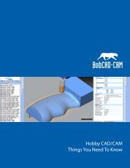
Introduction<br />
This tutorial covers how to create a machine. Machine creation starts with a machine definition to define each<br />
element of the machine. Then the parameters are defined for each element of the machine, such as the<br />
moving direction and limits. The machine parameter values are used in posting. For each element, geometry<br />
(.stl) files are added to define what appears in the simulation window.<br />
There are two levels of machine simulation: <strong>Standard</strong> Simulation and <strong>Pro</strong> Simulation. If you have purchased<br />
the 4 Axis <strong>Pro</strong>, 5 Axis <strong>Standard</strong>, or 5 Axis <strong>Pro</strong> module, then you have the <strong>Pro</strong> Simulation. Regardless of what<br />
level of machine simulation you have, you must still create a proper machine definition. The only difference is<br />
that with <strong>Standard</strong> Simulation, you can’t add geometry items to the machine definition that is used for<br />
simulation.<br />
The following image shows the 4-axis machine that is created in this example.<br />
19 Real CNC <strong>Pro</strong>gramming Solutions for Global manufacturing |Copyright (c) <strong>BobCAD</strong>-<strong>CAM</strong>, Inc. 2012
<strong>BobCAD</strong>-<strong>CAM</strong> Version 25 Getting Started Guide<br />
Machine Setup & Post <strong>Pro</strong>cessor Installation<br />
The following image shows all of the individual geometry files (.stl), together in one Workspace. This is shown<br />
to help you understand how each geometry item is aligned in the Workspace when creating the geometry files<br />
for the machine. The second image, the view is made transparent and zoomed in to show the coordinate<br />
system used to align the machine elements.<br />
20 Real CNC <strong>Pro</strong>gramming Solutions for Global manufacturing |Copyright (c) <strong>BobCAD</strong>-<strong>CAM</strong>, Inc. 2012
Part 1) Add a New Machine<br />
<strong>BobCAD</strong>-<strong>CAM</strong> Version 25 Getting Started Guide<br />
Machine Setup & Post <strong>Pro</strong>cessor Installation<br />
Step 1. In the <strong>CAM</strong> Tree, Click to expand the <strong>CAM</strong> Part folder. Right-Click <strong>Mill</strong>ing Tools, Click Default,<br />
and Click Current Settings.<br />
Step 2. On the left side of the <strong>Mill</strong>ing Settings dialog box, make sure that Machine Parameters is selected.<br />
Step 3. On the right side of the dialog box, in the Machine group, Click Add.<br />
21 Real CNC <strong>Pro</strong>gramming Solutions for Global manufacturing |Copyright (c) <strong>BobCAD</strong>-<strong>CAM</strong>, Inc. 2012
<strong>BobCAD</strong>-<strong>CAM</strong> Version 25 Getting Started Guide<br />
Machine Setup & Post <strong>Pro</strong>cessor Installation<br />
Step 4. In the Add/Modify dialog box, next to Machine Name, type the name of your machine. For this<br />
example, the name is 4 Axis Example.<br />
Step 5. Next to Axes, select the 4 Axis Machine. To close the dialog box and add the new machine, Click OK.<br />
Step 6. The Make list now shows the new machine is selected and the Number of Axes should display the<br />
number 4.<br />
Step 7. In the Machine Parameters group, define the parameters for your machine.<br />
22 Real CNC <strong>Pro</strong>gramming Solutions for Global manufacturing |Copyright (c) <strong>BobCAD</strong>-<strong>CAM</strong>, Inc. 2012
<strong>BobCAD</strong>-<strong>CAM</strong> Version 25 Getting Started Guide<br />
Machine Setup & Post <strong>Pro</strong>cessor Installation<br />
Part 2) Locating the Machine Definition Files<br />
Step 1. When you create a new machine, a folder is automatically created along with an XML file of the<br />
machine definition, in the <strong>BobCAD</strong>-<strong>CAM</strong> Data folder. The default location is: C:\<strong>BobCAD</strong>-<strong>CAM</strong><br />
Data\<strong>BobCAD</strong>-<strong>CAM</strong> V25\MachSim\Machine Name.... This is the same location in which the geometry<br />
files for the machine must be stored.<br />
Step 2. For the purposes of this tutorial, the next step is to copy the geometry files from the default machine<br />
that is provided by <strong>BobCAD</strong>-<strong>CAM</strong>.<br />
Step 3. Open the following folder: C:\<strong>BobCAD</strong>-<strong>CAM</strong> Data\<strong>BobCAD</strong>-<strong>CAM</strong> V25\MachSim. Notice the folder<br />
named 4 Axis Example has been automatically created. If you open the folder, you will see the 4 Axis<br />
Example.xml file that is created to save all of the machine information.<br />
23 Real CNC <strong>Pro</strong>gramming Solutions for Global manufacturing |Copyright (c) <strong>BobCAD</strong>-<strong>CAM</strong>, Inc. 2012
<strong>BobCAD</strong>-<strong>CAM</strong> Version 25 Getting Started Guide<br />
Machine Setup & Post <strong>Pro</strong>cessor Installation<br />
Step 4. Open the BC_4x_<strong>Mill</strong> folder, and select all of the files except the .xml file. Press CTRL+C to copy the<br />
selected files.<br />
24 Real CNC <strong>Pro</strong>gramming Solutions for Global manufacturing |Copyright (c) <strong>BobCAD</strong>-<strong>CAM</strong>, Inc. 2012
<strong>BobCAD</strong>-<strong>CAM</strong> Version 25 Getting Started Guide<br />
Machine Setup & Post <strong>Pro</strong>cessor Installation<br />
Step 5. Open the 4 Axis Example folder and press CTRL+V to paste the copied files into the folder. These files<br />
are now available to add to the Machine Definition.<br />
25 Real CNC <strong>Pro</strong>gramming Solutions for Global manufacturing |Copyright (c) <strong>BobCAD</strong>-<strong>CAM</strong>, Inc. 2012
<strong>BobCAD</strong>-<strong>CAM</strong> Version 25 Getting Started Guide<br />
Machine Setup & Post <strong>Pro</strong>cessor Installation<br />
Part 3) The Machine Definition Dialog Box - Define the Y-Axis Parameters<br />
Step 1. On the left side of the <strong>Mill</strong>ing Settings dialog box, Click Machine Definition.<br />
Step 2. Notice the Machine group in the middle of the dialog box. The machine tree shows all of the machine<br />
elements that have been automatically created. This definition includes the linear axes, the rotational<br />
axis, and the dynamic holder and workpiece elements.<br />
Step 3. The items in the tree are used to define or modify the parameters of each component. For example, in<br />
the tree, Click Y. Notice on the right, in the Machine Data group, the parameters for the Y-axis are<br />
displayed.<br />
Step 4. The Direction and the Limits for the Y-axis must be defined. By default the Y-axis Direction is defined<br />
by the vector X0Y1Z0. This defines the direction as the positive Y-axis. The machine being built requires<br />
the vector to be negative. Under Direction, next to Y, Click in the box, and change the value to -1. The<br />
Y-axis vector is now X0Y-1Z0.<br />
26 Real CNC <strong>Pro</strong>gramming Solutions for Global manufacturing |Copyright (c) <strong>BobCAD</strong>-<strong>CAM</strong>, Inc. 2012
<strong>BobCAD</strong>-<strong>CAM</strong> Version 25 Getting Started Guide<br />
Machine Setup & Post <strong>Pro</strong>cessor Installation<br />
Note: The vector direction for the axes is determined by the type of machine. For machines that the table<br />
(and not the head) moves in the X- and Y-axes, generally these values are negative. For machines<br />
where the head (tool) moves in the X- and Y-axes, generally these values are positive. The direction<br />
is determined by the relationship of the machine elements and which way they need to move to<br />
make the tool move in a positive direction in each of the X, Y, and Z axes.<br />
Step 5. Under Limits, to the right of Min, Click in the box, and type the distance that this machine element can<br />
move along the defined direction. For this example, type -10. This defines 10 inches of travel in the<br />
negative Y-axis direction.<br />
Step 6. To the right of Max value, Click in the box and define the maximum distance that the element can<br />
move along the defined direction. For this example, type 10. This defines 10 inches of travel in the<br />
positive Y-axis direction.<br />
Step 7. Set the Initial Value for this element to represent the elements starting position. For this example,<br />
type 0. This sets the initial position to the origin or zero location of the Y-axis.<br />
27 Real CNC <strong>Pro</strong>gramming Solutions for Global manufacturing |Copyright (c) <strong>BobCAD</strong>-<strong>CAM</strong>, Inc. 2012
Part 4) Define the X-Axis Parameters<br />
<strong>BobCAD</strong>-<strong>CAM</strong> Version 25 Getting Started Guide<br />
Machine Setup & Post <strong>Pro</strong>cessor Installation<br />
Step 1. In the Machine group, Click X to select the linear X-axis. In the Machine Data group, next to X, change<br />
the value to -1. Again, this defines that the X-axis elements must move in the negative X-axis direction<br />
in order to cause the tool to move in the positive direction in reference to the part.<br />
Step 2. Under Limits, next to Min, Click in the box, and type -29. This value defines 29 inches of travel in the<br />
negative X-axis direction.<br />
Step 3. Next to Max, Click in the box, and type 11.<br />
Step 4. Next to Initial Value, Click in the box, and type 0.<br />
28 Real CNC <strong>Pro</strong>gramming Solutions for Global manufacturing |Copyright (c) <strong>BobCAD</strong>-<strong>CAM</strong>, Inc. 2012
Part 5) Define the A-Axis Parameters<br />
<strong>BobCAD</strong>-<strong>CAM</strong> Version 25 Getting Started Guide<br />
Machine Setup & Post <strong>Pro</strong>cessor Installation<br />
Step 1. In the Machine group, Click A to select the rotary A-axis. In the Machine Data group, notice that the<br />
Direction is defined as X1Y0Z0. This defines rotation around the X-axis.<br />
Step 2. Notice that the Centerpoint is defined as X0Y0Z0. This defines the center point of rotation in reference<br />
to the machine zero. Because the geometry was aligned to the zero of the reference point, this<br />
distance is zero.<br />
Step 3. The next step is define the rotary limits. Under Limits, next to Min, Click in the box and type -100,000.<br />
You must set this value to the degrees of rotation supported by the machine.<br />
Step 4. Next to Max, Click in the box and type 100,000.<br />
Step 5. Next to Initial Value, Click in the box and type 0.<br />
29 Real CNC <strong>Pro</strong>gramming Solutions for Global manufacturing |Copyright (c) <strong>BobCAD</strong>-<strong>CAM</strong>, Inc. 2012
Part 6) Define the Z-Axis Parameters<br />
<strong>BobCAD</strong>-<strong>CAM</strong> Version 25 Getting Started Guide<br />
Machine Setup & Post <strong>Pro</strong>cessor Installation<br />
Step 1. In the Machine group, Click Z to select the linear X-axis. In the Machine Data group, notice that the<br />
Direction is defined as X0Y0Z1. This defines movement along the Z-axis.<br />
Step 2. Under Limits, next to Min, Click in the box and type -9.<br />
Step 3. Next to Max, Click in the box and type 25.<br />
Step 4. Next to Initial Value, Click in the box and type 18.<br />
30 Real CNC <strong>Pro</strong>gramming Solutions for Global manufacturing |Copyright (c) <strong>BobCAD</strong>-<strong>CAM</strong>, Inc. 2012
Part 7) Add the Machine Base<br />
<strong>BobCAD</strong>-<strong>CAM</strong> Version 25 Getting Started Guide<br />
Machine Setup & Post <strong>Pro</strong>cessor Installation<br />
When creating geometry, the files must be saved using the .stl file extension.<br />
Important: The <strong>Pro</strong> Simulation is included with the 4 Axis <strong>Pro</strong>, 5 Axis <strong>Standard</strong>, or 5 Axis <strong>Pro</strong> modules. If<br />
you do not have <strong>Pro</strong> Simulation, you can't add geometry as shown in the following steps.<br />
Step 1. In the Machine group, Right-Click the top tree item 4 Axis Example, and Click Add Geometry.<br />
31 Real CNC <strong>Pro</strong>gramming Solutions for Global manufacturing |Copyright (c) <strong>BobCAD</strong>-<strong>CAM</strong>, Inc. 2012
<strong>BobCAD</strong>-<strong>CAM</strong> Version 25 Getting Started Guide<br />
Machine Setup & Post <strong>Pro</strong>cessor Installation<br />
Step 2. In the Open dialog box, navigate to the 4 Axis Example folder, and select BC_4x_<strong>Mill</strong>_Rot-X_Base.stl,<br />
and Click Open.<br />
32 Real CNC <strong>Pro</strong>gramming Solutions for Global manufacturing |Copyright (c) <strong>BobCAD</strong>-<strong>CAM</strong>, Inc. 2012
<strong>BobCAD</strong>-<strong>CAM</strong> Version 25 Getting Started Guide<br />
Machine Setup & Post <strong>Pro</strong>cessor Installation<br />
Step 3. The geometry item is added to the tree. In the tree, Click geometry so it is selected. In the Machine<br />
Data group, next to ID, Click the name (geometry) and change the name to mh_Base. Because the<br />
prefix mh_ was added, the visibility of this item is changed using the machine housing view toggle (in<br />
the simulation window).<br />
Step 4. Notice that the parameters for the geometry item are displayed in the Machine Data group. The<br />
parameters for the added geometry can be modified from this location. For example, if you needed to<br />
change the .stl file, in the left column Click Geometry. Notice that the icon appears next to<br />
BC_4x_<strong>Mill</strong>_Rot-X_Base.stl. You can Click to display the Open dialog box and select a new geometry<br />
file.<br />
33 Real CNC <strong>Pro</strong>gramming Solutions for Global manufacturing |Copyright (c) <strong>BobCAD</strong>-<strong>CAM</strong>, Inc. 2012
Part 8) Add the Y-Axis Geometry<br />
<strong>BobCAD</strong>-<strong>CAM</strong> Version 25 Getting Started Guide<br />
Machine Setup & Post <strong>Pro</strong>cessor Installation<br />
Step 1. In the machine tree, Right-Click Y, and Click Add Geometry.<br />
Step 2. In the Open dialog box, select BC_4x_<strong>Mill</strong>_Rot-X_Y Axis Base, and Click Open.<br />
Step 3. The geometry item is added to the tree. In the Machine Data group, next to ID, select the name<br />
(geometry) and type Y Axis Base.<br />
Step 4. Click Color, and on the right, Click . In the Color dialog box, select a color for the element and Click<br />
OK. When you run simulation, the Y-axis base will be shown with the selected color.<br />
Step 5. In the machine tree, Right-Click Y, and Click Add Geometry.<br />
Step 6. In the Open dialog box, select BC_4x_<strong>Mill</strong>_Rot-X_X Axis Base, and Click Open.<br />
Step 7. The geometry item is added to the tree. In the Machine Data group, next to ID, select the name<br />
(geometry) and type X Axis Base.<br />
Step 8. Set the color used for the base.<br />
34 Real CNC <strong>Pro</strong>gramming Solutions for Global manufacturing |Copyright (c) <strong>BobCAD</strong>-<strong>CAM</strong>, Inc. 2012
Part 9) Add the X-Axis Geometry<br />
<strong>BobCAD</strong>-<strong>CAM</strong> Version 25 Getting Started Guide<br />
Machine Setup & Post <strong>Pro</strong>cessor Installation<br />
Step 1. In the machine tree, Right-Click X, and Click Add Geometry.<br />
Step 2. In the Open dialog box, select BC_4x_<strong>Mill</strong>_Rot-X_Table, and Click Open.<br />
Step 3. The geometry item is added to the tree. In the Machine Data group, next to ID, select the name<br />
(geometry) and type Table.<br />
Step 4. Set the color for the element.<br />
Step 5. Click Reflect Map, and on the right side, Click . In the Open dialog box, select the<br />
TableReflection.bmp file and Click OK. Image files used for the Reflect Map must use the .bmp file<br />
extension.<br />
Step 6. In the machine tree, Right-Click X, and Click Add Geometry.<br />
Step 7. In the Open dialog box, select BC_4x_<strong>Mill</strong>_Rot-X_Rotary_Base, and Click Open.<br />
Step 8. The geometry item is added to the tree. In the Machine Data group, next to ID, select the name<br />
(geometry) and type Rotary Base.<br />
Step 9. Set the color for the X-axis base.<br />
35 Real CNC <strong>Pro</strong>gramming Solutions for Global manufacturing |Copyright (c) <strong>BobCAD</strong>-<strong>CAM</strong>, Inc. 2012
Part 10) Add the A-Axis Geometry<br />
<strong>BobCAD</strong>-<strong>CAM</strong> Version 25 Getting Started Guide<br />
Machine Setup & Post <strong>Pro</strong>cessor Installation<br />
Step 1. In the machine tree, Right-Click A, and Click Add Geometry.<br />
Step 2. In the Open dialog box, select BC_4x_<strong>Mill</strong>_Rot-X_Rotary_Face, and Click Open.<br />
Step 3. The geometry item is added to the tree. In the Machine Data group, next to ID, select the name<br />
(geometry) and type Rotary Table.<br />
Step 4. Set the color for the element.<br />
36 Real CNC <strong>Pro</strong>gramming Solutions for Global manufacturing |Copyright (c) <strong>BobCAD</strong>-<strong>CAM</strong>, Inc. 2012
Part 11) Add the Z-Axis Geometry<br />
<strong>BobCAD</strong>-<strong>CAM</strong> Version 25 Getting Started Guide<br />
Machine Setup & Post <strong>Pro</strong>cessor Installation<br />
Step 1. In the machine tree, Right-Click Z, and Click Add Geometry.<br />
Step 2. In the Open dialog box, select BC_4x_<strong>Mill</strong>_Rot-X_Z Axis Spindle and Click Open.<br />
Step 3. The geometry item is added to the tree. In the Machine Data group, next to ID, select the name<br />
(geometry) and type Spindle.<br />
37 Real CNC <strong>Pro</strong>gramming Solutions for Global manufacturing |Copyright (c) <strong>BobCAD</strong>-<strong>CAM</strong>, Inc. 2012
<strong>BobCAD</strong>-<strong>CAM</strong> Version 25 Getting Started Guide<br />
Machine Setup & Post <strong>Pro</strong>cessor Installation<br />
Part 12) About the Dynamic Elements<br />
The dynamic elements are the elements that can change with each program. The Workpiece Transform<br />
contains the first set of dynamic elements in the tree. This transform includes the toolpath, stock, fixture, and<br />
the workpiece. You do not have to define geometry for each of these items because they are defined by each<br />
program that you create. This is also true for the Holder Transform elements. These dynamic elements are<br />
automatically created for you when you create a new machine.<br />
Step 1. In the Machine group, under the Workpiece Transform, Click Initialstock. Notice the parameters in the<br />
Machine Data group. As with the other geometry items, you can define a color for the element. It is<br />
helpful to define a different color for each element that appears in simulation.<br />
38 Real CNC <strong>Pro</strong>gramming Solutions for Global manufacturing |Copyright (c) <strong>BobCAD</strong>-<strong>CAM</strong>, Inc. 2012
<strong>BobCAD</strong>-<strong>CAM</strong> Version 25 Getting Started Guide<br />
Machine Setup & Post <strong>Pro</strong>cessor Installation<br />
Step 2. In the Machine Data group, next to Transparency, Click in the box and change the value to 40. This<br />
makes the initial stock item that is shown in simulation appear with forty-percent transparency. When<br />
this item is fully visible, it will still appear slightly transparent which makes it easier to tell it apart from<br />
the stock or workpiece items.<br />
39 Real CNC <strong>Pro</strong>gramming Solutions for Global manufacturing |Copyright (c) <strong>BobCAD</strong>-<strong>CAM</strong>, Inc. 2012
<strong>BobCAD</strong>-<strong>CAM</strong> Version 25 Getting Started Guide<br />
Machine Setup & Post <strong>Pro</strong>cessor Installation<br />
Step 3. In the Machine group, under the Workpiece Transform, Click Stock.<br />
40 Real CNC <strong>Pro</strong>gramming Solutions for Global manufacturing |Copyright (c) <strong>BobCAD</strong>-<strong>CAM</strong>, Inc. 2012
<strong>BobCAD</strong>-<strong>CAM</strong> Version 25 Getting Started Guide<br />
Machine Setup & Post <strong>Pro</strong>cessor Installation<br />
Step 4. In the Machine Data group, notice the name in the Geometry row. For each program that you create,<br />
when you simulate, the stock.stl (and the workpiece.stl) files are automatically created and placed in<br />
the machine's folder with the other geometry files (as shown earlier in this example). These files are<br />
created using the defined stock and the selected geometry for the program.<br />
41 Real CNC <strong>Pro</strong>gramming Solutions for Global manufacturing |Copyright (c) <strong>BobCAD</strong>-<strong>CAM</strong>, Inc. 2012
<strong>BobCAD</strong>-<strong>CAM</strong> Version 25 Getting Started Guide<br />
Machine Setup & Post <strong>Pro</strong>cessor Installation<br />
Step 5. In the Machine group, under the Holder Transform, Click Tool. Notice the parameter displayed in the<br />
Machine Data group. You can change the color for each part of the tool and tool holder, as well as the<br />
transparency and reflectivity.<br />
42 Real CNC <strong>Pro</strong>gramming Solutions for Global manufacturing |Copyright (c) <strong>BobCAD</strong>-<strong>CAM</strong>, Inc. 2012
Part 13) About the Collision Check<br />
<strong>BobCAD</strong>-<strong>CAM</strong> Version 25 Getting Started Guide<br />
Machine Setup & Post <strong>Pro</strong>cessor Installation<br />
At the bottom of the Machine tree, there should be an item labeled CC. This is the collision check that is<br />
automatically added to the tree when you created the new machine. This item defines the dynamic elements<br />
that are included in the collision check.<br />
Step 1. To add a collision check to the tree, Right-Click the top tree item 4 Axis Example, Click Add CollCheck,<br />
and Click Tool-Workpiece. This adds a collision check to the tree that is automatically set between the<br />
workpiece and the tool.<br />
Step 2. In the Machine group, Click the new collision check item (CC1). Notice the information in the Machine<br />
Data group. There are three boxes displayed. The larger box on the left side contains all of the items<br />
that are available to add to a collision check group. The two boxes on the right, Group 1 and Group 2,<br />
define the items that are collision checked. Any items in Group 1 are collision checked with the items in<br />
Group 2. The Workpiece-Tool collision check that was added automatically places the Workpiece in<br />
Group 1 and the Tool is placed in Group 2.<br />
43 Real CNC <strong>Pro</strong>gramming Solutions for Global manufacturing |Copyright (c) <strong>BobCAD</strong>-<strong>CAM</strong>, Inc. 2012
<strong>BobCAD</strong>-<strong>CAM</strong> Version 25 Getting Started Guide<br />
Machine Setup & Post <strong>Pro</strong>cessor Installation<br />
Step 3. To add an item to a collision check group, in the list on the left side, Click the item to add. Next to the<br />
Group box to which the item is added, Click .<br />
Step 4. To remove an item from a collision check, Click the item to remove, and then next to the Group box,<br />
Click .<br />
Step 5. If you add a User Defined collision check, no items are automatically added to the Group 1 and Group<br />
2 boxes.<br />
Step 6. To finish the machine creation and save the information, at the bottom of the <strong>Mill</strong>ing Settings dialog<br />
box, Click OK.<br />
44 Real CNC <strong>Pro</strong>gramming Solutions for Global manufacturing |Copyright (c) <strong>BobCAD</strong>-<strong>CAM</strong>, Inc. 2012
<strong>BobCAD</strong>-<strong>CAM</strong> Version 25 Getting Started Guide<br />
Machine Setup & Post <strong>Pro</strong>cessor Installation<br />
Part 14) Additional Machine Parameters<br />
After your machine has been created, you also need to define the Posting parameters for the machine. To<br />
learn about the remaining options in the <strong>Mill</strong>ing Settings dialog box, view the <strong>Mill</strong>ing Settings Default dialog<br />
box help topic.<br />
This concludes the tutorial.<br />
45 Real CNC <strong>Pro</strong>gramming Solutions for Global manufacturing |Copyright (c) <strong>BobCAD</strong>-<strong>CAM</strong>, Inc. 2012
<strong>BobCAD</strong>-<strong>CAM</strong> Version 25 Getting Started Guide<br />
Machine Setup Checklist<br />
MACHINE SETUP CHECKLIST<br />
In order to configure your machine there is some information you will first need to gather. The check list<br />
below will help you gather this information.<br />
Machine Name: _________________________________________________<br />
This is the name of the machine.<br />
Controller Make and Model: ___________________________________<br />
This is the model of the machine and make of the controller.<br />
Type of Machine: __________________________________________<br />
This is the type of 4 th / 5 th axis machine.<br />
Example:<br />
4 th Axis Vertical <strong>Mill</strong><br />
4 th Axis Horizontal <strong>Mill</strong><br />
Table – Table<br />
Head – Head<br />
Head – Table<br />
Head – Head Nutating<br />
ETC...<br />
46 Real CNC <strong>Pro</strong>gramming Solutions for Global manufacturing |Copyright (c) <strong>BobCAD</strong>-<strong>CAM</strong>, Inc. 2012
<strong>BobCAD</strong>-<strong>CAM</strong> Version 25 Getting Started Guide<br />
Machine Setup Checklist<br />
Maximum Spindle Speed: _____________________________________<br />
Fastest speed (RPM) the spindle can rotate.<br />
Maximum Feed Rate: __________________________________________<br />
Fastest allowable feed rate (IPM) the machine can travel.<br />
NC File Extension: __________________________________________<br />
This is the file extension that the machine requires to load the NC program into the controller.<br />
47 Real CNC <strong>Pro</strong>gramming Solutions for Global manufacturing |Copyright (c) <strong>BobCAD</strong>-<strong>CAM</strong>, Inc. 2012
<strong>BobCAD</strong>-<strong>CAM</strong> Version 25 Getting Started Guide<br />
Machine Setup Checklist<br />
Direction Vector:<br />
Most machines follow what is known as the “Right Hand Rule” when it comes to directions of motion when<br />
using the Cartesian coordinate system. We will use the standard “Right Hand Rule” as our base when<br />
comparing your machines movement to complete the following questions. Please keep in mind that all of the<br />
following questions refer to the direction the TOOL moves in the workpiece.<br />
X axis Direction:<br />
When you jog your machine in the positive direction does the tool move to the Right?<br />
Yes__ / No__<br />
(Yes = Tool Motion Matches Right Hand Rule)<br />
Y axis Direction:<br />
When you jog your machine in the positive direction does the tool move to the Back?<br />
Yes__ / No__<br />
(Yes = Tool Motion Matches Right Hand Rule)<br />
Z axis Direction:<br />
When you jog your machine in the positive direction does the tool move Up?<br />
Yes__ / No___<br />
(Yes = Tool Motion Matches Right Hand Rule)<br />
48 Real CNC <strong>Pro</strong>gramming Solutions for Global manufacturing |Copyright (c) <strong>BobCAD</strong>-<strong>CAM</strong>, Inc. 2012
<strong>BobCAD</strong>-<strong>CAM</strong> Version 25 Getting Started Guide<br />
Machine Setup Checklist<br />
Minimum & Maximum Values for Axis Travel:<br />
X____ _____<br />
Y____ _____<br />
Z____ _____<br />
The minimum and maximum absolute coordinates for each axis. These values are from the rotation zero. This<br />
zero is a virtual machine zero used by <strong>BobCAD</strong> and is not necessarily the machine home.<br />
**To pull the values for the limits of the machine**<br />
These measurements are done with the machine spindle empty.<br />
X-Axis:<br />
Line the center of the spindle up with the edge of the face of the indexer or the center of the platter and set as<br />
zero. Now move the machine to the max positive then the max negative amount in X. Record these numbers<br />
above.<br />
Y-Axis:<br />
Line the center of the spindle up with the center of rotation and set as zero. Now move the machine to the<br />
max positive then the max negative amount in Y. Record these numbers above.<br />
Z-Axis:<br />
The <strong>BobCAD</strong> machine zero for Z is the face of the spindle down at the center of the rotation axis. Move the<br />
machine to this position and set zero. Now move the machine to the max positive then the max negative<br />
amount in Z. Record numbers above. If the machine cannot get there, take as far down as it can and measure<br />
from center of rotation to spindle face. This does not have to be exact. However you want it as close as you<br />
can get it. If needed can use ruler. Now you can measure the Max positive movement in Z.<br />
For instance the spindle can only come down to 3” above rotation center.<br />
The max travel for Z is 15”. Then record above Max Z = 15” and minimum Z= +3”<br />
49 Real CNC <strong>Pro</strong>gramming Solutions for Global manufacturing |Copyright (c) <strong>BobCAD</strong>-<strong>CAM</strong>, Inc. 2012
<strong>BobCAD</strong>-<strong>CAM</strong> Version 25 Getting Started Guide<br />
Machine Setup Checklist<br />
Rotary Axes:<br />
The rotary axes of your machine need to be correctly defined for the internal mathematics of our post<br />
processing engine to function correctly. Again here we will reference the “Right Hand Rule” for defining your<br />
rotary axis components and we will also define the prefix used in the G-Code to operate them.<br />
Like the X Y Z axes the rotary axes of a machine tool can be referenced using the standards of the Right Hand<br />
Rule. The following image illustrates this as well as the following description. Please note the following axis<br />
identification is not the prefix used in the G-Code but how we identify the rotary axis components for building<br />
your machine. The prefix for each axis is defined in the next section.<br />
A axis – This is a rotary axis that rotates around the X axis of the machine.<br />
B axis – This is a rotary axis that rotates around the Y axis of the machine.<br />
C axis – This is a rotary axis that rotates around the Z axis of the machine.<br />
1st Rotary Axis – Using the above image what is your 1st rotary axis? __A__B__C__<br />
2nd Rotary Axis – Using the above image what is your 2nd rotary axis? __A__B__C__<br />
50 Real CNC <strong>Pro</strong>gramming Solutions for Global manufacturing |Copyright (c) <strong>BobCAD</strong>-<strong>CAM</strong>, Inc. 2012
<strong>BobCAD</strong>-<strong>CAM</strong> Version 25 Getting Started Guide<br />
Machine Setup Checklist<br />
Direction of Positive rotation on rotary:<br />
When facing the machine place a mark on the axis being rotated. Whether it is marker or tape and rotate the<br />
rotary axis positive. When following the Right Hand Rule standard axis rotation is counterclockwise when<br />
looking at the axis from the positive direction.<br />
1st Rotary Rotation:<br />
When you rotate the 1st axis positive does your machine rotate toward you in the positive direction?<br />
Yes__ / No__<br />
(Yes = Tool Motion Matches Right Hand Rule)<br />
2nd Rotary Rotation:<br />
When you rotate the 2nd axis positive does your machine rotate toward you in the positive direction?<br />
Yes__ / No__<br />
(Yes = Tool Motion Matches Right Hand Rule)<br />
51 Real CNC <strong>Pro</strong>gramming Solutions for Global manufacturing |Copyright (c) <strong>BobCAD</strong>-<strong>CAM</strong>, Inc. 2012
<strong>BobCAD</strong>-<strong>CAM</strong> Version 25 Getting Started Guide<br />
Machine Setup Checklist<br />
Rotary Centers:<br />
1st Rotary Axis: ____ ____ ____<br />
2nd Rotary Axis: ____ ____ ____<br />
X, Y, and Z center of rotation point for each rotary axis.<br />
Click Here for information on How to find the Rotation for the rotary axis.<br />
<strong>BobCAD</strong> Machine Zero to Center Of Rotation:<br />
This is a measurement from where we are going to define zero for our system’s calculations. This location is<br />
NOT where you have to define your work offset locations. The values for this option will vary based on<br />
machine configuration. All values are measured with the 4th & 5th axis of your machine at Zero location.<br />
Table/Table – For this machine type the values are measured from the center of the rotary platter at the face<br />
of the rotary platter going to the center of rotation for the 4th & 5th axis unit.<br />
Head/Head – For this machine type the values are measured from the face of the spindle to the center of<br />
rotation for the 4th & 5th axis.<br />
Head/Table – For this machine type the values are measured in one axis from the face of the spindle to the<br />
center of the rotating axis which tilts the spindle. The second rotation center will be aligned with the spindle<br />
face so a value of zero should suffice, but values are available here if necessary.<br />
52 Real CNC <strong>Pro</strong>gramming Solutions for Global manufacturing |Copyright (c) <strong>BobCAD</strong>-<strong>CAM</strong>, Inc. 2012
<strong>BobCAD</strong>-<strong>CAM</strong> Version 25 Getting Started Guide<br />
Machine Setup Checklist<br />
Rotary Axis G-Code Prefix:<br />
1st Rotary Axis: _________ Example: “A”<br />
2nd Rotary Axis: _________ Example: “B”<br />
What is the prefix (letter) used to identify your rotary axes?<br />
Minimum & Maximum Rotary Degrees:<br />
1st Rotary Axis: ______ ______<br />
2nd Rotary Axis: ______ ______<br />
What is the minimum (- direction) and maximum (+ direction) travel limits for each of your rotary axes?<br />
Rotary Axis limits:<br />
What is the limit of rotation for the rotary axis I.E. +9999.999 and<br />
-9999.999 or is there another limit? Or is it unlimited. Distance before it has to stop and rewind.<br />
53 Real CNC <strong>Pro</strong>gramming Solutions for Global manufacturing |Copyright (c) <strong>BobCAD</strong>-<strong>CAM</strong>, Inc. 2012
STL Files (Optional)<br />
<strong>BobCAD</strong>-<strong>CAM</strong> Version 25 Getting Started Guide<br />
Machine Setup Checklist<br />
STL Drawing files of each part of the machine. These are not required but helpful and can only be added for<br />
use with the full machine simulation. The full machine simulation is included with- 4 Axis <strong>Pro</strong>, 5 Axis <strong>Standard</strong><br />
and 5 Axis <strong>Pro</strong>.<br />
Machine Base – _________________________________________________<br />
X-AXIS – _________________________________________________<br />
Y-AXIS – _________________________________________________<br />
Z-AXIS – _________________________________________________<br />
1st Rotary Axis – _________________________________________________<br />
2nd Rotary Axis – _________________________________________________<br />
More or less files can be used; this varies by the amount of detail desired and machine type.<br />
54 Real CNC <strong>Pro</strong>gramming Solutions for Global manufacturing |Copyright (c) <strong>BobCAD</strong>-<strong>CAM</strong>, Inc. 2012
Adding your machine<br />
<strong>BobCAD</strong>-<strong>CAM</strong> Version 25 Getting Started Guide<br />
Machine Setup Checklist<br />
Step 1. Gather all data from the Machine Setup Check-list.<br />
Step 2. Launch the <strong>BobCAD</strong>-<strong>CAM</strong> software.<br />
Step 3. Expand <strong>CAM</strong> Part.<br />
Step 4. Right-Click <strong>Mill</strong>ing Tools and Select Default > Current Settings.<br />
55 Real CNC <strong>Pro</strong>gramming Solutions for Global manufacturing |Copyright (c) <strong>BobCAD</strong>-<strong>CAM</strong>, Inc. 2012
<strong>BobCAD</strong>-<strong>CAM</strong> Version 25 Getting Started Guide<br />
Machine Setup Checklist<br />
Step 5. From the Machine Parameters select add.<br />
56 Real CNC <strong>Pro</strong>gramming Solutions for Global manufacturing |Copyright (c) <strong>BobCAD</strong>-<strong>CAM</strong>, Inc. 2012
<strong>BobCAD</strong>-<strong>CAM</strong> Version 25 Getting Started Guide<br />
Machine Setup Checklist<br />
Step 6. Enter the Name of your machine.<br />
Step 7. Choose the number of axes and type for your machine, Click OK.<br />
Note: For 2 axis machines select 3 Axis Machine the z values will be removed by the post-processor.<br />
57 Real CNC <strong>Pro</strong>gramming Solutions for Global manufacturing |Copyright (c) <strong>BobCAD</strong>-<strong>CAM</strong>, Inc. 2012
<strong>BobCAD</strong>-<strong>CAM</strong> Version 25 Getting Started Guide<br />
Machine Setup Checklist<br />
Step 8. In machine parameters enter the data for the rest of the parameters listed.<br />
<br />
<br />
<br />
<br />
Maximum # of Tools - sets the number of tools the machine can use for one program.<br />
Tool Change Position - this setting is not currently in use.<br />
Maximum Spindle Speed - sets the maximum speed rate for the spindle.<br />
Maximum Cutting Feedrate - sets the maximum feed-rate for cutting.<br />
58 Real CNC <strong>Pro</strong>gramming Solutions for Global manufacturing |Copyright (c) <strong>BobCAD</strong>-<strong>CAM</strong>, Inc. 2012
<strong>BobCAD</strong>-<strong>CAM</strong> Version 25 Getting Started Guide<br />
Machine Setup Checklist<br />
Step 9. Select machine definition under machine.<br />
59 Real CNC <strong>Pro</strong>gramming Solutions for Global manufacturing |Copyright (c) <strong>BobCAD</strong>-<strong>CAM</strong>, Inc. 2012
<strong>BobCAD</strong>-<strong>CAM</strong> Version 25 Getting Started Guide<br />
Machine Setup Checklist<br />
Step 10. Click on each axis label under your new machine; enter the Direction vector, Limits, Initial value and<br />
Center Point.<br />
<br />
<br />
<br />
ID – The axis name<br />
Direction - This determines the direction an axis travels.<br />
Limits - The limit or minimum & maximum absolute position for the axis.<br />
60 Real CNC <strong>Pro</strong>gramming Solutions for Global manufacturing |Copyright (c) <strong>BobCAD</strong>-<strong>CAM</strong>, Inc. 2012
<strong>BobCAD</strong>-<strong>CAM</strong> Version 25 Getting Started Guide<br />
Machine Setup Checklist<br />
Step 11. Select Posting and then select the post-processor to use with this machine, and then choose the<br />
other options desired.<br />
61 Real CNC <strong>Pro</strong>gramming Solutions for Global manufacturing |Copyright (c) <strong>BobCAD</strong>-<strong>CAM</strong>, Inc. 2012
<strong>BobCAD</strong>-<strong>CAM</strong> Version 25 Getting Started Guide<br />
Posting<br />
POSTING<br />
Post <strong>Pro</strong>cessor<br />
<br />
Select - displays the Open dialog box for you to locate and select a (.<strong>Mill</strong>Pst) post processor to use for the<br />
selected machine.<br />
Tool Pattern<br />
<br />
Select - displays the Open dialog box for you to select a tool pattern file (.tpatt) that is used for to save the<br />
tool pattern information for milling.<br />
NC File Path<br />
<br />
<br />
Select - displays the Browse For Folder dialog box for you to locate or create a folder in which the posted<br />
NC program is stored.<br />
NC File Extension - allows you to specify a file extension that is automatically added to the NC program<br />
file.<br />
<strong>Pro</strong>gram<br />
<br />
Number - is the program number as it appears in the posted NC program.<br />
Absolute/Incremental<br />
<br />
<br />
<br />
Post Setting - uses the post processor settings to define absolute or incremental posting values.<br />
Absolute - uses absolute values only for posting.<br />
Incremental - uses incremental values only for posting.<br />
Sequence Numbers<br />
<br />
<br />
Start Number - designates the starting line number for events in the NC program if the machine is<br />
configured to output them.<br />
Sequence # Increment - sets the number added to each subsequent line number for the next line.<br />
62 Real CNC <strong>Pro</strong>gramming Solutions for Global manufacturing |Copyright (c) <strong>BobCAD</strong>-<strong>CAM</strong>, Inc. 2012
Subprogram Numbers<br />
<strong>BobCAD</strong>-<strong>CAM</strong> Version 25 Getting Started Guide<br />
Posting<br />
<br />
Output Subprograms<br />
Selected - Select this check box to generate repetitive subprograms in the posted NC program, if the<br />
post processor is set up to do so.<br />
Cleared - Clear this check box when not generating subprograms.<br />
The following two options are only available when the Output Subprograms check box is selected.<br />
<br />
<br />
Subprogram Start # - sets the first subprogram number used in the NC program.<br />
Subprogram # Increment - if more than one subprogram is generated, this value sets the number added to<br />
the previous subprogram number for the next.<br />
Output Arcs in 4-Axis NC <strong>Pro</strong>gram<br />
<br />
GCode 4 Axis Arcs OK<br />
Selected - Select this check box to output arcs in the NC program for 4-axis machining.<br />
Cleared - Clear this check box to output only points and line segments in the NC program for 4-axis<br />
machining.<br />
63 Real CNC <strong>Pro</strong>gramming Solutions for Global manufacturing |Copyright (c) <strong>BobCAD</strong>-<strong>CAM</strong>, Inc. 2012
<strong>BobCAD</strong>-<strong>CAM</strong> Version 25 Getting Started Guide<br />
Posting<br />
Step 12. If you are using 4 or 5 axis pro then select Multi-Axis Posting then select the options desired.<br />
64 Real CNC <strong>Pro</strong>gramming Solutions for Global manufacturing |Copyright (c) <strong>BobCAD</strong>-<strong>CAM</strong>, Inc. 2012
<strong>BobCAD</strong>-<strong>CAM</strong> Version 25 Getting Started Guide<br />
Multi-Axis Posting<br />
MULTI-AXIS POSTING<br />
Angle Pair<br />
For many 5-axis machines there are two possible solutions to any point in a toolpath. The solution here refers<br />
to the angles used for each rotational axis. The following images show a part with the two possible Angle Pair<br />
solutions (this is the tool orientation for the toolpath starting point). The tool orientation to the part is the<br />
same in each situation; however, the table is rotated 180 degrees. The Angle Pair options control which<br />
solution is used. The purpose of the Auto Angle Pair is to use the solution that creates the least amount of<br />
tool-axis orientation change from the previous toolpath position. Keep in mind that some machine can't use<br />
both pairs based on rotational limits.<br />
First Solution<br />
Other Solution<br />
<br />
<br />
Auto Angle Pair<br />
Selected - Select this check box to make the Start Angle Type options available.<br />
Cleared - Clear this check box to make the Other Angle Pair check box available.<br />
Other Angle Pair<br />
Selected - Select this check box to use the Other Angle solution.<br />
Cleared - Clear this check box to not use the Other Angle solution.<br />
65 Real CNC <strong>Pro</strong>gramming Solutions for Global manufacturing |Copyright (c) <strong>BobCAD</strong>-<strong>CAM</strong>, Inc. 2012
<strong>BobCAD</strong>-<strong>CAM</strong> Version 25 Getting Started Guide<br />
Multi-Axis Posting<br />
<br />
Start Angle Type<br />
<br />
Select Between Two Solutions - allows the software to select between two possible solutions.<br />
<br />
Use - allows you to select one of the two following options.<br />
First Solution - is the solution that results in the least amount of axis orientation change from<br />
the toolpath start point or the previous toolpath orientation.<br />
<br />
Other Solution - is the solution opposite to the First Solution.<br />
Instead of using Select Between Two Solutions, you can provide a preferred First- and Second-Axis<br />
Rotation Angle, the software selects the solution closest to that value. Positive and Negative values can be<br />
used and the solution that is closest to the <strong>Pro</strong>vided Rotation Angle is used. For example, if you set the<br />
First Rotation Angle to 80 degrees, and the two possible solutions are: C = 90 degrees or C = -90 degrees,<br />
the post uses C = 90 degrees.<br />
<br />
<br />
<strong>Pro</strong>vide First Rotation Angle - allows you to type a preferred starting angle for the first rotational axis<br />
in the Rotation Angle Value box.<br />
<strong>Pro</strong>vide Second Rotation Angle - allows you to type a preferred starting angle for the second rotational<br />
axis in the Rotation Angle Value box.<br />
Rotation Angle Value - type the preferred starting angle for the First or Second Rotation Angle.<br />
Machine Limits<br />
The Machine Limits are used to confirm that the machine limits are not exceeded. When a program exceeds<br />
the set limits, it does not post. To set the Machine Limits, select a limit group from the Limits box and then<br />
type values for the following two parameters.<br />
<br />
<br />
<br />
Angle Tolerance For Using Machine Limits - type a value from which the selected Machine Limits can vary.<br />
If you set Machine Limits for an axis between 0 and 90 degrees, and set an Angle Tolerance of 2, then the<br />
possible range becomes -2 to 92 degrees.<br />
Angle Change Limit - type a value in degrees to limit the amount of angle change from one toolpath<br />
position to the next. If an angle change exceeds this limit, then a retract move is applied in the post.<br />
Limits box - select one of the following options to be affected by the Angle Tolerance and Angle Change<br />
Limit parameters:<br />
No Limits<br />
Translational Limits<br />
Rotational Limits<br />
All Limits<br />
66 Real CNC <strong>Pro</strong>gramming Solutions for Global manufacturing |Copyright (c) <strong>BobCAD</strong>-<strong>CAM</strong>, Inc. 2012
<strong>BobCAD</strong>-<strong>CAM</strong> Version 25 Getting Started Guide<br />
Multi-Axis Posting<br />
Pole Handling<br />
When a five axis machine is used to run a 3-axis toolpath, there are certain situations that make the C-axis<br />
value arbitrary. What this means is that by changing the X- and Y-axis values appropriately, any C-axis value<br />
used creates the same results. For example, when a cylinder is located in the center of the table, depending on<br />
the machine, there are multiple ways to cut the profile of the cylinder. The rotation axis can be fixed while the<br />
linear axes are used to cut the part. On the other hand, the linear movements can be fixed, while the table is<br />
allowed to rotate in order to cut the part. This situation where the C-value is arbitrary, because the spindle<br />
direction and the table direction are collinear, is called a singularity or pole. The Pole Handling options are<br />
used to control these situations as follows.<br />
Freeze Angle Around Pole - fixes the rotational axis in order to use the linear axes movements.<br />
<br />
<br />
<br />
<br />
<br />
Use Rotation Angle Around Pole to Stay Within Linear Axis Limits - is used when a program exceeds the<br />
linear axis limitations. The extents of the linear movements are fixed in order to use the rotational axis as a<br />
substitute for the linear movement limitations.<br />
Linear Interpolation of Rotation Angle Around Pole - calculates rotational axis values to make the changes<br />
from one value to the next in a linear fashion. The linear distribution is based on the tool tip position from<br />
one toolpath point to the next. This is useful when a 3-axis toolpath is converted to a 5-axis toolpath. For<br />
example, when a toolpath transitions from linear motions to rotational motions (from 3-axis to 5-axis), an<br />
abrupt change can result because of the conversion. This option is used to avoid these abrupt changes by<br />
setting a constant (linear) rate of change for the rotational axis.<br />
Smooth Interpolation of Rotation Angle Around Pole - similar to Linear Interpolation, this option also<br />
manipulates the table rotation speed to create a more fluent transition.<br />
Force Table Rotation - uses table rotation moves instead of linear moves when a multi-axis toolpath<br />
approaches 3-axis positioning.<br />
Pole Angle Tolerance - controls the angle between the tool axis orientation and the pole or main spindle<br />
direction (for example the Z-axis). It controls how far the tool can tilt from the pole and still be considered<br />
parallel, in order to be used as a pole.<br />
Tool Repositioning<br />
In certain scenarios, when machine limits are reached, a retract move is needed. Tool Repositioning affects<br />
the retract move.<br />
Tool Retract - type a value for the tool retract distance when the Retract Tool to Maximum check box is<br />
cleared.<br />
Retract Tool To Maximum<br />
Selected - Select this check box to retract the tool to the maximum distance set for the machine.<br />
Cleared - Clear this check box to type a retract distance in the Tool Retract box.<br />
67 Real CNC <strong>Pro</strong>gramming Solutions for Global manufacturing |Copyright (c) <strong>BobCAD</strong>-<strong>CAM</strong>, Inc. 2012
Point Interpolation<br />
<strong>BobCAD</strong>-<strong>CAM</strong> Version 25 Getting Started Guide<br />
Multi-Axis Posting<br />
<br />
Interpolation Type - select one of the two following options.<br />
By Vectors - creates the interpolation between the two endpoints of a toolpath segment in the<br />
shortest possible way. The movement happens in a flat plane.<br />
By Machine Angles - creates the interpolation between the two endpoints of a toolpath segment<br />
gradually with respect to the machine kinematics. The movement does not necessarily happen in a flat<br />
plane.<br />
Feed Move<br />
<br />
<br />
Max Distance<br />
Selected - Select this check box to type a maximum distance value for feed moves for the selected<br />
interpolation type.<br />
Cleared - Clear this check box to disable the Max Distance box.<br />
Max Angle<br />
Selected - Select this check box to type a maximum angle value for feed moves for the selected<br />
interpolation type.<br />
Cleared - Clear this check box to disable the Max Angle box.<br />
Rapid Move<br />
<br />
<br />
Max Distance<br />
Selected - Select this check box to type a maximum distance value for rapid moves for the selected<br />
interpolation type.<br />
Cleared - Clear this check box to disable the Max Distance box.<br />
Max Angle<br />
Selected - Select this check box to type a maximum angle value for rapid moves for the selected<br />
interpolation type.<br />
Cleared - Clear this check box to disable the Max Angle box.<br />
68 Real CNC <strong>Pro</strong>gramming Solutions for Global manufacturing |Copyright (c) <strong>BobCAD</strong>-<strong>CAM</strong>, Inc. 2012
Machine Definition Zero<br />
<strong>BobCAD</strong>-<strong>CAM</strong> Version 25 Getting Started Guide<br />
Multi-Axis Posting<br />
<br />
<br />
Real Machine Zero - the posted NC program uses the actual machine zero location.<br />
Work Offset Position - the posted NC program uses the location defined by the work offset.<br />
Move List Writer<br />
The Move List Writer options control what appears in the posted NC program. These options are used to set<br />
machine limits that are not exceeded in the posted NC program. Some machines don't have rotational limits,<br />
and some don't except large angle values. You can limit the angle values used.<br />
<br />
<br />
<br />
First Rotation Axis Angle Limit - limits the values used for the first rotational axis. Select: No Limits, Limit<br />
Between 0 and 360 degrees, or Limit Between -180 and 180 degrees.<br />
Second Rotation Axis Angle Limit - limits the values used for the second rotational axis. Select: No Limits,<br />
Limit Between 0 and 360 degrees, or Limit Between -180 and 180 degrees.<br />
Move List Coordinates - controls how the coordinates are output in the posted NC program.<br />
No Machine Compensation - outputs the moves in machine coordinates. No compensation is handled<br />
by the machine controller.<br />
Machine Compensation in Z Only - outputs all moves based off of the absolute machine zero point<br />
with Tool Length Compensation in Z only. This mode is commonly used with G43 Tool Height<br />
compensation at the controller.<br />
Machine Hybrid Compensation (Mixed Mode) - outputs all moves based off of the absolute machine<br />
zero point with Tool Length compensation along the tool axis.<br />
Part Based (Common for TCP) - outputs all moves based off of the workpiece-zero point or machine<br />
setup origin. This mode is commonly used with machine controllers that support TCP (Tool Center<br />
Point Compensation).<br />
Step 13. Click OK, your machine is ready to use.<br />
69 Real CNC <strong>Pro</strong>gramming Solutions for Global manufacturing |Copyright (c) <strong>BobCAD</strong>-<strong>CAM</strong>, Inc. 2012
<strong>BobCAD</strong>-<strong>CAM</strong> Version 25 Getting Started Guide<br />
Multi-Axis Posting<br />
Adding Geometry to your machine (Optional)<br />
Step 1. Open the windows explorer, locate your .STL files for the machine, copy these file to the machine<br />
directory of the new machine you have created in…<br />
C:\<strong>BobCAD</strong>-<strong>CAM</strong> Data\<strong>BobCAD</strong>-<strong>CAM</strong> V#\MachSim\ ‘Your Machine Name’<br />
Note: When the machine is added <strong>BobCAD</strong> automatically generates a folder with your machines name.<br />
Step 2. Launch the <strong>BobCAD</strong>-<strong>CAM</strong> software.<br />
Step 3. Expand <strong>CAM</strong> Part<br />
Step 4. Right-Click <strong>Mill</strong>ing Tools and Select Default Current Settings.<br />
Step 5. From the Machine Parameters select the machine you have created.<br />
Step 6. Select machine definition under machine.<br />
70 Real CNC <strong>Pro</strong>gramming Solutions for Global manufacturing |Copyright (c) <strong>BobCAD</strong>-<strong>CAM</strong>, Inc. 2012
<strong>BobCAD</strong>-<strong>CAM</strong> Version 25 Getting Started Guide<br />
Multi-Axis Posting<br />
Step 7. Right-Click on each axis label under your machines name, choose Add Geometry and select the<br />
appropriate STL that you have created. Repeat this for each STL file that you want to add.<br />
Step 8. Click OK, your machine is ready to use.<br />
71 Real CNC <strong>Pro</strong>gramming Solutions for Global manufacturing |Copyright (c) <strong>BobCAD</strong>-<strong>CAM</strong>, Inc. 2012
<strong>BobCAD</strong>-<strong>CAM</strong> Version 25 Getting Started Guide<br />
Material Library Feeds & Speeds<br />
MATERIAL LIBRARY FEEDS & SPEEDS<br />
Feeds and speeds are calculated based on the material type selected; <strong>BobCAD</strong>-<strong>CAM</strong> comes with hundreds of<br />
pre-configured materials that are accurately set up based on the Machinist Toolbox. The feeds and speed<br />
references within <strong>BobCAD</strong>-<strong>CAM</strong> have been calculated based on the Machinist Handbook and the book<br />
Mathematics at Work.<br />
Note: The feeds and speeds that are suggested are a starting point only, many variables need to be taken<br />
into account for when properly calculating feeds and speeds such as, tooling, material, and machine<br />
rigidity and tool-path technique.<br />
Adding & Editing Materials<br />
You may need to add or modify materials within the database, to do so follow the instructions below.<br />
To access the Stock Material Library, in the <strong>CAM</strong> tree tab, under <strong>Mill</strong>ing Stock, Right-Click Stock<br />
Material (such as Wrought Alum), and Click Edit. The Stock Material Library dialog box appears.<br />
To create a Material Group, in the Material Group, Click Add Group. The Add New Material Group dialog box<br />
appears. To name the group, in the Material Group Name box, type My Materials, and Click OK.<br />
To add a new stock material to the group, in the Material Group, Click My Materials. In the Material List area,<br />
Click Add Material. The Stock Material Feeds and Speeds dialog box appears<br />
Note: Full documentation on all of the Stock Material Feeds and Speeds dialogue can be found within the<br />
built in help system. To locate this information launch the help system by Clicking on Help then Help Topics<br />
from within <strong>BobCAD</strong>. Search for the term “stock material”.<br />
Selecting material<br />
The material being used within the <strong>CAM</strong> tree will set the feeds and speeds used by <strong>BobCAD</strong>-<strong>CAM</strong>.<br />
To select the stock to be used follow the instructions below.<br />
To access the Material Selection dialog box, in the <strong>CAM</strong> Tree, under Turning Stock, Right-Click Stock<br />
Material and Click Edit.<br />
You can now choose the material to be cut.<br />
72 Real CNC <strong>Pro</strong>gramming Solutions for Global manufacturing |Copyright (c) <strong>BobCAD</strong>-<strong>CAM</strong>, Inc. 2012
<strong>BobCAD</strong>-<strong>CAM</strong> Version 25 Getting Started Guide<br />
Drilling Operation Setup<br />
DRILLING OPERATION SETUP<br />
The drilling operations within <strong>BobCAD</strong>-<strong>CAM</strong> are multi-tool or compound operations meaning, that if you<br />
choose to drill a hole the software by default will use first a center drill and then a drill or if you tap a hole, by<br />
default they software will Center Drill, Drill then tap the hole. These features can be fully customized to<br />
include multiple tools or to only use single tools.<br />
To edit the Tools used within features follow the instructions below.<br />
Drilling Parameters<br />
Much of the drilling done by <strong>BobCAD</strong>-<strong>CAM</strong> is automated. <strong>BobCAD</strong> automatically accounts for items such as<br />
drill tip angle and through holes and adds depth to the drilling operations. Before creating a program for<br />
drilling you should first understand exactly what <strong>BobCAD</strong> is going to do when drilling. The drilling parameters<br />
used by <strong>BobCAD</strong> can be customized to suit your needs, see the information below to see how to access the<br />
drilling parameters and how to change or edit them.<br />
The drilling parameters are configured within Cutting Condition Parameters see below for instructions on<br />
how to access them.<br />
To access the Cutting Condition Parameters, in the <strong>CAM</strong> tree, under <strong>CAM</strong> Part, Right-Click <strong>Mill</strong>ing<br />
Tools, Click Part or Default, and Click Cutting Conditions. If you selected Part, only the current part or file is<br />
affected. If you selected Default, the default software settings for all new files are affected.<br />
Note: Full documentation on all of Cutting Condition Parameters dialogue can be found within the built in<br />
help system. To locate this information launch the help system by Clicking on Help then Help Topics<br />
from within <strong>BobCAD</strong>. Search for the term “Cutting Condition”.<br />
73 Real CNC <strong>Pro</strong>gramming Solutions for Global manufacturing |Copyright (c) <strong>BobCAD</strong>-<strong>CAM</strong>, Inc. 2012
<strong>BobCAD</strong>-<strong>CAM</strong> Version 25 Getting Started Guide<br />
Drilling Operation Setup<br />
Adding and Removing Tools from Operations<br />
To access the Tool Pattern Global dialog box, in the <strong>CAM</strong> Tree, under <strong>CAM</strong> Part, Right-Click <strong>Mill</strong>ing<br />
Tools, Click Default, and Click Tool Pattern.<br />
To Add an Operation:<br />
<br />
<br />
<br />
<br />
<br />
In the Feature list on the left side of the dialog box, select the feature you want to edit.<br />
In the Operations list on the right, Click the operation that is below the desired location for the new<br />
operation. (The new operation is inserted before the selected operation.)<br />
In the Select item to edit list, select the new operation to add.<br />
Click Insert.<br />
The new operation is added to this feature.<br />
To Change an Operation:<br />
<br />
<br />
<br />
<br />
<br />
In the Feature list on the left side of the dialog box, select the feature you want to edit.<br />
In the Operations list on the right, select the operation that you want to change.<br />
In the Select item to edit list, select the new operation.<br />
Click Change.<br />
The selected operation is changed to the new one.<br />
To Remove an Operation:<br />
<br />
<br />
<br />
<br />
In the Feature list on the left side of the dialog box, select the feature you want to edit.<br />
In the Operations list, select the item you want to delete.<br />
Click Delete.<br />
The selected operation is removed from this feature type entirely.<br />
The changes made using any of the previous examples do not affect existing features, you must insert a new<br />
feature to use the new settings.<br />
Note: Full documentation on all of the Tool Pattern dialogue can be found within the built in help system.<br />
To locate this information launch the help system by Clicking on Help then Help Topics from within<br />
<strong>BobCAD</strong>. Search for the term “Tool Pattern”.<br />
74 Real CNC <strong>Pro</strong>gramming Solutions for Global manufacturing |Copyright (c) <strong>BobCAD</strong>-<strong>CAM</strong>, Inc. 2012
Working with Taps<br />
<strong>BobCAD</strong>-<strong>CAM</strong> Version 25 Getting Started Guide<br />
Drilling Operation Setup<br />
Taps must be added to the system through the tool library then connected to a drill size within the Hole Sizes<br />
settings; this enables <strong>BobCAD</strong> to associate drills and taps. This Tap Hole Sizes dialog box allows you to view<br />
and edit Tap definitions in the Tap Library.<br />
To add a tap first add the tap to the tool library then follow the instructions below to set up the Hole Sizes<br />
To access the Tap Hole Sizes dialog box, in the <strong>CAM</strong> Tree tab, in the <strong>CAM</strong> Part folder, Right-Click <strong>Mill</strong>ing<br />
Tools, and Click Hole Sizes.<br />
Then Click on Add Tap and enter the information about your tools.<br />
Note: Full documentation on all of the Hole Sizes dialogue can be found within the built in help system. To<br />
locate this information launch the help system by Clicking on Help then Help Topics from within<br />
<strong>BobCAD</strong>. Search for the term “Hole Sizes”.<br />
75 Real CNC <strong>Pro</strong>gramming Solutions for Global manufacturing |Copyright (c) <strong>BobCAD</strong>-<strong>CAM</strong>, Inc. 2012
<strong>BobCAD</strong>-<strong>CAM</strong> Version 25 Getting Started Guide<br />
The Stock Wizard & Part Orientation<br />
THE STOCK WIZARD & PART ORIENTATION<br />
This help topic describes the layout of and provides navigation through the <strong>Mill</strong>ing Stock Wizard tutorials.<br />
Important Information<br />
Before creating any milling features, you must create milling stock from which the part is cut. If you try to<br />
insert a milling feature before creating stock, you are prompted to first run the Stock Wizard.<br />
The Stock Wizard parameters are explained in the Stock Wizard help topic.<br />
How to access the Stock Wizard<br />
The Stock Wizard is displayed in the<br />
Data Entry tab. To open the Stock Wizard, do one of the following:<br />
In the <strong>CAM</strong> Tree, Right-Click <strong>Mill</strong>ing Stock, and Click Stock Wizard.<br />
In the <strong>CAM</strong> Tree, under <strong>Mill</strong>ing Stock, Right-Click Stock Geometry, and Click Re/Select.<br />
The Stock Wizard Dialog Boxes<br />
Stock Type<br />
Select the stock type.<br />
Stock Definition<br />
Defines the stock size, shape and orientation in the Workspace.<br />
Machine Setup<br />
Select the Machine Setup, set the machining origin for the stock, and other machine settings.<br />
76 Real CNC <strong>Pro</strong>gramming Solutions for Global manufacturing |Copyright (c) <strong>BobCAD</strong>-<strong>CAM</strong>, Inc. 2012
How to Select the Stock Type<br />
<strong>BobCAD</strong>-<strong>CAM</strong> Version 25 Getting Started Guide<br />
The Stock Wizard & Part Orientation<br />
In the Stock Type dialog box, select the appropriate Stock Type, and Click<br />
Definition dialog box.<br />
next to go to the Stock<br />
Rectangular/Cylindrical<br />
These stock types both create stock by bounding the selected geometry in a rectangular or cylindrical stock.<br />
There are three methods used:<br />
<br />
<br />
<br />
Auto from Workspace - automatically detects geometry.<br />
Pick - is used to manually select geometry.<br />
Enter - is used to type values for the stock size and location.<br />
Wireframe<br />
This type is used to extrude custom stock shapes from 2D geometry chains.<br />
<br />
Pick Geometry - enables selection mode for you to select the geometry used to create the stock.<br />
Solid Model<br />
This type is used to create stock that is the same shape as a solid model in the Workspace.<br />
<br />
Pick Solid Model - is used to select the solid model in the Workspace.<br />
STL File<br />
This type is used to create stock that is the same as a previously saved .stl file.<br />
<br />
Browse - is used to locate and open an .stl file to use as the stock.<br />
77 Real CNC <strong>Pro</strong>gramming Solutions for Global manufacturing |Copyright (c) <strong>BobCAD</strong>-<strong>CAM</strong>, Inc. 2012
The Stock Definition Dialog Box<br />
<strong>BobCAD</strong>-<strong>CAM</strong> Version 25 Getting Started Guide<br />
The Stock Wizard & Part Orientation<br />
This dialog box is used to set the size and orientation of the stock geometry. After geometry is selected, the<br />
stock coordinate system is placed at the top and center of the stock. This coordinate system is only used a<br />
reference for setting the stock size and orientation and it is not related to the machining origin of the part. The<br />
page contains three groups: Size, Stock Orientation, and Offset.<br />
After setting the Stock Definition, Click<br />
next to go to the Machine Setup.<br />
The Machine Setup Dialog Box<br />
This help topic describes using the Machine Setup dialog box of the Stock Wizard. You first select a Machine<br />
Setup, then define the machining origin of the part, as well as selecting a Work Offset, Clearance Plane, and<br />
Rotary Axis.<br />
Select the Machine Setup<br />
The Machine Setup group at the top of the dialog box lists all the Machine Setup items currently in the<br />
<strong>CAM</strong> Tree. Click the Machine Setup arrow and select the appropriate setup from the list.<br />
How to Select the Machining Origin<br />
The Machine Setup dialog box is used to set the Machining Origin or zero location of the part on the machine.<br />
When this dialog box is opened, the stock shows the bounding box made of lines and points. These lines and<br />
points are automatically created, for your convenience, to use when setting the machining origin. By default,<br />
the machining origin is located at the WCS or world coordinate system (X0 Y0 Z0) as shown next.<br />
78 Real CNC <strong>Pro</strong>gramming Solutions for Global manufacturing |Copyright (c) <strong>BobCAD</strong>-<strong>CAM</strong>, Inc. 2012
<strong>BobCAD</strong>-<strong>CAM</strong> Version 25 Getting Started Guide<br />
The Stock Wizard & Part Orientation<br />
<br />
<br />
This image has shading turned off to better show the bounding box selection entities.<br />
If you want to use the top and center of the stock as the machining origin, Click Reset to Stock<br />
Coordinate. This uses the stock origin from the Stock Definition dialog box.<br />
<br />
To change the Machining Origin to a different location, in the Machining Origin group, Click Origin and<br />
select the desired location from geometry in the Workspace. Once you pick a point, the move is<br />
automatically executed without the need to Click OK.<br />
Note: The bounding entities that are created in the Machine Setup dialog box are for your convenience in<br />
setting the machining origin. You are not limited to using these entities when setting the machining<br />
origin.<br />
<br />
The machining origin is now set to the lower-left corner on the top of the stock. To finish the Stock<br />
Wizard, Click OK. You are now ready to insert milling features.<br />
79 Real CNC <strong>Pro</strong>gramming Solutions for Global manufacturing |Copyright (c) <strong>BobCAD</strong>-<strong>CAM</strong>, Inc. 2012
<strong>BobCAD</strong>-<strong>CAM</strong> Version 25 Getting Started Guide<br />
The Stock Wizard & Part Orientation<br />
How to set the Machining Origin using the Enter Method<br />
In the Origin group, select Enter Origin, and type a value in the X, Y, and Z boxes to define the origin<br />
location. The values are from the WCS.<br />
The default directions of the Machining Origin follow that of the WCS.<br />
To change the direction of one the coordinate system axes, Click next to X, Y, or Z Direction to<br />
reverse the positive and negative direction of the corresponding axis.<br />
How to set the Machining Origin using Pick From Existing UCS<br />
<br />
<br />
In the Origin group, select Pick From Existing UCS. The UCS list becomes available.<br />
Click the UCS list arrow and select the desired UCS.<br />
Other Settings<br />
This group provides default settings that are used for all features inserted in the selected Machine Setup in the<br />
<strong>CAM</strong> Tree.<br />
<br />
<br />
<br />
Work Offset - Click the arrow to select the proper work offset from the list.<br />
Clearance plane - type a value to set the distance above the part for rapid tool movements between<br />
features. This is an absolute value from the machining origin for the setup.<br />
Define Rotary Axis - opens the Define Rotary Axis dialog box for you to set the rotary axis.<br />
To finish the Machine Setup, Click OK.<br />
80 Real CNC <strong>Pro</strong>gramming Solutions for Global manufacturing |Copyright (c) <strong>BobCAD</strong>-<strong>CAM</strong>, Inc. 2012
<strong>BobCAD</strong>-<strong>CAM</strong> Version 25 Getting Started Guide<br />
<strong>Mill</strong> & Router Tutorial<br />
MILL & ROUTER TUTORIAL<br />
The mill tutorial Video will guide you through importing a simple part beginning to end, below are the steps to<br />
add Toolpath, post and simulate any part.<br />
How to add a tool path<br />
To launch the tool path wizard, : in the <strong>CAM</strong> Tree, Right Click on <strong>Mill</strong>ing Stock then select the type of tool<br />
path to add (Drill, <strong>Mill</strong> 2 Axis or <strong>Mill</strong> 3 Axis).<br />
In the first dialog box of the wizard, you select the feature type.<br />
Select a feature type, and Click Next to go to the Geometry Selection dialog box.<br />
Using the mouse Select the geometry, then Right Click and then Left Click OK to confirm the selection.<br />
Click Next in the wizard and fill out each dialogue box and then Click next until complete.<br />
Click Compute Toolpath.<br />
How to Post <strong>CAM</strong> Features<br />
To post a <strong>Mill</strong>ing program after completing the <strong>Mill</strong>ing wizard: in the <strong>CAM</strong> Tree, Double-Click <strong>CAM</strong> Part,<br />
Right-Click <strong>Mill</strong>ing Tools, and Click Post.<br />
81 Real CNC <strong>Pro</strong>gramming Solutions for Global manufacturing |Copyright (c) <strong>BobCAD</strong>-<strong>CAM</strong>, Inc. 2012
<strong>BobCAD</strong>-<strong>CAM</strong> Version 25 Getting Started Guide<br />
<strong>Mill</strong> & Router Tutorial<br />
How to Simulate<br />
To simulate after completing the <strong>Mill</strong>ing wizard: in the <strong>CAM</strong> Tree, Right-Click <strong>Mill</strong>ing Stock, and Click<br />
Simulate.<br />
Note: Full documentation on all of the <strong>CAM</strong> and Toolpath dialogues can be found within the built in help<br />
system. To locate this information launch the help system by Clicking on Help then Help Topics from<br />
within <strong>BobCAD</strong>. Search for the term “<strong>CAM</strong>”.<br />
82 Real CNC <strong>Pro</strong>gramming Solutions for Global manufacturing |Copyright (c) <strong>BobCAD</strong>-<strong>CAM</strong>, Inc. 2012
<strong>BobCAD</strong>-<strong>CAM</strong> Version 25 Getting Started Guide<br />
Lathe Tutorial<br />
LATHE TUTORIAL<br />
The lathe tutorial video will guide you through creating a simple lathe part using an imported file, below are<br />
steps to create stock, adding turning features, post G-code and simulate for any part.<br />
How to Create Stock Using the Stock Dialog Box<br />
The turning stock is set to a two inch diameter cylinder by default. There are two methods to use when<br />
defining the turning stock geometry. When defining a standard cylindrical stock geometry, you use the first<br />
method. In order to define a custom stock shape, you use the second method.<br />
Step 1. In the <strong>CAM</strong> tree, Right-Click Turning Stock and Click Edit. The Stock dialog box is displayed.<br />
Step 2. Type values in the Stock dialog box to define the stock as described in the Lathe Stock Dialog Box help<br />
topic.<br />
Step 3. Click OK. The stock is automatically drawn. To show the stock preview, Click Turning Stock.<br />
Example<br />
Stock Definition Values<br />
Face Z 0.00<br />
Cutoff Z<br />
End of Stock<br />
Z<br />
Stock<br />
Diameter<br />
Internal<br />
Diameter<br />
-<br />
4.25<br />
-<br />
6.00<br />
3.50<br />
0.75<br />
Stock Preview<br />
83 Real CNC <strong>Pro</strong>gramming Solutions for Global manufacturing |Copyright (c) <strong>BobCAD</strong>-<strong>CAM</strong>, Inc. 2012
<strong>BobCAD</strong>-<strong>CAM</strong> Version 25 Getting Started Guide<br />
Lathe Tutorial<br />
Adding Turning Features<br />
When you insert a Turning feature by Right-Clicking Turning Stock, it is added to the <strong>CAM</strong> Tree. Each<br />
feature item in the tree represents some aspect of the machining process. You Right-Click these items to<br />
display a shortcut menu. Because the Turning features share many of the same tree items, all the items are<br />
explained together in this help topic.<br />
Rough Feature Example<br />
A Turning feature in the <strong>CAM</strong> Tree looks something like the following.<br />
Feature Rough<br />
Geometry<br />
Rough<br />
Rough<br />
The following labels are used to explain the shortcut menus in the next section.<br />
Feature Type<br />
Geometry<br />
Feature Parameters<br />
Operations<br />
84 Real CNC <strong>Pro</strong>gramming Solutions for Global manufacturing |Copyright (c) <strong>BobCAD</strong>-<strong>CAM</strong>, Inc. 2012
<strong>BobCAD</strong>-<strong>CAM</strong> Version 25 Getting Started Guide<br />
Lathe Tutorial<br />
The Feature Shortcut Menus<br />
The bullet points listed next are the shortcut menu commands for each feature item in the tree.<br />
Feature Type<br />
<br />
<br />
<br />
<br />
<br />
<br />
<br />
<br />
<br />
<br />
<br />
<br />
<br />
Insert Rough- inserts a Rough feature.<br />
Insert Finish - inserts a Finish feature.<br />
Insert Groove - inserts a Groove feature.<br />
Insert Thread - inserts a Thread feature.<br />
Insert Drill - inserts a Drill feature.<br />
Insert Cutoff - inserts a Cutoff feature.<br />
Insert Stock Feed- inserts a Stock Feed feature.<br />
Delete - removes the selected milling feature.<br />
Save Feature - allows you to save the selected feature to a file.<br />
Load Feature - allows you to add a previously saved feature.<br />
Post Yes/No - controls whether or not the feature is included in the posted NC program.<br />
Blank/Unblank Toolpath - hides or shows the computed feature toolpaths.<br />
Rename - allows you to change the feature name.<br />
Geometry<br />
<br />
<br />
Re/Select - enables selection mode for you to select geometry in the Workspace that is used to create<br />
the feature operations.<br />
Remove - eliminates the geometry association with the feature.<br />
Drill Depth Point/End Point/Start Point<br />
<br />
<br />
Re/Select - enables selection mode for you to select geometry as the location (or depth) for the<br />
feature.<br />
Remove - eliminates the geometry association with the feature.<br />
Feature Parameters<br />
<br />
Edit - opens the Feature dialog box for you to modify the settings used to create the Toolpath. View the<br />
Turning Features to learn about the available options.<br />
Important: This is how you access the Feature dialog boxes to define the feature.<br />
<br />
<br />
Compute Toolpath - calculates the toolpath defined in the feature.<br />
Post Yes/No - controls whether or not the feature is included in the posted NC program.<br />
85 Real CNC <strong>Pro</strong>gramming Solutions for Global manufacturing |Copyright (c) <strong>BobCAD</strong>-<strong>CAM</strong>, Inc. 2012
<strong>BobCAD</strong>-<strong>CAM</strong> Version 25 Getting Started Guide<br />
Lathe Tutorial<br />
Feature Operations<br />
<br />
<br />
Color - opens the Color dialog box for you to change the color of the Toolpath.<br />
Blank - hides or shows the computed Toolpath.<br />
The Turning Features<br />
The following list contains all of the Turning features. Click the links to view an example image.<br />
<br />
Rough - removes material from the stock while leaving an allowance for finishing operations.<br />
<br />
Finish - finishes the profile after the Rough operation. It also operates like a pattern repeat cycle when<br />
multiple passes are used.<br />
86 Real CNC <strong>Pro</strong>gramming Solutions for Global manufacturing |Copyright (c) <strong>BobCAD</strong>-<strong>CAM</strong>, Inc. 2012
<strong>BobCAD</strong>-<strong>CAM</strong> Version 25 Getting Started Guide<br />
Lathe Tutorial<br />
<br />
Groove - creates a slot or groove on the face or the diameter of the part, based on the orientation of<br />
the selected geometry.<br />
<br />
<br />
Thread - creates a threading operation.<br />
Drill - drills a hole in the center of the face of a part.<br />
<br />
Cut Off - cuts a finished part from the bar stock.<br />
<br />
Stock Feed - utilizes the bar feeder, on lathes equipped with the option, to advance the stock.<br />
87 Real CNC <strong>Pro</strong>gramming Solutions for Global manufacturing |Copyright (c) <strong>BobCAD</strong>-<strong>CAM</strong>, Inc. 2012
<strong>BobCAD</strong>-<strong>CAM</strong> Version 25 Getting Started Guide<br />
Lathe Tutorial<br />
The Turning Feature Dialog Boxes<br />
After inserting a Turning feature you Right-Click Feature, and Click Edit to open the Feature dialog box. All of<br />
the parameters that are used to create Turning features are explained in the dialog box help topics listed next.<br />
How to Post <strong>CAM</strong> Features<br />
To post a Lathe program after completing a Turning feature, in the <strong>CAM</strong> Tree, Double-Click <strong>CAM</strong> Part,<br />
Right-Click Turning Tools, and Click Post.<br />
How to Simulate<br />
To simulate after completing the Lathe features: in the <strong>CAM</strong> Tree, Right-Click Turning Stock, and Click<br />
Simulate.<br />
Note: Full documentation on all of the Lathe dialogues can be found within the built in help system. To<br />
locate this information launch the help system by Clicking on Help then Help Topics from within<br />
<strong>BobCAD</strong>. Search for the term “Lathe”.<br />
88 Real CNC <strong>Pro</strong>gramming Solutions for Global manufacturing |Copyright (c) <strong>BobCAD</strong>-<strong>CAM</strong>, Inc. 2012
<strong>BobCAD</strong>-<strong>CAM</strong> Version 25 Getting Started Guide<br />
Sending Files to the Machine<br />
SENDING FILES TO THE MACHINE<br />
Saving Files to a Disk<br />
<strong>Mill</strong><br />
To post a <strong>Mill</strong>ing program after completing the <strong>Mill</strong>ing wizard: in the <strong>CAM</strong> Tree, Double-Click <strong>CAM</strong> Part,<br />
Right-Click <strong>Mill</strong>ing Tools, and Click Post & Save As, then choose the location to save the file.<br />
Lathe<br />
To post a Lathe program after completing a Turning feature, in the <strong>CAM</strong> Tree, Double-Click <strong>CAM</strong> Part,<br />
Right-Click Turning Tools, and Click Post & Save As then choose the location to save the file.<br />
Rs-232 Setup<br />
Follow the steps below to set up the Rs-232 Communication Between <strong>BobCAD</strong>-<strong>CAM</strong> and your CNC machine.<br />
Step 1. Gather all necessary data.<br />
In order to set up the communications you must first have the following information.<br />
Baud Rate:<br />
Data Bits:<br />
Stop Bits:<br />
Parity:<br />
Flow Control:<br />
The Computer's Comm Port Number:<br />
Step 2. Ensure the serial cable correctly configured.<br />
The cable must be properly configured "wired" for your machine. Cables can be purchased through <strong>BobCAD</strong> or<br />
through your machine dealer.<br />
Step 3. Make sure your serial port is installed correctly configured.<br />
The serial port should have its own baud, parity, data bits, and flow control. These settings must be set to<br />
match your machine settings<br />
To access the Device Manager, use any of the following methods:<br />
- Click Start, Click Run, and then type "devmgmt.msc" (without the quotation marks).<br />
- Right-Click My Computer, and then Click <strong>Pro</strong>perties, Click the Hardware tab, and then Click Device Manager.<br />
89 Real CNC <strong>Pro</strong>gramming Solutions for Global manufacturing |Copyright (c) <strong>BobCAD</strong>-<strong>CAM</strong>, Inc. 2012
<strong>BobCAD</strong>-<strong>CAM</strong> Version 25 Getting Started Guide<br />
Sending Files to the Machine<br />
To check the Comm Port <strong>Pro</strong>perties<br />
-In the device manager look under Ports>COMM and LPT Right-Click the comm port then Click on <strong>Pro</strong>perties.<br />
(You should now be able to view and change the settings.)<br />
Step 4. Set your machine to Receive.<br />
-If you are not sure how to do this you will need to consult your machine manual or dealer.<br />
Step 5. Launch the communication software (Predator Editor).<br />
To launch the editor use any of the following methods:<br />
- From <strong>BobCAD</strong> Click on Modules then Edit CNC.<br />
- From <strong>BobCAD</strong> Right-Click in the Posting Manager then Click Edit.<br />
- From the Windows desktop Double Click the PEditor Shortcut.<br />
Step 6. Configure the communication software (Predator Editor).<br />
From the editor Click on DNC then <strong>Pro</strong>perties set the Port, Baud, Parity, Data, Stop and Flow Control Values.<br />
Click Next 4 times then Click finish. (The settings on all but the first page need not be changed. Only the Values<br />
described above.)<br />
Step 7. Send a file to the Machine.<br />
From the editor Click on DNC then Send To CNC.<br />
Trouble Shooting Notes:<br />
1. A "standard" RS-232 null modem cable from an electronics store will not work. The cable must be wired<br />
properly for the machine.<br />
2. The cable must be a serial cable. A parallel cable will not work.<br />
3. USB to serial adapters can be problematic. An internal serial card is always a better solution.<br />
4. If you do not know the proper settings for your machine, contact your machine manufacturer as they will be<br />
able to provide the proper settings to you.<br />
5. If no port appears in the device manager, you will need to install or reinstall your serial port device.<br />
6. If using a USB to serial adapter (not recommended!), ensure the driver disk has been loaded and the<br />
settings (baud, parity, data bits and flow control) are the same as set on your machine.<br />
7. If the cable is improperly configured sometimes it is possible to send but not receive, and vice versa.<br />
8. If running in a DNC mode you may need to include a line delay amount. Set this value to 0 for standard RS-<br />
232 communication.<br />
90 Real CNC <strong>Pro</strong>gramming Solutions for Global manufacturing |Copyright (c) <strong>BobCAD</strong>-<strong>CAM</strong>, Inc. 2012
<strong>BobCAD</strong>-<strong>CAM</strong> Version 25 Getting Started Guide<br />
Add-On Modules Overview<br />
ADD-ON MODULES OVERVIEW<br />
BobArt<br />
The BobART module provides enhanced tools for creating, modifying, and maintaining embossed models and<br />
vectorized geometry. The BobART Tree is used to load images, vector image files, BobART (.bart) files, and to<br />
create embossed models.<br />
Note: Full documentation on all of the BobART dialogues can be found within the built in help system. To<br />
locate this information launch the help system by Clicking on Help then Help Topics from within<br />
<strong>BobCAD</strong>. Search for the term “BobART”.<br />
Nesting<br />
The BobNEST module is a complete nesting solution for nesting parts and creating toolpath for optimized<br />
material utilization.<br />
Note: Full documentation on all of the Nesting dialogues can be found within the built in help system. To<br />
locate this information launch the help system by Clicking on Help then Help Topics from within<br />
<strong>BobCAD</strong>. Search for the term “Nest”.<br />
4 & 5 Axis<br />
The 4 & 5 Axis modules are fully documented (including tutorials), to locate this information launch the help<br />
system by Clicking on Help then Help Topics from within <strong>BobCAD</strong>. Search for the term “Multiaxis”.<br />
91 Real CNC <strong>Pro</strong>gramming Solutions for Global manufacturing |Copyright (c) <strong>BobCAD</strong>-<strong>CAM</strong>, Inc. 2012