Angle Extraction Using Digital Image Processing - Carleton University
Angle Extraction Using Digital Image Processing - Carleton University
Angle Extraction Using Digital Image Processing - Carleton University

Create successful ePaper yourself
Turn your PDF publications into a flip-book with our unique Google optimized e-Paper software.
<strong>Angle</strong> <strong>Extraction</strong> <strong>Using</strong> <strong>Digital</strong> <strong>Image</strong> <strong>Processing</strong><br />
Andrew Fratpietro<br />
M. John D. Hayes<br />
Department of Mechanical & Aerospace Engineering, <strong>Carleton</strong> <strong>University</strong><br />
1125 Colonel By Drive, Ottawa, ON, Canada, K1S 5B6<br />
1. INTRODUCTION<br />
The process of extracting information from an image<br />
takes a human observer mere milliseconds. The human<br />
mind is conditioned to focus on, or to ignore certain<br />
aspects of an image based on the relevancy of these<br />
aspects to the task at hand. A task such as counting the<br />
number of lines in an image does not require information<br />
regarding the color of the lines in the image. A task such<br />
as determining the orientation of lines in an image does<br />
not require knowledge regarding the lengths of the lines<br />
in question. These are examples of human intuition. When<br />
computers are implemented for the purpose of emulating<br />
this intuition, the process of extracting information from<br />
an image must be broken down into a series of algorithms<br />
that can be tailored to the task at hand. The process of<br />
extracting information from a digital image refers to<br />
image processing. The associated algorithms that are used<br />
in this procedure form a library of digital image<br />
processing toolboxes from whence certain algorithms can<br />
be selected and used to extract specific information from<br />
digital images.<br />
A long-term goal of the project outlined in this paper<br />
is the design and implementation of a digital imageprocessing<br />
library of toolboxes to be used for a specific<br />
robotic calibration procedure. This calibration procedure<br />
requires the extraction of linear equations from a digital<br />
image containing multiple straight lines. A short term byproduct<br />
of developing this library is the application of<br />
several of the algorithms in the library to a digital image<br />
processing-based angular measurement system. This lowcost<br />
solution exploits the relative orientation between<br />
lines independently of the true size of the line segments<br />
being measured. As a practical example, this system is<br />
applied in the angular measurement of the corner-piece<br />
for a turbine blade Z-section.<br />
2. EQUIPMENT AND SETUP<br />
The angular measurement system uses an off-the-shelf<br />
digital web camera at a resolution of 352x288 pixels for<br />
producing the digital images. The camera can be<br />
purchased for under $100. The object being imaged is<br />
placed on a flat surface and illuminated using a standard<br />
60-Watt household lamp placed 1-2 feet from the object.<br />
The camera can be located 6 inches above the object and<br />
aimed co-linear with the cross-product vector of any angle<br />
that is to be measured. Certain 3-D objects may be<br />
oriented in such a way that angles to be measured have<br />
cross-products that are not vertical in direction. A set of<br />
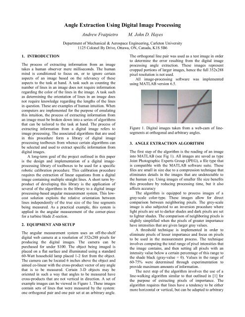
example images can be viewed in Figure 1. These images<br />
contain sets of lines that were measured by the system:<br />
one orthogonal pair and one pair set at an arbitrary angle.<br />
The orthogonal line pair was used as a test image in order<br />
to determine the error resulting from the digital image<br />
processing angle extraction. These images represent<br />
cropped portions of larger images, hence the full 352x288<br />
pixel resolution is not used.<br />
All image-processing software was implemented<br />
using MATLAB version 6.5.<br />
Figure 1. <strong>Digital</strong> images taken from a web-cam of linesegments<br />
at orthogonal and arbitrary angles.<br />
3. ANGLE EXTRACTION ALGORITHM<br />
The first step of the algorithm is the reading of an image<br />
into MATLAB (see Fig 1). All images are saved as type<br />
Joint Photographic Experts Group (JPEG), a file type that<br />
is compatible with the MATLAB software suite. These<br />
files are small in size due to a compression technique that<br />
eliminates details in the images that are undetectable to<br />
the human eye. <strong>Using</strong> images of smaller file size benefits<br />
this procedure by reducing processing time, but it also<br />
affects accuracy<br />
The algorithm is equipped to process images of a<br />
gray-scale color-type. These images allow for direct<br />
comparison between neighboring pixels. The grey-scale<br />
image is also subjected to an inversion procedure where<br />
light pixels are set to darker shades and dark pixels are set<br />
to lighter shades. The comparison of neighboring pixels is<br />
slightly simplified when the pixels of greater importance<br />
have intensities that are given larger gray values.<br />
A threshold technique is implemented in order to<br />
eliminate pixels of lesser importance and focus on pixels<br />
to be used in the measurement process. The technique<br />
involves computing the total range of pixel intensities that<br />
the image contains, and then setting all pixels with an<br />
intensity value below a certain percentage of this range to<br />
the shade black (gray-value = 0). Values in the range of<br />
60-75% were determined through experimentation to<br />
provide maximum amounts of information.<br />
The next step of the algorithm involves the use of a<br />
line-walking algorithm similar to that outlined in [1] for<br />
the purpose of extracting pixels of importance. The<br />
algorithm requires that lines have a tendency to be either<br />
more horizontal or vertical, but can be adapted to arbitrary
orientations. Each pixel of importance is used as the<br />
center point in calculating the second moment in two<br />
directions relative to that location. This moment<br />
calculation at each pixel of importance attempts to locate<br />
a point to be used in a linear regression algorithm,<br />
allowing sub-pixel accuracy regarding the true location of<br />
the lines being measured.<br />
The linear regression technique solves for two linear<br />
equations. The slopes of these linear equations are used to<br />
produce the resulting angle between the lines.<br />
4. EXPERIMENTAL ANALYSIS<br />
Three sets of results were produced for display in this<br />
summary paper. Figure 2 shows a picture that was<br />
generated using a computer graphics program and then<br />
printed to a white sheet of paper. The image is a set of<br />
specified perpendicular lines. Overlaid onto this image are<br />
the two lines that are estimated by the angular<br />
measurement system to represent the lines in the image.<br />
The output includes the equations of both lines and the<br />
angle between them.<br />
Figure 4. Turbine blade Z-section<br />
The results of this measurement can be viewed in Figure<br />
5. It was determined that the corner piece had an angular<br />
value of 75.6927 degrees. The two lines that were used to<br />
determine this angular value can also be viewed in Figure<br />
5.<br />
Figure 2. <strong>Angle</strong> between orthogonal lines.<br />
The system produces a measurement of 89.9807<br />
degrees. This measurement appears to have an error of<br />
0.02%. Further analysis of the significant digits in this<br />
calculation will produce a more realistic error value.<br />
Figure 3 shows an angular measurement made on lines<br />
inclined at arbitrary orientations.<br />
Figure 5. Z-section measurement<br />
5. CONCLUSIONS & FUTURE WORK<br />
From these results we conclude that this algorithm has the<br />
ability to extract the angle between two lines. The<br />
algorithm was applied to lines of several different<br />
orientations and separation angles resulting in angular<br />
measurements that were plausible. The application of<br />
such a system might be used in the area of quick cameraaided<br />
angular measurement in industry.<br />
The future work on this project will involve the<br />
evaluation of the confidence interval of the data points<br />
used in the linear regression. All calculations are carried<br />
through with two decimal places, but the actual<br />
significant digits of the angular measurement have yet to<br />
be determined. In addition, an analysis of the system<br />
using singular value decomposition will be performed.<br />
REFERENCES<br />
Figure 3. Lines at arbitrary angle.<br />
The system is used in the measurement of the cornerpiece<br />
of the turbine blade Z-section of Figure 4.<br />
[1] Ofner, R., O’Leary, P., Leitner, M., 2000, “A<br />
Collection of Algorithms for the Determination of<br />
Construction Points in the Measurement of 3D<br />
Geometries Via Light-Sectioning”, Institute for<br />
Automation, <strong>University</strong> of Leoben, Austria.