
You also want an ePaper? Increase the reach of your titles
YUMPU automatically turns print PDFs into web optimized ePapers that Google loves.
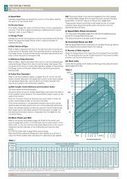
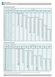
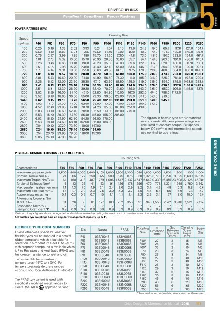
POWER RATINGS (KW)<br />
DRIVE COUPLINGS<br />
<strong>Fenaflex</strong>® <strong>Couplings</strong> - Power Ratings<br />
5<br />
Section<br />
Speed<br />
Coupling Size<br />
rev/min F40 F50 F60 F70 F80 F90 F100 F110 F120 F140 F160 F180 F200 F220 F250<br />
100 0.25 0.69 1.33 2.62 3.93 5.24 7.07 9.16 13.9 24.3 39.5 65.7 97.6 121.0 154.0<br />
200 0.50 1.38 2.66 5.24 7.85 10.50 14.10 18.30 27.9 48.7 79.0 131.0 195.0 243.0 307.0<br />
300 0.75 2.07 3.99 7.85 11.80 15.70 21.20 27.50 41.8 73.0 118.0 197.0 293.0 364.0 461.0<br />
400 1.01 2.76 5.32 10.50 15.70 20.90 28.30 36.60 55.7 97.4 158.0 263.0 391.0 486.0 615.0<br />
500 1.26 3.46 6.65 13.10 19.60 26.20 35.30 45.80 69.6 122.0 197.0 328.0 488.0 607.0 768.0<br />
600 1.51 4.15 7.98 15.70 23.60 31.40 42.40 55.00 83.6 146.0 237.0 394.0 586.0 729.0 922.0<br />
700 1.76 4.84 9.31 18.30 27.50 36.60 49.50 64.10 97.5 170.0 276.0 460.0 684.0 850.0 1076.0<br />
720 1.81 4.98 9.57 18.80 28.30 37.70 50.90 66.00 100.0 175.0 284.0 473.0 703.0 875.0 1106.0<br />
800 2.01 5.53 10.60 20.90 31.40 41.90 56.50 73.30 111.0 195.0 316.0 525.0 781.0 972.0 1229.0<br />
900 2.26 6.22 12.00 23.60 35.30 47.10 63.60 82.50 125.0 219.0 355.0 591.0 879.0 1093.0 1383.0<br />
960 2.41 6.63 12.80 25.10 37.70 50.30 67.90 88.00 134.0 234.0 379.0 630.0 937.0 1166.0 1475.0<br />
1000 2.51 6.91 13.30 26.20 39.30 52.40 70.70 91.60 139.0 243.0 395.0 657.0 976.0 1215.0 1537.0<br />
1200 3.02 8.29 16.00 31.40 47.10 62.80 84.80 110.00 167.0 292.0 474.0 788.0 1172.0<br />
1400 3.52 9.68 18.60 36.60 55.00 73.30 99.00 128.00 195.0 341.0 553.0 919.0<br />
1440 3.62 9.95 19.10 37.70 56.50 75.40 102.00 132.00 201.0 351.0 568.0 945.0<br />
1600 4.02 11.101 21.30 41.90 62.80 83.80 113.00 147.00 223.0 390.0 632.0<br />
1800 4.52 12.401 23.90 47.10 70.70 94.20 127.00 165.00 251.0 438.0<br />
2000 5.03 13.801 26.60 52.40 78.50 105.50 141.00 183.00 279.0<br />
2200 5.53 15.201 29.30 57.601 86.40 115.00 155.00 202.00<br />
2400 6.03 16.601 31.90 62.80 94.20 126.00 170.00<br />
2600 6.53 18.001 34.60 68.10 102.00. 136.00 184.00<br />
2800 7.04 19.401 37.20 73.30 110.00. 147.00<br />
2880 7.24 19.901 38.30 75.40 113.00. 151.00<br />
3000 7.54 20.701 39.90 78.50 118.00. 157.00<br />
3600 9.05 24.901 47.90 94.20<br />
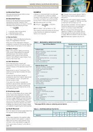
The figures in heavier type are for standard<br />
motor speeds. All these power ratings are<br />
calculated at constant torque. For speeds<br />
below 100 rev/min and intermediate speeds<br />
use nominal torque ratings.<br />
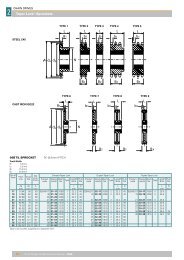
PHYSICAL CHARACTERISTICS – FLEXIBLE TYRES<br />
Coupling Size<br />
Characteristics F40 F50 F60 F70 F80 F90 F100 F110 F120 F140 F160 F180 F200 F220 F250<br />
Maximum speed rev/min 4,500 4,500 4,000 3,600 3,100 3,000 2,600 2,300 2,050 1,800 1,600 1,500 1,300 1,100 1,000<br />
Nominal Torque Nm TK N 24 66 127 250 375 500 675 875 1,330 2,325 3,770 6,270 9,325 11,600 14,675<br />
Maximum Torque Nm TK MAX 64 160 318 487 759 1,096 1,517 2,137 3,547 5,642 9,339 16,455 23,508 33,125 42,740<br />
Torsional Stiffness Nm/ O 5 13 26 41 63 91 126 178 296 470 778 1,371 1,959 2,760 3,562<br />
Max. parallel misalignment mm 1.1 1.3 1.6 1.9 2.1 2.4 2.6 2.9 3.2 3.7 4.2 4.8 5.3 5.8 6.6<br />
Maximum end float mm ± 1.3 1.7 2.0 2.3 2.6 3.0 3.3 3.7 4.0 4.6 5.3 6.0 6.6 7.3 8.2<br />
Approximate mass. kg 0.1 0.3 0.5 0.7 1.0 1.1 1.1 1.4 2.3 2.6 3.4 7.7 8.0 10.0 15.0<br />
Alternating Torque ± Nm<br />
@ 10Hz TKW 11 26 53 81 127 183 252 356 591 940 1,556 2,742 3,918 5,521 7,124<br />
Resonance Factor V R 7 7 7 7 7 7 7 7 7 7 7 7 7 7 7<br />
Damping Coefficient Ψ 0.9 0.9 0.9 0.9 0.9 0.9 0.9 0.9 0.9 0.9 0.9 0.9 0.9 0.9 0.9<br />
Maximum torque figures should be regarded as short duration overload ratings for use in such circumstances as direct-on-line motor starting.<br />
All <strong>Fenaflex</strong> tyre couplings have an angular misalignment capacity up to 4º.<br />
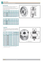
DRIVE COUPLINGS<br />
FLEXIBLE TYRE CODE NUMBERS<br />
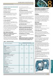
Unless otherwise specified <strong>Fenaflex</strong><br />
flexible tyres will be supplied in a natural<br />
rubber compound which is suitable for<br />
operation in temperatures –50 O C to +50 O C.<br />
A chloroprene compound is available which<br />
is Fire Resistant and Anti-Static (FRAS) and<br />
has greater resistance to heat and oil.<br />
This is suitable for operation in<br />
temperatures –15 O C to +70 O C. For<br />
temperatures outside these ranges<br />
– consult your local Authorised Distributor.<br />
The FRAS tyre variant is used with<br />
specifically modified metal flanges to<br />
create the ATEX approved variant.<br />
Size Natural FRAS<br />
F40 033A0048 033A0068<br />
F50 033B0048 033B0068<br />
F60 033C0048 033C0068<br />
F70 033D0048 033D0068<br />
F80 033E0048 033E0068<br />
F90 033F0048 033F0068<br />
F100 033G0048 033G0068<br />
F110 033H0048 033H0068<br />
F120 033J0048 033J0068<br />
F140 033K0048 033K0068<br />
F160 033L0048 033L0068<br />
F180 033Q0048 033Q0068<br />
F200 033M0048 033M0068<br />
F220 033N0048 033N0068<br />
F250 033P0048 033P0068<br />
Coupling<br />
Size<br />
F40*<br />
F50*<br />
F60*<br />
F70<br />
F80<br />
F90<br />
F100<br />
F110<br />
F120<br />
F140<br />
F160<br />
F180<br />
F200<br />
F220<br />
F250<br />
M<br />
Dimension<br />
(mm)<br />
22<br />
25<br />
33<br />
23<br />
25<br />
27<br />
27<br />
25<br />
29<br />
32<br />
30<br />
46<br />
48<br />
55<br />
59<br />
Gap<br />
Between<br />
Tyre Ends<br />
(mm)<br />
2<br />
2<br />
2<br />
3<br />
3<br />
3<br />
3<br />
3<br />
3<br />
5<br />
5<br />
6<br />
6<br />
6<br />
6<br />
Clamping<br />
Screw<br />
Torque<br />
(Nm)<br />
15<br />
15<br />
15<br />
24<br />
24<br />
40<br />
40<br />
40<br />
50<br />
55<br />
80<br />
105<br />
120<br />
165<br />
165<br />
Screw<br />
Size<br />
M6<br />
M6<br />
M6<br />
M8<br />
M8<br />
M10<br />
M10<br />
M10<br />
M12<br />
M12<br />
M16<br />
M16<br />
M16<br />
M20<br />
M20<br />
*Hexagonal socket caphead clamping screws on these sizes.<br />
Drive Design & Maintenance Manual - 2006 111
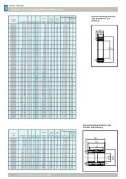
DRIVE COUPLINGS<br />
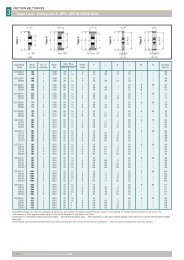
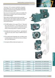
5 <strong>Fenaflex</strong>® <strong>Couplings</strong> - Dimensions<br />
FLANGES<br />
DIMENSIONS OF FENAFLEX FLANGES TYPES B, F & H<br />
Bush<br />
Max Bore Types F & H Type B<br />
Screw<br />
Catalogue ‡ Size Type No. over A C D F G§ M Mass* Inertia*<br />
Code # Metric Inch L E J† L E Key (kg) (kgm 2 )<br />
033A0501 F40 B – 32 – – – 29 33.0 22 M5 104 82 –– –– – 11.0 0.8 0.00074<br />
033A0502 F40 F 1008 25 1" 33.0 22 29 – – – 104 82 –– –– – 11.0 0.8 0.00074<br />
033A0503 F40 H 1008 25 1" 33.0 22 29 – – – 104 82 –– –– – 11.0 0.8 0.00074<br />
033B0501 F50 B – 38 – – – 38 45.0 32 M5 133 100 79 –– – 12.5 1.2 0.00115<br />
033B0502 F50 F 1210 32 1 1 /4" 38.0 25 38 – – – 133 100 79 –– – 12.5 1.2 0.00115<br />
033B0503 F50 H 1210 32 1 1 /4" 38.0 25 38 – – – 133 100 79 –– – 12.5 1.2 0.00115<br />
033C0501 F60 B – 45 – – – 38 55.0 38 M6 165 125 70 –– – 16.5 2.0 0.0052<br />
033C0502 F60 F 1610 42 1 5 /8" 42.0 25 38 – – – 165 125 103 –– – 16.5 2.0 0.0052<br />
033C0503 F60 H 1610 42 1 5 /8" 42.0 25 38 – – – 165 125 103 –– – 16.5 2.0 0.0052<br />
033D0301 F70 B – 50 – – – – 47.0 35 M10 187 144 80 50 13 11.5 3.1 0.009<br />
033D0302 F70 F 2012 50 2" 44.0 32 42 – – – 187 144 80 50 13 11.5 3.1 0.009<br />
033D0303 F70 H 1610 42 1 5 /8" 42.0 25 38 – – – 187 144 80 50 13 11.5 3.0 0.009<br />
033E0301 F80 B – 60 – – – – 55.0 42 M10 211 167 98 54 16 12.5 4.9 0.018<br />
033E0302 F80 F 2517 60 2 1 /2" 58.0 45 48 – – – 211 167 97 54 16 12.5 4.9 0.018<br />
033E0303 F80 H 2012 50 2" 45.0 32 42 – – – 211 167 98 54 16 12.5 4.6 0.017<br />
033F0301 F90 B – 70 – – – – 63.5 49 M12 235 188 112 60 16 13.5 7.1 0.032<br />
033F0302 F90 F 2517 60 2 1 /2" 59.5 45 48 – – – 235 188 108 60 16 13.5 7.0 0.031<br />
033F0303 F90 H 2517 60 2 1 /2" 59.5 45 48 – – – 235 188 108 60 16 13.5 7.0 0.031<br />
033G0301 F100 B – 80 – – – – 70.5 56 M12 254 216 125 62 16 13.5 9.9 0.055<br />
033G0302 F100 F 3020 75 3" 65.5 51 55 – – – 254 216 120 62 16 13.5 9.9 0.055<br />
033G0303 F100 H 2517 60 2 1 /2" 59.5 45 48 – – – 254 216 113 62 16 13.5 9.4 0.054<br />
033H0301 F110 B – 90 – – – – 75.5 63 M12 279 233 128 62 16 12.5 12.5 0.081<br />
033H0302 F110 F 3020 75 3" 63.5 51 55 – – – 279 233 134 62 16 12.5 11.7 0.078<br />
033H0303 F110 H 3020 75 3" 63.5 51 55 – – – 279 233 134 62 16 12.5 11.7 0.078<br />
033J0301 F120 B – 100 – – – – 84.5 70 M16 314 264 143 67 16 14.5 16.9 0.137<br />
033J0302 F120 F 3525 100 4" 79.5 65 67 – – – 314 264 140 67 16 14.5 16.5 0.137<br />
033J0303 F120 H 3020 75 3" 65.5 51 55 – – – 314 264 140 67 16 14.5 15.9 0.130<br />
033K0301 F140 B – 130 – – – – 110.5 94 M20 359 311 178 73 17 16.0 22.2 0.254<br />
033K0302 F140 F 3525 100 4" 81.5 65 67 – – – 359 311 178 73 17 16.0 22.3 0.255<br />
033K0303 F140 H 3525 100 4" 81.5 65 67 – – – 359 311 178 73 17 16.0 22.3 0.255<br />
033L0301 F160 B – 140 – – – – 117 102 M20 402 345 187 78 19 15.0 35.8 0.469<br />
033L0302 F160 F 4030 115 4 1 /2" 92.0 77 80 – – – 402 345 197 78 19 15.0 32.5 0.380<br />
033L0303 F160 H 4030 115 4 1 /2" 92.0 77 80 – – – 402 345 197 78 19 15.0 32.5 0.380<br />
033Q0301 F180 B – 150 – – – – 137 114 M20 470 398 200 94 19 23.0 49.1 0.871<br />
033Q0302 F180 F 4535 125 5" 112.0 89 89 – – – 470 398 205 94 19 23.0 42.2 0.847<br />
033Q0303 F180 H 4535 125 5" 112.0 89 89 – – – 470 398 205 94 19 23.0 42.2 0.847<br />
033M0301 F200 B – 150 – – – – 138 114 M20 508 429 200 103 19 24.0 58.2 1.301<br />
033M0302 F200 F 4535 125 5" 113.0 89 89 – – – 508 429 205 103 19 24.0 53.6 1.281<br />
033M0303 F200 H 4535 125 5" 113.0 89 89 – – – 508 429 205 103 19 24.0 53.6 1.281<br />
033N0301 F220 B – 160 – – – – 154.5 127 M20 562 474 218 118 20 27.5 79.6 2.142<br />
033N0302 F220 F 5040 125 5" 129.5 102 92 – – – 562 474 223 118 20 27.5 72.0 2.104<br />
033N0303 F220 H 5040 125 5" 129.5 102 92 – – – 562 474 223 118 20 27.5 72.0 2.104<br />
033P0301 F250 B – 190 – – – – 161.5 132 M20 628 532 254 125 25 29.5 104.0 3.505<br />
Dimensions in millimetres unless otherwise stated.<br />
§ G is the amount by which clamping screws need to be withdrawn to release tyre.<br />
† J is the wrench clearance to allow for tightening/loosening the bush on the shaft and the clamp ring screws on sizes F40. F50 and F60. The use of a shortened<br />
wrench will allow this dimension to be reduced.<br />
M is half the distance between flanges. Shaft ends, although normally located twice M apart, can project beyond the flanges as shown. In this event allow<br />
sufficient space between shaft ends for end float and misalignment.<br />
* Mass and inertia figures are for single flange with mid range bore and include clamping ring, screws and washers and half tyre.<br />
‡ For pilot bore 'B' flange code as listed. Flanges are also available finish bored with keyway if required. Bore must be specified on order.<br />
# Note: On sizes F70, 80, 100 and 120 the 'F' direction bush is larger than that in the 'H'direction.<br />
Note: Flange assemblies comprise hub, clamp ring and clamp ring screws/washers.<br />
112 Drive Design & Maintenance Manual - 2006