
Create successful ePaper yourself
Turn your PDF publications into a flip-book with our unique Google optimized e-Paper software.
R<br />
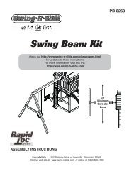
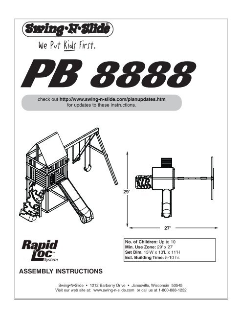
PB 8888<br />
check out http://www.swing-n-slide.com/planupdates.htm<br />
for updates to these instructions.<br />
29'<br />
27'<br />
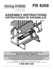
ASSEMBLY INSTRUCTIONS<br />
No. of Children: Up to 10<br />
Min. Use Zone: 29' x 27'<br />
Set Dim. 15'W x 13'L x 11'H<br />
Est. Building Time: 5-10 hr.<br />
<strong>Swing</strong>•N•<strong>Slide</strong> • 1212 Barberry Drive • Janesville, Wisconsin 53545<br />
Visit our web site at: www.swing-n-slide.com or call us at 1-800-888-1232
R<br />
Safety Checklist for <strong>Swing</strong>-N-<strong>Slide</strong> Play Sets and Accessories<br />
Observing the following statements and warnings reduces the likelihood of serious or fatal injury<br />
Installation Safety – Have You:<br />
Consulted the assembly instructions supplied with your particular model?<br />
Noted this accessory is to be used only on <strong>Swing</strong>•N•<strong>Slide</strong> approved designs? (Do not alter its design or add/remove components.)<br />
Made sure all hardware is tightened securely? (Supplied bolt covers must also be fastened securely.)<br />
Using a hacksaw, cut off all protruding threaded ends of bolts and other fasteners and remove any sharp edges with<br />
a metal file as needed, and coated fastener ends with lead free paint?<br />
Placed the equipment on level ground, not less than six feet (1.8 meters) from any structure or obstruction such as a fence, garage,<br />
house, overhanging branches, laundry lines, or electrical wires?<br />
Made sure home playground equipment is not installed over concrete, asphalt, packed earth or any other hard surface? (A fall onto<br />
a hard surface can result in serious injury to the equipment user.)<br />
Verified that suspended climbing ropes, chain,or cable are secured at both ends?<br />
Consulted in assembly instructions of your particular model for minimum use zones?<br />
Used a water sealant on your play set to protect the wood and prevent cracking and warping?<br />
Followed all anchoring and shock absorbing surfacing requirements on the back of this sheet as they apply?<br />
Made sure not to allow children to use equipment until it is properly installed?<br />
Made sure to adjust all swings so there is a minimum 8'' clearance between the swing and the ground surface?<br />
Operating Safety – Have You:<br />
Determined that on-site adult supervision is provided for children of all ages?<br />
Warned children the following before allowing them to use the equipment?<br />
Not to walk close to, in front of, behind or between moving items.<br />
Not to twist swing or any other accessory chains or ropes or loop them over the top support bar since this will reduce the<br />
strength of chain or rope.<br />
Not to swing empty seats or other accessories.<br />
Not to slide down swing chains.<br />
Be sure to sit in the center of the swing seat and other accessories with full weight on the seat.<br />
Not to attach items to the playground equipment that are not specifically designed for use with the equipment such as but not<br />
limited to, jump ropes, clotheslines, pet leashes, cables and chain. They may cause a strangulation hazard.<br />
Not to climb or walk on the top of swing beams, railings or roof.<br />
Not to use equipment in a manner other than intended.<br />
Not to get off equipment while it is in motion.<br />
Not to climb on the equipment when it is wet.<br />
Be sure to go down slides feet first.<br />
Determined that only one child per planned occupant seat should be allowed on this set at one time.<br />
Determined children must be dressed appropriately for play. Avoid hooded jackets, bicycle helmets, clothing with draw strings and<br />
loose fitting clothes which could become entangled or snagged on equipment.<br />
Determined that suspended climbing ropes, chain, or cable cannot be looped back upon itself.<br />
Made certain the slide is placed so that is is not in direct sunlight.<br />
Safety Maintenance – At the beginning of every season and twice monthly thereafter:<br />
Rake and check depth of loose fill protective surfacing material to prevent compaction and maintain appropriate depth. Replace as<br />
necessary.<br />
Check all nuts, bolts and C-Links during the usage season for tightness and tighten as required. (It is<br />
particularly important that this procedure be followed at the beginning of each season.)<br />
To prevent the deterioration of materials, remove plastic swing seats and other plastic accessories when outdoors temp dips down to<br />
or below 32° F and take indoors.<br />
Oil all metallic moving parts monthly during usage period.<br />
Check all hardware and equipment for sharp edges during usage season. (Replace when necessary. It is especially<br />
important to do this at the beginning of each new season.)<br />
Check swing seats, chains, ropes and cables monthly during usage season for evidence of deterioration. Severe rusting or excessive wear,<br />
especially near the top swing hanger or at the seat connection are evidence of chain deterioration. Cracks in the protective plastic sleeve<br />
or seat itself are also signs of deterioration. If any of these conditions exist, call 1-800-888-1232 to order replacement accessories.<br />
Sand rusted metal parts and repaint using non-lead based paint.<br />
Check all wood members for deterioration and splinters. Sand down splinters and replace deteriorating wood members.<br />
Disposal Instructions<br />
When the equipment is taken out of service, it must be disassembled and disposed of in such a way that no unreasonable hazards<br />
will exist at the time the set is discarded.<br />
Important! Additional Safety Instructions for all <strong>Swing</strong>-N-<strong>Slide</strong> Playground Equipment.<br />
Save this instruction sheet in the event the manufacturer needs to be contacted.<br />
2
This product is intended for single family home/residential use only and not intended for use in any public setting.<br />
Placement in any public setting constitutes a misuse of this product.<br />
IMPORTANT!<br />
ADDITIONAL REQUIRED SAFETY INSTAL<strong>LA</strong>TION INSTRUCTIONS<br />
According to ASTM requirements, all kits must be anchored to the ground and, if the unit has a climbing rope, the rope end must be anchored to the ground. If soil conditions<br />
permit stakes to be pulled out easily, cementing into ground is necessary.<br />
• To anchor the unit to the ground, Follow the instructions included in this plan for applying Anchor-It devices to your unit, or use 2" x 4" x 18" (45mm x 95mm x 457mm) pressuretreated<br />
stakes. Pound stakes into ground at least 12" (305mm) at all inside corners of the posts (including A-frame legs and climbing unit posts). Attach with four (4) 16D (3-1/2")<br />
galvanized nails per stake into each tower and/or A-frame upright.<br />
• If the unit has a climbing rope, anchor the rope end.<br />
• Once the unit is completely assembled and before children are allowed to play on it, proper shock-absorbing surfacing material must be installed. This may be accomplished by<br />
using loose-fill materials at a sufficient depth. The Consumer Product Safety Commission “Handbook for Public Playground Safety” lists the following materials and required<br />
depths that are sufficient for home/residential application. For fall height protection up to 9 ft. (2.742m) [recommended for <strong>Swing</strong>•N•<strong>Slide</strong> kits]:<br />
LOOSE FILL MATERIAL<br />
REQUIRED (UNCOMPRESSED) DEPTH 1 in. (mm)<br />
Wood Mulch<br />
9" (229mm)<br />
Double Shredded Bark Mulch<br />
9" (229mm)<br />
Uniform Wood Chips<br />
12" (305mm)<br />
Fine Sand<br />
12" (305mm)<br />
Fine Gravel<br />
12" (305mm)<br />
These depths were derived from the CPSC Handbook. <strong>Swing</strong>•N•<strong>Slide</strong> has not done independent tests to determine these required depths.<br />
When properly installed, shock absorbing material will completely cover the horizontal baseboards on climbing units. This protective surfacing must extend a minimum of 6 ft.<br />
(1.828m) in all directions from the perimeter of the equipment or from the outermost edges of any component. For example, a slide extending beyond the platform must have<br />
protective surfacing at least 6 ft. (1.828mm) out from both sides as well as the end. For swings, the protective surface must extend at least 14 ft. (6m) out from both the back and<br />
front of the swing when the swing is in its rest position.<br />
For further information on playground safety, the Consumer Product Safety Commission<br />
(CPSC) publishes the Outdoor Home Playground Safety Handbook which can be downloaded for free<br />
from www.cpsc.gov. An additional resource is the American Society of Testing and Materials (ASTM)<br />
Standard Consumer Safety Performance Specification for Home Playground Equipment (ASTM F1148)<br />
which can be purchased and downloaded from www.astm.org.<br />
<strong>Swing</strong>-N-<strong>Slide</strong>® MANUFACTURERS LIMITED WARRANTY<br />
<strong>Swing</strong>-N-<strong>Slide</strong>® takes great pride in the quality and durability of our products. Our Manufacturer’s Limited Warranty provides confidence and demonstrates our commitment<br />
to providing quality residential playground products.<br />
MANUFACTURER’S LIFETIME LIMITED WARRANTY<br />
<strong>Swing</strong>-N-<strong>Slide</strong>® warrants its thermoformed slides and climbing mountains to be free from defects in workmanship and materials, under normal use and conditions, for the<br />
lifetime of the product.<br />
MANUFACTURER’S 5 YEAR LIMITED WARRANTY<br />
<strong>Swing</strong>-N-<strong>Slide</strong>® warrants its Custom Ready-to-Build Play Set kits and accessories to be free from defects in workmanship and materials, under normal use and conditions,<br />
for a period of 5 years.<br />
MANUFACTURER’S 5 YEAR LIMITED WARRANTY<br />
<strong>Swing</strong>-N-<strong>Slide</strong>® warrants its No-Cut and Wood Complete Ready-to-Assemble Play Set kits against wood rot and termite damage, and to be free from defects in<br />
workmanship and materials, under normal use and conditions, for a period of 5 years for structural wood components.<br />
Cosmetic defects that do not affect the structural integrity of the product, or natural defects of wood such as warping, splitting, checking, twisting, shrinkage, swelling or<br />
any other physical properties of wood that do not present a safety hazard, are not covered by this warranty.<br />
MANUFACTURER’S ONE YEAR WARRANTY<br />
<strong>Swing</strong>-N-<strong>Slide</strong>® warrants its canopy roofs and/or tarps, and Timber GLOVE lumber wrap to be free from defects in workmanship and materials, under normal use and<br />
conditions, for a period of one year.<br />
<strong>Swing</strong>-N-<strong>Slide</strong>® will repair, or at its discretion, replace any part within the stated warranty period which is defective in workmanship or materials. This decision is subject<br />
to verification of the defect upon delivery of the defective part to <strong>Swing</strong>-N-<strong>Slide</strong>® at 1212 Barberry Drive, Janesville, Wisconsin, 53545. Any part(s) returned to <strong>Swing</strong>-N-<br />
<strong>Slide</strong>® must have prior approved Return Authorization Number and proof of purchase, including the date of purchase. This warranty is valid only if the product is used for<br />
the purpose for which it was designed and installed at a residential, single family dwelling. This warranty is void if the product is put to commercial or institutional use. This<br />
warranty does not cover (a) products which have been damaged by acts of Nature, negligence, misuse, or accident, or which have been modified or repaired by<br />
unauthorized persons; (b) the cost of labor; or the cost of shipping the product, any part, or any replacement product or part.<br />
<strong>Swing</strong>-N-<strong>Slide</strong>® DISC<strong>LA</strong>IMS ALL OTHER REPRESENTATIONS AND WARRANTIES OF ANY KIND, EXPRESS, IMPLIED, STATUTORY OR OTHERWISE, INCLUDING THE<br />
IMPLIED WARANTIES OF MERCHANTIBILITY AND FITNESS FOR A PARTICU<strong>LA</strong>R PURPOSE. <strong>Swing</strong>-N-<strong>Slide</strong>® WILL NOT BE LIABLE FOR ANY INCIDENTAL OR<br />
CONSEQUENTIAL DAMAGES. This warranty is non-transferable and does not extend to the owners of the product subsequent to the original purchaser. Some states do not<br />
allow limitations on implied warranties or exclusion of incidental or consequential damages, so these restrictions may not be applicable to you. This warranty gives you<br />
specific legal rights. You may also have other rights, which vary from state to state.<br />
This warranty also does not apply to:<br />
• Structures not erected, maintained or inspected in conformance with <strong>Swing</strong>-N-<strong>Slide</strong>® installation plans<br />
• Structures that have had parts added or substituted not in conformance with <strong>Swing</strong>-N-<strong>Slide</strong>® installation plans<br />
• Parts that have been modified, altered or misused<br />
• Parts that have not been used as designed or intended<br />
• Damage due to acts of Nature, vandalism, abnormal use or abuse as determined by <strong>Swing</strong>-N-<strong>Slide</strong>®<br />
3
TOOLS REQUIRED<br />
ELECTRIC DRILL 1/2" SOCKET & WRENCH HAMMER<br />
TAPE MEASURE<br />
SAFETY G<strong>LA</strong>SSES<br />
& DUST MASK<br />
PHILLIPS BIT<br />
CARPENTER'S SQUARE<br />
(32) 1-1/4" lag screw<br />
(4) 5/16''Hex Head Lag Screws<br />
(54) 2" lag screw<br />
(4) 1-3/4'' panhead screws<br />
(6) Tarp Washers<br />
(8) 3/4'' panhead screws<br />
(2) 1/2'' panhead screws<br />
(8) 3/4'' screws<br />
(119) 1-1/4'' screws<br />
(4) 1/4'' flat washers<br />
(6) T-Nut<br />
(3) 1-1/2'' screws<br />
(296) 2-1/2'' screws<br />
(6) 5/16'' flat washers<br />
(2) Wood Loc Washers<br />
(6) 3'' screws<br />
(2) Loc-Nuts<br />
(2) 6-1/2'' Bolts<br />
4<br />
(6) Slotted Beam Clamp
R<br />
(8) Shelf-Loc<br />
(2) Step Brackets<br />
Note: (1 Left, 1 Right)<br />
(2) 3X3 TO 4X4<br />
Shelf-Loc<br />
(6) Wrap-Loc<br />
(2) Split Beam bracket<br />
(2) EZ Frame Brackets<br />
(1) REALTREE®<br />
Printed Tarp<br />
(1) Window Frame<br />
(4) Anchor-It<br />
(1) T20 Torx® Bit<br />
(1) T30 Torx® Bit<br />
(4) Anchor-It Straps<br />
(1) 3/8" DRILL BIT<br />
PB 8888<br />
Plan<br />
(1) Plan<br />
THIS PRODUCT IS<br />
INTENDED FOR USE<br />
BY CHILDREN FROM<br />
AGES 2-10 YEARS<br />
For Home / Residential<br />
Use ONLY<br />
1212 Barberry Drive<br />
Janesville, WI 53545<br />
1-800-888-1232<br />
www.swing-n-slide.com<br />
(1) Name Plate<br />
5
Playset Assembly Instructions<br />
(1) REALTREE® <strong>Slide</strong><br />
with hardware<br />
(1) REALTREE® Climbing Mountain<br />
with Hardware<br />
450 lb Weight Limit<br />
(1) Ring-Trap Combo<br />
(2) Reg Duty <strong>Swing</strong> Seat<br />
with Hardware<br />
115 lb Weight Limit<br />
(6) <strong>Swing</strong> Hanger<br />
with Hardware<br />
(2) Play Handles<br />
with Hardware<br />
(8) Climbing Rocks w/ Hardware<br />
230 lb<br />
Weight Limit<br />
MANUFACTURER’S WARRANTY on REALTREE® products<br />
<strong>Swing</strong>-N-<strong>Slide</strong>® warrants its REALTREE® <strong>Slide</strong>, REALTREE® climbing mountain, REALTREE® cliff climber and<br />
REALTREE® canopy roof to be free from defects in workmanship and materials, under normal use and conditions, for a<br />
period of one year. This warranty supersedes any and all warrantees related to slides, climbing mountains, cliff climbers and<br />
canopy roofs.<br />
6
PB 8888 Board List<br />
Playset Assembly Instructions<br />
(2) 2'' x 4'' x 5''<br />
(3) 2'' x 4'' x 17-1/4'' (<strong>Slide</strong> Stake)<br />
(2) 2'' x 4'' x 22''<br />
(2) 2'' x 4'' x 25-1/2''<br />
(4) 2'' x 4'' x 36''<br />
(1) 2'' x 4'' x 47''<br />
(8) 2'' x 4'' x 47-1/2''<br />
(1) 1'' x 4'' x 7-7/16'' Window Top<br />
N OM INAL M ATERIAL SIZE<br />
LISTED SIZE<br />
TRUE SIZE<br />
E nglish(*) Metric(Cm) English(*) Metric(Cm)<br />
1x4 2.5x7.6 3/4x3-1/2 1.9x9<br />
1x6 2.5x15.3 3/4x5-1/2 1.9x14<br />
5/4x4 3.2x10.2 1x3-1/2 2.5x9<br />
5/4x6 3.2x15.3 1x5-1/2 2.5x14<br />
2x2 5x5 1-1/2x1-1/2 3.8x3.8<br />
2x3 5x7.6 1-1/2x2-1/2 3.8x6.4<br />
2x4 5x10 1-1/2x3-1/2 3.8x9<br />
2x6 5x15.3 1-1/2x5-1/2 3.8x14<br />
3x3 7.6x7.6 3 x3 7.6x7.6<br />
4x4 10x10 3-1/2x3-1/2 9x9<br />
(*) Estimated Sizing Due to Cutting Process<br />
(1) 1'' x 4'' x 7-3/4'' Window Bottom<br />
(1) 1'' x 4'' x 10'' Window Sill<br />
(2) 1'' x 4'' x 15-5/16'' Shutters<br />
(1) 1'' x 4'' x 18''<br />
(3) 1'' x 4'' x 20-1/2''<br />
(8) 1'' x 4'' x 24''<br />
(8) 1'' x 4'' x 30''<br />
(2) 1'' x 4'' x 30'' Window Sides<br />
(2) 1'' x 4'' x 41-1/4''<br />
(7) 1'' x 4'' x 46''<br />
(1) 1'' x 4'' x 46-3/4''<br />
(23) 1'' x 4'' x 47-1/2''<br />
(2) 5/4'' x 4'' x 20'' Angle Brace<br />
(1) 1'' x 3'' x 23-1/2''<br />
NOTE:<br />
SWING-N-SLIDE MANUFACTURES<br />
MULTIPLE KITS FROM A CENTRAL<br />
WOOD PACK. DUE TO THIS YOU MAY<br />
RECEIVE EXTRA BOARDS THAT THIS<br />
PROJECT DOES NOT REQUIRE.<br />
RETAIN THIS LUMBER FOR FUTURE<br />
PROJECTS.<br />
(2) 3'' x 3-1/2'' x 94''<br />
(4) 3'' x 3'' x 94'' (Plastic Coated)<br />
(1) 4'' x 4'' x 47-1/2''<br />
(1) 4'' x 6'' x 94'' <strong>Swing</strong> Beam<br />
7
Playset Assembly Instructions<br />
How to select the correct fastener<br />
Use these 2 pictorial guides to help select the correct fastener(s) for the<br />
lumber attachment you are making. Each diagram will highlight the correct<br />
number of fasteners to use, and where to attach them.<br />
1'' x 4'' to 3'' x 3''<br />
(3) 2-1/2'' screws<br />
Apply 2-1/2" screws to the 1''x4'' boards<br />
when attaching to 3''x3'' uprights.<br />
1'' x 4'' to 1'' x 4''<br />
(2) 1-1/4'' screws<br />
Use 1-1/4'' screws when mounting 1'' x 4''<br />
boards to 1''x4'' boards.<br />
8
Playset Assembly Instructions<br />
Understanding how the Bracket System Works<br />
ASSEMBLY INSTRUCTIONS • INSTRUCCIONES PARA ARMAR • DIRECTIVES D’ASSEMB<strong>LA</strong>GE<br />
Example of a Shelf-Loc bracket connection.<br />
Shelf-Loc Bracket<br />
1 2 3<br />
4<br />
Wrap-Loc<br />
CORRECT!<br />
WRONG!<br />
Brackets<br />
''clipped''<br />
brackets NOT<br />
interlocked!<br />
Example of a Shelf-Loc bracket connection.<br />
Look for ''TOP'' stamp on<br />
bracket for correct orientation.<br />
TOP<br />
Introduction to the Bracket system<br />
Top of bracket<br />
1. ALWAYS Use 1-1/4'' or 2'' lag screws on<br />
all brackets.<br />
2. Brackets ''clip'' to each other. NEVER<br />
position in a non-interlocking position.<br />
GAP<br />
Wrap-Loc<br />
NOTE: P<strong>LA</strong>CE SCREWS IN BRACKETS ONLY<br />
WHERE INSTRUCTED. DO NOT<br />
FILL EVERY HOLE IN BRACKET.<br />
THIS WILL LEAD TO HARDWARE<br />
SHORTAGES.<br />
Shelf-Loc<br />
Brackets Clip Together<br />
Bottom of bracket<br />
(Hole locations close to bottom)<br />
DO NOT USE <strong>LA</strong>G<br />
SCREWS HERE<br />
Use Lag Screws Only Where<br />
Brackets Attach<br />
9
Playset Assembly Instructions<br />
Look for ‘’TOP’’<br />
stamp on brackets<br />
while installing.<br />
TOP<br />
GAP on<br />
this side<br />
Frame 1 Construction<br />
Fig.1b<br />
DO NOT USE <strong>LA</strong>G<br />
SCREWS HERE<br />
Use Lag Screws Only Where<br />
Brackets Attach<br />
Fig.1a<br />
3'' x 3'' x 94''<br />
83-1/4''<br />
(2)<br />
2'' Lag Screws<br />
per joint<br />
(2)<br />
1-1/4'' Lag<br />
Screws<br />
per joint<br />
Fig.1c<br />
DO NOT USE <strong>LA</strong>G<br />
SCREWS HERE<br />
Use Lag Screws Only Where<br />
Brackets Attach<br />
(2)<br />
1-1/4'' Lag Screws<br />
per joint<br />
(2)<br />
2'' Lag Screws<br />
per joint<br />
47-1/4''<br />
Frame 1<br />
A. Frame 1 Construction<br />
1-1/4'' Lag screw<br />
1. Measure and position brackets on 3'' x 3'' as shown in (Fig.1a).<br />
Note: Secure Shelf Lock with (2) Lag Screws only at this time.<br />
2'' Lag screw<br />
10
Playset Assembly Instructions<br />
•WARNING•<br />
Avoid splitting your<br />
lumber by offsetting<br />
your screws at least<br />
3/4’’ from edge.<br />
Double check to make<br />
sure structure is square<br />
Tip: Flex brackets to make installation of<br />
2'' x 4'' easier<br />
Frame 1 Construction<br />
(3)<br />
2-1/2'' screws<br />
per joint<br />
Fig. 2<br />
1'' x 4'' x 47-1/2''<br />
(3)<br />
2-1/2'' screws<br />
(per joint)<br />
Approx. 1/4''<br />
Fig. 2a<br />
(2) 1-1/4'' lag screws<br />
and<br />
(3) 2'' lag screws<br />
per bracket<br />
Fig. 2b<br />
STEP<br />
BRACKET<br />
(6)<br />
1-1/4'' screws<br />
(per Bracket)<br />
2'' x 4'' x 47-1/2''<br />
(3)<br />
2-1/2'' screws<br />
(per joint)<br />
5/4'' x 4'' x 20''<br />
Angle Brace<br />
Fig. 2c<br />
(2)<br />
1-1/4'' Lag<br />
(3)<br />
2-1/2'' screws<br />
per joint<br />
1'' x 4'' x 47-1/2''<br />
Frame 1<br />
(3)<br />
2'' Lag<br />
NOTE: Upper screws are (2) 1-1/4'' Lag<br />
Screws, Lower screws are (3) 2'' Lag<br />
Screws.<br />
1-1/4'' Lag screw<br />
1-1/4'' screw<br />
2'' Lag screw<br />
2-1/2'' screw<br />
A. Frame 1 Construction cont.<br />
2. Attach boards as shown in (Fig. 2) through (Fig. 2c).<br />
11
Frame 2<br />
Playset Assembly Instructions<br />
Look for ‘’TOP’’<br />
stamp on brackets<br />
while installing.<br />
TOP<br />
GAP on<br />
this side<br />
Fig. 3<br />
3'' x 3'' x 94''<br />
Frame 2 Construction<br />
Fig. 3a<br />
DO NOT USE <strong>LA</strong>G<br />
SCREWS HERE<br />
Use Lag Screws Only Where<br />
Brackets Attach<br />
(2)<br />
1-1/4'' Lag Screws<br />
per joint<br />
(2)<br />
1-1/4'' Lag<br />
Screws<br />
per joint<br />
47-1/4''<br />
A. Frame 2 Construction<br />
1. Measure and position brackets on 3'' x 3'' as shown in (Fig.3).<br />
Note: Secure Shelf Lock with (2) Lag Screws only at this time.<br />
1-1/4'' Lag screw<br />
12
Playset Assembly Instructions<br />
Frame 2 Construction<br />
(3)<br />
2-1/2'' screws<br />
per joint<br />
Fig. 4<br />
•WARNING•<br />
Avoid splitting your<br />
lumber by offsetting<br />
your screws at least<br />
3/4’’ from edge.<br />
Tip: Flex brackets to make installation of<br />
2'' x 4'' easier<br />
1'' x 4'' x 47-1/2''<br />
(2) 1-1/4'' lag screws<br />
and<br />
(3) 2'' lag screws<br />
per bracket<br />
(3)<br />
2-1/2'' screws<br />
(per joint)<br />
Fig. 4a<br />
2'' x 4'' x 47-1/2''<br />
Approx. 1/4''<br />
Fig. 4b<br />
(2)<br />
1-1/4'' Lag<br />
(3)<br />
2-1/2'' screws<br />
per joint<br />
(3)<br />
2-1/2'' screws<br />
per joint<br />
(3)<br />
2'' Lag<br />
NOTE: Upper screws are (2) 1-1/4'' Lag<br />
Screws, Lower screws are (3) 2'' Lag<br />
Screws.<br />
1'' x 4'' x 47-1/2''<br />
Frame 2<br />
1-1/4'' Lag screw<br />
A. Frame 2 Construction cont.<br />
Double check to make<br />
sure structure is square<br />
2'' Lag screw<br />
2. Attach boards as shown in (Fig. 4) through (Fig. 4b).<br />
2-1/2'' screw<br />
13
Playset Assembly Instructions<br />
Fig. 5<br />
1'' x 4'' x 47-1/2''<br />
(3)<br />
2-1/2'' screws<br />
per joint<br />
(3)<br />
2-1/2'' screws<br />
per joint<br />
Tip: Flex brackets to make installation of<br />
2'' x 4'' easier<br />
2'' x 4'' x 47-1/2''<br />
(2) 1-1/4'' lag screws<br />
and<br />
(3) 2'' lag screws<br />
per bracket<br />
1'' x 4'' x 47-1/2''<br />
(2) 1-1/4'' lag screws<br />
and<br />
(3) 2'' lag screws<br />
per bracket<br />
Approx. 1/4''<br />
Fig. 5a<br />
Fig. 5b<br />
(2)<br />
1-1/4'' Lag<br />
1'' x 4'' x 47-1/2''<br />
(3)<br />
2-1/2'' screws<br />
per joint<br />
2'' x 4'' x 47-1/2''<br />
Frame 1<br />
(3)<br />
2'' Lag<br />
NOTE: Upper screws are (2) 1-1/4'' Lag<br />
Screws, Lower screws are (3) 2'' Lag<br />
Screws.<br />
1'' x 4'' x 47-1/2''<br />
(3)<br />
2-1/2'' screws<br />
per joint<br />
A. Frame Construction cont.<br />
1-1/4'' Lag screw<br />
1. Attach 1''x4'' and 2''x4'' boards as shown.<br />
2'' Lag screw<br />
2-1/2'' screw<br />
14
Playset Assembly Instructions<br />
Fig. 6<br />
Tip: Flex brackets to make installation of<br />
2'' x 4'' easier<br />
(3)<br />
2-1/2'' screws<br />
per joint<br />
Approx. 1/4''<br />
Fig. 6a<br />
(2) 1-1/4'' lag screws<br />
and<br />
(3) 2'' lag screws<br />
per bracket<br />
47-1/2'' Outside to Outside<br />
Fig. 6b<br />
(2)<br />
1-1/4'' Lag<br />
(3)<br />
2'' Lag<br />
NOTE: Upper screws are (2) 1-1/4'' Lag<br />
Screws, Lower screws are (3) 2'' Lag<br />
Screws.<br />
Frame 1<br />
Frame 2<br />
(3)<br />
2-1/2'' screws<br />
per joint<br />
A. Frame Construction (cont.)<br />
1. Attach Frame 2 to Frame 1 as shown.<br />
Note: Outside to Outside measurement of<br />
uprights on all four sides of the tower<br />
should be 47-1/2''.<br />
1-1/4'' Lag screw<br />
2'' Lag screw<br />
2-1/2'' screw<br />
15
Playset Assembly Instructions<br />
Fig. 7<br />
Fig. 7a<br />
(2)<br />
2-1/2''<br />
screws<br />
per joint<br />
1'' x 4'' x 41-1/4''<br />
(2)<br />
2-1/2''<br />
screws<br />
per joint<br />
2'' x 4'' x 47-1/2''<br />
18-1/2''<br />
FRONT<br />
1'' x 4'' x 41-1/4''<br />
1'' x 4'' x 18''<br />
FRONT<br />
(4)<br />
1-1/4''<br />
screws<br />
UNDER DECK VIEW<br />
1-1/4'' screw<br />
2-1/2'' screw<br />
B. Install Deck Boards<br />
1. Install (2) 1'' x 4'' deck boards as shown in (Fig. 7).<br />
2. Attach 2'' x 4'' to deck boards using 2-1/2'' screws as shown in (Fig. 7).<br />
3. Attach 1'' x 4'' <strong>Slide</strong> Support as shown in (Fig. 7a).<br />
16
Playset Assembly Instructions<br />
Fig. 8<br />
(10) 1'' x 4'' x 47-1/2''<br />
(2)<br />
2-1/2''<br />
screws<br />
per joint<br />
NOTE: 1/2'' Gap Between Boards is Typical<br />
2-1/2'' screw<br />
B. Install Deck Boards<br />
1. Install (10) 1'' x 4'' deck boards to structure as shown (Fig. 8).<br />
2. Use two 2-1/2'' screws at center and each end of deck boards.<br />
Note: Screws at center will attach to center support.<br />
17
Playset Assembly Instructions<br />
Fig. 9<br />
Fig. 9a<br />
(5)<br />
2-1/2''<br />
screws<br />
1'' x 4'' x 20-1/2''<br />
1'' x 4'' x 20-1/2''<br />
(5)<br />
2-1/2''<br />
screws<br />
(3)<br />
2-1/2''<br />
screws<br />
per joint<br />
1'' x 4'' x 47-1/2''<br />
(5)<br />
2-1/2''<br />
screws<br />
1'' x 4'' x 20-1/2''<br />
(3)<br />
2-1/2''<br />
screws<br />
per joint<br />
78-1/2''<br />
1'' x 4'' x 47-1/2''<br />
1'' x 4'' x 47-1/2''<br />
(3)<br />
2-1/2''<br />
screws<br />
per joint<br />
1'' x 4'' x 47-1/2''<br />
(3)<br />
2-1/2''<br />
screws<br />
per joint<br />
2-1/2'' screw<br />
C. Install Barrier Support Boards<br />
1. Install (3) 1'' x 4'' lower Barrier Support Boards as shown in (Fig. 9).<br />
2. Install (3) 1'' x 4'' upper Barrier Support Boards as shown in (Fig. 9a).<br />
18
Playset Assembly Instructions<br />
Tip: Flex brackets to make installation of<br />
4'' x 4'' easier<br />
Approx. 1/4''<br />
Fig. 10<br />
Fig. 3a<br />
Fig. 10a<br />
4'' x 4'' x 47-1/2''<br />
(4)<br />
2'' Lag Screws<br />
per brackets<br />
ATTENTION:<br />
Unit has been rotated<br />
1/4 turn Counter<br />
Clockwise for this view.<br />
2'' Lag screw<br />
C. Install Lower Rail Boards<br />
1. Install 4’’ x 4’’ <strong>Swing</strong> Beam Support as shown in<br />
(Fig. 10) and (Fig. 10a).<br />
19
Playset Assembly Instructions<br />
Fig. 11<br />
3/8’’ Hole Locations<br />
(2) Wood<br />
Loc Washers<br />
D. <strong>Swing</strong> Beam Hole Locations<br />
1. Install <strong>Swing</strong> Hangers into swing beam at<br />
locations shown.<br />
Note: You will need to drill (2) 3/8'' holes in<br />
your <strong>Swing</strong> Beam using the 3/8'' drill bit<br />
included with your kit. See (Fig. 11) for the<br />
proper location of these holes.<br />
94''<br />
26-1/2''<br />
Note:<br />
You will need to drill these<br />
two holes in your <strong>Swing</strong><br />
Beam.<br />
15''<br />
11-1/2''<br />
11-1/2''<br />
3-1/2''<br />
20
Playset Assembly Instructions<br />
Hammer<br />
Fig. 11a<br />
T-nut<br />
t-nut<br />
3/8'' hole<br />
Bottom Beam Clamp<br />
(4) 1-1/4'' screws<br />
Use Screwdriver to aid in tightening<br />
1-1/4'' screw<br />
E. <strong>Swing</strong> Beam Drill Locations<br />
<strong>Swing</strong> Hanger<br />
1. Tap T-nut into 3/8’’ hole as shown in (Fig. 11a).<br />
2. Place a bottom beam clamp over the swing hanger as shown in (Fig. 11a).<br />
3. Insert the swing hanger into the beam and thread it into the T-nut until it is flush or near flush with the top of the<br />
T-nut. A screwdriver may be used to twist the hanger (Fig. 11a). Orient swing hanger as shown in (Fig 11a).<br />
4. Use (4) 1-1/4'' screws to secure beam clamp.<br />
5. Check hanger to ensure it does not spin.<br />
6. Repeat for all four hangers.<br />
21
Playset Assembly Instructions<br />
Fig. 12<br />
3-1/2'' FACE<br />
(8) 2-1/2’’ Screws<br />
F. A-Frame Assembly<br />
Align the edges of the 3" x 3-1/2" legs<br />
with the edges of EZ Frame Bracket<br />
3-1/2'' FACE<br />
3'' FACE<br />
1. layout 3'' x 3-1/2’’s and 2'' x 4''<br />
as shown in (Fig. 12).<br />
2. Align EZ Frame Bracket with face of<br />
3'' x 3-1/2''s.<br />
3. Secure EZ Frame Bracket with (8)<br />
2-1/2'' screws to 3'' x 3-1/2''s<br />
making sure they are flush with each<br />
other.<br />
4. Secure 2'' x 4'' to 3'' x 3-1/2''s as<br />
shown in (Fig. 12a).<br />
5. Flip over and add 2nd bracket.<br />
Repeat steps 2 and 3.<br />
Fig. 12a<br />
EZ Frame Bracket<br />
3" x 3-1/2" x 94''<br />
3" x 3-1/2" x 94''<br />
(4)<br />
2-1/2'' screws<br />
(4)<br />
2-1/2'' screws<br />
2" x 4" x 47-1/2"<br />
3-1/2'' FACE<br />
49-1/2"<br />
93"<br />
2-1/2'' screw<br />
22
Playset Assembly Instructions<br />
Fig. 13<br />
6-1/2''<br />
CARRIAGE<br />
BOLT<br />
3-1/2'' x 5-1/2'' <strong>Swing</strong> Beam<br />
WOOD LOC<br />
WASHER<br />
Washer<br />
2-1/2'' screws<br />
Loc-Nut<br />
2-1/2'' screw<br />
G. A-Frame Assembly cont.<br />
1. Align EZ-Frame Bracket with carriage bolts on <strong>Swing</strong> Beam as shown in (Fig. 13).<br />
2. Attach A-Frame beam to <strong>Swing</strong> Beam using (2) washers and (2) Loc-Nuts and 2 screws as shown in (Fig. 13).<br />
3. Tighten Loc-Nut. Repeat on other bracket.<br />
Note: Examine all hardware after the loc-nuts are fully tightened. If more than two threads are exposed, cut the<br />
excess bolt off with a hacksaw or other suitable cutting tool.<br />
23
Playset Assembly Instructions<br />
H. A-Frame Assembly cont.<br />
1. Position Split-Brackets on 4'' x 4'' x 47-1/2''<br />
(Fig 14).<br />
2. With the help of others, lift A-Frame and<br />
<strong>Swing</strong> Beam Assembly and center onto unit as<br />
shown in (Fig. 14).<br />
3. Secure as shown in (Fig 14a).<br />
Fig. 14<br />
22''<br />
<strong>Swing</strong> Beam<br />
Fig. 14a<br />
<strong>Swing</strong> Beam<br />
View from Deck<br />
2'' Lag screw<br />
x 8 (each bracket)<br />
24
Playset Assembly Instructions<br />
Fig. 15<br />
(2)<br />
1-1/4'' deck screws<br />
per joint<br />
(7) 1'' x 4'' x 46''<br />
Use 2-1/2'' screws to<br />
secure to 1'' x 4'' to 4'' x 4''<br />
NOTE: 2-1/4'' Gap Between Boards is Typical<br />
Fig. 15a<br />
(3) 1'' x 4'' x 30''<br />
(2)<br />
1-1/4'' deck screws<br />
per joint<br />
NOTE: 2-1/4'' Gap Between Boards is Typical<br />
1-1/4'' screw<br />
2-1/2'' screw<br />
I. Install Barriers<br />
1. Attach (7) 1'' x 4'' Barrier Boards, spaced as shown in<br />
(Fig. 15).<br />
2. Attach (3) 1'' x 4'' Barrier Boards, spaced as shown in<br />
(Fig. 15a).<br />
25
Playset Assembly Instructions<br />
Fig. 16<br />
(2)<br />
1-1/4'' deck screws<br />
per joint<br />
(3) 1'' x 4'' x 30''<br />
NOTE: 2-1/4'' Gap Between Boards is Typical<br />
1-1/4'' screw<br />
J. Install Barriers<br />
1. Attach (3) 1'' x 4'' Barrier Boards, spaced as shown in (Fig. 16).<br />
26
Playset Assembly Instructions<br />
Fig. 17<br />
(1) 1'' x 4'' x 7-1/16''<br />
Window Top<br />
(Flush With Barrier<br />
Boards)<br />
(1) 1'' x 4'' x 30''<br />
(1) 1'' x 4'' x 30''<br />
(1) 1'' x 4'' x 30''<br />
Window Side<br />
Fig. 17a<br />
(1) 1'' x 4'' x 30''<br />
Window Side<br />
(2)<br />
1-1/4'' deck screws<br />
per joint<br />
(1) 1'' x 4'' x 7-3/4''<br />
Window Bottom<br />
NOTE: There must be no Gap<br />
between front barrier<br />
boards. Mount Flush.<br />
3/4'' screw<br />
(8)<br />
3/4'' deck screws<br />
1-1/4'' screw<br />
K. Install Barrier<br />
1. Attach 1'' x 4'' barrier boards as shown in (Fig. 17).<br />
2. Install Window Frame, as shown in (Fig. 17a).<br />
NOTE: You may need to readjust Window Top Board to<br />
properly align Window Frame with Opening.<br />
27
Playset Assembly Instructions<br />
Fig. 18<br />
(2)<br />
2-1/2'' screws<br />
per joint<br />
21''<br />
2'' x 4'' x 47-1/2''<br />
2-1/2'' screw<br />
L. Climbing Wall Support<br />
1. Install 2'' x 4'' Climbing Wall support board as shown in (Fig. 18).<br />
28
M. Climbing Wall.<br />
Fig. 19<br />
Playset Assembly Instructions<br />
TOP<br />
1. Attach (8) 1'' x 4'' boards to (2) 2'' x 4'' boards and<br />
install on unit as shown in (Fig. 19).<br />
Note: There is a 2-3/4'' Gap between each<br />
Climbing Wall 1'' x 4'' Board.<br />
2. Attach Climbing Wall to unit as shown in<br />
(Fig. 19a).<br />
2'' x 4'' x 47-1/2''<br />
1'' x 4'' x 24''<br />
2-3/4'' GAP<br />
1'' x 4'' x 24''<br />
2-3/4'' GAP<br />
1'' x 4'' x 24''<br />
2-3/4'' GAP<br />
1'' x 4'' x 24''<br />
2-3/4'' GAP<br />
1'' x 4'' x 24''<br />
2'' x 4'' x 47-1/2''<br />
2-3/4'' GAP<br />
1'' x 4'' x 24''<br />
2-3/4'' GAP<br />
NOTE:<br />
5' Climbing Rock Wall will require<br />
8 Climbing Rocks<br />
1'' x 4'' x 24''<br />
2-3/4'' GAP<br />
1'' x 4'' x 24''<br />
Fig. 19b<br />
(2)"T" nuts<br />
(2)<br />
2-1/2'' screws<br />
(Per joint)<br />
2-1/2'' screw<br />
Fig. 19a<br />
3/8" Holes<br />
(2) 1-1/4'' Hex Head Bolts<br />
Rock<br />
(1) Loc Washer per bolt<br />
(1) Flat Washer per bolt<br />
(3)<br />
2-1/2'' screws<br />
(Both Sides)<br />
M. Climbing Rock Installation<br />
1. Mark locations of Climbing Rocks on the Climbing<br />
Wall in a pattern that will easily allow your child to<br />
climb to the deck. Make sure the bolt hole locations<br />
are clear of wall supports before drilling.<br />
2. Drill holes through the wall at the desired locations<br />
using a 3/8" drill bit. Install Climbing Rocks as<br />
shown in (Fig. 19b).<br />
3. Make sure the Climbing Wall and Climbing Rock<br />
connections are secure before allowing any children<br />
to play on the Climbing Wall.<br />
29
Playset Assembly Instructions<br />
Fig. 20<br />
(2)<br />
2-1/2'' screws<br />
1'' x 4'' x 46-3/4''<br />
(2)<br />
2-1/2'' screws<br />
(2) 2'' x 4'' x 36''<br />
22''<br />
(3)<br />
2-1/2'' screws<br />
Note:<br />
Secure this<br />
side from<br />
outside.<br />
(3)<br />
1-1/2'' screws<br />
1-1/2'' screw<br />
2-1/2'' screw<br />
N. Tarp Support Boards<br />
1. Install 2'' x 4'' and 1'' x 4'' tarp support boards as shown in (Fig. 20).<br />
30
Playset Assembly Instructions<br />
Fig. 20a<br />
3/4'' screw<br />
N. Install REALTREE® Tarp.<br />
1. Install REALTREE® Tarp as shown in (Fig. 20a).<br />
2. Secure REALTREE® Tarp in six locations (Fig. 20b).<br />
Fig. 20b<br />
Washer<br />
3/4'' Screw<br />
3 Per Side<br />
31
Playset Assembly Instructions<br />
Fig. 21<br />
1'' x 4'' x 47-1/2''<br />
Fig. 21a<br />
21-1/2''<br />
(3)<br />
2-1/2'' screws<br />
per joint<br />
1'' x 4'' x 10''<br />
Window Sill<br />
(2)<br />
1-1/4'' screws<br />
per joint<br />
1-1/4'' screw<br />
2-1/2'' screw<br />
O. Install Protective Board and Window Dressing<br />
1. Secure protective 1'' x 4'' barrier board as shown in (Fig. 21).<br />
2. Attach Window Sill as shown in (Fig. 21a).<br />
32
Playset Assembly Instructions<br />
1/4'' washer<br />
1 - 3/4'' Panhead screw<br />
Fig. 22<br />
4'' x 4''<br />
washer<br />
1 - 3/4'' Panhead screw<br />
11"<br />
1 - 3/4'' Panhead screw<br />
Deck Surface<br />
P. Safety Handles.<br />
1. Mount (2) safety handles in the Climbing Wall and REALTREE® Climbing Mountain openings, approximately<br />
11'' above the deck surface as shown in (Fig. 22).<br />
2. Reference page 29 for Climbing Wall assembly and page 35 for REALTREE® Climbing Mountain assembly.<br />
33
Playset Assembly Instructions<br />
Fig. 23b<br />
Fig. 23<br />
1 2<br />
5<br />
11<br />
3 6<br />
10 4<br />
7 8 9<br />
1'' Truss Screw<br />
Use truss head screws to<br />
to secure REALTREE®<br />
slide to deck.<br />
Fig. 23a<br />
(22) 5/16'' loc-nut<br />
(22) 5/16'' x 3/4''<br />
hex head<br />
bolt<br />
(2)<br />
1-1/4'' screws<br />
per joint<br />
(44) 5/16'' flat washers<br />
1-1/4'' screw<br />
R. REALTREE® <strong>Slide</strong> Installation.<br />
2'' x 4'' x 17-1/4''<br />
2'' Above Ground<br />
1. Align REALTREE® slide sections together on the ground. Begin attaching two REALTREE® slide<br />
sections together by securing the two outer most bolts in place finger tight (see (Fig. 23) for<br />
proper Bolt Sequence). Following this pattern install (1) bolt, (2) washers and (1) loc-nut per hole<br />
(see (Fig. 23a)). Once all (11) bolts, (22) flat washers and (11) loc-nuts are in place go back and<br />
tighten all hardware with appropriate tools.<br />
2. Consult (Fig. 23b) For proper placement of REALTREE® slide on your unit.<br />
3. Drive wood stake into ground leaving 2'' exposed.<br />
4. Secure the REALTREE® slide bottom to the stake using (2) 1-1/4'' deck screws. (Fig. 23b).<br />
5. Attach REALTREE® slide to unit as shown in (Fig. 23b).<br />
34
Playset Assembly Instructions<br />
Fig. 24<br />
Fig. 24a<br />
(2) 2-1/2''<br />
screws per joint<br />
1-1/2"<br />
2" x 4" x 36"<br />
(2) 2-1/2'' screws per joint<br />
2" x 4" x 25-1/2"<br />
2" x 4" x 5"<br />
(3) 2-1/2'' screws per<br />
joint<br />
2" x 4" x 25-1/2"<br />
2" x 4" x 36"<br />
15-1/2''<br />
brace<br />
dig (2) 12" deep holes<br />
hole locations<br />
2'' stake x 4'' x 17-1/4''<br />
12"<br />
Brace Assembly<br />
Note: If stakes are not close enough to the wall to be secured, dig<br />
out the area around the stake(s) and reposition them until the<br />
wall and stakes meet. Fill in any ground removed and pack<br />
firmly.<br />
2-1/2'' screw<br />
S. REALTREE® Climbing Mountain Attachment:<br />
1. Assemble the wall support as illustrated in (Fig. 24). Use three 2-1/2" screws to attach the 2" x 4" boards<br />
and two 2-1/2" screws per joint for the remaining assembly.<br />
2. Place the top of the wall in front of the opening of the climbing unit. Center the top of the wall within the<br />
opening of the unit. Note: The edge of the wall should be firmly positioned against the climbing unit (see<br />
Fig. 24a). Do not attach the wall at this time.<br />
3. Note the location of four holes in the sides of the wall (two each side). These holes will be used to secure the<br />
stakes and bracing. Mark the locations of these holes on the ground directly below the position of the holes<br />
on the wall. Remove the wall from the unit.<br />
4. Dig four (4) holes approximately 12" below grade at the hole locations shown in (Fig. 24a).<br />
5. Pound the 18" stakes into the ground at the proper hole locations. Leave approximately 6" of each stake<br />
above grade. Level the grade around the stakes to assure the base of the wall is securely seated.<br />
35
Playset Assembly Instructions<br />
Fig. 24b<br />
four (4) 1" trusshead screws<br />
T. REALTREE® Climbing Mountain Attachment:<br />
1. Reposition the wall in the opening of the climbing unit. Center the top of the wall in the opening of the unit.<br />
The edge of the wall should be firmly positioned against the climbing unit and the stakes should be inside the<br />
base of the wall. Secure the wall to the rail using four (4) 1'' Truss Head screws as indicated in (Fig. 24b).<br />
Secure the base to the stakes using one 1-1/4" panhead screw per joint.<br />
2. Place the brace beneath the wall. Position the legs in the holes dug previously and adjust the brace until the<br />
brace lines up with the holes of the wall. Attach the wall to the brace using one 1-1/4" panhead screw per<br />
joint. Square the brace to the ground. Note: The bottom rail of the brace should rest firmly on the ground.<br />
Adjust the grade as required. Fill in each of the holes and level the surrounding grade.<br />
36
Anchor-It<br />
Playset Assembly Instructions<br />
Fig. 25<br />
Flat<br />
Washer<br />
metal strap<br />
1-1/2"<br />
lag bolt<br />
Anchor-It<br />
U. Anchor-It Installation.<br />
Instructions for Anchoring <strong>Swing</strong>•N•<strong>Slide</strong> Activity Centers<br />
1. Determine the final location of your activity center.<br />
2. Place the Anchor-It stakes adjacent to the base and near the corners of your activity center (at the bottom of the legs on<br />
swing sets) and twist the auger-style stakes into the ground until only the loop is exposed.<br />
3. Place the metal strap through the loop of the Anchor-It stake and secure it to the unit with a lag screw and washer as<br />
illustrated to the right. Note: Attach the strap to the unit with as little play as possible using whatever holes in the strap<br />
that work best.<br />
37
Playset Assembly Instructions<br />
38
39<br />
Playset Assembly Instructions
Playset Assembly Instructions<br />
Questions???...<br />
Call our Customer Service Department<br />
at 1-800-888-1232<br />
R<br />
© PlayCore Inc. 2010 Printed In USA <strong>LA</strong> <strong>6199</strong>