steel - Nouvelle page 1 - Free
steel - Nouvelle page 1 - Free
steel - Nouvelle page 1 - Free

Create successful ePaper yourself
Turn your PDF publications into a flip-book with our unique Google optimized e-Paper software.
MMPDS-01<br />
31 January 2003<br />
CHAPTER 2<br />
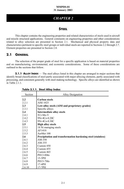
Table 2.1.1. Steel Alloy Index<br />
STEEL<br />
This chapter contains the engineering properties and related characteristics of <strong>steel</strong>s used in aircraft<br />
and missile structural applications. General comments on engineering properties and other considerations<br />
related to alloy selection are presented in Section 2.1. Mechanical and physical property data and<br />
characteristics pertinent to specific <strong>steel</strong> groups or individual <strong>steel</strong>s are reported in Sections 2.2 through 2.7.<br />
Element properties are presented in Section 2.8.<br />
2.1 GENERAL<br />
The selection of the proper grade of <strong>steel</strong> for a specific application is based on material properties<br />
and on manufacturing, environmental, and economic considerations. Some of these considerations are<br />
outlined in the sections that follow.<br />
2.1.1 ALLOY INDEX — The <strong>steel</strong> alloys listed in this chapter are arranged in major sections that<br />
identify broad classifications of <strong>steel</strong> partly associated with major alloying elements, partly associated with<br />
processing, and consistent generally with <strong>steel</strong>-making technology. Specific alloys are identified as shown<br />
in Table 2.1.1.<br />
Section<br />
2.2<br />
2.2.1<br />
2.3<br />
2.3.1<br />
2.4<br />
2.4.1<br />
2.4.2<br />
2.4.3<br />
2.5<br />
2.5.1<br />
2.5.2<br />
2.5.3<br />
2.6<br />
2.6.1<br />
2.6.2<br />
2.6.3<br />
2.6.4<br />
2.6.5<br />
2.6.6<br />
2.6.7<br />
2.6.8<br />
2.6.9<br />
2.6.10<br />
Alloy Designation<br />
Carbon <strong>steel</strong>s<br />
AISI 1025<br />
Low-alloy <strong>steel</strong>s (AISI and proprietary grades)<br />
Specific alloys<br />
Intermediate alloy <strong>steel</strong>s<br />
5Cr-Mo-V<br />
9Ni-4Co-0.20C<br />
9Ni-4Co-0.30C<br />
High alloy <strong>steel</strong>s<br />
18 Ni maraging <strong>steel</strong>s<br />
AF1410<br />
AerMet 100<br />
Precipitation and transformation hardening <strong>steel</strong> (stainless)<br />
AM-350<br />
AM-355<br />
Custom 450<br />
Custom 455<br />
Custom 465<br />
PH13-8Mo<br />
15-5PH<br />
PH15-7Mo<br />
17-4PH<br />
17-7PH<br />
2-1
MMPDS-01<br />
31 January 2003<br />
Table 2.1.1(Continued). Steel Alloy Index<br />
2.7<br />
2.7.1<br />
Section<br />
Alloy Designation<br />
Austenitic stainless <strong>steel</strong>s<br />
AISI 301 and Related 300 Series Stainless Steels<br />
2.1.2 MATERIAL PROPERTIES — One of the major factors contributing to the general utility of <strong>steel</strong>s<br />
is the wide range of mechanical properties which can be obtained by heat treatment. For example, softness<br />
and good ductility may be required during fabrication of a part and very high strength during its service life.<br />
Both sets of properties are obtainable in the same material.<br />
All <strong>steel</strong>s can be softened to a greater or lesser degree by annealing, depending on the chemical<br />
composition of the specific <strong>steel</strong>. Annealing is achieved by heating the <strong>steel</strong> to an appropriate temperature,<br />
holding, then cooling it at the proper rate.<br />
Likewise, <strong>steel</strong>s can be hardened or strengthened by means of cold working, heat treating, or a combination<br />
of these.<br />
Cold working is the method used to strengthen both the low-carbon unalloyed <strong>steel</strong>s and the highly<br />
alloyed austenitic stainless <strong>steel</strong>s. Only moderately high strength levels can be attained in the former, but the<br />
latter can be cold rolled to quite high strength levels, or “tempers”. These are commonly supplied to specified<br />
minimum strength levels.<br />
Heat treating is the principal method for strengthening the remainder of the <strong>steel</strong>s (the low-carbon<br />
<strong>steel</strong>s and the austenitic <strong>steel</strong>s cannot be strengthened by heat treatment). The heat treatment of <strong>steel</strong> may<br />
be of three types: martensitic hardening, age hardening, and austempering. Carbon and alloy <strong>steel</strong>s are<br />
martensitic-hardened by heating to a high temperature, or “austenitizing”, and cooling at a recommended rate,<br />
often by quenching in oil or water. This is followed by “tempering”, which consists of reheating to an<br />
intermediate temperature to relieve internal stresses and to improve toughness.<br />
The maximum hardness of carbon and alloy <strong>steel</strong>s, quenched rapidly to avoid the nose of the<br />
isothermal transformation curve, is a function in general of the alloy content, particularly the carbon content.<br />
Both the maximum thickness for complete hardening or the depth to which an alloy will harden under<br />
specific cooling conditions, and the distribution of hardness can be used as a measure of a material’s<br />
hardenability.<br />
A relatively new class of <strong>steel</strong>s is strengthened by age hardening. This heat treatment is designed<br />
to dissolve certain constituents in the <strong>steel</strong>, then precipitate them in some preferred particle size and<br />
distribution. Since both the martensitic hardening and the age-hardening treatments are relatively complex,<br />
specific details are presented for individual <strong>steel</strong>s elsewhere in this chapter.<br />
Recently, special combinations of working and heat treating have been employed to further enhance<br />
the mechanical properties of certain <strong>steel</strong>s. At the present time, the use of these specialized treatments is not<br />
widespread.<br />
Another method of heat treatment for <strong>steel</strong>s is austempering. In this process, ferrous <strong>steel</strong>s are<br />
austenitized, quenched rapidly to avoid transformation of the austenite to a temperature below the pearlite<br />
2-2
MMPDS-01<br />
31 January 2003<br />
and above the martensite formation ranges, allowed to transform isothermally at that temperature to a<br />
completely bainitic structure, and finally cooled to room temperature. The purpose of austempering is to<br />
obtain increased ductility or notch toughness at high hardness levels, or to decrease the likelihood of cracking<br />
and distortion that might occur in conventional quenching and tempering.<br />
2.1.2.1 Mechanical Properties —<br />
2.1.2.1.1 Strength (Tension, Compression, Shear, Bearing) — The strength properties presented<br />
are those used in structural design. The room-temperature properties are shown in tables following<br />
the comments for individual <strong>steel</strong>s. The variations in strength properties with temperature are presented<br />
graphically as percentages of the corresponding room-temperature strength property, also described in<br />
Section 9.3.1 and associated subsections. These strength properties may be reduced appreciably by prolonged<br />
exposure at elevated temperatures.<br />
The strength of <strong>steel</strong>s is temperature-dependent, decreasing with increasing temperature. In addition,<br />
<strong>steel</strong>s are strain rate-sensitive above about 600 to 800EF, particularly at temperatures at which creep occurs.<br />
At lower strain rates, both yield and ultimate strengths decrease.<br />
The modulus of elasticity is also temperature-dependent and, when measured by the slope of the<br />
stress-strain curve, it appears to be strain rate-sensitive at elevated temperatures because of creep during<br />
loading. However, on loading or unloading at high rates of strain, the modulus approaches the value<br />
measured by dynamic techniques.<br />
Steel bars, billets, forgings, and thick plates, especially when heat treated to high strength levels,<br />
exhibit variations in mechanical properties with location and direction. In particular, elongation, reduction<br />
of area, toughness, and notched strength are likely to be lower in either of the transverse directions than in<br />
the longitudinal direction. This lower ductility and/or toughness results both from the fibering caused by the<br />
metal flow and from nonmetallic inclusions which tend to be aligned with the direction of primary flow. Such<br />
anisotropy is independent of the depth-of-hardening considerations discussed elsewhere. It can be minimized<br />
by careful control of melting practices (including degassing and vacuum-arc remelting) and of hot-working<br />
practices. In applications where transverse properties are critical, requirements should be discussed with the<br />
<strong>steel</strong> supplier and properties in critical locations should be substantiated by appropriate testing.<br />
2.1.2.1.2 Elongation — The elongation values presented in this chapter apply in both the longitudinal<br />
and long transverse directions, unless otherwise noted. Elongation in the short transverse (thickness)<br />
direction may be lower than the values shown.<br />
2.1.2.1.3 Fracture Toughness — Steels (as well as certain other metals), when processed to<br />
obtain high strength, or when tempered or aged within certain critical temperature ranges, may become more<br />
sensitive to the presence of small flaws. Thus, as discussed in Section 1.4.12, the usefulness of high-strength<br />
<strong>steel</strong>s for certain applications is largely dependent on their toughness. It is generally noted that the fracture<br />
toughness of a given alloy product decreases relative to increase in the yield strength. The designer is cautioned<br />
that the propensity for brittle fracture must be considered in the application of high-strength alloys for<br />
the purpose of increased structural efficiency.<br />
Minimum, average, and maximum values, as well as coefficient of variation of plane-strain fracture<br />
toughness for several <strong>steel</strong> alloys, are presented in Table 2.1.2.1.3. These values are presented as indicative<br />
information and do not have the statistical reliability of room-temperature mechanical properties. Data<br />
showing the effect of temperature are presented in the respective alloy sections where the information is<br />
available.<br />
2-3
Table 2.1.2.1.3. Values of Room Temperature Plane-Strain Fracture Toughness of Steel Alloys a<br />
Alloy<br />
Heat Treat<br />
Condition<br />
Product<br />
Form<br />
Orientation<br />
b<br />
Yield<br />
Strength<br />
Range,<br />
ksi<br />
Product<br />
Thickness<br />
Range,<br />
inches<br />
Number<br />
of<br />
Sources<br />
Sample<br />
Size<br />
Specimen<br />
Thickness<br />
Range,<br />
inches<br />
K IC , ksi /in.<br />
Max. Avg. Min.<br />
Coefficient<br />
of Variation<br />
AerMet 100 Anneal, HT to 280ksi Bar L-R 236-281 2.75-10 1 183 1 146 121 100 7.9<br />
AerMet 100 Anneal, HT to 280ksi Bar C-R 223-273 2.75-10 1 156 1 137 112 90 8.5<br />
AerMet 100 Anneal, HT to 290ksi Bar L-R 251-265 3-10 1 29 1 110 99 88 6.5<br />
AerMet 100 Anneal, HT to 290ksi Bar C-R 250-268 3-10 1 24 1 101 88 73 9.7<br />
Custom 465 H950 Bar L-R c 229-249 3-12 1 40 1-1.5 104 89 76 7.4<br />
Custom 465 H950 Bar R-L c 231-246 3-12 1 40 1-1.5 94 82 73 6.4<br />
Custom 465 H1000 Bar L-R c 212-227 3-12 1 40 1-1.5 131 120 108 5.2<br />
Custom 465 H1000 Bar R-L c 212-225 3-12 1 40 1-1.5 118 109 100 3.7<br />
2-4<br />
D6AC<br />
D6AC<br />
D6AC<br />
1650EF, Aus-Bay<br />
Quench 975EF, SQ<br />
375EF, 1000EF 2 + 2<br />
1650EF, Aus-Bay<br />
Quench 975EF, SQ<br />
400EF, 1000EF 2 + 2<br />
1650EF, Aus-Bay<br />
Quench 975EF, SQ<br />
400EF, 1000EF 2 + 2<br />
Plate L-T 217 1.5 1 19 0.6 88 62 40 22.5<br />
Plate L-T 217 0.8 1 103 0.6-0.8 92 64 44 18.9<br />
Forging L-T 214 0.8-1.5 1 53 0.6-0.8 96 66 39 18.6<br />
MMPDS-01<br />
31 January 2003<br />
D6AC<br />
1700EF, Aus-Bay<br />
Quench 975EF, OQ<br />
140EF, 1000EF 2 + 2<br />
Plate L-T 217 0.8-1.5 1 30 0.6-0.8 101 92 64 8.9<br />
D6AC<br />
1700EF, Aus-Bay<br />
Quench 975EF, OQ<br />
140EF, 1000EF 2 + 2<br />
Forging L-T 214 0.8-1.5 1 34 0.7 109 95 81 6.7<br />
9Ni-4Co-.20C Quench and Temper Hand<br />
Forging<br />
L-T 185-192 3.0 2 27 1.0-2.0 147 129 107 8.3<br />
9Ni-4Co-.20C<br />
1650EF, 1-2 Hr, AC,<br />
1525EF, 1-2 Hr, OQ,<br />
-100EF, Temp<br />
Forging L-T 186-192 3.0-4.0 3 17 1.5-2.0 147 134 120 8.5<br />
PH13-8Mo H1000 Forging L-T 205-212 4.0-8.0 3 12 0.7-2.0 104 90 49 21.5<br />
a These values are for information only.<br />
b Refer to Figures 1.4.12.3(a) and 1.4.12.3(b) for definition of symbols.<br />
c L-R also includes some L-T, R-L also includes some T-L.
MMPDS-01<br />
31 January 2003<br />
2.1.2.1.4 Stress-Strain Relationships — The stress-strain relationships presented in this chapter<br />
are prepared as described in Section 9.3.2.<br />
2.1.2.1.5 Fatigue — Axial-load fatigue data on unnotched and notched specimens of various <strong>steel</strong>s<br />
at room temperature and at other temperatures are shown as S/N curves in the appropriate section. Surface<br />
finish, surface finishing procedures, metallurgical effects from heat treatment, environment and other factors<br />
influence fatigue behavior. Specific details on these conditions are presented as correlative information for<br />
the S/N curve.<br />
2.1.2.2 Physical Properties — The physical properties (ω, C, K, and α) of <strong>steel</strong>s may be considered<br />
to apply to all forms and heat treatments unless otherwise indicated.<br />
2.1.3 ENVIRONMENTAL CONSIDERATIONS — The effects of exposure to environments such as<br />
stress, temperature, atmosphere, and corrosive media are reported for various <strong>steel</strong>s. Fracture toughness of<br />
high-strength <strong>steel</strong>s and the growth of cracks by fatigue may be detrimentally influenced by humid air and<br />
by the presence of water or saline solutions. Some alleviation may be achieved by heat treatment and all<br />
high-strength <strong>steel</strong>s are not similarly affected.<br />
In general, these comments apply to <strong>steel</strong>s in their usual finished surface condition, without surface<br />
protection. It should be noted that there are available a number of heat-resistant paints, platings, and other<br />
surface coatings that are employed either to improve oxidation resistance at elevated temperature or to afford<br />
protection against corrosion by specific media. In employing electrolytic platings, special consideration<br />
should be given to the removal of hydrogen by suitable baking. Failure to do so may result in lowered<br />
fracture toughness or embrittlement.<br />
2-5
MMPDS-01<br />
31 January 2003<br />
2.2 CARBON STEELS<br />
2.2.0 COMMENTS ON CARBON STEELS<br />
2.2.0.1 Metallurgical Considerations — Carbon <strong>steel</strong>s are those <strong>steel</strong>s containing carbon up<br />
to about 1 percent and only residual quantities of other elements except those added for deoxidation.<br />
The strength that carbon <strong>steel</strong>s are capable of achieving is determined by carbon content and, to a<br />
much lesser extent, by the content of the residual elements. Through cold working or proper choice of heat<br />
treatments, these <strong>steel</strong>s can be made to exhibit a wide range of strength properties.<br />
The finish conditions most generally specified for carbon <strong>steel</strong>s include hot-rolled, cold-rolled, colddrawn,<br />
normalized, annealed, spheroidized, stress-relieved, and quenched-and-tempered. In addition, the lowcarbon<br />
grades (up to 0.25 percent C) may be carburized to obtain high surface hardness and wear resistance<br />
with a tough core. Likewise, the higher carbon grades are amenable to selective flame hardening to obtain<br />
desired combinations of properties.<br />
2.2.0.2 Manufacturing Considerations —<br />
Forging — All of the carbon <strong>steel</strong>s exhibit excellent forgeability in the austenitic state provided the<br />
proper forging temperatures are used. As the carbon content is increased, the maximum forging temperature<br />
is decreased. At high temperatures, these <strong>steel</strong>s are soft and ductile and exhibit little or no tendency to work<br />
harden. The resulfurized grades (free-machining <strong>steel</strong>s) exhibit a tendency to rupture when deformed in<br />
certain high-temperature ranges. Close control of forging temperatures is required.<br />
Cold Forming — The very low-carbon grades have excellent cold-forming characteristics when in<br />
the annealed or normalized conditions. Medium-carbon grades show progressively poorer formability with<br />
higher carbon content, and more frequent annealing is required. The high-carbon grades require special<br />
softening treatments for cold forming. Many carbon <strong>steel</strong>s are embrittled by warm working or prolonged<br />
exposure in the temperature range from 300 to 700EF.<br />
Machining — The low-carbon grades (0.30 percent C and less) are soft and gummy in the annealed<br />
condition and are preferably machined in the cold-worked or the normalized condition. Medium-carbon (0.30<br />
to 0.50 percent C) grades are best machined in the annealed condition, and high-carbon grades (0.50 to 0.90<br />
percent C) in the spheroidized condition. Finish machining must often be done in the fully heat-treated<br />
condition for dimensional accuracy. The resulfurized grades are well known for their good machinability.<br />
Nearly all carbon <strong>steel</strong>s are now available with 0.15 to 0.35 percent lead, added to improve machinability.<br />
However, resulfurized and leaded <strong>steel</strong>s are not generally recommended for highly stressed aircraft and<br />
missile parts because of a drastic reduction in transverse properties.<br />
Welding — The low-carbon grades are readily welded or brazed by all techniques. The mediumcarbon<br />
grades are also readily weldable but may require preheating and postwelding heat treatment. The<br />
high-carbon grades are difficult to weld. Preheating and postwelding heat treatment are usually mandatory<br />
for the latter, and special care must be taken to avoid overheating. Furnace brazing has been used<br />
successfully with all grades.<br />
Heat Treatment — Due to the poor oxidation resistance of carbon <strong>steel</strong>s, protective atmospheres must<br />
be employed during heat treatment if scaling of the surface cannot be tolerated. Also, these <strong>steel</strong>s are subject<br />
to decarburization at elevated temperatures and, where surface carbon content is critical, should be heated<br />
in reducing atmospheres.<br />
2-6
MMPDS-01<br />
31 January 2003<br />
2.2.0.3 Environmental Considerations — Carbon <strong>steel</strong>s have poor oxidation resistance above<br />
about 900 to 1000EF. Strength and oxidation-resistance criteria generally preclude the use of carbon <strong>steel</strong>s<br />
above 900EF.<br />
Carbon <strong>steel</strong>s may undergo an abrupt transition from ductile to brittle behavior. This transition<br />
temperature varies widely for different carbon <strong>steel</strong>s depending on many factors. Cautions should be<br />
exercised in the application of carbon <strong>steel</strong>s to assure that the transition temperature of the selected alloy is<br />
below the service temperature. Additional information is contained in References 2.2.0.3(a) and (b).<br />
The corrosion resistance of carbon <strong>steel</strong>s is relatively poor; clean surfaces rust rapidly in moist<br />
atmospheres. Simple oil film protection is adequate for normal handling. For aerospace applications, the<br />
carbon <strong>steel</strong>s are usually plated to provide adequate corrosion protection.<br />
2.2.1 AISI 1025<br />
2.2.1.0 Comments and Properties — AISI 1025 is an excellent general purpose <strong>steel</strong> for the<br />
majority of shop requirements, including jigs, fixtures, prototype mockups, low torque shafting, and other<br />
applications. It is not generally classed as an airframe structural <strong>steel</strong>. However, it is available in aircraft<br />
quality as well as commercial quality.<br />
Manufacturing Considerations — Cold-finished flat-rolled products are supplied principally where<br />
maximum strength, good surface finish, or close tolerance is desirable. Reasonably good forming properties<br />
are found in AISI 1025. The machinability of bar stock is rated next to these sulfurized types of<br />
free-machining <strong>steel</strong>s, but the resulting surface finish is poorer.<br />
Specifications and Properties — Material specifications for AISI 1025 <strong>steel</strong> are presented in Table<br />
2.2.1.0(a). The room-temperature mechanical and physical properties are shown in Table 2.2.1.0(b). The<br />
effect of temperature on thermal expansion is shown in Figure 2.2.1.0.<br />
Table 2.2.1.0(a). Material Specifications for<br />
AISI 1025 Carbon Steel<br />
Specification<br />
Form<br />
ASTM A 108<br />
Bar<br />
AMS 5075<br />
Seamless tubing<br />
AMS-T-5066 a<br />
Tubing<br />
AMS 5077<br />
Tubing<br />
AMS 5046<br />
Sheet, strip, and plate<br />
AMS-S-7952<br />
Sheet and strip<br />
a Noncurrent specification<br />
2-7
MMPDS-01<br />
31 January 2003<br />
Table 2.2.1.0(b). Design Mechanical and Physical Properties of AISI 1025 Carbon Steel<br />
Specification ...........<br />
AMS 5046 and AMS 5075, AMS 5077<br />
AMS-S-7952 and AMS-T-5066 a ASTM A 108<br />
Form.................. Sheet, strip, and plate Tubing Bar<br />
Condition .............. Annealed Normalized All<br />
Thickness, in. .......... ... ... ...<br />
Basis.................. S S S b<br />
Mechanical Properties:<br />
F tu , ksi:<br />
L .................. 55 55 55<br />
LT ................. 55 55 55<br />
ST ................. ... ... 55<br />
F ty , ksi:<br />
L .................. 36 36 36<br />
LT ................. 36 36 36<br />
ST ................. ... ... 36<br />
F cy , ksi:<br />
L .................. 36 36 36<br />
LT ................. 36 36 36<br />
ST ................. ... ... 36<br />
F su , ksi ............... 35 35 35<br />
F bru , ksi:<br />
(e/D = 1.5)........... ... ... ...<br />
(e/D = 2.0)........... 90 90 90<br />
F bry , ksi:<br />
(e/D = 1.5)........... ... ... ...<br />
(e/D = 2.0)........... ... ... ...<br />
e, percent:<br />
L .................. ... c c<br />
LT ................. c ... ...<br />
E, 10 3 ksi ............. 29.0<br />
E c , 10 3 ksi ............ 29.0<br />
G, 10 3 ksi............. 11.0<br />
µ ................... 0.32<br />
Physical Properties:<br />
ω, lb/in. 3 ............. 0.284<br />
C, Btu/(lb)(EF) ........ 0.116 (122 to 212EF)<br />
K, Btu/[(hr)(ft 2 )(EF)/ft] . . 30.0 (at 32EF)<br />
α, 10 -6 in./in./EF ........ See Figure 2.2.1.0<br />
a Noncurrent specification.<br />
b Design values are applicable only to parts for which the indicated F tu has been substantiated by adequate quality control testing.<br />
c See applicable specification for variation in minimum elongation with ultimate strength.<br />
2-8
MMPDS-01<br />
31 January 2003<br />
9 α, - Between 70 F and indicated temperature<br />
α, 10-6 in./in./F<br />
8<br />
7<br />
6<br />
5<br />
0 200 400 600 800 1000 1200 1400 1600<br />
Temperature, F<br />
Figure 2.2.1.0. Effect of temperature on the thermal expansion of 1025 <strong>steel</strong>.<br />
2-9
MMPDS-01<br />
31 January 2003<br />
2.3 LOW-ALLOY STEELS (AISI GRADES AND PROPRIETARY GRADES)<br />
2.3.0 COMMENTS ON LOW-ALLOY STEELS (AISI AND PROPRIETARY GRADES)<br />
2.3.0.1 Metallurgical Considerations — The AISI or SAE alloy <strong>steel</strong>s contain, in addition<br />
to carbon, up to about 1 percent (up to 0.5 percent for most airframe applications) additions of various<br />
alloying elements to improve their strength, depth of hardening, toughness, or other properties of interest.<br />
Generally, alloy <strong>steel</strong>s have better strength-to-weight ratios than carbon <strong>steel</strong>s and are somewhat higher in<br />
cost on a weight, but not necessarily strength, basis. Their applications in airframes include landing-gear<br />
components, shafts, gears, and other parts requiring high strength, through hardening, or toughness.<br />
Some alloy <strong>steel</strong>s are identified by the AISI four-digit system of numbers. The first two digits<br />
indicate the alloy group and the last two the approximate carbon content in hundredths of a percent. The<br />
alloying elements used in these <strong>steel</strong>s include manganese, silicon, nickel, chromium, molybdenum, vanadium,<br />
and boron. Other <strong>steel</strong>s in this section are proprietary <strong>steel</strong>s which may be modifications of the AISI grades.<br />
The alloying additions in these <strong>steel</strong>s may provide deeper hardening, higher strength and toughness.<br />
These <strong>steel</strong>s are available in a variety of finish conditions, ranging from hot- or cold-rolled to<br />
quenched-and-tempered. They are generally heat treated before use to develop the desired properties. Some<br />
<strong>steel</strong>s in this group are carburized, then heat treated to produce a combination of high surface hardness and<br />
good core toughness.<br />
2.3.0.2 Manufacturing Conditions —<br />
Forging — The alloy <strong>steel</strong>s are only slightly more difficult to forge than carbon <strong>steel</strong>s. However,<br />
maximum recommended forging temperatures are generally about 50EF lower than for carbon <strong>steel</strong>s of the<br />
same carbon content. Slower heating rates, shorter soaking period, and slower cooling rates are also required<br />
for alloy <strong>steel</strong>s.<br />
Cold Forming — The alloy <strong>steel</strong>s are usually formed in the annealed condition. Their formability<br />
depends mainly on the carbon content and is generally slightly poorer than for unalloyed <strong>steel</strong>s of the same<br />
carbon content. Little cold forming is done on these <strong>steel</strong>s in the heat-treated condition because of their high<br />
strength and limited ductility.<br />
Machining — The alloy <strong>steel</strong>s are generally harder than unalloyed <strong>steel</strong>s of the same carbon content.<br />
As a consequence, the low-carbon alloy <strong>steel</strong>s are somewhat easier to finish machine than their counterparts<br />
in the carbon <strong>steel</strong>s. It is usually desirable to finish machine the carburizing and through-hardening grades<br />
in the final heat-treated condition for better dimensional accuracy. This often leads to two steps in machining:<br />
rough machining in the annealed or hot-finished condition, then finish machining after heat treating. The<br />
latter operation, because of the relatively high hardness of the material, necessitates the use of sharp, welldesigned,<br />
high-speed <strong>steel</strong> cutting tools, proper feeds, speeds, and a generous supply of coolant. Mediumand<br />
high-carbon grades are usually spheroidized for optimum machinability and, after heat treatment, may<br />
be finished by grinding. Many of the alloy <strong>steel</strong>s are available with added sulfur or lead for improved<br />
machinability. However, resulfurized and leaded <strong>steel</strong>s are not recommended for highly stressed aircraft and<br />
missile parts, because of drastic reductions in transverse properties.<br />
Welding — The low-carbon grades are readily welded or brazed by all techniques. Alloy welding<br />
rods comparable in strength to the base metal are used, and moderate preheating (200 to 600EF) is usually<br />
necessary. At higher carbon levels, higher preheating temperatures, and often postwelding stress relieving,<br />
are required. Certain alloy <strong>steel</strong>s can be welded without loss of strength in the heat-affected zone provided<br />
that the welding heat input is carefully controlled. If the composition and strength level are such that the<br />
strength of the welded joint is reduced, the strength of the joint may be restored by heat treatment after<br />
welding.<br />
2-10
MMPDS-01<br />
31 January 2003<br />
Heat Treatment — For the low alloy <strong>steel</strong>s, there are various heat treatment procedures that can be<br />
applied to a particular alloy to achieve any one of a number of specific mechanical (for example tensile)<br />
properties. Within this chapter, there are mechanical properties for three thermal processing conditions:<br />
annealed, normalized, and quenched and tempered. The specific details of these three thermal processing<br />
conditions are reviewed in Reference 2.3.0.2.5. In general, the annealed condition is achieved by heating to<br />
a suitable temperature and holding for a specified period of time. Annealing generally softens the material,<br />
producing the lowest mechanical properties. The normalized condition is achieved by holding to a slightly<br />
higher temperature than annealing, but for a shorter period of time. The purpose of normalizing varies<br />
depending on the desired properties; it can be used to increase or decrease mechanical properties. The<br />
quenched and tempered condition, discussed in more detail below, is used to produce the highest mechanical<br />
properties while providing relatively high toughness. The mechanical properties for these three processing<br />
conditions for specific <strong>steel</strong>s are as shown in Tables 2.3.1.0(c), (f), and (g).<br />
Maximum hardness in these <strong>steel</strong>s is obtained in the as-quenched condition, but toughness and<br />
ductility in this condition are comparatively low. By means of tempering, their toughness is improved,<br />
usually accompanied by a decrease in strength and hardness. In general, tempering temperatures to achieve<br />
very high strength should be avoided when toughness is an important consideration.<br />
In addition, these <strong>steel</strong>s may be embrittled by tempering or by prolonged exposure under stress within<br />
the “blue brittle” range (approximately 500 to 700EF). Strength levels that necessitate tempering within this<br />
range should be avoided.<br />
The mechanical properties presented in this chapter represent <strong>steel</strong>s heat treated to produce a<br />
quenched structure containing 90 percent martensite at the center and tempered to the desired F tu level. This<br />
degree of through hardening is necessary (regardless of strength level) to insure the attainment of reasonably<br />
uniform mechanical properties throughout the cross section of the heat-treated part. The maximum diameter<br />
of round bars of various alloy <strong>steel</strong>s capable of being through hardened consistently are given in Table<br />
2.3.0.2. Limiting dimensions for common shapes other than round are determined by means of the<br />
“equivalent round” concept in Figure 2.3.0.2. This concept is essentially a correlation between the significant<br />
dimensions of a particular shape and the diameter of a round bar, assuming in each instance that the material,<br />
heat treatment, and the mechanical properties at the centers of both the respective shape and the equivalent<br />
round are substantially the same.<br />
For the quenched and tempered condition, a large range of mechanical property values can be<br />
achieved as indicated in Table 2.3.0.2. Various quench media (rates), tempering temperatures, and times can<br />
be employed allowing any number of processing routes to achieve these values. As a result of these<br />
processing routes, there are a large range of mechanical properties that can be obtained for a specific alloy.<br />
Therefore, the properties of a <strong>steel</strong> can be tailored to meet the needs for a specific component/application.<br />
Because of the potential for several different processing methods for these three conditions, the MIL,<br />
Federal, and AMS specifications do not always contain minimum mechanical property values (S-basis). They<br />
may contain minimum mechanical property values for one specific quenched and tempered condition. Those<br />
specifications cited in this Handbook that do not contain mechanical properties are identified with a footnote<br />
in Tables 2.3.1.0(a) and (b). The possible mechanical properties for these alloys covered in the specifications<br />
for the normalized, and quenched and tempered conditions in Table 2.3.0.2 are presented in Tables 2.3.1.0<br />
(g 1 ) and (g 2 ). Users must rely on their own in-house specifications or appropriate industry specifications to<br />
validate that the required strength was achieved. Therefore, no statistical basis (A, B, S) for these values are<br />
indicated in Tables 2.3.1.0 (g 1 ) and (g 2 ).<br />
2-11
MMPDS-01<br />
31 January 2003<br />
Table 2.3.0.2. Maximum Round Diameters for Low-Alloy Steel Bars (Through<br />
Hardening to at Least 90 Percent Martensite at Center)<br />
Maximum Diameter of Round or Equivalent Round, in. a<br />
F tu , ksi 0.5 0.8 1.0 1.7 2.5 3.5 5.0<br />
270 & 280 . . . . . . . . . . . . . . . . . . 300M c<br />
260 . . . . . . . . . AISI 4340 b AISI 4340 c AISI 4340 d . . .<br />
220 . . . . . . . . . AMS Grades b,e AMS Grades c,e D6AC b D6AC c<br />
200 . . . AISI 8740 AISI 4140 AISI 4340 b<br />
AMS Grades b,e<br />
AISI 4340 c<br />
AMS Grades c,e AISI 4340 d D6AC c<br />
#180 AISI 4130<br />
and 8630<br />
AISI 8735<br />
4135 and 8740<br />
AISI 4140<br />
AISI 4340 b<br />
AMS Grades b,e<br />
AISI 4340 c<br />
AMS Grades c,e<br />
AISI 4340 d<br />
D6AC b<br />
D6AC c<br />
a This table indicates the maximum diameters to which these <strong>steel</strong>s may be through hardened consistently by quenching as<br />
indicated. Any <strong>steel</strong>s in this table may be used at diameters less than those indicated. The use of <strong>steel</strong>s at diameters greater<br />
than those indicated should be based on hardenability data for specific heats of <strong>steel</strong>.<br />
b Quenched in molten salt at desired tempering temperature (“martempering”).<br />
c Quenched in oil at a flow rate of 200 feet per minute.<br />
d Quenched in water at a flow rate of 200 feet per minute.<br />
e 4330V, 4335V, and Hy-Tuf.<br />
2-12
MMPDS-01<br />
31 January 2003<br />
Figure 2.3.0.2. Correlation between significant dimensions of common shapes other<br />
than round, and the diameters of round bars.<br />
2-13
MMPDS-01<br />
31 January 2003<br />
2.3.0.3 Environmental Considerations — Alloy <strong>steel</strong>s containing chromium or high<br />
percentages of silicon have somewhat better oxidation resistance than the carbon or other alloy <strong>steel</strong>s.<br />
Elevated-temperature strength for the alloy <strong>steel</strong>s is also higher than that of corresponding carbon <strong>steel</strong>s. The<br />
mechanical properties of all alloy <strong>steel</strong>s in the heat-treated condition are affected by extended exposure to<br />
temperatures near or above the temperature at which they were tempered. The limiting temperatures to which<br />
each alloy may be exposed for no longer than approximately 1 hour per inch of thickness or approximately<br />
one-half hour for thicknesses under one-half inch without a reduction in strength occurring are listed in Table<br />
2.3.0.3. These values are approximately 100EF below typical tempering temperatures used to achieve the<br />
designated strength levels.<br />
Table 2.3.0.3. Temperature Exposure Limits for Low-Alloy Steels<br />
Exposure Limit, EF<br />
F tu , ksi 125 150 180 200 220 260 270 & 280<br />
Alloy:<br />
AISI 4130 and 925 775 575 . . . . . . . . . . . .<br />
8630<br />
AISI 4140 and 1025 875 725 625 . . . . . . . . .<br />
8740<br />
AISI 4340 1100 950 800 700 . . . 350 . . .<br />
AISI 4135 and 975 825 675 . . . . . . . . . . . .<br />
8735<br />
D6AC 1150 1075 1000 950 900 500 . . .<br />
Hy-Tuf 875 750 650 550 450 . . . . . .<br />
4330V 925 850 775 700 500 . . . . . .<br />
4335V 975 875 775 700 500 . . . . . .<br />
300M . . . . . . . . . . . . . . . . . . 475<br />
a<br />
Quenched and tempered to F tu indicated. If the material is exposed to temperatures exceeding those listed,<br />
a reduction in strength is likely to occur.<br />
Low-alloy <strong>steel</strong>s may undergo a transition from ductile to brittle behavior at low temperatures. This<br />
transition temperature varies widely for different alloys. Caution should be exercised in the application of<br />
low-alloy <strong>steel</strong>s at temperatures below -100EF. For use at a temperature below -100EF, an alloy with a<br />
transition temperature below the service temperature should be selected. For low temperatures, the <strong>steel</strong><br />
should be heat treated to a tempered martensitic condition for maximum toughness.<br />
Heat-treated alloy <strong>steel</strong>s have better notch toughness than carbon <strong>steel</strong>s at equivalent strength levels.<br />
The decrease in notch toughness is less pronounced and occurs at lower temperatures. Heat-treated alloy<br />
<strong>steel</strong>s may be useful for subzero applications, depending on their alloy content and heat treatment. Heat<br />
treating to strength levels higher than 150 ksi F ty may decrease notch toughness.<br />
The corrosion properties of the AISI alloy <strong>steel</strong>s are comparable to the plain carbon <strong>steel</strong>s.<br />
2-14
MMPDS-01<br />
31 January 2003<br />
2.3.1 SPECIFIC ALLOYS<br />
2.3.1.0 Comments and Properties — AISI 4130 is a chromium-molybdenum <strong>steel</strong> that is in<br />
general use due to its well-established heat-treating practices and processing techniques. It is available in all<br />
sizes of sheet, plate, and tubing. Bar stock of this material is also used for small forgings under one-half inch<br />
in thickness. AISI 4135, a slightly higher carbon version of AISI 4130, is available in sheet, plate, and<br />
tubing.<br />
AISI 4140 is a chromium-molybdenum <strong>steel</strong> that can be heat treated in thicker sections and to higher<br />
strength levels than AISI 4130. This <strong>steel</strong> is generally used for structural machined and forged parts one-half<br />
inch and over in thickness. It can be welded but it is more difficult to weld than the lower carbon grade AISI<br />
4130.<br />
AISI 4340 is a nickel-chromium-molybdenum <strong>steel</strong> that can be heat treated in thicker sections and<br />
to higher strength levels than AISI 4140.<br />
AISI 8630, 8735, and 8740 are nickel-chromium-molybdenum <strong>steel</strong>s that are considered alternates<br />
to AISI 4130, 4135, and 4140, respectively.<br />
There are a number of <strong>steel</strong>s available with compositions that represent modifications to the AISI<br />
grades described above. Four of the <strong>steel</strong>s that have been used rather extensively at F tu = 220 ksi are D6AC,<br />
Hy-Tuf, 4330V, and 4335V. It should be noted that this strength level is not used for AISI 4340 due to<br />
embrittlement encountered during tempering in the range of 500 to 700EF. In addition, AISI 4340 and 300M<br />
are utilized at strength levels of F tu = 260 ksi or higher. The alloys, AISI 4340, D6AC, 4330V, 4335V, and<br />
300M, are available in the consumable electrode melted grade. Material specifications for these <strong>steel</strong>s are<br />
presented in Tables 2.3.1.0(a) and (b).<br />
The room-temperature mechanical and physical properties for these <strong>steel</strong>s are presented in<br />
Tables 2.3.1.0(c) through 2.3.1.0(g). Mechanical properties for heat-treated materials are valid only for <strong>steel</strong><br />
heat treated to produce a quenched structure containing 90 percent or more martensite at the center. Figure<br />
2.3.1.0 contains elevated temperature curves for the physical properties of AISI 4130 and AISI 4340<br />
<strong>steel</strong>s.<br />
2.3.1.1 AISI Low-Alloy Steels — Elevated temperature curves for heat-treated AISI low-alloy<br />
<strong>steel</strong>s are presented in Figures 2.3.1.1.1 through 2.3.1.1.4. These curves are considered valid for each of these<br />
<strong>steel</strong>s in each heat-treated condition but only up to the maximum temperatures listed in Table 2.3.0.1(b).<br />
2.3.1.2 AISI 4130 and 8630 Steels — Typical stress-strain and tangent-modulus curves for<br />
AISI 8630 are shown in Figures 2.3.1.2.6(a) through (c). Best-fit S/N curves for AISI 4130 <strong>steel</strong> are presented<br />
in Figures 2.3.1.2.8(a) through (h).<br />
2.3.1.3 AISI 4340 Steel — Typical stress-strain and tangent-modulus curves for AISI 4340 are<br />
shown in Figures 2.3.1.3.6(a) through (c). Typical biaxial stress-strain curves and yield-stress envelopes for<br />
AISI 4340 alloy <strong>steel</strong> are presented in Figures 2.3.1.3.6(d) through (g). Best-fit S/N curves for AISI 4340<br />
are presented in Figures 2.3.1.3.8(a) through (o).<br />
2.3.1.4 300M Steel — Best-fit S/N curves for 300M <strong>steel</strong> are presented in Figures 2.3.1.4.8(a)<br />
through (d). Fatigue-crack-propagation data for 300M are shown in Figure 2.3.1.4.9.<br />
2.3.1.5 D6AC Steel — Fatigue-crack-propagation data for D6AC <strong>steel</strong> are presented in<br />
Figure 2.3.1.5.9.<br />
2-15
MMPDS-01<br />
31 January 2003<br />
Table 2.3.1.0(a). Material Specifications for Air Melted Low-Alloy Steels<br />
Form<br />
Alloy Sheet, strip, and plate Bars and forgings Tubing<br />
4130<br />
AMS-S-18729, AMS 6350 a ,<br />
AMS 6351 a<br />
AMS-S-6758 a , AMS 6348 a ,<br />
AMS 6370 a , AMS 6528 a<br />
AMS-T-6736, AMS 6371 a ,<br />
AMS 6360, AMS 6361, AMS 6362,<br />
AMS 6373, AMS 6374<br />
8630<br />
AMS-S-18728 b , AMS 6350 a<br />
AMS-S-6050, AMS 6280 a<br />
AMS 6281 a<br />
4135<br />
AMS 6352 a<br />
...<br />
AMS 6372 a , AMS 6365,<br />
AMS-T-6735 b<br />
8735<br />
AMS 6357 a<br />
AMS 6320 a<br />
AMS 6282 a<br />
4140<br />
AMS 6395 a<br />
AMS-S-5626 a , AMS 6382 a ,<br />
AMS 6349 a , AMS 6529 a<br />
AMS 6381 a<br />
4340<br />
AMS 6359 a<br />
AMS-S-5000 a , AMS 6415 a<br />
AMS 6415 a<br />
8740 AMS 6358 a<br />
AMS-S-6049 b , AMS 6327,<br />
AMS 6322 a<br />
4330V ...<br />
AMS 6427 a<br />
4335V AMS 6433<br />
AMS 6430<br />
a Specification does not contain minimum mechanical properties.<br />
b Noncurrent specification.<br />
AMS 6323 a<br />
AMS 6427 a<br />
AMS 6430<br />
Table 2.3.1.0(b). Material Specifications for Consumable Electrode Melted<br />
Low-Alloy Steels<br />
Form<br />
Alloy Sheet, strip, and plate Bar and forgings Tubing<br />
4340<br />
AMS 6454 a<br />
AMS 6414<br />
AMS 6414<br />
D6AC<br />
AMS 6439<br />
AMS 6431, AMS 6439<br />
AMS 6431<br />
4330V<br />
...<br />
AMS 6411<br />
AMS 6411<br />
Hy-Tuf<br />
...<br />
AMS 6425<br />
AMS 6425<br />
4335V<br />
AMS 6435<br />
AMS 6429<br />
AMS 6429<br />
300M<br />
(0.40C)<br />
...<br />
AMS 6417<br />
AMS 6417<br />
300M<br />
(0.42C)<br />
...<br />
AMS 6419, AMS 6257<br />
a Specification does not contain minimum mechanical properties.<br />
AMS 6419, AMS 6257<br />
2-16
MMPDS-01<br />
31 January 2003<br />
Table 2.3.1.0(c 1 ). Design Mechanical and Physical Properties of Air Melted Low-Alloy<br />
Steels<br />
Alloy ................... AISI 4130 AISI 4135 AISI 8630<br />
Specification [see Tables<br />
2.3.1.0(a) and (b)] .........<br />
AMS 6360<br />
AMS 6373<br />
AMS 6374<br />
AMS-T-6736<br />
AMS-S-18729<br />
AMS 6365<br />
AMS-T-6735 a<br />
AMS-S-18728 a<br />
Form....................<br />
Condition ................<br />
Sheet, strip, plate,<br />
and tubing<br />
Tubing<br />
Normalized and tempered, stress relieved b<br />
Sheet, strip, and plate<br />
Thickness or diameter, in. . . . #0.188 >0.188 #0.188 #0.188 #0.188 #0.188<br />
Basis.................... S S S S S S<br />
Mechanical Properties:<br />
F tu , ksi ................. 95 90 100 95 95 90<br />
F ty , ksi ................. 75 70 85 80 75 70<br />
F cy , ksi ................. 75 70 89 84 75 70<br />
F su , ksi ................. 57 54 60 57 57 54<br />
F bru , ksi:<br />
(e/D = 1.5)............. ... ... ... ... ... ...<br />
(e/D = 2.0)............. 200 190 190 180 200 190<br />
F bry , ksi:<br />
(e/D = 1.5)............. ... ... ... ... ... ...<br />
(e/D = 2.0)............. 129 120 146 137 129 120<br />
e, percent ............... See Table 2.3.1.0(d)<br />
E, 10 3 ksi ............... 29.0<br />
E c , 10 3 ksi .............. 29.0<br />
G, 10 3 ksi............... 11.0<br />
µ ..................... 0.32<br />
Physical Properties:<br />
ω, lb/in. 3 ............... 0.283<br />
C, K, and α ............. See Figure 2.3.1.0<br />
a Noncurrent specification.<br />
b Design values are applicable only to parts for which the indicated F tu has been substantiated by adequate quality control testing.<br />
2-17
MMPDS-01<br />
31 January 2003<br />
Table 2.3.1.0(c 2 ). Design Mechanical and Physical Properties of Air Melted Low-Alloy<br />
Steels<br />
Alloy ................... AISI 4130<br />
Specification [see Tables<br />
2.3.1.0(a) and (b)] .........<br />
Form....................<br />
Condition ................<br />
AMS 6361<br />
AMS-T-6736<br />
AMS 6362<br />
AMS-T-6736<br />
Tubing<br />
Quenched and tempered a<br />
AMS-T-6736<br />
Thickness or diameter, in. . . . #0.188 #0.188 All Walls<br />
Basis.................... S S S<br />
Mechanical Properties:<br />
F tu , ksi ................. 125 150 180<br />
F ty , ksi ................. 100 135 165<br />
F cy , ksi ................. 109 141 173<br />
F su , ksi ................. 75 90 108<br />
F bru , ksi:<br />
(e/D = 1.5)............. 194 231 277<br />
(e/D = 2.0)............. 251 285 342<br />
F bry , ksi:<br />
(e/D = 1.5)............. 146 210 257<br />
(e/D = 2.0)............. 175 232 284<br />
e, percent ............... See Table 2.3.1.0(e)<br />
E, 10 3 ksi ............... 29.0<br />
E c , 10 3 ksi .............. 29.0<br />
G, 10 3 ksi............... 11.0<br />
µ ..................... 0.32<br />
Physical Properties:<br />
ω, lb/in. 3 ............... 0.283<br />
C, K, and α ............. See Figure 2.3.1.0<br />
a Design values are applicable only to parts for which the indicated F tu has been substantiated by adequate quality control testing.<br />
2-18
MMPDS-01<br />
31 January 2003<br />
Table 2.3.1.0(c 3 ). Design Mechanical and Physical Properties of Air Melted Low-Alloy<br />
Steels<br />
Alloy ................... AISI 8630 AISI 8740<br />
Specification [see Tables<br />
2.3.1.0(a) and (b)] .........<br />
AMS-S-6050 AMS-S-6049 a AMS 6327<br />
Form....................<br />
Condition ................<br />
Bars and forgings<br />
Quenched and tempered b<br />
Thickness or diameter, in. . . . #1.500 #1.750<br />
Basis.................... S S<br />
Mechanical Properties:<br />
F tu , ksi ................. 125 125 125<br />
F ty , ksi ................. 100 103 100<br />
F cy , ksi ................. 109 108 109<br />
F su , ksi ................. 75 75 75<br />
F bru , ksi:<br />
(e/D = 1.5)............. 194 192 194<br />
(e/D = 2.0)............. 251 237 251<br />
F bry , ksi:<br />
(e/D = 1.5)............. 146 160 146<br />
(e/D = 2.0)............. 175 177 175<br />
e, percent ............... See Table 2.3.1.0(e)<br />
E, 10 3 ksi ............... 29.0<br />
E c , 10 3 ksi .............. 29.0<br />
G, 10 3 ksi............... 11.0<br />
µ ..................... 0.32<br />
Physical Properties:<br />
ω, lb/in. 3 ............... 0.283<br />
C, K, and α ............. See Figure 2.3.1.0<br />
a Noncurrent specification<br />
b Design values are applicable only to parts for which the indicated F tu has been substantiated by adequate quality control testing.<br />
2-19
MMPDS-01<br />
31 January 2003<br />
Table 2.3.1.0(c 4 ). Design Mechanical and Physical Properties of Air Melted Low-Alloy<br />
Steels<br />
Alloy ................... AISI 4135<br />
Specification [see Tables<br />
2.3.1.0(a) and (b)] .........<br />
Form....................<br />
Condition ................<br />
AMS-T-6735<br />
Tubing<br />
Quenched and tempered a<br />
Wall thickness, in. ......... #0.8 < 0.5 b<br />
Basis.................... S S S S<br />
Mechanical Properties:<br />
F tu , ksi ................. 125 150 180 200<br />
F ty , ksi ................. 100 135 165 165<br />
F cy , ksi ................. 109 141 173 181<br />
F su , ksi ................. 75 90 108 120<br />
F bru , ksi:<br />
(e/D = 1.5)............. 194 231 277 308<br />
(e/D = 2.0)............. 251 285 342 380<br />
F bry , ksi:<br />
(e/D = 1.5)............. 146 210 257 274<br />
(e/D = 2.0)............. 175 232 284 302<br />
e, percent ............... See Table 2.3.1.0(e)<br />
E, 10 3 ksi ............... 29.0<br />
E c , 10 3 ksi .............. 29.0<br />
G, 10 3 ksi............... 11.0<br />
µ ..................... 0.32<br />
Physical Properties:<br />
ω, lb/in. 3 ............... 0.283<br />
C, K, and α ............. See Figure 2.3.1.0<br />
a Design values are applicable only to parts for which the indicated F tu and through hardening has been substantiated by adequate quality<br />
control testing.<br />
b Wall thickness at which through hardening is achieved and verified through quality control testing.<br />
b The S-basis value in MIL-T-6735 is 165 ksi.<br />
2-20
MMPDS-01<br />
31 January 2003<br />
Table 2.3.1.0(d). Minimum Elongation Values for Low-Alloy Steels in Condition N<br />
Elongation,<br />
percent<br />
Form<br />
Thickness, in.<br />
Full tube<br />
Strip<br />
Sheet, strip, and plate (T) ...... Less than 0.062 ............... -- 8<br />
Over 0.062 to 0.125 incl. ........ -- 10<br />
Over 0.125 to 0.187 incl. ........ -- 12<br />
Over 0.187 to 0.249 incl. ........ -- 15<br />
Over 0.249 to 0.749 incl. ........ -- 16<br />
Over 0.749 to 1.500 incl. ........ -- 18<br />
Tubing (L) ................. Up to 0.035 incl. (wall) ......... 10 5<br />
Over 0.035 to 0.188 incl. ........ 12 7<br />
Over 0.188 ................... 15 10<br />
Table 2.3.1.0(e). Minimum Elongation Values for Heat-Treated Low-Alloy Steels<br />
Elongation in 2 in., percent<br />
Round specimens (L)<br />
Sheet specimens<br />
Tubing (L)<br />
F tu , ksi<br />
Elongation<br />
in 4D,<br />
percent<br />
Reduction<br />
of area,<br />
percent<br />
Less than<br />
0.032 in.<br />
thick<br />
0.032 to<br />
0.060 in.<br />
thick<br />
Over<br />
0.060 in.<br />
thick<br />
Full<br />
tube<br />
125 17 55 5 7 10 12 7<br />
140 15 53 4 6 9 10 6<br />
150 14 52 4 6 9 10 6<br />
160 13 50 3 5 8 9 6<br />
180 12 47 3 5 7 8 5<br />
200 10 43 3 4 6 6 5<br />
Strip<br />
2-21
MMPDS-01<br />
31 January 2003<br />
Table 2.3.1.0(f 1 ). Design Mechanical and Physical Properties of Low-Alloy Steels<br />
Alloy ............... Hy-Tuf 4330V 4335V 4335V D6AC AISI 4340 a 0.40C<br />
300M<br />
Specification.......... AMS 6425 AMS 6411 AMS 6430 AMS 6429 AMS 6431 AMS 6414 AMS 6417<br />
0.42C<br />
300M<br />
AMS 6257<br />
AMS 6419<br />
Form................<br />
Condition ............<br />
Bar, forging, tubing<br />
Quenched and tempered b<br />
Thickness or diameter, in. c d e f<br />
Basis................ S S S S S S S S<br />
Mechanical Properties:<br />
F tu , ksi ............. 220 220 205 240 220 260 270 280<br />
F ty , ksi ............. 185 185 190 210 190 217 220 230<br />
F cy , ksi ............. 193 193 199 220 198 235 236 247<br />
F su , ksi ............. 132 132 123 144 132 156 162 168<br />
F bru , ksi:<br />
(e/D = 1.5)......... 297 297 315 369 297 347 414 g 430 g<br />
(e/D = 2.0)......... 385 385 389 465 385 440 506 g 525 g<br />
F bry , ksi:<br />
(e/D = 1.5)......... 267 267 296 327 274 312 344 c 360 c<br />
(e/D = 2.0)......... 294 294 327 361 302 346 379 c 396 c<br />
e, percent:<br />
L ................ 10 10 10 10 12 10 8 7<br />
LT ............... 5 a 5 a 7 7 9 ... ... ...<br />
E, 10 3 ksi ........... 29.0<br />
E c , 10 3 ksi .......... 29.0<br />
G, 10 3 ksi........... 11.0<br />
µ ................. 0.32<br />
Physical Properties:<br />
ω, lb/in. 3 ........... 0.283<br />
C, K, and α ......... See Figure 2.3.1.0<br />
a Applicable to consumable-electrode vacuum-melted material only.<br />
b Design values are applicable only to parts for which the indicated F tu has been substantiated by adequate quality control testing.<br />
c Thickness# 1.70 in. for quenching in molten salt at desired tempering temperature (martempering); #2.50 in. for quenching in oil at flow rate of<br />
200 feet/min.<br />
d Thickness# 3.50 in. for quenching in molten salt at desired tempering temperature (martempering); #5.00 in. for quenching in oil at flow rate of<br />
200 feet/min.<br />
e Thickness# 1.70 in. for quenching in molten salt at desired tempering temperature (martempering); #2.50 in. for quenching in oil at flow rate of<br />
200 feet/min.; #3.50 in. for quenching in water at a flow rate of 200 feet/min.<br />
f Thickness #5.00 in. for quenching in oil at a flow rate of 200 feet/min.<br />
g Bearing values are “dry pin” values per Section 1.4.7.1.<br />
2-22
MMPDS-01<br />
31 January 2003<br />
Table 2.3.1.0(f 2<br />
). Design Mechanical and Physical Properties of Low-Alloy Steels<br />
Alloy .................... 4335V D6AC<br />
Specification .............. AMS 6435 AMS 6439<br />
Form.....................<br />
Condition .................<br />
Sheet, strip, and plate<br />
Quenched and tempered a<br />
Thickness or diameter, in. .... b #0.250 $0.251<br />
Basis..................... S S S<br />
Mechanical Properties:<br />
F tu , ksi .................. 220 215 224<br />
F ty , ksi .................. 190 190 195<br />
F cy , ksi .................. 198 198 203<br />
F su , ksi .................. 132 129 134<br />
F bru , ksi: c<br />
(e/D = 1.5).............. 297 290 302<br />
(e/D = 2.0).............. 385 376 392<br />
F bry , ksi: c<br />
(e/D = 1.5).............. 274 274 281<br />
(e/D = 2.0).............. 302 302 310<br />
e, percent:<br />
L ..................... 10 ... ...<br />
LT .................... 7 7 7<br />
E, 10 3 ksi ................ 29.0<br />
E c , 10 3 ksi ............... 29.0<br />
G, 10 3 ksi................ 11.0<br />
µ ...................... 0.32<br />
Physical Properties:<br />
ω, lb/in. 3 ................ 0.283<br />
C, K, and α .............. See Figure 2.3.1.0<br />
a Design values are applicable only to parts for which the indicated F tu has been substantiated by adequate<br />
quality control testing.<br />
b Thickness #1.70 in. for quenching in molten salt at desired tempering temperature (martempering); #2.50 in.<br />
for quenching in oil at a flow rate of 200 feet/min.<br />
c Bearing values are “dry pin” values per Section 1.4.7.1.<br />
2-23
MMPDS-01<br />
31 January 2003<br />
Table 2.3.1.0(g 1 ). Design Mechanical and Physical Properties of Low-Alloy Steels<br />
Alloy ................... AISI 4130 AISI 4135 AISI 8630 AISI 8735<br />
Specification [see Tables<br />
2.3.1.0(a) and (b)] .........<br />
AMS 6350<br />
AMS 6528<br />
AMS-S-6758<br />
AMS 6352<br />
AMS 6372<br />
AMS 6281 AMS 6357<br />
Form....................<br />
Sheet, strip, plate,<br />
bars, and forgings<br />
Sheet, strip, plate,<br />
and tubing<br />
Tubing<br />
Sheet, strip, and<br />
plate<br />
Condition ................<br />
Normalized and tempered, stress relieved a<br />
Thickness or diameter, in. . . . #0.188 >0.188 #0.188 >0.188 #0.188 >0.188 #0.188 >0.188<br />
Basis....................<br />
b<br />
Mechanical Properties:<br />
F tu , ksi ................. 95 90 95 90 95 90 95 90<br />
F ty , ksi ................. 75 70 75 70 75 70 75 70<br />
F cy , ksi ................. 75 70 75 70 75 70 75 70<br />
F su , ksi ................. 57 54 57 54 57 54 57 54<br />
F bru , ksi:<br />
(e/D = 1.5)............. ... ... ... ... ... ... ... ...<br />
(e/D = 2.0)............. 200 190 200 190 200 190 200 190<br />
F bry , ksi:<br />
(e/D = 1.5)............. ... ... ... ... ... ... ... ...<br />
(e/D = 2.0)............. 129 120 129 120 129 120 129 120<br />
e, percent ............... See Table 2.3.1.0(d)<br />
E, 10 3 ksi ............... 29.0<br />
E c , 10 3 ksi .............. 29.0<br />
G, 10 3 ksi............... 11.0<br />
µ ..................... 0.32<br />
Physical Properties:<br />
ω, lb/in. 3 ............... 0.283<br />
C, K, and α ............. See Figure 2.3.1.0<br />
a<br />
b<br />
Design values are applicable only to parts for which the indicated F tu has been substantiated by adequate quality control<br />
testing.<br />
There is no statistical basis (T 99 or T 90 ) or specification basis (S) to support the mechanical property values in this table. See<br />
Heat Treatment in Section 2.3.0.2.<br />
2-24
MMPDS-01<br />
31 January 2003<br />
Table 2.3.1.0(g 2 ). Design Mechanical and Physical Properties of Low-Alloy Steels<br />
Alloy ..............<br />
4330V<br />
See <strong>steel</strong>s listed in Table 2.3.0.2 for the<br />
applicable strength levels<br />
Specification ........ AMS 6427 See Tables 2.3.1.0(a) and (b)<br />
Form...............<br />
Condition ...........<br />
Thickness or diameter,<br />
in. .................<br />
Basis...............<br />
# 2.5<br />
All wrought forms<br />
Quenched and tempered a<br />
d<br />
b<br />
c<br />
Mechanical Properties:<br />
F tu , ksi ............<br />
F ty , ksi ............<br />
F cy , ksi ............<br />
F su , ksi ............<br />
F bru , ksi:<br />
(e/D = 1.5)........<br />
(e/D = 2.0)........<br />
F bry , ksi:<br />
(e/D = 1.5)........<br />
(e/D = 2.0)........<br />
220<br />
185<br />
193<br />
132<br />
297<br />
385<br />
267<br />
294<br />
125<br />
100<br />
109<br />
75<br />
209<br />
251<br />
146<br />
175<br />
140<br />
120<br />
131<br />
84<br />
209<br />
273<br />
173<br />
203<br />
150<br />
132<br />
145<br />
90<br />
219<br />
287<br />
189<br />
218<br />
160<br />
142<br />
154<br />
96<br />
230<br />
300<br />
202<br />
231<br />
180<br />
163<br />
173<br />
108<br />
250<br />
326<br />
230<br />
256<br />
200<br />
176<br />
181<br />
120<br />
272<br />
355<br />
255<br />
280<br />
e, percent:<br />
L ...............<br />
LT ..............<br />
10<br />
5 a See Table 2.3.1.0(e)<br />
E, 10 3 ksi ..........<br />
E c , 10 3 ksi .........<br />
G, 10 3 ksi..........<br />
µ ................<br />
29.0<br />
29.0<br />
11.0<br />
0.32<br />
Physical Properties:<br />
ω, lb/in. 3 ..........<br />
C, K, and α ........<br />
0.283<br />
See Figure 2.3.1.0<br />
a Design values are applicable only to parts for which the indicated F tu has been substantiated by adequate quality control<br />
testing.<br />
b For F tu # 180 ksi, thickness # 0.50 in. for AISI 4130 and 8630; # 0.80 in. for AISI 8735, 4135, and 8740; # 1.00 in. for AISI<br />
4140; # 1.70 in. for AISI 4340, 4330V, 4335V, and Hy-Tuf [Quenched in molten salt at desired tempering temperature<br />
(martempering)]; # 2.50 in. for AISI 4340, 4330V, 4335V, and Hy-Tuf (Quenched in oil at a flow rate of 200 feet/min.); #<br />
3.50 in. for AISI 4340 (Quenched in water at a flow rate of 200 feet/min.); # 5.00 in. for D6AC (Quenched in oil at a flow<br />
rate of 200 feet/min.)<br />
c For F tu = 200 ksi AISI 4130, 8630, 4135, 8740 not available; thickness # 0.80 in. for AISI 8740; # 1.00 in. for AISI 4140; #<br />
1.70 in. for AISI 4340, 4330V, 4335V, and Hy-Tuf [Quenched in molten salt at desired tempering temperature<br />
(martempering)]; # 2.50 in. for AISI 4340, 4330V, 4335V, and Hy-Tuf (Quenched in oil at a flow rate of 200 feet/min.); #<br />
3.50 in. for AISI 4340 (Quenched in water at a flow rate of 200 feet/min.); # 5.00 in. for D6AC (Quenched in oil at a flow<br />
rate of 200 feet/min.)<br />
d There is no statistical basis (T 99 or T 90 ) or specification basis (S) to support the mechanical property values in this table. See<br />
Heat Treatment in Section 2.3.0.2.<br />
2-25
MMPDS-01<br />
31 January 2003<br />
50<br />
50<br />
45<br />
45<br />
α - Between 70 °F and indicated temperature<br />
K - At indicated temperature<br />
C - At indicated temperature<br />
9<br />
40<br />
40<br />
α, 4130<br />
8<br />
35<br />
30<br />
35<br />
30<br />
α, 4340<br />
7<br />
6<br />
α, 10-6 in./in./°F<br />
25<br />
25<br />
K, 4130<br />
5<br />
C, Btu/ (lb)(°F)<br />
20<br />
15 0.4 15<br />
3<br />
10 0.3<br />
K, Btu/ [ (hr)(ft 2 )(°F)/ft]<br />
10<br />
0.2 5 5<br />
20<br />
4<br />
K, 4340<br />
0.1 0<br />
0<br />
-400 -200 0 200 400 600 800 1000 1200 1400 1600<br />
Temperature, °F<br />
Figure 2.3.1.0. Effect of temperature on the physical properties of 4130 and 4340 alloy<br />
<strong>steel</strong>s.<br />
2-26
MMPDS-01<br />
31 January 2003<br />
200<br />
180<br />
Strength at temperature<br />
Exposure up to 1/2 hr<br />
160<br />
Percentage of<br />
room Temperature Strength<br />
140<br />
120<br />
100<br />
80<br />
60<br />
Fty<br />
Fty<br />
Ftu<br />
40<br />
20<br />
0<br />
-400 -200 0 200 400 600 800 1000 1200<br />
Temperature, F<br />
Figure 2.3.1.1.1. Effect of temperature on the tensile ultimate strength (F tu<br />
) and<br />
tensile yield strength (F ty<br />
) of AISI low-alloy <strong>steel</strong>s (all products).<br />
2-27
MMPDS-01<br />
31 January 2003<br />
100<br />
Percentage of<br />
Room Temperature Strength<br />
80<br />
60<br />
40<br />
Strength at temperature<br />
Exposure up to ½ hr<br />
F cy<br />
F su<br />
20<br />
0<br />
0 200 400 600 800 1000 1200 1400 1600<br />
Temperature, °F<br />
Figure 2.3.1.1.2. Effect of temperature on the compressive yield strength (F cy ) and the<br />
shear ultimate strength (F su ) of heat-treated AISI low-alloy <strong>steel</strong>s (all products).<br />
100<br />
F bry<br />
F bru<br />
F bry<br />
80<br />
Strength at temperature<br />
Exposure up to ½ hr<br />
Percentage of<br />
Room Temperature Strength<br />
60<br />
40<br />
20<br />
0<br />
0 200 400 600 800 1000 1200 1400 1600<br />
Temperature, °F<br />
Figure 2.3.1.1.3. Effect of temperature on the bearing ultimate strength (F bru<br />
) and the<br />
bearing yield strength (F bry<br />
) of heat-treated AISI low-alloy <strong>steel</strong>s (all products).<br />
2-28
MMPDS-01<br />
31 January 2003<br />
120<br />
110<br />
E & E c<br />
Percentage of<br />
Room Temperature Modulus<br />
100<br />
90<br />
80<br />
70<br />
Modulus at temperature<br />
Exposure up to 1/2 hr<br />
TYPICAL<br />
60<br />
-200 0 200 400 600 800 1000<br />
Temperature, °F<br />
Figure 2.3.1.1.4. Effect of temperature on the tensile and compressive modulus (E and<br />
E c<br />
) of AISI low-alloy <strong>steel</strong>s.<br />
Figure 2.3.1.2.6(a). Typical tensile stress-strain curves at room temperature for<br />
heat-treated AISI 8630 alloy <strong>steel</strong> (all products).<br />
2-29
MMPDS-01<br />
31 January 2003<br />
200<br />
150<br />
150-ksi level<br />
125-ksi level<br />
Stress, ksi<br />
100<br />
Normalized<br />
50<br />
TYPICAL<br />
0<br />
0 5 10 15 20 25 30<br />
Compressive Tangent Modulus, 10 3 ksi<br />
Figure 2.3.1.2.6(b). Typical compressive tangent-modulus curves at room temperature<br />
for heat-treated AISI 8630 alloy <strong>steel</strong> (all products).<br />
120<br />
500 °F<br />
100<br />
850 °F<br />
80<br />
Stress, ksi<br />
60<br />
1000 °F<br />
40<br />
20<br />
Ramberg-Osgood<br />
n (500 °F) = 9.0<br />
n (850 °F) = 19<br />
n (1000 °F) = 4.4<br />
TYPICAL<br />
1/2-hr exposure<br />
0<br />
0 2 4 6 8 10 12<br />
Strain, 0.001 in./in.<br />
Figure 2.3.1.2.6(c). Typical tensile stress-strain curves at elevated temperatures for<br />
heat-treated AISI 8630 alloy <strong>steel</strong>, F tu = 125 ksi (all products).<br />
2-30
MMPDS-01<br />
31 January 2003<br />
Figure 2.3.1.2.8(a). Best-fit S/N curves for unnotched 4130 alloy <strong>steel</strong> sheet,<br />
normalized, longitudinal direction.<br />
Correlative Information for Figure 2.3.1.2.8(a)<br />
Product Form:<br />
Sheet, 0.075 inch thick<br />
Properties: TUS, ksi TYS, ksi Temp., EF<br />
117 99 RT<br />
Specimen Details:<br />
Surface Condition:<br />
Unnotched<br />
2.88-3.00 inches gross width<br />
0.80-1.00 inch net width<br />
12.0 inch net section radius<br />
Electropolished<br />
References: 3.2.3.1.8(a) and (f)<br />
[Caution: The equivalent stress model may provide<br />
unrealistic life predictions for stress ratios<br />
beyond those represented above.]<br />
Test Parameters:<br />
Loading - Axial<br />
Frequency - 1100-1800 cpm<br />
Temperature - RT<br />
Environment - Air<br />
No. of Heats/Lots: Not specified<br />
Equivalent Stress Equations:<br />
For stress ratios of -0.60 to +0.02<br />
Log N f = 9.65-2.85 log (S eq - 61.3)<br />
S eq = S max (1-R) 0.41<br />
Std. Error of Estimate, Log (Life) = 0.21<br />
Standard Deviation, Log (Life) = 0.45<br />
R 2 = 78%<br />
Sample Size = 23<br />
For a stress ratio of -1.0<br />
Log N f = 9.27-3.57 log (S max -43.3)<br />
2-31
MMPDS-01<br />
31 January 2003<br />
Figure 2.3.1.2.8(b). Best-fit S/N curves for notched, K t = 1.5, 4130 alloy <strong>steel</strong> sheet,<br />
normalized, longitudinal direction.<br />
Correlative Information for Figure 2.3.1.2.8(b)<br />
Product Form:<br />
Sheet, 0.075 inch thick<br />
Properties: TUS, ksi TYS, ksi Temp., EF<br />
117 99 RT<br />
(unnotched)<br />
123 -- RT<br />
(notched)<br />
K t 1.5<br />
Specimen Details: Edge Notched, K t = 1.5<br />
3.00 inches gross width<br />
1.50 inches net width<br />
0.76 inch notch radius<br />
Surface Condition:<br />
Reference:<br />
Electropolished<br />
3.2.3.1.8(d)<br />
Test Parameters:<br />
Loading - Axial<br />
Frequency - 1100-1500 cpm<br />
Temperature - RT<br />
Environment - Air<br />
No. of Heats/Lots: Not specified<br />
Equivalent Stress Equations:<br />
Log N f = 7.94-2.01 log (S eq - 61.3)<br />
S eq = S max (1-R) 0.88<br />
Std. Error of Estimate, Log (Life) = 0.27<br />
Standard Deviation, Log (Life) = 0.67<br />
R 2 = 84%<br />
Sample Size = 21<br />
[Caution: The equivalent stress model may<br />
provide unrealistic life predictions for stress<br />
ratios beyond those represented above.]<br />
2-32
MMPDS-01<br />
31 January 2003<br />
Figure 2.3.1.2.8(c). Best-fit S/N curves for notched, K t = 2.0, 4130 alloy <strong>steel</strong> sheet,<br />
normalized, longitudinal direction.<br />
Correlative Information for Figure 2.3.1.2.8(c)<br />
Product Form:<br />
Sheet, 0.075 inch thick<br />
Properties: TUS, ksi TYS, ksi Temp., EF<br />
117 99 RT<br />
(unnotched)<br />
120 -- RT<br />
(notched)<br />
K t 2.0<br />
Specimen Details: Notched, K t = 2.0<br />
Notch Gross Net Notch<br />
Type Width Width Radius<br />
Edge 2.25 1.500 0.3175<br />
Center 4.50 1.500 1.500<br />
Fillet 2.25 1.500 0.1736<br />
Surface Condition:<br />
References:<br />
Electropolished<br />
3.2.3.1.8(b) and (f)<br />
Test Parameters:<br />
Loading - Axial<br />
Frequency - 1100-1800 cpm<br />
Temperature - RT<br />
Environment - Air<br />
No. of Heats/Lots: Not specified<br />
Equivalent Stress Equation:<br />
Log N f = 17.1-6.49 log (S eq )<br />
S eq = S max (1-R) 0.86<br />
Std. Error of Estimate, Log (Life) = 0.19<br />
Standard Deviation, Log (Life) = 0.78<br />
R 2 = 94%<br />
Sample Size = 107<br />
[Caution: The equivalent stress model may<br />
provide unrealistic life predictions for stress<br />
ratios beyond those represented above.]<br />
2-33
.<br />
.<br />
MMPDS-01<br />
31 January 2003<br />
Maximum Stress, ksi<br />
80<br />
70<br />
60<br />
50<br />
40<br />
30<br />
20<br />
10<br />
4130 Sheet Normalized, Kt=4.0,<br />
x<br />
Edge and Fillet Notches,<br />
Mean Stress =<br />
x x<br />
0.0<br />
10.0<br />
x x<br />
+ 20.0<br />
+++ ++ +<br />
x 30.0<br />
+ x x<br />
+++ +<br />
x → Runout<br />
+ + x x<br />
x x<br />
+ + x<br />
x→<br />
x→<br />
+<br />
++ + +<br />
+ →<br />
+ +<br />
+ →<br />
+++ + →<br />
+<br />
+<br />
++ →→<br />
Note: Stresses are based<br />
on net section.<br />
→<br />
→<br />
→<br />
→<br />
→ 0<br />
10 3 10 4 10 5 10 6 10 7 10 8<br />
Fatigue Life, Cycles<br />
Figure 2.3.1.2.8(d). Best-fit S/N curves diagram for notched, K t = 4.0, 4130<br />
alloy <strong>steel</strong> sheet, normalized, longitudinal direction.<br />
Correlative Information for Figure 2.3.1.2.8(d)<br />
Product Form:<br />
Sheet, 0.075 inch thick<br />
Properties: TUS, ksi TYS, ksi Temp., EF<br />
117 99 RT<br />
(unnotched)<br />
120 — RT<br />
(notched)<br />
K t = 4.0<br />
Specimen Details: Notched, K t = 4.0<br />
Notch Gross Net Notch<br />
Type Width Width Radius<br />
Edge 2.25 1.500 0.057<br />
Edge 4.10 1.496 0.070<br />
Fillet 2.25 1.500 0.0195<br />
Surface Condition:<br />
References:<br />
Electropolished<br />
3.2.3.1.8(b), (f), and (g)<br />
Test Parameters:<br />
Loading - Axial<br />
Frequency - 1100-1800 cpm<br />
Temperature - RT<br />
Environment - Air<br />
No. of Heats/Lots: Not specified<br />
Equivalent Stress Equation:<br />
Log N f = 12.6-4.69 log (S eq )<br />
S eq = S max (1-R) 0.63<br />
Std. Error of Estimate, Log (Life) = 0.24<br />
Standard Deviation, Log (Life) = 0.70<br />
R 2 = 88%<br />
Sample Size = 87<br />
[Caution: The equivalent stress model may<br />
provide unrealistic life predictions for stress<br />
ratios beyond those represented above.]<br />
2-34
MMPDS-01<br />
31 January 2003<br />
Figure 2.3.1.2.8(e). Best-fit S/N curves diagram for notched, K t = 5.0, 4130 alloy<br />
<strong>steel</strong> sheet, normalized, longitudinal direction.<br />
Correlative Information for Figure 2.3.1.2.8(e)<br />
Product Form:<br />
Sheet, 0.075 inch thick<br />
Properties: TUS, ksi TYS, ksi Temp., EF<br />
117 99 RT<br />
(unnotched)<br />
120 — RT<br />
(notched)<br />
K t = 5.0<br />
Specimen Details: Edge Notched, K t = 5.0<br />
2.25 inches gross width<br />
1.50 inches net width<br />
0.075 inch notch radius<br />
Surface Condition:<br />
Reference:<br />
Electropolished<br />
3.2.3.1.8(c)<br />
Test Parameters:<br />
Loading - Axial<br />
Frequency - 1100-1500 cpm<br />
Temperature - RT<br />
Environment - Air<br />
No. of Heats/Lots: Not specified<br />
Equivalent Stress Equation:<br />
Log N f = 12.0-4.57 log (S eq )<br />
S eq = S max (1-R) 0.56<br />
Std. Error of Estimate, Log (Life) = 0.18<br />
Standard Deviation, Log (Life) = 0.87<br />
R 2 = 96%<br />
Sample Size = 38<br />
[Caution: The equivalent stress model may<br />
provide unrealistic life predictions for stress<br />
ratios beyond those represented above.]<br />
2-35
MMPDS-01<br />
31 January 2003<br />
Figure 2.3.1.2.8(f). Best-fit S/N curves for unnotched 4130 alloy <strong>steel</strong> sheet, F tu =<br />
180 ksi, longitudinal direction.<br />
Correlative Information for Figure 2.3.1.2.8(f)<br />
Product Form:<br />
Sheet, 0.075 inch thick<br />
Properties: TUS, ksi TYS, ksi Temp., EF<br />
180 174 RT<br />
Specimen Details:<br />
Surface Condition:<br />
Reference:<br />
Unnotched<br />
2.88 inches gross width<br />
1.00 inch net width<br />
12.0 inch net section radius<br />
Electropolished<br />
3.2.3.1.8(f)<br />
Test Parameters:<br />
Loading - Axial<br />
Frequency - 20-1800 cpm<br />
Temperature - RT<br />
Environment - Air<br />
No. of Heats/Lots: Not specified<br />
Equivalent Stress Equation:<br />
Log N f = 20.3-7.31 log (S eq )<br />
S eq = S max (1-R) 0.49<br />
Std. Error of Estimate, Log (Life) = 0.39<br />
Standard Deviation, Log (Life) = 0.89<br />
R 2 = 81%<br />
Sample Size = 27<br />
[Caution: The equivalent stress model may<br />
provide unrealistic life predictions for stress<br />
ratios beyond those represented above.]<br />
2-36
.<br />
.<br />
MMPDS-01<br />
31 January 2003<br />
140<br />
120<br />
4130 Sht Hard, KT=2.0 EN<br />
Mean Stress<br />
0.0<br />
50.0<br />
→<br />
Runout<br />
Maximum Stress, ksi<br />
100<br />
80<br />
60<br />
40<br />
20<br />
Note: Stresses are based<br />
on net section.<br />
→ →<br />
→<br />
→<br />
→<br />
0<br />
10 3 10 4 10 5 10 6 10 7 10 8<br />
Fatigue Life, Cycles<br />
Figure 2.3.1.2.8(g). Best-fit S/N curves for notched, K t<br />
= 2.0, 4130 alloy <strong>steel</strong><br />
sheet, F tu<br />
= 180 ksi, longitudinal direction.<br />
Correlative Information for Figure 2.3.1.2.8(g)<br />
Product Form:<br />
Sheet, 0.075 inch thick<br />
Properties: TUS, ksi TYS, ksi Temp., EF<br />
180 174 RT<br />
Specimen Details:<br />
Surface Condition:<br />
Reference:<br />
Edge Notched<br />
2.25 inches gross width<br />
1.50 inches net width<br />
0.3175 inch notch radius<br />
Electropolished<br />
3.2.3.1.8(f)<br />
Test Parameters:<br />
Loading - Axial<br />
Frequency - 21-1800 cpm<br />
Temperature - RT<br />
Environment - Air<br />
No. of Heats/Lots: Not specified<br />
Equivalent Stress Equation:<br />
Log N f = 8.87-2.81 log (S eq - 41.5)<br />
S eq = S max (1-R) 0.46<br />
Std. Error of Estimate, Log (Life) = 0.18<br />
Standard Deviation, Log (Life) = 0.77<br />
R 2 = 94%<br />
Sample Size = 19<br />
[Caution: The equivalent stress model may<br />
provide unrealistic life predictions for stress<br />
ratios beyond those represented above.]<br />
2-37
MMPDS-01<br />
31 January 2003<br />
Figure 2.3.1.2.8(h). Best-fit S/N curves for notched, K t = 4.0, 4130 alloy <strong>steel</strong> sheet,<br />
F tu = 180 ksi, longitudinal direction.<br />
Correlative Information for Figure 2.3.1.2.8(h)<br />
Product Form:<br />
Sheet, 0.075 inch thick<br />
Properties: TUS, ksi TYS, ksi Temp., EF<br />
180 174 RT<br />
Specimen Details:<br />
Surface Condition:<br />
Reference:<br />
Edge Notched<br />
2.25 inches gross width<br />
1.50 inches net width<br />
0.057 inch notch radius<br />
Electropolished<br />
3.2.3.1.8(f)<br />
Test Parameters:<br />
Loading - Axial<br />
Frequency - 23-1800 cpm<br />
Temperature - RT<br />
Environment - Air<br />
No. of Heats/Lots: Not specified<br />
Equivalent Stress Equation:<br />
Log N f = 12.4-4.45 log (S eq )<br />
S eq = S max (1-R) 0.60<br />
Std. Error of Estimate, Log (Life) = 0.11<br />
Standard Deviation, Log (Life) = 0.90<br />
R 2 = 98%<br />
Sample Size = 20<br />
[Caution: The equivalent stress model may<br />
provide unrealistic life predictions for stress<br />
ratios beyond those represented above.]<br />
2-38
MMPDS-01<br />
31 January 2003<br />
200<br />
200-ksi level<br />
180-ksi level<br />
150<br />
140-ksi level<br />
Stress, ksi<br />
100<br />
50<br />
TYPICAL<br />
0<br />
0 2 4 6 8 10 12<br />
Strain, 0.001 in./in.<br />
Figure 2.3.1.3.6(a). Typical tensile stress-strain curves at room temperature for heattreated<br />
AISI 4340 alloy <strong>steel</strong> (all products).<br />
300<br />
250<br />
Longitudinal<br />
1/2-hr exposure<br />
-312 °F<br />
-110 °F<br />
RT<br />
200<br />
Stress, ksi<br />
150<br />
100<br />
50<br />
Ramberg-Osgood<br />
n (RT) = 7.0<br />
n (-110 °F) = 8.2<br />
n (-312 °F) = 8.9<br />
TYPICAL<br />
0<br />
0 2 4 6 8 10 12<br />
Strain, 0.001 in./in.<br />
Figure 2.3.1.3.6(b). Typical tensile stress-strain curves at cryogenic and room<br />
temperature for AISI 4340 alloy <strong>steel</strong> bar, F tu = 260 ksi.<br />
2-39
MMPDS-01<br />
31 January 2003<br />
250<br />
200<br />
Stress, ksi<br />
150<br />
100<br />
50<br />
Ramberg-Osgood<br />
n (RT) = 13<br />
TYPICAL<br />
0<br />
0 2 4 6 8 10 12<br />
Strain, 0.001 in./in.<br />
0 5 10 15 20 25 30<br />
Compressive Tangent Modulus, 10 3 ksi<br />
Figure 2.3.1.3.6(c). Typical compressive stress-strain and compressive tangent-modulus<br />
curves at room temperature for AISI 4340 alloy <strong>steel</strong> bar, F tu = 260 ksi.<br />
2-40
MMPDS-01<br />
31 January 2003<br />
Figure 2.3.1.3.6(d). Typical biaxial stress-strain curves at room<br />
temperature for AISI 4340 alloy <strong>steel</strong> (machined thin-wall cylinders, axial<br />
direction = longitudinal direction of bar stock), F tu<br />
= 180 ksi. A biaxial<br />
ratio, B, denotes the ratio of hoop stresses to axial stresses.<br />
2-41
MMPDS-01<br />
31 January 2003<br />
OO<br />
120<br />
B = 4 3 2 1.5 1<br />
100<br />
Axial Stress, F A , percent Fty<br />
80<br />
60<br />
40<br />
0.67<br />
0.50<br />
0.33<br />
0.25<br />
20<br />
Cylindrical Specimens<br />
0<br />
0<br />
0 20 40 60 80 100 120<br />
Hoop Stress, F H , percent F ty<br />
Figure 2.3.1.3.6(e). Biaxial yield-stress envelope at room temperature for AISI 4340<br />
alloy <strong>steel</strong> (machined thin-wall cylinders, axial direction = longitudinal direction of bar<br />
stock), F tu<br />
= 180 ksi, F ty<br />
measured in the hoop direction.<br />
2-42
MMPDS-01<br />
31 January 2003<br />
300<br />
B =<br />
2<br />
0.5<br />
1<br />
250<br />
0, ∞<br />
Maximum Principal Stress, ksi<br />
200<br />
150<br />
100<br />
50<br />
0<br />
0 4 8 12 16 20 24<br />
Strain, 0.001 in./in.<br />
Figure 2.3.1.3.6(f). Typical biaxial stress-strain curves at room temperature for AISI<br />
4340 alloy <strong>steel</strong> (machined thin-wall cylinders, axial direction = longitudinal direction<br />
of bar stock), F tu<br />
= 260 ksi. A biaxial ratio B of zero corresponds to the hoop direction.<br />
2-43
MMPDS-01<br />
31 January 2003<br />
OO<br />
120<br />
B = 4 3 2 1.5 1<br />
100<br />
Axial Stress, F A , percent Fty<br />
80<br />
60<br />
40<br />
0.67<br />
0.50<br />
0.33<br />
0.25<br />
20<br />
Cylindrical Specimens<br />
0<br />
0<br />
0 20 40 60 80 100 120<br />
Hoop Stress, F H , percent F ty<br />
Figure 2.3.1.3.6(g). Biaxial yield-stress envelope at room temperature for AISI 4340<br />
alloy <strong>steel</strong> (machined thin-wall cylinders, axial direction = longitudinal direction of bar<br />
stock), F tu<br />
= 260 ksi, F ty<br />
measured in the hoop direction.<br />
2-44
MMPDS-01<br />
31 January 2003<br />
Figure 2.3.1.3.8(a). Best-fit S/N curves for unnotched AISI 4340 alloy <strong>steel</strong> bar, F tu =<br />
125 ksi, longitudinal direction.<br />
Correlative Information for Figure 2.3.1.3.8(a)<br />
Product Form: Rolled bar, 1.125 inch diameter,<br />
air melted<br />
Properties:<br />
TUS, ksi TYS, ksi Temp., EF<br />
125 — RT<br />
(unnotched)<br />
150 — RT<br />
(notched)<br />
Specimen Details: Unnotched<br />
0.400 inch diameter<br />
Surface Condition: Hand polished to RMS 10<br />
Reference:<br />
2.3.1.3.8(a)<br />
Test Parameters:<br />
Loading - Axial<br />
Frequency - 2000 to 2500 cpm<br />
Temperature - RT<br />
Atmosphere - Air<br />
No. of Heat/Lots: 1<br />
Equivalent Stress Equation:<br />
Log N f = 14.96-6.46 log (S eq -60)<br />
S eq = S max (1-R) 0.70<br />
Std. Error of Estimate, Log (Life) = 0.35<br />
Standard Deviation, Log (Life) = 0.77<br />
R 2 = 75%<br />
Sample Size = 9<br />
[Caution: The equivalent stress model may<br />
provide unrealistic life predictions for<br />
stress ratios beyond those represented above.]<br />
2-45
MMPDS-01<br />
31 January 2003<br />
Figure 2.3.1.3.8(b). Best-fit S/N curves for notched, K t<br />
= 3.3, AISI 4340 alloy <strong>steel</strong> bar,<br />
F tu<br />
= 125 ksi, longitudinal direction.<br />
Correlative Information for Figure 2.3.1.3.8(b)<br />
Product Form: Rolled bar, 1.125 inch diameter,<br />
air melted<br />
Properties:<br />
TUS, ksi TYS, ksi Temp., EF<br />
125 — RT<br />
(unnotched)<br />
150 — RT<br />
(notched)<br />
Specimen Details: Notched, V-Groove, K t =3.3<br />
0.450 inch gross diameter<br />
0.400 inch net diameter<br />
0.010 inch root radius, r<br />
60E flank angle, ω<br />
Surface Condition: Lathe turned to RMS 10<br />
Test Parameters:<br />
Loading - Axial<br />
Frequency - 2000 to 2500 cpm<br />
Temperature - RT<br />
Atmosphere - Air<br />
No. of Heat/Lots: 1<br />
Equivalent Stress Equation:<br />
Log N f = 9.75-3.08 log (S eq -20.0)<br />
S eq = S max (1-R) 0.84<br />
Std. Error of Estimate, Log (Life) = 0.40<br />
Standard Deviation, Log (Life) = 0.90<br />
R 2 = 80%<br />
Sample Size = 11<br />
Reference:<br />
2.3.1.3.8(a)<br />
[Caution: The equivalent stress model may<br />
provide unrealistic life predictions for stress<br />
ratios beyond those represented above.]<br />
2-46
MMPDS-01<br />
31 January 2003<br />
Figure 2.3.1.3.8(c). Best-fit S/N curves for unnotched AISI 4340 alloy <strong>steel</strong> bar, F tu<br />
=<br />
150 ksi, longitudinal direction.<br />
Correlative Information for Figure 2.3.1.3.8(c)<br />
Product Form: Rolled bar, 1.125 inch diameter,<br />
air melted<br />
Properties:<br />
TUS, ksi TYS, ksi Temp., EF<br />
158 147 RT<br />
(unnotched)<br />
190 — RT<br />
(notched)<br />
Specimen Details: Unnotched<br />
0.400 inch diameter<br />
Surface Condition: Hand polished to RMS 10<br />
Reference:<br />
2.3.1.3.8(b)<br />
Test Parameters:<br />
Loading - Axial<br />
Frequency - 2000 to 2500 cpm<br />
Temperature - RT<br />
Atmosphere - Air<br />
No. of Heat/Lots: 1<br />
Equivalent Stress Equation:<br />
Log N f = 10.76-3.91 log (S eq - 101.0)<br />
S eq = S max (1-R) 0.77<br />
Std. Error of Estimate, Log (Life) = 0.17<br />
Standard Deviation, Log (Life) = 0.33<br />
Adjusted R 2 Statistic = 73%<br />
Sample Size = 9<br />
[Caution: The equivalent stress model may<br />
provide unrealistic life predictions for stress<br />
ratios beyond those represented above.]<br />
2-47
MMPDS-01<br />
31 January 2003<br />
Figure 2.3.1.3.8(d). Best-fit S/N curves for notched AISI 4340 alloy <strong>steel</strong> bar, F tu =<br />
150 ksi, longitudinal direction.<br />
Correlative Information for Figure 2.3.1.3.8(d)<br />
Product Form: Rolled bar, 1.125 inch diameter,<br />
air melted<br />
Properties: TUS, ksi TYS, ksi Temp.,EF<br />
158 147 RT<br />
(unnotched)<br />
190 — RT<br />
(notched)<br />
Specimen Details: Notched, V-Groove, K t = 3.3<br />
0.450 inch gross diameter<br />
0.400 inch net diameter<br />
0.010 inch root radius, r<br />
60E flank angle, ω<br />
Surface Condition: Lathe turned to RMS 10<br />
Test Parameters:<br />
Loading - Axial<br />
Frequency - 2000 to 2500 cpm<br />
Temperature - RT<br />
Atmosphere - Air<br />
No. of Heat/Lots: 1<br />
Equivalent Stress Equation:<br />
Log N f = 7.90-2.00 log (S eq -40.0)<br />
S eq = S max (1-R) 0.60<br />
Std. Error of Estimate, Log (Life) = 0.27<br />
Standard Deviation, Log (Life) = 0.74<br />
R 2 = 86%<br />
Sample Size = 11<br />
Reference:<br />
2.3.1.3.8(a)<br />
[Caution: The equivalent stress model may provide<br />
unrealistic life predictions for stress ratios<br />
beyond those represented above.]<br />
2-48
MMPDS-01<br />
31 January 2003<br />
Figure 2.3.1.3.8(e). Best-fit S/N curves for unnotched AISI 4340 alloy <strong>steel</strong> bar at 600EF,<br />
F tu = 150 ksi, longitudinal direction.<br />
Correlative Information for Figure 2.3.1.3.8(e)<br />
Product Form: Rolled bar, 1.125 inch diameter,<br />
air melted<br />
Properties:<br />
TUS, ksi TYS, ksi Temp., EF<br />
158 147 RT<br />
(unnotched)<br />
153 121 600<br />
(unnotched)<br />
190 — RT<br />
(notched)<br />
176 — 600<br />
(notched)<br />
Specimen Details: Unnotched<br />
0.400 inch diameter<br />
Surface Condition: Hand polished to RMS 10<br />
Reference:<br />
2.3.1.3.8(b)<br />
Test Parameters:<br />
Loading - Axial<br />
Frequency - 2000 to 2500 cpm<br />
Temperature - 600EF<br />
Atmosphere - Air<br />
No. of Heat/Lots: 1<br />
Equivalent Stress Equation:<br />
Log N f = 22.36-9.98 log (S eq -60.0)<br />
S eq = S max (1-R) 0.66<br />
Std. Error of Estimate Log (Life) = 0.24<br />
Standard Deviation, Log (Life) = 1.08<br />
R 2 = 95%<br />
Sample Size = 11<br />
[Caution: The equivalent stress model may<br />
provide unrealistic life predictions for stress<br />
ratios beyond those represented above.]<br />
2-49
MMPDS-01<br />
31 January 2003<br />
Figure 2.3.1.3.8(f). Best-fit S/N curves for notched, K t = 3.3, AISI 4340 alloy <strong>steel</strong> bar at<br />
600EF, F tu = 150 ksi, longitudinal direction.<br />
Correlative Information for Figure 2.3.1.3.8(f)<br />
Product Form: Rolled bar, 1.125 inch diameter,<br />
air melted<br />
Properties: TUS, ksi TYS, ksi Temp., EF<br />
158 147 RT<br />
(unnotched)<br />
153 121 600<br />
(unnotched)<br />
190 — RT<br />
(notched)<br />
176 — 600<br />
(notched)<br />
Specimen Details: Notched, V-Groove, K t = 3.3<br />
0.450 inch gross diameter<br />
0.400 inch net diameter<br />
0.010 inch root radius, r<br />
60E flank angle, ω<br />
Surface Condition: Lathe turned to RMS 10<br />
Test Parameters:<br />
Loading - Axial<br />
Frequency - 2000 to 2500 cpm<br />
Temperature - RT<br />
Atmosphere - Air<br />
No. of Heat/Lots: 1<br />
Equivalent Stress Equation:<br />
Log N f = 10.39-3.76 log (S eq -30.0)<br />
S eq = S max (1-R) 0.62<br />
Std. Error of Estimate, Log (Life) = 0.36<br />
Standard Deviation, Log (Life) = 1.06<br />
R 2 = 89%<br />
Sample Size = 11<br />
[Caution: The equivalent stress model may<br />
provide unrealistic life predictions for stress<br />
ratios beyond those represented above.]<br />
Reference:<br />
2.3.1.3.8(b)<br />
2-50
MMPDS-01<br />
31 January 2003<br />
Figure 2.3.1.3.8(g). Best-fit S/N curves for unnotched AISI 4340 alloy <strong>steel</strong> bar at 800EF,<br />
F tu<br />
= 150 ksi, longitudinal direction.<br />
Correlative Information for Figure 2.3.1.3.8(g)<br />
Product Form: Rolled bar, 1.125 inch diameter,<br />
air melted<br />
Properties: TUS, ksi TYS, ksi Temp., EF<br />
158 147 RT<br />
(unnotched)<br />
125 101 800<br />
(unnotched)<br />
190 — RT<br />
(notched)<br />
154 — 800<br />
(notched)<br />
Specimen Details:<br />
Unnotched<br />
0.400 inch diameter<br />
Surface Condition: Hand polished to RMS 10<br />
Reference:<br />
2.3.1.3.8(b)<br />
Test Parameters:<br />
Loading - Axial<br />
Frequency - 2000 to 2500 cpm<br />
Temperature - 800EF<br />
Atmosphere - Air<br />
No. of Heat/Lots: 1<br />
Equivalent Stress Equation:<br />
Log N f = 17.53-7.35 log (S eq -60.0)<br />
S eq = S max (1-R) 0.66<br />
Std. Error of Estimate, Log (Life) = 0.42<br />
Standard Deviation, Log (Life) = 0.99<br />
R 2 = 82%<br />
Sample Size = 15<br />
[Caution: The equivalent stress model may<br />
provide unrealistic life predictions for stress<br />
ratios beyond those represented above.]<br />
2-51
MMPDS-01<br />
31 January 2003<br />
Figure 2.3.1.3.8(h). Best-fit S/N curves for notched, K t = 3.3, AISI 4340 alloy <strong>steel</strong> bar at<br />
800EF, F tu = 150 ksi, longitudinal direction.<br />
Correlative Information for Figure 2.3.1.3.8(h)<br />
Product Form: Rolled bar, 1.125 inch diameter,<br />
air melted<br />
Properties: TUS, ksi TYS, ksi Temp., EF<br />
158 147 RT<br />
(unnotched)<br />
125 101 800<br />
(unnotched)<br />
190 — RT<br />
(notched)<br />
154 — 800<br />
(notched)<br />
Specimen Details: Notched, V-Groove, K t = 3.3<br />
0.450 inch gross diameter<br />
0.400 inch net diameter<br />
0.010 inch root radius, r<br />
60E flank angle, ω<br />
Surface Condition: Lathe turned to RMS 10<br />
Test Parameters:<br />
Loading - Axial<br />
Frequency - 2000 to 2500 cpm<br />
Temperature - 800EF<br />
Atmosphere - Air<br />
No. of Heat/Lots: 1<br />
Equivalent Stress Equation:<br />
Log N f = 7.31-2.01 log (S eq -48.6)<br />
S eq = S max (1-R) 0.92<br />
Std. Error of Estimate, Log (Life) = 0.60<br />
Standard Deviation, Log (Life) = 1.14<br />
R 2 = 72%<br />
Sample Size = 9<br />
[Caution: The equivalent stress model may<br />
provide unrealistic life predictions for stress<br />
ratios beyond those represented above.]<br />
Reference:<br />
2.3.1.3.8(b)<br />
2-52
MMPDS-01<br />
31 January 2003<br />
Figure 2.3.1.3.8(i). Best-fit S/N curves for unnotched AISI 4340 alloy <strong>steel</strong> bar at<br />
1000EF, F tu<br />
= 150 ksi, longitudinal direction.<br />
Correlative Information for Figure 2.3.1.3.8(i)<br />
Product Form: Rolled bar, 1.125 inch diameter,<br />
air melted<br />
Properties: TUS, ksi TYS, ksi Temp., EF<br />
158 147 RT<br />
(unnotched)<br />
81 63 1000EF<br />
(unnotched)<br />
190 — RT<br />
(notched)<br />
98 — 1000EF<br />
(notched)<br />
Specimen Details:<br />
Unnotched<br />
0.400 inch diameter<br />
Surface Condition: Hand polished to RMS 10<br />
Reference:<br />
2.3.1.3.8(b)<br />
Test Parameters:<br />
Loading - Axial<br />
Frequency - 2000 to 2500 cpm<br />
Temperature - 1000EF<br />
Atmosphere - Air<br />
No. of Heat/Lots: 1<br />
Equivalent Stress Equation:<br />
Log N f = 16.85-7.02 log (S eq -40.0)<br />
S eq = S max (1-R) 0.80<br />
Std. Error of Estimate, Log (Life) = 0.42<br />
Standard Deviation, Log (Life) = 1.20<br />
R 2 = 88%<br />
Sample Size = 13<br />
[Caution: The equivalent stress model may<br />
provide unrealistic life predictions for stress<br />
ratios beyond those represented above.]<br />
2-53
MMPDS-01<br />
31 January 2003<br />
Figure 2.3.1.3.8(j). Best-fit S/N curves for notched, K t<br />
= 3.3, AISI 4340 alloy <strong>steel</strong> bar at<br />
1000EF, F tu<br />
= 150 ksi, longitudinal direction.<br />
Correlative Information for Figure 2.3.1.3.8(j)<br />
Product Form: Rolled bar, 1.125 inch diameter,<br />
air melted<br />
Properties: TUS, ksi TYS, ksi Temp., EF<br />
158 147 RT (unnotched)<br />
81 63 1000EF<br />
(unnotched)<br />
190 — RT (notched)<br />
98 — 1000EF<br />
(notched)<br />
Specimen Details: Notched, V-Groove, K t = 3.3<br />
0.450 inch gross diameter<br />
0.400 inch net diameter<br />
0.010 inch root radius, r<br />
60E flank angle, ω<br />
Surface Condition: Lathe turned to RMS 10<br />
Reference:<br />
2.3.1.3.8(b)<br />
Test Parameters:<br />
Loading - Axial<br />
Frequency - 2000 to 2500 cpm<br />
Temperature - 1000EF<br />
Atmosphere - Air<br />
No. of Heat/Lots: 1<br />
Equivalent Stress Equation:<br />
Log N f = 9.76-3.75 log (S eq -30.0)<br />
S eq = S max (1-R) 0.50<br />
Std. Error of Estimate, Log (Life) = 0.40<br />
Standard Deviation, Log (Life) = 1.22<br />
R 2 = 89%<br />
Sample Size = 12<br />
[Caution: The equivalent stress model may<br />
provide unrealistic life predictions for stress<br />
ratios beyond those represented above.]<br />
2-54
MMPDS-01<br />
31 January 2003<br />
Figure 2.3.1.3.8(k). Best-fit S/N curves for unnotched AISI 4340 alloy <strong>steel</strong> bar and<br />
die forging, F tu = 200 ksi, longitudinal direction.<br />
Correlative Information for Figure 2.3.1.3.8(k)<br />
Product Form: Rolled bar, 1.125 inch diameter,<br />
air melted<br />
Die forging (landing gear-B-36<br />
aircraft), air melted<br />
Properties: TUS, ksi TYS, ksi Temp., EF<br />
208, 221 189, 217 RT<br />
(unnotched)<br />
251 — RT<br />
(notched)<br />
Specimen Details: Unnotched<br />
0.300 and 0.400inch diameter<br />
Surface Condition: Hand polished to RMS 5-10<br />
References:<br />
2.3.1.3.8(a) and (c)<br />
Test Parameters:<br />
Loading - Axial<br />
Frequency - 2000 to 2500 cpm<br />
Temperature - RT<br />
Atmosphere - Air<br />
No. of Heat/Lots: 2<br />
Equivalent Stress Equation:<br />
Log N f = 9.31-2.73 log (S eq -93.4)<br />
S eq = S max (1-R) 0.59<br />
Std. Error of Estimate, Log (Life) = 0.49<br />
Standard Deviation, Log (Life) = 0.93<br />
R 2 = 72%<br />
Sample Size = 26<br />
[Caution: The equivalent stress model may<br />
provide unrealistic life predictions for stress<br />
ratios beyond those represented above.]<br />
2-55
MMPDS-01<br />
31 January 2003<br />
Figure 2.3.1.3.8(l). Best-fit S/N curves for notched, K t = 3.3, AISI 4340 alloy <strong>steel</strong> bar,<br />
F tu = 200 ksi, longitudinal direction.<br />
Correlative Information for Figure 2.3.1.3.8(l)<br />
Product Form: Rolled bar, 1.125 inch diameter,<br />
air melted<br />
Properties: TUS, ksi TYS, ksi Temp., EF<br />
208 — RT<br />
(unnotched)<br />
251 — RT<br />
(notched)<br />
Specimen Details: Notched, V-Groove, K t = 3.3<br />
0.450 inch gross diameter<br />
0.400 inch net diameter<br />
0.010 inch root radius, r<br />
60E flank angle, ω<br />
Surface Condition: Lathe turned to RMS 10<br />
Test Parameters:<br />
Loading - Axial<br />
Frequency - 2000 to 2500 cpm<br />
Temperature - RT<br />
Atmosphere - Air<br />
No. of Heat/Lots: 1<br />
Equivalent Stress Equation:<br />
Log N f = 7.52-1.96 log (S eq -31.2)<br />
S eq = S max (1-R) 0.65<br />
Std. Error of Estimate, Log (Life) = 0.16<br />
Standard Deviation, Log (Life) = 0.62<br />
R 2 = 93%<br />
Sample Size = 26<br />
Reference:<br />
2.3.1.3.8(a)<br />
[Caution: The equivalent stress model may provide<br />
unrealistic life predictions for stress ratios<br />
beyond those represented above.]<br />
2-56
MMPDS-01<br />
31 January 2003<br />
Figure 2.3.1.3.8(m). Best-fit S/N curves for unnotched AISI 4340 alloy <strong>steel</strong> bar and<br />
billet, F tu<br />
= 260 ksi, longitudinal direction.<br />
Correlative Information for Figure 2.3.1.3.8(m)<br />
Product Form: Rolled bar, 1.125 inch diameter,<br />
air melted<br />
Billet, 6 inches RCS air melted<br />
Properties: TUS, ksi TYS, ksi Temp., EF<br />
266, 291 232 RT<br />
(unnotched)<br />
352 — RT<br />
(notched)<br />
Specimen Details: Unnotched<br />
0.200 and 0.400 inch diameter<br />
Surface Condition: Hand polished to RMS 10<br />
Test Parameters:<br />
Loading - Axial<br />
Frequency - 1800 to 2500 cpm<br />
Temperature - RT<br />
Atmosphere - Air<br />
No. of Heat/Lots: 2<br />
Equivalent Stress Equation:<br />
Log N f = 11.62-3.75 log (S eq -80.0)<br />
S eq = S max (1-R) 0.44<br />
Std. Error of Estimate, Log (Life) = 0.64<br />
Standard Deviation, Log (Life) = 0.86<br />
R 2 = 45%<br />
References:<br />
2.3.1.3.8(a) and (b)<br />
Sample Size = 41<br />
[Caution: The equivalent stress model may<br />
provide unrealistic life predictions for stress<br />
ratios beyond those represented above.]<br />
2-57
MMPDS-01<br />
31 January 2003<br />
Figure 2.3.1.3.8(n). Best-fit S/N curves for notched, K t<br />
= 2.0, AISI 4340 alloy <strong>steel</strong> bar,<br />
F tu<br />
= 260 ksi, longitudinal direction.<br />
Correlative Information for Figure 2.3.1.3.8(n)<br />
Product Form: Rolled bar, 1.125 inch diameter,<br />
air melted<br />
Properties: TUS, ksi TYS, ksi Temp., EF<br />
266 232 RT<br />
(unnotched)<br />
390 — RT<br />
(notched)<br />
Specimen Details: Notched, V-Groove, K t = 2.0<br />
0.300 inch gross diameter<br />
0.220 inch net diameter<br />
0.030 inch root radius, r<br />
60E flank angle, ω<br />
Surface Condition: Lathe turned to RMS 10<br />
Test Parameters:<br />
Loading - Axial<br />
Frequency - 2000 to 2500 cpm<br />
Temperature - RT<br />
Atmosphere - Air<br />
No. of Heat/Lots: 1<br />
Equivalent Stress Equation:<br />
Log N f = 9.46-2.65 log (S eq -50.0)<br />
S eq = S max (1-R) 0.64<br />
Std. Error of Estimate, Log (Life) = 0.22<br />
Standard Deviation, Log (Life) = 0.34<br />
R 2 = 58%<br />
Sample Size = 30<br />
Reference:<br />
2.3.1.3.8(a)<br />
[Caution: The equivalent stress model may<br />
provide unrealistic life predictions for stress<br />
ratios beyond those represented above.]<br />
2-58
.<br />
.<br />
MMPDS-01<br />
31 January 2003<br />
Maximum Stress, ksi<br />
250<br />
225<br />
200<br />
175<br />
150<br />
125<br />
100<br />
75<br />
50<br />
25<br />
+<br />
+<br />
+<br />
+<br />
+<br />
+<br />
+ +<br />
+ + +<br />
AISI 4340 RT Kt=3.0<br />
Stress Ratio<br />
-1.00<br />
0.00<br />
+ 0.54<br />
→<br />
+ →<br />
+ → →<br />
→ →<br />
→→→<br />
Runout<br />
Note: Stresses are based<br />
on net section.<br />
0<br />
10 3 10 4 10 5 10 6 10 7 10 8<br />
Fatigue Life, Cycles<br />
Figure 2.3.1.3.8(o). Best-fit S/N curves for notched, K t = 3.0, AISI 4340 alloy <strong>steel</strong> bar,<br />
F tu = 260 ksi, longitudinal direction.<br />
Correlative Information for Figure 2.3.1.3.8(o)<br />
Product Form: Rolled bar, 1.125 inch diameter,<br />
air melted<br />
Properties: TUS, ksi TYS, ksi Temp., EF<br />
266 232 RT<br />
(unnotched)<br />
352 — RT<br />
(notched)<br />
Specimen Details: Notched, V-Groove, K t = 3.0<br />
0.270 inch gross diameter<br />
0.220 inch net diameter<br />
0.010 inch root radius, r<br />
60E flank angle, ω<br />
Surface Condition: Lathe turned to RMS 10<br />
Reference: 2.3.1.3.8(a)<br />
Test Parameters:<br />
Loading—Axial<br />
Frequency—2000 to 2500 cpm<br />
Temperature—RT<br />
Atmosphere—Air<br />
No. of Heats/Lots: 1<br />
Equivalent Stress Equation:<br />
Log N f = 7.14-1.74 log (S eq - 56.4)<br />
S eq = S max (1-R) 0.51<br />
Std. Error of Estimate, Log (Life) = 0.32<br />
Standard Deviation, Log (Life) = 0.59<br />
R 2 = 71%<br />
Sample Size = 29<br />
[Caution: The equivalent stress model may<br />
provide unrealistic life predictions for stress<br />
ratios beyond those represented above.]<br />
2-59
MMPDS-01<br />
31 January 2003<br />
Figure 2.3.1.4.8(a). Best-fit S/N curves for unnotched 300M alloy forging, F tu<br />
= 280 ksi,<br />
longitudinal and transverse directions.<br />
Correlative Information for Figure 2.3.1.4.8(a)<br />
Product Forms: Die forging, 10 x 20 inches<br />
CEVM<br />
Die forging, 6.5 x 20 inches<br />
CEVM<br />
RCS billet, 6 inches CEVM<br />
Forged Bar, 1.25 x 8 inches<br />
CEVM<br />
Properties: TUS, ksi TYS, ksi Temp., EF<br />
274-294 227-247 RT<br />
Specimen Details:<br />
Unnotched<br />
0.200 - 0.250 inch diameter<br />
Surface Condition: Heat treat and finish grind<br />
to a surface finish of RMS<br />
63 or better with light<br />
grinding parallel to<br />
specimen length, stress<br />
relieve<br />
Test Parameters:<br />
Loading - Axial<br />
Frequency - 1800 to 2000 cpm<br />
Temperature - RT<br />
Atmosphere - Air<br />
No. of Heat/Lots: 6<br />
Equivalent Stress Equation:<br />
Log N f = 14.8-5.38 log (S eq -63.8)<br />
S eq = S a + 0.48 S m<br />
Std. Error of Estimate, Log (Life) = 55.7 (1/S eq )<br />
Standard Deviation, Log (Life) = 1.037<br />
R 2 = 82.0<br />
Sample Size = 104<br />
[Caution: The equivalent stress model may<br />
provide unrealistic life predictions for stress<br />
ratios beyond those represented above.]<br />
References:<br />
2.3.1.4.8(a), (c), (d), (e)<br />
2-60
MMPDS-01<br />
31 January 2003<br />
Figure 2.3.1.4.8(b). Best-fit S/N curves for unnotched, K t = 2.0, 300M alloy forged billet,<br />
F tu = 280 ksi, longitudinal direction.<br />
Correlative Information for Figure 2.3.1.4.8(b)<br />
Product Form:<br />
Forged billet, unspecified size,<br />
CEVM<br />
Properties: TUS, ksi TYS, ksi Temp., EF<br />
290 242 RT<br />
(unnotched)<br />
456 — RT<br />
(notched)<br />
Specimen Details: Notched, 60E V-Groove, K t =2.0<br />
0.500 inch gross diameter<br />
0.250 inch net diameter<br />
0.040 inch root radius, r<br />
60E flank angle, ω<br />
Surface Condition: Heat treat and finish grind<br />
notch to RMS 63 ± 5; stress<br />
relieve<br />
Reference:<br />
2.3.1.4.8(b)<br />
Test Parameters:<br />
Loading - Axial<br />
Frequency -<br />
Temperature - RT<br />
Atmosphere - Air<br />
No. of Heats/Lots: 3<br />
Equivalent Stress Equation:<br />
Log N f = 12.87-5.08 log (S eq -55.0)<br />
S eq = S max (1-R) 0.36<br />
Std. Error of Estimate, Log (Life) = 0.79<br />
Standard Deviation, Log (Life) = 1.72<br />
R 2 = 79%<br />
Sample Size = 70<br />
[Caution: The equivalent stress model may<br />
provide unrealistic life predictions for stress<br />
ratios beyond those represented above.]<br />
2-61
MMPDS-01<br />
31 January 2003<br />
Figure 2.3.1.4.8(c). Best-fit S/N curves for notched, K t = 3.0, 300M alloy forging,<br />
F tu = 280 ksi, longitudinal and transverse directions.<br />
Correlative Information for Figure 2.3.1.4.8(c)<br />
Product Forms: Forged billet, unspecified size,<br />
CEVM<br />
Die forging, 10 x 20 inches,<br />
CEVM<br />
Die forging, 6.50 x 20 inches,<br />
CEVM<br />
Properties: TUS, ksi TYS, ksi Temp., EF<br />
290-292 242-247 RT<br />
(unnotched)<br />
435 — RT<br />
(notched)<br />
Specimen Details: Notched 60E V-Groove, K t = 3.0<br />
0.500 inch gross diameter<br />
0.250 inch net diameter<br />
0.0145 inch root radius, r<br />
60E flank angle, ω<br />
Surface Condition: Heat treat and finish grind<br />
notch to RMS 63 or better;<br />
stress relieve<br />
Test Parameters:<br />
Loading - Axial<br />
Frequency -<br />
Temperature - RT<br />
Atmosphere - Air<br />
No. of Heats/Lots: 5<br />
Equivalent Stress Equation:<br />
Log N f = 10.40-3.41 log (S eq -20.0)<br />
S eq = S max (1-R) 0.51<br />
Std. Error of Estimate, Log (Life) = 18.3 (1/S eq )<br />
Standard Deviation, Log (Life) = 2.100<br />
R 2 = 97.4<br />
Sample Size = 99<br />
[Caution: The equivalent stress model may<br />
provide unrealistic life predictions for stress ratios<br />
beyond those represented above.]<br />
References:<br />
2.3.1.4.8(a), (b), (c)<br />
2-62
MMPDS-01<br />
31 January 2003<br />
Figure 2.3.1.4.8(d). Best-fit S/N curves for notched, K t = 5.0, 300M alloy forged billet,<br />
F tu = 280 ksi, longitudinal direction.<br />
Correlative Information for Figure 2.3.1.4.8(d)<br />
Product Forms: Forged billet, unspecified size,<br />
CEVM<br />
Properties: TUS, ksi TYS, ksi Temp., EF<br />
290 242 RT<br />
(unnotched)<br />
379 — RT<br />
(notched)<br />
Specimen Details: Notched, 60E V-Groove, K t =5.0<br />
0.500 inch gross diameter<br />
0.250 inch net diameter<br />
0.0042 inch root radius, r<br />
60E flank angle, ω<br />
Surface Condition: Heat treat and finish grind<br />
notch to RMS 63 maximum;<br />
stress relieve<br />
Reference:<br />
2.3.1.4.8(b)<br />
Test Parameters:<br />
Loading - Axial<br />
Frequency -<br />
Temperature - RT<br />
Atmosphere - Air<br />
No. of Heat/Lots: 2<br />
Equivalent Stress Equation:<br />
Log N f = 9.61-3.04 log (S eq -10.0)<br />
S eq = S max (1-R) 0.52<br />
Std. Error of Estimate, Log (Life) = 0.28<br />
Standard Deviation, Log (Life) = 0.81<br />
R 2 = 88%<br />
Sample Size = 48<br />
[Caution: The equivalent stress model may<br />
provide unrealistic life predictions for stress<br />
ratios beyond those represented above.]<br />
2-63
MMPDS-01<br />
31 January 2003<br />
Figure 2.3.1.4.9. Fatigue-crack-propagation data for 3.00-inch hand<br />
forging and 1.80-inch thick, 300M <strong>steel</strong> alloy plate (TUS: 280-290 ksi).<br />
[References - 2.3.1.4.9(a) and (b).]<br />
Specimen Thickness: 0.900-1.000 inches Environment: Low-humidity air<br />
Specimen Width: 3.09-7.41 inches Temperature: RT<br />
Specimen Type: CT Orientation: L-T and T-L<br />
2-64
MMPDS-01<br />
31 January 2003<br />
Figure 2.3.1.5.9. Fatigue-crack-propagation data for 0.80-inch D6AC<br />
<strong>steel</strong> alloy plate. Data include material both oil quenched and salt<br />
quenched (TUS: 230-240 ksi). [Reference - 2.3.1.5.9.]<br />
Specimen Thickness: 0.70-0.75 inch Environment: Dry air and lab air<br />
Specimen Width: 1.5-5.0 inches Temperature: RT<br />
Specimen Type: CT Orientation: L-T<br />
2-65
2.4 INTERMEDIATE ALLOY STEELS<br />
MMPDS-01<br />
31 January 2003<br />
2.4.0 COMMENTS ON INTERMEDIATE ALLOY STEELS — The intermediate alloy <strong>steel</strong>s in this section<br />
are those <strong>steel</strong>s that are substantially higher in alloy content than the alloy <strong>steel</strong>s described in Section 2.3, but<br />
lower in alloy content than the stainless <strong>steel</strong>s. Typical of the intermediate alloy <strong>steel</strong>s is the 5Cr-Mo-V<br />
aircraft <strong>steel</strong> and the 9Ni-4Co series of <strong>steel</strong>s.<br />
2.4.0.1 Metallurgical Considerations — The alloying elements added to these <strong>steel</strong>s are<br />
similar to those used in the lower alloy <strong>steel</strong>s and, in general, have the same effects. The difference lies in<br />
the quantity of alloying additions and the extent of these effects. Thus, higher chromium contents provide<br />
improved oxidation resistance. Additions of molybdenum, vanadium, and tungsten, together with the<br />
chromium, provide deep air-hardening properties and improve the elevated-temperature strength by retarding<br />
the rate of tempering at high temperatures. Additions of nickel to nonsecondary hardening <strong>steel</strong>s lower the<br />
transition temperature and improve low-temperature toughness.<br />
2.4.1 5CR-MO-V<br />
2.4.1.0 Comments and Properties — Alloy 5Cr-Mo-V aircraft <strong>steel</strong> exhibits high strength<br />
in the temperature range up to 1000EF. Its characteristics also include air hardenability in thick sections;<br />
consequently, little distortion is encountered in heat treatment. This <strong>steel</strong> is available either as air-melted or<br />
consumable electrode vacuum-melted quality although only consumable electrode vacuum-melted quality<br />
is recommended for aerospace applications.<br />
The heat treatment recommended for this <strong>steel</strong> consists of heating to 1850EF ± 50, holding 15 to<br />
25 minutes for sheet or 30 to 60 minutes for bars depending on section size, cooling in air to room<br />
temperature, tempering three times by heating to the temperature specified in Table 2.4.1.0(a) for the<br />
strength level desired, holding at temperature for 2 to 3 hours, and cooling in air.<br />
Table 2.4.1.0(a). Tempering Temperatures for 5Cr-Mo-V Aircraft Steel<br />
F tu , ksi Temperature, EF Hardness, R c<br />
280<br />
260<br />
240<br />
220<br />
1000 ± 10<br />
1030 ± 10<br />
1050 ± 10<br />
1080 ± 10<br />
54-56<br />
52-54<br />
49-52<br />
46-49<br />
Material specifications for 5Cr-Mo-V aircraft <strong>steel</strong> are presented in Table 2.4.1.0(b). The roomtemperature<br />
mechanical and physical properties are shown in Tables 2.4.1.0(c) and (d). The mechanical<br />
properties are for 5Cr-Mo-V <strong>steel</strong> heat treated to produce a structure containing 90 percent or more<br />
martensite at the center prior to tempering.<br />
2-66
MMPDS-01<br />
31 January 2003<br />
Table 2.4.1.0(b). Material Specifications for 5Cr-Mo-V Aircraft Steel<br />
AMS 6437<br />
AMS 6488<br />
AMS 6487<br />
Specification<br />
Form<br />
Sheet, strip, and plate (air melted)<br />
Bar and forging (air melted, premium quality)<br />
Bar and forging (CEVM)<br />
The room-temperature properties of 5Cr-Mo-V aircraft <strong>steel</strong> are affected by extended exposure to<br />
temperatures near or above the tempering temperature. The limiting temperature to which the alloy may be<br />
exposed for extended periods without significantly affecting its room-temperature properties may be<br />
estimated at 100EF below the tempering temperature for the desired strength level. The effect of temperature<br />
on the physical properties is shown in Figure 2.4.1.0.<br />
19<br />
8<br />
18<br />
α<br />
7<br />
K, Btu/[(hr)(ft 2 )(°F)/ft]<br />
17<br />
16<br />
K<br />
6<br />
5<br />
α, 10 -6 in./in./°F<br />
15<br />
α - Between 70 °F and indicated temperature<br />
K - At indicated temperature<br />
4<br />
14<br />
3<br />
0 200 400 600 800 1000 1200 1400 1600<br />
Temperature, °F<br />
Figure 2.4.1.0. Effect of temperature on the physical properties of 5Cr-Mo-V aircraft<br />
<strong>steel</strong>.<br />
2.4.1.1 Heat-Treated Condition — The effect of temperature on various mechanical properties<br />
for heat-treated 5Cr-Mo-V aircraft <strong>steel</strong> is presented in Figures 2.4.1.1.1(a) through 2.4.1.1.4.<br />
2-67
MMPDS-01<br />
31 January 2003<br />
Table 2.4.1.0(c). Design Mechanical and Physical Properties of 5Cr-Mo-V Aircraft Steel<br />
Bar and Forging<br />
Specification ......................... AMS 6487 and AMS 6488<br />
Form................................<br />
Bars and forgings<br />
Condition ............................<br />
Quenched and tempered<br />
Cross-sectional area, in. 2 . ................<br />
a,b<br />
Basis................................ S c S c S c<br />
Mechanical Properties:<br />
F tu , ksi:<br />
L ................................ ... 260 a ...<br />
T ................................ 240 260 b 280<br />
F ty , ksi:<br />
L ................................ ... 215 a ...<br />
T ................................ 200 215 b 240<br />
F cy , ksi:<br />
L ................................ ... ... ...<br />
T ................................ 220 234 260<br />
F su , ksi ............................. 144 156 168<br />
F bru , ksi:<br />
(e/D = 1.5)......................... ... ... ...<br />
(e/D = 2.0)......................... 400 435 465<br />
F bry , ksi:<br />
(e/D = 1.5)......................... ... ... ...<br />
(e/D = 2.0)......................... 315 333 365<br />
e, percent:<br />
L ................................ 9 8 a 7<br />
T ................................ ... ... ...<br />
RA, percent:<br />
L ................................ ... 30 a ...<br />
T ................................ ... 6 b ...<br />
E, 10 3 ksi ........................... 30.0<br />
E c , 10 3 ksi .......................... 30.0<br />
G, 10 3 ksi........................... 11.0<br />
µ ................................. 0.36<br />
Physical Properties:<br />
ω, lb/in. 3 ........................... 0.281<br />
C, Btu/(lb)(EF) ...................... 0.11 (32EF) d<br />
K and α ............................ See Figure 2.4.1.0<br />
a<br />
b<br />
c<br />
d<br />
Longitudinal properties applicable to cross-sectional area #25 sq. in.<br />
Transverse properties applicable only to product sufficiently large to yield tensile specimens not less than 4.50 inches in length.<br />
Design values are applicable only to parts for which the indicated F tu has been substantiated by adequate quality control testing.<br />
Calculated value.<br />
2-68
MMPDS-01<br />
31 January 2003<br />
Table 2.4.1.0(d). Design Mechanical and Physical Properties of 5Cr-Mo-V Aircraft Steel<br />
Sheet, Strip, and Plate<br />
Specification .................... AMS 6437<br />
Form...........................<br />
Sheet, strip, and plate<br />
Condition .......................<br />
Quenched and tempered<br />
Thickness, in. ................... ...<br />
Basis........................... S a S a S a<br />
Mechanical Properties:<br />
F tu , ksi:<br />
L ........................... ... ... ...<br />
LT .......................... 240 260 280<br />
F ty , ksi:<br />
L ........................... ... ... ...<br />
LT .......................... 200 220 240<br />
F cy , ksi:<br />
L ........................... ... ... ...<br />
LT .......................... 220 240 260<br />
F su , ksi ........................ 144 156 168<br />
F bru , ksi:<br />
(e/D = 1.5).................... ... ... ...<br />
(e/D = 2.0).................... 400 435 465<br />
F bry , ksi:<br />
(e/D = 1.5).................... ... ... ...<br />
(e/D = 2.0).................... 315 340 365<br />
e, percent:<br />
L ........................... ... ... ...<br />
LT, in 2 inches b ................ 6 5 4<br />
LT, in 1 inch .................. 8 7 6<br />
E, 10 3 ksi ...................... 30.0<br />
E c , 10 3 ksi ..................... 30.0<br />
G, 10 3 ksi...................... 11.0<br />
µ ............................ 0.36<br />
Physical Properties:<br />
ω, lb/in. 3 ...................... 0.281<br />
C, Btu/(lb)(EF) ................. 0.11 c (32EF)<br />
K and α ....................... See Figure 2.4.1.0<br />
a<br />
b<br />
c<br />
Design values are applicable only to parts for which the indicated F tu has been substantiated by adequate quality control testing.<br />
For sheet thickness greater than 0.050 inch.<br />
Calculated value.<br />
2-69
MMPDS-01<br />
31 January 2003<br />
100<br />
Strength at temperature<br />
Exposure up to 1000 hr<br />
Percentage of Room Temperature Ftu<br />
80<br />
60<br />
40<br />
20<br />
1/2 hr<br />
10 hr<br />
100 hr<br />
1000 hr<br />
0<br />
0 200 400 600 800 1000 1200 1400 1600<br />
Temperature, °F<br />
Figure 2.4.1.1.1(a). Effect of temperature on the ultimate tensile strength (F tu<br />
) of 5Cr-<br />
Mo-V aircraft <strong>steel</strong>.<br />
100<br />
Strength at temperature<br />
Exposure up to 1000 hr<br />
Percentage of Room Temperature F ty<br />
80<br />
60<br />
40<br />
20<br />
1/2 hr<br />
10 hr<br />
100 hr<br />
1000 hr<br />
0<br />
0 200 400 600 800 1000 1200 1400 1600<br />
Temperature, °F<br />
Figure 2.4.1.1.1(b). Effect of temperature on the tensile yield strength (F ty<br />
) of 5Cr-Mo-V<br />
aircraft <strong>steel</strong>.<br />
2-70
MMPDS-01<br />
31 January 2003<br />
100<br />
Strength at temperature<br />
Exposure up to 1000 hr<br />
Percentage of Room Temperature F cy<br />
80<br />
60<br />
40<br />
20<br />
1/2 hr and 10 hr<br />
100 hr<br />
1000 hr<br />
0<br />
0 200 400 600 800 1000 1200 1400 1600<br />
Temperature, °F<br />
Figure 2.4.1.1.2(a). Effect of temperature on the compressive yield strength (F cy ) of 5Cr-<br />
Mo-V aircraft <strong>steel</strong>.<br />
100<br />
Strength at temperature<br />
Exposure up to 1000 hr<br />
Percentage of Room Temperature F su<br />
80<br />
60<br />
40<br />
20<br />
1/2 hr and 10 hr<br />
100 hr<br />
1000 hr<br />
0<br />
0 200 400 600 800 1000 1200 1400 1600<br />
Temperature, °F<br />
Figure 2.4.1.1.2(b). Effect of temperature on the ultimate shear strength (F su ) of 5Cr-<br />
Mo-V aircraft <strong>steel</strong>.<br />
2-71
.<br />
MMPDS-01<br />
31 January 2003<br />
100<br />
Strength at temperature<br />
Exposure up to 1000 hr<br />
Percentage of Room Temperature F bru<br />
80<br />
60<br />
40<br />
20<br />
1/2 hr and 10 hr<br />
100 hr<br />
1000 hr<br />
0<br />
0 200 400 600 800 1000 1200 1400 1600<br />
Temperature, °F<br />
Figure 2.4.1.1.3(a). Effect of temperature on the ultimate bearing strength (F bru ) of 5 Cr-<br />
Mo-V aircraft <strong>steel</strong>.<br />
100<br />
Strength at temperature<br />
Exposure up to 1000 hr<br />
80<br />
Percentage of<br />
Room Temperature F bry<br />
60<br />
40<br />
1/2 hr and 10 hr<br />
100 hr<br />
20<br />
1000 hr<br />
0<br />
0 200 400 600 800 1000 1200 1400 1600<br />
Temperature, F<br />
Figure 2.4.1.1.3(b). Effect of temperature on the bearing yield strength (F bry<br />
) of<br />
5Cr-Mo-V aircraft <strong>steel</strong>.<br />
2-72
.<br />
MMPDS-01<br />
31 January 2003<br />
100<br />
80<br />
Percentage of<br />
Room Temperature Modulus<br />
60<br />
40<br />
Modulus at temperature<br />
Exposure up to 1000 hr<br />
E & E c<br />
20<br />
TYPICAL<br />
0<br />
0 200 400 600 800 1000 1200 1400 1600<br />
Temperature, F<br />
Figure 2.4.1.1.4. Effect of temperature on the tensile and compressive moduli (E and E c )<br />
of 5Cr-Mo-V aircraft <strong>steel</strong>.<br />
2-73
MMPDS-01<br />
31 January 2003<br />
2.4.2 9NI-4CO-0.20C<br />
2.4.2.0 Comments and Properties — The 9Ni-4Co-0.20C alloy was developed specifically<br />
to have excellent fracture toughness, excellent weldability, and high hardenability when heat-treated to 190<br />
to 210 ksi ultimate tensile strength. The alloy can be readily welded in the heat-treated condition with preheat<br />
and post-heat usually not required. The alloy is through hardening in section sizes up to at least 8 inches<br />
thick. The alloy may be exposed to temperatures up to 900EF (approximately 100EF below typical tempering<br />
temperature) without microstructural changes which degrade room temperature strength.<br />
The heat treatment for this alloy consists of normalizing at 1650 ± 25EF for 1 hour per inch of cross<br />
section, cooling in air to room temperature, heating to 1525 ± 25EF for 1 hour per inch of cross section,<br />
quenching in oil or water, hold at -100 ± 20EF for 2 hours within 2 hours after quenching, and double<br />
tempering at 1035 ± 10EF for 2 hours.<br />
A material specification for 9Ni-4Co-0.20C <strong>steel</strong> is presented in Table 2.4.2.0(a). Room temperature<br />
mechanical and physical properties are shown in Table 2.4.2.0(b). The effect of temperature on thermal<br />
expansion is shown in Figure 2.4.2.0.<br />
Table 2.4.2.0(a). Material Specification for<br />
9Ni-4Co-0.20C Steel<br />
Specification<br />
Form<br />
AMS 6523<br />
Sheet, strip, and plate<br />
2.4.2.1 Heat-Treated Condition — Effect of temperature on various mechanical properties<br />
is presented in Figures 2.4.2.1.1, 2.4.2.1.2, and 2.4.2.1.4. Typical tensile stress-strain curves at room and<br />
elevated temperatures are shown in Figure 2.4.2.1.6(a). Typical compression stress-strain and tangentmodulus<br />
curves are presented in Figure 2.4.2.1.6(b).<br />
2-74
MMPDS-01<br />
31 January 2003<br />
Table 2.4.2.0(b). Design Mechanical and Physical Properties of 9Ni-4Co-0.20C Steel<br />
Plate<br />
Specification ...................... AMS 6523<br />
Form.............................<br />
Plate<br />
Condition .........................<br />
Quenched and tempered<br />
Thickness, in. .....................
MMPDS-01<br />
31 January 2003<br />
9<br />
8<br />
α - Between 70 °F and indicated temperature<br />
α, 10 -6 in./in./°F<br />
7<br />
6<br />
5<br />
4<br />
-400 -200 0 200 400 600 800 1000<br />
Temperature, °F<br />
Figure 2.4.2.0. Effect of temperature on the thermal expansion of 9Ni-4Co-0.20C <strong>steel</strong>.<br />
100<br />
80<br />
F tu<br />
Strength at temperature<br />
Percentage of<br />
Room Temperature Strength<br />
60<br />
40<br />
F ty<br />
20<br />
Exposure up to 1/2 hr<br />
0<br />
0 200 400 600 800 1000 1200 1400 1600<br />
Temperature, °F<br />
Figure 2.4.2.1.1. Effect of temperature on the tensile ultimate strength (F tu ) and tensile<br />
yield strength (F ty<br />
) of 9Ni-4Co-0.20C <strong>steel</strong> plate.<br />
2-76
MMPDS-01<br />
31 January 2003<br />
100<br />
80<br />
F su<br />
F cy<br />
Strength at temperature<br />
Exposure up to 1/2 hr<br />
Percentage of<br />
Room Temperature Strength<br />
60<br />
40<br />
F su<br />
20<br />
0<br />
0 200 400 600 800 1000 1200 1400 1600<br />
Temperature, °F<br />
Figure 2.4.2.1.2. Effect of temperature on the compressive yield strength (F cy ) and the<br />
shear ultimate strength (F su ) of 9Ni-4Co-0.20C <strong>steel</strong> plate.<br />
100<br />
E & E c<br />
90<br />
Percentage of<br />
Room Temperature Modulus<br />
80<br />
70<br />
Modulus at temperature<br />
Exposure up to ½ hr<br />
60<br />
TYPICAL<br />
50<br />
0 200 400 600 800 1000<br />
Temperature, °F<br />
Figure 2.4.2.1.4. Effect of temperature on the tensile and compressive moduli (E and E c )<br />
of 9Ni-4Co-0.20C <strong>steel</strong> plate.<br />
2-77
MMPDS-01<br />
31 January 2003<br />
<br />
<br />
/RQJLWXGLQDO<br />
DQG<br />
/RQJ WUDQVYHUVH<br />
KU H[SRVXUH<br />
57<br />
)<br />
<br />
)<br />
6WUHVV NVL<br />
<br />
5DPEHUJ2VJRRG<br />
<br />
Q57 <br />
Q ) <br />
Q ) <br />
7
MMPDS-01<br />
31 January 2003<br />
2.4.3 9Ni-4Co-0.30C<br />
2.4.3.0 Comments and Properties — The 9Ni-4Co-0.30C alloy was developed specifically<br />
to have high hardenability and good fracture toughness when heat treated to 220 to 240 ksi ultimate tensile<br />
strength. The alloy is through hardening in section sizes up to 4 inches thick. The alloy may be exposed to<br />
temperatures up to 900EF (approximately 100EF below typical tempering temperature) without<br />
microstructural changes which degrade room temperature strength. This grade must be formed and welded<br />
in the annealed condition. Preheat and post-heat of the weldment is required. The <strong>steel</strong> is produced by<br />
consumable electrode vacuum melting.<br />
The heat treatment for this alloy consists of normalizing at 1650 ± 25EF for 1 hour per inch of cross<br />
section, cooling in air to room temperature, heating to 1550 ± 25EF for 1 hour per inch of cross section but<br />
not less than 1 hour, quenching in oil or water, subzero treating at -100EF for 1 to 2 hours, and double<br />
tempering at 975 ± 10EF (sheet, strip, and plate) or 1000 ± 10EF (bars, forgings, and tubings) for 2 hours.<br />
Material specifications for 9Ni-4Co-0.30C <strong>steel</strong> are presented in Table 2.4.3.0(a). The room<br />
temperature mechanical and physical properties are shown in Table 2.3.4.0(b). The effect of temperature on<br />
thermal expansion is shown in Figure 2.4.3.0.<br />
Table 2.4.3.0(a). Material Specifications for<br />
9Ni-4Co-0.30C Steel<br />
Specification<br />
AMS 6524 a<br />
AMS 6526<br />
a Noncurrent specification.<br />
Form<br />
Sheet, strip, and plate<br />
Bar, forging, and tubing<br />
2.4.3.1 Heat-Treated Condition — Effect of temperature on various mechanical properties<br />
is presented in Figures 2.4.3.1.1. through 2.4.3.1.4. Typical stress-strain and tangent-modulus curves are<br />
presented in Figures 2.4.3.1.6(a) through (d). Notched fatigue data at room temperature are illustrated in<br />
Figure 2.4.3.1.8.<br />
2-79
MMPDS-01<br />
31 January 2003<br />
Table 2.4.3.0(b). Design Mechanical and Physical Properties of 9Ni-4Co-0.30C Steel<br />
Specification .................... AMS 6524 a AMS 6526<br />
Form.......................... Sheet, strip, and plate Bar, forging, and tubing<br />
Condition ...................... Quenched and tempered Quenched and tempered<br />
Thickness, in. .................. #0.249 $0.250 #4.000<br />
Basis.......................... S b S b S b<br />
Mechanical Properties:<br />
F tu , ksi:<br />
L .......................... ... ... 220<br />
LT ......................... 220 220 ...<br />
F ty , ksi:<br />
L .......................... ... ... 190<br />
LT ......................... 185 190 ...<br />
F cy , ksi:<br />
L .......................... ... ... 209<br />
LT ......................... ... 209 ...<br />
F su , ksi ....................... ... 137 137<br />
F c bru , ksi:<br />
(e/D = 1.5)................... ... 346 346<br />
(e/D = 2.0)................... ... 440 440<br />
F c bry , ksi:<br />
(e/D = 1.5)................... ... 291 291<br />
(e/D = 2.0)................... ... 322 322<br />
e, percent:<br />
L .......................... ... ... 10<br />
LT ......................... 6 10 ...<br />
RA, percent:<br />
L .......................... ... ... 40<br />
LT ......................... ... 35 ...<br />
E, 10 3 ksi ..................... 28.5<br />
E c , 10 3 ksi .................... 29.8<br />
G, 10 3 ksi..................... ...<br />
µ ........................... ...<br />
Physical Properties:<br />
ω, lb/in. 3 ..................... 0.28<br />
C, Btu/(lb)(EF)................. ...<br />
K, Btu/[(hr)(ft 2 )(EF)/ft] .......... 13.3 (75EF)<br />
α, 10 -6 in./in./EF ................ See Figure 2.4.3.0<br />
a Noncurrent specification.<br />
b Design values are applicable only to parts for which the indicated F tu has been substantiated by adequate quality control<br />
testing.<br />
c Bearing values are “dry pin” values per Section 1.4.7.1.<br />
2-80
MMPDS-01<br />
31 January 2003<br />
9<br />
8<br />
α - Between 70 °F and indicated temperature<br />
α, 10 -6 in./in./°F<br />
7<br />
6<br />
5<br />
4<br />
-400 -200 0 200 400 600 800 1000<br />
Temperature, °F<br />
Figure 2.4.3.0. Effect of temperature on the thermal expansion of 9Ni-4Co-0.30C <strong>steel</strong>.<br />
2-81
MMPDS-01<br />
31 January 2003<br />
<br />
<br />
6WUHQJWK DW WHPSHUDWXUH<br />
([SRVXUH XS WR KU<br />
<br />
<br />
3HUFHQWDJH RI<br />
5RRP 7HPSHUDWXUH 6WUHQJWK<br />
<br />
<br />
<br />
) WX<br />
) W\<br />
<br />
<br />
<br />
<br />
<br />
7HPSHUDWXUH ƒ)<br />
Figure 2.4.3.1.1. Effect of temperature on the tensile yield strength (F ty ) and the tensile<br />
ultimate strength of 9Ni-4Co-0.30C <strong>steel</strong> hand forging.<br />
2-82
MMPDS-01<br />
31 January 2003<br />
<br />
<br />
6WUHQJWK DW WHPSHUDWXUH<br />
([SRVXUH XS WR KU<br />
<br />
<br />
3HUFHQWDJH RI<br />
5RRP 7HPSHUDWXUH 6WUHQJWK<br />
<br />
<br />
<br />
) F\<br />
) F\<br />
) VX<br />
<br />
<br />
<br />
<br />
<br />
7HPSHUDWXUH ƒ)<br />
Figure 2.4.3.1.2. Effect of temperature on the compressive yield strength (F cy ) and the<br />
shear ultimate strength (F su ) of 9Ni-4Co-0.30C <strong>steel</strong> hand forging.<br />
2-83
MMPDS-01<br />
31 January 2003<br />
<br />
<br />
6WUHQJWK DW WHPSHUDWXUH<br />
([SRVXUH XS WR KU<br />
<br />
<br />
3HUFHQWDJH RI<br />
5RRP 7HPSHUDWXUH 6WUHQJWK<br />
<br />
<br />
<br />
) EU\<br />
) EUX<br />
<br />
<br />
<br />
<br />
<br />
7HPSHUDWXUH ƒ)<br />
Figure 2.4.3.1.3. Effect of temperature on the bearing ultimate strength (F bru<br />
) and the<br />
bearing yield strength (F bry ) of 9Ni-4Co-0.30C <strong>steel</strong> hand forging.<br />
2-84
MMPDS-01<br />
31 January 2003<br />
200<br />
180<br />
Modulus at temperature<br />
Exposure up to ½ hr<br />
Percentage of<br />
Room Temerature Modulus<br />
160<br />
140<br />
120<br />
100<br />
80<br />
E & E c<br />
TYPICAL<br />
60<br />
40<br />
20<br />
0<br />
-400 -200 0 200 400 600 800 1000<br />
Temperature, F<br />
Figure 2.4.3.1.4 Effect of temperature on the tensile and compressive moduli (E and<br />
E c ) of 9Ni-4Co-0.30C <strong>steel</strong>.<br />
2-85
MMPDS-01<br />
31 January 2003<br />
300<br />
All directions<br />
250<br />
200<br />
-110 °F<br />
RT<br />
300 °F<br />
500 °F<br />
1/2-hr exposure<br />
-110 °F<br />
RT<br />
300 °F<br />
500 °F<br />
Stress, ksi<br />
150<br />
100<br />
50<br />
Ramberg-Osgood<br />
n (-110 °F) = 11<br />
n (RT) = 12<br />
n (300 °F) = 12<br />
n (500 °F) = 10<br />
TYPICAL<br />
Thickness: 3.000 in.<br />
0<br />
0 2 4 6 8 10 12 14 16<br />
Strain, 0.001 in./in.<br />
0 4 8 12 16 20 24 28 32<br />
Compressive Tangent Modulus, 10 3 ksi<br />
Figure 2.4.3.1.6(a). Typical compressive stress-strain and compressive tangentmodulus<br />
curves for 9Ni-4Co-0.30C <strong>steel</strong> hand forging at various temperatures.<br />
2-86
MMPDS-01<br />
31 January 2003<br />
<br />
/RQJLWXGLQDO<br />
KU H[SRVXUH<br />
<br />
)<br />
)<br />
)<br />
7
MMPDS-01<br />
31 January 2003<br />
<br />
/RQJ WUDQVYHUVH<br />
KU H[SRVXUH<br />
<br />
)<br />
)<br />
7
MMPDS-01<br />
31 January 2003<br />
<br />
6KRUW WUDQVYHUVH<br />
KU H[SRVXUH<br />
<br />
)<br />
)<br />
7
MMPDS-01<br />
31 January 2003<br />
Next <strong>page</strong><br />
Figure 2.4.3.1.8. Best-fit S/N curves for notched, K t = 3.0, 9Ni-4Co-0.30C <strong>steel</strong> hand<br />
forging, long and short transverse directions.<br />
Correlative Information for Figure 2.4.3.1.8<br />
Product Form:Hand forging, 3 x 9 inches<br />
Properties: TUS, ksi TYS, ksi Temp.,EF<br />
231 197 RT (LT)<br />
Specimen Details:Notched, V-Groove K t =3.0<br />
0.354 inch gross diameter<br />
0.250 inch net diameter<br />
0.01 inch root radius<br />
60E flank angle, ω<br />
Surface Condition: Not specified<br />
Reference: 2.4.3.1.8<br />
Test Parameters:<br />
Loading - Axial<br />
Frequency - 1800 cpm<br />
Temperature - RT<br />
Environment - Air<br />
No. of Heats/Lots: 3<br />
Equivalent Stress Equation:<br />
Log N f = 7.77-2.15 log (S eq -28.32)<br />
S eq = S max (1-R) 0.79<br />
Std. Error of Estimate, Log (Life) = 0.12<br />
Standard Deviation, Log (Life) = 0.47<br />
R 2 = 93%<br />
Sample Size = 22<br />
[Caution: The equivalent stress model may<br />
provide unrealistic life predictions for stress<br />
ratios beyond those represented above.]<br />
2-90